Embed Size (px)
Citation preview
This article was downloaded by: [University of Windsor]On: 10 November 2014, At: 20:05Publisher: Taylor & FrancisInforma Ltd Registered in England and Wales Registered Number: 1072954 Registered office: Mortimer House,37-41 Mortimer Street, London W1T 3JH, UK
Mechanics Based Design of Structures and Machines: AnInternational JournalPublication details, including instructions for authors and subscription information:http://www.tandfonline.com/loi/lmbd20
A Methodology to Predict Surface Wear of PlanetaryGears Under Dynamic Conditions#
A. Kahraman a & H. Ding aa Department of Mechanical Engineering , The Ohio State University , Columbus, OhioPublished online: 09 Nov 2010.
To cite this article: A. Kahraman & H. Ding (2010) A Methodology to Predict Surface Wear of Planetary Gears UnderDynamic Conditions# , Mechanics Based Design of Structures and Machines: An International Journal, 38:4, 493-515, DOI:10.1080/15397734.2010.501312
To link to this article: http://dx.doi.org/10.1080/15397734.2010.501312
PLEASE SCROLL DOWN FOR ARTICLE
Taylor & Francis makes every effort to ensure the accuracy of all the information (the “Content”) containedin the publications on our platform. However, Taylor & Francis, our agents, and our licensors make norepresentations or warranties whatsoever as to the accuracy, completeness, or suitability for any purpose of theContent. Any opinions and views expressed in this publication are the opinions and views of the authors, andare not the views of or endorsed by Taylor & Francis. The accuracy of the Content should not be relied upon andshould be independently verified with primary sources of information. Taylor and Francis shall not be liable forany losses, actions, claims, proceedings, demands, costs, expenses, damages, and other liabilities whatsoeveror howsoever caused arising directly or indirectly in connection with, in relation to or arising out of the use ofthe Content.
This article may be used for research, teaching, and private study purposes. Any substantial or systematicreproduction, redistribution, reselling, loan, sub-licensing, systematic supply, or distribution in anyform to anyone is expressly forbidden. Terms & Conditions of access and use can be found at http://www.tandfonline.com/page/terms-and-conditions
Mechanics Based Design of Structures and Machines, 38: 493–515, 2010Copyright © Taylor & Francis Group, LLCISSN: 1539-7734 print/1539-7742 onlineDOI: 10.1080/15397734.2010.501312
A METHODOLOGY TO PREDICT SURFACE WEAR OFPLANETARY GEARS UNDER DYNAMIC CONDITIONS#
Ahmet Kahraman and Huali DingDepartment of Mechanical Engineering, The Ohio State University,Columbus, Ohio
In this study, a torsional dynamic model and a surface wear model are combined tostudy the interaction between the surface wear and the dynamic response of planetarygear sets. The proposed dynamic planetary gear wear model includes the influence ofworn surface profiles on the dynamic tooth forces and the motion transmission erroras well as the influence of dynamic tooth forces on wear profiles. The dynamic modelincludes the gear backlash and the periodic time variation of gear mesh stiffnesses. Themodel is used to investigate the interactions between the surface wear and the dynamicbehavior within both linear and nonlinear response regimes. Several sets of simulationresults are used to demonstrate the two-way relationship between nonlinear planetarygear dynamics and tooth surface wear.
Keywords: Gear dynamics; Gear wear; Planetary gear sets.
INTRODUCTION
Planetary gear sets commonly are used in power transmission applicationswhere a large speed reduction (or increase) and a higher power density (transmittedpower to weight ratio) are required. Their most common example applications canbe found in automotive automatic transmissions and transfer cases, gas turbines,rotorcraft drive trains, and jet engine turbofans. A simple planetary gear set hasthree central members: a sun gear, an internal (ring) gear, and a rigid structure calledcarrier that holds N number of planet gears (typically N = 3–7). Each planet is inmesh with the sun and ring gears in an idler configuration. The parallel power flowbranches formed by each planet reduce the individual gear mesh forces acting onthe sun and ring gears, hence increasing power density of the gearbox significantly.In addition, planets are typically positioned in an axisymmetrical orientation suchthat resultant radial forces on the central members are theoretically zero, eliminatingthe need for bearing supports for some of these central members. Another uniquefeature of a planetary gear set is its capability as a mechanism to provide differentpower flows and speed ratios as a function of particular assignments of input,output, and reaction (fixed) member duties to its central members.
Received January 15, 2010; Accepted March 24, 2010#Communicated by S. Velinsky.Correspondence: Ahmet Kahraman, Department of Mechanical Engineering, The Ohio State
University, 201 W. 19th Avenue, Columbus, OH 43210, USA; E-mail: [email protected]
493
Dow
nloa
ded
by [
Uni
vers
ity o
f W
inds
or]
at 2
0:05
10
Nov
embe
r 20
14
494 KAHRAMAN AND DING
In many of these applications, planetary gear sets are expected to operateunder complex duty cycles defined by wide ranges of speed and torque. This bringsthe dynamic response of gears to the forefront as a major concern due to severalfactors. One factor is that excessive vibratory motions exhibited by the gear settypically generate higher levels of noise. In addition, under dynamic conditions,each gear mesh and bearings in the gear train experience dynamic loads that exhibitsizable fluctuations about the static load at characteristic gear mesh frequencies.Such dynamic loads can be expected to accelerate the occurrence of contact (pittingand micro-pitting) and tooth bending fatigue failures while increasing the surfacewear rate, hence impairing the functionality of the gear system. In summary, anyattempt to improve durability and reduce noise in gear systems requires a betterunderstanding of the system behavior under dynamic conditions.
Excessive tooth surface wear is characterized by loss of material on thetooth profiles, which might result in higher dynamic gear mesh and tooth forces,as a consequence, shorter contact and tooth bending fatigue lives. Surface wearchanges the contact pattern and the load distribution, as well as the vibrationand noise characteristics of the gear system significantly. It is well documentedthat the dynamic response of a geared system is very sensitive to deviations ofthe tooth surface profiles from a perfect involute (Kahraman and Blankenship,1999). Intentional tooth modifications such as tip and root relieves are commonlyused to reduce the dynamic forces at certain design torque values. Unavoidablemanufacturing errors influence the dynamic response as well, since they act as amotion “transmission error” excitation at the gear mesh interface. As surface wear isessentially a material removal process that results in a deviation from the intendedtooth profiles and alters the gear mesh excitations, gear systems with worn surfacesshould have dynamic behavior that is quite different from their counterparts with nowear. This seems to be the primary reason for many real-life gear systems to becomenoisier after years of operation. On the other hand, dynamic gear tooth forces aredifferent from the quasi-static forces in both magnitude and shape. These toothforces also reflect various nonlinear phenomena such as backlash-induced toothseparations, jump discontinuities, subharmonic (parametric), and superharmonicresonances (Kahraman and Blankenship, 1997). Therefore, surface wear outcomethat is strongly related to the contact stresses should be highly dependent on thedynamic behavior. These arguments suggest that gear dynamics and gear wear aremutually dependent on each other. Therefore, design of planetary gear systems withan acceptable dynamic (and hence noise) behavior throughout their entire life cyclemust include wear in the design process. Also, any attempt to reduce surface wearmust take into account the dynamic loads that the gears experience.
In a recent study, these authors investigated the two-way interactions betweenthe vibrations and the wear behavior of a spur gear pair (Ding and Kahraman,2007). They proposed a dynamic gear pair wear model that included the influenceof worn surface profiles on the dynamic tooth forces and the transmission error aswell as the influence of the dynamic tooth forces on the wear profiles. The dynamicmodel was combined with a gear wear model to study the interaction of surface wearand dynamic behavior in both linear and nonlinear response regimes. Several sets ofsimulation results were used to demonstrate this two-way relationship between thenonlinear gear dynamics and the surface wear of a single gear pair.
Dow
nloa
ded
by [
Uni
vers
ity o
f W
inds
or]
at 2
0:05
10
Nov
embe
r 20
14
SURFACE WEAR OF PLANETARY GEARS 495
Apart from the single pair dynamic models that contain only a single gearmesh, there are 2N gear meshes (N external sun-planet meshes and N internal ring-planet meshes) in a planetary gear set, where N is the total number of planets.Opposite tooth flanks of a planet tooth come to contact with the sun and ring gearteeth, hence making the wear of the internal and external meshes separate events,while they are still coupled through unique dynamic behavior exhibited by the entireplanetary gear set. Several published studies (e.g., Al-Shyyab and Kahraman, 2007;Botman, 1976; Cunliffe et al., 1974; Kahraman, 1994a,b,c; Kahraman et al., 2003;Lin and Parker, 2000; Saada and Velex, 1995; Sun and Hu, 2003) proposed modelsof varying complexity to describe the dynamic behavior of a planetary gear set andsuggested that nonlinear phenomena such as tooth separations might occur in aplanetary gear set having spur gears as well. This paper focuses on studying thedynamic wear characteristics of a planetary gear set by coupling a torsional dynamicmodel with the dynamic wear methodology that was used for spur gear pairs earlier.The sun-planet and ring-planet meshes wear in different rates due to their geometryand the kinematics of the gear set. While there are a few published studies thatfocused on the influence of static surface wear from the sun-planet mesh on theoverall dynamic response of a planetary gear set (Yuksel and Kahraman, 2004), thetwo-way relationship between surface wear and dynamic response of a planetarygear set is yet to be established. Work by Yuksel and Kahraman (2004) computedthe sun-planet wear profiles separately by using a quasi-static external gear pair wearmodel and applied these wear profiles to a finite element (FE) model of a planetarygear set to observe the changes in the dynamic behavior as a result of these toothsurface deviations. Wear profiles in that study corresponded to the quasi-static toothloads, not dynamic tooth loads, such that the influence of the dynamic behavioron the accumulation of surface wear was not considered. The model of Yukseland Kahraman did not include the wear accumulated at the ring-planet meshes. Inaddition, since the model of Yuksel and Kahraman used a single gear pair modelfor wear computations, it failed to capture any system-level planetary effects suchas relative phasing among the meshes.
This study extends the methodology proposed by Ding and Kahraman (2007)to planetary gear sets to investigate the relationship between the surface wearand the dynamic behavior. The proposed model captures the two-way interactionsbetween surface wear and dynamic behavior as actual dynamic tooth forces are usedto compute surface wear. This model carries out wear simulations for all meshessimultaneously. The effects of the disturbances caused by the wear of the sun mesheson ring gear meshes (and visa versa) are also captured in the proposed model. Useof a discrete dynamic model here in place of the FE model of Yuksel and Kahraman(2004) also enhances the computational efficiency significantly, making it potentiallysuitable as a design tool.
In this paper, first, the static wear model will be applied to an N -planetplanetary gear set. A discrete dynamic model will be proposed whose internaland external gear mesh excitation parameters are predicted by a quasi-static loaddistribution model. The dynamic model will include both the periodically varyingmesh stiffnesses and the tooth contact loss nonlinearity. The dynamic model willthen be combined with the surface wear model to quantify both dynamic response ofgear sets having worn gear surface and wear profiles due to operation under variousdynamic conditions.
Dow
nloa
ded
by [
Uni
vers
ity o
f W
inds
or]
at 2
0:05
10
Nov
embe
r 20
14
496 KAHRAMAN AND DING
QUASI-STATIC WEAR BEHAVIOR OF PLANETARY GEAR SETS
Wear Model for a Gear Pair
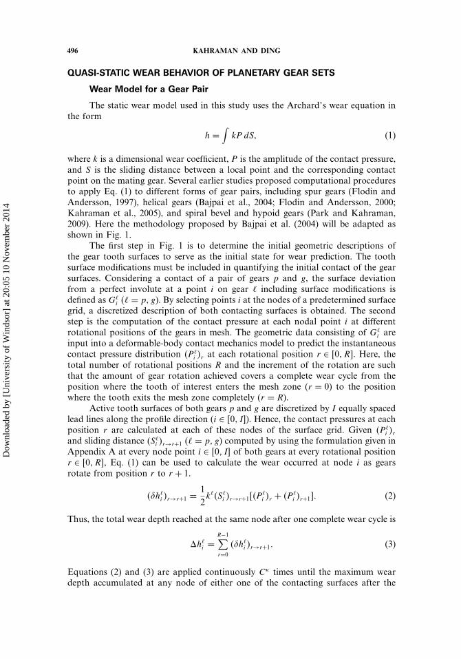
The static wear model used in this study uses the Archard’s wear equation inthe form
h =∫
kP dS� (1)
where k is a dimensional wear coefficient, P is the amplitude of the contact pressure,and S is the sliding distance between a local point and the corresponding contactpoint on the mating gear. Several earlier studies proposed computational proceduresto apply Eq. (1) to different forms of gear pairs, including spur gears (Flodin andAndersson, 1997), helical gears (Bajpai et al., 2004; Flodin and Andersson, 2000;Kahraman et al., 2005), and spiral bevel and hypoid gears (Park and Kahraman,2009). Here the methodology proposed by Bajpai et al. (2004) will be adapted asshown in Fig. 1.
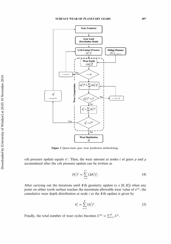
The first step in Fig. 1 is to determine the initial geometric descriptions ofthe gear tooth surfaces to serve as the initial state for wear prediction. The toothsurface modifications must be included in quantifying the initial contact of the gearsurfaces. Considering a contact of a pair of gears p and g, the surface deviationfrom a perfect involute at a point i on gear � including surface modifications isdefined as G�
i (� = p� g). By selecting points i at the nodes of a predetermined surfacegrid, a discretized description of both contacting surfaces is obtained. The secondstep is the computation of the contact pressure at each nodal point i at differentrotational positions of the gears in mesh. The geometric data consisting of G�
i areinput into a deformable-body contact mechanics model to predict the instantaneouscontact pressure distribution �P�
i �r at each rotational position r ∈ �0� R�. Here, thetotal number of rotational positions R and the increment of the rotation are suchthat the amount of gear rotation achieved covers a complete wear cycle from theposition where the tooth of interest enters the mesh zone (r = 0) to the positionwhere the tooth exits the mesh zone completely (r = R).
Active tooth surfaces of both gears p and g are discretized by I equally spacedlead lines along the profile direction (i ∈ �0� I�). Hence, the contact pressures at eachposition r are calculated at each of these nodes of the surface grid. Given �P�
i �rand sliding distance �S�
i �r→r+1 (� = p� g) computed by using the formulation given inAppendix A at every node point i ∈ �0� I� of both gears at every rotational positionr ∈ �0� R�, Eq. (1) can be used to calculate the wear occurred at node i as gearsrotate from position r to r + 1.
��h�i �r→r+1 =
12k��S�
i �r→r+1��P�i �r + �P�
i �r+1�� (2)
Thus, the total wear depth reached at the same node after one complete wear cycle is
h�i =
R−1∑r=0
��h�i �r→r+1� (3)
Equations (2) and (3) are applied continuously C times until the maximum weardepth accumulated at any node of either one of the contacting surfaces after the
Dow
nloa
ded
by [
Uni
vers
ity o
f W
inds
or]
at 2
0:05
10
Nov
embe
r 20
14
SURFACE WEAR OF PLANETARY GEARS 497
Figure 1 Quasi-static gear wear prediction methodology.
th pressure update equals �. Then, the wear amount at nodes i of gears p and g
accumulated after the th pressure update can be written as
�h�i �
=C∑c=1
�h�i �
c � (4)
After carrying out the iterations until Kth geometry update ( ∈ �0� K�) when anypoint on either tooth surface reaches the maximum allowable wear value of �tot, thecumulative wear depth distribution at node i at the Kth update is given by
h�i =
K∑=1
�h�i �
� (5)
Finally, the total number of wear cycles becomes Ctot = ∑K=1 C
.
Dow
nloa
ded
by [
Uni
vers
ity o
f W
inds
or]
at 2
0:05
10
Nov
embe
r 20
14
498 KAHRAMAN AND DING
Wear Model for a Planetary Gear Set
A quasi-static wear model above applies to both external and internal gearmeshes. Static load distribution analyses of external and internal meshes areperformed separately using a gear load distribution model (Load DistributionProgram, LDP, 2008) over one entire mesh cycle under the nominal mesh forcevalue. Such an analysis of a sun-planet n (s-pn) mesh and a ring-planet n (r-pn)mesh yields the corresponding contact pressures �P
s-pni �r and �P
r-pni �r for each
geometry update . The gear mesh torque values are calculated by assuming thateach planet branch carries an equal 1/N share of the input torque. This is, however,often not the case due to various manufacturing errors and assembly variationsassociated with the gears and the planet carrier (Bodas and Kahraman, 2004; Ligataet al., 2008; Singh et al., 2008). For such cases, Ligata’s closed-form planet load-sharing formulas (Ligata et al., 2009) can be used to calculate the gear mesh forcesof each planet. Meanwhile, the sliding distances of an s-pn mesh, �Ss/pn
i �r→r+1 (slidingdistance of the ith node of the sun gear tooth relative to the surface of planet n)and �S
pn/si �r→r+1 (sliding distance of the ith node of the planet gear tooth relative to
the surface of the sun gear) are found by using the procedure defined in AppendixA. Likewise, instantaneous sliding distances of an r-pn mesh are also determinedas �Sr/pn
i �r→r+1 and �Spn/ri �r→r+1. Next, wear analyses are performed for both meshes
and wear geometry updates are performed for all gear teeth until the maximum weardepth on any gear tooth profile reaches the predetermined wear threshold value.These wear iterations are continued until user-defined maximum number of cyclesor the maximum allowable wear depth value is reached.
DYNAMIC MODEL OF A PLANETARY GEAR SET
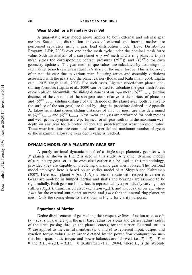
A purely torsional dynamic model of a single-stage planetary gear set withN planets as shown in Fig. 2 is used in this study. Any other dynamic modelsof a planetary gear set as the ones cited earlier can be used in this methodology,provided they are capable of predicting dynamic gear mesh forces. The torsionalmodel employed here is based on an earlier model of Al-Shyyab and Kahraman(2007). Here, each planet n �n ∈ �1� N�� is free to rotate with respect to carrier c.Gears are modeled as lumped inertias and shafts and bearings are assumed to berigid radially. Each gear mesh interface is represented by a periodically varying meshstiffness Kjpn�t�, transmission error excitation ejpn�t�, and viscous damper cjp, wherej = s for the external sun-planet pn mesh and j = r for the internal ring-planet pnmesh. Only the spring elements are shown in Fig. 2 for clarity purposes.
Equations of Motion
Define displacements of gears along their respective lines of action as uj = rj�j(j = c, r, s� pn), where rj is the gear base radius for a gear and carrier radius (radiusof the circle passing through the planet centers) for the carrier. External torquesTj are applied to the central members (s, r, and c) to represent input, output, andreaction torque values in an order dictated by the power flow configuration suchthat both quasi-static torque and power balances are achieved, i.e., Ts + Tr + Tc =0 and Ts s + Tr r + Tc c = 0 (Kahraman et al., 2004), where j is the absolute
Dow
nloa
ded
by [
Uni
vers
ity o
f W
inds
or]
at 2
0:05
10
Nov
embe
r 20
14
SURFACE WEAR OF PLANETARY GEARS 499
Figure 2 N + 3 degree-of-freedom torsional dynamic model of a planetary gear set.
velocity of the central member j. With the mass of a planet mp and mass momentsof inertia of each gear and the carrier Jj given, equations of motion of the (N + 3)degree-of-freedom torsional model are given as
[Jcr2c
+ Nmp
]uc + cbcuc + Kbcuc −
N∑n=1
�crpprpn�t�+csppspn�t�
+HrpnKrpn�t�prpn�t�+HspnKspn�t�pspn�t�� =Tc
rc� (6a)
Jrr2rur + cbr ur + Kbrur +
N∑i=1
�crpprpn�t�+HrpnKrpn�t�prpn�t�� =Tr
rr� (6b)
Jsr2sus + cbsus + Kbsus +
N∑i=1
�csppspn�t�+HspnKspn�t�pspn�t�� =Ts
rs� (6c)
Jp
r2pupn − crpprpn�t�+ csppspn�t�−HrpnKrpn�t�prpn�t�
+HspnKspn�t�pspn�t� = 0� n ∈ �1� N�� (6d)
Here, relative gear mesh displacements are defined as pjpn�t� = uj − uc − �jupn −ejpn�t� where �j = 1 for a ring-planet n mesh and �j = −1 for a sun-planet n mesh.The coefficients cbj and Kbj (j = c� r� s) are the torsional support damping andstiffness values, respectively.
As planetary gear sets are typically designed with larger gear backlash values,the back collisions of the teeth are not included in this analysis. The nonlinearity
Dow
nloa
ded
by [
Uni
vers
ity o
f W
inds
or]
at 2
0:05
10
Nov
embe
r 20
14
500 KAHRAMAN AND DING
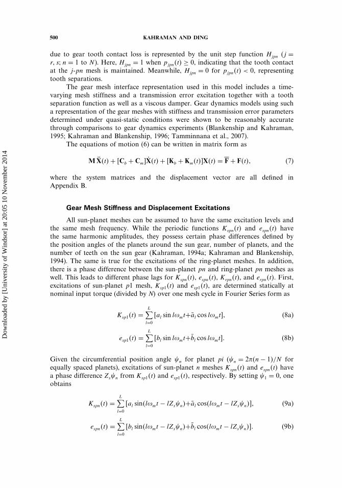
due to gear tooth contact loss is represented by the unit step function Hjpn (j =r� s� n = 1 to N ). Here, Hjpn = 1 when pjpn�t� ≥ 0, indicating that the tooth contactat the j-pn mesh is maintained. Meanwhile, Hjpn = 0 for pjpn�t� < 0, representingtooth separations.
The gear mesh interface representation used in this model includes a time-varying mesh stiffness and a transmission error excitation together with a toothseparation function as well as a viscous damper. Gear dynamics models using sucha representation of the gear meshes with stiffness and transmission error parametersdetermined under quasi-static conditions were shown to be reasonably accuratethrough comparisons to gear dynamics experiments (Blankenship and Kahraman,1995; Kahraman and Blankenship, 1996; Tamminnana et al., 2007).
The equations of motion (6) can be written in matrix form as
MX�t�+ �Cb + Cm�X�t�+ �Kb + Km�t��X�t� =�F+ F�t�� (7)
where the system matrices and the displacement vector are all defined inAppendix B.
Gear Mesh Stiffness and Displacement Excitations
All sun-planet meshes can be assumed to have the same excitation levels andthe same mesh frequency. While the periodic functions Kspn�t� and espn�t� havethe same harmonic amplitudes, they possess certain phase differences defined bythe position angles of the planets around the sun gear, number of planets, and thenumber of teeth on the sun gear (Kahraman, 1994a; Kahraman and Blankenship,1994). The same is true for the excitations of the ring-planet meshes. In addition,there is a phase difference between the sun-planet pn and ring-planet pn meshes aswell. This leads to different phase lags for Kspn�t�, espn�t�, Krpn�t�, and erpn�t�. First,excitations of sun-planet p1 mesh, Ksp1�t� and esp1�t�, are determined statically atnominal input torque (divided by N� over one mesh cycle in Fourier Series form as
Ksp1�t� =L∑l=0
�al sin l�mt+al cos l�mt�� (8a)
esp1�t� =L∑l=0
�bl sin l�mt+bl cos l�mt�� (8b)
Given the circumferential position angle �n for planet pi (�n = 2��n− 1�/N forequally spaced planets), excitations of sun-planet n meshes Kspn�t� and espn�t� havea phase difference Zs�n from Ksp1�t� and esp1�t�, respectively. By setting �1 = 0, oneobtains
Kspn�t� =L∑l=0
�al sin�l�mt − lZs�n�+al cos�l�mt − lZs�n��� (9a)
espn�t� =L∑l=0
�bl sin�l�mt − lZs�n�+bl cos�l�mt − lZs�n��� (9b)
Dow
nloa
ded
by [
Uni
vers
ity o
f W
inds
or]
at 2
0:05
10
Nov
embe
r 20
14
SURFACE WEAR OF PLANETARY GEARS 501
Here, �m is the gear mesh frequency determined from the kinematic relationships asa function of rotational speeds of the sun or ring gears s and r as
�m =
Zs s� fixed carrier
ZsZr
Zs + Zr
s� fixed ring
ZsZr
Zs + Zr
r fixed sun.
(9c)
Meanwhile, Krp1�t� and erp1�t� have a phase angle of �rs with Ksp1�t� andesp1�t�, respectively. This phase angle is determined primarily by the number ofplanet teeth (Kahraman, 1994a; Kahraman and Blankenship, 1994). The internalgear geometry is used to determine the mesh stiffness and the transmission errorover one mesh cycle under the nominal mesh force that can be written in relationto Ksp1�t� and esp1�t� as
Krpn�t� =L∑l=0
�cl sin�l�mt − l�rs + lZr�n�+ cl cos�l�mt − l�rs + lZr�n��� (10a)
erpn�t� =L∑l=0
�dl sin�l�mt − l�rs + lZr�n�+ dl cos�l�mt − l�rs + lZr�n��� (10b)
where Zr�n is the phase angle between the first ring-planet mesh and any ring-planet n mesh. In this study, harmonic amplitudes of Kspn�t�, espn�t�, Krpn�t�, erpn�t�required by Eqs. (8)–(10) were determined by using a gear load distribution model(Load Distribution Program, LDP, 2008). This model is based on earlier study byConry and Seireg (1973). Several similar semi-analytical FE-based models have beencommonly used in power transmission industry to predict the gear load distributionand resultant parameters including tooth forces, transmission error, and gear meshstiffness. Any of those models can be used here for the purpose of defining harmonicamplitudes of Kspn�t�, espn�t�, Krpn�t�, and erpn�t�.
DYNAMIC WEAR METHODOLOGY FOR PLANETARY GEAR SETS
As the first step in the process, quasi-static load distribution analyses ofreference sun-planet and ring-planet meshes are performed under nominal torquesTs/N and ZpTs/�ZsN�, respectively, to obtain Ksp1�t�, Krp1�t�, esp1�t�, and erp1�t�at each geometry update . Then, Eqs. (9) and (10) are used to obtain the meshstiffness and displacement excitations for all other gear meshes. Next, the torsionaldynamic model is employed to predict forced response of the planetary gear set atany desired gear mesh frequency �m (corresponding to a certain rotational speed).
Assuming that the damping components are negligibly small, the dynamicexternal and internal gear mesh forces at a time instant t are obtained as Fs-pn
m �t� =HspnKspn�t�pspn�t� and Fr-pn
m �t� = HrpnKrpn�t�prpn�t�. Then, separate load distributionanalyses are performed for both s-pn mesh with a mesh force Fs-pn
m �t� and r-pn meshwith a mesh force Fr-pn
m �t� to obtain the dynamic tooth forces Fs-pnt �t� and F
r-pnt �t�.
These dynamic tooth forces are then used according to the procedure provided
Dow
nloa
ded
by [
Uni
vers
ity o
f W
inds
or]
at 2
0:05
10
Nov
embe
r 20
14
502 KAHRAMAN AND DING
in the section “Quasi-Static Wear Behavior of Planetary Gear Sets” to computeinstantaneous contact pressures �Ps-pn
i �=0r and �P
r-pni �=0
r for the initial tooth profileswithout wear. Next, wear analyses are performed to compute wear depths for bothmeshes with these contact pressures and the corresponding sliding distances definedin Appendix A.
Once wear amount at any point on any gear mesh reaches a threshold value towarrant a geometry update, load distribution analyses are repeated with worn gearprofiles to obtain Kjpn�t� and ejpi�t� for the meshes with the current distributions ofwear. The dynamic model and LDP then yield new F
s-pnt �t� and F
r-pnt �t� that are used
for determining updated instantaneous pressures �Ps-pni �r and �P
r-pni �r . These new
pressure values and the sliding distances are used to find the wear depths after theth geometry update. These iterations are repeated until the maximum wear depthon any gear tooth profile reaches the user-defined threshold value.
The same approximate method is used by Ding and Kahraman (2007) toaccount for the influence of lubrication conditions at the gear mesh contact on thewear coefficient k. Here, the wear coefficient k is defined as
k =
k0� � <12�
27k0�4− ���
12< � < 4�
0� � > 4�
(11)
Here, � is the so-called lambda ratio defined as the ratio of the minimum filmthickness hmin to the composite surface roughness Rq = �R2
qp + R2qg�
1/2, where Rqp andRqg are the root-mean-square (rms) surface roughness values of gears p and g ata contact point in the direction of the involute profile. Equation (11) assumes thatthe wear coefficient is equal to k0 for � < 1
2 that corresponds to the values observedat relatively low speeds such as the ones measured by Bajpai et al. (2004). It alsoassumes that k = 0 for � > 4, i.e., no wear will occur if hmin is at least four timesmore than Rq. In the transition region within 1
2 < � < 4, k reduces linearly from k0to zero. Here, the value of hmin is defined using the formula by Dowson (1998) fortwo smooth surfaces in contact.
EXAMPLE PLANETARY GEAR DYNAMIC WEAR SIMULATIONS
An example spur planetary gear set with four equally spaced planets (N =4) is considered here to demonstrate the dynamic wear characteristics of aplanetary gear set. An equally spaced four-planet gear set represents the mostcommon configuration used in automatic transmissions for automotive and truckapplications. Design parameters of the example gear set related to the dynamic wearanalysis are listed in Table 1 as well as the estimated system parameters requiredfor the dynamic analysis. Damping values are adjusted to correspond to about 3%modal damping. The carrier is held stationary in these simulations by assigning avery large value to Kbc. This effectively reduces the degrees of freedom by N + 2 =6. The input and output members are chosen as the sun gear and the ring gear,respectively. A constant torque of Ts = 600Nm is applied to the sun gear.
Dow
nloa
ded
by [
Uni
vers
ity o
f W
inds
or]
at 2
0:05
10
Nov
embe
r 20
14
SURFACE WEAR OF PLANETARY GEARS 503
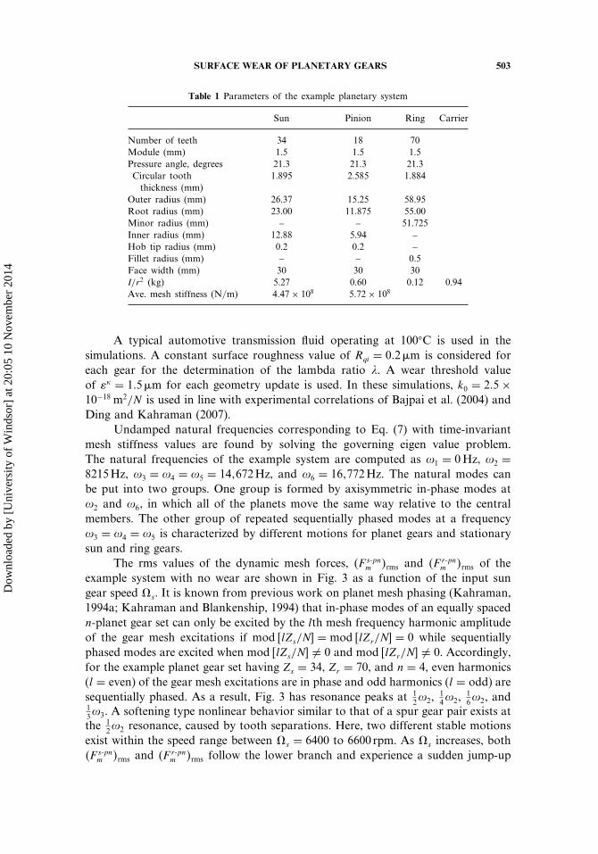
Table 1 Parameters of the example planetary system
Sun Pinion Ring Carrier
Number of teeth 34 18 70Module (mm) 1.5 1.5 1.5Pressure angle, degrees 21.3 21.3 21.3Circular tooththickness (mm)
1.895 2.585 1.884
Outer radius (mm) 26.37 15.25 58.95Root radius (mm) 23.00 11.875 55.00Minor radius (mm) – – 51.725Inner radius (mm) 12.88 5.94 –Hob tip radius (mm) 0.2 0.2 –Fillet radius (mm) – – 0.5Face width (mm) 30 30 30I/r2 (kg) 5.27 0.60 0.12 0.94Ave. mesh stiffness (N/m) 4�47× 108 5�72× 108
A typical automotive transmission fluid operating at 100�C is used in thesimulations. A constant surface roughness value of Rqi = 0�2�m is considered foreach gear for the determination of the lambda ratio �. A wear threshold valueof � = 1�5�m for each geometry update is used. In these simulations, k0 = 2�5×10⁻¹⁸ m2/N is used in line with experimental correlations of Bajpai et al. (2004) andDing and Kahraman (2007).
Undamped natural frequencies corresponding to Eq. (7) with time-invariantmesh stiffness values are found by solving the governing eigen value problem.The natural frequencies of the example system are computed as �1 = 0Hz, �2 =8215Hz, �3 = �4 = �5 = 14�672Hz, and �6 = 16�772Hz. The natural modes canbe put into two groups. One group is formed by axisymmetric in-phase modes at�2 and �6, in which all of the planets move the same way relative to the centralmembers. The other group of repeated sequentially phased modes at a frequency�3 = �4 = �5 is characterized by different motions for planet gears and stationarysun and ring gears.
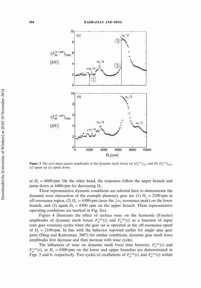
The rms values of the dynamic mesh forces, �F s-pnm �rms and �F r-pn
m �rms of theexample system with no wear are shown in Fig. 3 as a function of the input sungear speed s. It is known from previous work on planet mesh phasing (Kahraman,1994a; Kahraman and Blankenship, 1994) that in-phase modes of an equally spacedn-planet gear set can only be excited by the lth mesh frequency harmonic amplitudeof the gear mesh excitations if mod �lZs/N� = mod �lZr/N� = 0 while sequentiallyphased modes are excited when mod �lZs/N� �= 0 and mod �lZr/N� �= 0. Accordingly,for the example planet gear set having Zs = 34, Zr = 70, and n = 4, even harmonics(l = even) of the gear mesh excitations are in phase and odd harmonics (l = odd) aresequentially phased. As a result, Fig. 3 has resonance peaks at 1
2�2,14�2,
16�2, and
13�3. A softening type nonlinear behavior similar to that of a spur gear pair exists atthe 1
2�2 resonance, caused by tooth separations. Here, two different stable motionsexist within the speed range between s = 6400 to 6600 rpm. As s increases, both�F s-pn
m �rms and �F r-pnm �rms follow the lower branch and experience a sudden jump-up
Dow
nloa
ded
by [
Uni
vers
ity o
f W
inds
or]
at 2
0:05
10
Nov
embe
r 20
14
504 KAHRAMAN AND DING
Figure 3 The root-mean-square amplitudes of the dynamic mesh forces (a) �F s-pnm �rms and (b) �F r-pn
m �rms;(o) speed up (x) speed down.
at s = 6600 rpm. On the other hand, the responses follow the upper branch andjump down at 6400 rpm for decreasing s.
Three representative dynamic conditions are selected here to demonstrate thedynamic wear interaction of the example planetary gear set: (1) s = 2100 rpm inoff-resonance region, (2) s = 6500 rpm (near the 1
2�2 resonance peak) on the lowerbranch, and (3) again s = 6500 rpm on the upper branch. These representativeoperating conditions are marked in Fig. 3(a).
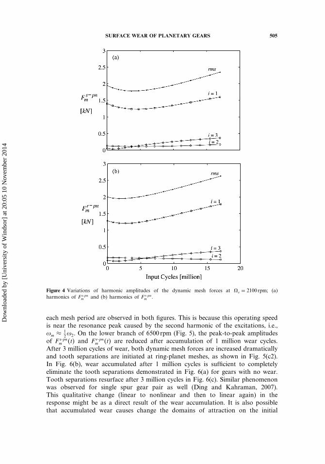
Figure 4 illustrates the effect of surface wear on the harmonic (Fourier)amplitudes of dynamic mesh forces Fs-pn
m �t� and Fr-pnm �t� as a function of input
(sun gear rotation) cycles when the gear set is operated at the off-resonance speedof s = 2100 rpm. In line with the behavior reported earlier for single spur gearpairs (Ding and Kahraman, 2007) for similar conditions, dynamic gear mesh forceamplitudes first decrease and then increase with wear cycles.
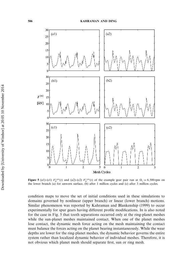
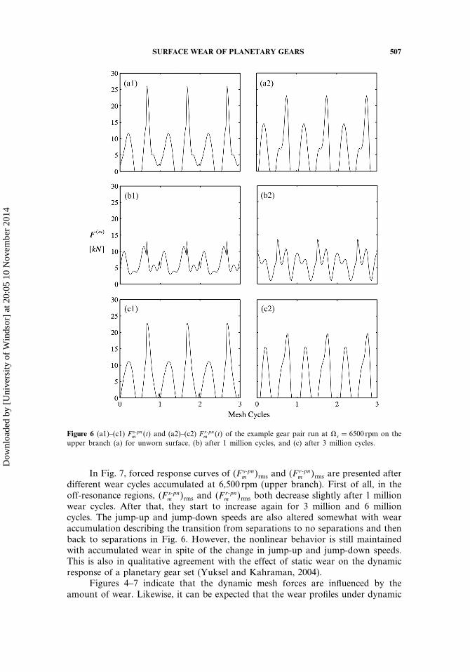
The influences of wear on dynamic mesh force time histories, Fs-pnm �t� and
Fr-pnm �t�, at s = 6500 rpm on the lower and upper branches are demonstrated in
Figs. 5 and 6, respectively. Two cycles of oscillations of Fs-pnm �t� and Fr-pn
m �t� within
Dow
nloa
ded
by [
Uni
vers
ity o
f W
inds
or]
at 2
0:05
10
Nov
embe
r 20
14
SURFACE WEAR OF PLANETARY GEARS 505
Figure 4 Variations of harmonic amplitudes of the dynamic mesh forces at s = 2100 rpm; (a)harmonics of Fs-pn
m and (b) harmonics of Fr-pnm .
each mesh period are observed in both figures. This is because this operating speedis near the resonance peak caused by the second harmonic of the excitations, i.e.,�m ≈ 1
2�2. On the lower branch of 6500 rpm (Fig. 5), the peak-to-peak amplitudesof Fs-pn
m �t� and Fr-pnm �t� are reduced after accumulation of 1 million wear cycles.
After 3 million cycles of wear, both dynamic mesh forces are increased dramaticallyand tooth separations are initiated at ring-planet meshes, as shown in Fig. 5(c2).In Fig. 6(b), wear accumulated after 1 million cycles is sufficient to completelyeliminate the tooth separations demonstrated in Fig. 6(a) for gears with no wear.Tooth separations resurface after 3 million cycles in Fig. 6(c). Similar phenomenonwas observed for single spur gear pair as well (Ding and Kahraman, 2007).This qualitative change (linear to nonlinear and then to linear again) in theresponse might be as a direct result of the wear accumulation. It is also possiblethat accumulated wear causes change the domains of attraction on the initial
Dow
nloa
ded
by [
Uni
vers
ity o
f W
inds
or]
at 2
0:05
10
Nov
embe
r 20
14
506 KAHRAMAN AND DING
Figure 5 (a1)–(c1) Fs-pnm �t� and (a2)–(c2) Fr-pn
m �t� of the example gear pair run at s = 6�500 rpm onthe lower branch (a) for unworn surface, (b) after 1 million cycles and (c) after 3 million cycles.
condition maps to move the set of initial conditions used in these simulations todomains governed by nonlinear (upper branch) or linear (lower branch) motions.Similar phenomenon was reported by Kahraman and Blankenship (1999) to occurexperimentally for spur gears having different profile modifications. In is also notedfor the case in Fig. 5 that tooth separations occurred only at the ring-planet mesheswhile the sun-planet meshes maintained contact. When one of the planet mesheslose contact, the dynamic mesh force acting on the mesh maintaining the contactmust balance the forces acting on the planet bearing instantaneously. While the weardepths are lower for the ring-planet meshes, the dynamic behavior governs the entiresystem rather than localized dynamic behavior of individual meshes. Therefore, it isnot obvious which planet mesh should separate first, sun or ring mesh.
Dow
nloa
ded
by [
Uni
vers
ity o
f W
inds
or]
at 2
0:05
10
Nov
embe
r 20
14
SURFACE WEAR OF PLANETARY GEARS 507
Figure 6 (a1)–(c1) Fs-pnm �t� and (a2)–(c2) Fr-pn
m �t� of the example gear pair run at s = 6500 rpm on theupper branch (a) for unworn surface, (b) after 1 million cycles, and (c) after 3 million cycles.
In Fig. 7, forced response curves of �F s-pnm �rms and �F r-pn
m �rms are presented afterdifferent wear cycles accumulated at 6,500 rpm (upper branch). First of all, in theoff-resonance regions, �F s-pn
m �rms and �F r-pnm �rms both decrease slightly after 1 million
wear cycles. After that, they start to increase again for 3 million and 6 millioncycles. The jump-up and jump-down speeds are also altered somewhat with wearaccumulation describing the transition from separations to no separations and thenback to separations in Fig. 6. However, the nonlinear behavior is still maintainedwith accumulated wear in spite of the change in jump-up and jump-down speeds.This is also in qualitative agreement with the effect of static wear on the dynamicresponse of a planetary gear set (Yuksel and Kahraman, 2004).
Figures 4–7 indicate that the dynamic mesh forces are influenced by theamount of wear. Likewise, it can be expected that the wear profiles under dynamic
Dow
nloa
ded
by [
Uni
vers
ity o
f W
inds
or]
at 2
0:05
10
Nov
embe
r 20
14

508 KAHRAMAN AND DING
Figure 7 (a) �F s-pnm �rms and (b) �F r-pn
m �rms after operation at s = 6500 rpm on the upper branch aftervarious wear cycles.
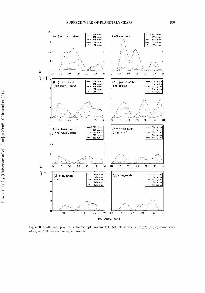
conditions should be different from those accumulated under low-speed quasi-staticconditions. Figure 8 compares quasi-static wear profiles to those accumulated at s = 6500 rpm on the upper branch. It is observed that the predicted dynamic wearprofiles are clearly different from their quasi-static counterparts in both amplitudeand shape. Nearly two fluctuations per mesh cycle are shown in the dynamic wearprofiles as a direct result of the mesh force fluctuation shown in Figs. 5 and 6.In addition, the wear profiles also exhibit signs of tooth separations for both s-pmesh and r-p meshes. For instance, in Fig. 8(a2) the initial dynamic wear profilesshow zero wear within sun gear roll angle ranges of 20�5�–22�3� until 1 millionsun gear wear cycles due to tooth separation. It is also evident from Fig. 8 thattooth separations are introduced again after 6 million cycles, resulting in relativelyunchanged wear depths within 17�–18� roll angle. Both dedendum and addendumwear amplitudes at 6500 rpm are higher for each mesh than those under staticconditions. The overall maximum wear depth at 6500 rpm, located near the start ofactive profile (SAP) of the sun gear, is about 16�5�m after 8 million wear cycles, incomparison to 12�m under the quasi-static condition. In spite of the reduced wear
Dow
nloa
ded
by [
Uni
vers
ity o
f W
inds
or]
at 2
0:05
10
Nov
embe
r 20
14
SURFACE WEAR OF PLANETARY GEARS 509
Figure 8 Tooth wear profiles in the example system; (a1)–(d1) static wear and (a2)–(d2) dynamic wearat s = 6500 rpm on the upper branch.
Dow
nloa
ded
by [
Uni
vers
ity o
f W
inds
or]
at 2
0:05
10
Nov
embe
r 20
14
510 KAHRAMAN AND DING
coefficient at 6500 rpm due to the increased lambda ratio, significant increases inmesh force amplitudes near SAP cause these higher wear amplitudes.
Focusing on the wear depth profiles presented in Fig. 8, one would expectthe relative wear depths at each mesh to be proportional to the correspondingwear cycles experienced by each mesh. With a fixed carrier, a given sun gear toothin the example gear set shows four wear cycles per input (sun) rotation while atooth on the planet meshing with the sun gear experiences 34/18 = 1�89 wear cyclessuch that the ratio of the wear cycles of the sun and planet teeth is 4/1�89 =2�11. However, the ratio of the maximum wear depth on a sun gear tooth to themaximum wear depth on a planet tooth is higher than this. The same behavior wasdemonstrated in earlier studies for single gear pairs where the wear depth ratio didnot equal the cycle ratio. One reason for this is that the sliding distance �S
pi �r→r+1
experience by gear p, calculated through Eq. (A4) of Appendix A is different thanthe sliding distance �S
gi �r→r+1 experienced by gear g (Bajpai et al., 2004; Flodin and
Andersson, 1997, 2000).
CONCLUSIONS
In this paper, the dynamics-wear interactions are studied for planetary gearsets formed by spur gears. Based on the results presented in this study, the followingconclusions can be made:
• While the wear depths at the ring-planet meshes are generally smaller thanthose at the sun-planet meshes due to the reduced wear cycles, they are stillquite significant, influencing the dynamic response. Therefore, a planetary gearwear analysis must consider both sun and ring gear meshes, in contrast to theassumption of negligible internal gear pair wear made in previous work (Yukseland Kahraman, 2004).
• As in single gear pairs, surface wear impacts the fundamental harmonic amplitudethe most in off-resonance regions. In addition, it has the effect to first decreaseand then increase the dynamic forces in both off-resonance and resonance regions.
• Surface wear influences the forced responses in terms of vibration amplitudesand harmonic components both quantitatively and qualitatively. A spur planetarygear set is inherently nonlinear and exhibits softening-type nonlinear behavior atsome of its resonance peaks, characterized by sudden jumps of force amplitudes.Surface wear not only affects the vibration amplitudes but also the nature of thenonlinear response.
• Dynamic gear mesh forces impact the wear profiles at all meshes of a planetarygear set significantly. Higher wear depths and unique wear shapes are predictedespecially in the resonance regions due to the increased dynamic mesh loads.
APPENDIX A
Surface Wear Sliding Distance Formulation
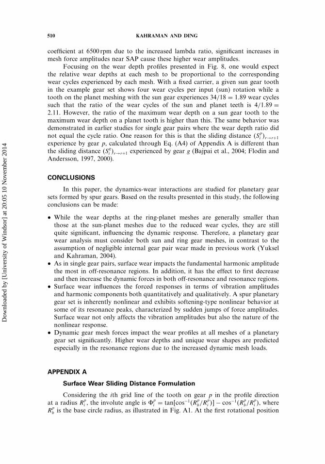
Considering the ith grid line of the tooth on gear p in the profile directionat a radius Rp
i , the involute angle is �pi = tan�cos−1�R
pb/R
pi ��− cos−1�R
pb/R
pi �, where
Rpb is the base circle radius, as illustrated in Fig. A1. At the first rotational position
Dow
nloa
ded
by [
Uni
vers
ity o
f W
inds
or]
at 2
0:05
10
Nov
embe
r 20
14
SURFACE WEAR OF PLANETARY GEARS 511
Figure A1 Involute angle of gear p and the coordinate frame.
r = 0 when the contact is at the start of the active profile of the driving gear p, theposition vector of a nodal point of contact at radius Rp
i is defined as
�Xpi �r=0 = R�
Rpi sin�
pi
Rpi cos�
pi
0
� (A1)
where the vector on the right-hand side represents the involute profile at a positionwhere the intersection point of involute profile and the base circle is on the line ofgear centers. The rotation transformation matrix R� rotates the involute profile fromthis reference position by an angle of � to establish the position �Xp
i �r=0 at the SAP.At the same radius, the position vector of the same point i is given at any positionr as
�Xpi �r = Rr�p�X
pi �r=0� (A2)
Dow
nloa
ded
by [
Uni
vers
ity o
f W
inds
or]
at 2
0:05
10
Nov
embe
r 20
14
512 KAHRAMAN AND DING
Here, r�p is the angular position of gear p measured from r = 0, �p is therotational increment of gear p and R is the corresponding rotation transformationmatrix.
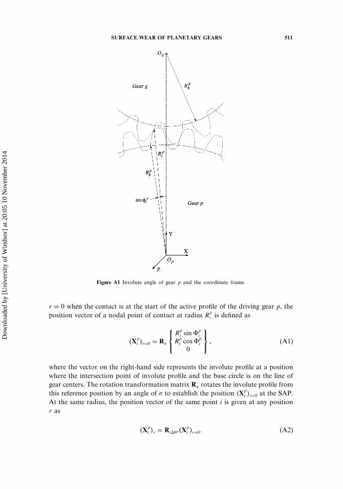
The sliding distance �Spi �r→r+1 is defined as the distance by which a point
represented by node i on gear p slides with respect to its corresponding point onits mating gear as they rotate from position r to position r + 1. As illustrated inFig. A2(a), when the leading edge of the contact zone reaches a node i of gear p atr = m, node i meshes with node q of gear g and experiences a nonzero pressure forthe first time since the beginning of loading cycle. Position vector �Xp
i �r=m of node i
at r = m is given by Eq. (A2) and since points i and q overlap in space, �Xgq�r=m =
�Xpi �r=m. When the gears are rotated by one incremental rotation to position to r =
m+ 1 as shown in Fig. A2(b), �Xpi �r=m+1 is again defined by Eq. (A2). Meanwhile,
node q on gear g no longer overlaps with node i on gear p as gear g rotates aboutits own center. The position vector of node q is obtained by first translating thecoordinate frame from the center of gear p to the center of gear g, then rotating itby �g, and finally translating it back to the center of gear p�
�Xgq�r=m+1 = R�g ��X
gq�r=m + TE�− TE� (A3)
Here, �g = −�Zp/Zg� �p and Zp and Zg are the number of teeth of gears p andg, respectively, E is the center distance, and T is the translation vector. If node i
remains within contact zone until position r = t� the sliding distance that occurs
Figure A2 Sliding distance of point i on gear p at different rotational positions r.
Dow
nloa
ded
by [
Uni
vers
ity o
f W
inds
or]
at 2
0:05
10
Nov
embe
r 20
14
SURFACE WEAR OF PLANETARY GEARS 513
when gears rotate from any position r to r + 1 can be written in general terms as
�Spi �r→r+1 =
∣∣∣∣∥∥�Xg
q�r+1 − �Xpi �r+1
∥∥−r∑
u=m
�Spi ��u−1�→u
∣∣∣∣ � m ≤ r ≤ t�
0� else�(A4)
The sliding distance of the corresponding node q on gear g, �Sgq�r→r+1, is also
determined by using the same procedure.
APPENDIX B
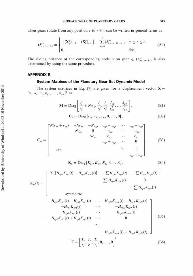
System Matrices of the Planetary Gear Set Dynamic Model
The system matrices in Eq. (7) are given for a displacement vector X =�uc� ur� us� up1� � � � � upN �
T as
M = Diag
[Jcr2c
+ Nmp�Jrr2r�Jsr2s�Jp1
r2p1� � � �
JpN
r2pN
]� (B1)
Cb = Diag �cbc� cbr� cbs� 0� � � � � 0� � (B2)
Cm =
N�crp + csp� −Ncrp −Ncsp crp − csp · · · crp − cspNcrp 0 −crp · · · −crp
Ncsp csp · · · cspcrp + csp · · · 0
sym� � �
���
crp + csp
� (B3)
Kb = Diag �Kbc� Kbr� Kbs� 0� � � � 0� � (B4)
Km�t� =
∑�HrpnKrpi�t�+HspnKspn�t�� −∑
HrpnKrpn�t� −∑HspnKspn�t�∑
HrpnKrpn�t� 0∑HspnKspn�t�
symmetric
∣∣∣∣∣∣∣∣∣∣∣
·
∣∣∣∣∣∣∣∣∣∣∣∣∣∣∣
Hrp1Krp1�t�−Hsp1Ksp1�t� · · · HrpNKrpN �t�−HspNKspN �t�
−Hrp1Krp1�t� · · · −HrpNKrpN �t�
Hsp1Ksp1�t� · · · HspNKspN �t�
Hrp1Krp1�t�+Hsp1Ksp1�t� · · · 0
� � ����
HrpNKrpN �t�+HspNKspN �t�
(B5)
�F =[Tc
rc�Tr
rr�Ts
rs� 0� � � � � 0
]T
� (B6)
Dow
nloa
ded
by [
Uni
vers
ity o
f W
inds
or]
at 2
0:05
10
Nov
embe
r 20
14
514 KAHRAMAN AND DING
F�t� =
−∑�crperpn�t�+ cspespn�t�+HrpnKrpn�t�erpn�t�+HspnKspn�t�espn�t��∑
�crperpn�t�+HrpnKrpn�t�erpn�t��∑�cspespn�t�+HspiKspn�t�espn�t��
−crperp1�t�+ cspesp1�t�−Hrp1Krp1�t�erp1�t�+Hsp1Ksp1�t�esp1�t����
−crperpN �t�+ cspespN �t�−HrpNKrpN �t�erpN �t�+HspNKspN �t�espN �t�
�
(B7)
REFERENCES
Al-Shyyab, A., Kahraman, A. (2007). Non-linear dynamic model for planetary gearsets. Proc. IMechE, Part K: Journal of Multi-Body Dynamics 221:567–576.
Bajpai, P., Kahraman, A., Anderson, N. E. (2004). A surface wear predictionmethodology for parallel axis gear pairs. Journal of Tribology 126:597–604.
Blankenship, G. W., Kahraman, A. (1995). Steady state forced response of amechanical oscillator with combined parametric excitation and clearance typenonlinearity. Journal of Sound and Vibration 185:743–776.
Bodas, A., Kahraman, A. (2004). Influence of carrier and gear manufacturing errorson the static load sharing behavior of planetary gear sets. JSME InternationalJournal, Series C 47:908–915.
Botman, M. (1976). Epicyclic gear vibrations. ASME Journal of Engineering forIndustry 97:811–815.
Conry, T. F., Seireg, A. (1973). A mathematical programming technique for theevaluation of load distribution and optimal modifications for gear systems. ASMEJournal of Engineering for Industry, Series B 95:1115–1122.
Cunliffe, F., Smith, J. D., Welbourn, D. B. (1974). Dynamic tooth loads in epicyclicgear. ASME Journal of Engineering for Industry 95:578–584.
Ding, H., Kahraman, A. (2007). Interactions between nonlinear spur gear dynamicsand surface wear. Journal of Sound and Vibration 307:662–679.
Dowson, D. (1998). Modelling of elasto-hydrodynamic lubrication of real solids byreal lubricants. Meccanica 33:47–58.
Flodin, A., Andersson, S. (1997). Simulation of mild wear in spur gears. Wear207:16–23.
Flodin, A., Andersson, S. (2000). Simulation of mild wear in helical gears. Wear241:123–128.
Kahraman, A. (1994a). Planetary gear train dynamics. Journal of Mechanical Design116:713–720.
Kahraman, A. (1994b). Natural modes of planetary gear trains. Journal of Soundand Vibration 173:125–130.
Kahraman, A. (1994c). Load sharing characteristics of planetary transmissions.Mechanisms and Machine Theory 29:1151–1165.
Kahraman, A., Blankenship, G. W. (1994). Planet mesh phasing in epicyclic gearsets. International Gearing Conference, Newcastle upon Tyne, UK, pp. 99–104.
Kahraman, A., Blankenship, G. W. (1996). Interaction between external andparametric excitations in systems with clearance. Journal of Sound and Vibration194:317–336.
Dow
nloa
ded
by [
Uni
vers
ity o
f W
inds
or]
at 2
0:05
10
Nov
embe
r 20
14
SURFACE WEAR OF PLANETARY GEARS 515
Kahraman, A., Blankenship, G. W. (1997). Experiments on nonlinear dynamicbehavior of an oscillator with clearance and periodically time-varying parameters.Journal of Applied Mechanics 64:217–226.
Kahraman, A., Blankenship, G. W. (1999). Effect of involute tip relief on dynamicresponse of spur gear pairs. Journal of Mechanical Design 121:313–315.
Kahraman, A., Bajpai, P., Anderson, N. (2005). Influence of tooth profile deviationson helical gear wear. Journal of Mechanical Design 127:656–663.
Kahraman, A., Kharazi, A. A., Umrani, M. (2003). A deformable body dynamicanalysis of planetary gears with thin rims. Journal of Sound and Vibration262:752–768.
Kahraman, A., Ligata, H., Kienzle, K., Zini, D. (2004). A kinematics and powerflow analysis methodology for automatic transmission planetary gear trains.Journal of Mechanical Design 126:1071–1081.
Ligata, H., Kahraman, A., Singh, A. (2008). An experimental study of the influenceof manufacturing errors on the planetary gear stresses and planet load sharing.Journal of Mechanical Design 130:041701-1–041701-9.
Ligata, H., Kahraman, A., Singh, A. (2009). Closed-form planet load sharingformulae for planetary gear sets using translational analogy. Journal of MechanicalDesign 131:021007-1–021007-7.
Lin, J., Parker, R. G. (2000). Structural vibration properties of planetary gears withunequally spaced planets. Journal of Sound and Vibration 233:921–928.
Load Distribution Program, LDP. (2008). The Ohio State University, Columbus,OH.
Park, D., Kahraman, A. (2009). A surface wear model for hypoid gear pairs. Wear267:1595–1604.
Saada, A., Velex, P. (1995). An extended model for the analysis of the dynamicbehavior of planetary trains. Journal of Mechanical Design 117:241–247.
Singh, A., Kahraman, A., Ligata, H. (2008). Internal gear strains and load sharingin planetary transmissions: model and experiments. Journal of Mechanical Design130:072602-1–072602-10.
Sun, T., Hu, H. (2003). Nonlinear dynamics of a planetary gear system with multipleclearances. Mechanisms and Machine Theory 38:1371–1390.
Tamminnana, V. K., Kahraman, A., Vijayakar, S. (2007). On the relationshipbetween the dynamic factors and dynamic transmission error of spur gear pairs.ASME Journal of Mechanical Design 129:75–84.
Yuksel, C., Kahraman, A. (2004). Dynamic tooth loads of planetary gear sets havingtooth profile wear. Mechanisms and Machine Theory 39:695–715.
Dow
nloa
ded
by [
Uni
vers
ity o
f W
inds
or]
at 2
0:05
10
Nov
embe
r 20
14