Embed Size (px)
Citation preview

1
A Membrane Process to Capture CO2from Coal-Fired Power Plant Flue Gas
Projects NT43085 and NT05312
T. Merkel, H. Lin, X. Wei, J. He, B. Firat, K. Amo, R. Daniels, R. BakerMembrane Technology and Research, Inc.
NETL review meetingMarch 26, 2009
www.mtrinc.com

2
• Project timeline and objectives overview
• Introduction to MTR
• Membrane technology background
• Results to date (project NT43085)
• New project (NT05312) objectives and future plans
Outline

3
Project number NT43085Project period: 4/1/07 to 3/31/09 Funding: $788,266 DOE; $197,066 MTR
DOE program manager: Heino Beckert, Participants: MTR, DOEBruce Lani
Project scope: investigate the feasibility of new polymer membranes and process for cost-effective capture of CO2 from power plant flue gas.
All project objectives were met within time and budget; details to follow.
Project number NT05312Project period: 10/1/08 to 9/30/10 Funding: $3,439,200 DOE; $957,630 cost share
DOE program manager: Jose Figueroa Participants: MTR, APS, EPRI, DOE
Project scope: field demonstrate the MTR membrane process with commercial-sized components at APS’s Cholla coal-fired power plant; at the conclusion of the project, be in a position to gauge the technical and economic viability of membrane-based CO2 capture from flue gas.
Project overview

4
Natural Gas:
Petrochemicals:
Hydrogen (Refinery):
Propylene/Nitrogen
CO2/CH4, CH4/N2NGL/CH4
H2/CH4, CO, CO2
Introduction to MTR
MTR designs, manufactures, and sells membrane systems for industrial gas separations
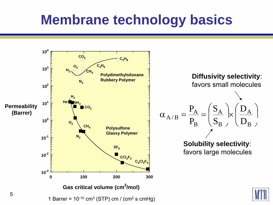
5
10-3
10-2
10-1
100
101
102
103
104
0 100 200 300
Permeability (Barrer)
PolydimethylsiloxaneRubbery Polymer
PolysulfoneGlassy Polymer
H2
O2
N2
CO2
CH4
C2H6
C3H8
C2Cl2F4
CCl2F2
SF6
CH4
N2
O2
CO2
NH3
H2He
Gas critical volume (cm3/mol)
Membrane technology basics
⎟⎠
⎞⎜⎝
⎛×⎟
⎠
⎞⎜⎝
⎛==α
B
A
B
A
B
AB/A D
DSS
PP
Solubility selectivity: favors large molecules
Diffusivity selectivity: favors small molecules
1 Barrer = 10-10 cm3 (STP) cm / (cm2 s cmHg)

6
• Spiral-wound and hollow fiber modules are used.
• Membranes have to be thin to provide useful fluxes.
Membrane technology basics
7
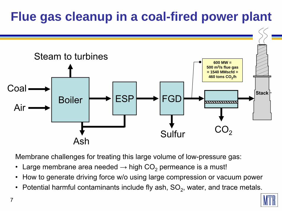
Flue gas cleanup in a coal-fired power plant
BoilerCoal
CO2
AirESP FGD
Ash
Steam to turbines
Membrane challenges for treating this large volume of low-pressure gas:• Large membrane area needed → high CO2 permeance is a must!• How to generate driving force w/o using large compression or vacuum power• Potential harmful contaminants include fly ash, SO2, water, and trace metals.
Sulfur
600 MW =500 m3/s flue gas = 1540 MMscfd = 460 tons CO2/h

8
Polaris™ membranes are extremely permeable to CO2
10
20
30
40
50
60
100 1,000 10,000
CO2/N2selectivity
CO2 permeance (gpu)
PolarisTM
Target area identified from
design calculations
Commercial CA membranes
Pure-gas data at 25°C and 50 psig feed pressure

9
• Countercurrent sweep with combustion air provides “free” driving force.
• 90% capture as liquid CO2 can be achieved using about 15% of plant energy.
• Even with Polaris™, 0.5 to 1 million m2 of membrane area are required for 90% CO2 capture from a 600 MWe plant.
MTR’s process design for flue gas CO2 capture

10
High CO2 permeance reduces capture cost more than high selectivity
10
15
20
25
30
35
40
0 20 40 60 80 100 120
Cost of capture
($/ton CO2)
Membrane CO2/N2 selectivity
1,000 gpu
1,500 gpu
3,000 gpu
90% CO2 recovery
PolarisTM 1
PolarisTM 3
CO2Permeance
Cost assumes membrane at $150/m2 and includes CO2 compression

11
Polaris™ membrane and module scale-up• More than 500 m2 of membrane were produced on commercial-sized equipment.
• 8-inch diameter modules were fabricated and tested.
Polaris™ membrane has been scaled-up to commercial size

12
Mixed-gas module performance
10
100
1,000
20 30 40 50 60
Mix
ed-g
as p
erm
eanc
e (g
pu)
System temperature (oC)
CO2
N2
Mixed-gas selectivity is lower than pure-gas and decreases with increasing temperature. At 50°C, module selectivity is still >20.
10
20
30
40
50
20 30 40 50 60
Mix
ed-g
as C
O2/N
2 sel
ectiv
ity
System temperature (oC)
module 5414
Permeance Selectivity
13
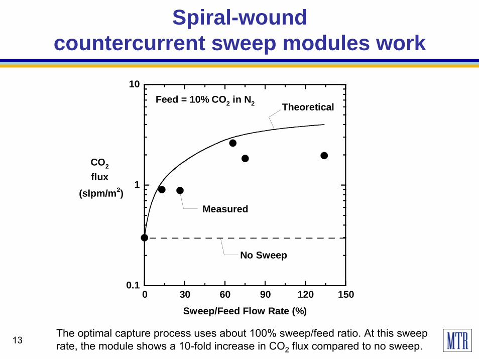
Spiral-wound countercurrent sweep modules work
The optimal capture process uses about 100% sweep/feed ratio. At this sweep rate, the module shows a 10-fold increase in CO2 flux compared to no sweep.
0.1
1
10
0 30 60 90 120 150Sweep/Feed Flow Rate (%)
CO2 flux
(slpm/m2)
Feed = 10% CO2 in N2
Measured
Theoretical
No Sweep

14
APS Red Hawk power plant• Uses 8-inch diameter Polaris™ membrane modules.
• Captured CO2 will be used for biofuels production.
Polaris™ membrane systems have proven field experience
BP Pascagoula • Conducted 3-month field test of 8-inch diameter
Polaris™ membrane modules.
• Removed CO2 and higher hydrocarbons from raw natural gas.

15
Cholla field test
• A 6-month field test of 8-inch diameter Polaris membrane modules at Cholla coal-fired plant is scheduled to begin in 4Q09.
• Key objectives are to demonstrate sweep operation in commercial-sized modules and to investigate membrane lifetime.
Skid footprint is 24’ x 7’250,000 scfd flue gas slipstreamCaptures 1 ton CO2/day

16
• Total energy use in plant is 56 MW; uses 5.5 MW water pumps.
• Plant produces 100 million m3/yr of fresh water.
Membrane plants of the required size exist today
Ashkelon desalination plant• 40,000 spiral-wound RO
membrane modules
• 1.5 million m2 membrane area

17
Efficient module packing and low-cost components reduce installed cost
About 130 mega-module skids would be required for a 600 MWe power plant.
Typical cost ($/m2) Type of unit High-pressure gas
separation (steel vessels) Reverse osmosis (plastic vessels)
Membrane 20 5
Membrane modules 100 10-15
Installed modules in a skid 570 20-50

18
Advantages and challenges
• Particulate matter and its potential impact on membrane lifetime• Energy losses due to feed and permeate side pressure drops• Cost reduction and device scale-up issues• Integration with power plants and effect of recycle on boiler• Lack of operating experience in the power industry
• Simple operation; no chemical reactions, no moving parts
• Tolerance to high levels of wet acid gases; inert to oxygen
• Compact and modular with a small footprint
• Low energy use; no additional water used (recovers water from flue gas)
• Builds on existing, low-cost technology already used at a similar scale
Advantages:
Challenges:

19
Future plans beyond the current project
Develop plans for a 50-100 ton CO2/day system
Include CO2 liquefaction section
Incorporate low-cost components (target $150/m2)
Explore options for testing air recycle to boiler
20
Summary
• Earlier project demonstrated the potential of high permeance membranes and a novel process design to cost-effectively capture CO2 from coal-fired flue gas.
• Operating experience with real flue gas is critical. The upcoming field test at Cholla will be a key test of the membrane approach.
• The scale-up and cost reduction roadmap can be modeled on existing membrane technology.
• Next step is a 10-fold larger system that demonstrates low-cost components and CO2 liquefaction.

21
Acknowledgements
• DOE NETL – Heino Beckert, Jose Figueroa• APS – Ray Hobbs, Xiaolei Sun• EPRI – Abhoyjit Bhown, Brice Freeman, Dick Rudy,
George Offen

22
Extras

23

24
Why doesn’t high membrane selectivity help?
• high selectivity demands high membrane area.
• increasing the pressure ratio is energy intensive.
0
20
40
60
80
100
0 0.1 0.2 0.3 0.4 0.5 0.6 0.7
Permeate CO2
concentration(%)
Permeate pressure (bar)
Feed = 13% CO2 at 1.1 bar
α = 50
membrane selectivity(α ) = 500
Minimum practical permeate pressure(pressure ratio =10)
Understanding membrane process design is important to direct materials development
The separation is pressure ratio limited, and

25
The importance of pressure ratio
For this example,
• the concentration of CO2 in the permeate can never exceed 50% no matter how selective the membrane
• At least half the permeate must be the slow component (N2)
• Permeation of the slow component determines the membrane area
• Infinite selectivity = no slow component permeation = infinite membrane area
Permeate0.2 bar; 50% CO2
PCO2 = 50% of 0.2 bar = 0.1 bar
Feed1 bar; 10% CO2
PCO2= 10% of 1 bar = 0.1 bar
50% 110% 0.2
feed
permeate
Ppermeateconcfeed conc P
barbar
⎛ ⎞⎛ ⎞ ≤ ⎜ ⎟⎜ ⎟⎝ ⎠ ⎝ ⎠
⎛ ⎞ ⎛ ⎞≤⎜ ⎟ ⎜ ⎟⎝ ⎠ ⎝ ⎠
Membraneenrichment
Pressureratio≤

26
Would a membrane with higher selectivity help?
0
20
40
60
80
100
0 0.1 0.2 0.3 0.4 0.5 0.6 0.7
Permeate CO2
concentration(%)
Permeate pressure (bar)
Feed = 13% CO2 at 1.1 bar
α = 50
α = 500
Minimum practical permeate pressure(pressure ratio =10)
No! The separation is pressure ratio limited, and high selectivity demands high membrane area
0
5
10
15
20
10 100 1000
Relative membrane
area
Membrane selectivity (CO 2/N2)
Feed = 13% CO2 at 1.1 barpermeate = 0.11 barpressure ratio = 10

27
Polaris™ membranes are extremely permeable to CO2
10
20
30
40
50
60
100 1,000 10,000
CO2/N2selectivity
CO2 permeance (gpu)
Polaris 1
Polaris 2
Polaris 3
Target area identified from
design calculations
Commercial CA membranes
Pure-gas data at 25°C and 50 psig feed pressure

28
• Initial 2-year project (4/1/07 to 3/31/09) investigated the feasibility of new polymer membranes to cost-effectively capture CO2 from flue gas.
• All objectives were met within time and budget; key findings include:
– Membranes can be fabricated into commercial modules; membrane permeance is 10x higher than existing materials and stability in acid gases looks good.
– For a real-world membrane system, membrane permeance is much more important than selectivity.
– Novel design shows promise to capture 90% CO2 using <15% of plant energy.
• New 2-year, $4.4 million project (10/1/08-9/30/10) with EPRI and APS will field demonstrate the membrane process with commercial-sized components; key objectives are:
– Run a 6-month field test at APS’s Cholla coal-fired power plant.
– With EPRI, conduct a comparative economic analysis of the proposed process.
– Develop low-cost component prototypes and a cost reduction roadmap.
– Investigate scale-up issues and begin plans for next-stage, 10x larger demonstration.
Project overview
29
Key remaining challenges to be addressed in the current project
• Particulate matter and its potential impact on membrane lifetime
• Energy losses due to feed and permeate side pressure drops
• Cost reduction and device scale-up issues
• Lack of operating experience