Embed Size (px)
Citation preview

The British Hydropower Association
A GUIDE TO UK MINI-HYDRO DEVELOPMENTS
© The British Hydropower Association All rights reserved. No part of this document may be reproduced, stored in a retrieval system, or transmitted, in any form or by any means, electronic, photocopying, recording or otherwise without
the prior permission of The British Hydropower Association.

British Hydropower Association A GUIDE TO UK MINI-HYDRO DEVELOPMENT v3.0
A Guide to UK mini-hydro development v3.0 1 09/10/12
A GUIDE TO UK MINI-HYDRO DEVELOPMENTS
CONTENTS
1. INTRODUCTION .................................................................................................................. 2
1.1 OVERVIEW ............................................................................................................................. 2 1.2 WHY MINI-HYDRO ? ................................................................................................................. 2
2. HYDROPOWER BASICS ....................................................................................................... 3
2.1 HEAD AND FLOW .................................................................................................................... 3 2.2 POWER AND ENERGY ................................................................................................................ 3 2.3 MAIN ELEMENTS OF A SCHEME .................................................................................................... 4 2.4 DIFFERENT SITE LAYOUTS .......................................................................................................... 5
3. ESSENTIAL INFORMATION ABOUT YOUR SITE .................................................................. 6
3.1 SUMMARY .............................................................................................................................. 6 3.2 FLOW ................................................................................................................................... 6 3.3 HEAD ................................................................................................................................... 9 3.4 PRELIMINARY POWER AND ENERGY CALCULATION ........................................................................... 10 3.5 USE OF THE LAND .................................................................................................................. 11 3.6 GRID-CONNECT OR STAND-ALONE .............................................................................................. 11
4. COMMISSIONING A FEASIBILITY STUDY ........................................................................ 12
4.1 PRELIMINARIES ..................................................................................................................... 12 4.2 FEASIBILITY ......................................................................................................................... 13 4.3 ENVIRONMENTAL IMPACT ......................................................................................................... 14
5. PLANNING AND LICENSES ............................................................................................... 16
5.1 WHOM TO CONSULT ............................................................................................................... 16 5.2 PLANNING ISSUES .................................................................................................................. 17 5.3 ENVIRONMENTAL ISSUES ......................................................................................................... 17
6. COSTS AND ECONOMICS .................................................................................................. 19
6.1 INVESTMENT COSTS ............................................................................................................... 19 6.2 RUNNING COSTS ................................................................................................................... 19 6.3 MAXIMISING THE REVENUE FROM YOUR SCHEME ............................................................................ 20 6.4 FINANCIAL ASSISTANCE .......................................................................................................... 21
7. CONTRACTING A SCHEME ................................................................................................ 23
7.1 DEVELOPMENT OPTIONS ......................................................................................................... 23 7.2 SUPPLIERS ........................................................................................................................... 23 7.3 INSTALLERS ......................................................................................................................... 24 7.4 COMMISSIONING AND HANDOVER ............................................................................................... 24 7.5 OPERATING THE SCHEME ......................................................................................................... 25
8. TECHNOLOGY ................................................................................................................... 26
8.1 OVERVIEW ........................................................................................................................... 26 8.2 MODERN TURBINE-TYPES ........................................................................................................ 28 8.3 TURBINE EFFICIENCY .............................................................................................................. 29 8.4 SCREENING .......................................................................................................................... 31 8.5 CONTROL ............................................................................................................................ 34
9. FURTHER INFORMATION AND ASSISTANCE .................................................................... 35
9.1 THE BHA ............................................................................................................................ 35 9.2 REFERENCE BOOKS ................................................................................................................ 35 9.3 INTERNET LINKS ................................................................................................................... 35 9.4 TERMINOLOGY ...................................................................................................................... 36
This Guide is available for download at: www.british-hydro.org
British Hydropower Association A GUIDE TO UK MINI-HYDRO DEVELOPMENT v3.0
A Guide to UK mini-hydro development v3.0 2 09/10/12
1. INTRODUCTION
1.1 Overview
This Guide is designed to assist anyone in the UK who is planning to develop a small-scale hydro-electric scheme. It has been prepared by the British Hydropower Association in order to support and encourage new developments in this sector. The term used in this Guide will be “Mini-hydro”, which can apply to sites ranging from a few kilowatts to electrifying a single home, to hundreds of kilowatts for selling into the National Grid. The Guide will explain:
• The basic concept of generating power from water • The purpose of different components of a scheme • The principle steps in developing a project • The technology involved • Where to go for help
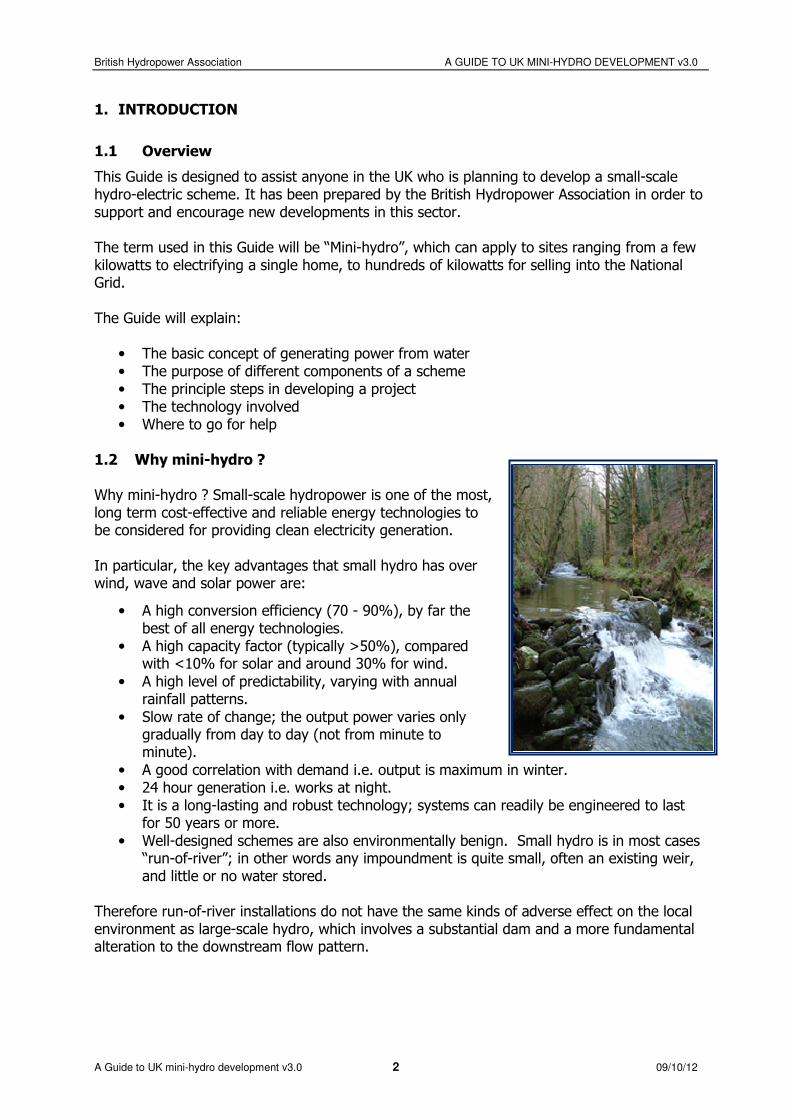
1.2 Why mini-hydro ? Why mini-hydro ? Small-scale hydropower is one of the most, long term cost-effective and reliable energy technologies to be considered for providing clean electricity generation. In particular, the key advantages that small hydro has over wind, wave and solar power are:
• A high conversion efficiency (70 - 90%), by far the best of all energy technologies.
• A high capacity factor (typically >50%), compared with <10% for solar and around 30% for wind.
• A high level of predictability, varying with annual rainfall patterns.
• Slow rate of change; the output power varies only gradually from day to day (not from minute to minute).
• A good correlation with demand i.e. output is maximum in winter. • 24 hour generation i.e. works at night. • It is a long-lasting and robust technology; systems can readily be engineered to last
for 50 years or more.
• Well-designed schemes are also environmentally benign. Small hydro is in most cases “run-of-river”; in other words any impoundment is quite small, often an existing weir, and little or no water stored.
Therefore run-of-river installations do not have the same kinds of adverse effect on the local environment as large-scale hydro, which involves a substantial dam and a more fundamental alteration to the downstream flow pattern.
British Hydropower Association A GUIDE TO UK MINI-HYDRO DEVELOPMENT v3.0
A Guide to UK mini-hydro development v3.0 3 09/10/12
2. HYDROPOWER BASICS
2.1 Head and Flow
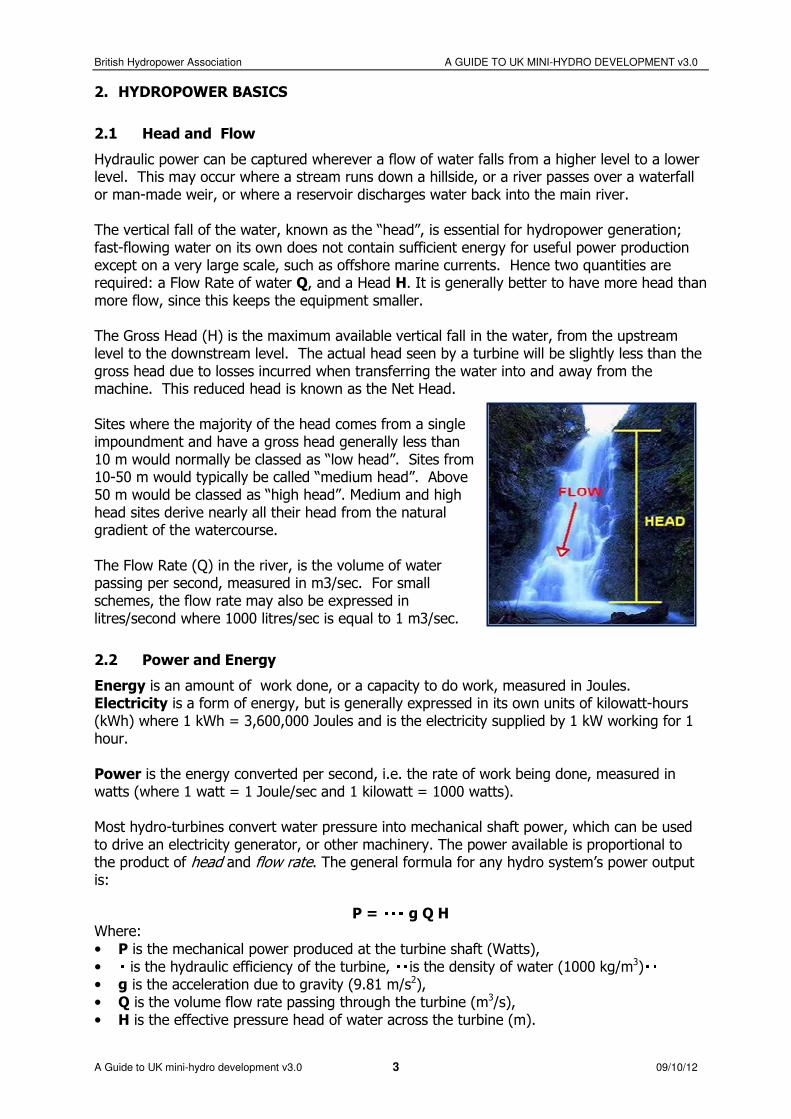
Hydraulic power can be captured wherever a flow of water falls from a higher level to a lower level. This may occur where a stream runs down a hillside, or a river passes over a waterfall or man-made weir, or where a reservoir discharges water back into the main river. The vertical fall of the water, known as the “head”, is essential for hydropower generation; fast-flowing water on its own does not contain sufficient energy for useful power production except on a very large scale, such as offshore marine currents. Hence two quantities are required: a Flow Rate of water Q, and a Head H. It is generally better to have more head than more flow, since this keeps the equipment smaller. The Gross Head (H) is the maximum available vertical fall in the water, from the upstream level to the downstream level. The actual head seen by a turbine will be slightly less than the gross head due to losses incurred when transferring the water into and away from the machine. This reduced head is known as the Net Head. Sites where the majority of the head comes from a single impoundment and have a gross head generally less than 10 m would normally be classed as “low head”. Sites from 10-50 m would typically be called “medium head”. Above 50 m would be classed as “high head”. Medium and high head sites derive nearly all their head from the natural gradient of the watercourse. The Flow Rate (Q) in the river, is the volume of water passing per second, measured in m3/sec. For small schemes, the flow rate may also be expressed in litres/second where 1000 litres/sec is equal to 1 m3/sec.
2.2 Power and Energy
Energy is an amount of work done, or a capacity to do work, measured in Joules. Electricity is a form of energy, but is generally expressed in its own units of kilowatt-hours (kWh) where 1 kWh = 3,600,000 Joules and is the electricity supplied by 1 kW working for 1 hour. Power is the energy converted per second, i.e. the rate of work being done, measured in watts (where 1 watt = 1 Joule/sec and 1 kilowatt = 1000 watts). Most hydro-turbines convert water pressure into mechanical shaft power, which can be used to drive an electricity generator, or other machinery. The power available is proportional to the product of head and flow rate. The general formula for any hydro system’s power output is:
P = g Q H Where:
• P is the mechanical power produced at the turbine shaft (Watts), • is the hydraulic efficiency of the turbine, is the density of water (1000 kg/m3) • g is the acceleration due to gravity (9.81 m/s2), • Q is the volume flow rate passing through the turbine (m3/s), • H is the effective pressure head of water across the turbine (m).
British Hydropower Association A GUIDE TO UK MINI-HYDRO DEVELOPMENT v3.0
A Guide to UK mini-hydro development v3.0 4 09/10/12
The best turbines can have hydraulic efficiencies in the range 80% to over 90% (higher than all other prime movers), although this will reduce with size. The smaller micro-hydro systems (<50kW) tend to be 70 to 80% efficient. After the turbine, there will be further losses in the speed-increaser (gearbox or belt-drive, if required) and the electrical generator, leading to an overall system efficiency in the range 60 to 80%. If we take 70% as a typical water-to-wire efficiency for the whole system, then the above equation simplifies to:
P (kW) = 7 × Q (m3/s) × H (m)
2.3 Main elements of a scheme
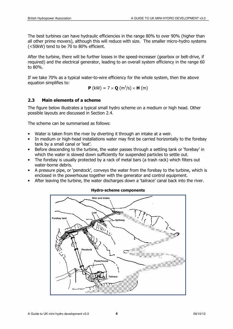
The figure below illustrates a typical small hydro scheme on a medium or high head. Other possible layouts are discussed in Section 2.4. The scheme can be summarised as follows: • Water is taken from the river by diverting it through an intake at a weir. • In medium or high-head installations water may first be carried horizontally to the forebay
tank by a small canal or ‘leat’.
• Before descending to the turbine, the water passes through a settling tank or ‘forebay’ in which the water is slowed down sufficiently for suspended particles to settle out.
• The forebay is usually protected by a rack of metal bars (a trash rack) which filters out water-borne debris.
• A pressure pipe, or ‘penstock’, conveys the water from the forebay to the turbine, which is enclosed in the powerhouse together with the generator and control equipment.
• After leaving the turbine, the water discharges down a ‘tailrace’ canal back into the river.
Hydro-scheme components
Weir and intake
Forebay tank
Penstock
Leat
Tailrace
Powerhouse
Spillway
British Hydropower Association A GUIDE TO UK MINI-HYDRO DEVELOPMENT v3.0
A Guide to UK mini-hydro development v3.0 5 09/10/12
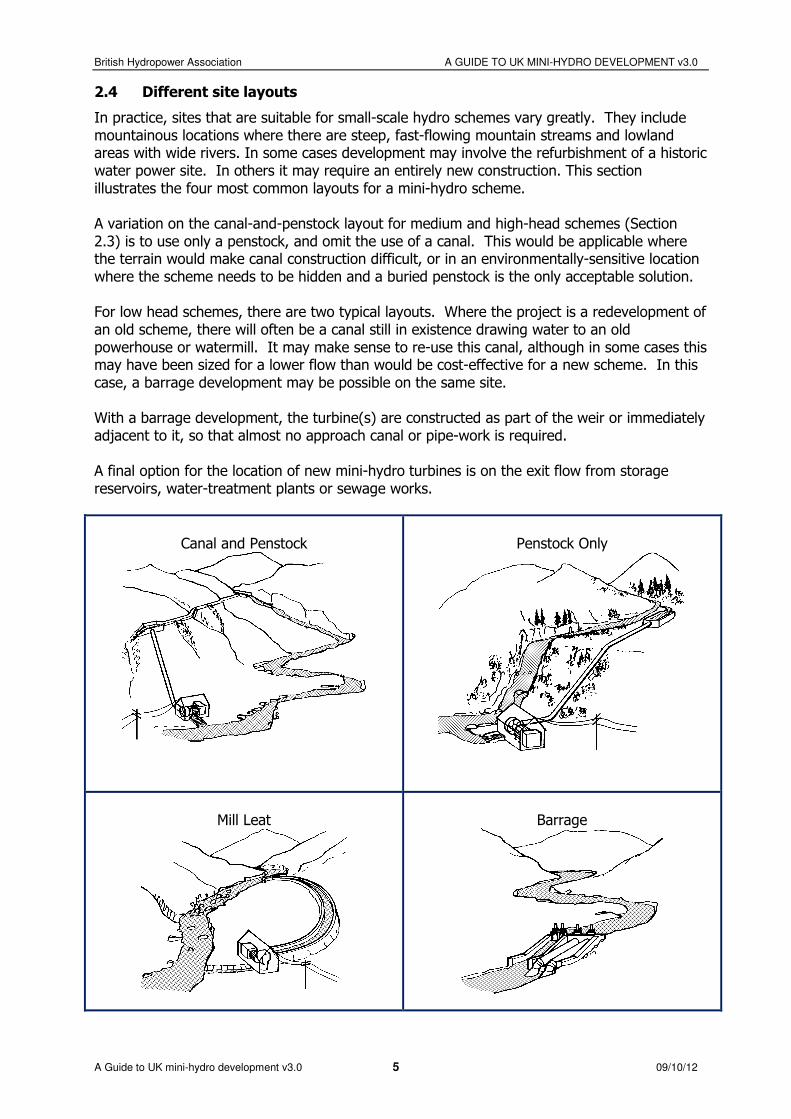
2.4 Different site layouts
In practice, sites that are suitable for small-scale hydro schemes vary greatly. They include mountainous locations where there are steep, fast-flowing mountain streams and lowland areas with wide rivers. In some cases development may involve the refurbishment of a historic water power site. In others it may require an entirely new construction. This section illustrates the four most common layouts for a mini-hydro scheme. A variation on the canal-and-penstock layout for medium and high-head schemes (Section 2.3) is to use only a penstock, and omit the use of a canal. This would be applicable where the terrain would make canal construction difficult, or in an environmentally-sensitive location where the scheme needs to be hidden and a buried penstock is the only acceptable solution. For low head schemes, there are two typical layouts. Where the project is a redevelopment of an old scheme, there will often be a canal still in existence drawing water to an old powerhouse or watermill. It may make sense to re-use this canal, although in some cases this may have been sized for a lower flow than would be cost-effective for a new scheme. In this case, a barrage development may be possible on the same site. With a barrage development, the turbine(s) are constructed as part of the weir or immediately adjacent to it, so that almost no approach canal or pipe-work is required. A final option for the location of new mini-hydro turbines is on the exit flow from storage reservoirs, water-treatment plants or sewage works.
Canal and Penstock
Penstock Only
Mill Leat
Barrage
British Hydropower Association A GUIDE TO UK MINI-HYDRO DEVELOPMENT v3.0
A Guide to UK mini-hydro development v3.0 6 09/10/12
3. ESSENTIAL INFORMATION ABOUT YOUR SITE
3.1 Summary
There are a few pieces of essential information that need to be obtained when a new site is being considered for hydro generation. 1. Firstly, one has to identify whether there is a significant energy resource. This involves
estimating or measuring the flow and available head, and estimating what annual energy capture would result.
2. If the potential output of a scheme is attractive, then one needs to be confident that (i)
permission will be granted to use all of the land required both to develop the scheme and to have the necessary access to it, and (ii) the necessary environmental licences will be granted to divert the required flow from the watercourse.
3. Finally, there needs to be a clear destination for the power: is there a nearby load that needs to be supplied, or is there a convenient point of connection into the local distribution network?
These issues are explored in more detail below.
3.2 Flow
3.2.1 Obtaining Flow Data
In England and Wales, the Environment Agency measures the flow in most significant rivers and streams in the UK, and data from the 1300 gauging stations can be obtained from the National River Flow Archive. Data for hundreds of sites is available over the internet, at: www.ceh.ac.uk/data/nrfa/index.html. These records can be used to assess stream flow at the proposed site, as long as due allowance is made for the actual site location in relation to the gauging station (upstream or downstream). If no data is available, it is also possible to use hydrological methods that are based on long-term rainfall and evaporation records, and on discharge records for similar catchment areas. This allows initial conclusions to be drawn on the overall hydraulic potential without taking actual site observations. For small catchment areas (e.g. less than 5km²) It is advisable to follow this up with site measurements once the project looks likely to be feasible. The reference books included in the bibliography offer a number of more or less sophisticated methods both for estimating the hydrology of a catchment area and for measuring the flow in streams. For smaller streams, the most accurate and reliable flow measurement method is to install a flow-gauging weir, as summarised below.

British Hydropower Association A GUIDE TO UK MINI-HYDRO DEVELOPMENT v3.0
A Guide to UK mini-hydro development v3.0 7 09/10/12
3.2.2 Gauging Weirs
A flow-gauging weir has a rectangular (or triangular) notch in it through which all the water in the stream flows. It is useful typically for flows in the region of 50-1000 l/s. The flow rate can be determined from a single reading of the difference in height between the upstream water level and the bottom of the notch (see Figure). For reliable results, the crest of the weir must be kept 'sharp' and sediment must be prevented from accumulating behind the weir. The formula for a rectangular notched weir is:
5.1
d h)h2.0L(g2C3
2Q −=
where: Q = flow rate (m3/s) Cd = the coefficient of discharge L = the notch width (m) h = the head difference (m) g = acceleration due to gravity (9.81m/s2) If Cd is taken, typically, as 0.6, then the equation becomes: Q = 1.8 (L - 0.2h) h1.5 Since stream flow varies both from day to day and with the season, measurements should ideally be taken over a long period of time, preferably at least a year, and correlated against the prevailing rainfall vs. long-term rainfall records to establish how the measured flows would relate to an ‘average’ year.
Flow-Gauging Weir

British Hydropower Association A GUIDE TO UK MINI-HYDRO DEVELOPMENT v3.0
A Guide to UK mini-hydro development v3.0 8 09/10/12
3.2.3 Flow Duration Curve
There are two ways of expressing the variation in river flow over the year: the annual hydrograph and the Flow Duration Curve or FDC, as illustrated below. The annual hydrograph is the easiest to understand, since it simply shows the day-by-day variation in flow over a calendar year. However, the FDC is more useful when calculating the energy available for a hydro-power scheme. The FDC shows how flow is distributed over a period (usually a year). The vertical axis gives the flow, the horizontal axis gives the percentage of the year that the flow exceeds the value given on the y-axis. Hence, for example, the FDC can immediately indicate the level of flow that will be available for at least 50% of the year (known as Q50). The flow exceeded for 95% of the year (Q95) is often taken as the characteristic value for minimum river flow. FDCs are often very similar for a region, but can be affected by soil conditions, vegetation cover, and to a lesser extent by catchment shape. They are also modified by man-made reservoirs, abstractions and discharges. A flatter FDC (characterising a heavily spring-fed river) is preferable to a steeply sloping one, and means that the total annual flow will be spread more evenly over the year, giving useful flow for a longer period, and less severe floods.
Compensation Flow A portion of the flow, historically called the compensation flow (but now also referred to as the ‘residual’, ‘reserved’, ‘prescribed’ or ‘hands-off’ flow), will need to by-pass the scheme for aesthetic or environmental reasons. In schemes where water is diverted from the main course of the river this compensation flow is needed to maintain the ecology and aesthetic appearance of the river in the depleted stretch. The amount of compensation flow will depend on site-specific factors, but a reasonable first estimate will lie between the Q85 and Q95 values of river flow. If there is no depleted reach, it may be possible to agree a value less than Q95.
Annual Hydrograph
Flow Duration Curve
British Hydropower Association A GUIDE TO UK MINI-HYDRO DEVELOPMENT v3.0
A Guide to UK mini-hydro development v3.0 9 09/10/12
3.3 Head
3.3.1 Head measurements
The head of water available at any one site can be determined by measuring the height difference between the water surface at the proposed intake and the water surface at the point where the water will be returned. A number of reference books can provide details of basic survey techniques to measure or estimate the available head. The most common methods are summarised as follows:
1. An initial estimate for a high-head site (> 50m) can be taken from a large-scale map, simply by counting the contours between the inlet and discharge points: the distance between contours on standard Ordnance Survey maps is usually 10m, but can be 5m.
2. Altimeters can also be useful for high-head pre-feasibility studies. Surveying altimeters
in experienced hands will give errors of as little as 3% in 100m. Atmospheric pressure variations need to be corrected for, however, and several readings should be taken on different days to give confidence.
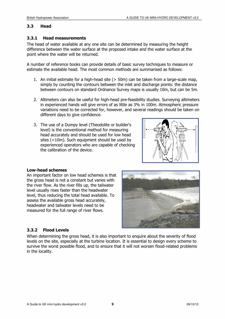
3. The use of a Dumpy level (Theodolite or builder's level) is the conventional method for measuring head accurately and should be used for low head sites (<10m). Such equipment should be used by experienced operators who are capable of checking the calibration of the device.
Low-head schemes An important factor on low head schemes is that the gross head is not a constant but varies with the river flow. As the river fills up, the tailwater level usually rises faster than the headwater level, thus reducing the total head available. To assess the available gross head accurately, headwater and tailwater levels need to be measured for the full range of river flows.
3.3.2 Flood Levels
When determining the gross head, it is also important to enquire about the severity of flood levels on the site, especially at the turbine location. It is essential to design every scheme to survive the worst possible flood, and to ensure that it will not worsen flood-related problems in the locality.
British Hydropower Association A GUIDE TO UK MINI-HYDRO DEVELOPMENT v3.0
A Guide to UK mini-hydro development v3.0 10 09/10/12
3.4 Preliminary power and energy calculation
3.4.1 Design Flow
It is unlikely that low-head schemes using significantly more than the mean river flow (Qmean) will be economically attractive. Therefore the turbine design flow for a run-of-river scheme (a scheme operating with no appreciable water storage) will not normally be greater than Qmean. For medium and high head schemes on ‘flashy’ watercourses, higher design flows can be
economically and environmentally justified, and design flows as high as 1.5 × Qmean can prove to be optimum. The greater the chosen value of the design flow, the smaller the proportion of the year that the system will be operating on full power, i.e. it will have a lower ‘Capacity factor’.
3.4.2 Capacity Factor
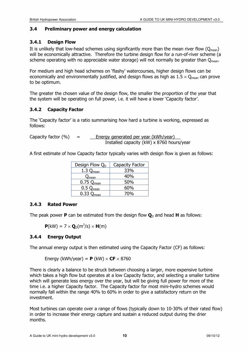
The ‘Capacity factor’ is a ratio summarising how hard a turbine is working, expressed as follows: Capacity factor (%) = Energy generated per year (kWh/year) Installed capacity (kW) x 8760 hours/year A first estimate of how Capacity factor typically varies with design flow is given as follows:
Design Flow QD Capacity Factor
1.3 Qmean 33%
Qmean 40%
0.75 Qmean 50%
0.5 Qmean 60%
0.33 Qmean 70%
3.4.3 Rated Power
The peak power P can be estimated from the design flow QD and head H as follows:
P(kW) = 7 × QD(m3/s) × H(m)
3.4.4 Energy Output
The annual energy output is then estimated using the Capacity Factor (CF) as follows:
Energy (kWh/year) = P (kW) × CF × 8760 There is clearly a balance to be struck between choosing a larger, more expensive turbine which takes a high flow but operates at a low Capacity factor, and selecting a smaller turbine which will generate less energy over the year, but will be giving full power for more of the time i.e. a higher Capacity factor. The Capacity factor for most mini-hydro schemes would normally fall within the range 40% to 60% in order to give a satisfactory return on the investment. Most turbines can operate over a range of flows (typically down to 10-30% of their rated flow) in order to increase their energy capture and sustain a reduced output during the drier months.

British Hydropower Association A GUIDE TO UK MINI-HYDRO DEVELOPMENT v3.0
A Guide to UK mini-hydro development v3.0 11 09/10/12
3.5 Use of the Land
No project can proceed unless you have the right to utilise all the land needed to build it. It is also important to establish how contractors will access the different parts of the scheme with the necessary equipment, and to confirm that these routes will be available. It is therefore wise to approach the relevant land-owners at an early stage to establish any objections to the proposed scheme and to negotiate access. Since water courses often form property boundaries, the ownership of the banks and existing structures may be complex. Failure to settle this issue at an early stage may result in delays and cost penalties later in a project. Legally binding leasing agreements will need to be drawn up which establish your right to use the necessary land areas and also to define your responsibilities, as a tenant, in maintaining it. For example, the operator of a scheme may be required to take on the maintenance liability of an existing weir and mill leat as part of the agreement allowing him to install a turbine in the old mill.
3.6 Grid-connect or stand-alone
It is important to determine at the outset what the value of the electricity generated by the scheme will be, i.e. to whom the power will be sold. The electricity generated by a scheme may be used at the point of generation, in place of electricity supplied by the local electricity company. In addition, any excess power may be exported into the local distribution network by agreement with the Distribution Network Operator (DNO). It is always financially advantageous to consume as much of the power as possible on site, and only export the surplus into the network. If the scheme is to produce power for export to the local network, there should be early discussions with the DNO who will specify the system protection and metering equipment, and will also provide an estimate of connection costs and the best location for feeding into their system.
British Hydropower Association A GUIDE TO UK MINI-HYDRO DEVELOPMENT v3.0
A Guide to UK mini-hydro development v3.0 12 09/10/12
4. COMMISSIONING A FEASIBILITY STUDY
4.1 Preliminaries
4.1.1 Getting Professional Help
Any developer should seek independent professional advice before committing significant finance to the design and construction of a small-scale hydro scheme. The involvement of professionals in a small-scale hydro development can range from preliminary site assessment, through the conducting of a feasibility study, to a full ‘turnkey’ service, handling every aspect of a development. In addition, there are several companies that lease, develop and operate sites as a business activity, and can provide a full skills and finance package. Some turbine suppliers will offer feasibility services as a loss-leader to procuring an equipment order. If you are seeking fully independent advice, it is important to check whether your adviser is linked to any specific suppliers.
4.1.2 Preliminary Site Assessment
An experienced hydro professional should be able to indicate whether a site is worth considering further, on the basis of an initial site visit and discussions with the developer and others. Preliminary investigations of this type will typically require no more than 2-3 days’ work and will cost in the region of £1000 - £1500. A relatively minor investment at this stage could save much greater expense and potential complications later in the development process. The main issues that should be considered in a preliminary investigation are:
• The existence of a suitable waterfall or weir and a turbine site • A consistent flow of water at a usable head • The likely acceptability of diverting water to a turbine • Suitable site access for construction equipment • A nearby demand for electricity, or the prospect of a grid connection at reasonable cost • The social and environmental impact on the local area • Land ownership and/or the prospect of securing or leasing land for the scheme at a
reasonable cost • Outline scheme layout and equipment specifications • An initial indication of design power, annual energy output and revenue • Ball-park costs for developing the scheme The accuracy of the information may only be plus or minus 25%, however, this should be sufficient for deciding whether to proceed to a more detailed feasibility study.

British Hydropower Association A GUIDE TO UK MINI-HYDRO DEVELOPMENT v3.0
A Guide to UK mini-hydro development v3.0 13 09/10/12
4.2 Feasibility
A feasibility study uses accurate data, develops design drawings and looks closely at costs. It can take the project forward from the initial idea to a final design that will support applications for project finance and the necessary licenses. It is therefore always wise to employ a professional to conduct the feasibility study and the detailed design work. The cost of a full feasibility study carried out by an independent consultant depends on its scope and on the specific characteristics of the site, but would typically be £5,000-£10,000. For a domestic-scale scheme (i.e. less than 15 kW), a detailed feasibility may not be affordable, and a less detailed ‘Design Study’ may prove sufficient. This would cover the same basic ground but use approximate data analysed less extensively. It should be possible to commission a basic design study for less than £5000. The following essential tasks should form components of a feasibility, or design, study: 1. Hydrological Survey. Typically, a hydrological survey would produce a flow duration
curve. This would be based on long-term records of rainfall and/or flow data, together with a knowledge of the catchment geology and soil types. This long-term information might be backed up by short-term flow measurements. The study should include a recommendation for the required compensation flow.
2. System design. This would include a description of the overall project layout, including a drawing showing the general arrangement of the site. The prominent aspects of the works should be described in detail, with appropriate drawings, covering: • Civil works (intake and weir, intake channel, penstock, turbine house, tailrace channel,
site access, construction details)
• The generating equipment (turbine, gearbox, generator, control system) and machinery layout
• Grid connection
3. System costing. A clear system costing would include a detailed estimate of the capital costs of the project, subdivided into:
• Civil costs • The cost of grid-connection • The cost of electro-mechanical equipment • Engineering and project management fees
4. Estimate of energy output and annual revenue. This would summarise the source
data (river flows, hydraulic losses, operating head, turbine efficiencies and methods of calculation) and calculate the output of the scheme in terms of the maximum potential output power (in kW) and the average annual energy yield (kWh/year) converted into annual revenue (£/year)
An additional task, which may form part of the main feasibility report but is often undertaken separately, is the environmental assessment of the scheme, discussed in Section 4.3.

British Hydropower Association A GUIDE TO UK MINI-HYDRO DEVELOPMENT v3.0
A Guide to UK mini-hydro development v3.0 14 09/10/12
4.3 Environmental impact
4.3.1 The Environmental Statement
Some form of environmental assessment is essential when it comes to applying for planning permission and environmental licenses. Under the Town and Country Planning (Assessment of Environmental Effects) Regulations 1988, the planning application for any development that the planning authority considers likely to have a significant impact on the environment must be accompanied by an Environmental Statement. This document provides an assessment of the project’s likely environmental effects, together with any design, construction, operational and decommissioning measures that are to be taken to minimise them. It would typically cover such issues as flora, fauna, noise levels, traffic, land use, archaeology, recreation, landscape, and air and water quality. 4.3.1 The Environmental Statement
The Environment Agency will also require a report assessing the environmental effects of the development. If the planning authority has asked for an Environmental Statement, this may meet the requirements of the Environment Agency. However, the Environment Agency may ask for environmental information even if the local planning authority does not. Such information might cover water use, water quality, fisheries, river ecology, flood defence, nature conservation, navigation and public recreation issues. The Environment Agency should be consulted at an early stage and will provide guidance on what is required. The Environment Agency 2012 requirements and advice on hydropower licensing is provided at: www.environment-agency.gov.uk/business/topics/water/32022.aspx SEPA also publish a guide to run of river hydropower schemes which is provided at: www.sepa.org.uk/waer/hydropower.aspx Specialist environmental consultants may be employed if project complexity merits their involvement. However, general hydro consultants with an appropriate track record may also undertake an assessment of this type.

British Hydropower Association A GUIDE TO UK MINI-HYDRO DEVELOPMENT v3.0
A Guide to UK mini-hydro development v3.0 15 09/10/12
4.3.2 Fisheries
Hydro-installations on rivers populated by migrating species of fish, such as salmon and sea trout, are subject to special requirements as defined in the Salmon and Freshwater Fisheries Act. Under the Act, migratory fish (salmon and sea trout) must not be ingested into the turbine (so the mesh of the trashrack must be fine enough), and there must be a water passage by-passing the hydro-plant at all times so that fish can migrate up or downstream. To allow fish to pass upstream sometimes requires the construction of a fish-pass, which may be a shallow ramp with baffles, or a series of pools such that fish can jump up from one pool to the next. There are additional requirements where eels are present, as dictated by the Eel Order 2009, which may require an eel-pass and/or specific screening.

British Hydropower Association A GUIDE TO UK MINI-HYDRO DEVELOPMENT v3.0
A Guide to UK mini-hydro development v3.0 16 09/10/12
5. PLANNING AND LICENSES
5.1 Whom to consult
Informal and formal consultation should underpin every stage of a development and may be handled either by the developer or by a hydro professional. Consultation will be tailored to each individual development. Some sites, for instance, may not be located on fishing rivers and therefore consultation with fisheries bodies or angling clubs would be limited. Similarly, where a site does not require planning permission, there is no need for detailed consultation with the relevant planning authorities. The bodies listed in the table below should be approached, as appropriate, at the outset of a development, and contact should be maintained throughout. Full consultation will ensure that any problems are identified at an early stage, and this may prevent the incurring of unnecessary expenditure.
Body to be consulted Purpose of Consultation
The Environment Agency (England and Wales) Scottish Environmental Protection Agency (SEPA)
To ensure that the site is acceptable To establish a design that is acceptable To identify the permissions required To discuss and agree an acceptable river operating regime (i.e. amount and timing of abstractions)
Relevant planning authority To ensure that the site is acceptable To establish a design that is acceptable, especially where construction work is needed To identify permissions required
Fisheries bodies or those with an interest in fisheries (e.g. angling clubs). Scotland: the District Salmon Fisheries Board
To address possible concerns at the design stage
Statutory environmental bodies e.g. Natural England, Countryside Commission for Wales, Scottish Natural Heritage
To address potential environmental impacts at the design stage
Landowners To address ownership, access and leasing issues, way-leaves for cables To address possible objections to development
Distribution Network Operator If an electricity connection is required, to establish any design constraints and connection costs If appropriate, to enter negotiations for electricity sale

British Hydropower Association A GUIDE TO UK MINI-HYDRO DEVELOPMENT v3.0
A Guide to UK mini-hydro development v3.0 17 09/10/12
5.2 Planning issues
Planning aspects of hydro developments are the responsibility of the local planning authority. Planning permission will be required for most hydro developments. A possible exception is the refurbishment of an existing scheme, where there is no ‘change of use’. The planning department will indicate whether planning permission is required and also whether other related procedures, such a Building Regulation Approval or the submission of an Environmental Statement, are necessary. As well as giving advice on how to make an application and on the fee charged, the planning department will also suggest who should be consulted, indicate sensitivities to development, and outline measures that might be taken to make developments more acceptable. An early approach to the planning department is recommended so that any uncertainties can be clarified and a good working relationship established. The primary issues of concern to the planners are likely to be:
• The visual appearance of the scheme, including the powerhouse and penstock in particular • Potential noise impacts on nearby residents • Disturbance during the construction phase, both to local residents and disrupting traffic • Preservation of structures of historical importance On environmental issues, the planners will normally take advice from their statutory consultees, such as the Environment Agency/SEPA and Natural England/Scottish Natural Heritage. They will also be able to advise on whether the scheme warrants a public display for the purpose of presenting the project to local people and helping allay any concerns. It is sometimes advisable to apply for outline planning permission in the first instance, in which the main elements of the scheme can be agreed but without the completion of the final design. This means that the overall planning process will be longer, but allows feedback received during the outline planning process to be accommodated more easily into the final design and therefore reduces the risk of the full planning application being rejected.
5.3 Environmental issues
5.3.1 Licences
All watercourses of any size are controlled by the Environment Agency/SEPA. To abstract water from them (even though it will be returned downstream) will almost certainly require their permission in the form of a licence. There are three licences that can apply to a hydropower scheme in England and Wales
• Abstraction Licence, if water is being diverted ‘away from the main line of flow of the river’. In practice, this means that the only type of scheme which can avoid an abstraction licence would be a barrage-type project where turbines are installed on an existing weir and the water remains between the existing banks of the river. All new abstraction licences are now time-limited to between 6 and 18 years, after which they must be renewed. The Environment Agency have stated that there will be a “presumption of renewal”, but this is clearly an area of risk for new developments.

British Hydropower Association A GUIDE TO UK MINI-HYDRO DEVELOPMENT v3.0
A Guide to UK mini-hydro development v3.0 18 09/10/12
• Impoundment Licence, if changes are being made to structures which impound water, such as weirs and sluices, or if new structures are to be built.
• Flood Defence Consent, for any works being carried out in, or adjacent to, a ‘main river’ The Environment Agency may also require a Section 158 Agreement to be drawn up, which defines certain further details on the way the scheme must be operated in order not to conflict with the Agency’s river management duties, e.g. rights of access, the control of river levels, flood waters, maintenance of the weir and river structures, etc.. In Scotland a single licence may be applied for under the Controlled Activities Regulations (CAR) this single licence will cover all aspects of the environmental licence required for a hydropower scheme of any size. If you believe the terms of the License you are issued are unfair or unsatisfactory, then it is possible to appeal the against conditions of the licence issued within 28 days.
5.3.2 Approaching the Environment Agency / SEPA
Beyond the licensing procedures, the Environment Agency and SEPA are also responsible for fish protection and other environmental aspects of any riverside development. Whilst they have a duty to protect the environment from harmful development, the Agency also has a statutory duty to promote sustainable development and to be proportionate in its requirements, bearing in mind the costs involved. In general: • approach the Agency at an early stage and maintain a dialogue with them • respect the fact that the Agency cannot compromise its statutory duties • maintain a flexible approach to the proposed scheme in respect of measures to mitigate its
impact, even where this may be at the expense of some generating capacity. The Agency will advise on the scope of any environmental assessments that may be needed. Schemes less than 500kW are not required by law to produce a formal Environmental Impact Assessment. However, all license applications normally need to be supported by an Environmental Report which summarises the details and impacts of the scheme. The Agency will provide the required scope of such a report. If you believe the Agency is not responding in a fair or efficient manner, then you should not hesitate to make a representation to the Area Manager or to the head of the Permitting Department.
British Hydropower Association A GUIDE TO UK MINI-HYDRO DEVELOPMENT v3.0
A Guide to UK mini-hydro development v3.0 19 09/10/12
6. COSTS AND ECONOMICS
6.1 Investment Costs
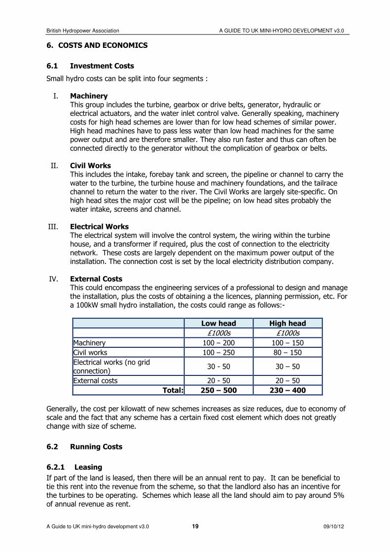
Small hydro costs can be split into four segments : I. Machinery
This group includes the turbine, gearbox or drive belts, generator, hydraulic or electrical actuators, and the water inlet control valve. Generally speaking, machinery costs for high head schemes are lower than for low head schemes of similar power. High head machines have to pass less water than low head machines for the same power output and are therefore smaller. They also run faster and thus can often be connected directly to the generator without the complication of gearbox or belts.
II. Civil Works This includes the intake, forebay tank and screen, the pipeline or channel to carry the water to the turbine, the turbine house and machinery foundations, and the tailrace channel to return the water to the river. The Civil Works are largely site-specific. On high head sites the major cost will be the pipeline; on low head sites probably the water intake, screens and channel.
III. Electrical Works The electrical system will involve the control system, the wiring within the turbine house, and a transformer if required, plus the cost of connection to the electricity network. These costs are largely dependent on the maximum power output of the installation. The connection cost is set by the local electricity distribution company.
IV. External Costs This could encompass the engineering services of a professional to design and manage the installation, plus the costs of obtaining a the licences, planning permission, etc. For a 100kW small hydro installation, the costs could range as follows:-
Low head High head
£1000s £1000s
Machinery 100 – 200 100 – 150
Civil works 100 – 250 80 – 150
Electrical works (no grid connection)
30 - 50 30 – 50
External costs 20 - 50 20 – 50
Total: 250 – 500 230 – 400
Generally, the cost per kilowatt of new schemes increases as size reduces, due to economy of scale and the fact that any scheme has a certain fixed cost element which does not greatly change with size of scheme.
6.2 Running Costs
6.2.1 Leasing
If part of the land is leased, then there will be an annual rent to pay. It can be beneficial to tie this rent into the revenue from the scheme, so that the landlord also has an incentive for the turbines to be operating. Schemes which lease all the land should aim to pay around 5% of annual revenue as rent.

British Hydropower Association A GUIDE TO UK MINI-HYDRO DEVELOPMENT v3.0
A Guide to UK mini-hydro development v3.0 20 09/10/12
6.2.2 Metering
Schemes over 30kW currently require half-hourly metering to be installed, which has to be monitored by an independent meter-reading company, although this requirement may change in the future. There is an annual charge to pay for this service, currently in the range £400 - £1000 / year.
6.2.3 Rates
Hydroelectric schemes which export the majority of their power into the network are subject to business rates, unless they are seen as being part of a domestic property. The rateable value is calculated by the Valuation Office according to various site parameters.
6.2.4 Maintenance and Servicing
Modern, automated equipment requires very little maintenance. The cost of routine inspections and an annual service should come to no more than 1-2% of the capital cost of the scheme. As the machine ages, there will eventually be extra costs associated with replacing seals and bearings, a new generator, refurbished sluice gates, etc., but these should not occur for at least 10 years.
6.2.5 Insurance
Although hydro plant is generally very reliable, the following insurances are recommended (and may be required by financiers):
• Material damage insurance against the cost of repairing damage to the works caused by fire and ‘special perils’ such as explosions, storms, flooding, impact and malicious damage
• Business interruption insurance against profit loss caused by fire or special perils damage • Public and employer’s liability insurances, which are required by law; a minimum
indemnity of £5 million is recommended.
6.3 Maximising the revenue from your scheme
Operators of renewable electricity-generating plant can generate revenue from:
• Selling the electricity itself • The Feed-in-Tariff • Levy Exemption Certificates
Selling Electricity If the electricity generated by a hydro-scheme is sold directly to an electricity company, then the price offered for the electricity itself is relatively small - in the range 4.5 – 6.0 p/kWh on average over the year. Alternatively, if there is a substantial electrical load close to where the power is being generated (e.g. factory or office complex), it will be more beneficial to use the hydropower to feed that load, so displacing electricity that would otherwise be bought in from the grid at perhaps 10 – 15 p/kWh. For smaller schemes, some electricity companies are willing to enter into a special contract which will balance the energy generated against the energy consumed on site on an annual or quarterly basis.

British Hydropower Association A GUIDE TO UK MINI-HYDRO DEVELOPMENT v3.0
A Guide to UK mini-hydro development v3.0 21 09/10/12
Furthermore, business customers who would otherwise have to pay the Climate Change Levy will make that additional saving on any hydroelectricity they buy from the scheme. 6.3 Maximising the revenue from your scheme
The Feed-in Tariff The UK Government introduced a new system for rewarding renewable generation in April 2010, known as the "Feed-in Tariff" or FiT. This provides an additional payment for each kWh generated, over and above the value of the electricity itself. The tariff to be paid depends upon the installed capacity of the scheme, with the following 5 tariff bands:
1. <15kW 2. 15 to 100 kW 3. 100 to 500 kW 4. 500 to 2000 kW 5. 2000 to 5000 kW
The Feed-in Tariff is index-linked and will last for 20 years from the registration date. The most up-to-date tariffs can be found at www.ofgem.gov.uk
It is also possible to attach a fixed export tariff to the Feed-in-Tariff, which will be paid on 75% of the total generation (known as the ‘deemed’ export). This avoids having to install an export meter and trade the electricity separately. However this tariff will always be lower than the open market price, so is aimed at the smaller schemes.
Levy Exemption Certificates (LECs) Green electricity which is sold into the grid will generate Levy Exemption Certificates (LECs) which can be sold on to business customers to enable them to avoid paying the full Climate Change Levy. The LECs can be sold for up to 90% of the Levy value.
Electricity Traders There are several options on who to approach to obtain the maximum income for your scheme. Not only will any one of the main electricity supply companies (Powergen, npower, etc.) make an offer for your output (including the FiTs, LECs, etc.), it is also possible to approach a range of specialist electricity trading companies which focus purely on getting the best price for renewable energy schemes. The BHA will be able to advise on which companies are offering the best deal for mini-hydro generation.
6.4 Financial Assistance
The Feed-in Tariff is now the principal public support for renewable energy schemes. Other assistance includes:
6.4.1 Tax breaks
• For domestic developers and other non-commercial owners, the government has reduced the VAT payable on hydro-electric plant to 5% for systems supplying buildings which are either residential or used for charitable purposes. Since many components of a hydro-scheme are not obviously “hydro-electric plant” on their own, the best advantage of this tax-break will be obtained by requesting a hydro installer to procure all hardware for the scheme which he can then genuinely pass on as part-and-parcel of the overall hydro-plant.

British Hydropower Association A GUIDE TO UK MINI-HYDRO DEVELOPMENT v3.0
A Guide to UK mini-hydro development v3.0 22 09/10/12
6.4.2 Grants
• There are a few local and regional funding mechanisms which can offer grants towards small-scale renewable energy projects, often to cover feasibility costs for community groups. District and County Councils should be able to advise on the availability of such funds.
NB: Accepting a grant toward the cost of developing your hydro project may rule it ineligible for FiTs

British Hydropower Association A GUIDE TO UK MINI-HYDRO DEVELOPMENT v3.0
A Guide to UK mini-hydro development v3.0 23 09/10/12
7. CONTRACTING A SCHEME
7.1 Development Options
7.1.1 Turnkey Contracts
Since any hydro scheme requires a substantial up-front investment, it is clearly essential that the project is implemented correctly and with robust engineering and equipment. For the larger schemes, requiring a hundreds of thousands of pounds investment, it will be important for the project to be managed by a professional hydro-engineering firm, and installed by an experienced contractor. The most common approach for implementing larger projects is the “turnkey contract” in which a single contractor takes on the entire scheme from start to finish. The contractor, who might be a civil engineering company or the turbine supplier, brings together a team of sub-contractors and suppliers under a single contract, typically following a competitive tendering process. From the owner’s point of view, this greatly simplifies the management of the job. However, since the main contractor is taking on most of the risks and unknowns, this will inevitably be reflected in the cost of the tender.
7.1.2 DIY
For the smaller schemes (generally less than 50 kW), it may be possible for the owner and his local team of contractors to share the tasks of implementing the scheme with the equipment supplier. This approach can lead to significant savings on the project cost, but requires the responsibilities of the different parties to be very clearly defined. Even if the owner is keen to adopt a DIY approach, there are certain activities where professional inputs will be essential to ensure the technical viability of the scheme. These areas can be summarised as follows:
1. The detailed site survey 2. The general layout of the scheme 3. The design of the intake 4. The layout of the powerhouse 5. The specification of the turbine and penstock 6. The installation and commissioning of the electro-mechanical equipment (which would
often be undertaken by the turbine supplier)
Therefore the main tasks which the scheme-owner may feel he can implement using local labour would be:
1. Construction of the intake works 2. Installation of the penstock pipe 3. Construction of the powerhouse and tailrace 4. Laying of electrical cabling
All of the above would be completed to a specification provided by the equipment supplier or hydro-power consultant.
7.2 Suppliers
Small-scale hydro power is a proven and mature technology. Reliable and efficient equipment and sound advice is available from a range of experienced suppliers and manufacturers in the UK and worldwide.

British Hydropower Association A GUIDE TO UK MINI-HYDRO DEVELOPMENT v3.0
A Guide to UK mini-hydro development v3.0 24 09/10/12
The term ‘supplier’ covers any company which will sell you equipment for your scheme. They may also be the manufacturer, or they may be the agent for imported equipment. Many turbine manufacturers will also offer to supply the full equipment package including the gearbox, generator, control panel, trashrack, sluice gate, etc. which they will assemble from their preferred sub-contractors. The BHA maintains a database of UK equipment suppliers. Another useful web-site for locating national and international suppliers is:
The International Journal of Hydropower and Dams (http://www.hydropower-dams.com/industryguide/)
Suppliers are usually willing to provide a ‘budget quote’ for the equipment for your scheme, based on limited information, in order to help you identify whether their equipment is appropriate and affordable without investing expensive resource. The minimum information they would need to respond to an enquiry would be the design head and flow. Additional useful information to include in such a request would be:
• Scheme location • Length and diameter of pressure pipe • Flow Duration Curve and compensation flow • Type of turbine required (if already known) • Any unusual constraints of the site e.g. environmental sensitivities
The typical lead time for a turbine, from placing an order to delivery on site, is between 6 and 10 months. This is an important consideration when planning the timescale of a development.
7.3 Installers
Installers are engineering companies who will manage the specification, procurement, installation and commissioning of all the components of a hydro-scheme. In essence, they will offer a turnkey project for the electro-mechanical aspects of the scheme. Most installers would also offer to undertake the site survey and initial feasibility work. Some installers may also take on the civil works, if relatively minor, otherwise a civil contractor will also be required to implement work to the installer’s specification. Installers for equipment under 15kW should be accredited under the MCS accreditation scheme The most reliable method for checking an installer’s credentials is to obtain references from previous work. Installers should be able to supply a list of past projects and the contact details of at least one recent customer. The BHA will be able to confirm whether an installer is a member of the Association and has a known track record in the industry.
7.4 Commissioning and handover
The final stage in the installation of a micro-hydro plant involves performance tests. The purpose is to check the function of the different components of the scheme and to measure

British Hydropower Association A GUIDE TO UK MINI-HYDRO DEVELOPMENT v3.0
A Guide to UK mini-hydro development v3.0 25 09/10/12
the overall system performance against the figures arrived at during the design of the scheme. Depending on the complexity of the system, it may take several months before all working conditions are experienced. Hence, although formal commissioning and hand-over may be completed in a few days, the end-user should not consider the job fully completed until satisfied that all operating conditions have been met. Important activities during commissioning will include:
• Ensuring sufficient flow is being drawn through the intake • Confirming that the channel can pass the design flow without undue head loss • Checking that surplus water passing through the intake will escape down the
appropriate spillways and will never overflow the channel walls
• Confirming that the design flow will pass down the pressure pipe without entraining air at the forebay
• Measuring the head loss in the pressure pipe • Checking the pipe joints for leaks • Confirming the smooth running of the turbine and generator, including checking the
bearings for noise and temperature
• Checking that belts and pulleys are correctly aligned, or that the gearbox is operating effectively without overheating
• Ensuring that the lubricating systems are working for the bearings and gearbox • Confirming that the turbine achieves its design power at rated head and flow • Checking all the functions of the control panel, in particular start-up and shut-down
sequences plus all the switchgear which interface and protect the system from the grid
7.5 Operating the scheme
Both the lifetime of the equipment and the level of effort required for operation and maintenance will depend on the project design, although small-scale hydro schemes tend to have long lifetimes and low maintenance costs. Modern schemes are usually automated, and regular maintenance is restricted to tasks such as the occasional clearing of the intake trash-rack and the lubrication of parts of the generating equipment. Older schemes may require more regular manual intervention, for instance daily raking of the trashrack and operating sluice gates or control valves. For schemes without an on-site or local operator, a remote monitoring system is recommended which will give a continuous update on system performance to a web-site, and provide an early indication of faults. During system commissioning, the installer should run through all the routine inspection and maintenance tasks with the owner of the scheme. He will also provide the documentation from the various equipment suppliers which should detail the relevant maintenance tasks and timings for each part of the system. If the electro-mechanical equipment is of modern design, only an annual service will be necessary. This can usually be carried out during the low-flow period when the plant is unlikely to be generating. It will typically be undertaken by the equipment supplier or the installer and will take about two days.
British Hydropower Association A GUIDE TO UK MINI-HYDRO DEVELOPMENT v3.0
A Guide to UK mini-hydro development v3.0 26 09/10/12
8. TECHNOLOGY
8.1 Overview
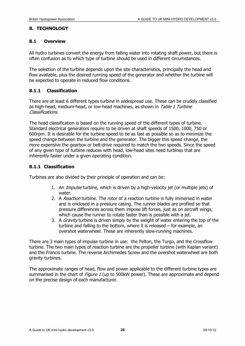
All hydro turbines convert the energy from falling water into rotating shaft power, but there is often confusion as to which type of turbine should be used in different circumstances. The selection of the turbine depends upon the site characteristics, principally the head and flow available, plus the desired running speed of the generator and whether the turbine will be expected to operate in reduced flow conditions.
8.1.1 Classification
There are at least 6 different types turbine in widespread use. These can be crudely classified as high-head, medium-head, or low-head machines, as shown in Table 1 Turbine Classifications. The head classification is based on the running speed of the different types of turbine. Standard electrical generators require to be driven at shaft speeds of 1500, 1000, 750 or 600rpm. It is desirable for the turbine speed to be as fast as possible so as to minimize the speed change between the turbine and the generator. The bigger this speed change, the more expensive the gearbox or belt-drive required to match the two speeds. Since the speed of any given type of turbine reduces with head, low-head sites need turbines that are inherently faster under a given operating condition. 8.1.1 Classification Turbines are also divided by their principle of operation and can be:
1. An Impulse turbine, which is driven by a high-velocity jet (or multiple jets) of water.
2. A Reaction turbine. The rotor of a reaction turbine is fully immersed in water and is enclosed in a pressure casing. The runner blades are profiled so that pressure differences across them impose lift forces, just as on aircraft wings, which cause the runner to rotate faster than is possible with a jet.
3. A Gravity turbine is driven simply by the weight of water entering the top of the turbine and falling to the bottom, where it is released – for example, an overshot waterwheel. These are inherently slow-running machines.
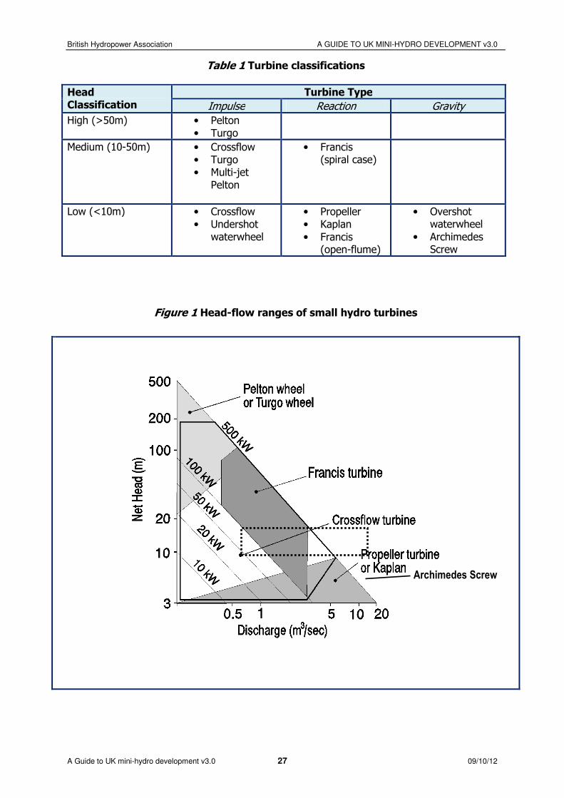
There are 3 main types of impulse turbine in use: the Pelton, the Turgo, and the Crossflow turbine. The two main types of reaction turbine are the propeller turbine (with Kaplan variant) and the Francis turbine. The reverse Archimedes Screw and the overshot waterwheel are both gravity turbines. The approximate ranges of head, flow and power applicable to the different turbine types are summarised in the chart of Figure 1 (up to 500kW power). These are approximate and depend on the precise design of each manufacturer.
British Hydropower Association A GUIDE TO UK MINI-HYDRO DEVELOPMENT v3.0
A Guide to UK mini-hydro development v3.0 27 09/10/12
Table 1 Turbine classifications
Head Classification
Turbine Type
Impulse Reaction Gravity
High (>50m) • Pelton • Turgo
Medium (10-50m) • Crossflow • Turgo • Multi-jet
Pelton
• Francis (spiral case)
Low (<10m) • Crossflow • Undershot
waterwheel
• Propeller • Kaplan
• Francis (open-flume)
• Overshot waterwheel
• Archimedes Screw
Figure 1 Head-flow ranges of small hydro turbines
Archimedes Screw
British Hydropower Association A GUIDE TO UK MINI-HYDRO DEVELOPMENT v3.0
A Guide to UK mini-hydro development v3.0 28 09/10/12
8.2 Modern Turbine-Types
The seven principal types of turbine in use today are depicted in Figure 2 and summarised below.
8.2.1 Impulse Turbines
The Pelton Turbine consists of a wheel with a series of split buckets set around its rim; a high velocity jet of water is directed tangentially at the wheel. The jet hits each bucket and is split in half, so that each half is turned and deflected back almost through 180º. Nearly all the energy of the water goes into propelling the bucket and the deflected water falls into a discharge channel below. The Turgo turbine is similar to the Pelton but the jet strikes the plane of the runner at an angle (typically 20° to 25°) so that the water enters the runner on one side and exits on the other. Therefore the flow rate is not limited by the discharged fluid interfering with the incoming jet (as is the case with Pelton turbines). As a consequence, a Turgo turbine can have a smaller diameter runner and rotate faster than a Pelton for an equivalent flow rate.
The Crossflow turbine has a drum-like rotor with a solid disk at each end and gutter-shaped “slats” joining the two disks. A jet of water enters the top of the rotor through the curved blades, emerging on the far side of the rotor by passing through the blades a 2nd time. The shape of the blades is such that on each passage through the periphery of the rotor the water transfers some of its momentum, before falling away with little residual energy.
8.2.2 Reaction Turbines
Reaction turbines exploit the oncoming flow of water to generate hydrodynamic lift forces to propel the runner blades. They are distinguished from the impulse type by having a runner that always functions within a completely water-filled casing. All reaction turbines have a diffuser known as a ‘draft tube’ below the runner through which the water discharges. The draft tube slows the discharged water and so creates suction below the runner which increases the effective head. Propeller-type turbines are similar in principle to the propeller of a ship, but operating in reversed mode. A set of inlet guide vanes admits the flow to the propeller and these are often adjustable so as to allow the flow passing through the machine to be varied. In some cases the blades of the runner can also be adjusted, in which case the turbine is called a Kaplan. The mechanics for adjusting turbine blades and guide vanes can be costly and tend to be more affordable for large systems, but can greatly improve efficiency over a wide range of flows. The Francis turbine is essentially a modified form of propeller turbine in which water flows radially inwards into the runner and is turned to emerge axially. For medium-head schemes, the runner is most commonly mounted in a spiral casing with internal adjustable guide vanes.
Since the cross-flow turbine is now a less costly (though less efficient) alternative to the spiral-case Francis, it is rare for these turbines to be used on sites of less than 100 kW output. Pit-Francis. The Francis turbine was originally designed as a low-head machine, installed in an open chamber (or ‘pit’) without a spiral casing. Thousands of such machines were installed in the UK and the rest of Europe from the 1920s to the 1960s. Although an efficient turbine, it was eventually superseded by the propeller turbine which is more compact and faster-running

British Hydropower Association A GUIDE TO UK MINI-HYDRO DEVELOPMENT v3.0
A Guide to UK mini-hydro development v3.0 29 09/10/12
for the same head and flow conditions. However, many of these ‘open-flume’ or ‘wall plate’ Francis turbines are still in place, hence this technology is still relevant for refurbishment schemes.
8.2.3 Gravity Turbines
The Archimedes Screw has been used as a pump for centuries, but has only recently been used in reverse as a turbine. It’s principle of operation is the same as the overshot waterwheel, but the clever shape of the helix allows the turbine to rotate faster than the equivalent waterwheel and with high efficiency of power conversion (over 80%). However they are still slow-running machines, which require a multi-stage gearbox to drive a standard generator.
8.2.4 Gravity Turbines
A key advantage of the Screw is that it avoids the need for a fine screen and automatic screen cleaner because most debris can pass safely through the turbine. In addition, the 3 helix variant is proven to be a ‘fish-friendly’ turbine, versions of the Archimedian screw turbine are available with up to 5 helixes
8.3 Turbine efficiency
8.3.1 Relative efficiencies
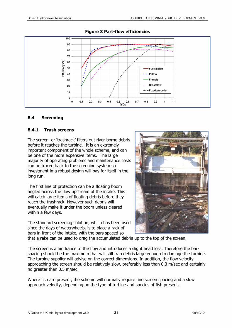
A water turbine running at a certain speed will draw a particular flow. If there is not sufficient flow in the river to meet this demand, the turbine could start to drain the river and its performance rapidly degrades. It therefore either has to shut down, or it has to change its internal geometry – a process known as regulation. Regulated turbines can move their inlet guide vanes and/or runner blades in order to increase or reduce the amount of flow they draw. The efficiency of the different turbines will inevitably reduce as they draw less flow. The typical variation is shown in Figure 3. Therefore a significant factor in the comparison of different turbine types is their relative efficiencies both at their design point and at reduced flows. For example, Pelton and Kaplan turbines retain very high efficiencies when running below design flow; whereas the efficiency of Crossflow and Francis turbines falls away more rapidly if run at below half their normal flow.

British Hydropower Association A GUIDE TO UK MINI-HYDRO DEVELOPMENT v3.0
A Guide to UK mini-hydro development v3.0 30 09/10/12
Figure 2 Principal turbine types
a. PELTON
b. TURGO
c. OPEN-FLUME FRANCIS
d. SPIRAL-CASE FRANCIS
e. PROPELLER / KAPLAN TURBINES
f. CROSSFLOW
g. ARCHIMEDES SCREW
British Hydropower Association A GUIDE TO UK MINI-HYDRO DEVELOPMENT v3.0
A Guide to UK mini-hydro development v3.0 31 09/10/12
Figure 3 Part-flow efficiencies
0
10
20
30
40
50
60
70
80
90
100
0 0.1 0.2 0.3 0.4 0.5 0.6 0.7 0.8 0.9 1 1.1Q/Qo
Eff
icie
nc
y (
%)
Full Kaplan
Pelton
Francis
Crossflow
Fixed propeller
8.4 Screening
8.4.1 Trash screens
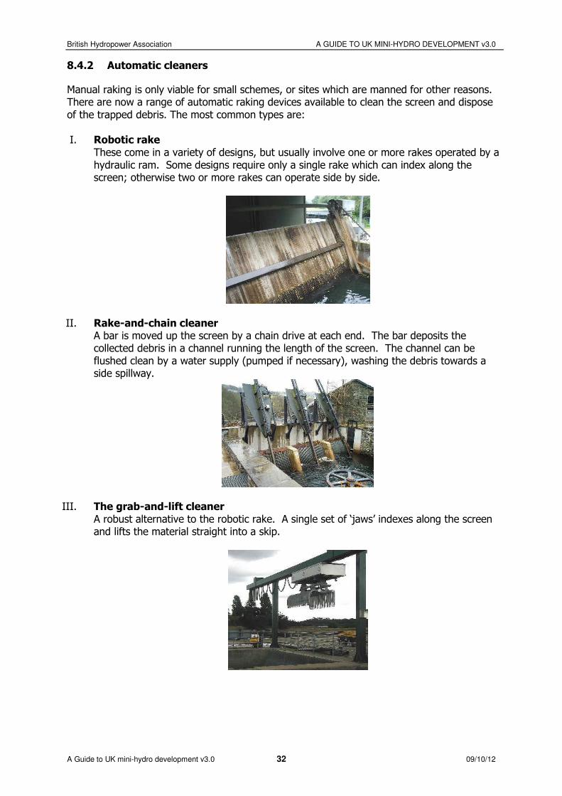
The screen, or ‘trashrack’ filters out river-borne debris before it reaches the turbine. It is an extremely important component of the whole scheme, and can be one of the more expensive items. The large majority of operating problems and maintenance costs can be traced back to the screening system so investment in a robust design will pay for itself in the long run. The first line of protection can be a floating boom angled across the flow upstream of the intake. This will catch large items of floating debris before they reach the trashrack. However such debris will eventually make it under the boom unless cleared within a few days. The standard screening solution, which has been used since the days of waterwheels, is to place a rack of bars in front of the intake, with the bars spaced so that a rake can be used to drag the accumulated debris up to the top of the screen. The screen is a hindrance to the flow and introduces a slight head loss. Therefore the bar-spacing should be the maximum that will still trap debris large enough to damage the turbine. The turbine supplier will advise on the correct dimensions. In addition, the flow velocity approaching the screen should be relatively slow, preferably less than 0.3 m/sec and certainly no greater than 0.5 m/sec. Where fish are present, the scheme will normally require fine screen spacing and a slow approach velocity, depending on the type of turbine and species of fish present.
British Hydropower Association A GUIDE TO UK MINI-HYDRO DEVELOPMENT v3.0
A Guide to UK mini-hydro development v3.0 32 09/10/12
8.4.2 Automatic cleaners
Manual raking is only viable for small schemes, or sites which are manned for other reasons. There are now a range of automatic raking devices available to clean the screen and dispose of the trapped debris. The most common types are: I. Robotic rake
These come in a variety of designs, but usually involve one or more rakes operated by a hydraulic ram. Some designs require only a single rake which can index along the screen; otherwise two or more rakes can operate side by side.
II. Rake-and-chain cleaner A bar is moved up the screen by a chain drive at each end. The bar deposits the collected debris in a channel running the length of the screen. The channel can be flushed clean by a water supply (pumped if necessary), washing the debris towards a side spillway.
III. The grab-and-lift cleaner A robust alternative to the robotic rake. A single set of ‘jaws’ indexes along the screen and lifts the material straight into a skip.
British Hydropower Association A GUIDE TO UK MINI-HYDRO DEVELOPMENT v3.0
A Guide to UK mini-hydro development v3.0 33 09/10/12
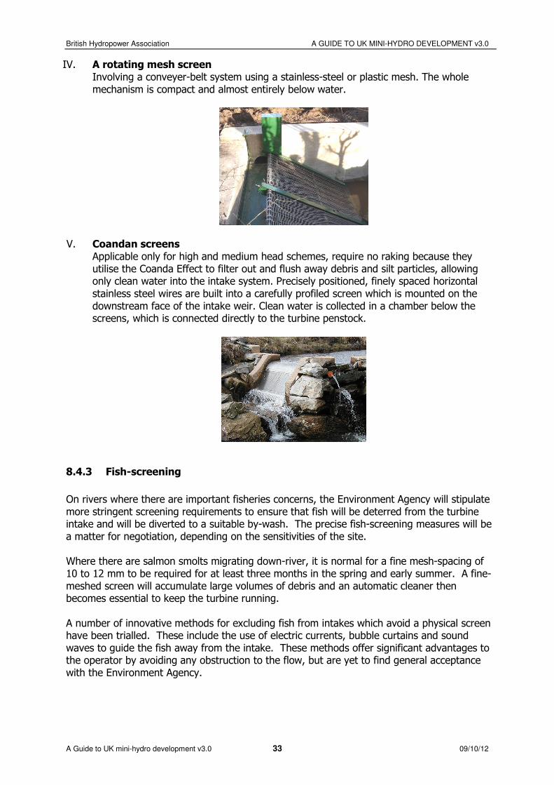
IV. A rotating mesh screen Involving a conveyer-belt system using a stainless-steel or plastic mesh. The whole mechanism is compact and almost entirely below water.
V. Coandan screens Applicable only for high and medium head schemes, require no raking because they utilise the Coanda Effect to filter out and flush away debris and silt particles, allowing only clean water into the intake system. Precisely positioned, finely spaced horizontal stainless steel wires are built into a carefully profiled screen which is mounted on the downstream face of the intake weir. Clean water is collected in a chamber below the screens, which is connected directly to the turbine penstock.
8.4.3 Fish-screening
On rivers where there are important fisheries concerns, the Environment Agency will stipulate more stringent screening requirements to ensure that fish will be deterred from the turbine intake and will be diverted to a suitable by-wash. The precise fish-screening measures will be a matter for negotiation, depending on the sensitivities of the site. Where there are salmon smolts migrating down-river, it is normal for a fine mesh-spacing of 10 to 12 mm to be required for at least three months in the spring and early summer. A fine-meshed screen will accumulate large volumes of debris and an automatic cleaner then becomes essential to keep the turbine running. A number of innovative methods for excluding fish from intakes which avoid a physical screen have been trialled. These include the use of electric currents, bubble curtains and sound waves to guide the fish away from the intake. These methods offer significant advantages to the operator by avoiding any obstruction to the flow, but are yet to find general acceptance with the Environment Agency.
British Hydropower Association A GUIDE TO UK MINI-HYDRO DEVELOPMENT v3.0
A Guide to UK mini-hydro development v3.0 34 09/10/12
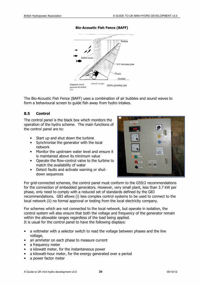
Bio-Acoustic Fish Fence (BAFF)
The Bio-Acoustic Fish Fence (BAFF) uses a combination of air bubbles and sound waves to form a behavioural screen to guide fish away from hydro intakes.
8.5 Control
The control panel is the black box which monitors the operation of the hydro scheme. The main functions of the control panel are to:
• Start up and shut down the turbine • Synchronise the generator with the local
network
• Monitor the upstream water level and ensure it is maintained above its minimum value
• Operate the flow-control valve to the turbine to match the availability of water
• Detect faults and activate warning or shut-down sequences
For grid-connected schemes, the control panel must conform to the G59/2 recommendations for the connection of embedded generators. However, very small plant, less than 3.7 kW per phase, only need to comply with a reduced set of standards defined by the G83 recommendations. G83 allows (i) less complex control systems to be used to connect to the local network (ii) no formal approval or testing from the local electricity company.
For schemes which are not connected to the local network, but operate in isolation, the control system will also ensure that both the voltage and frequency of the generator remain within the allowable ranges regardless of the load being applied. It is usual for the control panel to have the following displays: • a voltmeter with a selector switch to read the voltage between phases and the line
voltage,
• an ammeter on each phase to measure current • a frequency meter • a kilowatt meter, for the instantaneous power • a kilowatt-hour meter, for the energy generated over a period • a power factor meter

British Hydropower Association A GUIDE TO UK MINI-HYDRO DEVELOPMENT v3.0
A Guide to UK mini-hydro development v3.0 35 09/10/12
9. FURTHER INFORMATION AND ASSISTANCE
9.1 The British Hydropower Association (BHA)
The British Hydropower Association (BHA) represents the interests of all those involved in the UK
hydropower industry. It promotes the use and awareness of small hydropower, and lobbies to protect
its members' interests. Regular newsletters keep readers updated on the hydropower industry in Britain.
Membership of the Association is open to any company, organisation or individual with an interest in the use of waterpower. Members include manufacturers of all kinds of equipment used in the industry,
civil, mechanical and electrical consulting engineers, utility companies, academic institutions, developers
- large and small, individuals, charities and students - anyone who is interested in and keen to promote the use of hydropower.
9.2 Reference books
There are very few books that have focused on the issues relating specifically to small-scale
hydropower; the most useful sources of information are listed below.
Readers looking for the hydraulic theory of turbines should examine traditional hydraulics engineering textbooks; although these are usually written with large-scale projects in mind, the basic theory for a
small turbine is no different to that of a large turbine.
1. Micro-Hydro Design Manual, A.Harvey et al., IT Publications Ltd, London 1993.
A comprehensive technical guide to small-scale hydropower projects, focusing mainly on projects <500kW. It covers the whole topic from initial site survey, through to equipment selection and installation.
2. Micro-Hydro Power: a guide for development workers, P.Fraenkel, O.Paish, V.Bokalders,
A.Harvey, A.Brown, R.Edwards, IT Publications Ltd, London 1991 (reprinted 2001).
A shorter manual covering all the important topics but without going into in-depth technicalities. 3. Layman’s guidebook on how to develop a small hydro site. Published by the European
Commission, 200 Rue de la Loi, B-1049 Brussels, Belgium, 1994 (out of print but available by download from www.esha.be).
This two-volume manual describes the principal steps to be taken in the development of a small hydro site in Europe.
4. Going with the Flow: Small Scale Water Power, Billy Langley, Dan Curtis, CAT Publications
2004 5. The Micro-hydro Pelton Turbine Manual, J Thake, ITDG Publishing, 2000.
6. A UK Guide to Intake Fish Screening Legislation, Policy and Best Practice, Fawley Aquatic, Crown Copyright, Department of Trade and Industry, 1998.
9.3 Internet Links
• Web-site for the British Hydropower Association: http://www.british-hydro.org/
• WWeb-site for the European Small Hydropower Association, including download of their
Layman’s Guide to small hydro: http://www.esha.be/ • Web-site for the Micro Hydro Association, a UK forum for sharing knowledge and experience on
the development and operation of small hydro-electric schemes.
http://www.microhydroassociation.org • Internet portal for micro-hydro power news and information, with a focus on developing
countries: http://microhydropower.net
• The National River Flow Archive, containing river flow data from the UK network of over 1300
gauging stations: www.ceh.ac.uk/data/nrfa/index.html
• AAn international hydropower industry guide as compiled by The International Journal of
Hydropower and Dams – mainly oriented towards larger companies and projects: http://www.hydropower-dams.com/industryguide/
British Hydropower Association A GUIDE TO UK MINI-HYDRO DEVELOPMENT v3.0
A Guide to UK mini-hydro development v3.0 36 09/10/12
9.4 Terminology
Abstraction Licence Authorisation granted by the Environment Agency to allow the removal of water
from a source (permanently or temporarily)
Capacity factor (also called ‘Load Factor’)
The ratio of energy output per year to the maximum output if the system runs at full rated capacity all year round.
Compensation Flow The flow which must be left in the river at the point of abstraction, for ecological purposes. Also referred to as the ‘residual’, ‘reserved’, ‘prescribed’ or ‘hands-off’
flow
Fish Ladder (or Fish Pass) A structure for allowing migrant fish to travel upstream past a dam or weir, consisting of a ramp or a series of pools.
Flow Duration Curve A graph showing the percentage of time that the flow at a particular river location
equals or exceeds certain values.
Forebay An open tank for slowing down the incoming flow and settling out silt and gravel
before the flow passes into the penstock.
Gauging Station A site where the flow of a river is measured.
Gross Head The difference between the upstream and downstream water levels.
Headrace, Leat or Lade An open channel that conveys water at a shallow gradient from a watercourse to the turbine forebay tank. (Also sometimes called Goit or Contour Canal).
Impoundment Licence The authorisation granted by the Environment Agency to permit changes to
structures which impound water, such as weirs and sluices, or if new structures are to be built.
Installed Capacity The total maximum output (kW) of the generating units in a hydropower plant.
Kilowatt (kW) Unit of power, equal to 1000 watts
Kilowatt hour (kWh) Unit of electrical energy, equal to the electricity supplied by 1 kW working for 1
hour. 1 kWh = 3,600,000 Joules
Net Head The pressure head available to the turbine after friction losses through the intake,
pipeline and trash rack.
Output The amount of power (or energy depending on definition) delivered from a piece
of equipment, station or system.
Penstock A pipe (usually steel, concrete or plastic) that conveys water under pressure from
intake to turbine.
Sluice Gates A vertical shaft slide gate, which can be operated either manually or by electric motors (there are other types).
Spillway A controlled discharge of excess flow back into the river.
Tailrace The channel that takes flow away from the turbine outlet
Trashrack A protective screen that prevents large branches, tree trunks and other debris from entering and damaging the turbine. It usually consists of vertical bars
spaced between 30-100 mm apart. The screen is typically cleaned by an
automatic rake which removes the debris, either to a platform or to be flushed into the river.
Turbine A machine converting the speed and/or pressure of flowing water into rotational energy.
Weir A low dam which is designed to provide sufficient upstream depth for a water
intake while allowing flow to pass over its crest.
Acknowledgements The BHA wishes to thank Oliver Paish for drafting the text and compiling the illustrations for this guide.
Disclaimer The British Hydropower Association accepts no legal liability for the accuracy, completeness or usefulness of any information disclosed in this guide and no responsibility for any personal injury or property damage or other loss related to information herein.
© The British Hydropower Association. All rights reserved. No part of this document may be reproduced, stored in a retrieval system, or transmitted, in any form or by any means, electronic, photocopying, recording or otherwise without the prior permission of The British Hydropower Association.