Embed Size (px)
Citation preview
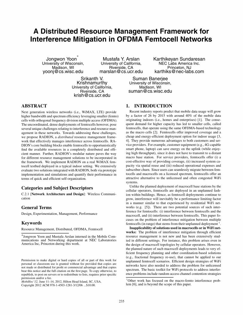
A Distributed Resource Management Framework forInterference Mitigation in OFDMA Femtocell Networks
Jongwon Yoon∗
University of Wisconsin,Madison, WI
Mustafa Y. ArslanUniversity of California,
Riverside, [email protected]
Karthikeyan SundaresanNEC Labs America Inc.
Princeton, [email protected]
Srikanth V.Krishnamurthy
University of California,Riverside, CA
Suman BanerjeeUniversity of Wisconsin,
Madison, [email protected]
ABSTRACTNext generation wireless networks (i.e., WiMAX, LTE) providehigher bandwidth and spectrum efficiency leveraging smaller (femto)cells with orthogonal frequency division multiple access (OFDMA).The uncoordinated, dense deployments of femtocells however, poseseveral unique challenges relating to interference and resource man-agement in these networks. Towards addressing these challenges,we propose RADION, a distributed resource management frame-work that effectively manages interference across femtocells. RA-DION’s core building blocks enable femtocells to opportunisticallyfind the available resources in a completely distributed and effi-cient manner. Further, RADION’s modular nature paves the wayfor different resource management solutions to be incorporated inthe framework. We implement RADION on a real WiMAX fem-tocell testbed deployed in a typical indoor setting. We extensivelyevaluate two solutions integrated with RADION, both via prototypeimplementation and simulations and quantify their performance interms of quick and efficient self-organization.
Categories and Subject DescriptorsC.2.1 [Network Architecture and Design]: Wireless Communi-cation
General TermsDesign, Experimentation, Management, Performance
KeywordsResource Management, Distributed, OFDMA, Femtocell
∗Jongwon Yoon and Mustafa Arslan interned in the Mobile Com-munications and Networking department at NEC LaboratoriesAmerica Inc, Princeton during this work.
Permission to make digital or hard copies of all or part of this work forpersonal or classroom use is granted without fee provided that copies arenot made or distributed for profit or commercial advantage and that copiesbear this notice and the full citation on the first page. To copy otherwise, torepublish, to post on servers or to redistribute to lists, requires prior specificpermission and/or a fee.MobiHoc’12, June 11–14, 2012, Hilton Head Island, SC, USA.Copyright 2012 ACM 978-1-4503-1281-3/12/06 ...$10.00.
1. INTRODUCTIONRecent industry reports predict that mobile data usage will grow
by a factor of 26 by 2015 with around 40% of the mobile dataoriginating indoors (i.e., homes and enterprises) [1]. The conse-quent demand for higher capacity has led to smaller cells, calledfemtocells, that operate using the same OFDMA-based technologyas the macro cells [2]. Femtocells offer improved coverage and acheap and energy-efficient deployment option for indoor usage [3,4]. They provide numerous advantages to both customers and ser-vice providers. For example, customer equipment (e.g., 4G-capablesmart phone, laptop) can save energy on the uplink (while enjoy-ing high throughput), since it does not have to transmit to a distantmacro base station. For service providers, femtocells offer (i) acost-effective way of providing coverage, (ii) increased system ca-pacity via spatial reuse and (iii) reduced operational expenses andsubscriber churn. Since users can seamlessly migrate between fem-tocells and macrocells on a licensed spectrum, femtocells offer anattractive alternative to the unlicensed and often congested WiFisystems.
Unlike the planned deployment of macrocell base stations by thecellular operators, femtocells are deployed in an unplanned fash-ion within buildings. Hence, as femtocell deployments continue togrow, interference will inevitably be a performance limiting factorin a manner similar to that experienced by residential WiFi net-works (e.g. [5]). There are two potential sources of such inter-ference for femtocells: (i) interference between femtocells and themacrocell, and (ii) interference between femtocells. This paper fo-cuses on the problem of interference mitigation between multiplefemtocells (in range) that stems from their unplanned deployment 1.
Inapplicability of solutions used in macrocells or in WiFi net-works: The problem of interference mitigation through efficientresource management is not new and has been extensively stud-ied in different settings. For instance, this problem arises even inthe design of macrocell topologies by cellular operators. However,the planned nature of such macrocell deployments leads to very ef-ficient frequency planning and other coordination-based solutions(e.g., fractional frequency re-use), that cannot be applied to ourunplanned femtocell scenarios. Efficient design strategies of WiFinetworks have also needed to address the problem for unlicensedspectrum. The basic toolkit for WiFi protocols to address interfer-ence problems include random access channel contention strategies
1Other work has focused on the macro-femto interference prob-lem [6], and is beyond the scope of this paper.
235
that de-synchronize competing transmitters in time through meth-ods of carrier sensing and back-off. Unfortunately, femtocells can-not leverage such strategies since their MAC-PHY protocols are re-quired to follow the same synchronous channel access methods astheir macrocell counterparts. More specifically, standard OFDMAfemtocells do not employ carrier sensing based deferral. Hence,they cannot sense the spectrum occupied by other cells to tunethemselves onto orthogonal frequencies to resolve interference. Fi-nally, unlike in WiFi, a single OFDMA frame carries data for multi-ple clients, and our resource management strategies are constrainedby these requirements.
RADION – Distributed femtocell resource management: Wepropose RADION, a framework for distributed management of time-frequency resources in OFDMA-based femtocell networks. Thisframework is designed for the scenario where nearby femtocellscannot explicitly coordinate or interact with each other, and henceis suitable for unplanned residential deployments. Our specific so-lution requires each femto base station (BS) to intelligently probeavailability of resources and use them in an opportunistic and dis-tributed manner. We contrast this design to a centralized resourcemanagement solution, called FERMI, that was recently proposedfor femtocells [7]. More specifically, FERMI focused on femtocelldeployments in enterprise settings, where multiple femtocells wereassumed to cooperate towards a network-wide objective. In par-ticular, the design in FERMI required the centralized collection ofthe global network view, constructed through explicit informationexchange between the various femtocells. Such cooperation is notrealistic for residential settings. Hence the solution in RADION isstylized such that each residential femto BS will try to optimize forits own local objective, without explicitly exchanging informationwith neighboring femtocell BSs.
Several challenges arise in designing a distributed resource man-agement framework for OFDMA femtocells: (i) OFDMA sched-ules multiple clients in the same frame. The clients experiencedifferent levels of interference and hence, a resource managementframework has to account for the characteristics of each client.Specifically, clients with strong interference need to operate onorthogonal resources (i.e., frequency isolation), while clients withweak interference can operate on all frequency resources (i.e., reuse).For the efficient use of resources in OFDMA frames, we need tofirst differentiate the clients. (ii) Given that multiple clients shareframe resources in OFDMA networks, the next challenge is “howto accommodate multiple clients of various classes in the sameframe?". The frame structure has to be carefully managed for var-ious clients considering their interference levels and demands. Inparticular, each cell needs to determine how much resources canbe reused without causing interference to the neighboring cells andhow much frequency resources need to be isolated to mitigate theinterference from other cells. The frame structure can impact thenetwork wide resource reuse as well, where multiple contentiondomains are involved. (iii) The resources allocated to one fem-tocell directly impact the resources for the interfering cells. Weneed to determine the time and frequency resources of operation forthe clients in each cell while accounting for the resources used byneighboring cells. Resource allocation for each femtocell should beadaptive to the network changes, but without explicit coordinationdue to lack of any central component in the system.
In RADION, we address the above challenges through the spe-cific design of the following three building blocks:
• Client Categorization: Active probing is used by the BS tocategorize clients into two classes, those that require resourceisolation to mitigate the interference and those that can reusethe spectrum, based on their interference levels. Client cat-
DL Burst1
DL Burst2 ULBurst2
ULBurst1 FCH
Downlink Uplink
Fr
eque
ncy
(Sub
-cha
nnel
s)
Prea
mbl
e
DL-
MA
P
UL-
MA
P
Tile
Time (Symbols)
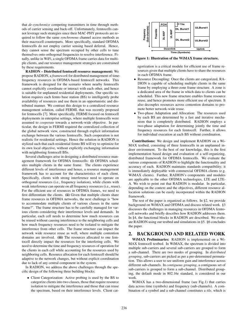
Figure 1: Illustration of the WiMAX frame structure.
egorization is a critical module for efficient use of frame re-sources given that multiple clients have to share the resourcesin each OFDMA frame.• Resource Decoupling: Once the clients are categorized, RA-
DION is capable of scheduling multiple clients in the sameframe by employing a three-zone frame structure. A zone isa dedicated area of the frame in which data to clients can bescheduled. This new frame structure enables frame resourcereuse, and hence promotes more efficient use of spectrum. Italso decouples resources across contention domains to pro-mote better network-wide reuse.• Two-phase Adaptation and Allocation: The resources used
by each BS are determined by a fast and iterative mecha-nism that is completely distributed. RADION employs atwo-phase adaptation for determining jointly the time andfrequency resources for each femtocell. Further, it allowsfor individual execution at each BS without coordination.
Contributions: We design and implement RADION on a Wi-MAX testbed, consisting of three femtocells in an unplanned in-door environment. To the best of our knowledge, this is the firstimplementation based design and evaluation of a self-organizing,distributed framework for OFDMA femtocells. We evaluate thevarious components of RADION to highlight the functionality andaccuracy of each. RADION maintains standards compatibility; itis immediately deployable with commercial OFDMA clients (e.g.WiMAX clients). Further, RADION’s components and modulesare applicable to the other OFDMA technologies, LTE and LTE-A. We wish to point out that RADION is modular. In particular,depending on the context and the objectives, different resource al-location solutions can be easily incorporated within the RADIONframework.
The rest of the paper is organized as follows. In §2, we providebackground on WiMAX and OFDMA and discuss related work. §3discusses the challenges in managing resources in OFDMA femto-cell networks and briefly describes how RADION addresses them.In §4, the functional blocks in RADION are described. We evalu-ate RADION using our testbed and simulations in §5. §6 concludesthe paper.
2. BACKGROUND AND RELATED WORKWiMAX Preliminaries: RADION is implemented on a Wi-
MAX femtocell testbed. In WiMAX, the spectrum is divided intomultiple sub-carriers and several sub-carriers are grouped to forma sub-channel. There are two modes of grouping. In distributedgrouping, sub-carriers are picked as per a pre-determined permuta-tion. This allows a user to see uniform gain and interference acrossdifferent sub-channels. In contiguous grouping, a contiguous set ofsub-carriers is grouped to form a sub-channel. Distributed group-ing, the default mode in 802.16e standard, is considered in ourwork.
WiMAX has a two-dimensional frame (see Fig.1) that carriesdata across time (symbols) and frequency (sub-channels). A com-bination of a symbol and a sub-channel constitutes a tile, which is
236
the basic unit of resource allocation. Data to multiple mobile sta-tions (MSs) are scheduled as rectangular bursts of tiles in a frameand frames are sent out periodically (every 5ms). Mainly, framesconsist of two parts; downlink (from BS to the MS) and uplink(from the MS to the BS). Downlink frames contain the pream-ble, control and data bursts. While the preamble allows a MS toassociate with the BS, the control consists of FCH (frame con-trol header) and MAP. The DL-MAP indicates where each burstis placed in the frame, which MS it is sent to, and what modulationand coding scheme (MCS) should be used to decode it.
Related Work: While OFDMA standards (e.g., WiMAX, LTE)have been drafted recently, related research has existed for sometime [8]. Efforts that focus on the macro-femtocells interference [9]and the interference to cell-edge users in OFDMA macrocells exist.The localized (cell edge) interference and planned cell layouts haveaided various interference management solutions [10]. These alsoinclude fractional frequency partitioning (FFR) approaches [11],where the spectrum is partitioned into pre-determined static sets.Unlike macrocells, femtocells are deployed in an unplanned man-ner without coordinated operations and are hence, vulnerable tointerference. This necessitates novel interference mitigation solu-tions. There have been recent studies [9, 12] in this direction butare restricted to theory with several simplifying assumptions thatrestrict their scope and deployment.
Recently in [7], FERMI, a centralized resource management so-lution for enterprise femtocell deployments was proposed. How-ever, RADION is a completely distributed solution targeting un-planned deployment settings (such as residences), where coopera-tion among femtocells (implicitly assumed in [7]) is not realistic.The concepts of zoning and client categorization were also used inFERMI; however, access to global knowledge at a central controllermade it easy to design these functions. RADION allows each fem-tocell to intelligently determine its zones in a conservative manner.Unlike in FERMI, to account for inaccuracies in distributed zonedetermination, a transition zone is introduced (details later). Thisin turn makes the client categorization in RADION also differentfrom that in FERMI; clients that access the medium in the transi-tion zone have to be chosen with care. Due to lack of coordination,accurate client categorization is all the more critical for efficientuse of resources.
Diverging from the cellular context, recent efforts show the ben-efits of OFDMA in WiFi by building systems that enable dynamicspectrum fragmentation [13] and adaptive channel width [14]. InWiFi, APs use one among multiple 20 MHz channels and severalconventional distributed channel selection algorithms [5] can beused to configure APs on different channels to avoid interference.However, in femtocells, the entire spectral chunk (say 20MHz) isavailable to all the cells. They need to operate on mutually or-thogonal subsets of frame resources (sub-channels and time sym-bols) to avoid interference. Thus, resource allocation has to adaptto network dynamics (such as traffic, load etc.). Here, we seekto distributively and quickly determine the resources for each cell.Further, resource allocation constitutes just one component in ourbroader goal of designing a framework for distributed resource man-agement for femtocells.
3. RESOURCE MANAGEMENT CHALLE-NGES
The problem of resource management is for each femtocell todistributively determine the frame resources (tiles) that it can use toschedule its clients. Since the resource allocation decisions of onecell impact multiple other cells, efficient mechanisms are needed toquickly converge to a network-wide resource allocation. We first
15
ReuseIsolationTransitionZone
15
R
R:I:T:
RI
I
21 Time
Frequency
0 27
RIT
21
BS1 BS2 BS2 with Trans. zone
Interference from BS121
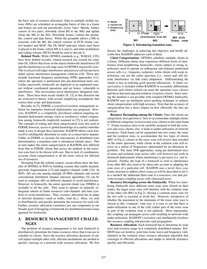
Figure 2: Introducing transition zone.
discuss the challenges in achieving this objective and briefly de-scribe how RADION addresses each of them.
Client Categorization: OFDMA schedules multiple clients ina frame. Different clients may experience different levels of inter-ference from neighboring femtocells; clients subject to strong in-terference need to operate on orthogonal sub-channels partitionedacross cells (i.e., frequency isolation), while clients with weak in-terference can use the entire spectrum (i.e., reuse) and still tol-erate interference via link (rate) adaptation. Differentiating theclients is key in realizing good spectral efficiencies. A client cat-egorization is included within RADION to accurately differentiatebetween such clients (which can reuse the spectrum reuse clients)and those that need spectral isolation (isolation clients). Since sens-ing the medium is not possible with standard OFDMA femtocells,RADION uses an intelligent active probing technique to achieveclient categorization with high accuracy. Note that the accuracy ofcategorization has a direct impact on how efficiently the tiles areutilized.
Resource Decoupling among the Clients: Once the clients arecategorized, next question is “how to accommodate multiple clientsof different categories (isolation and reuse clients) in the same frame?". Frame resources have to be carefully assigned to both the isola-tion and reuse clients; else, it leads to under-utilization of networkresources. Each frame can be segmented into two zones, the reuseand the isolation zone, to accommodate the two types of clients(BS1 in Fig.2) ;clients in the reuse zone will receive data encodedon the entire spectrum, while clients in the isolation zone will re-ceive on a subset of frequencies (determined by an allocation al-gorithm). The static FFR approaches, using pre-determined sizesof reuse and isolation zone across cells, will however not work infemtocell deployments where interference is pervasive (i.e., not lo-calized). Further, the load of a femtocell as well as interferencefrom other BSs also need to be taken into account in adapting thezone sizes of a particular cell. RADION uses a novel three-zoneframe structure to address these issues as will be described in §4.2;in a nutshell the additional third zone is a transition zone that pre-vents resource coupling across cells (discussed next).
Resource Decoupling across the Femtocells: When two inter-fering femtocells have different reuse zone sizes (based on theirloads), the larger reuse zone will interfere with the isolation zoneof the other cell (BS2 in Fig.2). Having a common reuse zone forthe two cells is essential to avoid this. However, irrespective ofwhether the maximum or the minimum of the reuse zone sizes ischosen as this “common" zone size, it is easy to see that there isunder-utilization in one of the cells (either part of the reuse zoneor part of the isolation zone is not utilized). More importantly,this coupling can propagate across cells resulting in network-wideunder-utilization. RADION’s transition zone intelligently localizesthis resource coupling and prevents such propagation.
Resource Allocation: Each femtocell has to determine its zonesizes and resource usage in a completely distributed manner. RA-DION uses an iterative, joint time (zone sizes) and frequency (sub-channels in the isolation zone) resource allocation algorithm thatconverges to efficient allocations and adapts to network dynamicsquickly and efficiently.
237
RESOURCEISOLATION
F
req
uen
cy
FR
EE
RE
US
ETime
OC
CU
PIE
D
(a) Measurement zones
1
2
1 2 3 4 5 6 7 8 9 10111213141516171819
Clie
nt c
ateg
ory
Location
Ground truthInitial step
Refined step
(b) Categorization results
BS1
10
15 10 5
Demanded Reuse Zone Size (symbols)
15 5 10
R R RI
I
IT
15
T
BS2 BS3
(c) Illustration of three-zone structure
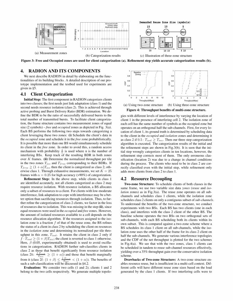
Figure 3: Free and Occupied zones are used for client categorization (a). Refinement step yields accurate categorization results (b).
4. RADION AND ITS COMPONENTSWe next describe RADION in detail by elaborating on the func-
tionalities of its building blocks. A detailed description of our pro-totype implementation and the testbed used for experiments aregiven in §5.
4.1 Client CategorizationInitial Step: The first component in RADION categorizes clients
into two classes; the first needs just link adaptation (class 1) and thesecond needs resource isolation (class 2). This is achieved throughactive probing and Burst Delivery Ratio (BDR) estimation. We de-fine the BDR to be the ratio of successfully delivered bursts to thetotal number of transmitted bursts. To facilitate client categoriza-tion, the frame structure contains two measurement zones of equalsize (2 symbols) – free and occupied zones as depicted in Fig. 3(a).Each BS performs the following two steps towards categorizing aclient leveraging these two zones: (i) Schedule the client’s data inthe occupied zone and schedule it in the free zone probabilistically.It is possible that more than one BS would simultaneously scheduleits client in the free zone. In order to avoid this, a random accessmechanism with probability 1
nis used where n is the number of
interfering BSs. Keep track of the resulting BDR in both zonesover K frames. (ii) Determine the normalized throughput per tilein the two zones Tocc and Tfree corresponding to their BDRs. IfTfree ≥ (1 + α)Tocc then the client is categorized as class 2; oth-erwise class 1. Through exhaustive measurements, we set K = 25frames with α = 0.25 for high accuracy (>90%) of categorization.
Refinement Step: In the above step, while clients in class 1are identified accurately, not all clients categorized as class 2 mayrequire resource isolation. With resource isolation, a BS allocatesonly a subset of resources to a client. For clients with low-moderateinterference, link adaptation to cope with interference may be a bet-ter option than sacrificing resources through isolation. Thus, to fur-ther refine the categorization of class 2 clients, we factor in the lossof resources due to isolation. This was missing in the step (ii), sinceequal resources were used in the occupied and free zones. However,the amount of isolated resources available to a cell depends on theresource allocation algorithm. If the resources assigned to the iso-lation zone is a fraction f of that of the reuse zone, the BS refinesthe status of a client in class 2 by scheduling the client on resourcesin the isolation zone and determining its normalized per tile thro-ughput in this zone, Tisol. It retains the client in class 2 only iff · Tisol ≥ (1 + β)Tocc; the client is reverted to class 1 otherwise.Here, β (0.05, experimentally obtained) is used to avoid oscilla-tions in categorization. RADION further sub-classifies clients inclass 2 as those that benefit significantly from resource isolation(class 2h: f ·Tisol
Tocc≥ (1 + α)) and those that benefit marginally
from it (class 2l: (1 + β) ≤ f ·TisolTocc
< (1 + α)). The benefits ofsuch a sub-classification will be discussed in §4.2.
Evaluation: We consider two cells (1 and 2); clients 1 and 2belong to the two cells respectively. We generate multiple topolo-
0
0.2
0.4
0.6
0.8
1
0 2 4 6 8 10 12
CD
F
Throughput(Mbps)
BaselineZoning
(a) Using two-zone structure
0
0.2
0.4
0.6
0.8
1
4 5 6 7 8 9
CD
F
Throughput(Mbps)
2Z2Z-CR
3Z3Z-Opt
(b) Using three-zone structure
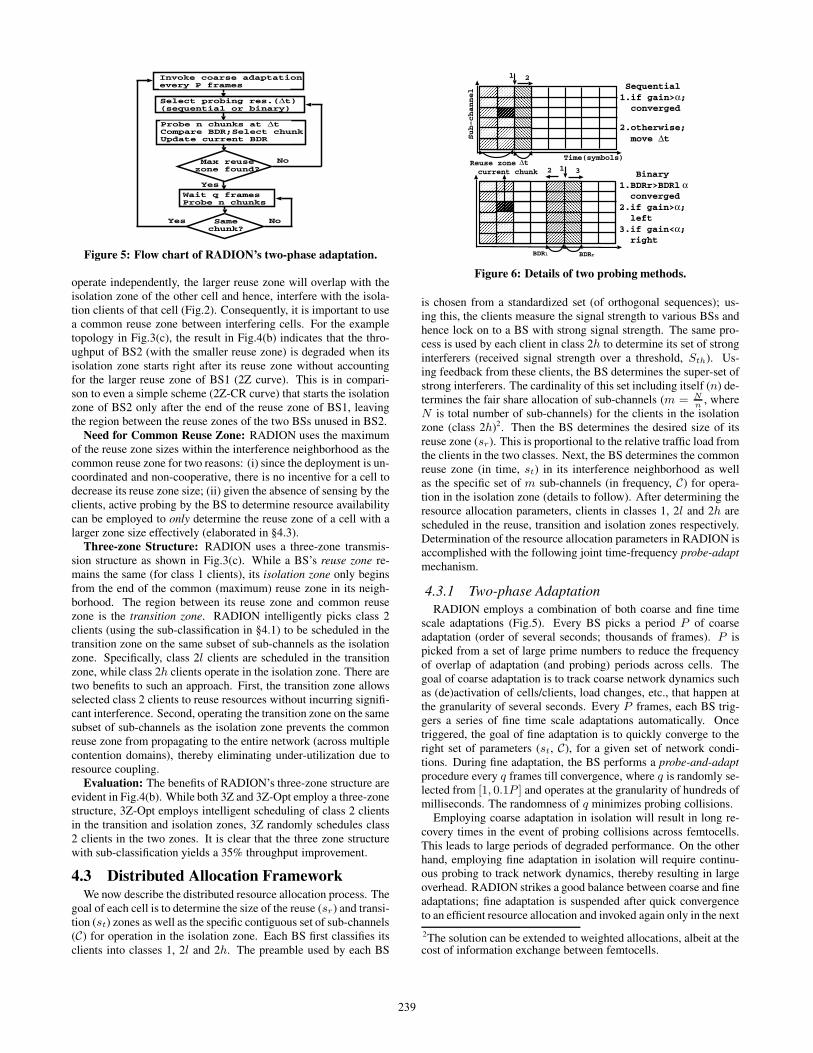
Figure 4: Throughput benefits of multi-zone structure.
gies with different levels of interference by varying the location ofclient 1 in the presence of interfering cell 2. The isolation zone ofeach cell has the same number of symbols as the occupied zone butoperates on an orthogonal half the sub-channels. First, for every lo-cation of client 1, its ground truth is determined by scheduling datato the client in the occupied and isolation zones and determining itas class 2 if 0.5 · Tisol ≥ Tocc. Then our three step categorizationalgorithm is executed. The categorization results of the initial andthe refinement steps are shown in Fig.3(b). It is seen that the ini-tial step wrongly categorizes clients in ten locations, however, therefinement step corrects most of them. The only erroneous clas-sification (location 2) was due to a change in channel conditionsduring the process. The clients who need to be in class 2 are cor-rectly classified even with the initial step, while refinement onlyadds more clients from class 2 to class 1.
4.2 Resource DecouplingTwo-zone Structure: To schedule clients of both classes in the
same frame, we use two variable size data zones (reuse and iso-lation zones) as in Fig.3(a). The reuse zone operates on all sub-channels and schedules class 1 clients, while the isolation zoneschedules class 2 clients on only a contiguous subset of sub-channels.To understand the benefits of the two-zone structure, we conductexperiments with two BSs. Each BS has two clients (one in eachclass), and interferes with the class 2 client of the other BS. Thebaseline scheme operates the two BSs on two orthogonal sets ofsub-channels, with each BS scheduling both its clients within itsown subset. This is compared against a two-zone scheme where aBS schedules its class 1 client on all sub-channels, while the iso-lation zone uses the other half of the frame for its class 2 client onhalf the sub-channels. We generate various interference topologiesand the CDF of the net throughput is plotted for the two schemesin Fig.4(a). We see that with the two zones, class 1 clients canbe scheduled in tandem to reuse sub-channel resources effectively,yielding over a 35% throughput gain over the conservative isolationscheme.
Drawbacks of Two-zone Structure: A two-zone structure en-ables resource reuse, but is insufficient in a multi-cell context. Dif-ferent cells will have different reuse zone sizes based on the loadgenerated by the class 1 clients. If two interfering cells were to
238
Invoke coarse adaptationevery P frames
Max reuse zone found?
Select probing res.(Δt)(sequential or binary)
No
Yes
Same chunk?
NoYes
Wait q framesProbe n chunks
Probe n chunks at ΔtCompare BDR;Select chunkUpdate current BDR
Figure 5: Flow chart of RADION’s two-phase adaptation.
operate independently, the larger reuse zone will overlap with theisolation zone of the other cell and hence, interfere with the isola-tion clients of that cell (Fig.2). Consequently, it is important to usea common reuse zone between interfering cells. For the exampletopology in Fig.3(c), the result in Fig.4(b) indicates that the thro-ughput of BS2 (with the smaller reuse zone) is degraded when itsisolation zone starts right after its reuse zone without accountingfor the larger reuse zone of BS1 (2Z curve). This is in compari-son to even a simple scheme (2Z-CR curve) that starts the isolationzone of BS2 only after the end of the reuse zone of BS1, leavingthe region between the reuse zones of the two BSs unused in BS2.
Need for Common Reuse Zone: RADION uses the maximumof the reuse zone sizes within the interference neighborhood as thecommon reuse zone for two reasons: (i) since the deployment is un-coordinated and non-cooperative, there is no incentive for a cell todecrease its reuse zone size; (ii) given the absence of sensing by theclients, active probing by the BS to determine resource availabilitycan be employed to only determine the reuse zone of a cell with alarger zone size effectively (elaborated in §4.3).
Three-zone Structure: RADION uses a three-zone transmis-sion structure as shown in Fig.3(c). While a BS’s reuse zone re-mains the same (for class 1 clients), its isolation zone only beginsfrom the end of the common (maximum) reuse zone in its neigh-borhood. The region between its reuse zone and common reusezone is the transition zone. RADION intelligently picks class 2clients (using the sub-classification in §4.1) to be scheduled in thetransition zone on the same subset of sub-channels as the isolationzone. Specifically, class 2l clients are scheduled in the transitionzone, while class 2h clients operate in the isolation zone. There aretwo benefits to such an approach. First, the transition zone allowsselected class 2 clients to reuse resources without incurring signifi-cant interference. Second, operating the transition zone on the samesubset of sub-channels as the isolation zone prevents the commonreuse zone from propagating to the entire network (across multiplecontention domains), thereby eliminating under-utilization due toresource coupling.
Evaluation: The benefits of RADION’s three-zone structure areevident in Fig.4(b). While both 3Z and 3Z-Opt employ a three-zonestructure, 3Z-Opt employs intelligent scheduling of class 2 clientsin the transition and isolation zones, 3Z randomly schedules class2 clients in the two zones. It is clear that the three zone structurewith sub-classification yields a 35% throughput improvement.
4.3 Distributed Allocation FrameworkWe now describe the distributed resource allocation process. The
goal of each cell is to determine the size of the reuse (sr) and transi-tion (st) zones as well as the specific contiguous set of sub-channels(C) for operation in the isolation zone. Each BS first classifies itsclients into classes 1, 2l and 2h. The preamble used by each BS
Time(symbols)
2
Sub-channel
Sequential 1.if gain>α; converged
2.otherwise; move Δt
Δt
1
31 Binary1.BDRr>BDRl α converged2.if gain>α; left3.if gain<α; right
2
BDRrBDRl
Reuse zonecurrent chunk
Figure 6: Details of two probing methods.
is chosen from a standardized set (of orthogonal sequences); us-ing this, the clients measure the signal strength to various BSs andhence lock on to a BS with strong signal strength. The same pro-cess is used by each client in class 2h to determine its set of stronginterferers (received signal strength over a threshold, Sth). Us-ing feedback from these clients, the BS determines the super-set ofstrong interferers. The cardinality of this set including itself (n) de-termines the fair share allocation of sub-channels (m = N
n, where
N is total number of sub-channels) for the clients in the isolationzone (class 2h)2. Then the BS determines the desired size of itsreuse zone (sr). This is proportional to the relative traffic load fromthe clients in the two classes. Next, the BS determines the commonreuse zone (in time, st) in its interference neighborhood as wellas the specific set of m sub-channels (in frequency, C) for opera-tion in the isolation zone (details to follow). After determining theresource allocation parameters, clients in classes 1, 2l and 2h arescheduled in the reuse, transition and isolation zones respectively.Determination of the resource allocation parameters in RADION isaccomplished with the following joint time-frequency probe-adaptmechanism.
4.3.1 Two-phase AdaptationRADION employs a combination of both coarse and fine time
scale adaptations (Fig.5). Every BS picks a period P of coarseadaptation (order of several seconds; thousands of frames). P ispicked from a set of large prime numbers to reduce the frequencyof overlap of adaptation (and probing) periods across cells. Thegoal of coarse adaptation is to track coarse network dynamics suchas (de)activation of cells/clients, load changes, etc., that happen atthe granularity of several seconds. Every P frames, each BS trig-gers a series of fine time scale adaptations automatically. Oncetriggered, the goal of fine adaptation is to quickly converge to theright set of parameters (st, C), for a given set of network condi-tions. During fine adaptation, the BS performs a probe-and-adaptprocedure every q frames till convergence, where q is randomly se-lected from [1, 0.1P ] and operates at the granularity of hundreds ofmilliseconds. The randomness of q minimizes probing collisions.
Employing coarse adaptation in isolation will result in long re-covery times in the event of probing collisions across femtocells.This leads to large periods of degraded performance. On the otherhand, employing fine adaptation in isolation will require continu-ous probing to track network dynamics, thereby resulting in largeoverhead. RADION strikes a good balance between coarse and fineadaptations; fine adaptation is suspended after quick convergenceto an efficient resource allocation and invoked again only in the next
2The solution can be extended to weighted allocations, albeit at thecost of information exchange between femtocells.
239
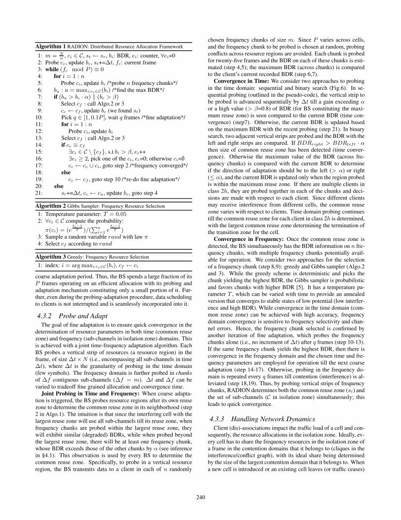
Algorithm 1 RADION: Distributed Resource Allocation Framework
1: m = Nn
, ci ∈ C, st ← sr, bi: BDR, ei: counter, ∀ei=02: Probe cc, update bc, st+=Δt, fc: current frame3: while (fc mod P ) ≡ 04: for i = 1 : n5: Probe ci, update bi /*probe n frequency chunks*/6: bu : u = maxi:ci∈C(bi) /*find the max BDR*/7: if (bu > bc · α) ‖ (bc > β)8: Select cf : call Algo.2 or 39: cc ← cf , update bc (we found st)
10: Pick q ∈ [1, 0.1P ], wait q frames /*fine adaptation*/11: for i = 1 : n12: Probe ci, update bi
13: Select cf : call Algo.2 or 314: if cc ≡ cf
15: ∃ci ∈ C \ {cf}, s.t bi > β, ei++16: ∃ei ≥ 2, pick one of the ci, ei=0; otherwise ci=∅17: cc ← cc ∪ ci, goto step 2 /*frequency converged*/18: else19: cc ← cf , goto step 10 /*re-do fine adaptation*/20: else21: st+=Δt, cc ← cu, update bc, goto step 4
Algorithm 2 Gibbs Sampler: Frequency Resource Selection
1: Temperature parameter: T = 0.052: ∀ci ∈ C compute the probability:
π(ci) = (ebi−1
T )/(Pn
i=1 ebi−1
T )3: Sample a random variable rand with law π4: Select cf according to rand
Algorithm 3 Greedy: Frequency Resource Selection
1: index: i = arg maxi:ci∈C(bi), cf ← ci
coarse adaptation period. Thus, the BS spends a large fraction of itsP frames operating on an efficient allocation with its probing andadaptation mechanism constituting only a small portion of it. Fur-ther, even during the probing-adaptation procedure, data schedulingto clients is not interrupted and is seamlessly incorporated into it.
4.3.2 Probe and AdaptThe goal of fine adaptation is to ensure quick convergence in the
determination of resource parameters in both time (common reusezone) and frequency (sub-channels in isolation zone) domains. Thisis achieved with a joint time-frequency adaptation algorithm. EachBS probes a vertical strip of resources (a resource region) in theframe, of size Δt×N (i.e., encompassing all sub-channels in timeΔt), where Δt is the granularity of probing in the time domain(few symbols). The frequency domain is further probed in chunksof Δf contiguous sub-channels (Δf = m). Δt and Δf can bevaried to tradeoff fine grained allocation and convergence time.
Joint Probing in Time and Frequency: When coarse adapta-tion is triggered, the BS probes resource regions after its own reusezone to determine the common reuse zone in its neighborhood (step2 in Algo.1). The intuition is that since the interfering cell with thelargest reuse zone will use all sub-channels till its reuse zone, whenfrequency chunks are probed within the largest reuse zone, theywill exhibit similar (degraded) BDRs, while when probed beyondthe largest reuse zone, there will be at least one frequency chunk,whose BDR exceeds those of the other chunks by α (see inferencein §4.1). This observation is used by every BS to determine thecommon reuse zone. Specifically, to probe in a vertical resourceregion, the BS transmits data to a client in each of n randomly
chosen frequency chunks of size m. Since P varies across cells,and the frequency chunk to be probed is chosen at random, probingconflicts across resource regions are avoided. Each chunk is probedfor twenty-five frames and the BDR on each of these chunks is esti-mated (step 4,5); the maximum BDR (across chunks) is comparedto the client’s current recorded BDR (step 6,7).
Convergence in Time: We consider two approaches to probingin the time domain: sequential and binary search (Fig.6). In se-quential probing (outlined in the pseudo-code), the vertical strip tobe probed is advanced sequentially by Δt till a gain exceeding αor a high value (> β=0.8) of BDR (for BS constituting the maxi-mum reuse zone) is seen compared to the current BDR (time con-vergence) (step7). Otherwise, the current BDR is updated basedon the maximum BDR with the recent probing (step 21). In binarysearch, two adjacent vertical strips are probed and the BDR with theleft and right strips are compared. If BDRright > BDRleft · αthen size of common reuse zone has been detected (time conver-gence). Otherwise the maximum value of the BDR (across fre-quency chunks) is compared with the current BDR to determineif the direction of adaptation should be to the left (> α) or right(≤ α), and the current BDR is updated only when the region probedis within the maximum reuse zone. If there are multiple clients inclass 2h, they are probed together in each of the chunks and deci-sions are made with respect to each client. Since different clientsmay receive interference from different cells, the common reusezone varies with respect to clients. Time domain probing continuestill the common reuse zone for each client in class 2h is determined,with the largest common reuse zone determining the termination ofthe transition zone for the cell.
Convergence in Frequency: Once the common reuse zone isdetected, the BS simultaneously has the BDR information on n fre-quency chunks, with multiple frequency chunks potentially avail-able for operation. We consider two approaches for the selectionof a frequency chunk (step 8,9): greedy and Gibbs sampler (Algo.2and 3). While the greedy scheme is deterministic and picks thechunk yielding the highest BDR, the Gibbs sampler is probabilisticand favors chunks with higher BDR [5]. It has a temperature pa-rameter T , which can be varied with time to provide an annealedversion that converges to stable states of low potential (low interfer-ence and high BDR). While convergence in the time domain (com-mon reuse zone) can be achieved with high accuracy, frequencydomain convergence is sensitive to frequency selectivity and chan-nel errors. Hence, the frequency chunk selected is confirmed byanother iteration of fine adaptation, which probes the frequencychunks alone (i.e., no increment of Δt) after q frames (step 10-13).If the same frequency chunk yields the highest BDR, then there isconvergence in the frequency domain and the chosen time and fre-quency parameters are employed for operation till the next coarseadaptation (step 14-17). Otherwise, probing in the frequency do-main is repeated every q frames till contention (interference) is al-leviated (step 18,19). Thus, by probing vertical strips of frequencychunks, RADION determines both the common reuse zone (st) andthe set of sub-channels (C in isolation zone) simultaneously; thisleads to quick convergence.
4.3.3 Handling Network DynamicsClient (dis)-associations impact the traffic load of a cell and con-
sequently, the resource allocations in the isolation zone. Ideally, ev-ery cell has to share the frequency resources in the isolation zone ofa frame in the contention domains that it belongs to (cliques in theinterference/conflict graph), with its ideal share being determinedby the size of the largest contention domain that it belongs to. Whena new cell is introduced or an existing cell leaves (or traffic ceases)
240
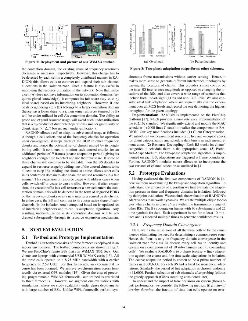
Figure 7: Deployment and picture of our WiMAX testbed.
the contention domain, the existing share of frequency resourcesdecreases or increases, respectively. However, this change has tobe detected by each cell in a completely distributed manner in RA-DION; this allows cells to contract and expand their sub-channelallocations in the isolation zone. Such a feature is also useful inimproving the resource utilization in the network. Note that, sincea cell (A) does not have information on its contention domains (re-quires global knowledge), it computes its fair share (say x, x ≤ideal share) based on its interfering neighbors. However, if oneof its neighboring cells (B) belongs to a larger contention domain(hence has a lower share < x), then some resources (unused by B)will be under-utilized in cell A’s contention domain. The ability toprobe and expand resource usage will avoid such under-utilizationthat is a by-product of distributed operations (smaller granularity ofchunk sizes (< Δf ) lowers such under-utilization).
RADION allows a cell to adapt its sub-channel usage as follows.Although a cell selects one of the frequency chunks for operationupon convergence, it keeps track of the BDR in other frequencychunks and hence the potential set of chunks unused by its neigh-boring cells. It continues to monitor such unused chunks for anadditional period of P frames (coarse adaptation period), giving itsneighbors enough time to detect and use their fair share. If some ofthese chunks still continue to be available, then the BS decides toexpand its resource usage by adding one of the unused chunks to itsallocation (step 16). Adding one chunk at a time, allows other cellsin its contention domain to also share the unused resources in a fairmanner. This expansion of resource usage will address cases whencells switch off or cease to carry traffic. However, if after expan-sion, the ceased traffic in a cell restarts or a new cell enters the con-tention domain, this will be detected in the form of degraded BDRson the frequency chunks or as a new interferer sensed by its clients.In either case, the BS will contract to its conservative share of sub-channels (in the isolation zone) computed based on its updated setof interfering neighbors and re-run its adaptation algorithm. Anyresulting under-utilization in its contention domains will be ad-dressed subsequently through its resource expansion mechanism.
5. SYSTEM EVALUATION
5.1 Testbed and Prototype ImplementationTestbed: Our testbed consists of three femtocells deployed in an
indoor environment. The testbed components are shown in Fig.7.We use PicoChip’s femto BSs that run WiMAX (802.16e). Ourclients are laptops with commercial USB WiMAX cards [15]. Allthe three cells operate on a 8.75 MHz bandwidth with a carrierfrequency of 2.59 GHz. For this frequency, an experimental li-cense has been obtained. We achieve synchronization across fem-tocells via external GPS modules [16]. Given the cost of procur-ing programmable WiMAX femtocells, our testbed is restrictedto three femtocells. However, we augment our evaluations withsimulations, where we study scalability under dense deploymentswith large number of BSs. Unlike WiFi, femtocells perform syn-
0
4
8
12
16
20
Coarse Fine Two Phase 0
3
6
9
12
Ove
rlap D
ura
tion (
%)
Ove
rlap D
ura
tion
per
Fals
e D
eci
sion (
sec)
RatioDuration
(a) Overhead
0
3
6
9
12
15
Coarse Fine Two Phase 0
2
4
6
8
Fals
e D
eci
sions
(%)
Pro
bin
g C
olli
sions
(%)
False DecisionsProbing Collisions
(b) False decision
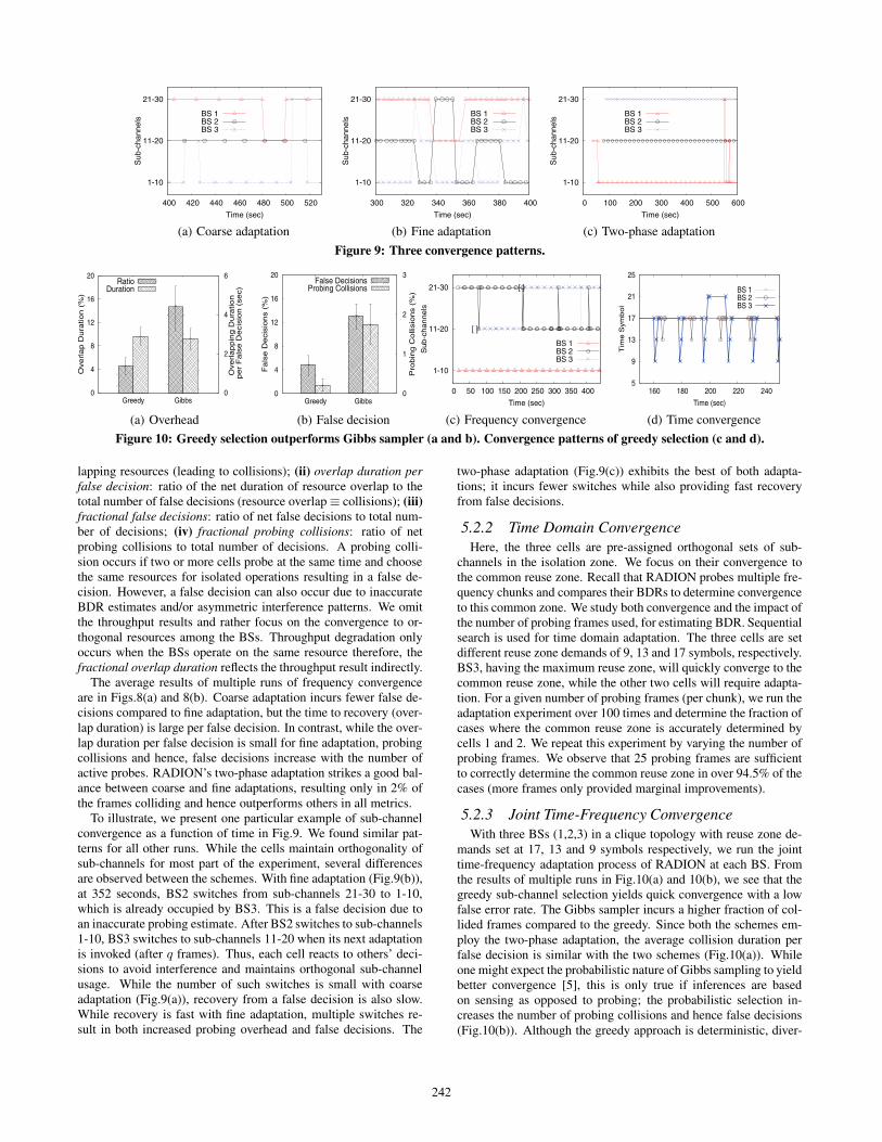
Figure 8: Two-phase adaptation outperforms other schemes.
chronous frame transmissions without carrier sensing. Hence, itmakes more sense to generate different interference topologies byvarying the locations of clients. This provides a finer control onthe inter-BS interference magnitude as opposed to changing the lo-cations of the BSs, and also covers a wide range of scenarios thatinclude both line-of-sight (LOS) and non-LOS links. We also con-sider ideal link adaptation where we sequentially run the experi-ment over all MCS levels and record the one delivering the highestthroughput for the given topology.
Implementation: RADION is implemented on the PicoChipplatform [17], which provides a base reference implementation ofthe 802.16e standard. We significantly extend and modify the MACscheduler (≈2000 lines C code) to realize the components in RA-DION. Our key modifications include: (1) Client Categorization:We introduce two measurement zones (i.e., free and occupied zones)for client categorization and schedule data bursts in each measure-ment zone. (2) Resource Decoupling: Each BS tracks its clients’categories to schedule them in the appropriate zone. (3) Probe-and-Adapt Module: The two-phase adaptation algorithm is imple-mented on each BS; adaptations are triggered at frame boundaries.Further, RADION’s modular nature allows us to incorporate thetwo variants of channel selection as outlined in §4.
5.2 Prototype EvaluationsHaving evaluated the first two components of RADION in §4,
here we focus on evaluating the two-phase adaptation algorithm. Tounderstand the efficiency of algorithm we first evaluate the adapta-tion process in time and frequency domains in isolation, followedby their joint evaluation. We conclude the evaluation of RADION’sadaptiveness to network dynamics. We create multiple clique topolo-gies where clients in class 2h are within the transmission range ofother BSs. The BSs operate on frames with 30 sub-channels and 22time symbols for data. Each experiment is run for at least 10 min-utes and is repeated multiple times to generate confidence results.
5.2.1 Frequency Domain ConvergenceHere, we fix the reuse zone of all the three cells to be the same,
thereby eliminating the need for determining a common reuse zone.Hence, the focus is only on frequency domain convergence in theisolation zone for class 2h clients; every cell has to identify andoperate on a contiguous set of 10 sub-channels each (3 contendingcells). We evaluate RADION’s two-phase (coarse + fine) adapta-tion against the coarse and fine time scale adaptations in isolation.The coarse adaptation period is chosen to be a prime number offrames in [1000,6000] for each BS and is fixed for subsequent adap-tations. Similarly, the period of fine adaptation is chosen randomlyin [1,600]. Further, selection of sub-channels after probing followsthe greedy approach (Gibbs sampling considered later).
To understand the impact of false decisions on system (through-put) performance, we consider the following metrics: (i) fractionaloverlap duration: the fraction of time that cells operate on over-
241
1-10
11-20
21-30
400 420 440 460 480 500 520
Sub
-cha
nnel
s
Time (sec)
BS 1BS 2BS 3
(a) Coarse adaptation
1-10
11-20
21-30
300 320 340 360 380 400
Sub
-cha
nnel
s
Time (sec)
BS 1BS 2BS 3
(b) Fine adaptation
1-10
11-20
21-30
0 100 200 300 400 500 600
Sub
-cha
nnel
s
Time (sec)
BS 1BS 2BS 3
(c) Two-phase adaptation
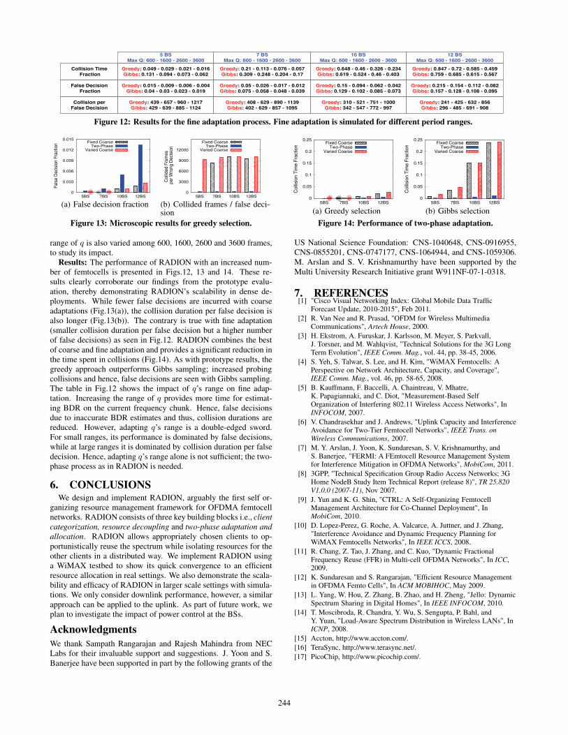
Figure 9: Three convergence patterns.
0
4
8
12
16
20
Greedy Gibbs 0
2
4
6
Ove
rla
p D
ura
tion
(%
)
Ove
rla
pp
ing
Du
ratio
n
pe
r F
als
e D
eci
sio
n (
sec)
RatioDuration
(a) Overhead
0
4
8
12
16
20
Greedy Gibbs 0
1
2
3F
als
e D
eci
sio
ns
(%)
Pro
bin
g C
olli
sio
ns
(%)
False DecisionsProbing Collisions
(b) False decision
1-10
11-20
21-30
0 50 100 150 200 250 300 350 400
Su
b-c
ha
nn
els
Time (sec)
[ ]
[ ]
BS 1BS 2BS 3
(c) Frequency convergence
5
9
13
17
21
25
160 180 200 220 240
Tim
e S
ym
bo
l
Time (sec)
BS 1BS 2BS 3
(d) Time convergence
Figure 10: Greedy selection outperforms Gibbs sampler (a and b). Convergence patterns of greedy selection (c and d).
lapping resources (leading to collisions); (ii) overlap duration perfalse decision: ratio of the net duration of resource overlap to thetotal number of false decisions (resource overlap≡ collisions); (iii)fractional false decisions: ratio of net false decisions to total num-ber of decisions; (iv) fractional probing collisions: ratio of netprobing collisions to total number of decisions. A probing colli-sion occurs if two or more cells probe at the same time and choosethe same resources for isolated operations resulting in a false de-cision. However, a false decision can also occur due to inaccurateBDR estimates and/or asymmetric interference patterns. We omitthe throughput results and rather focus on the convergence to or-thogonal resources among the BSs. Throughput degradation onlyoccurs when the BSs operate on the same resource therefore, thefractional overlap duration reflects the throughput result indirectly.
The average results of multiple runs of frequency convergenceare in Figs.8(a) and 8(b). Coarse adaptation incurs fewer false de-cisions compared to fine adaptation, but the time to recovery (over-lap duration) is large per false decision. In contrast, while the over-lap duration per false decision is small for fine adaptation, probingcollisions and hence, false decisions increase with the number ofactive probes. RADION’s two-phase adaptation strikes a good bal-ance between coarse and fine adaptations, resulting only in 2% ofthe frames colliding and hence outperforms others in all metrics.
To illustrate, we present one particular example of sub-channelconvergence as a function of time in Fig.9. We found similar pat-terns for all other runs. While the cells maintain orthogonality ofsub-channels for most part of the experiment, several differencesare observed between the schemes. With fine adaptation (Fig.9(b)),at 352 seconds, BS2 switches from sub-channels 21-30 to 1-10,which is already occupied by BS3. This is a false decision due toan inaccurate probing estimate. After BS2 switches to sub-channels1-10, BS3 switches to sub-channels 11-20 when its next adaptationis invoked (after q frames). Thus, each cell reacts to others’ deci-sions to avoid interference and maintains orthogonal sub-channelusage. While the number of such switches is small with coarseadaptation (Fig.9(a)), recovery from a false decision is also slow.While recovery is fast with fine adaptation, multiple switches re-sult in both increased probing overhead and false decisions. The
two-phase adaptation (Fig.9(c)) exhibits the best of both adapta-tions; it incurs fewer switches while also providing fast recoveryfrom false decisions.
5.2.2 Time Domain ConvergenceHere, the three cells are pre-assigned orthogonal sets of sub-
channels in the isolation zone. We focus on their convergence tothe common reuse zone. Recall that RADION probes multiple fre-quency chunks and compares their BDRs to determine convergenceto this common zone. We study both convergence and the impact ofthe number of probing frames used, for estimating BDR. Sequentialsearch is used for time domain adaptation. The three cells are setdifferent reuse zone demands of 9, 13 and 17 symbols, respectively.BS3, having the maximum reuse zone, will quickly converge to thecommon reuse zone, while the other two cells will require adapta-tion. For a given number of probing frames (per chunk), we run theadaptation experiment over 100 times and determine the fraction ofcases where the common reuse zone is accurately determined bycells 1 and 2. We repeat this experiment by varying the number ofprobing frames. We observe that 25 probing frames are sufficientto correctly determine the common reuse zone in over 94.5% of thecases (more frames only provided marginal improvements).
5.2.3 Joint Time-Frequency ConvergenceWith three BSs (1,2,3) in a clique topology with reuse zone de-
mands set at 17, 13 and 9 symbols respectively, we run the jointtime-frequency adaptation process of RADION at each BS. Fromthe results of multiple runs in Fig.10(a) and 10(b), we see that thegreedy sub-channel selection yields quick convergence with a lowfalse error rate. The Gibbs sampler incurs a higher fraction of col-lided frames compared to the greedy. Since both the schemes em-ploy the two-phase adaptation, the average collision duration perfalse decision is similar with the two schemes (Fig.10(a)). Whileone might expect the probabilistic nature of Gibbs sampling to yieldbetter convergence [5], this is only true if inferences are basedon sensing as opposed to probing; the probabilistic selection in-creases the number of probing collisions and hence false decisions(Fig.10(b)). Although the greedy approach is deterministic, diver-
242

1-5
6-10
11-15
16-20
21-25
26-30
0 100 200 300 400 500
Sub
-cha
nnel
s
Time (sec)
BS 1
BS 2
BS 3
(a) Clique topology
1-5
6-10
11-15
16-20
21-25
26-30
0 100 200 300 400 500 600
Sub
-cha
nnel
s
Time (sec)
BS 1
BS 2
BS 3
(b) Three-links chain topology
Figure 11: Convergence of RADION with network dynamics.
sity in sub-channel gain across BSs (and their clients) implicitlyresults in cells picking different frequency resources for their op-eration. Since both the schemes employ the same time-domainadaptation procedure, their convergence error in the time domainremains similar and less than 5%.
The time-frequency convergence patterns for the greedy schemeare shown in Figs.10(c) and 10(d). Here we present one exam-ple of the multiple runs but we confirm very similar pattens for allruns. The frequency adaptations are directly indicated. False con-vergences in the time domain are indicated by brackets to capturethe duration for which the cell operates with a wrong common reusezone. We see that the number of probing collisions and the result-ing quick switch in sub-channel resources to maintain orthogonal-ity in the frequency domain. We omit the pattern of Gibbs samplingfor the sake of brevity; however, we highlight that it shows manymore frequent switches as the results (Fig.10(a) and 10(b)) show.The time convergence pattern for the greedy approach is expandedin Fig.10(d). We see that BS3 computes the common reuse zonefalsely as 21 symbols (instead of 17) at 200 secs; this is correctedin the next coarse adaptation period. Till the reuse zone is cor-rected, BS3’s false decision does not cause interference to BS1’sand BS2’s class 2h clients since it continues to use its isolated re-sources in its transition zone. However, BS3’s class 2h clients nowincur unfairness as their operational resources are reduced by foursymbols. Since the number of false decisions is very small, we letthese correct themselves in the next coarse adaptation period.
In summary, we find that the joint time-frequency adaptation pro-cess in RADION yields quick and accurate convergence at eachfemtocell to the common reuse zone as well as to provide orthogo-nal sub-channels in the isolation zone.
5.2.4 Network Dynamics: Single Contention DomainWe now evaluate RADION’s ability to adapt to network changes.
First, we consider a single contention domain where all BSs causeinterference to each other. In the clique topology of three cells, RA-DION’s adaptation algorithm allows each BS to detect its fair shareand converge to orthogonal sets of 10 sub-channels in the isolation
zone. The frequency convergence pattern is shown in Fig.11(a),where frequency resources are probed at the granularity of five sub-channel chunks. RADION’s resource expansion mechanism allowseach BS to expand its frequency resources in the isolation zone ifit probes empty resources for more than a coarse adaptation pe-riod. When BS3 is switched off at about 210 seconds (indicatedby the arrow), its sub-channels 11-20 become free. BS1 probesthe availability of chunks 11-15 and 16-20 but decides to expandits resources only to 1-15, to allow fair access to other cells in thecontention domain. However, since the chunk 16-20 remains avail-able in the next adaptation period as well, BS1 continues to expandits resources to 1-20. BS2 fails to grab the chunk 16-20 due toan inaccurate BDR estimate. Thus, while RADION paves the wayfor a distributed fair sharing of unused resources, distributed oper-ations without information sharing prevents it from controlling theutilization-fairness tradeoff in the best way possible.
5.2.5 Network Dynamics: Multiple Contention Do-mains
Here we evaluate the adaptiveness in a multiple contention do-main by creating chain topology BS3-BS1-BS2; the ideal fair sharesof all BSs are 15 sub-channels each. However, since BS1 doesnot have global information, it computes its fair share to be 10sub-channels (based on two interfering neighbors) without realiz-ing that its neighbors belong to different contention domains. BS2and BS3 compute their fair shares as 15 sub-channels each. RA-DION’s resource expansion can help BS1 salvage under-utilizedresources. The convergence is shown in Fig.11(b). Initially, whileBS2 and BS3 converge to operate on sub-channels from 16-30,BS1 converges to sub-channels 1-10. RADION’s resource expan-sion/contraction feature is enabled after 200 seconds. At this point,BS1 probes the available chunk from 11-15 and expands its allo-cation to 1-15; this remains stable till 370 secs. At 370 secs, BS2expands its allocation to 11-30 due to an inaccurate probing, whichis immediately rectified in the next adaptation. This again happensat around 510 secs. However, this time, before BS2 rectifies its de-cision, BS1 responds to interference by contracting its allocationback to its initial fair share of 1-10. This in turn prompts BS3 toprobe and expand its allocation to 11-30 (similar to BS2).
The above experiment demonstrates that when a new BS joinsthe contention domain, it is detected by other cells in the domain;these BSs update (contract) their fair share and run the adaptationprocess to determine their isolated resources. Stated otherwise, itsuccinctly captures both the expansion and contraction features in-corporated into RADION to track network changes. It also indi-cates the transition between a fair allocation and one with high uti-lization. However, to finely control such transitions, informationexchange across multiple cells is required, which may not be feasi-ble in residential environments. RADION’s best-effort utilization-fairness tradeoffs are particularly suited for such environments.
5.3 Evaluation through SimulationsSimulation Set-up: To understand RADION’s effectiveness in
dense deployments, we resort to simulations. We simulate a singlecontention domain and increase the number of BSs to stress testRADION’s convergence in the frequency domain. We consider twoversions of coarse adaptation: (a) a BS picks a fixed prime numberof frames P from [8000, 16000], and (b) P is varied (randomly)across adaptation periods. A larger range is chosen for P to avoidexcessive probing collisions. For fine adaptation, q is chosen from[n× s, 600], where n is the number of BSs and s is the number ofprobes sent on each chunk (set to 10 frames). The variable range isbased on the observation that smaller ranges are unfair when a largenumber of BSs simultaneously probe and adapt. The maximum
243
Greedy: 310 - 521 - 751 - 1000Gibbs: 342 - 547 - 772 - 997
Greedy: 439 - 657 - 960 - 1217Gibbs: 429 - 639 - 885 - 1124
Greedy: 408 - 629 - 890 - 1139Gibbs: 402 - 629 - 857 - 1095
Collision perFalse Decision
Greedy: 241 - 425 - 632 - 856Gibbs: 296 - 485 - 691 - 908
Greedy: 0.215 - 0.154 - 0.112 - 0.082Gibbs: 0.157 - 0.128 - 0.108 - 0.095
Greedy: 0.847 - 0.72 - 0.585 - 0.459Gibbs: 0.759 - 0.685 - 0.615 - 0.567
12 BSMax Q: 600 - 1600 - 2600 - 3600
Greedy: 0.648 - 0.46 - 0.326 - 0.234Gibbs: 0.619 - 0.524 - 0.46 - 0.403
10 BSMax Q: 600 - 1600 - 2600 - 3600
Greedy: 0.15 - 0.094 - 0.062 - 0.042Gibbs: 0.129 - 0.102 - 0.085 - 0.073
Greedy: 0.21 - 0.113 - 0.076 - 0.057Gibbs: 0.309 - 0.248 - 0.204 - 0.17
Greedy: 0.049 - 0.029 - 0.021 - 0.016Gibbs: 0.131 - 0.094 - 0.073 - 0.062
False Decision Fraction
5 BSMax Q: 600 - 1600 - 2600 - 3600
7 BSMax Q: 600 - 1600 - 2600 - 3600
Collision Time Fraction
Greedy: 0.015 - 0.009 - 0.006 - 0.004Gibbs: 0.04 - 0.03 - 0.023 - 0.019
Greedy: 0.05 - 0.026 - 0.017 - 0.012Gibbs: 0.075 - 0.058 - 0.048 - 0.039
Figure 12: Results for the fine adaptation process. Fine adaptation is simulated for different period ranges.
0
0.003
0.006
0.009
0.012
0.015
5BS 7BS 10BS 12BS
Fals
e D
ecis
ion
Frac
tion Fixed Coarse
Two-PhaseVaried Coarse
(a) False decision fraction
0
3000
6000
9000
12000
5BS 7BS 10BS 12BS
Col
lided
Fra
mes
p
er W
rong
Dec
isio
n
Fixed CoarseTwo-Phase
Varied Coarse
(b) Collided frames / false deci-sion
Figure 13: Microscopic results for greedy selection.
range of q is also varied among 600, 1600, 2600 and 3600 frames,to study its impact.
Results: The performance of RADION with an increased num-ber of femtocells is presented in Figs.12, 13 and 14. These re-sults clearly corroborate our findings from the prototype evalu-ation, thereby demonstrating RADION’s scalability in dense de-ployments. While fewer false decisions are incurred with coarseadaptations (Fig.13(a)), the collision duration per false decision isalso longer (Fig.13(b)). The contrary is true with fine adaptation(smaller collision duration per false decision but a higher numberof false decisions) as seen in Fig.12. RADION combines the bestof coarse and fine adaptation and provides a significant reduction inthe time spent in collisions (Fig.14). As with prototype results, thegreedy approach outperforms Gibbs sampling; increased probingcollisions and hence, false decisions are seen with Gibbs sampling.The table in Fig.12 shows the impact of q’s range on fine adap-tation. Increasing the range of q provides more time for estimat-ing BDR on the current frequency chunk. Hence, false decisionsdue to inaccurate BDR estimates and thus, collision durations arereduced. However, adapting q’s range is a double-edged sword.For small ranges, its performance is dominated by false decisions,while at large ranges it is dominated by collision duration per falsedecision. Hence, adapting q’s range alone is not sufficient; the two-phase process as in RADION is needed.
6. CONCLUSIONSWe design and implement RADION, arguably the first self or-
ganizing resource management framework for OFDMA femtocellnetworks. RADION consists of three key building blocks i.e., clientcategorization, resource decoupling and two-phase adaptation andallocation. RADION allows appropriately chosen clients to op-portunistically reuse the spectrum while isolating resources for theother clients in a distributed way. We implement RADION usinga WiMAX testbed to show its quick convergence to an efficientresource allocation in real settings. We also demonstrate the scala-bility and efficacy of RADION in larger scale settings with simula-tions. We only consider downlink performance, however, a similarapproach can be applied to the uplink. As part of future work, weplan to investigate the impact of power control at the BSs.
AcknowledgmentsWe thank Sampath Rangarajan and Rajesh Mahindra from NECLabs for their invaluable support and suggestions. J. Yoon and S.Banerjee have been supported in part by the following grants of the
0
0.05
0.1
0.15
0.2
0.25
5BS 7BS 10BS 12BS
Col
lisio
n T
ime
Fra
ctio
n
Fixed CoarseTwo-Phase
Varied Coarse
(a) Greedy selection
0
0.05
0.1
0.15
0.2
0.25
5BS 7BS 10BS 12BS
Col
lisio
n T
ime
Fra
ctio
n
Fixed CoarseTwo-Phase
Varied Coarse
(b) Gibbs selection
Figure 14: Performance of two-phase adaptation.
US National Science Foundation: CNS-1040648, CNS-0916955,CNS-0855201, CNS-0747177, CNS-1064944, and CNS-1059306.M. Arslan and S. V. Krishnamurthy have been supported by theMulti University Research Initiative grant W911NF-07-1-0318.
7. REFERENCES[1] "Cisco Visual Networking Index: Global Mobile Data Traffic
Forecast Update, 2010-2015", Feb 2011.[2] R. Van Nee and R. Prasad, "OFDM for Wireless Multimedia
Communications", Artech House, 2000.[3] H. Ekstrom, A. Furuskar, J. Karlsson, M. Meyer, S. Parkvall,
J. Torsner, and M. Wahlqvist, "Technical Solutions for the 3G LongTerm Evolution", IEEE Comm. Mag., vol. 44, pp. 38-45, 2006.
[4] S. Yeh, S. Talwar, S. Lee, and H. Kim, "WiMAX Femtocells: APerspective on Network Architecture, Capacity, and Coverage",IEEE Comm. Mag., vol. 46, pp. 58-65, 2008.
[5] B. Kauffmann, F. Baccelli, A. Chaintreau, V. Mhatre,K. Papagiannaki, and C. Diot, "Measurement-Based SelfOrganization of Interfering 802.11 Wireless Access Networks", InINFOCOM, 2007.
[6] V. Chandrasekhar and J. Andrews, "Uplink Capacity and InterferenceAvoidance for Two-Tier Femtocell Networks", IEEE Trans. onWireless Communications, 2007.
[7] M. Y. Arslan, J. Yoon, K. Sundaresan, S. V. Krishnamurthy, andS. Banerjee, "FERMI: A FEmtocell Resource Management Systemfor Interference Mitigation in OFDMA Networks", MobiCom, 2011.
[8] 3GPP, "Technical Specification Group Radio Access Networks; 3GHome NodeB Study Item Technical Report (release 8)", TR 25.820V1.0.0 (2007-11), Nov 2007.
[9] J. Yun and K. G. Shin, "CTRL: A Self-Organizing FemtocellManagement Architecture for Co-Channel Deployment", InMobiCom, 2010.
[10] D. Lopez-Perez, G. Roche, A. Valcarce, A. Juttner, and J. Zhang,"Interference Avoidance and Dynamic Frequency Planning forWiMAX Femtocells Networks", In IEEE ICCS, 2008.
[11] R. Chang, Z. Tao, J. Zhang, and C. Kuo, "Dynamic FractionalFrequency Reuse (FFR) in Multi-cell OFDMA Networks", In ICC,2009.
[12] K. Sundaresan and S. Rangarajan, "Efficient Resource Managementin OFDMA Femto Cells", In ACM MOBIHOC, May 2009.
[13] L. Yang, W. Hou, Z. Zhang, B. Zhao, and H. Zheng, "Jello: DynamicSpectrum Sharing in Digital Homes", In IEEE INFOCOM, 2010.
[14] T. Moscibroda, R. Chandra, Y. Wu, S. Sengupta, P. Bahl, andY. Yuan, "Load-Aware Spectrum Distribution in Wireless LANs", InICNP, 2008.
[15] Accton, http://www.accton.com/.[16] TeraSync, http://www.terasync.net/.[17] PicoChip, http://www.picochip.com/.
244