Embed Size (px)
Citation preview

A Design Study in Steel Castings Crossbleed Valve for the F-5 Jet Fighter
Design Study OutlineIntroductionDesign for Performance Steel Alloy SelectionDesign for Production Investment Casting Controlled Solidification Gating DesignFinal Design and Pouring Heat Treatment and MachiningQuality AssuranceLessons Learned and Summary
Northrop F-5E Tiger -- Fighter Jet
Key Words = metal casting, stainless steel, investment casting, 17-4PH, directional solidification
Start the Design Study!
Acknowledgment --The metalcasting design studies are a joint effort of the
Steel Founders' Society of America and the American Foundry Society.Project funding was provided by the American Metalcasting Consortium Project, which
is sponsored by the Defense Logistics Agency, Attn: DLSC-T, Ft. Belvoir, VA, 22060-6221
Return to SFSAHome Page
Copyright 2007 by the Steel Founders' Society of America. All rights reserved. Address comments to: [email protected] Modified:December, 2007 by STG
A Design Study in Steel - Crossbleed Valve for the F-5
Crossbleed Valve -- ApplicationThe F-5 fighter planes were first designed and built in the 1960s by
Northrop in the United States. It is a supersonic fighter suitable for a wide range of ground-support and aerial intercept missions.
● In a fighter configuration, the F-5 plane is 47 feet long and has a 25 foot wingspan.
● The fighter is powered by two General Electric J85-GE-13 turbojets.
● The F-5 has a maximum take-off weight of 24,644# and a maximum speed of 925 mph (1.4 Mach) with a service ceiling of 50,500 feet.
● The F-5 was produced in several different versions ( fighter, recon, two-seat trainers) and is still widely used by foreign air forces.
F-5 Fighter in Flight
More than 2,000 F-5 aircraft have been purchased by allied nations. The Defense Logistics Agency (DLA) procures a significant number of spare parts for the F-5 as part of its Foreign
Military Sales support mission.
Back Next 2
Returnto SFSAHome Page
Copyright 2007 by the Steel Founders' Society of America.All rights reserved. Address comments to: [email protected] Modified:December, 2007 by STG
Page 1

A Design Study in Steel - Crossbleed Valve for the F-5
Crossbleed Valve -- ApplicationThe F-5 plane is powered by two General Electric (GE)
J85 augmented turbojet engines.
GE J85 Turbojet
● The basic engine design is about 18 inches in diameter and 45 inches long.
● In the front of the engine there is an eight-stage axial-flow compressor powered by two turbine stages.
● At full throttle at sea level without afterburner, the engine consumes approximately 400 gallons of fuel per hour.
● At cruise altitude and power, the engine consumes approximately 100 gallons per hour.
The J85 offers the highest thrust-to-weight ratio (rated at 2720 lb.s.t., 4080 lb.s.t. with afterburning) of any production engine in its class. The engine has more than 75 million flight
hours experience on military and commercial aircraft.
Back Next 3
Returnto SFSAHome Page
Copyright 2007 by the Steel Founders' Society of America.All rights reserved. Address comments to: [email protected] Modified:December, 2007 by STG
Page 1
A Design Study in Steel - Crossbleed Valve for the F-5
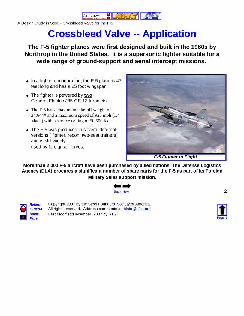
Crossbleed Valve -- FunctionBleed air is hot, compressed air taken from the engine compressor, which
is used as an important source of energy for the aircraft.
The bleed air contains usable energy in the form of its high pressure and high temperature. Bleed air can be used within an aircraft in many different ways -
● starting a second engine and/or an auxiliary power unit/electrical generator.
● powering pneumatic actuators and servosystems.
● deicing the engine and wings.
● maintaining cabin pressurization and environmental conditions.
Back Next 4
Returnto SFSAHome Page
Copyright 2007 by the Steel Founders' Society of America.All rights reserved. Address comments to: [email protected] Modified:December, 2007 by STG
Page 1
A Design Study in Steel - Crossbleed Valve for the F-5
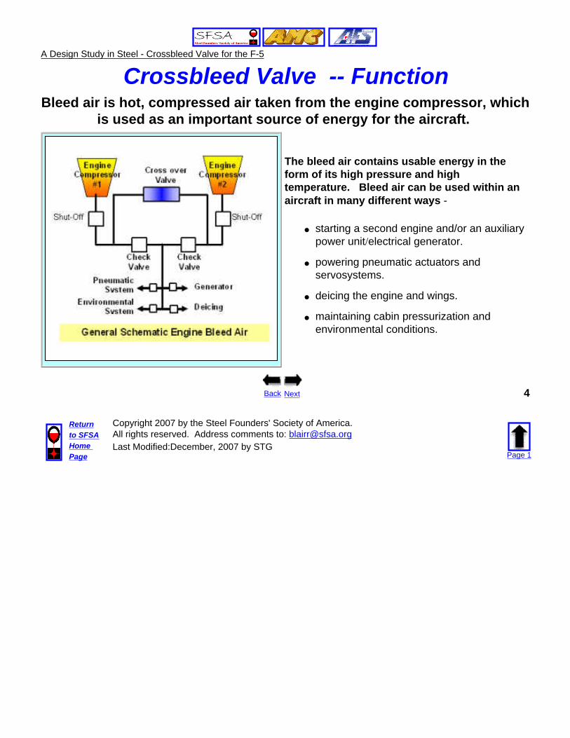
Crossbleed Valve -- FunctionThe crossbleed valve in the F-5 engine is the primary control valve for
directing bleed air between the two engines.
● The valve has to regulate the flow of hot (>500 F) compressed (~100 psi) air.
● The valve system operates across the full range of engine compartment temperatures in a high vibration, high noise environment.
● The valve main cylinder contains a butterfly valve flap that is controlled by an off-axis electric actuator.
Back Next 5
Returnto SFSAHome Page
Copyright 2007 by the Steel Founders' Society of America.All rights reserved. Address comments to: [email protected] Modified:December, 2007 by STG
Page 1

A Design Study in Steel - Crossbleed Valve for the F-5
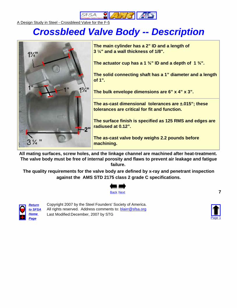
Crossbleed Valve -- Description The crossbleed valve body is a complex near-net shape body, consisting of a flanged thin wall (1/8”) main cylinder attached to a flanged actuator cup by a cylindrical connecting shaft angled off the main cylinder.
● Bleed air flow is through the main cylinder, controlled by the butterfly valve.● The valve actuator is inserted in the cup. ● The two ends of the main cylinder and the top of the cup are flanged for connections.● The connecting shaft is drilled out for the linkage between the actuator and the butterfly valve.
The production requirement for the valve body is 100 pieces per annum.
Back Next 6
Returnto SFSAHome Page
Copyright 2007 by the Steel Founders' Society of America.All rights reserved. Address comments to: [email protected] Modified:December, 2007 by STG
Page 1
A Design Study in Steel - Crossbleed Valve for the F-5
Crossbleed Valve Body -- Description
The main cylinder has a 2” ID and a length of 3 ¼" and a wall thickness of 1/8".
The actuator cup has a 1 ¾” ID and a depth of 1 ¾".
The solid connecting shaft has a 1” diameter and a length of 1".
The bulk envelope dimensions are 6” x 4” x 3”.
The as-cast dimensional tolerances are ±.015”; these tolerances are critical for fit and function.
The surface finish is specified as 125 RMS and edges are radiused at 0.12”.
The as-cast valve body weighs 2.2 pounds before machining.
All mating surfaces, screw holes, and the linkage channel are machined after heat-treatment. The valve body must be free of internal porosity and flaws to prevent air leakage and fatigue
failure. The quality requirements for the valve body are defined by x-ray and penetrant inspection
against the AMS STD 2175 class 2 grade C specifications.
Back Next 7
Returnto SFSAHome Page
Copyright 2007 by the Steel Founders' Society of America.All rights reserved. Address comments to: [email protected] Modified:December, 2007 by STG
Page 1
A Design Study in Steel - Crossbleed Valve for the F-5
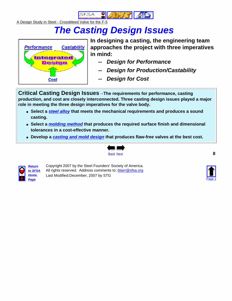
The Casting Design Issues In designing a casting, the engineering team approaches the project with three imperatives in mind:
-- Design for Performance-- Design for Production/Castability-- Design for Cost
Critical Casting Design Issues --The requirements for performance, casting production, and cost are closely interconnected. Three casting design issues played a major role in meeting the three design imperatives for the valve body.
● Select a steel alloy that meets the mechanical requirements and produces a sound casting.
● Select a molding method that produces the required surface finish and dimensional tolerances in a cost-effective manner.
● Develop a casting and mold design that produces flaw-free valves at the best cost.
Back Next 8
Returnto SFSAHome Page
Copyright 2007 by the Steel Founders' Society of America.All rights reserved. Address comments to: [email protected] Modified:December, 2007 by STG
Page 1
A Design Study in Steel - Crossbleed Valve for the F-5
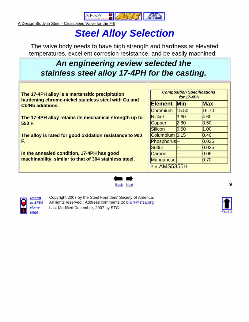
Steel Alloy SelectionThe valve body needs to have high strength and hardness at elevated
temperatures, excellent corrosion resistance, and be easily machined.
An engineering review selected the stainless steel alloy 17-4PH for the casting.
The 17-4PH alloy is a martensitic precipitation hardening chrome-nickel stainless steel with Cu and Cb/Nb additions.
The 17-4PH alloy retains its mechanical strength up to 550 F.
The alloy is rated for good oxidation resistance to 900 F.
In the annealed condition, 17-4PH has good machinability, similar to that of 304 stainless steel.
Composition Specifications
for 17-4PH
Element Min Max Chromium 15.50 16.70 Nickel 3.60 4.60 Copper 2.80 3.50Silicon 0.50 1.00 Columbium 0.15 0.40 Phosphorus -- 0.025 Sulfur -- 0.025 Carbon -- 0.06 Manganese -- 0.70 Per AMS5355H
Back Next 9
Returnto SFSAHome Page
Copyright 2007 by the Steel Founders' Society of America.All rights reserved. Address comments to: [email protected] Modified:December, 2007 by STG
Page 1
A Design Study in Steel - Crossbleed Valve for the F-5
Steel Alloy Selection
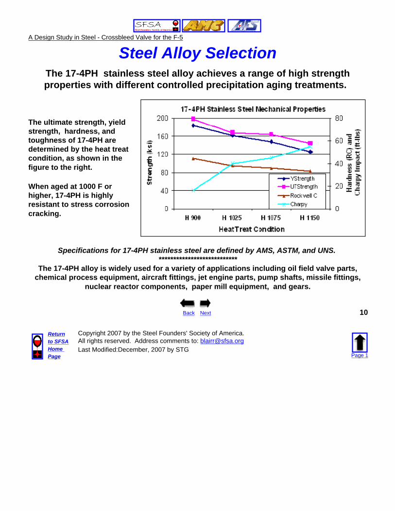
The 17-4PH stainless steel alloy achieves a range of high strength properties with different controlled precipitation aging treatments.
The ultimate strength, yield strength, hardness, and toughness of 17-4PH are determined by the heat treat condition, as shown in the figure to the right.
When aged at 1000 F or higher, 17-4PH is highly resistant to stress corrosion cracking.
Specifications for 17-4PH stainless steel are defined by AMS, ASTM, and UNS. ***************************
The 17-4PH alloy is widely used for a variety of applications including oil field valve parts, chemical process equipment, aircraft fittings, jet engine parts, pump shafts, missile fittings,
nuclear reactor components, paper mill equipment, and gears.
Back Next 10
Returnto SFSAHome Page
Copyright 2007 by the Steel Founders' Society of America.All rights reserved. Address comments to: [email protected] Modified:December, 2007 by STG
Page 1
A Design Study in Steel - Crossbleed Valve for the F-5
Molding Process SelectionMetal casting is the most appropriate forming method for this component, because of the
complexity and thin wall configuration of the part. No other forming method (forging, assembly, welding, etc) could meet the shape and tolerance requirements without extensive
machining and extra cost.
In considering the complexity, physical size, tolerance requirements, cost targets, and limited production quantity for the crossbleed valve, investment casting was the molding process of choice.
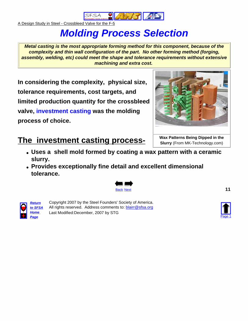
The investment casting process- Wax Patterns Being Dipped in the Slurry (From MK-Technology.com)
● Uses a shell mold formed by coating a wax pattern with a ceramic slurry.
● Provides exceptionally fine detail and excellent dimensional tolerance.
Back Next 11
Returnto SFSAHome Page
Copyright 2007 by the Steel Founders' Society of America.All rights reserved. Address comments to: [email protected] Modified:December, 2007 by STG
Page 1
A Design Study in Steel - Crossbleed Valve for the F-5
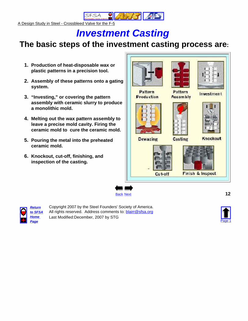
Investment Casting The basic steps of the investment casting process are:
1. Production of heat-disposable wax or plastic patterns in a precision tool.
2. Assembly of these patterns onto a gating system.
3. “Investing,” or covering the pattern assembly with ceramic slurry to produce a monolithic mold.
4. Melting out the wax pattern assembly to leave a precise mold cavity. Firing the ceramic mold to cure the ceramic mold.
5. Pouring the metal into the preheated ceramic mold.
6. Knockout, cut-off, finishing, and inspection of the casting.
Back Next 12
Returnto SFSAHome Page
Copyright 2007 by the Steel Founders' Society of America.All rights reserved. Address comments to: [email protected] Modified:December, 2007 by STG
Page 1
A Design Study in Steel - Crossbleed Valve for the F-5
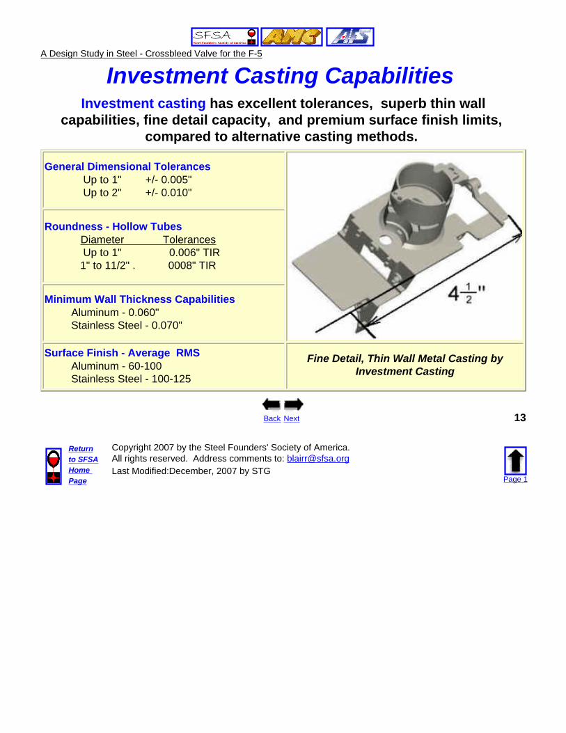
Investment Casting Capabilities Investment casting has excellent tolerances, superb thin wall
capabilities, fine detail capacity, and premium surface finish limits, compared to alternative casting methods.
General Dimensional Tolerances Up to 1" +/- 0.005" Up to 2" +/- 0.010"
Roundness - Hollow Tubes Diameter Tolerances Up to 1" 0.006" TIR 1" to 11/2" . 0008" TIR
Minimum Wall Thickness Capabilities Aluminum - 0.060" Stainless Steel - 0.070"
Surface Finish - Average RMS Aluminum - 60-100 Stainless Steel - 100-125
Fine Detail, Thin Wall Metal Casting by Investment Casting
Back Next 13
Returnto SFSAHome Page
Copyright 2007 by the Steel Founders' Society of America.All rights reserved. Address comments to: [email protected] Modified:December, 2007 by STG
Page 1
A Design Study in Steel - Crossbleed Valve for the F-5
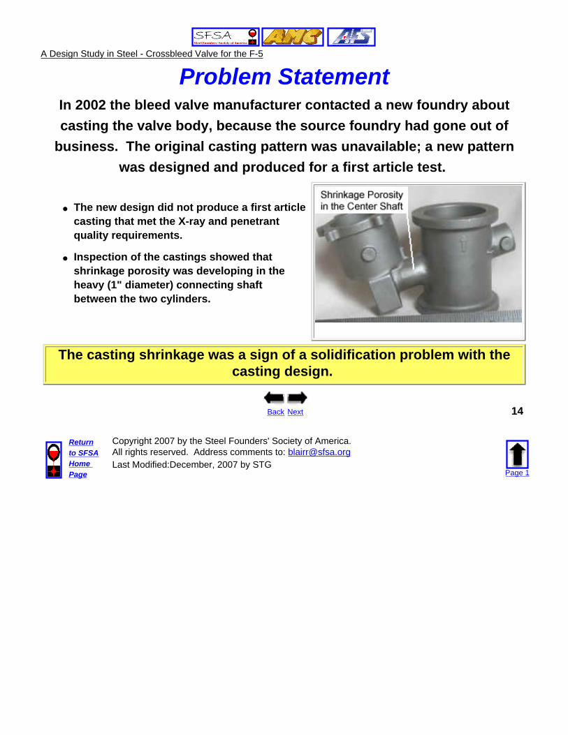
Problem Statement In 2002 the bleed valve manufacturer contacted a new foundry about casting the valve body, because the source foundry had gone out of
business. The original casting pattern was unavailable; a new pattern was designed and produced for a first article test.
● The new design did not produce a first article casting that met the X-ray and penetrant quality requirements.
● Inspection of the castings showed that shrinkage porosity was developing in the heavy (1" diameter) connecting shaft between the two cylinders.
The casting shrinkage was a sign of a solidification problem with the casting design.
Back Next 14
Returnto SFSAHome Page
Copyright 2007 by the Steel Founders' Society of America.All rights reserved. Address comments to: [email protected] Modified:December, 2007 by STG
Page 1
A Design Study in Steel - Crossbleed Valve for the F-5
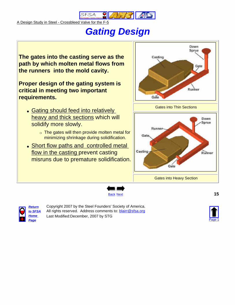
Gating Design
The gates into the casting serve as the path by which molten metal flows from the runners into the mold cavity.
Proper design of the gating system is critical in meeting two important requirements.
● Gating should feed into relatively heavy and thick sections which will solidify more slowly.
❍ The gates will then provide molten metal for minimizing shrinkage during solidification.
● Short flow paths and controlled metal flow in the casting prevent casting misruns due to premature solidification.
Gates into Thin Sections
Gates into Heavy Section
Back Next 15
Returnto SFSAHome Page
Copyright 2007 by the Steel Founders' Society of America.All rights reserved. Address comments to: [email protected] Modified:December, 2007 by STG
Page 1

A Design Study in Steel - Crossbleed Valve for the F-5
Solidification Shrinkage
A review of the casting design pointed
to the casting gating as the primary
reason for shrinkage porosity in the
connecting center shaft.
The tooling design used two gates to feed molten metal into the main cylinder on the top and into the cup on the bottom.
● The thick center shaft was remote from the two gate inlets with no direct metal feed into the heavy section during solidification.
● As the thin-wall cylinder on the top and cup on the bottom solidified, metal feed into the center shaft was restricted and porosity shrinkage formed in the shaft.
Back Next 16
Returnto SFSAHome Page
Copyright 2007 by the Steel Founders' Society of America.All rights reserved. Address comments to: [email protected] Modified:December, 2007 by STG
Page 1
A Design Study in Steel - Crossbleed Valve for the F-5
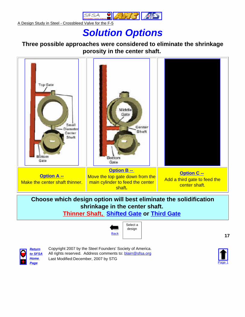
Solution OptionsThree possible approaches were considered to eliminate the shrinkage
porosity in the center shaft.
Option A --Make the center shaft thinner.
Option B -- Move the top gate down from the main cylinder to feed the center
shaft.
Option C -- Add a third gate to feed the
center shaft.
Choose which design option will best eliminate the solidification shrinkage in the center shaft.
Thinner Shaft, Shifted Gate or Third Gate
Back
Select a design
17
Returnto SFSAHome Page
Copyright 2007 by the Steel Founders' Society of America.All rights reserved. Address comments to: [email protected] Modified:December, 2007 by STG
Page 1
A Design Study in Steel - Crossbleed Valve for the F-5
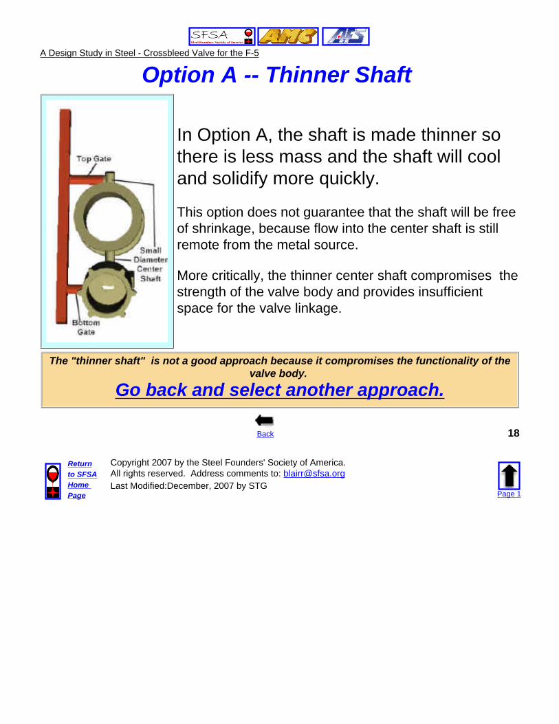
Option A -- Thinner Shaft
In Option A, the shaft is made thinner so there is less mass and the shaft will cool and solidify more quickly.
This option does not guarantee that the shaft will be free of shrinkage, because flow into the center shaft is still remote from the metal source.
More critically, the thinner center shaft compromises the strength of the valve body and provides insufficient space for the valve linkage.
The "thinner shaft" is not a good approach because it compromises the functionality of the valve body.
Go back and select another approach.
Back 18
Returnto SFSAHome Page
Copyright 2007 by the Steel Founders' Society of America.All rights reserved. Address comments to: [email protected] Modified:December, 2007 by STG
Page 1
A Design Study in Steel - Crossbleed Valve for the F-5
Option B -- Move the Gate
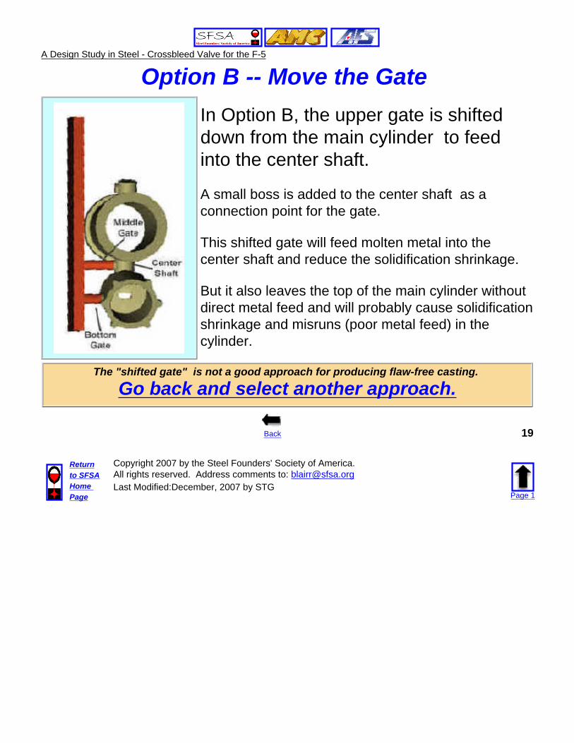
In Option B, the upper gate is shifted down from the main cylinder to feed into the center shaft.
A small boss is added to the center shaft as a connection point for the gate.
This shifted gate will feed molten metal into the center shaft and reduce the solidification shrinkage.
But it also leaves the top of the main cylinder without direct metal feed and will probably cause solidification shrinkage and misruns (poor metal feed) in the cylinder.
The "shifted gate" is not a good approach for producing flaw-free casting.
Go back and select another approach.
Back 19
Returnto SFSAHome Page
Copyright 2007 by the Steel Founders' Society of America.All rights reserved. Address comments to: [email protected] Modified:December, 2007 by STG
Page 1

A Design Study in Steel - Crossbleed Valve for the F-5
Option C -- Third Gate
In Option C, a third gate is added to the casting which feeds directly into the center shaft.
A small boss is added to the center shaft as a connection point for the gate.
This third gate in the middle will provide the center shaft the molten metal needed to eliminate shrinkage porosity during solidification.
The two original gates still provide good metal feed into the top of the main cylinder and the cup.
The "Third Gate" is the best design option for producing a flaw-free casting.
Go on to the next design issue.
Back Next 20
Returnto SFSAHome Page
Copyright 2007 by the Steel Founders' Society of America.All rights reserved. Address comments to: [email protected] Modified:December, 2007 by STG
Page 1
A Design Study in Steel - Crossbleed Valve for the F-5
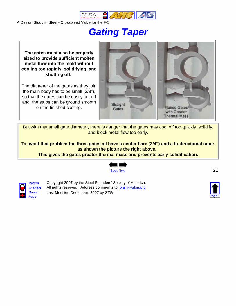
Gating Taper
The gates must also be properly sized to provide sufficient molten metal flow into the mold without
cooling too rapidly, solidifying, and shutting off.
The diameter of the gates as they join the main body has to be small (3/8"), so that the gates can be easily cut off and the stubs can be ground smooth
on the finished casting.
But with that small gate diameter, there is danger that the gates may cool off too quickly, solidify, and block metal flow too early.
To avoid that problem the three gates all have a center flare (3/4") and a bi-directional taper, as shown the picture the right above.
This gives the gates greater thermal mass and prevents early solidification.
Back Next 21
Returnto SFSAHome Page
Copyright 2007 by the Steel Founders' Society of America.All rights reserved. Address comments to: [email protected] Modified:December, 2007 by STG
Page 1
A Design Study in Steel - Crossbleed Valve for the F-5
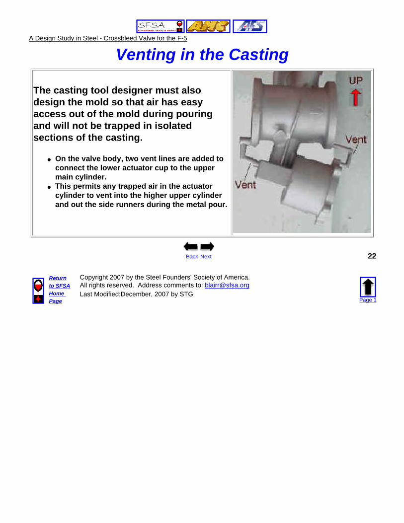
Venting in the Casting
The casting tool designer must also design the mold so that air has easy access out of the mold during pouring and will not be trapped in isolated sections of the casting.
● On the valve body, two vent lines are added to connect the lower actuator cup to the upper main cylinder.
● This permits any trapped air in the actuator cylinder to vent into the higher upper cylinder and out the side runners during the metal pour.
Back Next 22
Returnto SFSAHome Page
Copyright 2007 by the Steel Founders' Society of America.All rights reserved. Address comments to: [email protected] Modified:December, 2007 by STG
Page 1
A Design Study in Steel - Crossbleed Valve for the F-5
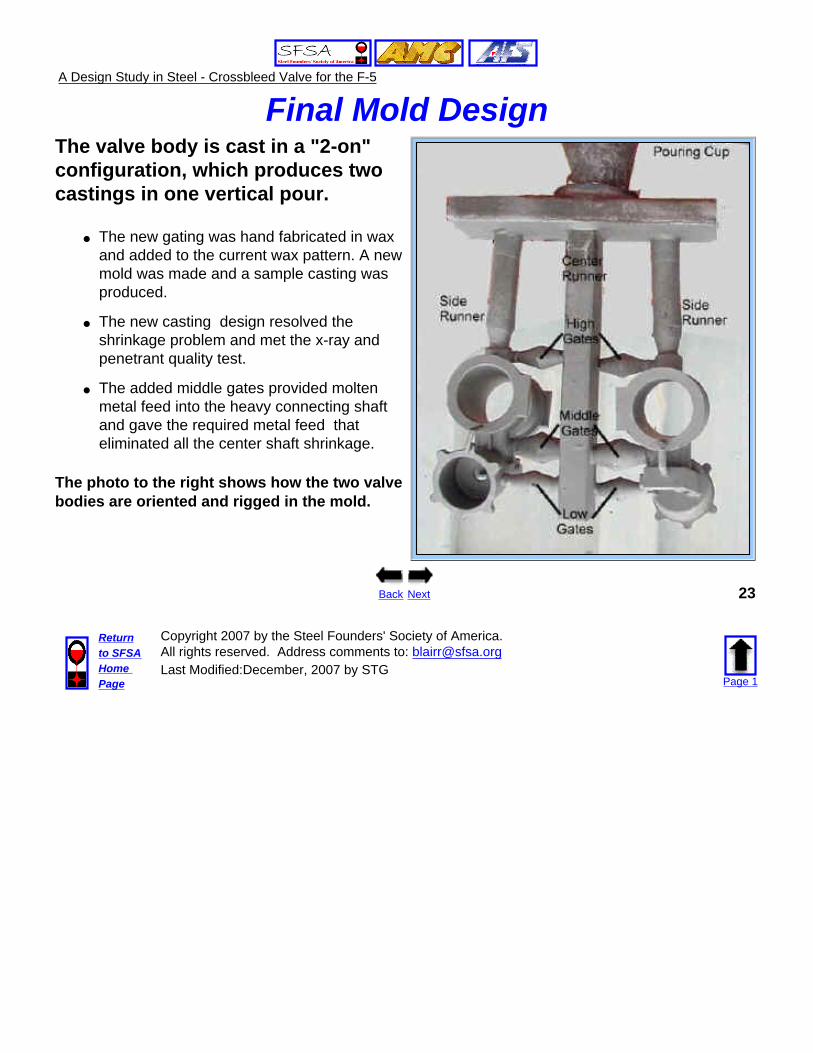
Final Mold Design The valve body is cast in a "2-on" configuration, which produces two castings in one vertical pour.
● The new gating was hand fabricated in wax and added to the current wax pattern. A new mold was made and a sample casting was produced.
● The new casting design resolved the shrinkage problem and met the x-ray and penetrant quality test.
● The added middle gates provided molten metal feed into the heavy connecting shaft and gave the required metal feed that eliminated all the center shaft shrinkage.
The photo to the right shows how the two valve bodies are oriented and rigged in the mold.
Back Next 23
Returnto SFSAHome Page
Copyright 2007 by the Steel Founders' Society of America.All rights reserved. Address comments to: [email protected] Modified:December, 2007 by STG
Page 1
A Design Study in Steel - Crossbleed Valve for the F-5
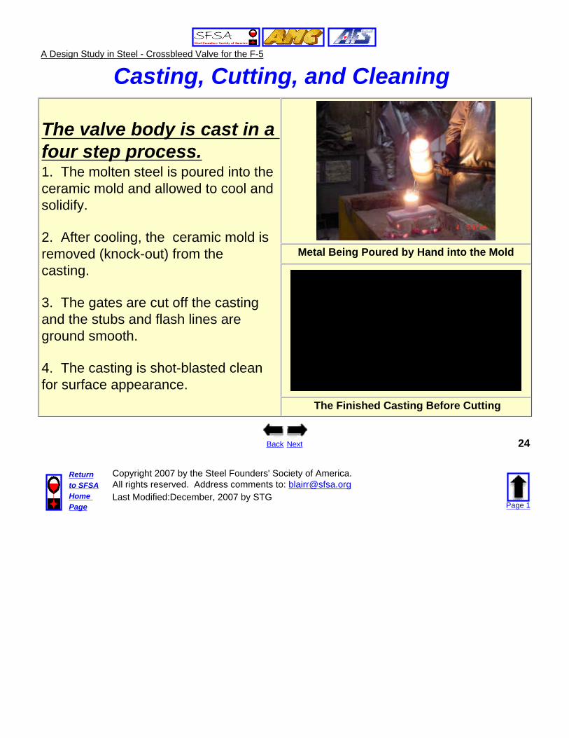
Casting, Cutting, and Cleaning
The valve body is cast in a four step process.1. The molten steel is poured into the ceramic mold and allowed to cool and solidify.
2. After cooling, the ceramic mold is removed (knock-out) from the casting.
3. The gates are cut off the casting and the stubs and flash lines are ground smooth.
4. The casting is shot-blasted clean for surface appearance.
Metal Being Poured by Hand into the Mold
The Finished Casting Before Cutting
Back Next 24
Returnto SFSAHome Page
Copyright 2007 by the Steel Founders' Society of America.All rights reserved. Address comments to: [email protected] Modified:December, 2007 by STG
Page 1
A Design Study in Steel - Crossbleed Valve for the F-5
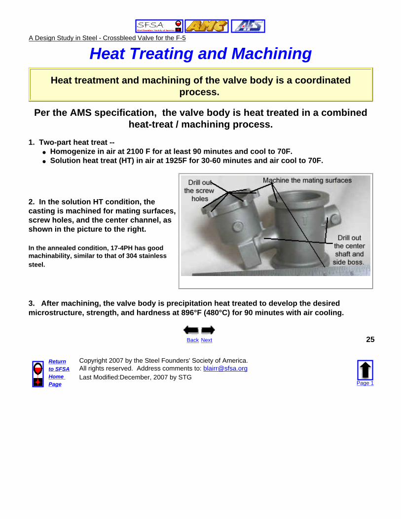
Heat Treating and Machining
Heat treatment and machining of the valve body is a coordinated process.
Per the AMS specification, the valve body is heat treated in a combined heat-treat / machining process.
1. Two-part heat treat -- ● Homogenize in air at 2100 F for at least 90 minutes and cool to 70F.● Solution heat treat (HT) in air at 1925F for 30-60 minutes and air cool to 70F.
2. In the solution HT condition, the casting is machined for mating surfaces, screw holes, and the center channel, as shown in the picture to the right.
In the annealed condition, 17-4PH has good machinability, similar to that of 304 stainless steel.
3. After machining, the valve body is precipitation heat treated to develop the desired microstructure, strength, and hardness at 896°F (480°C) for 90 minutes with air cooling.
Back Next 25
Returnto SFSAHome Page
Copyright 2007 by the Steel Founders' Society of America.All rights reserved. Address comments to: [email protected] Modified:December, 2007 by STG
Page 1
A Design Study in Steel - Crossbleed Valve for the F-5
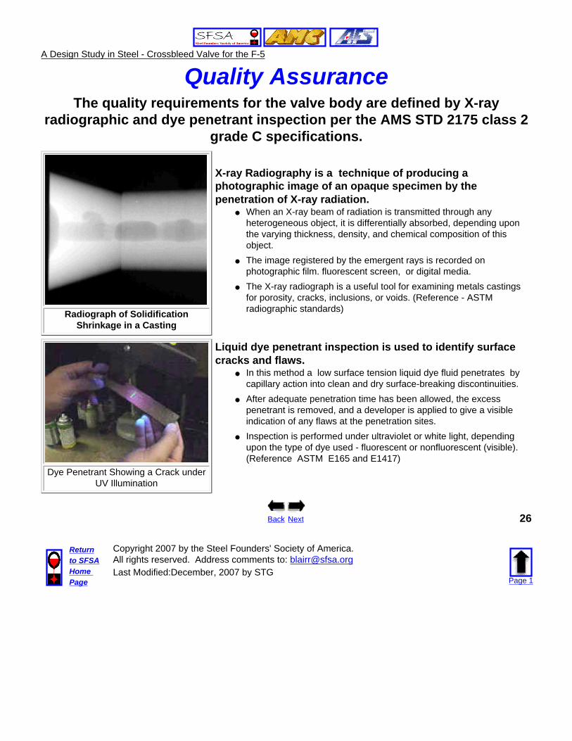
Quality AssuranceThe quality requirements for the valve body are defined by X-ray
radiographic and dye penetrant inspection per the AMS STD 2175 class 2 grade C specifications.
Radiograph of Solidification Shrinkage in a Casting
X-ray Radiography is a technique of producing a photographic image of an opaque specimen by the penetration of X-ray radiation.
● When an X-ray beam of radiation is transmitted through any heterogeneous object, it is differentially absorbed, depending upon the varying thickness, density, and chemical composition of this object.
● The image registered by the emergent rays is recorded on photographic film. fluorescent screen, or digital media.
● The X-ray radiograph is a useful tool for examining metals castings for porosity, cracks, inclusions, or voids. (Reference - ASTM radiographic standards)
Dye Penetrant Showing a Crack under UV Illumination
Liquid dye penetrant inspection is used to identify surface cracks and flaws.
● In this method a low surface tension liquid dye fluid penetrates by capillary action into clean and dry surface-breaking discontinuities.
● After adequate penetration time has been allowed, the excess penetrant is removed, and a developer is applied to give a visible indication of any flaws at the penetration sites.
● Inspection is performed under ultraviolet or white light, depending upon the type of dye used - fluorescent or nonfluorescent (visible). (Reference ASTM E165 and E1417)
Back Next 26
Returnto SFSAHome Page
Copyright 2007 by the Steel Founders' Society of America.All rights reserved. Address comments to: [email protected] Modified:December, 2007 by STG
Page 1
A Design Study in Steel - Crossbleed Valve for the F-5
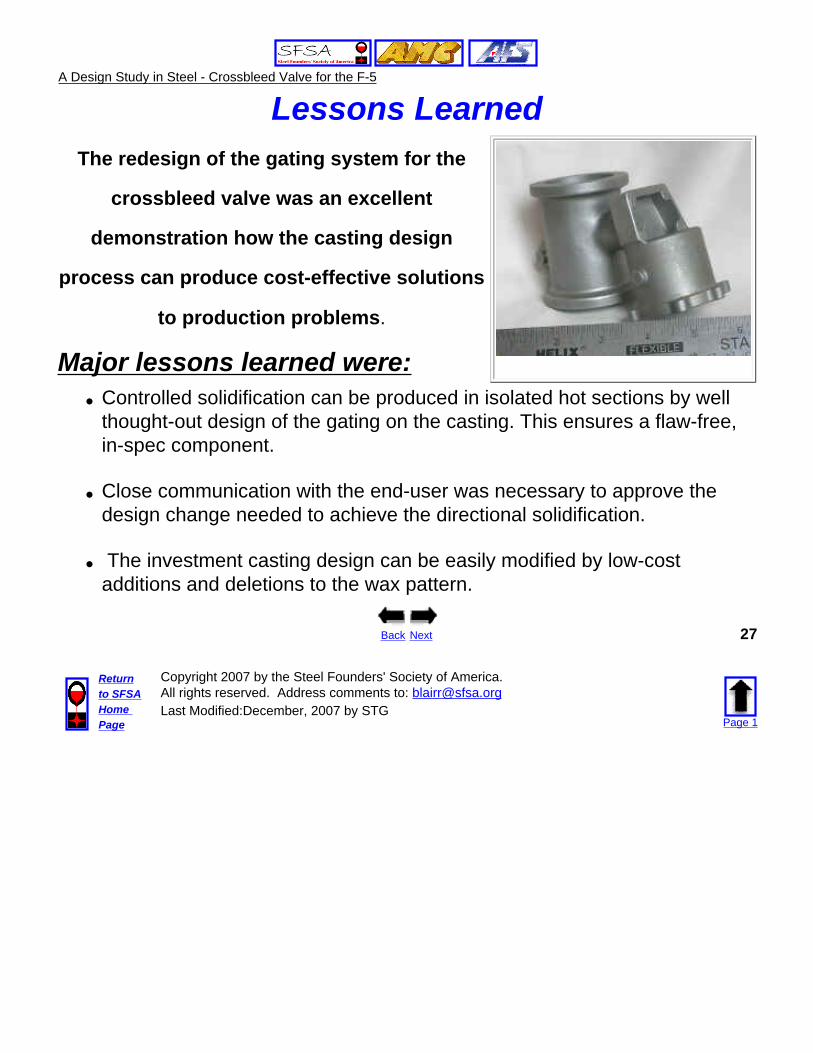
Lessons Learned The redesign of the gating system for the
crossbleed valve was an excellent
demonstration how the casting design
process can produce cost-effective solutions
to production problems.
Major lessons learned were:
● Controlled solidification can be produced in isolated hot sections by well thought-out design of the gating on the casting. This ensures a flaw-free, in-spec component.
● Close communication with the end-user was necessary to approve the design change needed to achieve the directional solidification.
● The investment casting design can be easily modified by low-cost additions and deletions to the wax pattern.
Back Next 27
Returnto SFSAHome Page
Copyright 2007 by the Steel Founders' Society of America.All rights reserved. Address comments to: [email protected] Modified:December, 2007 by STG
Page 1

A Design Study in Steel - Crossbleed Valve for the F-5
Summary
Crossbleed Valve for the F-5 Jet Fighter
The direct benefit of producing the crossbleed valve body as a steel casting is rapid, cost effective production.
The design flexibility, short lead times, near-net shape capability, and rapid production capacity of steel castings met the desired delivery schedule at the target cost, with the required quality and performance
F-5 Fighters
For further information on casting steel alloys, contact -- Gary Burrows on the Metals Team at ATI -- Phone-- 562-397-3151
E-mail: [email protected] Web Site = http://amc.aticorp.org/castitoverview.html
Acknowledgment --The metalcasting design studies are a joint effort of the
Steel Founders' Society of America and the American Foundry Society.Project funding was provided by the American Metalcasting Consortium Project, which
is sponsored by the Defense Logistics Agency, Attn: DLSC-T, Ft. Belvoir, VA, 22060-6221
Back
The End 28
Returnto SFSAHome Page
Copyright 2007 by the Steel Founders' Society of America.All rights reserved. Address comments to: [email protected] Modified:December, 2007 by STG
Page 1