Embed Size (px)
Citation preview
September 1981 A Critical Evaluation ,of Indentation Techniques for Measuring Fracture Toughness: I 533 ’H. P. Kirchner and R. M. Gruver, “Fracture Mirrors in Alumina Ceramics,”
‘H.P. Kirchner, “The Strain Intensity Criterion for Crack Branching in Ce-
’R. W. Rice and W. J. McDonough; “Ambient Strength and Fracture of ZrO,,”
ibid., 27 [6] 1433-46 (1973).
ramics,” Eng. Fracr. Mech. 10 [2] 283-88 (1978).
Mech. Behav. Muter. 394-403 (1972). 6R. C. Garvie, R. H. Hannink, and R. T. Pascoe, “Ceramic Steel?” Nature
(London), 258 155371 703-704 (1975). ‘R.C. Garvie, R. H. J. Hannink, R. R. Hughan, N. A. McKinnon, R. T. Pascoe,
and R. K. Shinger, “Strong and Partially Stabilized Zirconia Ceramics,” J. Aus. Ceram. Soc. 13 [I] 8-11 (1977).
*D. L. Porter and A. H. Heuer, “Mechanisms of Toughening Partially Stabilized Zirconia Ceramics (PSZ),” J. Am. Ceram. Soc., 60 [3-4] 183-84 (1977).
9R.C. Garvie, R .R. Hughan, and R . T . Pascoe; pp. 263-74 in Processing of Crystalline Ceramics, Edited by H. Palmour 111, R. R. Davis, and T. M. Hare. Plenum, New York, 1978.
%.T. Pascoe, R. H. J . Hannink, and R. C. Garvie; pp. 447-54 in Science of Ceramics 9. Edited by K. J . de Vries. Nederlandse Keramische Vereniging, The Netherlands, 1977.
”R. C. Garvie, R. H. J. Hannink, and C. Urbani, ‘.Fracture Mechanics Study of a Transformation Toughened Alloy in the CaO-ZrO, System,” Presented at the 4th ClMTEC Meeting, Saint-Vincent, Italy (May, 1979).
’*T. Gupta; pp. 877-89 in Fracture Mechanics of Ceramics, Vol. 4. Edited by R. C. Bradt, D. P. H. Hasselman, and F. F. Lange. Plenum, New York, 1978. ‘’G. K. Bansal and A. H. Heuer, “Precipitation in Partially Stabilized Zirconia,” J.
Am. Ceram. Soc., 58 [5-61 235-38 (1975). I4N. Claussen, “Comments on ‘Precipitation in Partially Stabilized Zirconia’,”
ibid., 59 [ M I 179 (1976). ”D. L. Porter, G. K. Bansal, and A. H. Heuer, “Reply,” ibid., pp. 17%82. IbR. W. Rice, “Further Discussion Of ‘Precipitation in Partially Stabilized Zir-
conia’.” ibid.. 60 15-61 280 (1977). I’D. L. Porter a d A. H. Heuer,“‘Reply to Further Discussion of ‘Precipitation in
”C. A. Andersson and T. K. Gupta, “Martensitic Transformation Toughening of Partially Stabilized Zirconia’,” ibid., pp. 28C-81,
Zro,”; for abstract see Am. Ceram. SOC. Bull . . 57 131 312 (1978). . _ . ,
1 9 k F. Lange, “Microstructurally Developed Toughening Mechanisms in Ceramics: I, Fracture Toughness,” Rockwell International Science Center Tech. Rept. No. 2 (SC 5117.2TR). Contract NooO14-77-0441 (July, 1978).
*“F. F. Lange, “Stress Induced Martensitic Reaction: 11,” Rockwell Intemation- a l Science Center Tech. Rept. No. 3 (SC 5117.3TR). Contract NOOOl4-77-C-0441
ul , 1978). (J 2h. J. Green, P. S. Nicolson, and J. D. Embury; pp. 541-53 in Fracture Mechanics of Ceramics, Vol. 2. Edited by R. C. Bradt, D. P. H. Hasselman and F. F. Lange. Plenum, New York, 1974.
,,N. Claussen, “Fracture Toughness of Al20, with an Unstabilized ZrO, Dispersed Phase,” J. Am. Ceram. Soc., 59 [1-21 49-51 (1976).
”H. P. Kirchner, R. C. Garvie, R. M. Gruver, and D. M. Richard, “Localized Impact Damage on Transformation Toughened Zirconia,” Muter. Sci. Eng. , 40, 49-57 11979) ._ I, \.,.,,.
24R. F. Pabst; pp. 555-66 in Ref. 21. 25F. W. Smith, A. F. Emery, and A. S. Kobayashi, “Stress-Intensity Factors
for Semicircular Cracks, Part 2 - Semi-Infinite Solid,” J. Appl. Mech., ME, [I21 95L-59 11967).
~~ ~ I-
26A. F. Liu. “Stress Intensity Factor for a Comer Flaw,” Eng. Fract. Mech., 4 175-79 (1972).
”R. T. Pascoe and R. C. Garvie; pp. 774-84 in Ceramic Microstructures ’76. Edited by R. M. Fulrath, Westview Press, Boulder, Colo., 1977.
28J. J. Mecholsky, R. W. Rice, and S. W. Freiman, “Prediction of Fracture Energy and Flaw Size in Glasses from Measurements of Mirror Size,” J. Am. Ceram. Soc., 57 5101 44C-43 (1974).
A. G. Evans, A. H. Heuer, and D. L. Porter, pp. 529-56 in Fracture 1977, Vol. 1. Edited by D. M. R. Taplin. University of Waterloo Press, Waterloo, Canada, 1977.
”E. Hombogen, “Martensitic Transformation at a Propagating Crack,” Acra Metall., 26, 147-52 (1978).
’IG. K. Bansal and W. H. Duckwor!!, “Fracture Stress as Related to Flaw and Fracture Mirror Sizes,” J. Am. Ceram. Soc., 60 17-81 304-10 (1977).
’,H. P. Kirchner and R. M. Gruver, “Fractographic Criteria for Subcritical Crack Growth Boundaries in 96% Alumina.” 63 13-41 16%74 11980). . 1 ~~ ~ - --,
33F. E. Buresh; pp. 835-47 in Ref.’ 12. 34F. W. Kleinlein and H. Hubner; pp. 883-91 in Fracture 1977, Vol. 3. Edited by
D. M. R. TaDlin. Universitv of Waterloo Press. Waterloo. Canada. 1977. a5K. K r i i and F. W. Kfeinlein, “Influence ‘of the Testing-Rate on Slow Crack
Growth in Alumina with Different Grain Sizes,” Ber. Deutsch. Keram. Ges., 57,
36M. V. Swain; to be published in Fracture Mechanics of Ceramics, Vols. 5 & 6. Edited by R. C. Bradt, A. G. Evans, D. P. H. Hasselman, and F. F. Lange. Plenum, New York, 1981.
22-26 (1980).
A Critical Evaluation of Indentation Techniques for Measuring Fracture Toughness: I, Direct Crack Measurements
G . R. ANSTIS, P. CHANTIKUL, B. R. LAWN,* and D. B. MARSHALL *’* Department of Applied Physics, School of Physics, University of New South Wales, New South Wales 2033, Australia
The application of indentation techniques to the evaluation of fracture toughness is examined critically, in two parts. In this flrst part, attention is focused on an approach which involves direct measurement of Vickers-produced radial cracks as a function of indentation load. A theoretical basis for the method is first established, in terms of elasticlplastic indentation frac- ture mechanics. It is thereby asserted that the key to the radial crack response lies In the residual component of the contact fkld. This residual term has important implications concerning the crack evolution, including the possibility of postindentation slow growth under environment-sensitive conditions. Frac- tographic observations of cracks in selected “reference” mater- Ys are used to determine the magnitude of this effect and to investigate other potential complications associated with de- partures from ideal indentation fracture behavior. The data from these observations provide a convenient calibration of the indentation toughness equations for general application to other well-behaved ceramics. The technique is uniquely hp ie in procedure and economic in its use of material.
1. Introduction HE advent of indentation fracture mechanics’ has provided a T fundamental basis for analyzing the apparently complex
deformation/fracture response of ceramics to controlled sharp- contact events .*-Io With this development in analytical under- standing has come a growing realization that the sharp indenter has
Received October 22, 1980 revised copy received March 3, 1981. Supported by the Australian Research Grants Committee, the Australian De-
‘Now with the Materials and Molecular Research Divisiw, Lawrence Berkeley
papent of Defence, and the U. S. Office of Naval Research.
Lboratory. Berkeley, California 94720.
Member, the American Ceramic Society.
considerable potential as a microprobe for quantitatively charac- terizing mechanical properties. In comparison with more conventional testing techniques, the sharp-indenter concept offers a unique simplicity and economy in test procedure, at little cost in reliability. A recent survey of various fracture mechanics methods currently under investigation for applications to brittle materials” is useful for placing indentation fracture in some perspective in this regard.
This study concerns itself with an evaluation of sharp-indenter techniques in the determination of one vitally important fracture parameter for ceramics, namely the toughness K , . Two ap- proaches, presented in separate parts, are examined: in Part I, the determination is made from direct measurements of the crack traces on the indented surfaces, using the indentation fracture theory as a straightforward basis for calculation. In Part II,’* values are ob- tained indirectly from the strengths of indented flexural test pieces, in conjunction with a unified indentation-fracture/tensile- failure formulation. The chief object of the study is to explore the advantages and limitations of each of these two alternative approaches.
The idea that the size of indentation cracks might be used to quantify toughness was actually recognized by Palmqvist, on em- pirical grounds, long before the above-mentioned analytical frac- ture mechanics methods were developed. I3,l4 Palmqvist worked with metal carbides and used a Vickers diamond pyramid indenter to produce the crack patterns. With considerable insight, he was able to establish some of the most important variables in the frac- ture process, including hardness. Extension of the approach to glasses and ceramics has been surprisingly slow in coming. Indeed, the first attempt to use indentation methods for determining frac- ture parameters in more brittle materials was made using the Hertz- ian cone crack geometry produced by spherical
534 Journal of the American Ceramic Society-Anstis et al. Vol. 64, No. 9
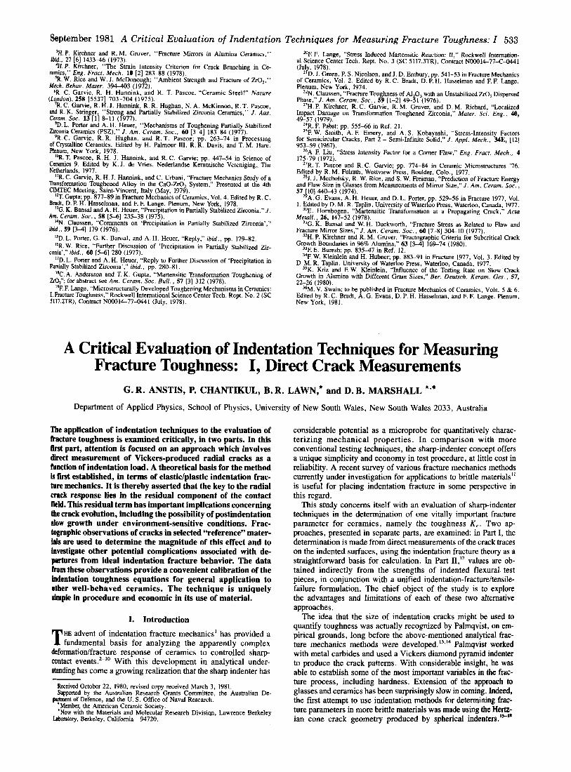
11. Background Theory Figure 1 shows a schematic of the indentation deformation/
fracture pattern for the Vickers geometry: P is the peak load and a and c are characteristic dimensions of the “plastic” impression and the radiahedian crack, respectively. From simplistic dimensional analysis it can be demonstrated that these parameters relate directly to the hardness H and toughness K, of the indented material:
H = P / a d 2 ( la)
t---2c ___/ -I 2at-
Fig. 1. Schematic of Vickers-produced indentation-fracture system, peak load P, showing characteristic dimensions c and a of penny-like radiaymedian crack and hardness impression, respectively.
However, the front of the expanding cone lies entirely beneath the indentation surface, thus limiting direct observations to transparent materials. It is the apparent absence of this limitation in the crack systems associated with Vickers and other sharp indenters which has been primarily responsible for the more recent renewal of inter- est in the Palmqvist notion. The pertinent cracks in this case form on median planes containing the axis of loading and the symmetry axes of the contact hardness impression’”; the characteristic radial traces on the specimen surface conveniently provide a record of the crack growth which is readily amenable to direct post- indentation measurement, and an inherent geometrical similarity in the pattern with pyramidal indenters offers the prospect of valid material comparisons.
have attempted to make direct use of the radial crack pattern for K , determinations in ceramics. However, the underlying theoretical bases of the earlier fracture mechanics treatment^"^ from which these attempts derive are somewhat phe- nomenological in nature, particularly in the accommodation of the inelastic component of the contact field. It is only with subsequent theoretical developments, in which the complex elastic/plastic field is shown to consist essentially of separable “elastic” and “residual” terms, that a proper understanding of the driving forces behind the radial evolution has been Apart from producing a soundly based working relation between indentation variables and material properties, the later theories bring out the key point that the residual component is more than just a “correction” factor in the indentation mechanic^'^^'^; rather, this component assumes a dom- inating role in determining the final size of the radial crack.” The present work critically examines the direct crack measurement ap- proach in this new light, with appropriate attention to reliability and accuracy. The Vickers diamond pyramid is adopted as our standard indenter configuration, because of its general facility for re- producing well-defined radial crack traces on ceramic surfaces .’’ The materials selected for study embrace a broad range of tough- ness values. Independent K, determinations are used to “calibrate” the indentation equations, thereby avoiding the complexities of an absolute computation of geometrical terms in the fracture mechan- ics. Due emphasis is given to certain limitations which are evident in the method; the effects of slow crack growth and crackhicro- structure interactions are important considerations in this respect.
Several
K , = P 1 poc ’I’ where a. and Po are to be regarded as numerical constants: for Vickers indenters a0=2 if a is taken as the impression half- diagonal and if H is identified with the mean contact (load- invariant) pressure; Po corresponds to a complex geometrical factor for penny-like systems, incorporating interaction effects due to the presence of the specimen free surface, multiple-plane crack con- figuration, etc., and is usually determined by experimental cali- bration. To this point the description is purely phenomenological, i n that no physical understanding of the mechanics of deformatiodfracture evolution is required.
In addition to the radialimedian crack system depicted in Fig. 1, a second, so-called ‘‘lateral’’ system (not shown) is usually gener- ated.’ The lateral cracks spread outward from the deformation zone, beneath the indentation surface, and may interact with the radial system. In severely loaded specimens they turn upward to intersect the surface, thereby causing severe disruption of the pat- tern by chipping. The analysis which follows is confined to loads below the chipping threshold, and proceeds on the assumption that any IateraUradial interactions may be accommodated within a con- stant Po term.
Explicit models of radial crack evolution within the elastic/ plastic field of a sharp indenter, for an isotropic, homogeneous material, have recently thrown new light on the interpre- tation of Eq. (l).’-’’ The field contributes two superposable components to the net driving force on the crack system, viz. an elastic (reversible) and a residual (irreversible) component. At the indentation surface the elastic component is compressive, the re- sidual component tensile. Thus the radial cracks grow to their final lengths as the indenter is unloaded, i.e. as the restraining elastic field is removed. (The downward, “median” crack behaves some- what differently. ’’) The residual driving force is therefore primarily responsible for expanding the crack system into its ultimate penny- like configuration. For sufficiently well-developed cracks, c %, the pennies may be considered to be “center-loaded” at the defor- mation zone, in which case the driving force may be suitably char- acterized by a residual stress intensity factor of the simple form3
K , = x , P / c 3 ” (2) where x. is a constant. Detailed consideration of the manner in which the volume of the plastic impression is accommodated by the surrounding elastic matrix shows that this “constant” depends on the ratio of Young’s modulus to hardness, E / H , to the one-half power approximately,”
(3) where §; is a material-independent constant for Vickers-produced radial cracks (replacing the quantity $(cot 4~)’” defined in Ref. 10). It is apparent that “softer” ceramics, i.e. those with lower values of H I E , will experience greater residual driving forces.
Equations (2) and (3) provide the basis for any postindentation fracture mechanics analysis. Suppose first that the crack system is subject to conditions of mechanical equilibrium both during and after the contact event, such that the radial cracks remain stable at K,=K,. Denoting c =co as the crack dimension appropriate to this postindentation equilibrium configuration, we obtain
(4) as our basic equation for evaluating material toughness. Com- parison with Eq. ( lb ) indicates that Po relates to the intrinsic stress/strain response of the indented material, as reflected by the parameters in Eq. (3), which gives rise to the residual crack- opening forces. Given information on these parameters, it follows
K , = x P /c03/‘= $ t ( E /H)”’(P / c F )
September 1981 A Critical Evaluation of Indentation Techniques for Measuring Fracture Toughness: I 535
Table I. Materials Used in Indentation Toughness Studies Grain size
Material Characterization (w) E ( G W H(GF‘a) K,(MF‘am”2) Toughness measurement‘
Glass-ceramic (C9606)” Glass-ceramic 1 108 8.4 2.5 DCB (standard) Soda-lime glass I~ ‘
Soda-lime glass II’ Aluminosilicate glass‘ Lead alkali glass‘ A1203 (AD999Jd &03 (AD901 A1203 (Viy & 0 3 (sapphire)’
Si3N4 (NC132)8 Si3N4 (NC350)g
SiC(NC203)8
ZrO (Ca-stabilized)” Si’
WC (Co-bonded)‘
Amorphous Amorphous Amorphous Amorphous Polycry stal Polycrystal Polycrystal Monocrystal-’
Polycrystal Polycrystal
Polycrystal
Pol ycrystal Monocry stalk
Polvcrvstal
3 4
20
2 10
4
50
3
70 73 89 65
406 390 305 425
300 170
436
210 168
575
5.5 5.6 6.6 4.9
20.1 13.1 19.1 21.8
18.5 9.6
24.0
10.0 10.6
13.2
0.74 0.75 0.91 0.68 3.9 2.9 4.6 2.1
4.0 2.0
4.0
7.6 0.7
12
DCB (standard) DCB (standard) (Ref. 27) DCB (standard) (Ref. 27) DCB (standard) (Ref. 27) DCB (standard) DCB (standard) DCB (D. B. Marshall) DT (A. G. Evans’ and E. A. Charles,’ Ref. 20)
DCB (standard) DT (S . M. Wiederhorn* and
N. J. Tighe*) DT (S. M. Wiederhorn* and
N. J. Tighe*) DCB (D. B. Marshall) DT (S. M. Wiederhorn’ and
E. R. Fuller*) DT (S. W. Freiman?
d .
‘Pyroceram: Corning Glass Works, Corning, N. Y.b Commercial sheet glass. Wational Bureau of Standards, Washington, D. C. “Coors Porcelain Co., Golden, Colo. ‘Vistal, Cms Furcelain Co. bride, Union Carbide Co., New York, N. Y. BNorton Co., Worcester, Mass. CSIRO, Australia. ‘Texas Instruments, Inc., Dallas. ’Rods, [OOOl] 30” to axis. W k s [Ill] parallel to axis. ’DT=double torsion, DCB=double cantilever beam. ‘University of California, Berkeley. ‘Rockwell International Science Center, Thousand Oaks, Calif. *National Bureau of Standards.
that K, is obtainable from measurements of the crack size co after contact as a function of the peak load P.
If, on the other hand, equilibrium conditions do not prevail, Eq. (4) is no longer valid. Slow crack growth effects (to which many ceramics are. susceptible) become an important factor. In the event that such effects cause the radial crack to extend beyond co, to c ’o say, then the residual stress intensity factor diminishes, in accord- ance withEqs. (2) and (4), to K , = X ~ P / ~ ’ ~ ~ ~ ~ = K ~ ( C ~ / C ‘ ~ ) ~ ~ ~ . + Thus, depending on the interval between completion of the contact cycle and measurement of the cracks, the effective toughness determined may be somewhat less than the true Kc. Since crack velocity is generally a strongly increasing function of stress intensity factor, it is to be expected that the most significant kinetic effects will occur immediately after unloading, making systematic discrepancies dif- ficult to avoid.
Implicit in the preceding analysis is the assumption that the crack patterns remain geometrically well behaved at all times. In “real” ceramics several factors militate against this assumption. For in- stance, the underlying basis for the derivation of Eqs. (2) and (3), and thence Eq. (4), is that the material beneath the indenter deforms readily at constant volume.” Not all solids behave in this way: at low values of H / E the displaced material tends to pile up around the indenter (e.g. soft metals)25; in solids with relatively open network structures the material tends instead to densify (e.g. “anomalous” silicate glasses).26 In these cases the shape of the cracks, as well as the size, may be significantly affected. It is important also to ensure that the indenter geometry itself is invari- ant, to reproduce the deformation response from material to mater- ial. For this purpose the Vickers diamond pyramid, being elastically hard and readily attainable as a standard accessory with any routine hardness testing facility, is ideally suited. (Due caution should thus be exercised in comparing results obtained using a Vickers indenter with those using, say, a Knoop indenter.”) Vari- ants in crack-interaction effects, e.g. the radial/lateral interactions already mentioned, might also be expected to reflect in the results. Most important in relation to practical ceramics, however, is the influence of microstructure on the crack pattern. The typical radial crack dimension is = 100 pm, so materials with inhomogeneity on a scale >1 pm will be subject to fluctuations in co, hence in the measured K c . As the coarseness of the microstructure becomes comparable with the size of the indentation, the fracture pattern is more susceptible to disruption from local grain-failure events.21 At the same time, crystalline anisotropy assumes increasing im-
‘Assuming that x, remains constant. This assumption is questioned in Part I1
portance; in the limit of a grain size larger than the indentation the pattern becomes representative of the monocrystalline state.
111. Experimental
(1) Materials and Procedure The materials chosen for study are listed in Table I. Several
criteria were used in compiling this list. First, the range of tough- ness values covered should be broad enough to allow for maximum confidence in c o n f d n g theoretically predicted trends. Second, the materials should be representative of practical ceramics, em- bracing monocrystalline, polycrystalline, and amorphous solids. Third, the list should contain materials which could be used as a reference for calibrating the toughness equations. Fourth, “model” materials for exploratory testing in establishing a routine mea- surement procedure and for assessing the influence of micro- structure should be included.
Most of the ceramic specimens were received with machined surfaces. With these materials the machining damage was removed mechanically by polishing, ultimately with 1 pm diamond paste, to produce an optical finish. The glass and sapphire (flame-polished) specimens needed no such preparation, their surfaces being mirror smooth as a direct result of the fabrication history. However, in the case of glass the specimens were subjected to an annealing treat- ment to remove any built-in surface stresses. All specimens came in slab form (bars, disks) with flat, parallel surfaces, except for sapphire, which came as rods.
Most of the Vickers indentations were made using a routine hardness testing facility. A special fixture attached to the stage of an inverted microscope was used in some of the exploratory tests on glass (see below). Care was taken to maintain the indentation axis parallel to the surface normal of each specimen but no attempt was made to control the indentedspecimen orientation about this axis, even with the monocrystalline materials. Where it was con- sidered desirable to minimize slow crack growth effects from mois- ture in the atmosphere, a drop of immersion oil was placed on the prospective contact site. The indented surfaces were then examined by high-power optical microscopy, in reflected polarized light, and the characteristic dimensions accordingly measured as averages over the two orthogonal radial directions. For this purpose it was an advantage to place a cover slide on the oil-indented surfaces, except for high-magnification viewing, when an oil-immersion objective was used. The loads used were restricted to a range over which the indentation patterns remained well defined; at the lower end by the minimum requirement c 2 2 a for validity of Eq. (2), at the upper
536 Journal of the American Ceramic Society-Anstis et al. Vol. 64, No. 9
300 I I I I 1 I I
250
E 3 200 \ - 0 V
150 I I
I I I 1 I I
100 102 1 0 L 106
Time after indentation, t I s
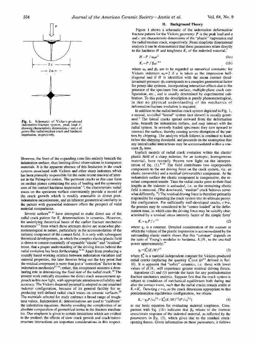
Fig. 2. Variation of radial crack length, c ’,,, with time after indentation (P=40 N) for tests on soda-lime glass in air and oil environments. Shaded band shows immediate postindentation crack length, co.
end by chipping or by the limitation of specimen thickness (to avoid interactions with the lower free surface, the crack dimensions were not allowed to exceed one-tenth of the thickness).
The hardness and modulus were determined routinely for each material in Table I, H directly from Eq. (la) as the mean overall indentation, and E from the elastic deflections in 4-point bending (monitored by resistance strain gages). An accuracy of >5% was obtained for each of these two quantities. Toughness measurements were made on selected “reference” ceramics using the double can- tilever techniquez8 (designated in the table as DCB standard): with a nominal accuracy of 10%. In the case of the glass-ceramic,’ the value Kc=2.5 MPa-rn’” may be compared with 2.1 to 2.6 MPa.m’lz obtained by four independent workers using the same source mater- ial.’ For the remaining materials in Table I, representative values from the literature or from independent workers are quoted, with an assumed nominal accuracy of 20% in the case of polycrystals and 40% in the case of monocrystals (the latter being subject to aniso- tropic variation). (2) Exploratory Tests
It was indicated in Section I1 that the validity of Eq. (4) as a toughness formula was subject to certain qualifications, connected with slow crack growth and microstructure. Exploratory tests were consequently run to examine the importance of these qualifications.
The first set of tests was run on commercial soda-lime glass using an indentation arrangement which enabled the crack evo- lution to be followed in situ from below during and after the con- tact.’ With this setup the indenter was taken to maximum load via an electric motor drive for =I0 s, then rapidly unloaded manually in < I s in order that the time origin for the onset of moisture- assisted post indentation slow crack growth should be accurately fixed. (By virtue of the residual stress birefringence, the crack tips remain clearly visible, even when oil enters along the crack inter- face.) The observed crack size for several cracks tested in oil and air environments is plotted as a function of time after completion of contact in Fig. 2: the plot is for a contact load P =40 N, with the initial equilibrium size co (shaded band) determined as the extrapo- lation of the oil data back to t =O. Without attempting to deal with the explicit kinetics here, it is immediately evident that substantial errors in the toughness evaluation will be incurred if the cracks are not measured immediately after indentation. This is most apparent in the air data but even in oil, generally regarded as a relatively inert test medium, the effect is significant.
At no stage during the contact did the lateral front extend beyond
*At the National Bureau of Standards, Washington, D. C., in collaboration with
Pyroceram C9606, Coming Glass Works, Coming, N. Y. S. I. Bums, B. G. Koepke, L. M. Barker, and M. Srinivasan, as part of a round-
robin toughness evaluation program, subcommittee E24.07, American Society for Testing Materials.
S . M. Wiederhom and S. W. Freiman.
the radial front, suggesting that the contribution of interaction terms to the constants in Eqs. (1) and (4) is probably not great. (If the laterals were to precede the radials in the evolution, the radials would be unable to extend downward into the characteristic penny- like geometry, in which case the indentation configuration would be entirely different, and the interaction term accordingly of para- mount importance.) On the other hand, the lateral cracks did tend to grow more extensively in postindentation slow crack growth, until ultimately (after =1 h in oil) they caught up with the radidmedian front. Accordingly, while apparently not a crucial factor in the surface crack measurements required for the present work, laterauradial interactions will need to be reconsidered in the analysis of remaining strength in Part 11.”
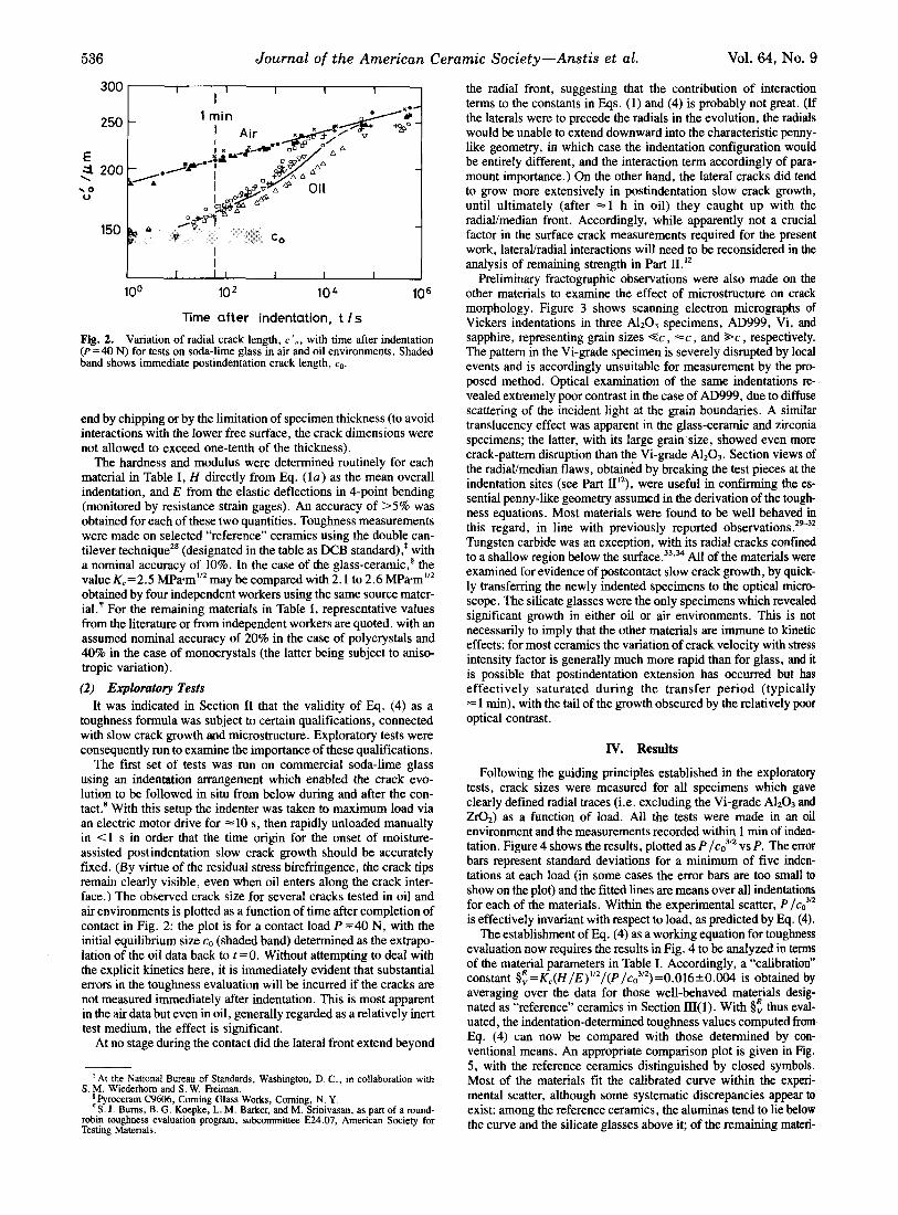
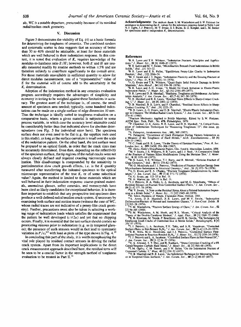
Preliminary fractographic observations were also made on the other materials to examine the effect of microstructure on crack morphology. Figure 3 shows scanning electron micrographs of Vickers indentations in three A1203 specimens, AD999, Vi, and sapphire, representing grain sizes e c , =c , and *c , respectively. The pattern in the Vi-grade specimen is severely disrupted by local events and is accordingly unsuitable for measurement by the pro- posed method. Optical examination of the same indentations re- vealed extremely poor contrast in the case of AD999, due to diffuse scattering of the incident light at the grain boundaries. A similar translucency effect was apparent in the glass-ceramic and zirconia specimens; the latter, with its large grain size, showed even more crack-pattern disruption than the Vi-grade A1,0,. Section views of the radiaumedian flaws, obtained by breaking the test pieces at the indentation sites (see Part 111*), were useful in confirming the es- sential penny-like geometry assumed in the derivation of the tough- ness equations. Most materials were found to be well behaved in this regard, in line with previously reported observations .2e32
Tungsten carbide was an exception, with its radial cracks confined to a shallow region below the surface.33.” All of the materials were examined for evidence of postcontact slow crack growth, by quick- ly transferring the newly indented specimens to the optical micro- scope. The silicate glasses were the only specimens which revealed significant growth in either oil or air environments. This is not necessarily to imply that the other materials are immune to kinetic effects: for most ceramics the variation of crack velocity with stress intensity factor is generally much more rapid than for glass, and it is possible that postindentation extension has occurred but has effectively saturated during the transfer period (typically = 1 min), with the tail of the growth obscured by the relatively poor optical contrast.
IV. Results
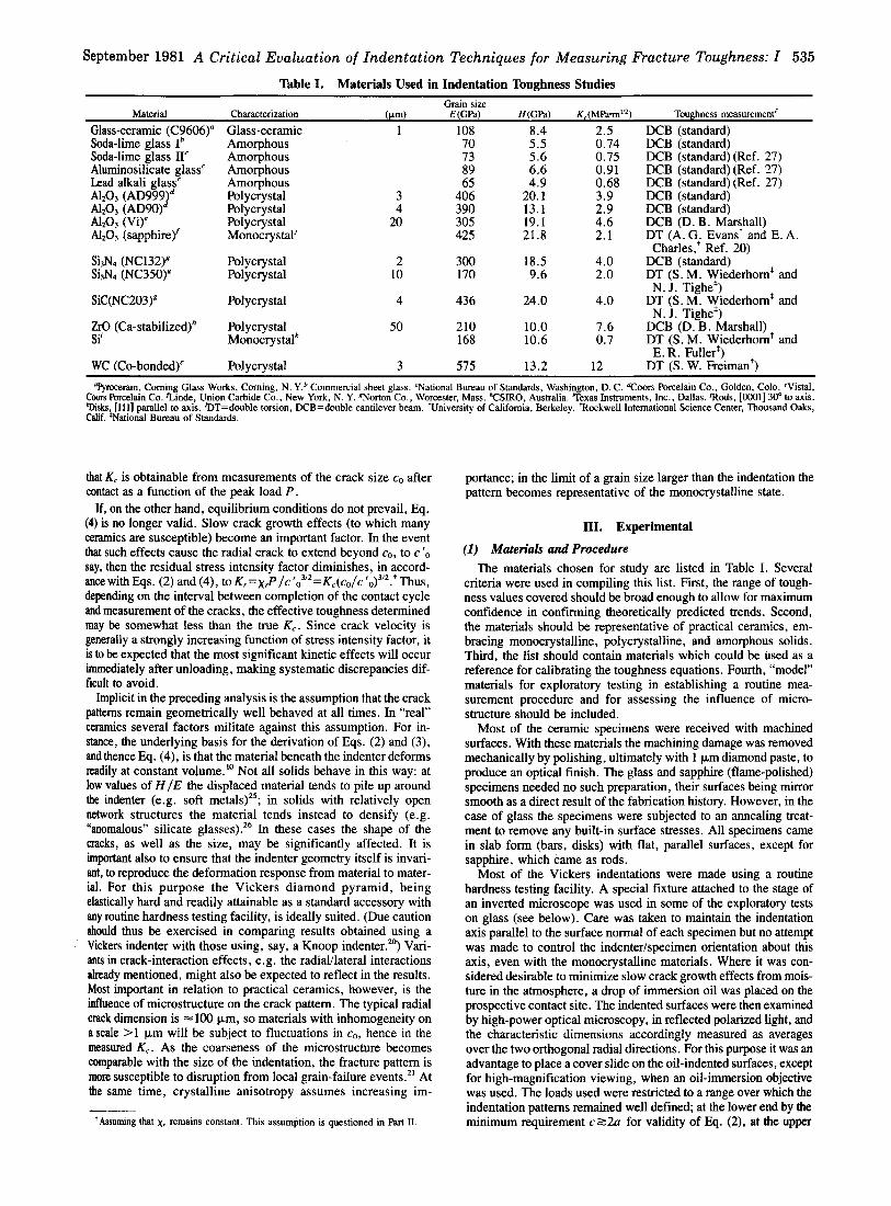
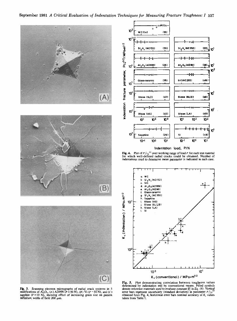
Following the guiding principles established in the exploratory tests, crack sizes were measured for all specimens which gave clearly defined radial traces (i.e. excluding the Vi-grade A1203 and Zro,) as a function of load. All the tests were made in an oil environment and the measurements recorded within 1 min of inden- tation. Figure 4 shows the results, plotted as P /c03/* vs P. The error bars represent standard deviations for a minimum of five inden- tations at each load (in some cases the error bars are too small to show on the plot) and the fitted lines are means over all indentations for each of the materials. Within the experimental scatter, P /co)n is effectively invariant with respect to load, as predicted by Eq. (4).
The establishment of Eq. (4) as a working equation for toughness evaluation now requires the results in Fig. 4 to be analyzed in terms of the material parameters in Table I. Accordingly, a “calibration” constant $~=Kc(H/E)”Z/(P/co3/2)=0.016~0.004 is obtained by averaging over the data for those well-behaved materials desig- nated as “reference” ceramics in Section III( 1). With thus eval- uated, the indentation-determined toughness values computed from Eq. (4) can now be compared with those determined by con- ventional means. An appropriate comparison plot is given in Fig. 5, with the reference ceramics distinguished by closed symbols. Most of the materials fit the calibrated curve within the experi- mental scatter, although some systematic discrepancies appear to exist: among the reference ceramics, the aluminas tend to lie below the curve and the silicate glasses above it; of the remaining materi-
September 1981 A Critical Evaluation of Indentation Techniques for Measuring Fracture Toughness: I 537
102F
L 1
r ocQooo-
WC(Co1 O (101 I
Ti Si N,INC1321 1301 6 n
N n
516 N, INC3501 122 I
A I q 0 , IADQOI 1391
E l W 2 SlClNC2031
lo'
10-1 100 l o 1 lo-1 100 lo'
Indentailon Load, PIN Fig. 4. Plot of P / c ~ over working range of load P for each test material for which well-defined radial cracks could be obtained. Number of indentations used to determine mean parameter is indicated in each case.
b Si3NLlNC1321 c. Sic
*. A l ~ O ~ I A 0 9 0 1 u t Glass-ceramic / ._ - g. SI3N,(NC3SOI
2 1 0 1 i . Glass lASl
I k . Gloss I L A I "E - \ I. Si
h. Sapphire
j. Glass ISLLXI I
o c
* I .
/ /
1 0 0 10'
K c (conventional) I MPa*m"2 F'ig. 5. Plot demonstrating correlation between toughness values determined by indentation and by conventional means. Filled symbols denote reference materials used to evaluate constant 0; in E q . (4). Vertical error bars represent uncertainty (standard deviation) in parameter PIC? obtained from Fig. 4, horizontal error bars nominal accuracy of K, values taken from Table I.
Fig. 3. Scanning electron micrographs of radial crack systems in 3 modifications of Al2O3, ( A ) AD999 (P =50 N), (B) Vi (P=50 N), and ( C ) sapphire (!'=lo N), showing effect of increasing grain size on pattern definition; width of field 200 Wm.
538 Journal of the American Ceramic Society-Anstis et al. Vol. 64, No. 9
als, WC is a notable departure, presumably because of its nonideal radiavmedian crack geometq.
V. Discussion
Figure 5 demonstrates the viability of Eq. (4) as a basic formula for determining the toughness of ceramics. The combined random and systematic scatter in data suggests that an accuracy of better than 30 to 40% should be attainable, at least for those materials which are well behaved in their indentation response. In this con- text, it is noted that evaluation of K, requires knowledge of the modulus-to-hardness ratio E / H ; however, both E and H are usu- ally measured readily by routine methods to within +5% and are therefore unlikely to contribute significantly to the overall error. For those materials unavailable in sufficient quantity to allow for direct modulus measurement, use of a “representative” value of E for the material will of course add to the uncertainty in the K, determination.
Adoption of the indentation method in any ceramics evaluation program accordingly requires the advantages of simplicity and economy in testing to be weighed against these limitations in accu- racy. The greatest asset of the technique is, of course, the small amount of specimen area needed; typically, some hundred inden- tations can be made on a single surface of edge dimension 10 mm. Thus the technique is ideally suited to toughness evaluation on a comparative basis, where a given material is subjected to some process variable, in which case the accuracy level attainable could be considerably better than that indicated above for absolute deter- minations (see Fig. 5 for individual error bars). The specimen surface does not even need to be flat (e.g. the sapphire rods used in this study), as long as the surface curvature is small over the scale of the indentation pattern. On the other hand, the test surface must be prepared to an optical finish, in order that the crack sizes may be accurately determined. Even then, depending on the reflectivity of the specimen surface, the tip regions of the radial cracks were not always clearly defined and required exacting microscopic exam- ination. This disadvantage is compounded by the sensitivity to postindentation slow crack growth effects, i.e. is the K quantity measured after transferring the indented specimen to the optical microscope representative of the true K, or of some subcritical value? Again, the method is limited to those materials which are well behaved in their indentation response: coarse-grained materi- als, anomalous glasses, softer ceramics, and monocrystals have been cited as likely candidates for exceptional behavior. It is there- fore important to establish that any prospective test specimen does produce a well-defined radial/median crack system, if necessary by examining both surface and section traces (witness the case of WC, whose radial traces are not indicative of a penny-like crack geom- etry). Further, precautions must also be taken in selecting a work- ing range of indentation loads which satisfies the requirement that the pattern be well developed ( c 2 2 a ) and yet that no chipping occurs. Finally, it is essential that the test surface should contain no preexisting stresses prior to indentation (e.g. as in tempered glass- es); the presence of such stresses would in fact lead to systematic variation in P /cd“ with load in plots of the type shown in Fig. 4.35
In concluding this part of the study, it is worth reemphasizing the vital role played by residual contact stresses in driving the radial crack system. Apart from its important implications in the direct crack measurement approach described here, the residual term will be seen to be a crucial factor in the strength method of toughness evaluation to be treated in Part 11.”
Acknowledgments: The authors thank S . M. Wiederhorn and S. W. Freiman for assistance in determining the K, values for the reference ceramics listed in Table 1 and N. J. Tighe, J. J. Petrovic, M. V. Swain, S. J. Bums, B. G. Koepke, and L. M. Barker for specimens and/or independent K, determinations.
References ‘B. R. Lawn and T. R. Wilshaw, “Indentation Fracture: Principles and Applica-
2B. R. Lawn and M. V. Swain. “Microfracture Beneath Point Indentations in Brittle tions,” J. Mater. Sci., 10 161 1049-81 (1975).
Solids,” ibid., [l] 113-22.
Fracture,” ibid., 1121 2016-24.
Glass.” J. Phvs. D. 9 1151 2201-14 (1976).
’B. R. Lawn and E. R. Fuller, “Equilibrium Penny-Like Cracks in lndentation
‘M. V. Swain and J . T. Hagan, “Indentation Plasticity and the Ensuing Fracture of
’A.’G. Evak and T.k.’Wilshaw, “Quasi-Static Solid Particle Damage in Brittle
6B.R. Lawn and A.G. Evans, “A Model for Crack Initiation in Elastic/Plastic
’B. R. Lawn and D. B. Marshall, “Hardness, Toughness and Brittleness: An Inden-
*D. B. Marshall and B. R. Lawn, ”Residual Stress Effects in Sharptontact Crack-
D. B. Marshall. B. R. Lawn, and P. Chantikul. “Residual Stress Effects in Sham-
Materials,” Acta Metall., 24 1101 939-56 (1976).
Indentation Fields,” J. Muter. Sci., I2 [ l l ] 2195-99 (1977).
tation Analysis,” J. Am. Ceram. Soc., 62 [7-81 347-50 (1979).
in$: I,” J. Muter. Sci., 14 [8] 2001-12 (1979).
Contact Cracking: 11,” ibid., 19) 2225-35. log. R. Lawn, A. G. Evans, and D. B. Marshall, “ElasticPlastic Indentation Dam-
age in Ceramics: The MediadRadial Crack System,” J. Am. Ceram. Soc., 63 [%lo] T-LM m 8 m - _ _ \ .___
”Fracture Mechanics Applied to Brittle Materials. Edited by S . W. Freiman. ASTM Spec. Tech. Publ., No. 678, Philadelphia, 1979.
I2P. Chantikul, G. R. Anstis, B. R. Lawn, and D. B. Marshall, “A Critical Evalu- ation of Indentation Techniques for Measuring Toughness: 11”: this issue, pp. 53943.
l3S. Palmqvist, Jernkontorets Ann. , 141, 300 (1957). I4S. Palmqvist, ”Occurrence of Crack Format$n During Vicken Indentation as
a Measure of the Toughness of Hard Metals, Arch. Eisenhuttenwes., 33 [61 629-33 (1962).
C. Frank and B. R. Lawn, “On the Theory of Hertzian Fracture,”Proc. R. Soc. London Sect. A, 299 [1458] 291-306 (1967).
16H. Hertz, Hertz’s Miscellaneous Papers, Chs. 5 and 6. Macmillan, London, 18%. I’M. V. Swain, I. S. Williams, B. R. Lawn, and J. J. Beek, “A Comparative Study
of the Frachlre of Various Silica Modifications Using the Hertzian Test,” J. Muter. Sci., 8 [8] 115S64 (1973).
”B. R. Lawn, T. R. Wilshaw, T. 1. Bany. and R. Morrell, “Hertzian Fracture of Glass Ceramics,” ibid., 10 [l] 17%82 (1975).
19M. G. Mendiratta and J. J. Petrovic, “Prediction of Fracture Surface Energy from Microhardness Indentation in Structural Ceramics,” ibid., 11 151 97576 (1976).
”A. G. Evans and E. A. Charles, “Fracture Toughness Determinations by Inden- tation.” J. Am. Ceram. Soc.. 59 17-81 371-72 (19761.
, I
21A: G. Evans; pp. 112-35’in Ref. il. ZZR. H. Marion; pp. 10S11 in Ref. 11. 23J. J. Petrovic. R. A. Dirks. L. A. Jacobson. and M. G. Mendiratta. “Effects of
Residual Stresses’on Fracture from Controlled Sbrface Flaws,”J. Am. Ceram. Soc., 59 h3-41 177-78 (1976).
M. V. Swain, “A Note on the Residual Stress About a Pointed Indentation Impres- sion in a Brittle Solid,’’ J. Muter. Sci., 11 [I21 2345-48 (1976).
*’D. Tabor, Hardness of Metals. Clarendon Ress, Oxford, 1951. 26A. Arora, D. B. Marshall, B. R. Lawn, and M. V. Swain, “Indentation
Deformation/Fracture of Normal and Anomalous Glasses,” J. Non-Cryst. Solids. 31 [3\915-28 (1979).
’ S . M. Wiederhorn, “Fracture Surface Energy of Glass,’’ J. Am. Ceram. Soc., 52 [2\9%105 (1969).
‘ S . M. Wiederhorn, A.M. Shorb, and R. L. Moses, “Critical Analysis of the Theory of the Double Cantilever Method,” J . Appl. Phys . , 39 [3] 156%72 (1968).
29K. R. Kinsman, M. Yessik, P. Beardmore, and R. K. Govila, “On Techniques for Emplacing Small Cracks of Controlled Size in Brittle Solids,” Metaiiography, 8 [41
MJ. I. Petrovic, L. A. Jacobson, P. K. Talty, and A. K. Vasudevan, “Controlled Surface Flaws in Hot-Ressed Si3N4,” J. Am. Ceram. Soc., 58 [3-4] 113-16 (1975).
”R. R. Wills, M. G. Mendiratta, and J. J. ktrovic. “Controlled Surface Flaw- Initiated Fracture in Reaction-Bonded Si3N4,” J. Mater. Sci., 11 [7] 1330-34 (1976).
)*J. J. Petrovic and L. A. Jacobson. “Controlled Surface Flaws in Hot-Pressed Sic,”
351-57 (1975).
J . Am. Ceram. Soc.. 59 [I-21 34-37 (1976).
CobalVIhgsten Carbide Hard Metal,” J. Muter. Sci., 11 [3] 56568 (1976).
Cemented Carbide: I.” Wear. 43 121 23%52 (1977).
”E. A. Almond, A. T. May, and B. Roebuck, “Stress Corrosion Cracking of a 6%
%I. M. Ogilvy, C. M Perrott, and J. W. Suiter, “On the Indentation Fracture of
35D. B. Marshall &d B. R.‘Lawk,>‘‘An Indentation Techni ue for Measuring Stress- es in Tempered Glass Surfaces,” J. Am. Ceram. Soc., 60 Tl-21 86-87 (1977).


