Embed Size (px)
Citation preview
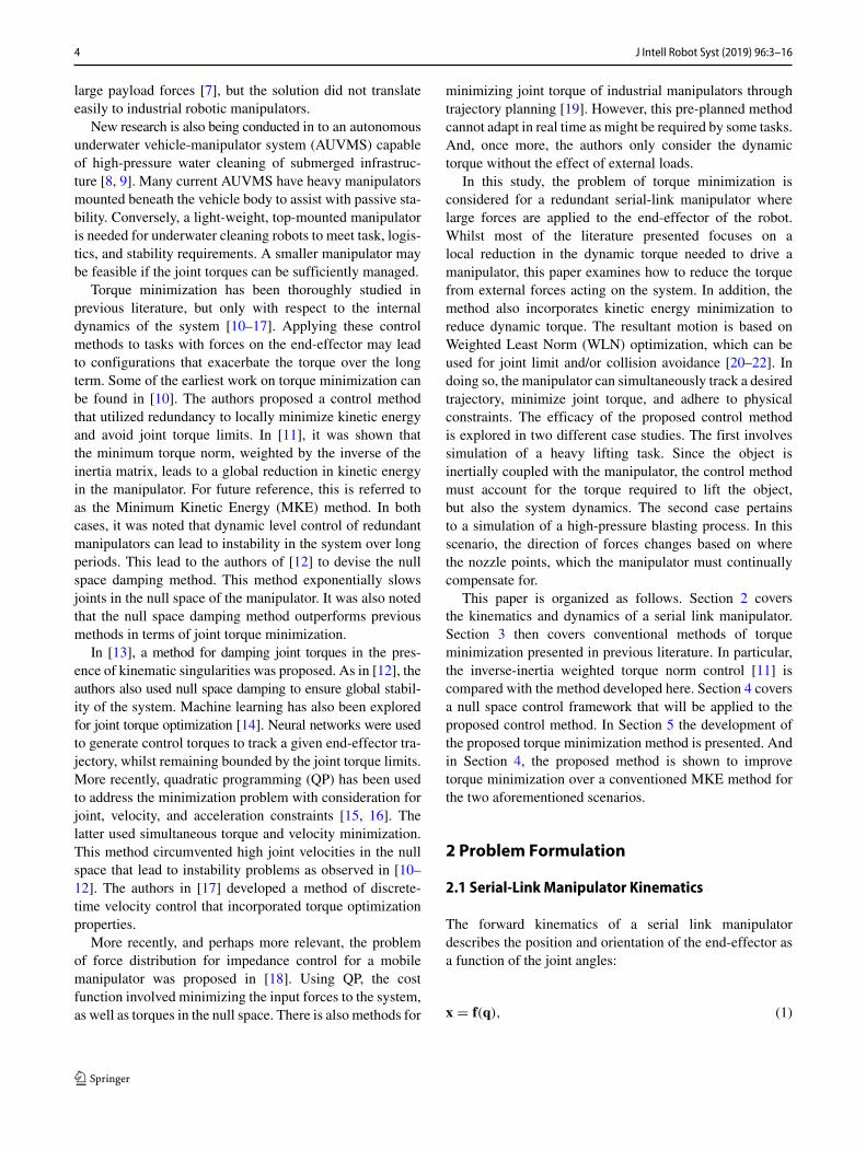
Journal of Intelligent & Robotic Systems (2019) 96:3–16https://doi.org/10.1007/s10846-018-0964-8
A Control Method for Joint Torque Minimization of RedundantManipulators Handling Large External Forces
JonWoolfrey1 ·Wenjie Lu1 ·Dikai Liu1
Received: 15 March 2018 / Accepted: 29 November 2018 / Published online: 11 January 2019© The Author(s) 2019
AbstractIn this paper, a control method is developed for minimizing joint torque on a redundant manipulator where an external forceacts on the end-effector. Using null space control, the redundant task is designed to minimize the torque required to opposethe external force, and reduce the dynamic torque. Furthermore, the joint motion can be weighted to factor in physicalconstraints such as joint limits, collision avoidance, etc. Conventional methods for joint torque minimization only considerthe internal dynamics of the manipulator. If external forces acting on the end-effector are inadvertently implemented in tothese control methods this could lead to joint configurations that amplify the resulting joint torque. The proposed controlmethod is verified through two different case studies. The first case study involves simulation of high-pressure blasting. Thesecond is a simulation of a manipulator lifting and moving a heavy object. The results show that the proposed control methodreduces overall joint torque compared to conventional methods. Furthermore, the joint torque is minimized such that thereis potential for a manipulator to execute certain tasks beyond its nominal payload capacity.
Keywords Null space control · Dynamic control · Optimization · Robotic manipulator · Redundancy · Torque minimization
1 Introduction
The utility of robotic manipulators is in their ability to carryout laborious tasks that involve interactions with objects, ornegotiating with various external forces. This can includetasks such as lifting, pushing/pulling, bracing the manipu-lator against external shocks, or carrying out high-pressureblasting for cleaning surfaces. External forces on the end-effector introduce additional joint torque alongside the inter-nal dynamic torque during task execution. Furthermore,there may be cases in which the manipulator is requiredto work at or above its nominal payload capacity. In suchinstances, careful control of the joint configuration is neces-sary to keep joint torques within appropriate limits.
Generally, the payload capacity of a manipulator must bebalanced against other requirements such as size, weight,workspace volume, dexterity, and degrees of freedom [1].As such, it is not always possible to increase payload capacitywithout sacrificing other performance measures. Therefore,
� Jon [email protected]
1 University of Technology Sydney, 81 Broadway,Ultimo, 2007, NSW, Australia
prudent control of the manipulator can reduce joint torquerequired for the task given these constraints. Redundantmanipulators are capable of self motion, and this propertycan be exploited [2]. It is possible to reconfigure themanipulator such that it can transmit applied forces throughthe structure, and thus minimize torque on the joints.
The problem of robotic grit-blasting makes for an inter-esting case study of this problem. A robotic system for blast-ing and maintenance of the iconic Sydney Harbour Bridgehad been developed at the University of Technology Sydney(UTS) [3]. A Denso VM manipulator was used originally,which had an advertised payload capacity of 13kg [4].Furthermore, the end-effector must be kept at a specificpose when operating above 11kg. The nozzle reaction forcesduring the grit-blasting process reached an estimated 106N(10.8kg) due to the high fluid velocities involved. Conse-quently, there were noted control issues during field experi-ments due to the ”heavily laden manipulator” [5]. This largemanipulator was originally chosen to cope with the highpayload requirements. However, its size conflicted with therestrictions in the working environment due to the confinedworkspace it needed to operate within [3]. The mass of themanipulator was also raised as an issue, due to the frequencywith which it had to be repositioned in the environment [6].Some research had been conducted in anticipation of these
4 J Intell Robot Syst (2019) 96:3–16
large payload forces [7], but the solution did not translateeasily to industrial robotic manipulators.
New research is also being conducted in to an autonomousunderwater vehicle-manipulator system (AUVMS) capableof high-pressure water cleaning of submerged infrastruc-ture [8, 9]. Many current AUVMS have heavy manipulatorsmounted beneath the vehicle body to assist with passive sta-bility. Conversely, a light-weight, top-mounted manipulatoris needed for underwater cleaning robots to meet task, logis-tics, and stability requirements. A smaller manipulator maybe feasible if the joint torques can be sufficiently managed.
Torque minimization has been thoroughly studied inprevious literature, but only with respect to the internaldynamics of the system [10–17]. Applying these controlmethods to tasks with forces on the end-effector may leadto configurations that exacerbate the torque over the longterm. Some of the earliest work on torque minimization canbe found in [10]. The authors proposed a control methodthat utilized redundancy to locally minimize kinetic energyand avoid joint torque limits. In [11], it was shown thatthe minimum torque norm, weighted by the inverse of theinertia matrix, leads to a global reduction in kinetic energyin the manipulator. For future reference, this is referred toas the Minimum Kinetic Energy (MKE) method. In bothcases, it was noted that dynamic level control of redundantmanipulators can lead to instability in the system over longperiods. This lead to the authors of [12] to devise the nullspace damping method. This method exponentially slowsjoints in the null space of the manipulator. It was also notedthat the null space damping method outperforms previousmethods in terms of joint torque minimization.
In [13], a method for damping joint torques in the pres-ence of kinematic singularities was proposed. As in [12], theauthors also used null space damping to ensure global stabil-ity of the system. Machine learning has also been exploredfor joint torque optimization [14]. Neural networks were usedto generate control torques to track a given end-effector tra-jectory, whilst remaining bounded by the joint torque limits.More recently, quadratic programming (QP) has been usedto address the minimization problem with consideration forjoint, velocity, and acceleration constraints [15, 16]. Thelatter used simultaneous torque and velocity minimization.This method circumvented high joint velocities in the nullspace that lead to instability problems as observed in [10–12]. The authors in [17] developed a method of discrete-time velocity control that incorporated torque optimizationproperties.
More recently, and perhaps more relevant, the problemof force distribution for impedance control for a mobilemanipulator was proposed in [18]. Using QP, the costfunction involved minimizing the input forces to the system,as well as torques in the null space. There is also methods for
minimizing joint torque of industrial manipulators throughtrajectory planning [19]. However, this pre-planned methodcannot adapt in real time as might be required by some tasks.And, once more, the authors only consider the dynamictorque without the effect of external loads.
In this study, the problem of torque minimization isconsidered for a redundant serial-link manipulator wherelarge forces are applied to the end-effector of the robot.Whilst most of the literature presented focuses on alocal reduction in the dynamic torque needed to drive amanipulator, this paper examines how to reduce the torquefrom external forces acting on the system. In addition, themethod also incorporates kinetic energy minimization toreduce dynamic torque. The resultant motion is based onWeighted Least Norm (WLN) optimization, which can beused for joint limit and/or collision avoidance [20–22]. Indoing so, the manipulator can simultaneously track a desiredtrajectory, minimize joint torque, and adhere to physicalconstraints. The efficacy of the proposed control methodis explored in two different case studies. The first involvessimulation of a heavy lifting task. Since the object isinertially coupled with the manipulator, the control methodmust account for the torque required to lift the object,but also the system dynamics. The second case pertainsto a simulation of a high-pressure blasting process. In thisscenario, the direction of forces changes based on wherethe nozzle points, which the manipulator must continuallycompensate for.
This paper is organized as follows. Section 2 coversthe kinematics and dynamics of a serial link manipulator.Section 3 then covers conventional methods of torqueminimization presented in previous literature. In particular,the inverse-inertia weighted torque norm control [11] iscompared with the method developed here. Section 4 coversa null space control framework that will be applied to theproposed control method. In Section 5 the development ofthe proposed torque minimization method is presented. Andin Section 4, the proposed method is shown to improvetorque minimization over a conventioned MKE method forthe two aforementioned scenarios.
2 Problem Formulation
2.1 Serial-LinkManipulator Kinematics
The forward kinematics of a serial link manipulatordescribes the position and orientation of the end-effector asa function of the joint angles:
x = f(q), (1)
J Intell Robot Syst (2019) 96:3–16 5
where x ∈ Rm is a vector denoting the pose of the
end-effector, and q ∈ Rn is a vector of joint angles.
Differentiating (1) with respect to time leads to:
x = (∂f/∂q
)q (2)
= J(q)q (3)
x = J(q)q + J(q, q)q, (4)
where J(q) ∈ Rm×n is the Jacobian matrix for the
manipulator. The vector x denoting the primary task is theend-effector acceleration required to track a given trajectory.If m < n, and the Jacobian has full row rank, then there areinfinite joint accelerations q to achieve the required end-effector motion. Based on this, it is possible to solve anoptimization problem of the form:
minq
(q − q2)TW(q − q2) (5)
subject to: x − Jq − Jq = 0. (6)
The solution can be derived via Lagrange multipliers, whichyields the result:
q = J†W(x − Jq
) + NWq2, (7)
where:
– q2 ∈ Rn are joint accelerations defining a secondary,
redundant task to be achieved only after x is satisfied,– W ∈ R
n×n is a positive-definite weighting matrix,– J†W = W−1JT
(JW−1JT
)−1 is the weighted, pseudo-inverse Jacobian, and
– NW = I − J†WJ is the weighted null space matrix.
Note that multiplying (7) through by the Jacobian results inJq = x − Jq, and hence the kinematic relationship in Eq. 4is preserved. The task defined by q2 will have no effect onthe end-effector motion.
In some instances, J†W becomes ill-conditioned as themanipulator approaches a singularity. The pseudoinverseJacobian can be modified using the well-known Damped-Least-Squares (DLS) approach [23]:
J†W,DLS = W−1JT(JW−1JT + λI)−1, (8)
where λ is a scalar damping coefficient. This can beattenuated based on proximity to a singular configuration tomitigate task error [24].
2.2 Manipulator Dynamics
From a desired joint acceleration (7), the subsequent jointtorques can be calculated from the manipulator dynamics:
τ = M(q)q + c(q, q) + g(q) + τE(q) (9)
where:
– M(q) ∈ Rn×n is the inertia matrix,
– c(q, q) ∈ Rn is the vector of Coriolis and centripetal
torques,– g(q) ∈ R
n is the gravity torque vector, and– τE(q) ∈ R
n is a vector of joint torques contributed froman external load on the end-effector.
The vector of joint torques produced from a wrenchon the end-effector, ν ∈ R
m, can be calculated from themanipulator Jacobian. Assuming a static configuration, andfor some infinitesimally small displacements of �x and �q,it holds that:
�x = J�q. (10)
Then from the principle of virtual work, the change in totalenergy of the system must be zero:
�E = νT0�x − τTE�q = 0, (11)
where τE is a vector of torques needed to oppose saidwrench. Substituting (10) in (11), and solving for τE:
ν0J�q = τTE�q (12)
τE = JTν0 (13)
= JTRiνi , (14)
where νi is the wrench referenced in some arbitrary frame{i}, and Ri ∈ SO(m) is a rotation from the manipulator baseframe {0} to {i}. For m = 6, this rotation matrix can bedefined as:
Ri �[Ri0(q) 03×3
03×3 Ri0(q)
], (15)
with Ri0(q) ∈ SO(3) being a rotation dependent on the joint
configuration q, as it exists somewhere on the kinematicstructure of the manipulator.
It is evident from Eq. 14 that the joint torques needed tooppose an external loading on the manipulator is dependenton the joint state. By using redundancy in the system, it ispossible to reconfigure the joints to reduce the magnitudeof the torque vector τE. The objective in this paper is tofind a combination of joint accelerations q to achieve twooutcomes. Firstly, to track a required end-effector trajectory.Secondly, to minimize both the torques required to opposeforces on the end-effector and the dynamic torque requiredto move the manipulator itself.
3 Conventional Methods for TorqueMinimization
Most literature on torque minimization only considersthe internal dynamics of the manipulator system. The
6 J Intell Robot Syst (2019) 96:3–16
introduction of large forces via τE to these control methods(in partcular, the MKE method) does not always lead toa reduction in the total joint torque over the long term.This can be seen from the simulation results in Section 6.Furthermore, much of the early work did not account forphysical constraints on the system. Some QP methodswere devised that incorporated constraints on joint position,velocity, and acceleration [15, 16]. A disdvantage to such aformulation is the lack of a closed-form solution.
3.1 TorqueMinimization in the Null Space
In [10], a control method was proposed to locally minimizekinetic energy needed to control a redundant manipulator, aswell as keep joint torques in the middle of its performancerange. This resulted in the secondary redundant task q2 (7)as follows:
q2 = (W
12MN
)†(W12τmax + τmin
2
). (16)
The diagonal elements ofW were assigned based on torquelimits for each joint. The author noted that this local kineticenergy minimization can lead to long-term instability in thesystem due to high joint velocities.
3.2 MinimumKinetic Energy (MKE) Method
The MKE method, developed in [11], formed a foundationfor later work in the area of torque minimization. Thismethod solves a constrained optimization problem of theform:
minq
½τTM−1τ (17)
subject to: x − Jq − Jq = 0. (18)
By substituting (9) in to (17), and solving via Lagrangemultipliers, the solution is:
q = J†M(x − Jq) − NMM−1(c + τE) (19)
This result is equivalent to Eq. 7 in which W ≡ M andq2 ≡ M−1(c+τE). As in [11], the gravity torque g has beenremoved. This way, the manipulator configuration does notdroop as it attempts to reduce the gravitational potentialenergy in the system. Furthermore, the original formulationdid not include the term τE. It was shown in [11], thatEq. 19, sans τE, leads to a global minimization of kineticenergy in the manipulator system. This will be later used asa baseline to compare with the control method developed inthis paper.
3.3 Null Space DampingMethod
It has been noted that the joint control equation of theform given in Eq. 7 is inherently unstable as the null space
velocities remain uncontrolled. That is, any combination ofjoints that do not contribute to the end-effector motion canmove freely which can make the system unstable. The nullspace damping method was proposed in [12] to address thisissue. This involved a modification to the MKE method toensure stability. A damping term is simply appended to theredundant task like so:
q = J†M(x − Jq) − NM(M−1(c + τE) + βq
), (20)
for some scalar β > 0. Thus, any uncontrolled joints in thenull space will slow down exponentially [12]. The authorsclaimed that this extension also improved torque reductionover the original MKE method.
3.4 Simultaneous Velocity and TorqueMinimization
Due to the phenomena of high joint velocities that appearfrom kinetic energy minimization, the authors of [16]proposed a dual velocity and torque minimization:
min½(αqTq + βτTτ
). (21)
This was solved via QP, with constraints on the jointposition, velocity, and torque. Their results showed thattorque minimization can be achieved whilst preventingdramatic increases in the joint velocities. Again, it oughtto be noted that these four methods only consider theinternal dynamics of the manipulator, and do not account forexternal loading.
4 Null Space Stability and Control
To address null space instability, the authors in [25] deviseda method to control the null space velocities to a desiredstate. The advantage with this method is the ability tooptimize a performance criterion as a function of thejoint state, much like [2]. The control scheme is brieflypresented here, and in Section 5 the framework is appliedto simultaneously minimize torque for trajectory trackingwhilst incorporating physical system constraints. First, thecontrol accelerations can be defined as:
q = J†(x − Jq) + qN, (22)
where qN ∈ Rn is a redundant task such that JqN = 0,
and J† is the unweighted Moore-Penrose pseudoinverseJacobian. To control the null space velocities, the followingwas proposed [25]:
qN = N(qd + KNeN) − (J† + J†JJ†)J(qd − q), (23)
J Intell Robot Syst (2019) 96:3–16 7
where:
– qd is the desired joint velocity,– N is the unweighted null space matrix, that is N ≡ NW
for W = I,– KN is a positive-definite gain matrix, and– eN = N(qd − q) is the joint velocity error projected on
to the null space.
By taking the time derivative of eN, and substituting inEqs. 22 and 23:
eN = N(qd − q) − J†JeN − (J† + J†JJ†)J(qd − q) (24)
= N(qd − qN) − J†JeN − (J† + J†JJ†)J(qd − q) (25)
= −NKNeN − J†JeN. (26)
A Lyapunov candidate function can be defined as the sum-of-squared errors:
V = ½eTNeN, (27)
then the time-derivative is:
V = eTNeN= −eTNNKNeN − eTNJ
†JeN= −eTNKNeN, (28)
since N is symmetric and idempotent, and JN = NJ† = 0.Equation 28 is negative ifKN is positive-definite, and henceq converges to qd in the space of N.
5 Control Method for TorqueMinimizationwith External Loading
In this section, a new control method is proposed tominimize the joint torque with forces on the manipulator’send-effector. This method builds on the null space velocitycontrol in Section 4. This ensures stability, and circumventsthe fictitious damping forces in the null space dampingmethod that interferes with the redundant task. Ratherthan locally minimizing the total torque, as per the MKEmethod, the objective function is defined as a weighted sum.The first component is to minimize the norm of torquesneeded to oppose the forces on the end-effector. The secondcomponent minimizes dynamic torque. In this manner, themanipulator will align itself against the external force, butalso minimize the effort required to achieve this.
5.1 Derivation of Desired Velocity, Acceleration
To stabilize the null space velocities, a desired joint velocitymust be defined. In [25], the desired velocity was equivalentto the task for maximimizing manipulability. Here, thedesired velocity is constructed via the WLN solution to thedifferential kinematics (7). This way, both the main task
and redundant task can be made to conform to physicalconstraints. The desired joint velocity and its time-derivativecan be expressed generally as:
qd = J†Wx + NWy (29)
qd = J†W(x − Jy
) + J†W
(x − Jy
) + NWy, (30)
where the secondary task y, y ∈ Rn is formulated as a sum
of two components that will be used to minimize the staticand dynamic torque components:
y = α1y1 + α2y2, (31)
in which α1 and α2 are scalars to weight the two vectors.Also, multiplying (30) through by the Jacobian yields Jqd =x− Jqd thus maintaining the kinematic relationship denotedby Eq. 4. Note that it is possible to define qd = y, butby Eq. 29 the joints can be made to comply with physicalconstraints through J†W.
By taking y1 as proportional to the gradient vector ofsome scalar cost function h(q), the application of Eq. 29 willoptimize this in the null space of the manipulator:
y1 = ∇h(q). (32)
Choosing α1 < 0 in Eq. 31 will minimize h(q). This isotherwise known as the Gradient Projection Method (GPM)[2]. Its time derivative is then:
y1 = d
dt
(∇h(q))
(33)
= d
dq
(∇h(q))q (34)
= H(q)q, (35)
where H(q) is the Hessian matrix of h(q).To minimize the joint torques caused by a wrench νi on
the manipulator, consider the following cost function:
h(q) = ½τTEGτE (36)
where:
– τE = JTRiνi,– νi = νi/‖νi‖ is the unit vector of νi which defines its
direction, and– G ∈ R
n×n is a positive-definite weighting matrix usedto give priority to joints with higher torque capacity, orbetter mechanical advantage.
The gradient of Eq. 36 with respect to q is:
∇h(q) = (∂ τE/∂q
)TGτE (37)
∂h
∂qj= νTi
(∂RT
i
∂qjJ + RT
i∂J∂qj
)GJTRiνi, j ∈ {1, ..., n}.
(38)
8 J Intell Robot Syst (2019) 96:3–16
The Hessian for Eq. 36 is difficult to calculate, so for prac-tical purposes it is sufficient to use backwards differencingto approximate the time-derivative:
y1(t) ≈ �t−1(y1(t) − y1(t − �t)), (39)
where �t−1 is the control frequency.The joint motion in the redundant portion of the
manipulator from y1, y1 may locally increase the dynamictorque. Therefore, the second portion of the redundant taskcan be used to reduce the local accelerations caused by thetorque components c and τE:
y2 = −M−1(c + τE). (40)
To find the velocity level term for this second vector,discrete-time integration can be used:
y2(t) ≈ y2(t − �t) + �ty2(t − �t). (41)
This second vector component y2 is similar to the MKEmethod (19). Equation 31 is thus a weighted sum betweenminimizing the norm of τE and reducing the local dynamictorque. The scalars α1 and α2 can be chosen based on therelative magnitude of the corresponding torques.
5.2 Incorporation of Physical Constraints
The control equations (7), (29), and (30) represent aweighted-least-norm solution for the joint motion. It ispossible to account for physical constraints in the solutionvia the construction of the weighting matrix W. Someexamples include joint limit avoidance [20], self-collisionavoidance [21], and obstacle avoidance [22]. In this paper,W is constructed for joint limit avoidance as per [20].The weighting matrix is modified using the following costfunction:
d(qi) = (qi,max − qi,min)(2qi − qi,max − qi,min)
γi(qi,max − qi)2(qi − qi,min)2, (42)
in which magnitude of this function grows to infinity nearjoint limits, causing joints to slow down in their approach.In this paper, the joint limit cost function is combined withthe inertia matrixM:
Wij = Mij ∀i �= j (43)
Wii ={Mii + |d(qi)| for �d(qi) > 0
Mii otherwise(44)
The inertia component of this weighting matrix will helpminimize the kinetic energy in the manipulator. Further-more, the element Wii will approach infinity as a joint
moves toward its limit. Thus through Eqs. 29 and 30, jointsmoving away from their limits will be given preference inthe solution.
6 Case Studies
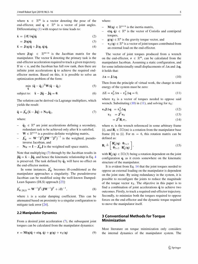
The proposed control method is examined through twodifferent case studies. The first involves a manipulatorlifting and moving a heavy object. Here, the manipulatormust overcome gravitational forces when raising the object,but must also maintain a controlled descent when loweringit (Fig. 1). Additionally, the object is inertially coupledwith the manipulator and dynamic forces must be accountedfor while moving. The second scenario involves robotichigh-pressure blasting where the nozzle reaction forcescontinually push back against the manipulator. Furthermore,the direction of these forces changes depending on wherethe nozzle points as required by the task (Fig. 5).
6.1 Case Study 1: TorqueMinimization for HeavyLifting
Outline In this first case study, a dynamic model of theSawyer robot by Rethink Robotics with 7DOF is simulated.
Fig. 1 When lifting, the manipulator must generate a force oppositethe payload’s gravitational force
J Intell Robot Syst (2019) 96:3–16 9
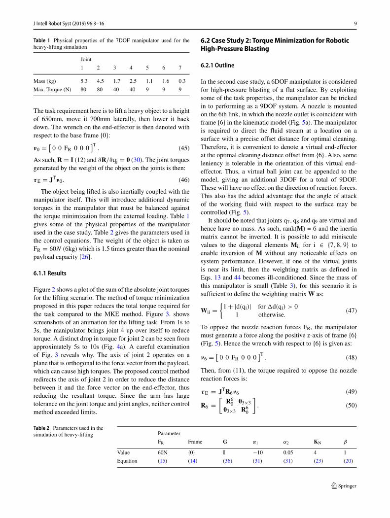
Table 1 Physical properties of the 7DOF manipulator used for theheavy-lifting simulation
Joint
1 2 3 4 5 6 7
Mass (kg) 5.3 4.5 1.7 2.5 1.1 1.6 0.3
Max. Torque (N) 80 80 40 40 9 9 9
The task requirement here is to lift a heavy object to a heightof 650mm, move it 700mm laterally, then lower it backdown. The wrench on the end-effector is then denoted withrespect to the base frame {0}:ν0 = [
0 0 FR 0 0 0]T
. (45)
As such,R = I (12) and ∂R/∂qj = 0 (30). The joint torquesgenerated by the weight of the object on the joints is then:
τE = JTν0. (46)
The object being lifted is also inertially coupled with themanipulator itself. This will introduce additional dynamictorques in the manipulator that must be balanced againstthe torque minimization from the external loading. Table 1gives some of the physical properties of the manipulatorused in the case study. Table 2 gives the parameters used inthe control equations. The weight of the object is taken asFR = 60N (6kg) which is 1.5 times greater than the nominalpayload capacity [26].
6.1.1 Results
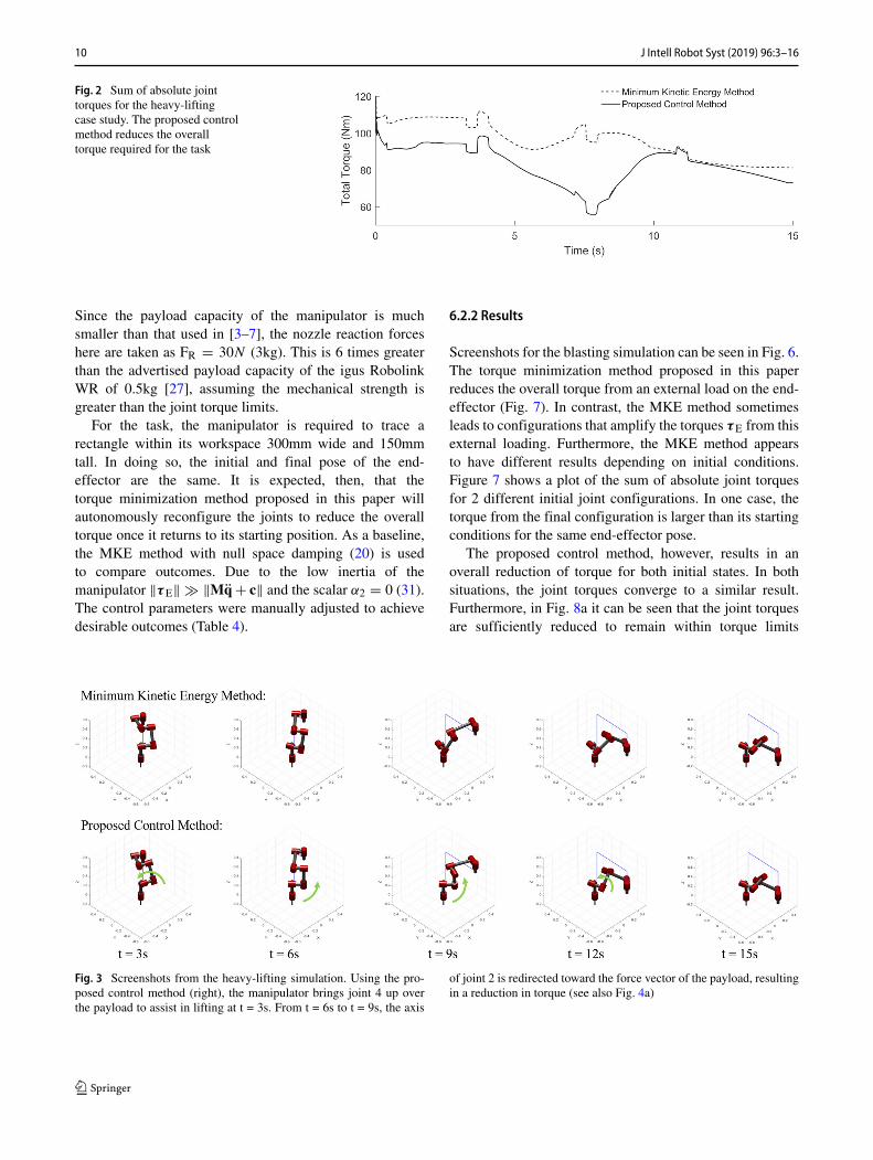
Figure 2 shows a plot of the sum of the absolute joint torquesfor the lifting scenario. The method of torque minimizationproposed in this paper reduces the total torque required forthe task compared to the MKE method. Figure 3. showsscreenshots of an animation for the lifting task. From 1s to3s, the manipulator brings joint 4 up over itself to reducetorque. A distinct drop in torque for joint 2 can be seen fromapproximately 5s to 10s (Fig. 4a). A careful examinationof Fig. 3 reveals why. The axis of joint 2 operates on aplane that is orthogonal to the force vector from the payload,which can cause high torques. The proposed control methodredirects the axis of joint 2 in order to reduce the distancebetween it and the force vector on the end-effector, thusreducing the resultant torque. Since the arm has largetolerance on the joint torque and joint angles, neither controlmethod exceeded limits.
6.2 Case Study 2: TorqueMinimization for RoboticHigh-Pressure Blasting
6.2.1 Outline
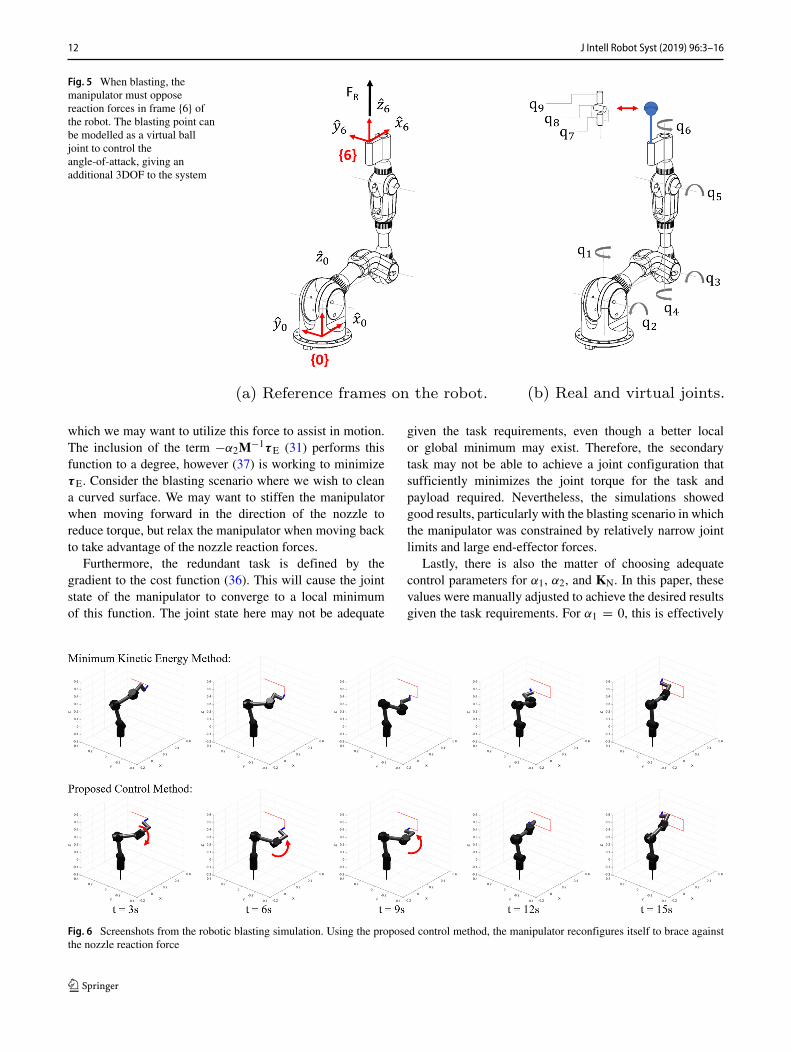
In the second case study, a 6DOF manipulator is consideredfor high-pressure blasting of a flat surface. By exploitingsome of the task properties, the manipulator can be trickedin to performing as a 9DOF system. A nozzle is mountedon the 6th link, in which the nozzle outlet is coincident withframe {6} in the kinematic model (Fig. 5a). The manipulatoris required to direct the fluid stream at a location on asurface with a precise offset distance for optimal cleaning.Therefore, it is convenient to denote a virtual end-effectorat the optimal cleaning distance offset from {6}. Also, someleniency is tolerable in the orientation of this virtual end-effector. Thus, a virtual ball joint can be appended to themodel, giving an additional 3DOF for a total of 9DOF.These will have no effect on the direction of reaction forces.This also has the added advantage that the angle of attackof the working fluid with respect to the surface may becontrolled (Fig. 5).
It should be noted that joints q7, q8 and q9 are virtual andhence have no mass. As such, rank(M) = 6 and the inertiamatrix cannot be inverted. It is possible to add minisculevalues to the diagonal elements Mii for i ∈ {7, 8, 9} toenable inversion of M without any noticeable effects onsystem performance. However, if one of the virtual jointsis near its limit, then the weighting matrix as defined inEqs. 13 and 44 becomes ill-conditioned. Since the mass ofthis manipulator is small (Table 3), for this scenario it issufficient to define the weighting matrixW as:
Wii ={1 + |d(qi)| for �d(qi) > 0
1 otherwise.(47)
To oppose the nozzle reaction forces FR, the manipulatormust generate a force along the positive z-axis of frame {6}(Fig. 5). Hence the wrench with respect to {6} is given as:
ν6 = [0 0 FR 0 0 0
]T. (48)
Then, from (11), the torque required to oppose the nozzlereaction forces is:
τE = JTR6ν6 (49)
R6 =[
R60 03×3
03×3 R60
]. (50)
Table 2 Parameters used in thesimulation of heavy-lifting Parameter
FR Frame G α1 α2 KN β
Value 60N {0} I −10 0.05 4 1
Equation (15) (14) (36) (31) (31) (23) (20)
10 J Intell Robot Syst (2019) 96:3–16
Fig. 2 Sum of absolute jointtorques for the heavy-liftingcase study. The proposed controlmethod reduces the overalltorque required for the task
Since the payload capacity of the manipulator is muchsmaller than that used in [3–7], the nozzle reaction forceshere are taken as FR = 30N (3kg). This is 6 times greaterthan the advertised payload capacity of the igus RobolinkWR of 0.5kg [27], assuming the mechanical strength isgreater than the joint torque limits.
For the task, the manipulator is required to trace arectangle within its workspace 300mm wide and 150mmtall. In doing so, the initial and final pose of the end-effector are the same. It is expected, then, that thetorque minimization method proposed in this paper willautonomously reconfigure the joints to reduce the overalltorque once it returns to its starting position. As a baseline,the MKE method with null space damping (20) is usedto compare outcomes. Due to the low inertia of themanipulator ‖τE‖ ‖Mq+ c‖ and the scalar α2 = 0 (31).The control parameters were manually adjusted to achievedesirable outcomes (Table 4).
6.2.2 Results
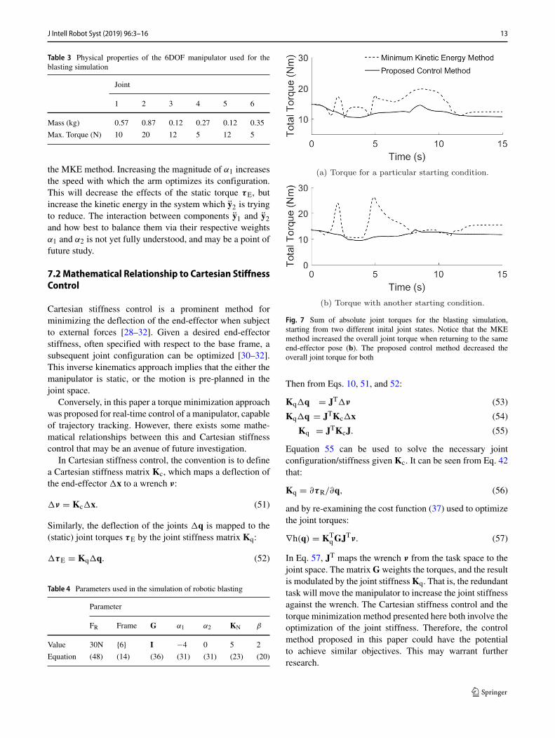
Screenshots for the blasting simulation can be seen in Fig. 6.The torque minimization method proposed in this paperreduces the overall torque from an external load on the end-effector (Fig. 7). In contrast, the MKE method sometimesleads to configurations that amplify the torques τE from thisexternal loading. Furthermore, the MKE method appearsto have different results depending on initial conditions.Figure 7 shows a plot of the sum of absolute joint torquesfor 2 different initial joint configurations. In one case, thetorque from the final configuration is larger than its startingconditions for the same end-effector pose.
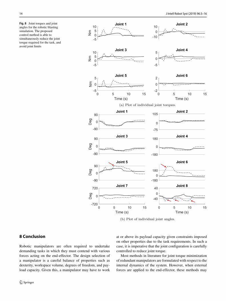
The proposed control method, however, results in anoverall reduction of torque for both initial states. In bothsituations, the joint torques converge to a similar result.Furthermore, in Fig. 8a it can be seen that the joint torquesare sufficiently reduced to remain within torque limits
Fig. 3 Screenshots from the heavy-lifting simulation. Using the pro-posed control method (right), the manipulator brings joint 4 up overthe payload to assist in lifting at t = 3s. From t = 6s to t = 9s, the axis
of joint 2 is redirected toward the force vector of the payload, resultingin a reduction in torque (see also Fig. 4a)
J Intell Robot Syst (2019) 96:3–16 11
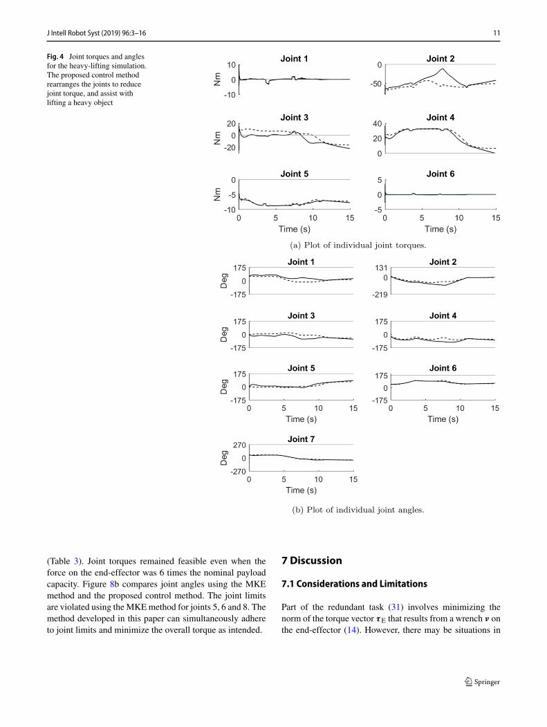
Fig. 4 Joint torques and anglesfor the heavy-lifting simulation.The proposed control methodrearranges the joints to reducejoint torque, and assist withlifting a heavy object
(Table 3). Joint torques remained feasible even when theforce on the end-effector was 6 times the nominal payloadcapacity. Figure 8b compares joint angles using the MKEmethod and the proposed control method. The joint limitsare violated using theMKEmethod for joints 5, 6 and 8. Themethod developed in this paper can simultaneously adhereto joint limits and minimize the overall torque as intended.
7 Discussion
7.1 Considerations and Limitations
Part of the redundant task (31) involves minimizing thenorm of the torque vector τE that results from a wrench ν onthe end-effector (14). However, there may be situations in
12 J Intell Robot Syst (2019) 96:3–16
Fig. 5 When blasting, themanipulator must opposereaction forces in frame {6} ofthe robot. The blasting point canbe modelled as a virtual balljoint to control theangle-of-attack, giving anadditional 3DOF to the system
which we may want to utilize this force to assist in motion.The inclusion of the term −α2M−1τE (31) performs thisfunction to a degree, however (37) is working to minimizeτE. Consider the blasting scenario where we wish to cleana curved surface. We may want to stiffen the manipulatorwhen moving forward in the direction of the nozzle toreduce torque, but relax the manipulator when moving backto take advantage of the nozzle reaction forces.
Furthermore, the redundant task is defined by thegradient to the cost function (36). This will cause the jointstate of the manipulator to converge to a local minimumof this function. The joint state here may not be adequate
given the task requirements, even though a better localor global minimum may exist. Therefore, the secondarytask may not be able to achieve a joint configuration thatsufficiently minimizes the joint torque for the task andpayload required. Nevertheless, the simulations showedgood results, particularly with the blasting scenario in whichthe manipulator was constrained by relatively narrow jointlimits and large end-effector forces.
Lastly, there is also the matter of choosing adequatecontrol parameters for α1, α2, and KN. In this paper, thesevalues were manually adjusted to achieve the desired resultsgiven the task requirements. For α1 = 0, this is effectively
Fig. 6 Screenshots from the robotic blasting simulation. Using the proposed control method, the manipulator reconfigures itself to brace againstthe nozzle reaction force
J Intell Robot Syst (2019) 96:3–16 13
Table 3 Physical properties of the 6DOF manipulator used for theblasting simulation
Joint
1 2 3 4 5 6
Mass (kg) 0.57 0.87 0.12 0.27 0.12 0.35
Max. Torque (N) 10 20 12 5 12 5
the MKE method. Increasing the magnitude of α1 increasesthe speed with which the arm optimizes its configuration.This will decrease the effects of the static torque τE, butincrease the kinetic energy in the system which y2 is tryingto reduce. The interaction between components y1 and y2and how best to balance them via their respective weightsα1 and α2 is not yet fully understood, and may be a point offuture study.
7.2 Mathematical Relationship to Cartesian StiffnessControl
Cartesian stiffness control is a prominent method forminimizing the deflection of the end-effector when subjectto external forces [28–32]. Given a desired end-effectorstiffness, often specified with respect to the base frame, asubsequent joint configuration can be optimized [30–32].This inverse kinematics approach implies that the either themanipulator is static, or the motion is pre-planned in thejoint space.
Conversely, in this paper a torque minimization approachwas proposed for real-time control of a manipulator, capableof trajectory tracking. However, there exists some mathe-matical relationships between this and Cartesian stiffnesscontrol that may be an avenue of future investigation.
In Cartesian stiffness control, the convention is to definea Cartesian stiffness matrix Kc, which maps a deflection ofthe end-effector �x to a wrench ν:
�ν = Kc�x. (51)
Similarly, the deflection of the joints �q is mapped to the(static) joint torques τE by the joint stiffness matrix Kq:
�τE = Kq�q. (52)
Table 4 Parameters used in the simulation of robotic blasting
Parameter
FR Frame G α1 α2 KN β
Value 30N {6} I −4 0 5 2
Equation (48) (14) (36) (31) (31) (23) (20)
Fig. 7 Sum of absolute joint torques for the blasting simulation,starting from two different inital joint states. Notice that the MKEmethod increased the overall joint torque when returning to the sameend-effector pose (b). The proposed control method decreased theoverall joint torque for both
Then from Eqs. 10, 51, and 52:
Kq�q = JT�ν (53)
Kq�q = JTKc�x (54)
Kq = JTKcJ. (55)
Equation 55 can be used to solve the necessary jointconfiguration/stiffness given Kc. It can be seen from Eq. 42that:
Kq = ∂τR/∂q, (56)
and by re-examining the cost function (37) used to optimizethe joint torques:
∇h(q) = KTqGJTν. (57)
In Eq. 57, JT maps the wrench ν from the task space to thejoint space. The matrixGweights the torques, and the resultis modulated by the joint stiffnessKq. That is, the redundanttask will move the manipulator to increase the joint stiffnessagainst the wrench. The Cartesian stiffness control and thetorque minimization method presented here both involve theoptimization of the joint stiffness. Therefore, the controlmethod proposed in this paper could have the potentialto achieve similar objectives. This may warrant furtherresearch.
14 J Intell Robot Syst (2019) 96:3–16
Fig. 8 Joint torques and jointangles for the robotic blastingsimulation. The proposedcontrol method is able tosimultaneously reduce the jointtorque required for the task, andavoid joint limits
8 Conclusion
Robotic manipulators are often required to undertakedemanding tasks in which they must contend with variousforces acting on the end-effector. The design selection ofa manipulator is a careful balance of properties such asdexterity, workspace volume, degrees of freedom, and pay-load capacity. Given this, a manipulator may have to work
at or above its payload capacity given constraints imposedon other properties due to the task requirements. In such acase, it is imperative that the joint configuration is carefullycontrolled to reduce joint torque.
Most methods in literature for joint torque minimizationof redundant manipulators are formulated with respect to theinternal dynamics of the system. However, when externalforces are applied to the end-effector, these methods may
J Intell Robot Syst (2019) 96:3–16 15
increase the overall joint torque. To address this issue, amethod was proposed in this paper to minimize the overalljoint torque where an external loading on the end-effectormust be accounted for. This was applied through nullspace control, such that the joints can autonomouslyrearrange themselves and reduce the effects of the externalforce without affecting the end-effector. Furthermore, theproposed method factors in weighting on the joint motionwhich can be used to incorporate physical constraints on thesolution.
Two case studies were considered to verify the proposedcontrol method. In the first scenario, a manipulator wassimulated lifting and moving a heavy object. In the secondcase study, a manipulator was simulated performing high-pressure blasting, where fluid reaction forces push back onthe end-effector. Using the proposed control method, theoverall joint torques were reduced compared to conventionalmethods. Furthermore, there is the added potential that amanipulator may work beyond its nominal payload capacityusing this control method.
Acknowledgements Research supported in part by the AustralianResearch Council (ARC) Linkage Project (LP150100935) and theRoads and Maritime Services NSW.
Open Access This article is distributed under the terms of theCreative Commons Attribution 4.0 International License (http://creativecommons.org/licenses/by/4.0/), which permits unrestricteduse, distribution, and reproduction in any medium, provided you giveappropriate credit to the original author(s) and the source, provide alink to the Creative Commons license, and indicate if changes weremade.
Publisher’s Note Springer Nature remains neutral with regard tojurisdictional claims in published maps and institutional affiliations.
References
1. Bhangale, P., Agrawal, V., Saha, S.: Attribute based specification,comparison and selection of a robot. Proceedings of the 11thNational Conference on Machines and Mechanisms, pp. 131–138(2003)
2. Yoshikawa, T.: Analysis and control of robot manipulatorswith redundancy. Robotics Research: The First InternationalSymposium, Cambridge, pp. 735–747 (1984)
3. Liu, D.K., Dissayanake, G., Manamperi, P., Brooks, P., Paul,G., Webb, S., Kirchner, N., Chotiprayanakul, P., Kwok, N.M.,Ren, T.: A robotic system for steel bridge maintenance: Researchchallenges and system design, Proceedings of the AustralasianConference on Robotics and Automation (ACRA) (2008)
4. Denso Wave Incorporated, 6-Axis robots VM series specifications(Online), (http://www.denso-wave.com/en/robot/product/five-six/vm Spec.html) Accessed 12th Feb 2018
5. Paul, G., Webb, S.S., Liu, D., Dissanayake, G.: A robotic systemfor steel bridge maintenance: Field testing, Proceedings of theAustralasian Conference on Robotics and Automation (ACRA)(2010)
6. Manamperi, P., Brooke, P., Kaluarachchi, W., Peters, G., Ho,A., Lie, S., To, A., Payl, G., Rushton-Smith, D., Webb, S., Liu,D.K.: Robotic Grit-blasting: Engineering Challenges. SustainableBridges: The Thread of Society, pp. 321–330 (2011)
7. Liu, D.K., Dissanayake, G., Miro, J., Waldron, K.: Infrastructurerobotics: Research challenges and opportunities. Int. Symp.Autom. Robot. Constr. 31, 1 (2014)
8. Kirchner, N., Paul, G., Liu, D.K.: Bridge maintenance robotic arm:mechanical technique to reduce the nozzle force of a sandblastingrig. J. Wuhan Univ. Technol. 28(Suppl. 2006-083), 12–18 (2006)
9. Woolfrey, J., Liu, D.K., Carmichael, M.: Kinematic control ofan autonomous underwater Vehicle-Manipulator system usingautoregressive predictive of vehicle motion and model predic-tive control. IEEE International Conference on Robotics andAutomation (ICRA), pp. 4591–4596 (2016)
10. Hollerbach, J., Suh, K.: Redundancy resolution of manipulatorsthrough torque optimization. IEEE J. Robot. Autom. 3(4), 308–316 (1987)
11. Nedungadi, A., Kazerouinian, K.: A local solution with globalcharacteristics for the joint torque optimization of a redundantmanipulator. Adv. Robot. 6(5), 631–645 (1989)
12. Kang, H., Freeman, R.: Joint torque optimization of redundantmanipulators via the null space damping method. IEEE Inter-national Conference on Robotics and Automation, pp. 520–525(1992)
13. Chung, C., Lee, B., Kim, M., Lee, C.: Torque optimizing controlwith singularity-robustness for kinematically redundant robots. J.Intell. Robot. Syst. 28(3), 231–258 (2000)
14. Tang, W., Wang, J.: Two recurrent neural networks for local jointtorque optimization of kinematically redundant manipulators.IEEE Trans. Syst. Man. Cybern. Part B (Cybern.) 30(1), 120–128(2000)
15. Zhang, Y., Ge, S., Lee, T.: A unified quadratic-programming-based dynamical system approach to joint torque optimization ofphysically constrained redundant manipulators. IEEE Trans. Syst.Man. Cybern. Part B (Cybern.) 34(5), 2126–2132 (2004)
16. Zhang, Y., Guo, D., Ma, S.: Different-level simultaneousminimization of joint-velocity and joint-torque for redundantrobot manipulators. J. Intell. Robot. Syst. 72(3-4), 301–324 (2013)
17. Flacco, F., De Luca, A.: Discrete-time redundancy resolution atthe velocity level with acceleration/torque optimization properties.Robot. Auton. Syst. 70, 191–201 (2015)
18. Bussmann, K., Dietrich, A., Ott, C.: Whole-Body Impedance con-trol for a planetary rover with robotic arm: theory, Control Design,and Experimental Validation. IEEE International Conference onRobotics and Automation (ICRA), pp. 910–917 (2018)
19. Luo, L., Yuan, C., Yan, R.J., Yuan, Q., Wu, J., Shin, K.S.:Trajectory planning for energy minimization of robotic manipula-tors using the lagrange interpolation method. Int. J. Precis. Eng.Manuf. 16(5), 911–917 (2015)
20. Chan, T., Dubey, R.: A weighted least-norm solution basedscheme for avoiding joint limits for redundant joint manipulators.IEEE Trans. Robot. Autom. 11(2), 286–292 (1995)
21. Dariush, B., Hammam, G.B., Orin, D..: Constrained ResolvedAcceleration Control for Humanoid Robots. IEEE/RSJ Interna-tional Conference on Intelligent Robots and Systems, pp. 710–717(2010)
22. Chen, P., Shan, C., Xiang, J., Wei, W.: Moving ObstacleAvoidance for Redundant Manipulator via Weighted Least NormMethod, 27th Chinese Control and Decision Conference (CCDC),pp. 6181–6186 (2015)
23. Wampler, C.: Manipulator inverse kinematic solutions based onvector formulations and Damped-Least-Sqaures methods. IEEETran. Syst. Man. Cybern. SMC-16 1, 93–101 (1986)
16 J Intell Robot Syst (2019) 96:3–16
24. Chiaverini, S., Egeland, O., Kanestrom, R.: Achieving user-defined accuracy with damped least-squares inverse kinematics.Fifth International Conference on Advanced Robotics, pp. 672–677 (1991)
25. Hsu, P., Hauser, J., Sastry, S.: Dynamic control of redundantmanipulators. J. Robot. Syst. 6(2), 133–148 (1989)
26. Rethinkrobotics.com, Sawyer Technical Specifications, (Online)(http://www.rethinkrobotics.com/sawyer/tech-specs/), Accessed5th Feb 2018
27. Igus.com, Robolink WR, (Online), (https://www.igus.com/wpck/16962/N16 10 11) , Accessed 5th Feb 2018
28. Choi, H.R., Chung, W.K., Youm, Y.: Stiffness analysis and controlof redundant manipulators IEEE. International Conference onRobotics and Automation (ICRA), pp. 689–695 (1994)
29. Ang, M.H., Andeen, G.B.: Specifying and achieving passivecompliance based on manipulator structure. IEEE Trans. Robot.Autom. 11(4), 504–515 (1995)
30. Li, Y., Kao, L.: Stiffness control on redundant manipulators: aunique and kinematically consistent solution. IEEE InternationalConference on Robotics and Automation (ICRA), pp. 3956–3961(2004)
31. Ajoudani, A., Tsagarakis, N.G., Bicchi, A., Ajoudani, A.,Tsagarakis, N.G.: Bicchi, On the role of robot configuration inCartesian stiffness control”, IEEE International Conference onRobotics and Automation (ICRA), pp. 1010–1016 (2015)
32. Gasparri, G.M., Gabiani, F., Garabini, M., Pallottino, L., Catalon,M., Grioli, G., Perischin, R., Bicchi, A.: Robust optimization ofsystem compliance for physical interaction in uncertain scenarios.IEEE-RAS 16th International Conference on Humanoid Robots(Humanoids), pp. 911–918 (2016)
Jon Woolfrey received his B.E. in Mechanical and MechatronicEngineering from the University of Technology Sydney (UTS) in2015. He is currently a Doctoral Candidate with UTS, focusing oncontrolling mobile manipulators under disturbance and working withheavy loads. His research interests include control of robotic systems,optimization, statistical modelling, and design. He has helped developmobile robots for infrastructure maintenance and control methods toenable them to operate effectively.
Wenjie Lu received his B.S. in Mechatronic Engineering fromZhejiang University, Hangzhou, China in 2009. He then received hisM.S. and Ph.D. in Mechanical Engineering from Duke University,Durham, NC, USA in 2011 and 2014 respectively. His researchinterests include the learning of efficient motion planners andcontrollers for mobile robots that are subject to uncertainties in 3Dcomplex environment. He has been developing such algorithms viaintegrating machine learning, approximate dynamic programming,hybrid systems, information theories, and nonparametric Bayesianmodels.
Dikai Liu received his Ph.D. degree in 1997. His main research interestis robotics including exploration, motion planning, robot teams, andphysical human-robot interaction. He has been developing novelmethods and algorithms that enable robots to operate in unstructuredand complex 3D environments autonomously or collaboratively withhuman users. Example robotic systems he developed and practicallydeployed include autonomous grit-blasting robots for steel bridgemaintenance, assistive robots for human strength augmentation inindustrial applications and bioinspired climbing robots for steelstructure inspection.