Embed Size (px)
Citation preview
INSTRUMENTATION RESEARCH
Transducer for Interfaces • Paris-Seeley et al.
A Compliance-Independent Pressure Transducer for Biomedical Device-Tissue Interfaces NANCY J. PARiS-SEELEY, MASc PENG, JAM ES A. McEwEN, PHD, PENG, DOUGLAS P. ROMIlLY, PHD, PENG
The measurement of the interface pressure between a biomedical device and part of the human body is useful to improve the perfomlOnce mId safety of such devices dun-ng design. Testing of a selectiml of existing interface pressure transducers has demonstrated that many are dependent on device and tissue compliance. Such a transducer is useful only in an application where it has been calibrated for specific device-tissue compliance combinations. To overcome this limitation, the authors developed an i"terface pressure transducer whose output signal is not
affected by changes in inter/ace compliance. '/1,is enables the trmlsducer to qumltitatively measure pressure in many applicatimls without the "eed to calibrate it for varying compliance conditions. Surgical retraction and surgical tourniquets were selected as demonstration applications fo r the developed transducer. because they represent a wide spectrum of device and tissue cltaracten'stics and properties, and are in common use. BIOMEDICAL INSTRUMENTATION & TECHNOLOGY 2000:34: 423-431.
PEER-REVIEWED RESEARCH
Many biomedical procedures involve the application of pressure from a biomedical device to body tissue. Examples include surgical retractors Ihat apply pressure to
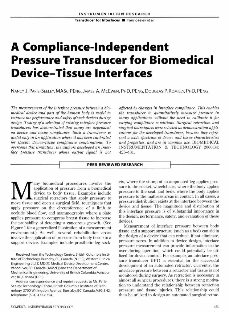
move tissue and open a su rgical field, tourniquets that apply pressure on the circumference of a limb to occlude blood now, and mammography where a plate applies pressure to compress breast tissue to increase the probabilily of detecting a cancerous growth. (See Figure 1 for a generalized illustration of a measurement environment.) As well, several rehabilitation areas involve the application of pressure from body tissue to a support device. Examples include prosthetic leg sock-
Received from the Technology Centre, Brit ish Columbia Institute ofTechnology, Burnaby, BCCanada (NJP-S); Western Clinical Engineering Ltd. & MDDC Medical Device Development Centre. Vancouver, BC Canada (JAMcE); and the Department of Mechanical Engineering. University of British Columbia, Vancouver, BC, Canada (DPR).
Address correspondence and reprint requests to Ms. ParisSeeley:Technology Centre, British Columbia Institute ofTechnology. 3700 Willingdon Avenue, Burnaby, BC, Canada. V5G 3H2; telephone: (604) 432-8754.
BIOMEDICAllNSTRUMENTAnoN & TECHNOlOGY
els, where the stump of an amputated leg applies pressu re to the socket, wheelchairs, where the body applies pressure to the seat. and beds, where the body applies pressure to the mattress areas in contact. In all cases. a pressure distribution exists at the int.erface between the device and tissue. The magnitude and distribution of th is interface pressure is of substantial importance in the design. perfOnllance. safety, and evaluation of these devices.
Measurement of interface pressure between body tissue and a support stmcture (such as a bed) can aid in the design of a device that can red uce, if not eliminate. pressure sores. In addition to device design. interface pressure measurement can provide infonllation to the user during operation. which cou ld poten tially be utilized for device control. For example. an interface pressure transducer OPT) is essential for the successfu l development of an automated retractor. Currently. the interface pressure between a retractor and tissue is not monitored during surgery. As retraction is necessary in almost all surgical procedures, there is a strong motivation to understand the relationship between retraction pressure and tissue injuries. 111is relationship could then be utilized to design an automated surgical retrac-
4ll
IN STR U MENTATI O N RESEARCH
Tran sducer for Interfaces • Paris-Seeley et al.
Device Applied Pressure
~~ }
Interface
Figure 1. Schematic of the interface measurement environment.
tor to reduce, if not eliminate, injuries caused by inappropriate retraction pressures. Furthennore, a humanheld surgical retractor could also benefit from the integration of an IPT. particularly in surgeries involving the retraction of brain or liver, where tissue damage could lead to pennanent debilitating injuries.
As previously mentioned, a tourniquet cuff applies pressure around the circumference of the li mb to stop blood flow past the cuff. Currently. the only indication of interface pressure between the cuff and underlying tissue is the pneumatic pressure in the cuff. However, as the interface pressure has been shown to vary along the width of the cuff, a need exists for an IPT that can quantify this varying interface pressure. The use of IPTs could aid in the design of tourniquet cuffs by helping to achieve the most desirable pressure distribution. Such a transducer. if integrated into a tourniquet cuff system, could also be useful in the clinical application of the cuff by helping to ensure the best fit between the cuff and the limb. Furthennore, the pressure measurement data could be integrated into algorithms that could be developed to warn clinicians of high pressures and long application times. thus mitigating the risk of injury due to tourniquet cuffs.
A general-purpose IPT would need to produce reliable and repealable output in several target applications. However, the compliance and curvature conditions in surgical retraction and tourniquet applications vary widely. In surgical retraction, the retractors are rigid and vary in curvatu re depending on the application. In tourniquets, the cuff varies in curvature and is compliant. In either case, the tissues may vary dramatically in compliance, from being very compliant (i.e., fat) to being very stiff (i.e .. muscle). 1l1erefore, varying compliance and curvature conditions must be addressed when defin ing transducer specifications.
A wide variety of IPTs have been used in the bio-
424
medical and rehabilitation application areas previously mentioned. Unfortunately, results from different types of transducers have been difficult to compare quantitatively. even within a single application area. In addition, no standards currently exist that define the methods to be used in interface pressure measurement. Ii was therefore recognized thai a need exists fo r the development of an interface pressure Iransducer that can be used in several target applications with varying tissue and device compliances such that the result s can be reliably replicated and compared.
Review of Previous Research
A review of tlle available clinical. commercial. and engineering literature identified a wide range of transducers and transducer technologies used for interface pressure measurement in a wide variety of applications. Retractor pressures have been measured in neurologic procedures and. more recently, in a back-muscle study. Kawaguchi et aJ.l described a system used to measure retractor pressure on back muscles employing a strain gauge and a strain meter. Unfortunately, no calibration techniques or transducer performance characte ristics were provided for this work. Several other investigators have used strain gauges mounted in various locations on retractors to relate the strain in the retractor to the applied forces in the brain.z-s The calibration technique employed hanging a known weight from the retractor tip and correlating load-to-strain gauge output. Although thi s technique provides quantitative force results, it does not provide localized pressure information. since a pressure applied to a small area of the retractor cou ld produce the same output as a lower pressure applied to a larger area of the retractor.
Studies have shown that in pneumatic tourniquets. the pressure distribution on the limb varies with distance from the edges of the cuff. 111is was shown by Mclaren et al.6 in experiments measuring the pressure distribution under a standard pneumatic cuff when applied to the hind limbs of anaesthetjzed dogs. A catheter and fluid pressure transducers were embedded in the tissue at various locations to measure the softtissue pressure. Two important limitations exist with this technique for interface pressure measurement: the technique is invasive; the transducer measures hydro. static fluid pressure. Given that soft tissue behaves as a composite semisolid material. the relationship between fluid pressure and soft tissue interface pressure is unclear. In contrast, Breault et aV used a pneumatic transducer with electrical switches to measure tJw pressure of ti ssue underlying a pneumatic cuff in cadavers.
NOV~M8ERlDECEMBER 2000

INSTRUMENTATION RESEARCH
Transducer for Interfaces • Paris-Seeley et al.
Although this technique was used to measure underlying tissue pressures, it could be used for interface pressure measurements as well. However, four of the major limitations of this transducer. as reported by Breault. were:
1. it measured pressure only intenniuentJy; 2. it displayed significant hysteresis; 3. it was unsuited for array measurements; and 4. it was too unreliable for routine clinical use.
The literature also includes applications of inter· face pressure measurement in mammography.8 cushion and mattress applications.9- !8 prosthetic sockets. !9-Z! foot pressure.zz.zs and pressure garments for treatment of bum injuries.Z6-Z7 Unfortunately. throughout thi s work. no standard method of measuring interface pressure was described and , in many cases. investigators cautioned against comparing interface pressure measurements obtained using different measu rement systems.
1lle fo llowing conclusions were reached as a result of a critical review of the literature describing interface pressure transducers used in the above applications:
1. the transducers were used in a single application; 2. the transducers were not evaluated or calibrated
under interface materials of differing compliance; 3. the curvature of some transducers adversely
affected their output; and 4. perturbation of the interface by the transducer
altered the pressure distribution.
As the purpose of the present study was to identify or develop for use in the target applications a generic lIT that is both independent of interface material compliance and suitable for use over a wide range of interface curvatures. none of the reviewed transducer systems was deemed satisfactory.
METHODS
DEVELOPMENT OF OPTIMAL DESIGN SPECIFICATIONS
From the literature review and an examination of the biomedical applications mentioned. optimal design specifications for an IPT were defi ned as follows.
The transducer must
• measure pressure applied by a specified medical device to a body tissue;
• measure pressure in a direction normal to the
BIOMEOICAllNSTRUMENTATlON & TECHNOlOGY
device-tissue interface; • have a sensing elemen t area no greater than 1 cm in
diameter; • measure pressure in the range of 1-500 mmHg; • be capable of being configured in arrays or matrices
as required fo r a given application: • provide output that is independent of the compliance
characteristics of the interface materials: • provide output that is independent of the curvature of
the interface; • be constructed of materials t hat are biocompatible
(incJuding packaging materials): • be resistant to chemicals encountered in target appli·
cations (including packaging mate rials): • be radio-transparent for imaging applications (includ·
ing packaging materials): • measure with maximum error of 1:2 mmHg; • have a maximum hysteresis and/ or drift between
measurements over a I-hour time period of 1:2 mmHg; • provide an adequate measurement data rale for the
defined applications; • fail in a mode that is obvious to the operator and safe
for the patient; • provide temperature compens..'llion over the range of
temperatures found in the target applications. typi· cally between room temperature (- 21°C) and body temperature (-37°C);
• comply with relevant IEC and CSA standards, and ISO manufacturing process Sl'andards;
• not introduce any potential electrical or them131 hazard: • be immune to levels of electromagnetic interference
encountered in target application environments; • be able to withstand sterilization by gamma radiation.
ethylene oxide. or autoclave; • penni! calibration. or calibration-checking, of the
transducer by a cJinicaluser in the target application environment;
• have calibration checking that is fas t. convenient. and intuitive (under 5 minutes):
• if designed to be reusable and intended for integration with instrumentation and long-lenn use, have a cost of manufacture. including signal pre-processing hardware. of less than $50:
• if designed to be a disl>osabie or consumable transducer. intended for integration with ~patienl-applied parts~ that are discarded after a single usage (such as some pneumatic cuffs or retractor blades). and have a cost of manufacture. excluding signal processing hardware, of less than $ 1 .
These optimal design specifications were used to aid in evaluating both existing and developed transducers.
415

INSTRUMENTATION RESEARCH
Transducer for Interfaces • Paris-Seeley et al.
Rubbec membrane -0.25 nun thick
Sealing ring - 5 nun thick
Spbygmomaoomeler
Figure 2. Calibration system designed by Sachs.
Base - 250 nun diameter
Transducer
EVALUATION OF EXISTING INTERFACE PRESSURE TRANSOUCERS
An objective of this research was the development of a suitable calibration system for the evaluation and comparison of a variety of interlace pressure transducers. Ferguson-Pell28 emphasized the critical importance of using a calibration technique that simulated interlace conditions when calibrating an IPT. The calibration system developed for this research was based on a design described by Ferguson-Pell and was adapted and improved to allow testing under interlace materials of varying compliance (Figure 2).
An extensive survey of prototype and commercially
T,Su
IClt condition I
L
Iffl condition :2
teJ( condilion J
ICSI condit ion ~
Flgur.l. Transducer orientations and interface material lay·ups used in the calibration system. L '" latel(; T '" transducer; B II: base plate; U '" urethane; Su '" sensing element up; sci '" sensing element down.
426
available transducers was conducted to detemli ne which transducer technologies had potential for use in the target applications. These were identified as follows:
• Force-sensitive resistive material • Semiconductor capacitor • Fluid-filled pads with remote fluid-pressure measure
ment • Constant pneumatic flow valve • Strain gauge on diaphragm
Nine transducers based on these technologies were then obtained or constructed for evaluation in the cali· bration system.
The transducers were tested under several conditions to quantify the measured relationship between applied pressure and transducer output. hysteresis and drift characteristics. and the effects of having different interlace materials of varying compliance. The basic experimental procedure was to test each transducer between the aluminium base plate and a latex memo brane I mm thick. This was denoted test condition I. Under these conditions. the applied pressure was incrementally increased from 0 to 450 mmHg and held for 15 minutes to assess any drift characteristics. '111e pressure was then incrementally decreased back down to 0 mmllg. At each incremental pressure level. the transducer output was recorded . Transducers that per· fomlcd well under test condition 1 were also tested for their perlonnancc characteristics using other interlace materials. Various transducer orientations and material Jay-ups were used in this subsequen t testing (Figure 3) . llu~ interface materials generally consisted of urethane gels of varying compliance.
A comparison of the results from the nine transduc· ers tested indicated that none was suitable for use in the target applications in their current configurations and packaging (fable 1). However. through the evaluation
NOVEMBERIOECEt.1BER 200J
INSTRUMENTATION RESEARCH
Transducer for Interfaces. Paris-Seeley et al.
Table 1. Comparison of Transducers Tested
Transducers Drift
Uniforce™ y" FSRTM Yes NamTai Intermittent Mikro-tip No Constant pneumatic flow No Steriteke No OMilied No Smaller oil-filled Yes Pneumatic, electrical switch No
of these transducers, an essential characteristic for a compliance-independent interlace pressure transducer became apparent Transducers that operate by relating applied pressure to the deflection of their sensing element are highly dependent on the compliance of the interlace material. As such, in theory, lithe deflection of the sensing element could be minimized, the compliance dependence would also be minimized. Subsequent transducer development utilized this idea in the conceptualization of a new prototype device.
DEVELOPMENT OF A NOVEL INTERFACE PRESSURE TRANSDUCER
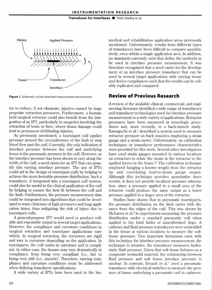
The developed transducer is based on a transducer that has a diaphragm as its sensing element The underlying principle of the developed transducer is as follows. A transducer that senses pressure (i.e., the nonnal component of force) by the amount of deflection of its diaphragm will be highly dependent on the stress-strain or compliance characteristics of the interface material. If the interlace material is very compliant (Le., fat), it will confonn to the diaphragm much like a fluid, and the contact interlace pressure will more closely represent applied pressure (high-compliance material (HeM) in Figure 4). However, if the interlace material is rigid (Le., muscle), it will be unable to confonn to the diaphragm. In this case, the pressure will be shed from the diaphragm to the solid material around the diaphragm that will develop stresses until it has reached a state of equilibrium. If this occurs. the diaphragm deflection will not correlate well to the applied pressure (1ow-compliance material (LCM) in Figure 4). A method of minimizing the deflection of the sensing element of a transducer. while maintaining a method of measuring the interlace pressure, is to apply fluid pressure to the bottom of the diaphragm. Theoret-
BIOMEDICAL INSTRUMENTATION & TECHNOlOGY
Compliance-. Curvature-. Hysteresis Dependent Dependent
y" N/A Yes Yes N/A Yes Yes Yes N/A No Yes N/A No Yes N/A No Yes N/A No Yes N/A Yes N/A N/A No Yes N/A
ically, without the presence of any shear. bending. or torsional force (i.e., pressure is distributed unifonnly). the interlace pressure applied to the diaphragm would be indicated by the amount of fluid pressure required to maintain the diaphragm in its original position. Although in practice the applied interface pressure may not be unifonnly distributed. the resultant effect could be minimized by employing a small-diameter diaphragm (Le., recall that the specifications state that the transducer sensing area must be less than or equal to 10 mm in diameter).
The developed transducer operates by balancing interlace pressure on the diaphragm with an equal and opposite fluid pressure. The fluid pressure can be measured using any number of effective inexpensive fluid· pressure transducers. The fluid pressure is theoretically equivalent to the applied interface pressure if the diaphragm is returned to its original, unloaded position. The opposing fluid pressure will average the applied interface pressure over the area of the diaphragm.
Many methods could be employed to measure the position of the diaphragm to detennine when it has returned to its original position. Examples include measuring the capacitance between the diaphragm and a base plate. the current through an electrical contact.
Applied I' ressure
ilil1wm1Uill.J '--Will III 11111111
mw~r;Wfllr\( 1~H;t;~tj~} Load Transfer Through Mllteri:l lio Tr:ulSulicer
Figure 4. Load transfer through material 10 transducer.
427
INST R UMENTATION RESEARCH
Transducer for Interfaces . Paris-Seeley et at
A
B
+ "-_ __ 0 v",
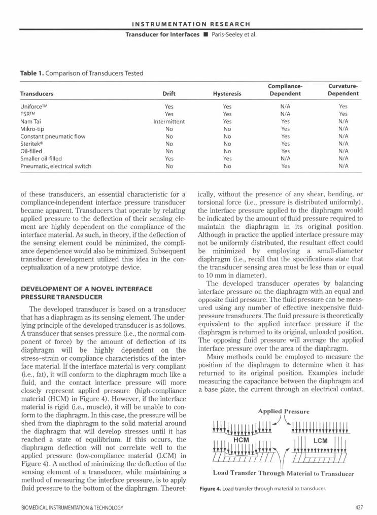
Figurl S . Wheatstone bridge circuit.
Figurl 6. Schematic of the fourth-generation transducer design (in millimeters).
the intensity of light bouncing off the diaphragm using fiberoptics, or the amount of strain in a strain gauge mounted to the diaphragm. To test the concept. a si mple strain-gauged diaphragm is employed here to
measure the position of the diaphragm. To measure the point of zero deOection . a single
strain gauge is mounted to the diaphragm and utilized as a single ann in a balanced Wheatstone bridge circuit (Figure 5). When the diaphragm deOects. the resistance in the strain gauge changes. which unbalances the bridge and causes a voltage output. 1l1is principle can be utilized to determine when the diaphragm is returned to its original posit.ion by monitori ng when the voltage output from the bridge returns 10 zero.
The instrumentation required to operate the transducer includes an air source and a pressure-sensing device to pressurize and measure the chamber pressure, and a voltmeter to measure the Wheatstonebridge voltage output. The chamber pressure was con· trolled manually, but hardware and software could be developed to autoregulate this function.
Several generations of transducers were manufactured and evaluated, each generation trying to improve upon the one before. The fourth-generation prototype was constructed as follows (Figure 6). hs base geometry was 24 mm in diameter x 3 mm in depth. The base material was stainless st.eel. 1lle diaphragm was made of Mylar film. The strai n gauge was bonded to the underside of the diaphragm. An ultrasonic gel was used to reduce shear stresses on the diaphragm.
Results and Discussion
EVALUATION OF THE DEVELOPED TRANSDUCER IN THE CALIBRATION SYSTEM AND DEMONSTRATION APPLICATIONS
TIle fo urth-generation interface-pressure transducer
--0- lest condition I -- test condition 2 --0- tCSl condition 2 (stiffer gd )
500 45.
" 400 :r E 35. E ~
300 w -~ 250
• 200 ~
~ 15. 6 100
5 •
• • ,.
428
100 t ~o '00 :!so 300
Applied Pressure (mmHg)
350 400 45.
Figure 7 . Measured rel~tionship between the applied pressure and the output from the fourth ·generation steel transducer prototype with liquid gel and ~Iurninum ~hirn . The three conditions tested resulted in the !-arne output (i.e, all three lines are on top of one another).
NOVEMBERIDECEMBER 2000
INSTRUMENTATION RESEARCH
Transducer for Interfaces • Paris-Seeley et al.
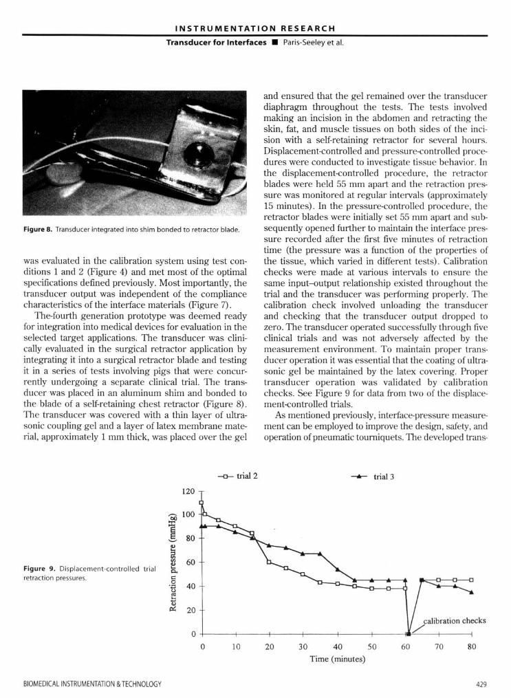
Figure 8. Transducer integrated into shim bonded to retractor blade.
was evaluated in the calibration system using test conditions 1 and 2 (Figure 4) and met most of the optimal specifications defined previously. Most importantly, the transducer output was independent of the compliance characteristics of the interface materials (Figure 7).
The-fourth generation prototype was deemed ready for integration into medical devices for evaluation in the selected target applications. The transducer was clinically evaluated in the surgical retractor application by integrating it into a surgical retractor blade and testing it in a series of tests involving pigs that were concurrently undergoing a separate clinical trial. The transducer was placed in an aluminum shim and bonded to the blade of a self-retaining chest retractor (Figure 8) . lne transducer was covered with a thin layer of ultrasonic coupling gel and a layer of latex membrane material, approximately 1 mm thick, was placed over the gel
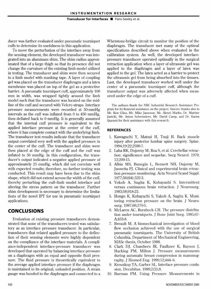
Figure 9. Displacement-contro lled trial retra(!ion pressures.
120
--0- trial 2
and ensured that the gel remained over the transducer diaphragm th roughout the tests. 1lle tests involved making an incision in the abdomen and retract ing the skin, fat, and muscle tissues on both sides of the incision with a self-retaining retractor for several hours. Displacement-controlled and pressure-controlled procedures were conducted to investigate tissue behavior. In the displacement-controlled procedure, the retractor blades were held 55 mm apart and the retraction pressure was monitored at regular intervals (approximately 15 minutes). In the pressure-controlled procedure, the retractor blades were initially set 55 mm apart and subsequently opened further to maintain the interface pressure recorded after the first five minutes of retraction time (the pressure was a function of the properties of the tissue, which varied in different tests). Calibration checks were made at various intervals to ensure the same input-output relationship existed throughout the trial and the transducer was performing properly. 11le calibration check involved unloading the transducer and checking that the transducer outpu t dropped to zero. The transducer operated successfully through five clinical trials and was not adversely affected by the measurement environment. To maintain proper transducer operation it was essential that the coating of ultrasonic gel be maintained by the latex covering. Proper transducer operation was validated by calibration checks. See Figure 9 for data from two of the displacement-controlled trials.
As mentioned previously, interface-pressure measurement can be employed to improve the design. safety, and operation of pneumatic toumiquets. TIle developed trans-
--6-- trial 3
calibration checks
o +---~---+----~--~---+--~,,/,~-+----o 10 20 30 40 50 60 70 80
Time (minutes)
BIOMEOI(Al INSTRUMfNTATION & TECHNOlOGY 429
INSTRUMENTATION RESEARCH
Transducer for Interfaces • Paris-Seeley et aL
ducer was further evaluated under pneumatic tourniquet cuffs to determine its usefulness in this application.
To move the perturbation of the interface away from the sensing element. the developed transducer was integrated into an aluminum shim. The shim radius approx· imated that of a large thigh so that its presence did not change the curvature of the existing limb model utilized in testing. The transducer and shim were then secured to a limb model with masking tape. A layer of coupling gel was placed on the transducer diaphragm and a latex membrane was placed on top of the gel as a protective barrier. A pneumatic tourniquet cuff, approximately 100 mm in width, was wrapped tightly around the limb model such that the transducer was located on the midline of the cuff and secured with Velcro straps. Interface pressure measurements were recorded at 50-mmHg intervals as the cuff was inflated from 0 to 450 mmHg, then deflated back to 0 mmHg. It is generally assumed that the internal cuff pressure is equivalent to the applied interface pressure at the center of the cuff, where it has complete contact with the underlying limb. The transducer test results indicate that the transducer output correlated very well with the applied pressure in the center of the cuff. Tbe transducer and shim were then placed at the edge of the cuff and the cuff was inflated to 50 mmHg. In this configuration , the transducer's output indicated a negative applied pressure of approximately 25 mmHg, which did not correlate well wilh expected results; therefore, no further testing was conducted. Tbis result may have been due to the shim shape, which did not extend across the width of the cuff, thereby perturbing the cuff-limb model interface and altering the stress pattem on the transducer. Further shim development is necessary to determine the limita· tions of the novel IPT for use in pneumatic tourniquet applications.
CONCLUSIONS
Evaluation of existing pressure transducers demonstrated that none of the transducers tested was satisfactory as an interface pressure transducer. In particular. transducers that related applied pressure to the deflection of their sensing elements were highly dependent on the compliance of the interface materials. A compliance-independent interface-pressure transducer was developed that operated by balancing interface pressure on a diaphragm with an equal and opposite fluid pressure. The fluid pressure is theoretically equivalent to the average applied interface pressure if the diaphragm is maintained in its original. unloaded position. A strain gauge was bonded to the diaphragm and connected to a
430
Whetstone-bridge circuit to monitor the position of the diaphragm. The transducer met many of the optimal specifications described above when evaluated in the calibration system. As well, the developed interfacepressure transducer operated optimally in the surgical retraction application when a layer of ultrasonic gel was applied to the diaphragm and a layer of latex was applied to the gel. The latex acted as a barrier to protect the ultrasonic gel from being absorbed into the tissues. Last. the developed transducer worked well under the center of a pneumatic tourniquet cuff, although the transducer output was adversely affected when measured under the edge of a cuff.
The authors thank the NRC Industrial Research Assistance Program for its financial assistance on the project. Sincere thanks also to Mr. Ken Glinz, Mr. Mike Jameson, Mr. Alexei Marko. Dr. Martine Janicki, Mr. Anton Schrcinders, Mr. David Camp. and Dr. Karim Qayumi for their assistance with this research.
REFERENCES
1. Kawaguchi Y, Matsui H, Tsuji H. Back muscle injury after posterior lumbar spine surgery. Spine. 1994;19:22;259(). 7.
2. Laha RK, Dujovny M, Roa S, et al. Cerebellar retraction: significance and sequelae. Surg Neurol. 1979; 12:209-15.
3. A1bin MS, Bunegin L, Bennett NH. Dujovny M, Jannetta PJ Clinical and experimental brain retraction pressure monitoring. Acta Neurol Scand Suppl. 1977;56(64) ;522-3.
4. Yokoh A. Sugita K, Kobayashi S. Intermitt ent versus continuous brain retraction. J Neurosurg. 1983;58;918-23.
5. Hongo K, Kobayachi S, Yakoh A, Sugita K Monitoring retraction pressure on the brain. J Neurasurg. 1987;66;270-5.
6. Mclaren AC, Rorabeck CH. The pressure distribu· tion under tourniquets. J Bone Joint Surg. 1985;67-A;433-8_
7. Breault M. A biomechanical investigation of blood flow occlusion achieved with the use of surgical pneumatic tourniquets. 111e Universi ty of Bri tish Columbia, Department of Mechanical Engineering. MASc thesis. October 1988.
8. Clark DJ. Chambers fR. Faulkner K Rayson J. Hacking PM, Milton J. Pressure measurement'S during automatic breast compression in mammography. J Biomed Eng. 1990; 12;444-6.
9. Krouskop TA, Garber SI- Interface pressure confusion. Decubitus. 1989;2(3):8.
10. Burman PM. Using Pressure Measurements 10
NOVEMBERIDECEMBER 2000
INSTR U MENTATION RESEAR C H
Transducer for Interfaces • Paris-Seeley et al.
Evaluate Different Technologies. Decubitus. 1993; 6(3);3842.
11 . Clark M, Rowland LB. Comparison of contact pressures measured at the sacrum of young and elderly subjects. 1 Biomed Eng. 1989; 11 (3);197-9.
12. Hover AE, Krouskop TA Pressure relief characteristics of a new foam overlay: a preliminary perfonnance evaluation. 1 ET Nurs. 1992: 19(2);42-7.
13. Petrie LA, Hummel RS 3d. A study of interface pressure fo r pressure reduction and relief mattresses. J Enterostom Ther. 1990;17(5);2 12-6.
14. Cron L, Sprigle S. Clin ical evaluation of the hemiwheelchair cushion. Am 1 Occup Ther. 1993;47:141-4.
15. Reidel SA, Harris GF, DeRosia lJ , et al. An instrumented chair for assessing seated stability. 1 Clin Eng. 1990;15:6.
16. Thompson-BishopJY, Mottola CM. 1issue interface pressure and estimated subcutaneous pressures of 11 different pressure-reducing support surfaces. Decubitis. 1992;5(2);42-6.48.
17. Eckrich KM. A pneumatic bladder array for measuring dynamic interface pressure between seated users and their wheelchairs. Copyright lSA 1991-Paper #91-{)18.0067-8856/91/135-140/So+.5Opp.
18. Patel A, Kothari M, Webster l G, Tompltins WJ, Wert.sch 11. A capacitance pressure sensor using a phase-locked loop. J Rehabil Res Devel. 1989; 26:(2);55--62.
19. Appoldl FA, Bennett L, Contini R. Socket pressure as a function of pressure transducer protrusion. Bull Prosthetics Res. 1969;10:231H9.
BIOMEDlCAllNSTRUMENTAOON & TECHNOlOGY
20. Rae JW, Cockrell JL Interlace pressure and stress distribution in prosthetic fi lling. Bull Prosthetics Res. 1971;10(16) :64-111.
21. Van Pijkeren T, Naeff M. Hok Kwee H. A new method for the measuremenl of nonnal pressure between amputation residual limb and socket. Bull Prosthetics Res. 1980;10(13);31-4.
22. Zhu H, Harris GF, Wertsch Jl , Tompkins WJ. Webster JG. A microprocessor-based data-acquisition system for measuring plantar pressures from ambulatory subjects. IEEE Trans Biomed Eng. 199 1; 38:710-4.
23. Hennig EM, Cavanagh PRo A1bert HT, Macmillan NH. A piezoelectric method of measuri ng the vertical contact stress beneath the human foot. J Biomed Eng. 1982;4:213-22.
24. Lord M, Reynolds D, Hughes j. Foot pressure measurement: a review of cl in ical fi ndings. J Biomed Eng. 1986;8:283-94.
25. Roy JK Force, pressure, and motion measurements in the foot: current concepts. Clin Podiatr Med Surg. 1988;5:491-508.
26. Harries CA, Pegg SP. Measuring pressure under bums pressure gannents using the Oxford pressure monitor. Bums. 1989; 15: 187-9.
27. Barbenel JC, Sockalingham S. Device for measuring soft tissue interlace pressures. J Biomed Eng. 1990;12:519-22.
28. Ferguson-Pell PM. Design criteria fo r the measurement of pressure at body/ support inlerfaces. Engineering in Medicine. 1980:9:209-14.
4J1


![[Compliance Presentation Title/Subject] · function. Compliance Testing is the independent testing arm of the Citi Compliance function. Our mission is to: Compliance Testing plans](https://img.dokumen.tips/doc/110x75/5e47b61e9e5ff6667e3cd0eb/compliance-presentation-titlesubject-function-compliance-testing-is-the-independent.jpg)