Embed Size (px)
Citation preview

A Comparative Study on the Effects of Internal VS External
Pressure for a Pressure Vessel subjected to Piping Loads at
the Shell-to-Nozzle Junction
Ashveer Maharaj
University ofKwaZulu-Natal
Durban
This thesis is submitted in fulfillment of the academic requirements for the Degree of Master of
Science in Engineering in the School of Mechanical Engineering, University of Natal.
November 2003
Supervisors :
Professor S. Adali
Dr. C. 1. von Klemperer
As the candidate's supervisors we havelhave not approved this thesis/dissertation for
submission
Signed: ... . . .... .. ... ... . .... . .... .. . Name : .... . ... .. . . .......... .. ... .. . Date : .. .... ..... .. ...... .. ...... .
Signed: . .. ..... . . .. . ...... .. ... '" ... Name : .... .. . .. ' " .. ... .. . . .. .. ... . . Date : ...... ... . .. .. . .. ... . ..... ..

Acknowledgments
I would like to thank my supervisors Professor S. Adali and Dr. C. J. von Klemperer for their
assistance and guidance.
I gratefully acknowledge the assistance given to me by my mentor from SASOL, Mr. Daniel
Francis.
I would especially like to thank Mr. John Fogg, of Elgin Engineering, for his help in several
aspects of this study.
I would like to thank SASOL Ltd. for a research sponsorship in undertaking this investigation
on their behalf.
11

ABSTRACT
This investigation seeks to perform a comparative study between the combined effects of
internal pressure and piping loads versus external pressure and piping loads on a pressure
vessel. There are currently several well-known and widely-used procedures for predicting the
stress situation and the structural stability of pressure vessels under internal pressure when
external piping loads (due to thermal expansion, weight, pressure, etc.) are applied at the
nozzles. This project familiarises one with several international pressure vessel design Codes
and standards, including AS ME (American Society of Mechanical Engineers) pressure vessel
code sections and WRC (Welding Research Council) bulletins. It has been found that many
vessels are designed to operate under normal or steam-out conditions (in vacuum). The
combined effect of the external atmospheric pressure and the piping loads at the nozzle could be
catastrophic if not addressed properly - especially when the stability of the structure is a crucial
consideration, i.e. when buckling is a concern. The above-mentioned codes and standards do
not directly address procedures or provide acceptance criteria for external loads during vacuum
conditions.
The approach to the study was, firstly, to investigate the effects of internal pressure and piping
loads at the shell-to-nozzle junction. Theoretical stresses were compared with Finite Element
results generated using the software package MSC PATRAN. Finite Element Methods provide
a more realistic approach to the design of pressure vessels as compared to theoretical methods.
It was necessary to determine if the theoretical procedures currently used were adequate in
predicting the structural situation of a pressure vessel. Secondly, the buckling effects of vessels
subjected to external atmospheric pressure and piping loads were also investigated. Buckling of
the shell-to-nozzle region was explored with the aid of Finite Element software. The results
gained were used to develop appropriate procedures for the design of vessels under external
atmospheric pressure and piping loads. The design is such that it indicates if buckling will
occur at the shell-to-nozzle junction. These design procedures form the basis for future
exploration in this regard.
111

CONTENTS
Acknowledgements ........ .... ... ............... ..... ... ... ... .. .. .... .. ......... ....... .. ... .. ... .......... ii
Abstract .......................................................................... . ............................ iii
Contents .... ... ..... .............................................................. . . ...... .. ........ .... ... .. . .iv
List offigures ................................................................................................ viii
List of tables .... .... ............................................................. . ............. ......... ... ... xi
List of symbols .. ...... ...... .......... .. ......... ....... .... ..... .................. ...... ................... xii
Chapter 1 : PRESSURE VESSELS .................................... . .......................... 1
1.1 Introduction ........................................................................... 1
1.2 Design of Pressure Vessels ......................................................... .2
1.2.1 Design pressure .................................... . ..................... 2
1.2.2 Design temperature ..................................... ............... .2
1.3 Design of thin cylinders - ASME Code .......................................... 3
Chapter 2: STRESSES IN PRESSURE VESSELS ........................................... .4
2.1 Introduction ................................................... ... ................ . .... 4
2.2 Membrane Stresses in Vessels under Pressure ........ . .......................... 5
2.3 Thin Plate theory ...... .... ................................. .. ......... ..... .. ... ..... 8
2.3.1 Strain-curvature relationships .............. .. ............... . ......... 9
2.3.2 Stress Resultants ............................. . ...... . ................. 13
2.4 Thin Shell theory ................. .. ............ . ................................... 15
2.5 Stress Theories of Failure ....... ... . .. . ............. .... . . ................. . ...... 20
2.5.1 Maximum Principal Stress Theory ........ . ........................ 20
2.5.2 Maximum Shear Stress or Tresca Theory ......................... 21
2.5.3 Distortion Energy or Von Mises Theory .......................... .22
2.6 Finite Element Stress Analysis .......................... .. .................... . .. 23
2.6.1 Energy Methods .... . ............................................... · . .23
IV

2.6.2 Finite Element method ............................................... .25
Chapter 3: VESSELS UNDER INTERNAL PRESSURE AND PIPING LOADS ...... 31
3.1 Introduction ... . .................................................. · .. · .. · .. · .. ····· .. 31
3.2 ASME VIII Div 2 Classification of Stresses .................................... 33
3.3 Stress Limits .......................... ........ ....................... ···· .. ··· .. ·· .. 36
3.4 Calculation of Stress Intensities .................................................. 39
3.5 WRC Bulletin 107 .................................................................. 40
3.5.1 Stresses Resulting from Radial Load, P ........................... 41
3.5.1.1 Circumferential Membrane Stress ........................ 41
3.5.1.2 Circumferential Bending Stress .......................... .41
3.5.1.3 Longitudinal Membrane Stress ............... . .......... .42
3.5.1.4 Longitudinal Bending Stress ............................ .42
3.5.2 Stresses Resulting from Circumferential Moment, Mc .......... .42
3.5.2.1 Circumferential Membrane Stress ....................... .42
3.5.2.1 Circumferential Bending Stress .......................... .43
3.5.2.2 Longitudinal Membrane Stress ........................... 43
3.5.2.3 Longitudinal Bending Stress ............................ .43
3.5.3 Stresses Resulting from Longitudinal Moment, ML ............. 44
3.5.3.1 Circumferential Membrane Stress ....................... .44
3.5.3.2 Circumferential Bending Stress .......................... .44
3.5.3.3 Longitudinal Membrane Stress .......................... .44
3.5.3.4 Longitudinal Bending Stress ............................. .45
3.5.4 Stresses Resulting from Torsional Moment, MT ................ .45
3.5.5 Stresses Resulting from Shear Loads, Vc and VL .............. .45
3.5.6 Sign Convention ..................................................... .46
3.5.7 Stress Intensities ..................................................... .48
3.6 Numerical Results .................... ..... ..................................... 49
3.7 Compensation Pads ............................................................ 66
Chapter 4 : THEORY OF BUCKLING ........................................................ 72
4.1 Theory of Stability .................................................... .... .......... 72
4.2 Buckling of Shells ............................................ .. .................... 75
4.2.1 Differential Equations of Equilibrium .................... .......... 75
v

4.2.2 Cylindrical Shells under External Axial and Radial Pressure ... 83
4.3 Finite Element Buckling Analysis .. .... ......... ... ......... . ... . ... .. ... . ....... 92
4.3.1 Stability and Energy Methods ....................................... 93
4.3.2 Finite Element Method .... .. .. ... .. . ................. . ......... . .. ... 94
Chapter 5 : VESSELS UNDER EXTERNAL PRESSURE AND PIPING LOADS . . ... 96
5.1 Design of Pressure Vessels under External Pressure ........................... 96
5.1.1 Literature Survey ...................................................... 96
5.1.2 Numerical Results .............................................. . .... 105
5.2 Design of Pressure Vessels under External Pressure and Piping Loads ... 113
5.2.1 Vessels with Geometric imperfections ... .......... ..... .. ....... 114
5.2.2 Numerical Results ... ...... ... ...... . ........ ........................ 119
Chapter 6 : DISCUSSION ...................................................................... 134
Chapter 7: CONCLUSION ..................................................................... 138
Appendix A .......................................... ....... .......... ...... ........... . .... . ..... 139
AS ME VIII Div 1 Nomenclature and Formulas for Reinforced Openings .......... 140
Reproduced Table of Pipe Schedules and Wall Thicknesses .......................... 141
Stress Relationships and Material Properties ............................................ 142
SASOL Piping Loads ........................... . . .. . ....... ...... .......................... 143
Foster Wheeler Piping Loads .............................................................. 144
Appendix B ............................................................... .. .................... . . 145
FEM Stress Plots for Vessels 16-25 under internal pressure alone (0.26
and 1.05MPa) ........... . .................................................................... 146
FEM Stress Plots for Vessels 16-25 under piping loads alone (SASOL) ........... .151
FEM Stress Plots for Vessels 16-25 under combined loading of internal
pressure and piping loads ................................................................. 154
Appendix C ................. .... .............. ....... ...... ........ ..... ........ . . .. ............ . . 159
Table of Results for Vessels 1-12 under external pressure ............................ 160
CodeCalc external pressure computation sheet. ......................................... 161
VI

FEM Buckling analyses for Vessels 1-12 under external pressure and a 24" ....... 163
FEM Stress Plots for Vessels 1-12 under external pressure and piping loads for
a 24" Nozzle ................................................................................. 169
FEM Deflection Plots for Vessels 1-6 under external pressure and piping loads
for a 24" Nozzle .... ...... . ....... .. ....... ........ ....... ................................. .. 175
Appendix D .................. ........... .................... ..... .... ......... .................... 178
Table of FEM Results for Vessels 1-12 under external pressure and piping
loads for the six nozzles ................................................................... 179
FEM Buckling Analyses for Vessel 6 and Vessel 12 under external pressure
and piping loads for the six nozzles ...................................................... 180
Relationships between the out-of-round stress and the WRC 107 maximum
compressive stress for the 4",8", 12", 16",20" and 24" nozzles .................. 186
Appendix E ....................................................................................... 189
Vessel 1 (Chapter 3) FEM Plots and design calculations for external pressure
and piping loads ............................................................................. 190
Vessel 3 (Chapter 3) FEM Plots and design calculations for external pressure
and piping loads .. .......... ... ........ ........ ..... .................. ..... ...... ... ......... 192
Appendix F ............ .. ....... .... .... ...... ....... ........... ....... ............... ....... ..... 194
Paper to be submitted to the International Journal of Pressure Vessels
and Piping ...................... ..... .............. ........ ....... .. ...... .... ............... 195
Bibliography ................. ... ............ .. ... ........ ......... .. ... .. .... ...... ..... ... ....... 21 0
vu

List of figures
1-1 Typical Cylindrical Pressure Vessels . ... ..... .... . . . .. .. . ..... ..... . . ........ .. ............. .. ....... 1
2-1 Membrane stresses in vessel. Obtained from Harvey[20] ... . .... ........ .. . ... .. .. .... .... ...... 5
2-2 Longitudinal Stress in Cylinder. Obtained from Harvey[20] ... ..... ... .. . ..... . . . . ... ....... ... 7
2-3 Load-free plate. Reproduced from Ugural[19] .... ..... . ... . ......... ....... ..... . .... ... ... . ..... . 8
2-4 Small plate element. Reproduced from Ugural[l9] .. .......... .... . ... .. . .. . .. ..... . .. . . . . .... ... . 9
2-5 Pure bending of small plate element. Reproduced from Timoshenko[ 1] ......... ... .... .. . . ... 9
2-6 Bending of thin plate. Reproduced from Benham and Crawford [3 1 ] ............ ... . ... .... .. . 10
2-7 Lamina subjected to shear. Reproduced from Timoshenko[l] ...... ................. .. . . .. ... . 11
2-8 Shell Element. Obtained from Bulson and Allen[ 17] .................... ..... .. .... .. .... ....... 15
2-9 Deformed middle surface. Obtained from Timoshenko[ 1]. .. .. . .... . . .... ...... . ........ . .... .. 16
2-10 Forces and bending moments on lamina. Obtained from U gural[ 19] ...... . ........ . ...... . . 18
2-11 Principal Stresses. Obtained from Harvey[20] ....... .. .. ............ . .... . ........ . ........... . . 20
2-12 Rectangular Finite Element. Obtained from Bulson and Allen[17] ........................ ... .25
3-1 ASME VID Div 2 Stress Categories and Stress Intensity Limits .. .. .. . . . . ...... . .. . ....... ... .36
3-2 Stress-strain Diagram for typical structural steel under tension. Obtained from Gere and
Timoshenko[3 3] .. . ................. .. ........ . .. .. . ......... ..... .... ............. .. . ............... .. .3 7
3-3 External Loading at shell-to-nozzle junction. Obtained from CodeCa1c ... .............. .. . . .46
3-4 Codeca1c Computation Sheet for Local Stresses in Cylindrical Shells .. . .. . . ... ....... .... ... .49
3-5 Finite Element Model A . .... . .. . .. .. ......... . . ... ...... . .. . ........... .. . ...... .... . .... .... .. . ...... 51
3-6 Theoretical General Primary Membrane Stress Pm .. .. . . ...... ..... .. . ..... . ...... .. ... . .......... 53
3-7 FEM General Primary Membrane Stress Pm .. . ......... .. ........ ... . .... ... . .... .. . . ... ... .. ... .. 53
3-8 FEM general membrane stress for Vessel 9 .. . .... . ...... , .... ..... ...... ... ...... ... . ... .... . .. .. . 54
3-9 Convergence between Theoretical and FEM results .... ... ...... ...... ... . . . .. ...... ... ..... . .. .. 54
3-10 Comparison between FEM and Theoretical (WRC 107) Combined Stress Intensities S ... 55
3-11 FEM Combined Stress Intensity for Vessel 1 using Model A ....... .. ... ..... .... ... ... ..... .. 56
3-12 FEM and Theoretical (WRC 107) stresses for vessels subjected to internal pressure
0.26MPa .... . .. . ... .... ..... ... ... ....... .... ... ... . .. .. .... ... ..... ...... .... . ....... ..... ... .......... 58
3-13 FEM and Theoretical (WRC 107) stresses for vessels subjected to internal pressure
1.05MPa .... .. .. ......... . . . . .. .. .. ...... . ... .. ... .... ..... ... ...... . ..... . ...... .. ...... . .. . ... ... ... .. 59
3-14 FEM Stress analysis for Vessel 16 (internal pressure 0.26MPa) . ..... ..... .. ... ...... .. ... . . .. 60
3-15 FEM Stress analysis for Vessel 21 (internal pressure 1.05MPa) .... .... .... .. ..... .. ... .... ... 60
Vlll

3-16 FEM and Theoretical stresses for vessels 16 to 20 (identical to vessels 21 to 25)
subjected to external nozzle loads ............. ..... . .... . ..... . ....... . . ............... ..... . ... .. .. 61
3-17 FEM Stress analysis for vessel 16 subjected to external nozzle loads .... ....... ............... 62
3-18 FEM and Theoretical (WRC 107) Combined Stress Intensity S for vessels
subjected to 0.26MPa internal pressure and nozzle loads . .. .......... .. . ....... ... . . ........ .... 63
3 -19 FEM and Theoretical (WRC 107) Combined Stress Intensity S for vessels
subjected to 1.05MPa internal pressure and nozzle loads .. .. .... .. .. .............. .. .. .. .. ..... 64
3-20 FEM Stress analysis for Vessel 16 subjected to 0.26MPa internal pressure and nozzle
loads ... . ...... .. ..... ... ..... . . .............. .. ... . .... ........... . ......... ............ . ... . . .. . .. . ..... 65
3-21 FEM Stress analysis for Vessel 21 subjected to 1.05MPa internal pressure and nozzle
Loads ............ ... ...... ... . ........... ........ . ... .. ... .. ... .... ................ .......... ...... . .... 65
3-22 Shell-to-nozzlejunction with Compensation Pad. Reproduced from WRC 107[16] .... ... 66
3-23 Codecalc Computation Sheet including Compensation Pad ......... ......... ............ ..... . 67
3-24 Vessel 1 with Compensation Pad subjected to internal pressure alone .. .... .... .......... .... 70
3-25 Vessel 1 with Compensation Pad subjected to external nozzle loads alone .... .... .. ........ 70
3-26 Vessel 1 with Compensation Pad subjected to both internal pressure and external
nozzle loads . . .... . . . .. ....... ....... ... . ....... . . .......... ........ . ...... ........ .... .... ....... ..... 71
4-1 Buckling of an Idealized Structure. Obtained from Gere and Timoshenko[33] .... .... ...... 72
4-2 Equilibrium diagram for idealized structure. Reproduced from Gere and
Timoshenko[33] .. . .... . .... .. ... ... . . .. .. ... .... ... .. .... ... . . . . ..... ..... .... ... ..... .. . ... .. .. ....... 74
4-3 Cylindrical Shell showing displacements. Reproduced from Timoshenko[l] .. .. .. .. .. .... ... 75
4-4 Element of Cylindrical Shell. Obtained from Bulson and Allen[ 17] ... .... ... ............ .... . 76
4-5 Stable and Unstable regions in the if>! and if>2 plane. Reproduced from Flugge[8] .... ...... . 90
4-6 Ball in stable, unstable and neutral equilibrium. Obtained from Timoshenko[I] .. .... .. ..... 93
5-1 Buckled Cylinder. Obtained from Bulson and Allen[17] ...... .... .... .. .. .......... .... ........ 97
5-2 Chart for number oflobes n. Obtained from Timoshenko[l] .. .. .... .. .... .. ...... .... .... .... . 98
5-3 Geometric Chart for Cylindrical Vessels under External Pressure. Obtained
from Harvey[20] ...... . . . ... . .. .. .. . . .. .... . .... ......... ... . .......... ......... .. ..... ..... .. .. . ..... 103
5-4 Material Chart for Cylindrical Vessels under External Pressure. Obtained from
Harvey[20] .. · .. · ··· .. · .. · · · · .. · .. · .. ·· .. ········· .. · .. · ..... ......... . ... .. .. .. ... ... .. . ... ... .... . ... 1 04
5-5 FEM Model B ..... ... .. ... ... . .... .. .... . .. ...... . . ... ... . ... .. . . ........ .. .. .. ........ ...... .. ...... 106
5-6 Comparison of ASME and FEM Critical Buckling Pressures ... .. .. .. . . . . ... .. . ... .... . ....... 107
5-7 Comparison of ASME and FEM Critical Buckling Pressures ...... .. .. .. .. .. ...... .. .......... 1 07
5-8 Comparison ofWindenburg & Trilling and FEM Critical Buckling Pressures ...... . .... .. . l 08
5-9 Comparison ofWindenburg & Trilling and FEM Critical Buckling Pressures .. .. ........ .. I08
IX

5-10 Comparison of R Von Mises and FEM Critical Buckling Pressures .............. . ... ... ... 109
5-11 Comparison of R Von Mises and FEM Critical Buckling Pressures ...... ...... ....... ..... 1 09
5-12 Percentage errors between ASME and FEM Critical Buckling Pressures ....... .... ...... .. 110
5-13 Percentage errors between Windenburg & Trilling and FEM Critical Buckling
Pressures ...... ....... .... .......... ...... ........ ...... .... ... .. ..... ..... ......... ..... .. .......... .. 110
5-14 Precentage errors between R Von Mises and FEM Critical Buckling Pressures .... ...... .. 111
5-15 FEM Buckling pattern for Vessel 7 . ..... ............... ... ........... . .... ....... .... .. .. ........ 112
5-16 Local Stresses exceeding Critical Buckling Stress. Reproduced from Harvey[20] .. .. .... 113
5-17 Local Stresses exceeding reduced Critical Buckling Stress .. .. ...... .. ............... . .... . ... 114
5-18 AS ME maximum permissible deviation from a circular form e for vessels under
external pressure. Obtained from ASME VIII[34] ............... ......... .... .. . .. . . . ..... .... 116
5-19 Shell with Initial Ellipticity under External Pressure. Reproduced from Harvey[20] ..... 117
5-20 FEM Local Stresses compared to ASME Critical Buckling Stress for Vessel 5 .. . ......... 121
5-21 FEM Local Stresses compared to ASME Critical Buckling Stress . . . .. . .......... . .......... 122
5-22 FEM Local Stresses compared to ASME Critical Buckling Stress . .. . ....... . ............... 122
5-23 FEM Stress Analysis for Vessel 1 under external pressure and 24" nozzle piping
loads . .. ... ................. . ...... . .. ... . . . . .. .............. . . ...... . .. . . .. . . . .. ... . ........ . .... . . . .. 123
5-24 FEM Stress Analysis for Vessel 7 under external pressure and 24" nozzle piping
loads ... .. .......... .. ............ . . ..... . . ....... . .. . ...... .. .. .. ........ ........ .... .. ......... ..... .123
5-25 Maximum FEM Deflection for Vessels 1 to 6 under external pressure and 24" nozzle
loads at shell-to-nozzle junction ...... .......... .. . .. . . . .. ..... ......... . . ........ ........ ......... 124
5-26 FEM Model C .. .. ........ ... . .. ... . . .... .. . .. . ........... ......... .. .. .. .......... .. ........ .. . ..... 125
5-27 Reduction in Critical Buckling Pressure for Vessel 6 due to nozzle loads .... . . ...... ....... 126
5-28 Reduction in Critical Buckling Pressure for Vessel 12 due to nozzle loads .. . .. .... .... .. .. 126
5-29 FEM Buckled Vessel 6 under external pressure and 24" nozzle loads .. ... ....... ..... ... .. . 127
5-30 FEM Buckled Vessel 12 under external pressure and 24" nozzle loads ... ..... .... ....... ... 127
5-31 Comparison between Local Stresses and Critical Buckling Stresses for Vessels
1 - 6 under external pressure and 24" nozzle piping loads . ..... . . . ... ...... .. ..... .... .. ... .. 128
5-32 Comparison between Local Stresses and Critical Buckling Stresses for Vessels
7 - 12 under external pressure and 24" nozzle piping loads .. .. ... .... .. . . ... ... .... .. ....... 129
5-33 Relationship between WRC 107 Local Stresses and Out-of-round Stresses for
vessels 1 - 12 under external pressure and 24" nozzle piping loads .. . .... .. .... ... .... . .... 131
5-34 Computation Sheet for determining the reduced Critical Buckling Stress .. .. ... .... .. .. ... . 133
x

List of tables
3-1 ASME VIII Div 2 Classification of Stresses ............ .. ..................... ....... ............. 34
3-2 Appropriate Stress Intensities and Stress Limits .......... ............ ........ ............ .. ...... .37
3-3 WRC Bulletin 107 Computation Sheet for Local Stresses in Cylindrical Shells . .. . . .. .... . .47
3-4 Vessels used to verify convergence ... ....... .. ............ . ............. . ...... ........... . .... . .. . 52
3-5 Vessels analysed with an internal pressure ofO.26MPa ............ .......... ........ .. ...... .... 57
3-6 Vessels analysed with an internal pressure of 1.05MPa .............................. ...... .. .... 57
5-1 Vessels under External Pressure ...... ... .. . .. . .......... .. .... ... .. ... ........................... .105
5-2 Comparison between Theoretical and FEM lobes of buckling n .. . .. . ......................... 112
5-3 ASME VIII Div 2 Critical Buckling Pressures and Stresses for vessels 1-12 ............. . . 120
5-4 WRC 107 Local Stresses and Out-of-round Stresses for vessels 1 - 12 under external
pressure and 24" nozzle piping loads ...... .. .............. ................ ...... .. ............... 130
5-5 Out-of-round Stresses for various nozzles ... ............ ............ ... . ..... ........... . .. ...... 132
Xl

List of symbols
()
x
ifJI
Angle of displacement [0]
=0.875~ Rm
Spring constant
Curvature
Strain
= qr(l-v 2)
ET
= -Nx (l-v 2)
ET
r Shear Strain for shell and plate theory, = Rm for WRC 107 T
a FEM unknown coefficient, = T 22 for buckling of shells 12r
mnr =
I
Ai Eigenvalue
v Poisson' s Ratio
(J' Stress [MPa]
(J'yp Yield Stress [MPa]
(J'x Longitudinal Stress [MPa]
(J'4> Circumferential or Hoop Stress [MP a]
(J'r Radial Stress [MPa]
(J'I , (J'2 , (J'3 Principal Stresses [MP a ]
(J'er Critical Buckling Stress [MP a]
(J' er Reduced Critical Buckling Stress [MP a]
(J'or Maximum Compressive out-of-round Stress [MPa]
(J'UTS Ultimate Tensile Stress [MPa]
r Shear Stress [MP a]
8 FEM displacement
IT Total Potential energy
A = (J' er for ASME geometric chart E
Xll

B
CA
D
DP
e
E
F
G
K
L
m
n
Ni
p
P
q
Q
r
(J' er for AS ME material chart 2
Corrosion Allowance [mm]
Flexural Rigidity
Vessel outer diameter [mm]
Design Pressure [MPa]
out-of-roundness value [mm]
Young's Modulus [GPa], ASMEjoint efficiency
FEM Applied loading
Shear Modulus [GPa]
Polar moment of inertia for a tube
FEM element stiffness
FEM stiffness matrix
FEM geometric stiffness
FEM differential stiffness
Membrane and Bending stress concentration factors
Length of cylindrical shell [mm]
Length of vessel [mm]
Critical buckling length [mm]
Number of lobes in longitudinal direction
Resultant bending moment per unit length
WRC 107 Circumferential Moment [Nmm]
WRC 107 Longitudinal Moment [Nmm]
WRC 107Torsional Moment [Nmm]
Maximum bending moment for out-of-roundness
Number of lobes in circumferential direction
Resultant membrane force per unit length
Internal or external applied pressure [MPa] , FEM lateral load
FEM function of position, WRC 107 Radial load [N]
Critical Buckling Pressure [MPa]
Reduced Critical Buckling Pressure [MP a ]
External radial pressure [MPa]
Resultant Shear Force per unit length
Radius [mm]
Nozzle outer radius [mm]
Vessel mean radius [mm]
Vessel outer radius [mm]
Xlll

Ri
S
u, v, w
z
Vessel inner radius [mm]
Combined Stress Intensity [MPa]
Allowable Stress [MPa]
Design Stress Intensity [MPa]
Yield Stress [MPa]
Ultimate Tensile Stress [MPa]
Plate thickness [ mm]
Vessel thickness [mm]
Plate or shell displacements
Total Strain Energy for plate or shell element
Total Potential Energy due to lateral load
Distance to neutral axis
XIV

Chapter 1
PRESSURE VESSELS
1.1 Introduction
Pressure vessels are leak-proof containers. They may be of any shape and range from beverage
bottles to the more sophisticated engineering vessels encountered in industrial applications.
Familiar examples of pressure vessels for industrial applications will include compressed-air
tanks, pipes and heat exchangers. Vessels that have walls that are thin in comparison to their
radii and lengths, are classified as shell structures. For the purposes of this study cylindrical
vessels with circular cross sections will be considered. Figure 1-1 below shows typical
examples of cylindrical pressure vessels found in industry. For industrial vessels, high
pressures, extremes of temperatures, and severity of functional performance requirements pose
exacting design problems. The term "design" includes not only the calculation of detail
dimensions for various components of pressure vessels but also incorporates collectively the
following:
• likely modes of damage or failure;
• selection of an appropriate material and its environmental behaviour; and
• stress analyses and the significance of their results.
New concepts in design and selection of appropriate materials challenge the ingenuity of
engineers, and the problems that arise from every aspect of pressure vessel design affects both
safety and cost-effectiveness.
Figure 1-1 : Typical Cylindrical Pressure Vessels

1.2 Design of Pressure Vessels
The ASME VIII, ASME Boiler and Pressure Vessel Code, Div 1 and 2, are used for the design
of pressure vessels. It includes various sections which focus on the design of pressure vessel
components from nozzles and flanges to supports. It is most commonly used by modern day
engineers. The body or shells of vessels are predominantly affected by two important design
factors, the design pressure and the design temperature.
1.2.1 Design pressure
Design pressure[ 18] is the pressure used to determine the minimum required thickness of each
vessel shell component and the denoted difference between the internal (design pressure) and
external (atmospheric pressure) pressures. The design pressure will include a suitable margin
above the operating pressure plus any static head of an operating liquid. The maximum
allowable working (operating) pressure is defined by the ASME Code as the maximum gauge
pressure permissible at the top ofthe completed vessel in its operating position at the designated
temperature. It is based on the nominal vessel thickness, exclusive of corrosion allowance, and
the thickness required for loads other than pressure. In most cases it is very close to the design
pressure of the vessels component.
The Code defines the required thickness as the minimum vessel wall thickness as computed by
the Code formulas, not including a corrosion allowance. The design thickness is the minimum
required thickness plus corrosion allowance and the nominal thickness is the rounded-up design
thickness which is used in the actual construction of the vessel for a commercially available
material. If the nominal thickness minus corrosion allowance is larger than the required
thickness then the design pressure or the corrosion allowance could be increased. For example,
excess thickness can be used in nozzle openings in vessels that require added reinforcement.
The vessel must be designed to withstand the most severe combination of pressure and
temperature under operating conditions.
1.2.2 Design temperature
The design temperature[ 18] is more of a design environmental condition than a design load.
Thermal stresses only occur due to rapid temperature changes or certain temperature gradients,
however, the design temperature is needed in the selection of a suitable material. The material
used for construction must be able to withstand any temperature effects. Increasing
temperatures cause a decrease in strength of most metals, and decreasing temperatures generally
2

results in materials becoming more brittle. It will be shown that vessel thickness is related to
the material strength, which means that dimensional changes could be experienced.
The required Code design temperature should not be less than the mean metal vessel wall
temperature expected under operating conditions and computed by standard heat transfer
equations or actual measurements. For standard vessels the design temperature is the maximum
temperature of the operating fluid plus an added amount for safety, or the minimum temperature
of the operating fluid if the vessel is designed for low-temperature service. Various types of
pressure vessels have different design temperatures. To ensure the safety of the design of the
vessel the appropriate design temperature is crucial.
1.3 Design of thin cylinders - ASME Code
The ASME VIII Div 1 Code[34] indicates that the thickness of cylindrical shells under internal
pressure shall not be less than that computed from the following formula.
T= DPRi +CA SaE-O.6DP
( l.l)
The above equation indicates that the thickness is related to the material 's allowable stress Sa,
ASME joint efficiency E (usually = 1), design pressure DP, corrosion allowance CA and the
vessel inner radius Ri. Using the above equation if the thickness is calculated as 8.4mm, this
value should be rounded-up to obtain the nominal thickness. Standard plate material sizes
should be used in the construction of the vessel. In this case the standard nominal thickness
would be 1 Omm. The design of flanges, nozzles, supports, etc can be found in the ASME Code.
Design of nozzles and their reinforcements, found in ASME VIII Div I, is given in Appendix A.
When designing vessels with nozzles, the area of the material removed from the shell, must be
adequately reinforced before attaching a nozzle to it. Nozzle thickness is not calculated but is
given in a table found in Appendix A. The thickness used for the design, from the table for
various nozzle sizes, must be adequate when reinforcement is a concern.
The first stage of the design process requires the dimensional values .of the components of the
vessel to be calculated. The next stage is to determine the stresses in the vessels due to various
loadings. The stresses will indicate whether the vessel will not fail under operating conditions.
3

Chapter 2
STRESSES IN PRESSURE VESSELS
2.1 Introduction
Pressure vessels used for industrial applications operate under high degrees of pressures,
temperatures and various other environmental factors. This means that the operating stresses
developed will have to be calculated using various analytical and experimental methods. Stress
analysis becomes particularly important when external components are attached to the shell of
the vessel.
An example of these components could represent piping attachments in the form of nozzles.
The imposed loading on the vessel by these external components can have a great impact on the
safety and stability of the vessel. An overall knowledge of the stresses developed by these
external attachments is needed to prevent failure of the vessel.
When we consider vessels or shells formed of plates, in which the thickness is small in
comparison with the other dimensions, and as such offer little resistance to bending
perpendicular to their surface, they are called "membranes" [20]. The stresses calculated by
neglecting bending are called "membrane stresses". Membrane stresses are average tensile or
compressive stresses acting tangent to the surface of the vessel wall. Membrane stresses
includes both direct stresses and shear stresses.
Bending stresses are developed by forces that bend the vessel wall. External loads can cause
these stresses. Nozzle piping loads have external forces and moments that cause bending
stresses to occur in the vessel. Membrane and bending stresses can be calculated using various
theoretical and numerical methods.
4

2.2 Membrane Stt·esses in Vessels under Pressure
The membrane stresses in vessels of revolution, including those of complicated geometry, can
be evaluated from the equations of statics provided they are loaded in a rotationally symmetrical
manner. The pressure loading should be constant on any plane perpendicular to the axis of
rotation 0-0 indicated in figure 2-1(a, b and c).
--f· ----- --..- ..........
./' " / I "
/ "-I \
I \ { , \ I \ I , J A'/
A / ~r\ I
;'.
.. /" r;
o
fool
Figure 2-1 : Membrane stresses in vessel. Obtained from Harvey[20]
5

For figure 2-1a; if an element abef is cut by two longitudinal sections ab and ef, as well as two
sections normal to the longitudinal sections, ae and bj; it can be seen that symmetry exists and
normal stresses only act on the sides of this element. In the interest of this study the thickness
of the shell will be known as T, therefore referring to figure 2-1 a, the total forces acting on the
sides of the elements are respectively (5/ Tds2 and (52Tds /. The force (52Tds / has a component in
a direction normal to the element indicated in figure 2-1 b. This force is given by the following
equation:
(2.1)
and similarly the force (5/Tds2 has a component in a direction normal to the element indicated in
figure 2-1 c. This force is given by the following equation:
(2.2)
The normal pressure force on the element is :
(2.3)
The above equation is in equilibrium with the sum of the normal membrane component forces
2F, and 2F2, hence:
noting that:
. (dB,) ds, . (dB2 J dS 2 SIn -- =- and SIn - - =--2 2r, 2 2r2
(5, (72 P -+-=r, r2 T
6
(2.5)

For cylindrical vessels under pressure p , where the hoop radius r2 = r and the
longitudinal radius r, = 00, each radius is constant through the entire cylinder.
Substituting these values in (equation 2.5) gives:
(J'2 = pr (hoop stress) T
(2.6)
Using figure 2-2 below the longitudinal stress can be evaluated by equating the
longitudinal forces producing extension to the total pressure force on the cross section
of the vessel.
"
Figure 2-2 : Longitudinal Stress in Cylinder. Obtained from Harvey[20J
(J', = pr (longitudinal stress) 2T
7
(2.7)
(2.8)

2.3 Thin Plate theory
In studying pure bending of beams[33] , the cross sections of beams rotate with respect to their
neutral axes or normal to the deflection. This refers to bending in one perpendicular direction .
However, bending in two perpendicular directions occurs in pure bending of plates. Analysis of
thin plate theory is thus similar to beam theory. First the bending moments are related to
curvature and then the deflection. Consider a plate with no loading indicated by figure 2-3. The
components of displacement occurring in the x, y and z directions, are denoted by u, v and w
respectively. When lateral loading occurs, the deformation of the midsurface at any point (xa,
Ya) is denoted by w. For isotropic, homogenous, elastic thin plates, the following assumptions
have to be made.
• Deflections are small compared to thickness of plate.
• The midplane remains unstrained during bending.
• Vertical shear strains and normal strains are negligible, implies no distortion .
• Normal stresses are small compared with other stress components.
The above assumptions are known as Kirchoff hypolheses[ 19].
Y
I I
I I
I I
A
I I
Figure 2-3 : Load-free plate. Reproduced from Ugural[19]
8
t
x

Figure 2-4 below shows an e lement of material cut from a plate subjected to pure bending as in
fi gure 2-5 .
x
z v
112
tl2
, , ,
, ,
,
, , ,
dx
I r-----------
-~---- --- -------------
, , -,-,
dz
, ,
Figure 2-4 : Small plate element. Reproduced from Ugural[19]
y
x
Figure 2-5: Pure bending of small plate element. Reproduced from Timoshenko[l]
2.3.1 Strain-curvature relationships
The plane shown in figure 2-5 represents the middle of the plate or the neutral surface. The
direction of the moments indicate that the plate material above the neutral surface is in
compression and the material below the surface is in tension. The moments Mx and My per unit
length are positive when acting on the middle of the plate. The curvatures of the mid-plane
parallel to the xz and yz planes are denoted by I /rx and lIry respectively. The strains at a depth z
below the neutral surface in the x and y directions can be determined using figure 2-6 below.
9

A B
---jm-----4------k ---m-l- -C D
E' z
Figure 2-6: Bending of thin plate. Reproduced from Benham and Crawford[31]
The element ABCD deforms to A 'B 'C 'D ' . The length along the neutral axis is given by n58.
The length of fibre E'F' is (r + z)58. The longitudinal strain for fibre E'F' is the change in
length divided by the original length.
therefore,
and similarly in the y direction
& = (rx + z);se - rr5e x r
x5e
Z &=
Y r Y
10
(2 .9)
(2.10)
(2.11 )

Stra in s can be re lated to displacements by the fo llow ing eq uations.
8u (2 .1 2) c = -x 8x
av (2.1 3) cy = ay
8u av (2.14) Yxy = - + -ay 8x
8w (2. 15) c_ = - =0 - 8z
Yxz = 8w + 8u= 0 (2.16) ax 8z
8w av Yyz = ay + 8z= 0 (2 .17)
The strains are determined by the fi gure below.
Figure 2-7: Lamina subjected to shear. Reproduced from Timoshenko[l]
During bending the points a, b, C, and d undergo small displacements. The components of the
displacement at point a in the x and y directions are u and v respectively. The displacements of
11

[au) (av) . points band c in the x and y directions are u + ay dyand v + ax dx respectively. Shear
strain is the measure of distortion or the change in shape. Therefore, it is the sum of the angles
of distortion. The shear strain owing to these displacements is given by equation 2.14.
Similarly the above diagram can be used to obtain the remaining shear strains corresponding to
. their respective directions. Integrating equation 2.15 gives w = w(x, y), and similarly integrating
equations 2.16 and 2.17 gives:
aw u=-z-
ax
aw v=-z-
ay
Substituting the above equations into equations 2.12-2.14 gives:
(2.18)
(2.19)
(2.20)
(2.21)
(2.22)
The curvature of a plane curve is defined as the rate of change of the slope angle of the curve
with respect to distance of the curve. Therefore, the partial derivatives of the above equations
represent the curvatures. The curvatures given by equations 2.10 and 2.11 are then represented
by:
(2.23)
(2.24)
(2.25)
12

2.3.2 Stress Resultants
Stresses and strains are related according to Hooke 's Law[33]. The following equations are
valid for isotropic homogenous materials.
& = ~ = ~ [0" - VO" ] x r E x Y
x
& = ~ = ~ [0" - VO" ] Y r E Y Y
Y
' xv Y"" = G
E Where G = ( ) , the shear modulus. Rearranging the above equations gives.
2I+v
0" ), = ~2 [&" + V& x] = Ez 2 [~+~] . I-v ' I-v r r
y x
Introducing equations 2.20 to 2.22 gives the following:
Ez 8 2 w , =------
xy I + v 8x8y
(2.26)
(2.27)
(2.28)
The above equations indicate that at the midsurface the stresses vanish as expected on the
neutral axis. The stresses also vary linearly over the thickness of the plate.
13

The stresses distributed over the thickness of the plate can be reduced to the bending moments
and twisting moments applied to the plate. In this way the following equations are obtained
with the aid of figure 2-4.
1/ 2
f (j"xzdydz = M xdy - 112
112
f (j"yzdxdz = M l' dx - 112
1/ 2
f ' Xy zdz = M XY - 112
(2.29)
Substituting equations 2.28 into the above equations and performing the above integrations, the
following equations are obtained.
(2.30)
a2w M =-D(1-v)-
Xl' axry
where
(2.31)
is known as the flexural rigidity of the plate. Finally, substituting equations 2.30 and 2.31 into
equations 2.28 gives:
12M z (j" = x x /3
14
'xy
12MXY Z / 3
(2.32)

2.4 Thin Shell theory
To develop the governing differential equations for the midsurface displacements u, v, and w,
which defme the kinematics of deformation for a shell , one proceeds as in the case of plates. A
small shell element figure 2-8 is considered, which is formed by the intersection of two pairs of
adjacent planes perpendicular to the middle surface. The x and y axes are taken as tangents to
the point 0, and z is perpendicular to the surface. The principal radii of curvatures in the xz and
yz planes, are denote by rx and r" respectively. The thickness of the shell is denoted by T. To
determine the stress resultants (Jt, Dj" and LX), ' strains developed in the shell have to be obtained.
A~-___
y
/
/dZ/~ / ry
/ / / /
I / // //
-___ Z
Figure 2-8 : Shell Element. Obtained from Bulson and Allen[17]
In considering bending of the shell, it is assumed that linear elements such as AD and BC, which
are perpendicular to the middle surface, remain straight and become perpendicular to the
deformed middle surface of the shell. The lateral faces of the element ABeD, during bending,
rotate only with respect to their lines of intersection with the middle surface. The radii of
curvatures after deformation are r ~ and r ~. However, in addition to rotation, the lateral sides of
the element are displaced parallel to themselves as shown in figure 2-9. The corresponding unit
elongations of the middle surface in the x and y directions are denoted by &/ and &2, respectively.
The elongation of the middle surface in the x direction is:
(2.33)
15

de'
de
7
Figure 2-9: Deformed middle surface. Obtained from Timoshenko[l]
It can be seen that ds = r,4B, and 1/ = dB(rx - z), and combining these expressions one obtains:
(234)
Similarly it can be seen that ds + clds = rx ' dB' ,and 12 = dB'(ds - z), and combining these
expressions one obtains :
(235)
16

Substituting the above expressions into equation 2.33 the fo llowing equation is obtained :
e1 z [1 1 ] ex = 1- ~ - 1- ~ (1-e )r' --;.'
r, r, I x .1
(2.36)
The thickness of the shell T, will always be assumed to be small in comparison with the radii of
curvatures, therefore z/rx can be neglected. The effects of C/ on the curvature can also be
neglected, therefore the above expression is reduced to :
ex· = e -z(~-~) = e -X Z I ' I x r:r rx
(2 .37)
and similarly in the y direction it is reduced to :
e = e - z(_1 - _1 J = e - X Z I' 2' 2 I' . r r .
y y
(2.38)
The distribution of shear strain is next evaluated. Let r 0 denote the shear strain of the xy
mid surface. Owing to the rotation of edge BC relative to Oz about the x axis (figure 2-8) and
r xyO ' and referring to equation 2.22 for plates, produces :
2za 2 w rxy = rxl'o - a a = r w O - 2zXXY x y ' .
(2 .39)
Substituting equations 2.37 - 2.39 into equations 2.27, produces :
(2.40)
' xy = (r XYO -2zXxy P
17

On each side of the element ABeD (figure 2-8) the corresponding forces can be replaced by a
normal force applied at the centroid of the side and a bending moment. This is indicated in
figure 2-10.
Figure 2-10 : Forces and bending moments on lamina. Obtained from Ugural[19]
Since the thickness of the shell is very small, the lateral sides of the element can be considered
as rectangles. The resultant forces will act in the middle surface of the shell. Using the same
notations as in plates, for resultant forces and bending moments per unit length, the following
are obtained:
T / 2
N x = f CYxdz -TI2
T I2
N " = f CYydz -T / 2
TI2
N xy = f TXy dz -T / 2
T / 2
Mx = f zCYxdz -TI2
T / 2
M y = f zCYydz -TI2
T / 2
MXY = f ZTyX dz -TI2
18
(2.41 )

Substituting equations 2.40 into 2.41 , produces:
ET N v = --2 (£2 +VeJ
. I-v
N = Y",yO Et xy 2(1 + v)
M x = - D(X x + vx y )
M y = -D(Xy + vxJ
M --D(I-v)X .xy xy
(2.42)
Here D defines the jlexural rigidity of the shell, the same as for plates. The compound stresses
in a shell can be expressed in terms of forces and bending moments. Substituting equations
2.42 into 2.40, produces:
Taking z = T12, the following equations become:
N x 6M a =_+ __ X
x r r2 N I' 6My
aY =T+~
19
(2.43)
(2.44)

2.5 Stress Theories of Failure
The mechanical properties of structural and pressure vessel materials are determined by simple
tensile tests. When a test specimen is subjected to tensile or compressive loading, the allowable
or design stress is taken as a fraction of the yield or ultimate stress obtained from the tensile
tests. These tensile tests are for uniaxial stress conditions. For pressure vessel design the
objective is to determine the allowable stress for a specimen under combined loading. Failure
refers to the actual rupture of the material. In ductile materials yielding occurs first. To ensure
a safe design, yielding forms the basis of failure theories for these materials. The three most
important and widely used failure theories [20] are:
• Maximum Principal Stress Theory
• Maximum Shear Stress Theory or Tresca Criterion
• Maximum Distortion Energy Theory or Von Mises Criterion
2.5.1 Maximum Principal Stress Theory
The Maximum Principal Stress Theory predicts that failure occurs in a stressed body when one
of the principal stresses reaches the yield point value in simple tension or compression. For
steel, the materials yield strength is the same under tension and compression. The principal or
normal stresses for a plate or shell element is shown in figure 2-11.
Figure 2-11 : Principal Stresses. Obtained from Harvey[20]
20

The following equations are obtained
Ia-II = a-.l'P
1a-2 1 = a-yp
1a-3 1 = a-yp
(2.45)
for plane stresses (J"3 0, therefore the allowable stresses are taken as the greater of
2.5.2 Maximum Shear Stress or Tresca Theory
This theory predicts that failure of a body under combined stresses will occur when the
maximum shear stress becomes equal to the maximum shear stress at yield point. The
maximum shear stress is equal to half the difference of the maximum and minimum principal
stresses. Therefore, the shear stresses are:
(2.46)
Likewise, the maximum shear stress ill a tensile test IS equal to half the normal stress at
yielding.
aT=~
2
Equating equation 2.47 with equations 2.46, produces :
21
(2.47)
(2.48)

For plane stresses (J3 = 0, the above equations are reduced to :
\a2 \ = ayp
\a,\ = ayp
The allowable stress is taken as the larger of the three values given by equations 2.49.
2.5.3 Distortion Energy or Von Mises Theory
(2.49)
This theory predicts that inelastic action occurs in a body under any combination of stresses,
only when the strain energy of distortion (change of shape due to shear stresses) absorbed per
unit volume at a point, is equal to the strain energy of distortion absorbed per unit volume at a
point in a test specimen stressed to its elastic limit under a tensile test. Using energy theory the
following equation is obtained:
(2.50)
In the case of plane stress, (J3 = 0, the above equation reduces to :
(2 .51)
The distortion energy theory corresponds the best with experimental data for steels, however,
most design practices and codes employ the maximum shear stress theory. The maximum shear
stress or Tresca theory is believed to be the most conservative from all the theories and is the
most widely used method of failure for ductile materials. The maximum stress theory
corresponds the best with experimental data for brittle materials.
22

2.6 Finite Element Stress Analysis
The analysis of stress and deformation in an elastic body can be determined by Finite Element
Methods (FEM) ([11] and [14]). For this study the finite element software MSC PATRAN[35]
was used to perform basic structural analyses for various pressure vessels. Stress analyses were
performed using a linear static analysis. Linear static analysis represents the most basic type of
analysis. The term linear means that the computed stress or deformation is linearly related to
the applied load. The term static means that the applied loads or forces are not time dependent,
or the time variation is insignificant and can be safely ignored. The linear static equation that is
used by MSC P A TRAN is
(2.52)
where K is the stiffness matrix (generated automatically by MSC PATRAN, based on the
geometry and material properties), F is the vector of applied loading and 6 is the vector of
displacements induced by the applied loading. The procedure is to specify the geometry, the
material properties, the boundary conditions and applied loading, and to compute the
corresponding displacements. The displacements are then used to determine the stresses,
strains, etc for the structure being analysed. The applied loading may be applied individually or
in combination. Various loading subcases, in which a subcase represents a particular load and
boundary condition, can be analysed. Multiple loading subcases provide a means for efficiency,
whereby the solution time for subsequent analyses is a small fraction of the solution time of the
first.
2.6.1 Energy Methods
Equation 2.52 was developed with the aid of Energy Methods. Energy methods[ 19] employ the
principle of conservation of energy, which state that the strain energy stored in a system is equal
to the work done by the applied loads, during the loading process. For a plate or shell element,
such as figure 2-10, the stored strain energy is the sum of the work done by the bending
moments M xdy and M ydx , and the twisting moments M xy dy and M yX dx. The work done
by shearing forces and by the stretching of the middle surface is neglected, which is the same
method used in beam theory. The work done by the moments is t x (moment) X (angle between
23

the sides of the element after bending) . In the xz plane the angle is - (a\vj ax 2 }:Ix , therefore
the strain energy due to moment M xdy is - t M x a2
~ dxdy . The negative sign indicates that ax
a downward curvature (positive) has a decreasing slope as x increases. The strain energy owing
to M ydx is computed similarly. For the twisting moments, M Xy dy and M yx dx , the same
amount of energy is stored by both couples. The angles of the element faces due to twist are
(a2w/ axay}i.x and (a 2w/axay}:ly . The total energy due to the twisting moments is
a2w - M xy --dxdy. The Total Strain Energy for a plate or shell element is :
axay
(2.53)
The total potential energy stored in a plate or shell under a distributed lateral load p(x, y) is :
We = ~ Sf (pw)dxdy 2 A
(2.54)
where w is a function of the displacement 5 Therefore, using conservation of energy:
u =W e e
(2.55)
IT=U -W =0 e e
IT is the total potential energy stored in the plate or shell. Substituting equations 2.53 and
2.54 into 2.55, produces:
24

1 ( a2
W a2
W a2w] 1 ff ) TI = - ff -M - - M , - - 2M , - - dxdy - - (pw dxdy = 0
2 A x ax2 ) ay X) axay 2 A
(2.56)
( a2w a
2w a
2w] ff TI = ff -M --M --2M ,- dxdy - (pw)dxdy =O
x a 2 Y a X) a a A x y xy A
(2.57)
Stress and deformation analyses can be determined using energy methods. Therefore, the Finite
Element Method uses equation 2.57.
2.6.2 Finite Element Method
The powerful finite element method[ 11 ,14,19] permits the prediction of stress and deflection for
a plate or shell, with a degree of ease and precision. In the finite element method, the plate or
shell is divided into a finite number of element(triangular or rectangular in shape), connected at
points of intersection known as nodes and along specified boundaries. The most commonly
used finite element method is the finite displacement approach where the governing set of
algebraic equations is expressed in terms of unknown nodal displacements. Consider an
individual element of an isotropic plate shown below in figure 2-12 :
0 I I
1 I I y
I I I I
i I I I f
---1-- --1 V Element e I ~ I I '----- --I / 1 Ik I I I I 1 I I I ' I 1--, - -1- -,---1 I I I I I 1 I 1 I I I I I
x
Figure 2-12 : Rectangular Finite Element. Obtained from Bulson and AlIenl17]
25

Node i in the above figure has a nodal displacement made up of a deflection and two angular
rotations within the element, represented by :
W;
{O;} = 8w; (2 .58) 8x 8w;
ay
where,
w(x,y)=a l +a2x +a3y +a4x 2 +asxy +a6/ +a7x 3
2 2 3 3 3 +agx y+a9xy +a1oy +a11x y +a l 2xy (2.59)
The list of nodal displacements for the four corners is designated by :
0;
{ot = OJ
(2.60) Ok
01
Substituting equations 2.59 into 2.58, we obtain a set of twelve equations in a for equation
2.60 :
{ot = [C]{a} (2.61)
(2.62)
26

Substituting equations 2.62 into 2.59, produces:
{wL = [p]{sL (2.63)
{wle is referred to as the displacement function, and the displacement matrix is made up of
equation 2.63. [p] is a function of position and is often referred to as the shape function. It is
determined for a specific element, either triangle or rectangle in shape.
Next, consideration is given to the curvatures and twists at any point in the element, which is
represented by :
a2w ax 2
{Et ~l;: ) a2w --- (2.64) a/
r.q ,
-2 a2w . e
axay
{c le is referred to as the generalized strain displacement matrix( equations 2.20 to 2.22 for a
thin plate). Substituting equations 2.59 and 2.62 into 2.64 gives:
(2.65)
(2.66)
Where [B] is determined for a specific element, either triangle or rectangle in shape.
27

The bending and twisting moments M x ' M y and M xl ' are related to the curvatures by
equations 2.30 and 2.31, which can be written as :
8 2 w ---
r ) l' y (,-~)/ J 8x8y
x Et 3 82w (2.67)
M y = 12(1- v 2) ~ ---
0 8y2
Mx.y 82w -2-
8x8y
The above equation is condensed to :
(2.68)
The stresses CYx ' CYy and ' xy are related to the curvatures by equations 2.28, therefore, a stress
generalized strain relationship is obtained:
82w ---
r} l' v (,-~)/ J 8x8y
~~ ~ 2(' :IY2) ~ 1 82w
--- (2.69)
0 8y2
-2 82w
8x8y
The above equation is condensed to :
(2.70)
28

According to energy method the variation in the potential energy of the plate shown in figure 2-
12, from equation 2.57, is :
where n, A and p represent the number of uniform thickness elements comprising the plate,
surface area of an element and the lateral load per unit surface area, respectively. The above
expression can be rewritten as :
t Sf({£l&}~ {M t - p£lW}txdy = 0 (2.72) I A
Introducing equations 2.63 and 2.67 into equation 2.72, produces:
t Sf {£l5}~ ([k t {5t - {F}J = 0 (2.73) I A
The element stiffness matrix [k t equals:
[kt = SnBY[DIB]dxdy (2.74) A
The element nodal force matrix {F} e ' due to transverse load, is :
{Ft = snp]" pdxdy (2.75) A
29

For a single element, equation 2.73 can be reduced to :
(2.76)
therefore,
(2.77)
For the entire plate, equation 2.77 becomes 2.78
(2.78)
where
(2.79)
The general procedure for solving plate or shell problems by the finite element method is
summarized as follows
• Determine [k le from equation 2.74 in terms of the given element properties, and
11
generate [K] = I [k t . 1
• Determine {Ft from equation 2.75 ill terms of the applied loading, and
11
generate {F} = I {F}e . 1
• Determine the nodal displacements by using {8} = [K ]-1 {F}.
The element moments and stresses can be calculated using equation 2.68 and 2.70 respectively.
30

Chapter 3
VESSELS UNDER INTERNAL PRESSURE AND PIPING LOADS
3.1 Introduction
The subject of local stresses in the vicinity of nozzles in pressure vessels has been one of the
most researched areas of pressure vessels (see Chao[32]). Several practical approaches to this
problem have evolved which allow design engineers to check the adequacy of shell-to-nozzle
designs in pressure vessels. The most widely used method for calculating local stresses in
vessels due to the combined internal pressure and external nozzle loads, has been detailed in the
Welding Research Council (WRC) Bulletin 107[16] published in 1965. In 1989, WRC Bulletin
297[21] was published as a supplement to WRC Bulletin 107.
WRC Bulletin 107 calculates the stresses in the shell at eight points representing the inside and
outside surface at the shell-to-nozzle junction due to external loads on the nozzle based on
Bijlaard's method. WRC Bulletin 297 covers a wider range of geometric parameters and also
calculates at eight points the stresses in the nozzle. Transverse and longitudinal membrane
stresses, due to internal pressure, are added to the stresses calculated for external loadings.
Design engineers use the WRC 107 method to calculate the local stresses in the shell due to the
combined effect of internal pressure and external loads. These stresses are compared with
stresses calculated numerically with Finite Element Analysis (FEA) software. The FEA results
also indicate the stresses in the nozzle.
However, when evaluating these stresses the effect of the pressure thrust load is overlooked. A
pressure thrust load is a load due to the internal pressure acting on the nozzle. The stresses
generated by the pressure thrust load are transferred to the shell. WRC Bulletins 107 and 297
calculate the stresses due to the pressure thrust load as membrane stresses induced in the shell
acting across the entire cross-section of the shell. The cross-section of the nozzle is much
smaller than that of the shell. The equation of stress is :
31

F ()=- (3.1 )
A
The above equation indicates that the smaller the area the greater the stress, therefore the stress
induced in the shell to the pressure thrust load on the nozzle should be much greater than the
membrane stresses calculated by WRC 107 and 297. The reasons for ignoring the effects of the
pressure thrust load are:
• The nozzle is reinforced in accordance with ASME Code VIII Div 1 based on the
internal design pressure. This has been taken as being sufficient to nullify the effect of
nozzle openings, and only the general membrane stresses in the vessel due to internal
pressure are calculated and superimposed on those calculated due to externalloadings.
• The internal pressure in the nozzle is converted into a radial outward thrust force acting
on the nozzle alone and is combined with the nozzle loadings which are used to
calculate the local stresses in the nozzle using WRC 107 and 297.
The objective of this study is to determine if the above reasons are justified in ignoring the
effects on the shell due to the pressure thrust load acting at the shell-to-nozzle junction.
The ASME Code is used to determine the significance of these stresses. The code gives
acceptance criteria for the stresses calculated. If the stresses are within acceptable limits, then
the design of the vessel is believed to be safe. The theory of failure used by the ASME Code is
the maximum shear stress theory or Tresca criterion. It implies that the maximum shear stress
at a point is equal to one half the difference between the algebraically largest and the
algebraically smallest of the three principal stresses at the point. To simplify calculations
ASME VIII Div 2 uses a stress called Stress Intensity. This stress is twice the maximum shear
stress thus eliminating the half. Instead of comparing the stress intensity to the maximum shear
stress it can now be compared directly to the yield stress or allowable stress of the material.
Nozzles are defmed by the codes as being gross structural discontinuities. They are defined to
be sources of stresses and strains that affect large portions of the structure and influence the
stress situation ofthe structures as a whole.
32

3.2 ASME VIII Div 2 Classification of Stresses
Ductile materials (see Roche[24]) are highly recommended for the construction of pressure
vessels. They can withstand excessive plastic deformations. Therefore, computations of
stresses are made easier by treating the material as elastic or linear. However, the behaviour of
ductile materials is different to that of elastic materials. To use these elastically computed
stresses conveniently, these stresses have to be split up into various stress parts. These parts are
primary stresses, secondary stresses, peak stresses, etc.
The ASME Code VIII Div 2 gives the following definitions for the stresses occurring in the
vessel:
(a) Primary Stress. A normal or shear stress developed by an imposed loading which is
necessary to satisfy the laws of equilibrium. The basic characteristic of a primary
stress is that it is not self-limiting. Mechanical loads cause primary stresses. Primary
stresses, which exceed the yield strength, may result in failure or gross distortion of the
structure. Primary stresses are divided into two categories: general and local. A
general primary stress in a cylindrical shell is due to internal pressure or live loads.
(b) Local Primary Membrane Stress. These membrane stresses arise when pressure, or
other mechanical loads, associated with a discontinuity, produce excessive distortion
when transferring the loads to other portions of the structure. Conservatism requires
that such a membrane stress be classified as a local primary membrane stress even
though it has some characteristics of a secondary stress. An example of a local
primary membrane stress is the membrane stress in a shell produced by external loads
and moments at a nozzle connection.
(c) Secondary Stress. Secondary stress is a normal or shear stress developed by the
constraint of adjacent parts or by self-constraint of a structure. Secondary stress is
' self-limiting'. Local yielding and minor distortions can cause the stress to occur. An
example of a general secondary stress is a thermal stress. Bending stresses developed
at gross structural discontinuities, like nozzle connections, are referred to as secondary
stresses.
A few definitions have been mentioned. These defmitions are most applicable for shell-to
nozzle junctions.
33

The symbols for the stresses mentioned in the definitions are :
• Sum of all General Primary Membrane Stress Components : Pm
• Sum of all Local Primary Membrane Stress Components : PL
• Sum of all Primary Bending Stress Components : Ph
• Sum of all Secondary Membrane plus Bending Stress Components Q
The Code classifies the stresses at vanous locations on a pressure vessel according to the
following table:
Vessel Location Origin of Stress Type of Stress Classification
Component
Cylindrical or Shell plate remote Internal pressure General membrane Pm
Spherical Shell from Gradient through Q
discontinuities plate thickness
Axial thermal Membrane Q
gradient Bending Q
Junction with head Internal pressure Membrane PL
or flange Bending Q
Any shell or head Any section across External load or General membrane
entire vessel moment, or averaged across
internal pressure full section. Stress
component Pm
perpendicular to
cross section
External load or Bending across
moment full section. Stress
component Pm
perpendicular to
cross section
Near nozzle or External load or Local membrane PL
other opening moment, or Bending Q
internal pressure Peak (fillet or F
corner)
Any location Temp. diff, Membrane Q
between shell and Bending Q
head
Table 3-1 : ASME VID Div 2 Classification of Stresses
34

The above table from ASME VIII Div 2 indicates that at the shell-to-nozzle junction, the
Primary Local Membrane Stresses PL and the Secondary Bending Stresses Q represent the
membrane and bending stresses in the shell respectively. The stresses are produced with the
combination of internal pressure and nozzle loads. At the shell-to-nozzle junction there is a
transfer of loads from the nozzle to the shell , therefore, the membrane stresses produced at this
point, according to the defmitions, are local primary membrane stresses. The bending stresses
according to the definitions given in the ASME Code are secondary stresses. Peak stresses are
stresses that do not cause noticeable distortions and are important in fatigue cases. However,
for general static cases they are ignored.
The primary and secondary stresses, or a combination of theses stresses produced by mechanical
loads, are divided into Stress intensities. For the purpose of this study the three most important
stress intensities are:
• General Primary Membrane Stress Intensity: Pili
• Local Membrane Stress intensity: PL
• Primary Plus Secondary Stress Intensity: PL + Pb + Q
35

3.3 Stress Limits
Stresses ca lculated theoretically or numerically have to be within the allowable limits given in
figure 3-1 obtained from the ASME Code.
Stress Category
Description
Symbol
Combination of -Stress components and allowable limits of stress intensities.
General Membrane
Avera~ primary stress across solid section. Excludes discoll-tinuities and concentrations. Produced only by mechanical loads.
P'"
Primary Secondary Membrane Peak
Local Membrane Bending plus Bending
Average stress Component of Self-equil ibrating Cl) Increment add~ across any primary stress stress necessary to primary or second-solid section. proportional to satisfy con- ary stress by a con-Considers dis- to distance tinuity of structure. centration (notch>. continuities from centroid Occurs at struc-but not con- of solid turai discontinui- (2) Certa in thermal centrations. section. Ex- ties. Can be stresses which may Produced only eludes discon- caused by mechan- cause fatigue but by mechanical tinuities and ical load or by not distortion of loads. concentrations. differential ther- vessel shape.
Produced only mal expansion. by mechanical Excludes local loads. stress concentra-
tions.
Po Q F
I I I I I _.1 __ ~ __ --~ I I
I I I I 1
I t
; , 1.5 S",
T
I I 1 I
I ' ~ I _ ...... __ ..3
I
[ P, +P.;, QII---8 1
1
1.5 Sm
, 1 , ' L --____ , __ -_J
I I
Use design loads t
Figure 3-1 : ASME VIII Div 2 Stress Categories and Stress Intensity Limits
36

For a vessel subjected to internal pressure and external plpmg loads, table 3-1 is used to
determine the relevant stresses produced, as well as the appropriate stress intensities. The table
below summarizes table 3-1 and figure 3-1 for a vessel under internal pressure and nozzle loads.
Internal Pressure Internal Pressure + Nozzle
Loads
Type of Stress General Primary Membrane Local Primary Membrane
and Secondary Bending
Classification Pili PL and Q
Stress Intensity Pili PL PL + Q
Stress Limits Sill 1.5Sm 3Sm
Table 3-2: Appropriate Stress Intensities and Stress Limits
The following diagram represents failure of ductile materials:
t4-----Sfrain to fracture -----....,
Uniform s froin -----1
I I
I I
I I
I I
Offset yi~/d strength Tensil~
strength
Conventional sfrain e
Fracture srress
Figure 3-2 : Stress-strain Diagram for typical structural steel under tension. Obtained
from Gere and Timosbenko[33]
37

For ductile materials, in figure 3-2, the elastic or linear strain is much smaller than the plastic
strain. Therefore, it can be assumed that for pressure vessels, stresses below the yield strength
result in negligible strain whereas stresses above the yield strength could result in excessive
strains or distortions, which can cause failure.
Designing for stresses below the material's yield strength ensures that negligible or no
strains/distortions occur in the material to prevent failure. To prevent severe plastic deformation,
which will eventually lead to the structure collapsing, the allowable stress should be the ultimate
tensile stress of the material.
The PL stress intensity includes only local primary membrane stresses. The result of these
stresses exceeding the yield strength can cause gross distortion or result in failure of the vessel
at the shell-to-nozzle junction. Therefore, the allowable stress limit for the local pnmary
membrane stress intensity should be the yield strength of the material.
The PL + Q stress intensity includes primary membrane stresses as well as secondary bending
stresses. The secondary stresses cause additional distortions to that created by the primary
stresses. Substantial unrecoverable deformations may occur. To prevent rupture or ductile
bursting the ultimate tensile strength of the material applies to the primary plus secondary stress
intensity.
The ASME Code gives the value S"" and is referred to as the design stress intensity of the
material at design temperature. The allowable or design stress of the material Sa is often used
instead of Sm. The ASME Code calculates the allowable or design stress as a fraction of the
material's yield strength and ultimate tensile strength. The tables showing these relationships
can be found in Appendix A. The following summarize these relationships:
1.5 Sm = Yield Strength (Sy)
3 Sm = Ultimate Tensile Strength (ST)
38

3.4 Calculation of Stress Intensities
The Stress Intensities are calculated USll1g the Maximum Shear Stress theory or Tresca
Criterion. For the calculation of the local primary membrane stress intensity PL, the following
procedures need to be followed. The membrane stresses calculated from the combined
loadings, which include internal pressure and nozzle loads, have to be divided into four
categories. These categories are longitudinal stresses (j" transverse (hoop) stresses (jrp-, radial
stresses a; and shear stresses T. These stresses then need to be converted to three principal
stresses representing the longitudinal, transverse and radial directions. These stresses are cr), cr2
and cr3 respectively. The ASME Code VIII Div 2 calculates three stress differences for a
particular location on the vessel.
For the shell-to-nozzle junction the stresses obtained will be transverse stresses (jrp-, longitudinal
stresses C7x, radial stresses a; and shear stresses T. At the junction the transverse, longitudinal
and shear stresses have to be converted to two principal stresses representing the transverse and
longitudinal directions. These stresses cr2 and crI are mentioned above. The remaining stress
component, 0;., can be represented as a principal stress cr3. Using the Tresca Criterion the
following stress differences are obtained:
(3.1)
(3.2)
(3.3)
The final stress intensity S is the largest absolute value of the three stress differences shown
above, for a particular location at the shell-to-nozzle junction. The procedures for deriving the
stress intensity is given in ASME VIII Div 2, APPENDIX 4 - MANDATORY DESIGN BASED
ON STRESS ANALYSIS, ARTICLE 4-1.
For the PL + Q stress intensity the same procedures mentioned above apply. However the
bending stresses calculated have to be included. Again four component stresses have to be
calculated and converted to three principal stresses. Using the Tresca Criterion the largest
absolute value of the three stress differences (similar to that shown above) is the final stress
intensity S. The procedures for deriving the stress intensity are given in ASME VIII Div 2,
APPENDIX 5 - MANDATORY DESIGN BASED ON FATIGUE ANALYSIS, ARTICLE 5-1.
39

3.5 WRC Bulletin 107
It has been mentioned that the most common procedures for the computation of stresses in the
shell due to the combined effect of internal design pressure and external nozzle loads are given
by the Welding Research Council Bulletin 107. The relation between internal membrane forces
and internal bending moments are represented by the following equation:
(3 .5)
The above equation takes the form of equations 2.44. The methods for obtaining the membrane
forces Ni and bending moments Mi were developed by Professor P. P. Bijlaard[16]. With the
use of a shell parameter (r ) and an attachment parameter ( fJ ),
R r=-III T
(3.6)
fJ = 0.875~ Rill
(3.7)
Bijlaard was able to develop several nondimensional curves to determine the stresses at the
shell-to-nozzle junction.
The membrane stresses due to internal pressure are calculated using the following equations
derived from the ASME Code VIII Div 1.
Circumferential (Hoop/Transverse) Stresses:
DP{Ri + 0.6T) 0"1j! = (I.D. Formula)
T (3.8)
DP{Ri - O.4T) 0"1j! = (O.D. Formula)
T (3 .9)
40

Longitudinal Stresses:
DP(R + O.6T) a = I (I.D. Formula)
x 2T (3.10)
DP(R. - O.4T) a = I (O.D. Formula)
x 2T (3.11)
The above equations indicate that the greater stresses occur at the inside surface of the shell,
since the internal design pressure is applied to the inside surface.
3.5.1 Stresses Resulting from Radial Load, P
3.5.1.1 Circumferential Membrane Stress
N rp Using the parameters rand fJ and the nondimensional curves 3C or 4C, values for --
P IRm
are found. The circumferential membrane stress due to the radial load is given by the following
equation:
Nrp [Nrp ] [ P ] Y= P IRm . RmT (3 .12)
3.5.1.2 Circumferential Bending Stress
U sing the parameters rand fJ and the nondimensional curves 1 C or 2C-I values for M rp are , P
found. The circumferential bending stress due to the radial load is given by the following
equation:
41

(3.13)
3.5.1.3 Longitudinal Membrane Stress
Nx Using the parameters rand fJ and the nondimensional curves 3C or 4C, values for ---"-
P IRm
are found. The longitudinal membrane stress due to the radial load is given by the following
equation:
Nx [Nx 1 [ P ] T= P I Rm . RmT (3 .14)
3.5.1.4 Longitudinal Bending Stress
M Using the parameters rand fJ and the nondimensional curves lC or 2C-I, values for __ x are
P
found. The longitudinal bending stress due to the radial load is given by the following equation
(3.15)
3.5.2 Stresses Resulting from Circumferential Moment, Mc
3.5.2.1 Circumferential Membrane Stress
N~ Using the parameters rand f3 and the nondimensional curve 3A, values for are
M c I R,~, f3
found. The circumferential membrane stress due to the circumferential moment is given by the
following equation:
42

(3 .16)
3.5.2.2 Circumferential Bending Stress
M tP Using the parameters rand fJ and the nondimensional curve lA, values for are
M c / RlIlfJ
found. The circumferential bending stress due to the circumferential moment is given by the
following equation:
(3.17)
3.5.2.3 Longitudinal Membrane Stress
N Using the parameters rand fJ and the nondimensional curve 4A, values for x 2 are
M c / RlIlfJ
found. The longitudinal membrane stress due to the circumferential moment is given by the
following equation:
(3.18)
3.5.2.4 Longitudinal Bending Stress
M x Using the parameters rand fJ and the nondimensional curve 2A, values for ---- are M c / RlIlfJ
found. The longitudinal bending stress due to the circumferential moment is given by the
following equation:
(3.19)
43

3.5.3 Stresses Resulting from Longitudinal Moment, ML
3.5.3.1 Circumferential Membrane Stress
N t/J Using the parameters rand fJ and the nondimensional curve 3B, values for are
M L / R,;,fJ
found. The circumferential membrane stress due to the circumferential moment is given by the
following equation:
(3.20)
3.5.3.2 Circumferential Bending Stress
Using the parameters rand fJ and the nondimensional curves lB or lB-l, values for
Mt/J ---'--- are found. The circumferential bending stress due to the circumferential moment is ML / RI/'/]
given by the following equation:
(3.21)
3.5.3.3 Longitudinal Membrane Stress
Using the parameters rand /3 and the nondimensional curve 4B,values for N x
ML / R,;,/3 are
found. The longitudinal membrane stress due to the circumferential moment is given by the
following equation:
(3.22)
44

3.5.3.4 Longitudinal Bending Stress
Using the parameters rand fJ and the nondimensional curves 2B or 2B-l , values for
M . ~ ' I . __ ...:.:.x__ are found. The longitudinal bending stress due to the C1rcumlerentla moment 1S ML / RmfJ
given by the following equation:
(3.23)
3.5.4 Stresses Resulting from Torsional Moment, MT
Torsional moments are assumed to induce shear stresses in the shell. The shear stress due to the
torsional moment is :
(3.24)
The nozzle is assumed to be a tube, therefore, torsional shear stresses for tubes are given by the
equation 3.24. I p for the shell-to-nozzle junction is 27rr; T. Therefore, substituting this into
the above equation we obtain:
(3.25)
3.5.5 Stresses Resulting from Shear Loads, Vc and V L
Bijlaard predicted that the shear forces transmitted to the shell produced shear membrane
stresses (force divided by area). Therefore, shear stresses generated by shear loads for round
nozzles are given as :
45

(3.25)
(3.26)
3.5.6 Sign Convention
The stresses calculated usmg the methods gIven In WRC 107 are either in tension or
compressIOn. Tensile stresses are indicated to be positive (+), compressive stresses are
indicated to be negative (-). For the shell-to-nozzle junction, there are four points of
consideration, indicated in figure 3-3. Figure 3-3 also indicates the directions of the radial and
moment loading, which give the sign convention for the stresses resulting from radial and
moment loading in table 3-3.
Figure 3-3 : External Loading at shell-to-nozzle junction. Obtained from CodeCalc.
For shear stresses the sign convention is dependent on the direction of the loading. Shear
stresses caused by torsional moments are positive. Shear stresses due to Vc are positive at point
A and negative at point B, indicated in figure3-3. Shear stresses due to V L are positive at point
D and negative at point C.
46

The table below is used to compute local stresses in cylindrical shells using WRC 107 :
From Read curves Compute absolute values of STRESSES : IF Load is acting in opposite direction,
fig for stress reverse the sign
AU AL BU BL CU CL DU DL
3C or ~ K [~H~]= 4C P I RII/ 11 P I RII/ RII/T - - - - - - - -
IC or M,p Kb [ M: H~~ ] = 2C-1 P - + - + - + - +
3A N,p [ N,p ][ 6Mc ] _ C'
MC I R,7,fJ Kn 2 ' --2- - r.Ib ?i! I ~" ,-, ·W - - + +
MC I RlI/fJ RII/T fJ "",< . J'
l A M,p [ M,p ][ 6MC ]
MC I RlI/fJ Kb Mc l RlI/fJ . RII/T2fJ = rv I'"~ 'ft 1'1*; - + + -
3B N,p [ N,p ][ 6M L ]_ • i' M L I R,;,fJ
Kn 2' --2- - - - + + ~J ML I RlI/fJ R",T fJ
IB or M,p [ M,p ][ 6M" ] _ ~ ,cif ~~
18-1 M LI RlI/fJ Kb ML I RlI/fJ . R",T2fJ - - + + -
I /t'
Add algebraically: 0"1j)
3C or Nx Kn [ p~;J-[ R:'T ] = 4C P I RII/ - - - - - - - -
IC or Mx Kb [ M; H~~]= 2C P - + - + - + - +
4A Nx K [ N
x H~]- f k:- wl_ I' Mc l R,~fJ 11 2 2- - - + + MC I RlI/fJ R"J fJ 1$
2A Mx Kb[ Mx H~J - !,y .I! ".'
'B MC I RlI/ fJ M Cl RlI/fJ RII/T2 fJ - - + + -~It d1. i L - Ll
4B Nx K [ N
x H~J-·d
M L I R,7,fJ n ? 2 - - - + + I, M L I R",fJ Rm T fJ @ ftw'
,lit
28 or Mx Kh[ Mx H~]= 2B-1 ML I RlI/fJ M L I RmfJ Rm T2 fJ - + + - ~ 80? %1'$' if it
Add algebraically: O"x
Shear Stresses due to M T torsion , MT 'Ijtr =--2m}T + + + + + + + +
Shear Stress due to load, Vc Vc
'x,p= -woT + + - - !! I~ ~jl
Shear Stresses due to VL W! load, VL 'Ijtr=-
-- ~ woT
~ - - + +
Add algebraically: 't
Table 3-3 : WRC Bulletin 107 Computation Sheet for Local Stresses in Cylindrical Shells
47

3.5.7 Stress Intensities
The final Combined Stress Intensity S is calculated using the Tresca Criterion. This stress
intensity is equal to the PL + Q stress intensity. The stresses are computed for eight points at the
shell-to-nozzle junction. The algebraic sums of all circumferential stresses at these points are
indicated by CJ'rjJ and the algebraic sum of all the longitudinal stresses at these points are
indicated by CJ'x ' The circumferential, longitudinal and shear stresses are computed on the
same plane, therefore, these stresses need to be converted to principal stresses. The principal
stress equation is given by:
(3.27)
The ASME Code indicates that the combined stress intensity S is given by the largest absolute
magnitude of three stress differences, equations 3.2 to 3.4. Radial stresses are not computed
therefore the radial principal stresses can be assumed to be zero. Therefore equations 3.2 to 3.4
become:
Using equations 3.27 to 3.30, the following WRC 107 rules apply:
1. When r"* 0 , S = the absolute largest magnitude of either
2. When r= 0, S = the absolute largest magnitude of either
S = CJ'x' CJ'rjJ or (CJ' x -CJ'rjJ )
48
(3 .28)
(3.29)
(3.30)

3.6 Numerical Results
The theoretical stresses for vessels under the combined loading of internal pressure and nozzle
piping loads, were calculated using the methods described in WRC Bulletin 107. The WRC 107
equations and nondimensional curves are programmed into a software called Codecalc. The
vessel s are loaded according to the WRC 107 convention, shown in figure 3-3 above. The
WRC 107 format of the results, presented by Codecaic, is shown below:
DESIGN
Internal Design pressure(DP) Design Temperature Vessel Material Nozzle Material
CYLINDRICAL SHELL
Vessel Inner Diameter(DV) Vessel Thickness(TV) Corrosion Allowance(CAS) Vessel Allowable Stress(Sm)
NOZZLE (6 inch)
Nozzle Outer Diameter(DN) Nozzle Thickness(TN) Corrosion Allowance(CAN) Nozzle Alowable Stress(SNm)
2.51MPa 150degrees C
SA - 516Grade 70 SA - 106Grade B
570mm 14mm 3mm
137.9MPa
168.275mm 10.97mm
3mm 117.9MPa
Nozzle Loads WRC 107 Sign Convention (SASOL LOADS)
Radial Load(P) Circumferential Shear(VC) Longitudinal Shear(VL) Circumferential Moment(MC) Longitudinal Moment(ML) Torsional Moment(MT)
GEOMETRIC PARAMETERS WRC 107
Rm = (DV+ TV-CAS)/2 T=TV-CAS ro=DN/2 GAMMA=RmfT BETA=0.875*ro/Rm
Dimensionless loads from WRC 107 Figure
4C N(PHI)/(P/Rm)
-9450N ON ON
4350000Nmm 6300000Nmm
ONmm
290.50mm 11.00mm 84.14mm 26.41 0.253
(PHI - Circumferential , x - longitudinal) Gamma Beta VALUE
26.41 0.253 3.562
49

2C1 M(PHI)/P 26.41 0.253 0.031
3A N(PHI)/(MC/(Rm"2*BETA)) 26.41 0.253 1.129
1A M(PHI)/(MC/(Rm*BETA)) 26.41 0.253 0.079
3B N(PHI)/(MLI(Rm"2*BETA)) 26.41 0.253 2.628
1B M(PHI)/(MLI(Rm*BETA)) 26.41 0.253 0.024
3C N(x)/(P/Rm) 26.41 0.253 2.202
1C1 M(x)/P 26.41 0.253 0.06
4A N(x)/(MC/(Rm"2*BETA)) 26.41 0.253 2.069
2A M(x)/(MC/(Rm*BETA)) 26.41 0.253 0.036
4B N(x)/(MLI(Rm"2*BETA)) 26.41 0.253 1.09
2B M(x}/(MLI(Rm*BETA}} 26.41 0.253 0.039
POINTS C & D 3C N(PH I )/(P/Rm) 26.41 0.253 2.202
1C M(PHI)/P 26.41 0.253 0.06
1 B1 M(PHI)/(MLI(Rm*BETA)) 26.41 0.253 0.024
4C N(x)/(P/Rm) 26.41 0.253 3.562
2C M(x)/P 26.41 0.253 0.031
2B1 M(x}/(MLI(Rm*BETA}} 26.41 0.253 0.042
STRESS CONCENTRATION FACTORS Kn=1, Kb=1
STRESS VALUES MPa - NOZZLE TO SHELL JUNCTION
AU AL BU BL CU CL DU DL
CM(DP) 63.7 66.2 63.7 66.2 63.7 66.2 63.7 66.2
CM(P) 10.5 10.5 10.5 10.5 6.5 6.5 6.5 6.5
CB(P) 14.5 -14.5 14.5 -14 .5 28.1 -28.1 28.1 -28.1
CM(MC) 0.0 0.0 0.0 0.0 -20.9 -20.9 20.9 20.9
CB(MC) 0.0 0.0 0.0 0.0 -231 .5 231 .5 231 .5 -231.5
CMjML) -70.4 -70.4 70.4 70.4 0.0 0.0 0.0 0.0 CB(ML) -101 .8 101.8 101 .8 -101 .8 0.0 0.0 0.0 0.0
S(PHI) -83.S 93.7 261.0 30.7 -154.0 255.2 350.7 -166.(,
LM(DP) 31.E 31.8 31.8 31 .8 31 .8 31 .E 31 .E 31.8 LM(P) 6.5 6.5 6.5 6.5 10.5 10.5 10.5 10.5 LB(P) 28.1 -28.1 28.1 -28.1 14.5 -14.5 14.5 -14.5 LM(MC) 0.0 0.0 0.0 0.0 -38.3 -38.2 38.3 38.3 LB{MC) 0.0 0.0 0.0 0.0 -105.5 105.5 105.5 -105.5 LM(ML) -29.~ -29.2 29.2 29.2 0.0 0.0 0.0 0.0 LB(ML) -165.5 165.5 165.5 -165.5 0.0 0.0 0.0 0.0
Sex) -128.A 146.S 261.~ -126.1 -86.li 95.1 200.Ei -39.-4
SHEAR(MT' 0.0 0.0 0.0 0.0 0.0 0.0 0.0 0.0 SHEAR(VC' 0.0 0.0 0.0 0.0 0.0 0.0 0.0 0.0 SHEAR(VL) 0.0 0.0 0.0 0.0 0.0 0.0 0.0 0.0
'[ 0.0 0.0 0.0 0.0 0.0 0.0 0.0 0.(,
S(PL + Q) 128.~ 146.~ 261.~ 156.~ 154~ 255.~ 350.~ 166.0
Figure 3-4 : Codecalc Computation Sheet for Local Stresses in Cylindrical Shells
50

The finite element results were calculated using Model A, shown below :
Isometric View
Figure 3-5 : Finite Element Model A
Model A was constructed as close as possible (considering [15], [23] and [27]) to the actual
geometry of a vessel with a nozzle attachment. Shell elements or 4-noded quadrilateral
elements were used to mesh the model. MSC PATRAN has a node limit of 6000 nodes,
therefore, vessels using Model A were meshed as close to 6000 nodes as possible to generate an
appropriate fine mesh. No welds have been modelled for the nozzle connection to the shell, to
ensure more conservative results for external loads and more realistic pressure stresses, The
material of the shell is SA 516 Grade 70 (carbon steel) and the nozzle material is SA 106 Grade
B (carbon steel). Their properties can be found in Appendix A. An elastic modulus of200GPa
and a Poisson's ratio of 0.3 were used.
51

The two types of nozzle loadings, SASOL Loads and Foster Wheeler Loads, can also be found
in Appendix A. Model A is validated by comparing theoretical results with FEM values. The
primary membrane stress, generated by internal pressure, is calculated theoretically, remote
from the shell-to-nozzle junction, and compared with the finite element stress. The objective is
to reach at least a 5% model convergence. To verify the model's convergence the following
vessels were analysed. Vessels with different diameters were chosen.
Vessel Inner Thickness Corrosion Design Design Nozzle Nozzle
Diameter (mm) Allowance Pressure Temperature (inch) Loading
(mm) (MPa) (degrees
Celsius)
1 570 14 3 2.51 150 6" SASOL
2 570 10 3 1.03 160 2" FW
3 700 8 - 0.24 60 4" FW
4 760 10 3 1.02 60 4" FW
5 760 8 - 0.24 60 10" FW
6 800 8 - 1.13 140 4" FW
7 840 8 - 0.21 65 10" FW
8 1080 13 3 1.05 160 10" FW
9 1200 16 3 2.51 150 12" SA SOL
10 1260 16 3 2.51 205 2" FW
11 1270 13 3 1.03 160 8" FW
12 1410 8 - 0.2 80 14" FW
13 1420 16 - 1.46 150 10" SASOL
14 1710 8 - 0.26 125 4" FW
15 2450 12 - 0.26 75 16" FW
* FW - Foster Wheeler
Table 3-4 : Vessels used to verify convergence
The following results were achieved:
52

140
120 .122.9
.117.1
100 -
cu 80 a. ::!:
E .66.2 .65.9 .65.7 a. 60 .57.2 .57.2 .55.8
40 .42.3
.27.9.
20 .17.7 26.7
.10.6 .11.5 .11.2
o + 1 2 3 4 5 6 7 8 9 10 11 12 13 14 15
Vessels
Figure 3-6: Theoretical General Primary Membrane Stress Pm
Figure 3-7: FEM General Primary Membrane Stress Pm
53

Figure 3-8: FEM general membrane stress for Vessel 9
1 18- 008
1.18+0081
1.18+008
1.18+008
1.18+008
1.18+0081
1.18+008 ... ,
1.18+008
1.18+0081
-"-.'.IJ . . 18+0081
1.18+008 .
1.18+0081
1.18+0081
1.18+0081
1.18+00811
1.18.008 defauh_Fringe :
MO)( [email protected] Min 1.18+008 @Elm 3756.2
Figure 3-8 is an example of a stress analysis, using Model A to determine the general membrane
stress for vessel 9.
1.5 i "" e, 1.7 , '
.1 .2 '. 1.0 1 '
.·e1 .7 " ,
1
.1.1
I 0.5 "
.'0.7' " ,0.8
I ' . I
'. .: .. 0.2 ,,' 0.0 -1-1 - - --.~M ---,----- ~---':-'-.~.-M--r----r
1 2 3 4 5 6 7 8 9
Vessels
".0.1 10
Figure 3-9 : Convergence between Theoretical and FEM results
54
. , .~.6
11
, ,
0.7 • .... ~.5 • 1
'''6~0--,---,-'" • o~o-
12 13 14 15

Figure 3-9 indicates th at FEM ana lyses using Mode l A ::u-e withi n the 5% model convergence.
FEM results acc urately coinc ide with theoretica l res ults . The FEM combined st ress intensity. S.
was determined for each of the vesse ls and compared with the theoretical resul ts. The results
ac hieved were :
700
600 . 603
• • WRC I07 FEM
Figure 3-10: Comparison between FEM and Theoretical (WRC 107) Combined Stress
Intens ities S
An example of a stress analys is. using Model A to determi ne the combined stress intensity. is
shown below.
55

467+008
1 4.37+008£)
4.06+008U
3.75 +008
3.45+008
1 114+008
2.84+008
2.53+008
1 2.22+ 008
1.92+0081
1.61+0081
1.31+0081
100+0081
694 +0071
389+00711
8.25+006 defo.ulLFringe :
Max 4.67+008 @Elm 5206.2 Min 8.25+006 @Elm 5406.3
Figure 3-11 : FEM Combined Stress Intensity for Vessell using Model A
For vessel 1, the theoretical S was calculated to be 350.7MPa. The FEM value of 467MPa is
much greater, due to the internal pressure thrust load developed at the shell-to-nozzle junction.
The effects of the internal pressure thrust load were investigated. First, a set of vessels was
analysed with an internal pressure of O.26MPa and, thereafter, a second set of vessels, identical
to the first set, was analysed with an increased internal pressure of 1.05MPa. The vessels
analysed are shown below :
56

Vessel Inner Thickness Corrosion Design Design Nozzle Nozzle Diameter (mm) Allowance Pressure Temperature (inch) Loading
(mm) (mm) (MPa) (degrees
Celsius)
16 1990 14 - 0.26 150 2" SASOL 17 1990 14 - 0.26 150 4" SASOL 18 1990 14 - 0.26 150 8" SASOL 19 1990 14 - 0.26 150 12" SASOL 20 1990 14 - 0.26 150 16" SASOL
Table 3-5 : Vessels analysed with an internal pressure of O.26MPa
Vessel Inner Thickness Corrosion Design Design Nozzle Nozzle Diameter (mm) Allowance
Pressure Temperature (inch) Loading (mm) (mm) (MPa) (degrees
Celsius)
21 1990 14 - 1.05 150 2" SASOL 22 1990 14 - 1.05 150 4" SASOL 23 1990 14 - 1.05 150 8" SASOL 24 1990 14 - 1.05 150 12" SASOL 25 1990 14 - 1.05 150 16" SASOL
Table 3-6 : Vessels analysed with an internal pressure of 1.05MPa
Stress analyses for the above vessels were generated. The vessels were fIrst subjected to
internal pressure alone. For tables 3-5 and 3-6 the following results were achieved:
57

nl a. :!: I/) I/)
~ en
70 .66.2
60 .57.7
50
.44.9
40
.33.8
30 .28.4
20 . 18.6 . 18.6 . 18.6 . 18.6 . 18.6
10
0
0.000 0.050 0.100 0.150 0.200
di/Di
• • WRC 107 FEM
Figure 3-12: FEM and Theoretical (WRC 107) stresses for vessels subjected to internal
pressure O.26MPa
58
0.250

to c.. :E I/l I/l
~ Cii
300
. 267
250 . 233
200 . 182
150 . 137
. 115
100
. 74.2 . 74.2 . 74.2 .74.2 . 74.2
50
o +-----------~----------~----------~----------~----------,
0.000 0.050 0.100 0.150 0.200
di/Di
• • WRC 107 FEM
Figure 3-13 : FEM and Theoretical (WRC 107) stresses for vessels subjected to internal
pressure 1.0SMPa
0.250
it can be observed from fi gures 3- 12 and 3- 13 that the FEM stresses due to internal press ure
alone do not coincide with the theoretical WRC 107 va lues. The stresses according to FEM are
much hi gher than the theoretica l va lues. This clearly illustrates the effect of the internal
pressure thrust load that occurs at the shell-to-nozzle junction. The type of nozzle is also an
im porta nt consideration. An increase in the size of the nozzle also increases the stress at the
shell -to-nozzle junction. Figure 3-1 3 indicates that an increase in the internal pressure produces
a much greater stress at the shell-to-nozz le juncti on. and th is stress can be quite severe if the
size of the nozzle is increased. Figures 3-1 4 and 3-15 are FEM stress analyses showing an
increase in the stress . as the internal pressure is increased from O.26MPa to I.05MPa. for
identical vessels 16 and 2 1.
59

2.84+007
273+0071
263+0071
252+007
2.10·007
199+0071
189+0071
1 78+0071
1.67+0071
157+0071
1.46+0071
1.36·007
1.25.007
Mox 2.84.007 @Elm 5737.2 Mm 1.25'007 @Elm 5S991
Figure 3-14: FEM Stress analysis for Vessel 16 (internal pressure O.26MPa)
1.15·006
110'00al
1.os.00all
1.02+00a
9.75·007
8.47'007
8.04+0071
7.61'0071
7.19'007.
6.76.0071
6.33'007
5.91.007
5.48.007.
i Max1 [email protected] Min 5.05.007 @Elm 5699.1
Figure 3-15: FEM Stress analysis for Vessel 21 (internal pressure 1.05MPa)
Further FEM Stress analyses for vessels 16 to 25, under internal pressure alone, can be found in
Appendix B.
60

(1) a.. ~ VI VI ~ in
The vessels were also analysed with on ly the external nozzle loads being applied. The
following results were achieved:
400
. 371
350
. 328 . 318
300
. 277.3 . 277 .9 . 272
250 . 248
. 226 . 212.8 . 208.8
200
150
100
50
0
0.000 0.050 0.100 0.150 0.200
di/Di
• • WRC 107 FEM
Figure 3-16: FEM and Theoretical stresses for vessels 16 to 20 (identical to vessels 21 to
25) subjected to external nozzle loads
Figure 3- 17 below shows the FEM stress analysis for vessel 16 under external nozzle loads
alone.
61
0.250

3.28+008
309+00al
2.89+0081
2.70+008
2.50+008
2.31 +0081
2.11 +008
1.92+008
1.72+0081
1 52+0081
1.33+0081
1.13+0081
9.39+0071
7.43+0071
5.48+007
3.52+007 defeulCFringe :
Ma>: 3.28+008 @Elm 8781.2 Min 3.52+007 @Elm 8804.2
Figure 3-17 : FEM Stress analysis for vessel 16 subjected to external nozzle loads
It can be observed from figure 3-17 that the stresses induced in the shell, due to external nozzle
loads, are not at a maximum at the points A, B, C and D, shown in figure 3-3 . WRC 107
calculates stresses for points A, B, C and D only. The results indicate that greater stresses can
occur in regions between points A, B, C and D. Further FEM stress analyses for vessels 16 to
25 , sUbjected to external nozzle loads, can be found in Appendix B.
62

<1l a. :2
'" '" ~ i'ii
The intern al pressure th rust load and the greater stresses between poin ts A. B. C and D. due to
external nozzle loads. affect the combined stress intensity S. as the resul ts below indicate.
450 3Sm = 414MPa . - - • - - --. - - - - -
400 . 384
350 346 . 340
300 287.1 . 300 286.5 •
250 . 244.4 • 227.1
200
150
100
50
0 16 17 18 19
Vessels
• • WRC 107 FEM
Figure 3-18 : FEM and Theoretical (WRC 107) Combined Stress Intensity S for vessels
subjected to 0.26MPa internal pressure a nd nozzle loads
63
- --. 284
• • 231.1
20

(1) c.. :::E
'" '" ~ Ui
500
3Sm = 414MPa 450
418 . 431 • . 414 . 413
400
350
314.4 . 315 . 300.2 300
. 283
250
200
150
100
50
0 ---,----
21 22 23 24
Vessels
• • WRC 107 FEM
Figure 3-19 : FEM and Theoretical (WRC 107) Combined Stress Intensity S for vessels
subjected to 1.05MPa internal pressure and nozzle loads
Figure 3-18 shows that the stresses are close to the allowable limit of 41-tMPa. Figure 3- 19
shows that fo r some vessels the a ll owable limit of 414MPa is exceeded. whereas. the theoretical
or WRC 107 stresses are well within the allowable limit. The FEM results of figure 3-19. thus.
indicate that the internal pressure thrust load and greater externa l nozzle loads stresses can
increase the stresses at the shell -to-nozz le junction. Failure. by exceed in g the allowab le lim it
g iven by ASME VIII Div 2. can occur. Below are FEM stress analyses fo r identical vesse ls 16
and 21. subjected to both internal press ure and nozzle loads.
64
435
• •
• 287
25

3.46'008
1 125·008
304·008
2.82·008
2.61·008
2Ao.ooa_
2.19·00a ..:.;
1.98·00a
1.7s.00al
1.55.00al
2.82·007 defecult_Fnnge :
Mox 3.46.008 @Elm 8781.2 Min 2.82.007 @Elrn 8852 3
Figure 3-20 : FEM Stress analysis for Vessel 16 subjected to 0.26MPa internal pressure
and nozzle loads
4.,8.008
1 3.93.00a
3.42.008
3.17·008
2.92.00s1
2.67.008
2.42.008
2.16,0081
1.91·008
1.66
1.41 ·008
1.16·008
9.03' 007.
6.51,0071
3.99.007 defeull.Fnnge .
MtIX 4.18'00B @Elm 8781 .2 Min 3.99.007 @Elm 8866 J
Figure 3-21 : FEM Stress analysis for Vessel 21 subjected to 1.05MPa internal pressure
and nozzle loads
Further FEM stress analyses for vessels 16 to 25, subjected to the combined loading of internal
pressure and external nozzle loads, can be found in Appendix B.
65
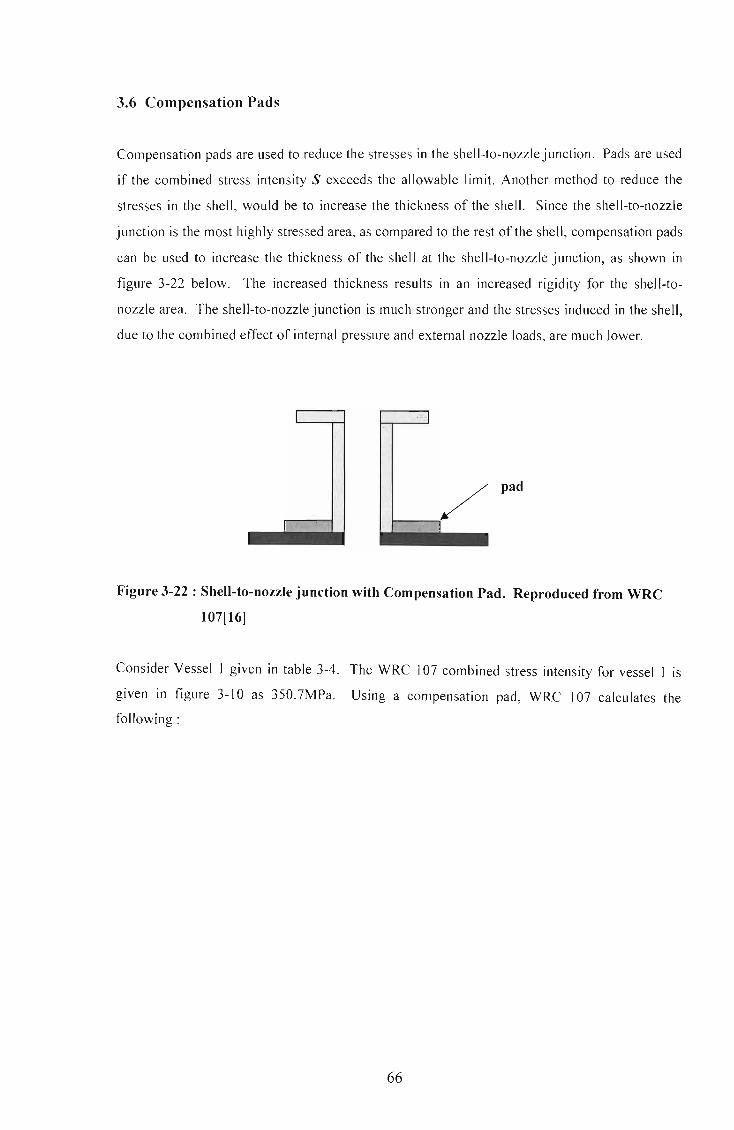
3.6 Compensation Pads
Compensation pads are used to reduce the stresses in the shell-to-nozzle junction. Pads are used
if the combined stress intensity S exceeds the allowable limit. Another method to reduce the
stresses in the shell, would be to increase the thickness of the shell. Since the shell-to-nozzle
junction is the most highly stressed area, as compared to the rest of the shell, compensation pads
can be used to increase the thickness of the shell at the shell-to-nozzle junction, as shown in
figure 3-22 below. The increased thickness results in an increased rigidity for the shell-to
nozzle area. The shell-to-nozzle junction is much stronger and the stresses induced in the shell,
due to the combined effect of internal pressure and external nozzle loads, are much lower.
L I
pad
I
Figure 3-22: Shell-to-nozzle junction with Compensation Pad. Reproduced from WRC
107[16]
Consider Vessel 1 given in table 3-4. The WRC 107 combined stress intensity for vessel I is
given in figure 3-10 as 350.7MPa. Using a compensation pad, WRC 107 calculates the
following:
66

DESIGN Internal Design pressure(DP)
Design Temperature Vessel Material Nozzle Material
CYLINDRICAL SHELL Vessel Inner Diameter(DS) Vessel Thickness(TS) Corrosion Allowance(CA) Vessel Allowable Stress(Sm) Compensation Pad Diameter(CPD) Compensation Pad Thickness(CPT)
NOZZLE (6 inch) Nozzle Outer Diameter(DN) Nozzle Thickness(TN) Corrosion Allowance(CA) Nozzle Alowable Stress(SNm)
2.51 MPA 150 DEGREES C
SA - 516 Grade70 SA - 106 Grade B
570mm 14mm
3mm 137.9MPa
290mm 14mm
168.3mm 10.97mm
3mm 117.9MPa
Nozzle Loads WRC 107 Sign Convention (SASOL LOADS) Radial Load(P) -9450 N Circumferential Shear(VC) 0 N Longitudinal Shear(VL) 0 N Circumferential Moment(MC) 4350000 Nmm Longitudinal Moment(ML) 6300000 Nmm Torsional Moment(MT) 0 Nmm
GEOMETRIC PARAMETERS WRC 107 Rm1 = (DS+TS+CPT-CA)/2 T1=TV+CPT-CA ro1=DN/2 GAMMA1=Rm1IT1 BETA 1 =0.875*ro1 /Rm 1
Rm2 = (DS+ TS-CA)/2 T2=TV-CA ro2=CPD/2 GAMMA2=Rm2IT2 BET A2=0.875*ro2/Rm2
297.50 mm 25.00mm 84.15mm 11.90 0.248
290.50 mm 11.00 mm
145.00 mm 26.41 0.437
Dimensionless loads from WRC 107 (PHI - circumferential, x - longitudinal)
Figure Gamma1 Beta1 Gamma2 Beta2 4C N(PHI)/(P/Rm) 11 .90 0.248 26.41 0.437 2C1 M(PHI)/P 11 .90 0.248 26.41 0.437 3A N(PHI)/(MC/(RmA2*BETA)) 11 .90 0.248 26.41 0.437 1A M(PHI)/(MC/(Rm*BETA)) 11 .90 0.248 26.41 0.437 3B N(PHI)/(MU(RmA2*BETA)) 11 .90 0.248 26.41 0.437
67
VALUE VALUE 1.923 2.502 0.059 0.012 0.443 0.864
0.09 0.066 1.388 1.519

1B M(PHI)/(MU(Rm*BETA)) 11 .90 0.248 26.41 0.437 0.037 0.011
3C N(x)/(P/Rm) 11.90 0.248 26.41 0.437 1.53 1.142
1C1 M(x)/P 11 .90 0.248 26.41 0.437 0.089 0.026
4A N(x)/(MC/(RmA2*BETA)) 11.90 0.248 26.41 0.437 0.769 2.645
2A M(x)/(MC/(Rm*BETA)) 11 .90 0.248 26.41 0.437 0.049 0.028
4B N(x)/(MU(RmA2*BETA)) 11 .90 0.248 26.41 0.437 0.439 0.816
2B M(x)/(MU(Rm*BETA)) 11 .90 0.248 26.41 0.437 0.061 0.017
POINTS C & D
3C N(PHI)/(P/Rm) 11.90 0.248 26.41 0.437 1.53 1.142
1C M(PHI)/P 11 .90 0.248 26.41 0.437 0.086 0.06
1 B1 M(PHI)/(MU(Rm*BETA)) 11.90 0.248 26.41 0.437 0.038 0.012
4C 11.90 0.248 26.41 0.437 1.923 2.502
2C 11 .90 0.248 26.41 0.437 0.058 0.03
2B1 11.90 0.248 26.41 0.437 0.061 0.024
STRESS CONCENTRATION FACTORS Kn=1, Kb=1
STRESS VALUES Moa - NOZZLE TO PAD JUNCTION
AU AL BU BL CU CL DU DL
CM(DP) 27.5 30.0 27.5 30.0 27.5 30.0 27.5 30.0
CM(P) 2.4 2.4 2.4 2.4 1.9 1.9 1.9 1.9
CB(P) 5.4 -5.4 5.4 -5.4 7.8 -7.8 7.8 -7.8
CM(MC) 0.0 0.0 0.0 0.0 -3.5 -3.5 3.5 3.5
CB(MC) 0.0 0.0 0.0 0.0 -51 .0 51.0 51.0 -51.0
CM(ML) -16.0 -16.0 16.0 16.0 0.0 0.0 0.0 0.0
CB(ML) -30.4 30.4 30.4 -30.4 0.0 0.0 0.0 0.0
S(PHI) -11.1 41.5 81.6 12.6 -17.4 71.6 91.8 -23.4
LM(DP) 13.7 13.7 13.7 13.7 13.7 13.7 13.7 13.7 LM(P) 1.9 1.9 1.9 1.9 2.4 2.4 2.4 2.4 LB(P) 8.1 -8.1 8.1 -8.1 5.3 -5.3 5.3 -5.3 LM(MC) 0.0 0.0 0.0 0.0 -6.1 -6.1 6.1 6.1 LB(MC) 0.0 0.0 0.0 0.0 -27.8 27.8 27.8 -27.8 LM(ML) -5 .1 -5.1 5.1 5.1 0.0 0.0 0.0 0.0 LB(ML) -50.1 50.1 50.1 -50.1 0.0 0.0 0.0 0.0
sex) -31.4 52.7 78.9 -37.5 -12.5 32.6 55.3 -10.8
SHEAR(MT\ 0.0 0.0 0.0 0.0 0.0 0.0 0.0 0.0 SHEAR(VC) 0.0 0.0 0.0 0.0 0.0 0.0 0.0 0.0 SHEAR(VL) 0.0 0.0 0.0 0.0 0.0 0.0 0.0 0.0
't 0.0 0.0 0.0 0.0 0.0 0.0 0.0 0.0
S(1) 11.1 41 .5 81.6 12.6 17.4 71.6 91.8 23.4 S(2) 31.4 52.7 78.9 37.5 12.5 32.6 55.3 10.8 S(1)-S(2) 20.3 11.2 2.7 50.1 4.9 39.0 36.4 12.6
S(PL + Q) 31.~ 52.~ 81.~ 50.1 17.~ 71.~ 91.~ 23.4
68

STRESS VALUES Mpa - PAD TO SHELL JUNCTION
AU AL BU BL CU CL DU DL
CM(DP) 63.7 66.2 63.7 66.2 63.7 66.2 63.7 66.2
CM(P) 7.4 7.4 7.4 7.4 3.4 3.4 3.4 3.4
CB(P) 5.6 -5.6 5.6 -5.6 28 .1 -28.1 28.1 -28.1
CM(MC) 0.0 0.0 0.0 0.0 -9 .3 -9.3 9.3 9.3
CB(MC) 0.0 0.0 0.0 0.0 -112.2 112.2 112.2 -112.2
CM(ML) -23.6 -23.6 23.6 23.6 0.0 0.0 0.0 0.0 CB(ML) -27.1 27.1 27.1 -27.1 0.0 0.0 0.0 0.0
S(PHI) 26.0 71.5 127.4 64.5 -26.3 144.4 216.7 -61.5
LM(DP) 31 .8 31.8 31 .8 31.8 31.8 31.8 31 .8 31.8
LM(P) 3.4 3.4 3.4 3.4 7.4 7.4 7.4 7.4
LB(P) 12.2 -12.2 12.2 -12.2 14.1 -14.1 14.1 -14.1
LM(MC) 0.0 0.0 0.0 0.0 -28.4 -28.4 28.4 28.4
LB(MC) 0.0 0.0 0.0 0.0 -47.6 47.6 47.6 -47.6 LM(ML) -12.7 -12.7 12.7 12.7 0.0 0.0 0.0 0.0 LB(ML) -41.9 41.9 41.9 -41 .9 0.0 0.0 0.0 0.0
S(x) -7.1 52.2 101.~ -6.1 -22.7 44.4 129.3 6.(l
SHEAR(MT' 0.0 0.0 0.0 0.0 0.0 0.0 0.0 0.0 SHEAR(VC) 0.0 0.0 0.0 0.0 0.0 0.0 0.0 0.0 SHEAR(VL) 0.0 0.0 0.0 0.0 0.0 0.0 0.0 0.0
T O.(l 0.0 O.(l 0.0 O.(l O.(l O.(l 0.0
5(1) 26.C 71.5 127.4 64.5 26.3 144.4 216.7 61 .5 5(2) 7.1 52.2 101.9 6.1 22·1 44.4 129.3 6.0 5(1)-5(2) 33.L 19.2 25.5 70.6 3.6 100.0 87.4 67.4
S(PL + Q) 33.~ 71.5 127.~ 70.6 26.3 144~ 216.~ 67.4
Figure 3-23 : Codecalc Computation Sheet including Compensation Pad
The initial FEM combined stress intensity for Vessel 1, as shown in figure 3-11, is 467MPa.
After modifying Model A, to include a compensation pad, the following FEM stresses were
achieved:
69

8.09+007
771+007
732+0071
694+007iiJm~
3.49+007 defaultfringe :
Max 9.24+007 @Elm 4462.2 Min 3.49+ 007 @Elrn 4017.1
Figure 3-24: Vessel 1 with Compensation Pad subjected to internal pressure alone
1.90+008
1 1.77·008 "
1.65+008
1.52+008
140+008
1 1 27+008
115+008
1 02+008
B 95+0071
769+0071
644+00711
518+0071
3.93+0071
267+0071
142+0071)
1.66+006 deloult_Fringe .
Mox 1 90+008 @Elm 4060.3 Min 1.66+006 @Elm 4948.3
Figure 3-25 : Vessel 1 with Compensation Pad subjected to external nozzle loads alone
70

2.73+006
2.55+00al
23S'008U
2.21·008
2.03 . 008
1 1.86· 008
1.69+008
1.51+ 008
1 1 34+008
116+0081
991+0071
818+0071
644+0071
2.97+007
1.24+ 007 defouhf ringe :
Max 2.73.008 @Elm 4059.3 Min 1.24+007 @Elm4180.2
Figure 3-26: Vessell with Compensation Pad subjected to both internal pressure
and external nozzle loads
The FEM stresses do not coincide with the WRC 107 stresses. WRC 107 calculates the
maximum combined stress intensity to be located at the pad-to-shell junction. However, the
FEM results, according to figure 3-26, indicate that the maximum stress occurs at the pad-to
nozzle junction. This is due to the high stresses induced by the internal pressure thrust load, see
figure 3-24, and the higher stresses created by the external nozzle loads, figure 3-25. The
combined stress intensity has been reduced from 467MPa to 273MPa. This indicates that
compensation pads are useful in reducing high stresses that exist at the shell-to-nozzle junction.
71

Chapter 4
THEORY OF BUCKLING
4.1 Theory of Stability
Load-carrying structures fail in a variety of ways. A type of failure, which is of concern for the
purposes of this study, is buckling. To illustrate the fundamental concepts of buckling and
stability, we need to study the idealized structure shown in figure 4-1 below:
B
~
L '2
A ()' . _ _ .L..-
" .'
Figure 4-1 : Buckling of an Idealized Structure. Obtained from Gere and Timosbenko[33]
The structure represents two bars, AB and BC, each of length Ll2. They are joined by a pin
connection at point B and held in a vertical position by a rotational spring with a spring constant
of PR. An axial compressive load P is applied and is vertically aligned along the longitudinal
axis of the bars. Initially the spring is unstressed and the bars are in direct compression.
Suppose the structure is disturbed by some external force that causes point B to deflect a small
distance laterally. The two bars rotate through small angles e about points A and C,
respectively. A restoring moment develops in the spring, which tends to return the bars to their
original straight positions. At the same time the axial force acts to increase the lateral
deflection, thereby acting opposite to the moment. If the axial force P is relatively small, the
restoring moment is the more dominant force and will return the structure to its original
position. Under these conditions the structure is said to be stable. However, if the axial force P
72

is greater than the restoring moment, point B will continue to deflect and the bars will rotate
through larger and larger angles until the structure will eventually collapse. This failure is
referred to as buckling and the structure is deemed unstable.
The restoring moment MB is equal to the rotation stiffness PR times the angle of rotation 2 e of
the spring:
( 4.1)
The lateral displacement of point B 1S eLl2. We thus obtain the following equation of
equilibrium:
(4.2)
Substituting equation 4.1 into 4.2 gives:
(4.3)
To ensure that the structure is stable, we obtain a critical load (for axial load P) from the above
equation:
(4.4)
The following conditions are developed:
• If P < Pen the structure is stable (no buckling).
• If P > Pcn the structure is unstable (buckling occurs).
When the axial load is less that the critical load (0 < P < Pcr), the structure is in equilibrium
when it is perfectly straight (e = 0). If a disturbance occurs, the structure will return to its
original position and the equilibrium is deemed stable. When P > Per , the structure is still in
equilibrium when e = 0 (no moment in spring, structure in direct compression), but the
equilibrium cannot be maintained and is deemed unstable. The slightest disturbance will cause
the structure to buckle. When the axial load equals the critical load, the structure is still in
equilibrium for any value of e. The structure is neither stable nor unstable. This condition is
referred to as neutral equilibrium. The equilibrium conditions are shown in figure 4-2 below,
representing the graph of axial load P against the angle of rotation e.
73

p
<E------Unstable equilibrium
B ~Neutral equilibrium
<E------ Stable equilibrium
o ()
Figure 4-2 : Equilibrium diagram for idealized structure. Reproduced from Gere and
Timoshenko[33]
The two heavy lines, one vertical and one horizontal, represent the equilibrium conditions.
Point B is called the bifurcation point (see Fung and Sechler[12]). The neutral condition extends
to the left and right of the vertical axis because the angle () may be clockwise or
counterclockwise. The angle is assumed small, therefore, the line extends a short distance. This
assumption is valid since () is small when the structure first departs from its vertical position
and buckling begins. Thin-walled shells[8] are subjected to compressive forces in extensive
areas. The question arises as to whether the equilibrium of such shells is stable. A shell
carrying a certain load or basic load produces basic stresses and basic displacements. The
equilibrium is disturbed by imposing a small additional deformation, by some external force.
The equilibrium is stable if the external force is removed and the disturbance (a system of
additional stresses and displacements occurring spontaneously) vanishes. When the basic load
is increased, a less external force is needed to produce the same disturbance until a certain
disturbance becomes possible without any external force. The equilibrium and this point is
deemed neutral. The smallest value which the basic load must assume to reach neutral
equilibrium is the critical load or buckling load. When the critical or buckling load is exceeded,
the equilibrium becomes unstable and any disturbance can cause the shell to buckle or, perhaps,
eventually collapse. To find the critical load we formulate the differential equations for the
disturbed equilibrium without an external disturbing load . These equations also include new
terms for the additional stresses caused by the disturbing load. Since the disturbance is assumed
to be very small, these new terms must be of the same order of magnitude. These terms indicate
that the basic load is now acting on a slightly deformed element. Since the conditions of
equilibrium are satisfied, and Hooke ' s Law expresses stresses in terms of displacements, we
obtain homogenous linear differential equations for the displacements u, v and w (shell theory).
74

4.2 Buckling of Shells
4.2.1 Differential Equations of Equilibrium
Deformation ofa cylindrical shell is defined by the displacements u, v and w. This is illustrated
in figure 4-3 below:
u
z x
v v
y y
Figure 4-3: Cylindrical Shell showing displacements. Reproduced from Timoshenko[l]
The figure above shows that the displacements in the x, y and z directions are denoted by u, v
and w respectively. Differential equations for these displacements are needed to examine the
behaviour of cylindrical shells under the combined loading of radial and axial external
pressures. By considering the equilibrium of an element of a cylindrical shell, figure 4-4, it is
possible to determine relationships between edge moments, shear forces and edge forces.
Figure 4-4 is shown below:
75

o dy = rdO
C A
aN N + -Y. dy
Y ay
C A
aM M + __ x. dx x ax
B
Figure 4-4 : Element of Cylindrical Shell. Obtained from Bulson and Allen[17]
Before deformation, the axes x, y and z are tangent to the element in the longitudinal direction,
tangent to the element in the circumferential direction and normal to the middle surface of the
shell respectively. After deformation, which is assumed to be very small, these directions are
altered slightly. The z axis is now normal to the deformed middle surface of the shell , the x axis
is tangent to the deformed element in the longitudinal direction and the y axis is perpendicular
to the xz plane. The directions of the resultant forces will also be changed slightly and these
changes must be considered in writing the equations of equilibrium of the element OABC.
Firstly, the angular displacements of sides BC and AB with respect to sides OA and OC of the
element has to be established. The rotation of side BC with respect to side OA can be resolved
into three components with respect to the x, y and z axes. Rotation of the sides OA and BC with
respect to the x axis is due to displacements v and w. Since the displacement v represents the
motion of the sides OA and BC in the circumferential directions (see figure 4-4) and r is the
76

radius of the middle surface of the cylinder, the corresponding rotation of the side OA, with
respect to the x axis, is v/a and that of the side BC is :
1 ( av ) - v+-dx r ax
(4.5)
Thus, owing to displacement v, the relative angular motion of BC with respect to OA about the x
aXIs IS :
~ av dx r ax
(4.6)
Owing to displacement w, the side OA rotates with respect to the x axis by the angle aw f(raB) ,
and the side BC by the angle:
aw a aw --+---dx raB ax raB
Thus, because of displacement w, the relative angular displacement is :
~ aw dx ax raB
(4.7)
(4.8)
Combining equations 4.6 and 4.8, the relative angular displacement of the side BC with respect
to the side OA about the x axis is :
(4.9)
The rotation of side BC with respect to side OA about the y axis is due to bending of the axial
(longitudinal) plane and is equal to (sign convention is determined using the right-hand rule) :
(4.10)
77

The rotation of side BC with respect to side DA about the z axis is due to bending of the
tangential (circumferential) plane and is equal to :
(4.11 )
The last three expressions, equations 4.9 - 4.11, give the three components of rotation of side
BC with respect to side DA.
The corresponding formulas for the angular displacement of the side AB with respect to DC has
to be established. Due to the curvature of the cylindrical shell, the initial angle between the
axial sides of element DABC is dB. However, because of displacements v and w, this angle will
change. The rotation of the axial side DC with respect to the x axis can be expressed as :
v Ow -+-r r8B
The corresponding rotation of axial side AB being:
The initial angle is changed to :
v 8w 8 (v 8W) -+-+- -+- dB r r8B 8B r r8B
dB+dB( 8v + 82w)
r8B r8B 2
( 4.12)
(4.13)
(4.14)
To calculate the angle of rotation of side AB with respect to side DC about the y axis, one needs
to determine the expression for twist. It is observed that after deformation the element rotates
about the y axis through an angle of - Ow / 8x and with respect to the z axis through an angle of
8v / 8x . If one considers an element a distance rdB from the first one, it is observed that its
rotation about the y axis, corresponding to displacement w, is :
(4.15)
78

Rotation of the same element in the plane tangent to the shell is :
Ov + a(av/ ax) dB ax aB
The latter rotation has a component with respect to the y axis and is equal to :
_ av dB ax
( 4.16)
( 4.17)
Therefore, the angular displacement of side AB with side QC about the y axis is given using
equations 4.15 and 4.17, and is equal to :
-(~+ avJdB aBax ax
(4.18)
Rotation of side AB with respect to QC about the z axis is due to displacements v and w. Owing
to displacement v, the angle of rotation of side QC is Ov / ax and that of side AB is given by
equation 4.16. The relative angular displacement is :
~dB aBax
( 4.19)
Due to displacement w, the side AB rotates in the axial plane by the angle aw / ax . The
component of this rotation with respect to the z axis is :
aw - - dB ax
( 4.20)
Combining equations 4.19 and 4.20, the relative angular displacement about the z axis of the
side AB with respect to the side QC is obtained.
(~- awJdB aBax ax (4.21)
79

Having the formulas for the angles, the three equations of equilibrium of element OABC can be
obtained. This is achieved by projecting all the forces onto the x, y and z axes. The x
component of those forces parallel to the resultant forces N.r and Nl'x are:
aN _x dxrdB ax
aN ~dBdx
aB
( 4.22)
Due to the angle of rotation, equation 4.21, the forces parallel to NI' give a component in the x
direction:
-N ---- dBdx ( a2v awJ
Y aBax ax (4.23)
Due to the rotation given in equation 4.11 , the forces parallel to the resultant forces Nxy have a x
component of:
(4.24)
Finally, due to the expressions of the angles given in equations 4.10 and 4.18, the forces parallel
to Qx and Qy gives x components of:
a2w (a
2w avJ -Q -dxrdB-Q --+- dBdx
x ax 2 Y aBax ax
(4.25)
The expressions for the projections in the x direction, calculated above, are combined, as well as
expressions for the y and z directions. For radial pressure a normal pressure intensity of q is
used with zero projections on the x and y axes. After simplification, the three differential
equations of equilibrium for displacements u, v and ware, repectiveiy :
80

(4.26)
r __ x +--+N -+-- +rN --+N 1+-+-- +N -+-- + r=O aQ aQy (av a2
W J a2
W ( av a2
W J (av a2
W J ax aB xy ax axaB x ax 2 y raB raB 2 yx ax axaB q
The above equations relate edge forces to shear forces. Similarly we can obtain equilibrium
equations that relate edge moments to shear forces. We obtain three equations of moments with
respect to the x, y and z axes (figure 4-4). Again, we take into consideration the small angular
displacements of the sides BC and AB with respect to DA and DC respectively. The three
equilibrium equations are:
aM yx aM x a2v (a
2v 8wJ --"-+r--+rM --M ---- -rQ =0
aB ax xy ax 2 Y axaB ax x (4.27)
81
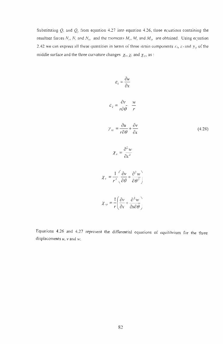
Substituting Qx and QI' from equation 4.27 into equation 4.26, three equations containing the
resultant forces N." NI' and N x.l' and the moments Mx , M I, and Mry are obtained. Using equation
2.42 we can express all these quantities in terms of three strain components Cl, C2 and /"ry of the
middle surface and the three curvature changes Xx, XI' and Xry, as :
au & =) ax
av w &2 =----
rae r
( 4.28)
Equations 4.26 and 4.27 represent the differential equations of equilibrium for the three
displacements u, v and w.
82

4.2.2 Cylindrical Shells under External Axial and Radial Pressure
Using the differential equations of equilibrium, the critical buckling strength of a cylindrical
shell can be determined under the combined loading of external axial and radial pressure.
Initially, shells subjected to external axial pressure will be considered. For shells under external
axial pressure we assume that all resultant forces, except Nn are very small. The products of
these forces with the derivatives of the displacements u, v and w, which are also small, are
neglected. Thus, equations 4.26 become:
8N 8Nyr r __ x +-_._" =0 8x 8B
(4.29)
For equations 4.27, we neglect the products of moment and derivatives of the displacements u, v
and w. The equations become:
Q = 8Mx + 8Myx
x 8x r8B
8M y 8M Q =--" -~
y r8B 8x
(4.30)
Substituting equations 4.30 into equations 4.29 the three equations of equilibrium for buckling
of an axially compressed cylindrical shell becomes:
83

aN " aNn r __ J +-"-" =0 ax aB
aN )' aN ),x N a2v aMxy aMy 0 --+r--+r -+----- = (4.31) aB ax x ax 2 ax raB
a2M xl, --" =0 axaB
The resultant forces and moments are expressed using equations 2.42. Substituting equations
4.28 into 2.42 produces:
ET (au (av w)J Nx = 1 _ v2 ax + v raB --;
N =~((~- w)+vauJ y 1- v2 raB r ax
N = ET (au + av) - N xy 2(1 + v) raB ax - yx
84
(4.32)

and substituting equations 4.32 into 4.31, finally produces :
Equations 4.33 represent the differential equations of equilibrium for a cylindrical shell
compressed under axial pressure. One also needs to consider a cylindrical shell compressed
laterally under radial pressure. For this condition, the differential equations of equilibrium are
determined and the following assumptions are made. Firstly, all resultant forces, except Ny , are
small, and the products of these with the derivatives of displacements u, v and w can be
neglected. All bending and twisting moments are small, and the products of these with the
derivatives of displacements can be neglected as well. Substituting the above conditions into
equations 4.26 and 4.27 produces:
85

aN' aN vx (a2v awJ 0 r--·I +----N ---- =
ax aB y axaB ax
aNy aNxy Q _ 0 --+r--- -aB ax ' y
aQ aQ (av a 2 w J r __ x +--y +N 1+--+--2
+qr =0 ax aB Y raB raB
aMx
aMyX Qx =a;-+ raB
aM y aMxy Q - -=-----
y raB ax
Substituting equations 4.35 into 4.34, produces:
aNy aNXY
aMy aMXY --+r-----+--=O aB ax raB ax
(4.34)
(4.35)
( 4.36)
Due to the action of uniform external radial pressure, the following assumption is made. The
circular cylindrical shell remains circular and only undergoes compression in the
circumferential direction, so that Nn Mn My, Mxy = 0 and
N y =-qr+N~ (4.37)
86

NJ.' is a small change in the resultant force - qr. With the stretching of the middle surface of the
shell during buckling, N/l+c/} and q(J+c/} (J+cJJ are used for Nv and q respectively in the
au (]v w Since, £1 =- and £2 =----, and ax rae r
second and third equations of equations 4.36.
substituting equation 4.37 into equations 4.36, produces:
aN;, aN,y aM v aM Xl'
--+r-----· +--' =0 ae ax rae ax (4.38)
Substituting equations 4.32 into equations 4.38, produces:
(4.39)
87

The differential equations of equilibrium for a cylindrical shell compressed both axially and
laterally under uniform external pressure can be detem1ined. Using the notations :
(4.40)
equations 4.33 and 4.39 are combined to obtain the following three equations:
(4.41 )
88

a2 w The edges are assumed to be simply supported w = 0 and --2 = O. The general solutions of ax the displacement Lt, v and w for a cylindrical shell compressed both axially and laterally are
represented below ( r - radius of shell, I - length of shell) :
A · e m1lX U = SInn cos--
I
e . m1lX v = Bcosn SIn--
I
C · e ' m1lX W= SInn SIn--I
(4.42)
The above equations indicate that during buckling the shell buckles into m half-waves in the
longitudinal direction and 2n half-waves in the circumferential direction. Substituting equations
4.42 into 4.41, three homogeneous linear equations are obtained for A, B and C. The equation
for calculating the critical buckling pressure is determined by equating the determinant of these
equations to zero. After simplification, the equation derived from equating the determinant to
zero is :
where
Cl = (1- v 2 ),14
C2 = (A? +n2y -2[vA6 +3A4n2 +{4-v)A2n4 +n 6 ]+2{2-v)A2n2 +n4
C3 =n2(A2 +n2y -(3A2n2 +n4)
C4 = ,.1,2(,.1,2 + n2 Y +A2n2
and
89
(4.43)
(4.44)

The buckling condition contains four unknowns i.e. The dimension less loads rp, and rp2 and the
modal parameters nand A. It is known that n must be an integer (0,1,2'00') and A must be an
integer multiple (1,2,3 ' 00') of trr. Equation 4.43 represents a linear relationship between I
quantities rp, and rp2. If one keeps m constant and give to n the values 2, 3, 4,00', a system of
straight lines is obtained as shown in figure 4-5 below.
unstable
rp]
Figure 4-5: Stable and Unstable regions in the rp1 and rp2 plane. Reproduced from Flugge
[8]
The origin rp, = rp2 = 0 represents the unloaded shell. When a load is applied, the path shown in
figure 4-5 by the dotted line is followed. The cylindrical shell is in stable equilibrium if it does
not meet any of the curves. When one curve is reached the equilibrium becomes neutral. The
region enclosed by the envelope ofthe curves is stable, however the region outside the envelope
is regarded unstable. Taking the points of intersection of these curves with the horizontal axis
(rp2 = 0) we obtain the critical values of rp, when lateral pressure acts alone. In the case of
lateral pressure acting alone, the buckled shape has only one half-wave length in the axial
direction m = 1, and the critical pressure increases as A increases and the length of the shell
decreases. Taking the points of intersection of the same curves with the vertical axis (rp, = 0)
we obtain the critical values of rp2 when axial pressure acts alone. For any given value of the
ratio rpl / rp2 one draws through the origin a straight line with slope rpl / rp2. The points of
intersection of this line with the polygons generated by the curves determine the corresponding
critical values of rp, and rp2. Tt is observed that axial pressure causes the critical value of the
lateral pressure to decrease and lateral pressure causes the critical value of the axial pressure to
90

decrease. The most common case is that of a cylindrical shell with closed ends under uniform
1 external pressure. This case indicates that 92 = - 91 . Assuming that the shell is thin and in
2
keeping only the principal terms of equation 4.43, the critical buckling pressure for a cylindrical
shell under external axial and radial pressure, is obtained:
qcr = (4.45)
The above equation was derived by R von Mises in 1929[2].
91

4.3 Finite Element Buckling Analysis
In a linear static analysis a structure is assumed to be in a state of stable equilibrium. When the
load is removed the structure returns to its original undeformed position. However, buckling
occurs due to the structure continuing to deform without any increase in the applied loading.
The structure has become unstable. Various FEM packages or MSC P A TRAN have developed
elastic or linear buckling analysis, to determine the buckling load for a particular structure. The
analysis assumes that there is no yielding of the structure and the direction of the applied
loading does not change.
The elastic buckling analysis creates a differential stiffness, in addition to the system stiffness
matrix, and includes the higher-order strain displacement relationships that are functions of the
geometry, element type and applied loads. The differential stiffness represents a linear
approximation of reducing the stiffness matrix for a compressive load and increasing the
stiffness matrix for a tensile load.
In a buckling analysis eigenvalues (see Walker[37] and Dahlgren[41]) are solved. These
eigenvalues represent scale factors that are multiplied to the applied load to produce the critical
buckling load. In general, the lowest buckling load is of interest, since the structure will fail
before reaching any higher-order buckling loads. Therefore only the smallest eigenvalue needs
to be calculated. The buckling equation used by MSC PA TRAN is (Equation 4.46 was also
derived by energy methods) :
(4.46)
K is the system stiffness matrix, Kd is the differential stiffness matrix, generated automatically
by MSC PATRAN, and Ai are the eigenvalues to be computed. Once the eigenvalues are found,
the buckling load is solved for
F =1F er /l,.. i a (4.47)
where Fcr is the critical buckling load and Fa is the applied load.
92

4.3.1 Stability and Energy Methods
The stability of a structure can be determined with the aid of energy methods. Consider the
three cases of equilibrium of the ball shown in figure 4-5 below:
(a) (b) (c)
Figure 4-6 : Ball in stable, unstable and neutral equilibrium. Obtained from Timoshenko
[1]
In figure 4-5(a) the surface is a concave spherical surface or shaped like a dish. The equilibrium
is stable since the ball will always return to its position of equilibrium or low point when
disturbed. In figure 4-5(b) the surface is a convex spherical surface or shaped like a dome. The
equilibrium is unstable because if the ball is disturbed, it will roll away and not return to its
position of equilibrium. In figure 4-5(c) the surface is perfectly flat, therefore, the ball is in
neutral equilibrium and remains wherever it is placed. The type of equilibrium can be
ascertained by considering the energy of the system. In the first case, figure 4-5(a), any
displacement of the ball from its position of equilibrium will raise its center of gravity.
Therefore, the potential energy of the system is increased. In the second case, figure 4-5(b),
any displacement of the ball from its position of equilibrium will lower its center of gravity and
the potential energy of the system will decrease. The third case, figure 4-5(c), there is no
change in the ball's center of gravity, therefore, the potential energy of the system remains
unchanged. It can be concluded that for stable equilibrium the potential energy of the system is
a minimum (concave) and for unstable equilibrium the potential energy of the system is a
maximum (convex). To obtain stable equilibrium, the potential energy of the system must be
minimized with respect to the system's deflection:
(4.48)
93

4.3.2 Finite Element Method
Consider the individual element of an isotropic plate shown 111 figure 2-12. It has been
discussed that the total strain energy for the element[ 17] is :
(4.49)
This can be derived from equations 2.53 and 2.73. For the entire plate the above equation
becomes:
(4.50)
The element is now loaded with an external compressive stress a: The compressive stress can
be divided into stresses in the axial (longitudinal), 0:.:, and radial (circumferential), 0 "
directions. U sing similar methods for calculating the total strain energy for the plate[ I 7]
element, the work done by the compressive stress is given by :
(4.51 )
Kc is referred to as the geometric stiffness matrix. It is so called because the terms
representative of instability effects are geometric in nature. The total potential energy of the
plate is :
(4.52)
94

The above equation can be rewritten as :
~ = ~[[K]+ [Kc ]]{o} (4.53)
and using equation 4.48 one obtains:
(4.54)
The objective is to determine the critical buckling load, Fer. Kc contains the terms related to the
applied compressive load, therefore the above equation can be written as :
(4.55)
Substituting equation 4.47, produces:
[ [K 1 + Vo [ k d ]Jo) = 0 (4.56)
[[K]+ )jKd ] ]{o} = 0 (4.57)
Since the deflections are not equal to zero, the above equation has a nontrivial solution. This is
in the form of an eigenvalue problem, therefore, the eigenvalues are determined by finding the
determinant of [[K]+A-;[Kd ]] and equating it to zero (equation 4.46). The lowest
eigenvalue is determined to produce the lowest critical buckling load using equation 4.47. Any
applied load, greater than the critical buckling load, makes the plate or shell structure unstable.
Therefore, failure due to buckling occurs.
95

Chapter 5
VESSELS UNDER EXTERNAL PRESSURE AND PIPING LOADS
5.1 Design of Pressure Vessels Under External Pressure
5.1.1 Literature Survey
For thin-walled vessels, buckling (see Ross[26]) over an extensive region must be considered.
Presently, pressure vessels are designed to withstand failure due to buckling by determining a
critical load. Pressure vessels with loads greater than that of the critical value will give rise to
much larger and permanent deformations. As a result, buckling is said to occur and complete
collapse of the vessel will result.
For vacuum operations, buckling or elastic instability occurs due to the imposition of an
external force or pressure. A cylindrical vessel subjected to external pressure alone has a
circumferential compressive stress equal to twice the longitudinal compressive stress. This
larger circumferential compressive stress results in the vessel collapsing due buckling or elastic
instability.
Long, thin cylinders will buckle at stresses below the yield point of the material being used.
This can be best understood by a comparison with a rod. A rod in tension can carry a load even
after the yield point of the material is reached, while a rod in compression might bend and not
be able to carry an increased load at stresses below the yield point. This implies that a long thin
vessel will collapse at very low stresses under external pressure.
The degree of stability of a vessel under external pressure depends on its length, thickness and
diameter. Therefore, pressure vessels can be divided into three categories:
• Short Vessels : The vessel collapses near the yield point of the material. The
influence of length on the vessel is negligible.
96

• Vessels of Intermediate Length: The vessel collapses by unstable buckling. The
collapsing pressure depends on the tlD ratio and LID ratio; t - thickness, D -
diameter, L - length.
• Long Vessels : The shell collapses by unstable buckling. The collapsing pressure
depends principally on the tlD ratio.
For this study, vessels with intermediate length will be used where the collapsing pressure
depends all three factors: thickness, diameter and length.
Several formulas have been developed for the computation of the buckling pressure of vessels
under external pressure. The first and most accurate formulas were derived by R von Mises in
1929 (formula 4.45). His formula for the buckling pressure of a vessel subjected to external
axial and radial pressure, related to the vessel's outer diameter, is shown below:
2 1 ( 7rDo)2 n +- --2 2L
(5.1)
The values of n, the number of circumferential waves or lobes (figureS-I), which makes this
expression a minimum, is taken from figure 5-2.
n waves
Figure 5-1 : Buckled Cylinder. Obtained from Bulson and Allen(17)
97

20 '10-3
15 .10-3
10 9 8 1 6
TlDo 5 4.5 4.0 3.5 3.0 2.5 2.0
1\ \ 1\ Chart for \ r\ \
Number of Lobes [\ r\ , , \
f\ " '? ~" "\ ., 'p. ~, r'\. '\ '\ ....\ I\,",~ t-."""""" ,~ \. \. ~ \ y' \
........." " " " . \ .,,, 6' \ ............. I'\.. , .~..:,..l: \ \ i\
t'-.... " '" '" \. ,,:>?~ rP ,\ r-.... ........ "\. .... ~~ 1\ 1\ 1\ \ \ ,,"~ ? ~,' ,,~z ~ -" \ \ \
d\\\\'\\ :"6,, /., ~~ \L\ l\:,\ 1\ 1\ 't\ \
\ I ~
L\ ~ ? tr
" 1\ , \
\ \ \ \ \ \ \ ~
\
1\ \ \
\ \
1\ 1\ 1.5 0 0.1 0.15 0.20 0.30 0040 050 Q.6O 0.80 1.0 1.S 2.0 2.5 3.0 4.0 50 6D 8.0 kI.O
Figure 5-2 : Chart for number of lobes n. Obtained from Timoshenko[l]
For long vessels equation 5.1 is reduced to :
(5 .2)
Southwell[2] later developed the following equation fo r vessels under radial pressure alone :
(5.3)
Using the above equation, he later developed an approximate formula, independent ofn :
98

(5.4)
The buckling pressures were restricted for vessels of L < La. The critical length of a vessel is
the minimum length beyond which the resistance of the vessel to collapse, due to external
pressure, is independent of the length. Southwell derived the following formula:
L = 4F61r~h_v2 . D ~ T cr 27 0 D
o
(5 .5)
Taking v = 0.3, for carbon steel, the above equation reduces to :
(5.6)
Southwell ' s formula is differentiable. Thus an equation for n could be developed. The value
for 11 to be used in the formulas is the integral value which makes the buckling pressure a
minimum. An approximate value could be obtained from the following :
3 2(1 2)1 / 2 - ff -v n = 4 -::-'4 __ ...,....-,-__ ....,-
(L I DoY(T I DJ (5.7)
99

In 1934, at the U.S . Experimental Model Basin, Windenburg and Trilling[9] derived an
approximate formula to equation 5.1 , independent of n, to determine the critical buckling
pressure for a vessel under external axial and radial pressure :
242£ (~J" P = ...,.------:-- ----'---'-'-----
er (1- v 2 Y'4 _L _ O.4S(_T JI /2 Do Do
(5.8)
Taking v = 0.3, for carbon steel, and ignoring the second term in the denominator since it has no
discernible effect, one obtains :
(5.9)
The above equation's results deviates about one percent from equation 5.1. On account of this
formula's simplicity it is recommended for the design of vessels shorter than the critical length.
The ASME Code incorporated this formula to create their procedures for the design of pressure
vessels for external pressure.
100

ASME DESIGN CRITERIA
Long Cylinders
If the length of the vessels is greater than the critical length then the collapsing pressure is given
by equation 5.2. The critical length is determined by equation 5.6. The buckling mode n = 2,
makes equation 5.2 a minimum. Therefore, substituting n = 2 into equation 5.2 gives:
(5.10)
Short Cylinders
In these vessels failure is by plastic yielding at the yield strength of the material. The influence
of the length of the vessel is negligible. The critical pressure is given by the following:
(5 .11)
Intermediate Length Vessels
The collapsing pressure for vessels, whose lengths are less than the critical length, is given by
Windenburg and Trilling's equation 5.9.
101

For the design of pressure vessels under external pressure the ASME VIII Code developed the
Geometric Chart and the Material Chart. The geometric chart values for strain were developed
using the following strain equation :
O"cr &=-
E (5.12)
PD where O"cr = ~ (hoop stress equation). For long cylinders equation 5.10 is used to obtain:
2T
(5 .13)
For intermediate length cylinders one uses equation 5.9 and obtain :
(5.14)
The strain produced is represented in the Geometric Chart by the factor A. The Geometric
Chart is represented by figure 5-3 below:
102

10.0
a.o
.00001
\ \ , \
1\1\[\ \ '\
FACTOHA
Figure 5-3: Geometric Chart for Cylindrical Vessels under External Pressure. Obtained
from Harvey[20]
103

The Material Chart is used to determine the external allowable pressure, and is basically made
up of stress-strain curves for the material at various design temperatures. Factor A mentioned
above is plotted against factor B :
B = (Je,.
2
The Material Chart is shown in figure 5-4 below:
E - 211.0.10' E-27.o.10·
E - 24.$010'
E - 22.8.10'
E-:lD ... l0'
11111 2 3 456789
.00001 .0001
~ V ./
IJ V ./
~ 10- L...-:: III 1/
UJ J. IJj
11/ I"'- I-.... VII -.... ....... W b>.
r- ] V
~ ?W 2 3 4 56789
.001
/ I--" V ~
..... ~ ...-V i-"" ~I-' ~ -..... ~ 1--'1'""" .-
...... !--" ~" ....... 1--'''
2 3 456789
.01
FACTOR A
10-I-' -
l ~I J,J , , eoc"
f--' ~ I I 700' -
~ , I
~ V ~~-lOCH
!--" l-"iI'"
2 3 4 5 6 78 9
.1
(5 .15)
25,000
20,000 18,000 16,000 14,000 , 2,000
'~OO 00 ,
8,000 7,000 6,000
5,000
4,000 3,500 3,000
2,500
Figure 5-4 : Material Chart for Cylindrical Vessels under External Pressure. Obtained
from Harvey[20]
The procedure used by the ASME Code is as fo llows:
• Determine the LIDo and T1Do ratios.
• Using these ratios use the Geometric Chart to determine factor A.
• Using the Material Chart and factor A, determine factor B for the appropriate design
temperature.
104
CD ~
0 t1 "' u-

The ASME Code uses a safety factor of 3 for the allowable external pressure, therefore:
4B
3Do I T (5.16)
For a perfect circular, cylindrical vessel the collapsing pressure can be determined with the
above equation. For vacuum conditions the external pressure is mainly atmospheric
pressure[26]. If the applied or atmospheric pressure is less than the above allowable pressure,
the vessel is safe under buckling. If the applied pressure is greater than the allowable pressure,
the vessel will collapse under buckling. The thickness of the vessel can then be increased to
raise the allowable pressure, thereby ensuring that the applied load is lower and the vessel will
not buckle under external pressure.
5.1.2 Numerical Results
For this study, typical medium and large diameter vessels have been chosen. The vessels
subjected to external atmospheric pressure are shown below
Vessel Outer Thickness Corrosion Length External
Diameter (mm) Allowance (mm) Pressure
(mm) (mm) (MPa)
1 2800 8 - 2000 0.1
2 2800 10 - 2000 0.1
3 2800 12 - 2000 0.1
4 2800 14 - 2000 0.1
5 2800 16 - 2000 0.1
6 2800 20 - 2000 0.1
7 1200 8 - 2000 0.1
8 1200 10 - 2000 0.1
9 1200 12 - 2000 0.1
10 1200 14 - 2000 O.l
11 1200 16 - 2000 0.1
12 1200 20 - 2000 0.1
Table 5-1 : Vessels under External Pressure
105

Theoretical buckling pressures are calculated using the equations given above. The ASME
Code procedures for designing pressure vessels under external pressure, are also programmed
into the CodeCalc software. The CodeCalc format for the results can be found in Appendix C.
The FEM model , Model B, for analyzing the above vessels under external pressure, is shown
below
Isometric View
Figure 5-5 : FEM Model B
Shell elements or 4-noded quadrilateral elements were used to mesh the model. MSC PA TRAN
has a node limit of 6000 nodes, therefore, vessels using Model B were meshed[2] as close to
6000 nodes as possible to generate an appropriate fine mesh. The material of the shell is SA
516 Grade 70 (carbon steel). An elastic modulus of200GPa and a poisson's ratio of 0.3 were
used.
106

Theoretical critical buckling pressures and FEM values were generated. The results are shown
below
• 1.046 0.900
3
Vessels
. 1.557
. 1.320
4
Figure 5-6 : Comparison of ASME and FEM Critical Buckling Pressures
14.000
12.000
10.000
ro- 8.000 Cl.
~ t
6.000 Cl.
4.000
2.000
0.000
7
1.323 1.140
•2.397 1.980
8
•3.57 3.090
9
Vessels
. 5.104
. 3.960
10
Figure 5-7: Comparison of ASME and FEM Critical Buckling Pressures
• • AS ME FEM
107
. 2.126
. 1.800
5
. 7.069
. 4.830
11
3.695
•
2.53!
6
12.533 •
6.6~
12

4.000
3.500
3.000
2.500
~ Q.
~ 2.000 Q.u
1.500
1.000
0.500 0.385 0.318
0.000
. 0.667 0.555
2
• 1.046
. 0.875
3
Vessels
. 1.557
. 1.287
4
. 2.126
. 1.797
5
3.695
•
6
Figure 5-8: Comparison of Windenburg & Trilling and FEM Critical Buckling Pressures
14.000
12.000
10.000
~ 8.000 Q.
~ ij
6.000 Q.
4.000
2.000 1.323 1.132
0.000
7
•
2.397 1.978
8
•
3.57
3.120
9
Vessels
15.104 4.587
10
. 7.069
. 6.405
11
12.533
• 11.1~
12
Figure 5-9: Comparison of Windenburg & Trilling and FEM Critical Buckling Pressures
• • AS ME FEM
108

4.000
3.500
3.000
2.500
co a. ~ 2.000
0.." 1.500
1.000
0.500 0.385 0.329
0.000
1.046
• 0.950 . 0.667
0.583
2 3
Vessels
. 1.557 • 1.347
4
. 2.126
. 1.900
5
Figure 5-10: Comparison of R Von Mises and FEM Critical Buckling Pressures
14.000
12.000
10.000
co 8.000 7.069 a. ~ • 6.923 a.
u 6.000
. 5.104 4.822
4.000 3.57
. 2.397 • 3.215
2.000 1.323 2.032
1.202
0.000
7 8 9 10 11
Vessels
Figure 5-11 : Comparison of R Von Mises and FEM Critical Buckling Pressures
• • ASME FEM
109
3.695 • 3.4s1
6
12.889
12.51
12

50.0
45.0 c
4A
40.0 ~ 35.0 -,
.31 .5 .31.7 30.0 ...
0 ... ... 25.0 w :::!! 0 .22.4
20.0 .17.4
15.0. 14.3 .14.5 .14.0 .15.2 .15.3
.13.8 .13.4
10.0
5.0 ~
0.0 -,-----
2 3 4 5 6 7 8 9 10 11
Vessels
Figure 5-12 : Percentage errors between ASME and FEM Critical Buckling Pressures
Figure 5-13 : Percentage errors between Windenburg & Trilling and FEM Critical
Buckling Pressures
110
12

18.0
16.0 J .15.2
.14.6 14.0 ~ .13.5
12.0 .12.7
.10.6 .9.9 10.0
.9.1 .9.1 ... 8.0 0 ... ... w .6.4 ~ 6.0 " .5.5 0
4.0 "
2.0 " .2.1
0.0
1 2 3 4 5 6 7 8 9 10 11 12 -2.0 ~
-2~ -4.0 J
Vessels
Figure 5-14: Precentage errors between R Von Mises and FEM Critical Buckling
Pressures
The results indicate that the FEM and Von Mises critical buckling pressures coincide the best.
The ASME critical buckling pressures differ due the safety factor of 80% that exists in the
material chart, which is needed to determine the factor B. To verify Model B, analyses to
determine the theoretical and FEM number of lobes of buckling n were made. The following
results were obtained:
111

Vessel n (Figure 5-2) n (equation 5.7) nFEM
1 8 8 9
2 8 8 8
3 8 8 8
4 7 7 8
5 7 7 7
6 7 7 7
7 4 4 5
8 4 4 5
9 4 4 4
10 4 4 4
11 4 4 4
12 4 4 4
Table 5-2 : Comparison between Theoretical and FEM lobes of buckling n
Top View
Figure 5-15: FEM Buckling pattern for Vessel 7
The number of lobes of buckling n coincides with the theoretical values, thereby verifying
Model B. The FEM results can be found in Appendix C.
112

5.2 Design of Pressure Vessels under External Pressure and Piping Loads
The shell-to-nozzle region is a localized area and nozzle loads are regarded as local loads being
applied to this region. Therefore, the combination of external pressure and nozzle loads will
result in local buckling (see [20], [38] and [39]) occurring at the shell-to-nozzle junction. This
can be illustrated in the figure below
external pressure + nozzle loads
.XI.rut pressure
Figure 5-16 : Local Stresses exceeding Critical Buckling Stress. Reproduced from
Harvey[20]
It has been discussed that, to prevent buckling from occurring, stresses should be less than the
critical buckling stress O'er. However, at the shell-to-nozzle junction, nozzle loads create local
stresses that can exceed the critical buckling stress, as shown in figure 5-16 above. Since the
critical buckling stress is exceeded, local buckling will occur. Nozzle loads also cause
deviations or deformations[9] to occur around this highly stressed region. At the shell-to-nozzle
junction the cross-section of the shell is not circular. With the added deviations it can be
assumed that this will have the same effect on the stability of a vessel as does a vessel with
geometric imperfections. The collapse pressure of cylindrical vessels subjected to external
pressure is dependent on the final fabricated shape. Imperfections or out-of-roundness in
cylindrical vessels reduce the ability of these vessels to withstand buckling (see [4], [5] , [6],
[10] , [28] and [40]) i.e. out-of-roundness (deflections caused by nozzle loads) at the shell-to
nozzle junction, reduces the buckling strength of the vessel. With the inclusion of geometric
imperfections, figure 5-16 resembles figure 5-17 below.
113

external pressure + nozzle loads
external pressure
• I
aCT : _____ l ______ L ...
, , \
\
\
I
I
external pressure
• I
acr : ..L ______ 1 ____ _
Figure 5-17: Local Stresses exceeding reduced Critical Buckling Stress
Stresses at the shell-to-nozzle junction, shown in figure 5-17 above, are much greater than the
reduced buckling strength C5c,.', thus rendering the vessel more unstable. For the design of
pressure vessels under the combined loading of external pressure and nozzle loads, the reduced
critical buckling stress, at the shell-to-nozzle junction, needs to be calculated. Local stresses at
this region should be within the reduced critical buckling stress to prevent failure of the vessel
due to buckling.
5.2.1 Vessels with Geometric Imperfections
It has been discussed that the collapse pressure of cylindrical vessels subjected to external
pressure is dependent on the final fabricated shape. Imperfections or out-of-roundness in
cylindrical vessels reduce the strength of these vessels to withstand buckling. The out-of
roundness results in increased stress concentrations. This means that the stresses in the vessel
are much greater than the allowable stress for the vessel to withstand buckling. Out-of
roundness after fabrication represents vessels of elliptical shape, dented vessels or vessels with
flat spots. Since nozzle loads cause deviations in the shell and stress concentrations at the shell
to-nozzle junction, a relationship between out-of-roundness and nozzle loads was developed.
114

M Holt[3] developed the following equation for the buckling pressure of a vessel with an initial
out-of-roundness :
(5.17)
The above equation calculates the critical buckling pressure for a vessel in its buckled state.
Holt's equation is a rational approach to the design of an imperfect vessel under external
pressure. However, the calculation of the buckling pressure is less straightforward. The
German Code[9] developed a much simplified equation shown below :
(5.18)
1.5(~A x 100J(1- 0.2Do / L) 1 + 0
100~ Do
The German Code calculates the reduced critical buckling pressure to be a certain fraction of the
critical buckling pressure calculated for a perfect cylindrical vessel. The equations above use
out-of-round values A . AS ME VIII Div 2 contains manufacturing tolerances when out-of
roundness becomes a consideration. For external pressure the maximum deviation from true
circular form must not exceed 1 % of the inner/outer diameter of the vessel. If an opening exists,
then 2% of the inner diameter of the opening must not be exceeded. The ASME Code also
calculates out-of-roundness values e given by the figure below
115

1000
900 800
700
600
500
D/T 400
300
200
150
100 90 80 70
60
50
40
30
~
---- .............. -- ~ ...... ............... ..... ....... ......
""'" ........... .... ... ....... r...... ... r-----.... I' ~ r--..... r-."" ~~: --~ r-..... " r......
r---.... r-..... ~ r-."" ,"·0 ...............
........... ~ ....... r...... -t-- ~
r-."" ~ .......... ~
......... r-..... ~ '" ....... ..... ....... ......... t"-o ~-
i'oo. ........ ......... ...... -.....,:.·0 ~ ......... r-
" -- ~ ......... ...... ~ -..... ........... , .....
1' ... ......... ·0 "'-. ........ -....
.... ~~ ..... ·"O '.J,
"'" ........ -~
~ --~ ·"0 ~ i'--. ~ -<0
~ ............ 10... 25 o .05 - .,d o O. 0.2 0.3 0.4 0.5 0.6 0.8 1 .0 3 4 5 6 7 8 9 10
LIDo
Figure 5-18: ASME maximum permissible deviation from a circular form e for vessels
Under external pressure. Obtained from ASME VIII(34)
The out-of-round values given by figure 5-18 can be used by equations 5.17 and 5.18.
However, the values do not reflect the variation in deflections caused by different nozzle loads.
The out-of-round value e may be much greater than the actual deflection caused by the nozzle,
thereby giving a much lower critical buckling pressure. Therefore, more accurate out-of
roundness values related to nozzle loads were developed. Equation 5.17 was derived on the
assumption that the initial out-of-roundness is similar in form to the assumed buckling mode
shape. This is not the case for vessels under external pressure and external piping loads. A
relationship between nozzle loads and the more acceptable equation 5.18 was developed. In
developing this relationship it was understood that nozzle loads increase the local stresses at the
shell-to-nozzle junction. Geometric imperfections at localised areas also increase stress
concentrations. Therefore, stresses caused by out-of-roundness and stresses developed by
nozzle loads were related. S Timoshenko[7] developed an equation to determine the stress
caused due to out-of-roundness in the shell when subjected to external pressure. He studied the
effects of cylinders and tubes with initial non-circularity subjected to external pressure and
developed a theory around this. The most common form of non-circularity is that of an
116

elliptical or oval shape. Using this, the deviation caused by non-circularity could be shown in
the following formula:
W\ = W o cos2rp (5 .19)
Wo is the maximum initial radial deviation, which is considered small in comparison with the
vessel radius. This is shown in the figure below
F=pRo
p ) < p
/ ....... -_/_--~-
Figure 5-19: Shell with Initial Ellipticity under External Pressure. Reproduced from
Harvey[20]
When an external pressure is applied, an additional radial displacement W2 will occur.
Timoshenko determined that the deflection caused by external pressure is given by the
following higher order deferential equation:
d 2 R 2M w? 0
drp 2- +W2 ---D- (5.20)
To determine the bending moment M in the shell, consider a strip In the circumferential
direction of unit width. The bending moment at any cross section is equal to the compressive
force F multiplied by the total radial deviation Wj + W2 at this cross section, or
117

(5 .21)
Substituting this into equation 5.20 and rearranging gives:
(5.22)
The solution to the above equation is :
- wopR~ cos2rjJ w ----"-"-"----2 - pr; -3D
(5.23)
The critical buckling pressure for figure 5-19 is obtained by substituting n = 2 into equation 5.2.
One obtains:
( J3
P = 2E 2.er PJ Do
Since D is the tlexura1 rigidity, we substitute equation 5.24 into 5.23 and obtain:
WoP cos2rjJ w = --=-----'-
2 P er - P
(5 .24)
(5.25)
Substituting equation 5.25 into equation 5.21 and taking the bending moment to be maximum at
points rjJ = 0 and rjJ = n, one obtains:
118

M ol' (5.26)
The compressive stress is obtained by converting Mor to a stress:
(5.27)
Equation 5.27 (obtained from Jawad and Farr[22]) gives the compressive stress induced in an
out-of-round cylindrical shell subjected to external pressure. The total compressive stress will
be equal to the sum of the stress given by equations 5.27 and the compressive stress calculated
using equation 2.6 for the external applied pressure.
5.2.2 Numerical Results
The theoretical and FEM numerical results are based on the models given in table 5-1. These
vessels were also analyzed with nozzle loads. The 4", 8", 12", 16", 20" and 24" inch nozzles
were used for each of the twelve vessels given in table 5-1. SASOL piping loads, found in
Appendix A, were used for each of the six nozzles. The orientation of these loads are given in
figure 3-4. For vessels with piping loads under external atmospheric pressure, the radial load is
in the same direction as the external pressure. The table below gives the ASME VIII Div 2
results for vessels 1-12.
119

Vessel ASMEPa ASME G c/,
MPa MPa
1 0.330 56.5
2 0.570 79.0
3 0.900 103.8
4 1.320 l30.8
5 1.800 156.2
6 2.532 177.3
7 1.140 84.9
8 1.980 118.6
9 3.090 154.6
10 3.960 169.5
11 4.830 181.5
12 6.641 199.3
Table 5-3 : ASME VIII Div 2 Critical Buckling Pressures and Stresses for vessels 1-12
FEM stress analyses were performed on Vessel 5 to determine the stress at the shell-to-nozzle
junction under the combined loading of external atmospheric pressure and nozzle piping loads.
These stresses are compared with the ASME critical buckling stress given in table 5-3 above.
The results obtained are
120

300.0
I . 263
. 271
Ii a.. :i:
250.0 l 200.0
-;; 150.0 -1/1 e -en
100.0
50.0
0.0
4
- - - - - -- - - -
8
. 245 . 231
.218
a cr = IS6.2MPa
- -- - - - - - -- - - - -
12 16 20
Nozzles (inches)
• FEM Local Stresses
182 •
24
Figure S-20 : FEM Local Stresses compared to ASME Critical Buckling Stress for VesselS
Figure 5-20 shows that the local stresses at the shell-to-nozzle junction exceed the critical
buckling stress, ensuring local buckling to occur. Further FEM analyses were performed on
Vessels 1-12 and a 24" nozzle was used. The results obtained are
121

Figure 5-21 : FEM Local Stresses compared to ASME Critical Buckling Stress
500.0
450.0 429
400.0
350.0
~ 300.0 . 282
~ -;; 250.0 rJ)
199.3 Cl> ... 200.0 . 208 • u;
. 181.5 • 169.5
150.0 . 154.6 154
100.0 84.9
. 118.6 . 114
• 50.0 71.4
0.0
7 8 9 10 11 12
Vessel- Nozzle 24"
Figure 5-22 : FEM Local Stresses compared to ASME Critical Buckling Stress
• • FEM Local Stresses ASME acr
122

6.35·008
594.0081
5.53-008
5.11+008
4.70.008.
428.008
3.87-008 ,
3.45'008
1 304.008.
2.63+008
221 '0081
1.80.00al
1.38+008
968'007'
5.53.007
1,39.007 default-Fringe .
Max 6.35'008 @Elm 59654 Min 1.39· 007 (o)Elm 6024.3
Figure 5-23 : FEM Stress Analysis for Vessell under external pressure and 24" nozzle
piping loads
4.29.008
1 :~:::::II 3.44 ·008
3.16.008
1 2 e8 ·00e
2.60·008
2.32-008
204 '0081
1.76'0081
1.48.0081
1.20,0081
916'007.
6.35 '007
3.54,00711
731·006 default-Fringe :
Max 4.29. 00B @Elm 850.2 Min 7.31.006 (ii)Elm 3842 3
Figure 5-24 : FEM Stress Analysis for Vessel 7 under external pressure and 24" nozzle
piping loads
123

For Vessels 1-12, subjected to external pressure and piping loads for a 24" nozzle, the results
indicate that for some vessel s the critical buckling stress is exceeded. However, the objective is
to achieve results as for vessels 6, 10, 1 I and 12, where the local stresses are much lower than
the critical buckling stress to prevent local buckling from occurring. All FEM stress results can
be found in Appendix C. It has been discussed that local buckling becomes more severe due to
the fact that the critical buck I ing strength of the vessel is reduced to the deviation created at the
shell-to-nozzle junction. The effects of deviations created by nozzle loads have been
investigated. The figure below show deflections caused by external pressure and a 24" nozzle
for vessels 1 to 6 at the shell-to-nozzle junction.
5.4.97
~4 E §. c: o 3 ;; u Cl)
;;:: Cl)
c 2
1
.3.15
o -r--- -------,---- ---
1 2
.2.29
.1.77
.1.39
3 4 5
Vessel - 24" Nozzle
• FEM
Figure 5-25: Maximum FEM Deflection for Vessels 1 to 6 under external pressure and
24" nozzle loads at shell-to-nozzle junction
124
• 1.06
6

An appropriate FEM Model, Model C shown below, was developed to determine the effects of
nozzle piping loads on the critical buckling pressure for vessels 1-12 subjected to atmospheric
pressure and piping loads for 4", 8", 12", 16", 20" and 24" nozzles.
Isometric View
Figure 5-26 : FEM Model C
Shell elements or 4-noded quadrilateral elements were used to mesh the model. Model C was
meshed as close as possible to 6000 nodes to generate an appropriate fine mesh. Identical
material properties to Model A and B were used. The circular region removed from the shell,
shown in Model C, represents the shell-to-nozzle junction. The appropriate nozzle loads were
applied to this region. Out-of-roundness represents a model with geometric imperfections. For
this type of model, where large displacements occur, a geometric non linear analysis (see [29]
and [39]) is advised. A nonlinear solution involves a series of incremental solutions. The load is
applied in increments and during each increment a solution is predicted . Convergence occurs
when each solution is achieved. If a solution does not converge, then it indicates that
equilibrium is unstable and buckling will occur due to nonlinearity. A nonlinear analysis was
performed on Vessel 1 for a 4" nozzle and convergence was reached for each of the load
increments. Model C does not represent a model with severe geometric imperfections,
therefore, the linear eigenvalue buckling analysis, described in Chapter 4, was used. Vessels 6
and 12 were analyzed with the six nozzles, mentioned earlier, and the FEM results obtained are
125

4.000
.3.695 .3.626 3.500 1
\ .3.379 co
.3.116 a.. ~ 3.000 - .2.939
.2.838 (\) ... ::I :z 2.500 FEM Pcr (no nozzle) (\) ... a.. Cl 2.000 c: ~ u 1.500 ::I m la u 1.000 :;:::; .;: u
0.500 -
0.000 -,--
0 4 8 12 16 20
Nozzle (inches)
Figure 5-27: Reduction in Critical Buckling Pressure for Vessel 6 due to nozzle loads
14.000 l .12.533
~ 12.000 I IV a.. ~ -; 10.000 ... ::I I/)
.11.853
\ .10.523
.9.560
I/) e 8.000 a.. Cl c: ~ 6.000 I u ::I m la 4.000 -~ .;: u
2.000
0.000
0
FEM Pcr (no nozzle)
----,-
4 8 12
Nozzle (inches)
• FEM
.8.927
.7.705
16 20
Figure 5-28: Reduction in Critical Buckling Pressure for Vessel 12 due to nozzle loads
126
2.7ft
24
6.3~
24

Figure 5-29 : FEM Buckled Vessel 6 under external pressure and 24" nozzle loads
Figure 5-30: FEM Buckled Vessel 12 under external pressure and 24" nozzle loads
127

FEM buckling analyses fo r vessel 6 and 12 under extern al pressure and nozzle loads can be
found in Appendix D. The results indicate that the reduction in cri tica l bucklin g pressure for
vessels under external atmospheric pressure and nozzle piping loads can be obtained by using
FEM. The buckled patterns given in fi gures 5-29 and 5-30 are different to the buckled pattern s
for the pert'ect cylindrical vessels, With the inclusion of nozzle loads. vessels buckle at much
lower modes than those predicted without nozzle loads. The reduction of the critica l buckling
pressure results in local stresses being much greater at the shell-to-nozzle junction and severe
local buckling can occur. This is indicated in the figures below
700.0
600.0
500.0
ca Il. 400.0 e (f) (f) 41 300.0 ... en
200.0
100.0
0.0
635
56.5 31.7
•
. 446
179.0 51 .8
2
. 317
. 239 191 .3
1182 177' 156.2
. 130.8 130.2 1103.8 . 102.1
75.7 11
3 4 5 6
Vessel
• • ASME (Jcr FEM Local Stresses
Figure 5-31 : Comparison between Local Stresses a nd Critical Buckling Stresses for
Vessels I - 6 under external pressure and 24" nozzle piping loads
128

500.0
450.0 429
400.0
350.0
~ 300.0 :E
. 282
-;; 250.0 rJ) Cl) ...
200.0 -(/)
150.0
. 208 19V
• 169.5 • 181 .5 • . 154.6 154 176.1
. 118.6 . 'Vp 100.0
84.9
50.0
. 86.3 71~ . 60.9
. 40.1 24
0.0
7 8 9 10 11 12
Vessel
• • • ASME acr FEM acr FEM Local Stresses
Figure 5-32 : Comparison between Local Stresses and Critical Buckling Stresses for
Vessels 7 - 12 under external pressure and 24" nozzle piping loads
The objective for the design of vessels under external pressure and nozzle piping loads wi ll be
to determine the reduced critical buckling stress and ensure that local stresses at the shell -to
nozzle junction are lower than the buckling stress. Results for vessels 6 and 12 give the FEM
loca l stresses to be much lower than both the ASME critical buckling stress and the FEM
reduced critical buckling stress. This is ideal in ensuring that local buckling will not occur at
the shell -to-nozzle junction. It has been shown that the reduction in the critica l buckling stress
can be determined by FEM methods. However. for this study. a theoretica l procedure was
developed for the design of pressure vessels under atmospheric pressure and nozzle piping
loads. The theoretical procedures relate local stresses caused by nozzle loads alone to of out-of
round stresses generated using equation 5.27. WRC 107 can calculate the local stresses which
can be used to determine the equ ivalent out-of-round stress. It should be noted that this stress is
not the actual reduced critical buckling stress of the vessel. An out-of-round va lue can be
determined from the out-of-round stress. This out-of-round value can be used in the out-of
roundness equation. equation 5. 17. to detem1ine the reduced critical buckling pressure. The
reduced critical buckling pressure can be converted to a stress and must be compared with the
more accurate FEM local stresses to determine if local buckling occurs at the shell-to-nozzle
129

junction. Lets consider vessels I to 12 subjected to atmospheric pressure and 24" nozzle piping
loads. Using the reduced critical buckling pressures, generated using FEM, these values were
substituted into equation 5.17. Out-of-round values were calculated and substituted into
equation 5.27. For equation 5.27 the value of Pcr was also taken from equation 5.9. Out-of
round stresses (JOt were generated and a relationship, between these values and the WRC 107
maximum local compressive stresses, under nozzle loads alone, was determined. The
relationship is shown in the table and figure below
Vesse 1 2 3 4 5 6 7 8 9 10 11 12
I
WRC 595. 394. 278. 207. 165. Ill. 577. 375. 264. 198 154. 101.
107 2 7 2 4 2 3 9 4 2 1
(MPa
)
(JOT 341. 100. 39.0 25.0 12.5 4.4 239. 94.5 38.4 17. 9.3
(MP a 2 1 9 9
)
Table 5-4 : WRC 107 Local Stresses and Out-of-round Stresses for vessels 1 -12 under
external pressure and 24" nozzle piping loads
130
3
3.0

-cv c.. ~ -...
0 b
140.0
120.0 y = 3E_05x2.5356
100.0
80.0 ~
I 60.0 ~
40.0
20.0 l
0.0 i --- --,--- ---~----~--
80 120 160 200 240 280 320 360
WRC 107 Maximum Compressive Stress (MPa)
Figure 5-33 : Relationship between WRC 107 Local Stresses and Out-of-round Stresses
for vessels 1 - 12 under external pressure and 24" nozzle piping loads
Further relationships for the remaining nozzles can be found in Appendix D. The table below
gives values obtained from the relationships and should be used for the design of vessels under
atmospheric pressure and nozzle piping loads.
131
400

WRC 107 (Jor
4 8 12 16 20 24
80 0.1 0.2 0.7 0.9 1.3 2.0
90 0.1 0.3 1.0 1.3 1.8 2.7
100 0.2 0.4 1.3 1.7 2.4 3.5
110 0.3 0.5 1.7 2.2 3.1 4.5
120 0.4 0.7 2.1 2.9 3.9 5.6
130 0.5 0.8 2.7 3.6 4.9 6.9
140 0.6 1.0 3.3 4.4 5.9 8.3
150 0.8 1.3 4.0 5.3 7.1 9.9
160 1.0 1.6 4.7 6.4 8.5 11 .6
170 1.2 1.9 5.6 7.6 10.0 13.6
180 1.5 2.2 6.5 8.9 11.7 15.7
190 1.8 2.6 7.6 10.4 13.5 18.0
200 2.2 3.0 8.7 12.0 15.5 20.5
210 2.5 3.5 10.0 13.8 17.7 23.2
220 3.0 4.0 11.4 15.7 20.0 26.1
230 3.5 4.6 12.8 17.8 22.5 29.2
240 4.0 5.2 14.4 20.1 25.3 32.5
250 4.6 5.9 16.2 22.5 28.2 36.1 260 5.3 6.7 18.0 25.1 31.4 39.9 270 6.0 7.4 20.0 27.9 34.7 43.9
280 6.8 8.3 22.1 31.0 38.3 48.1 290 7.7 9.2 24.3 34.2 42.1 52.6 300 8.6 10.2 26.7 37.6 46.1 57.3 310 9.6 11 .3 29.2 41 .2 50.3 62.3 320 10.7 12.4 31 .9 45.1 54.8 67.5 330 11 .9 13.6 34.7 49.2 59.5 73.0 340 13.2 14.8 37.7 53.5 64.5 78.7 350 14.5 16.2 40.8 58.0 69.7 84.7 360 16.0 17.6 44.1 62.8 75.2 91.0 370 17.6 19.1 47.6 67.8 81.0 97.5 380 19.3 20.7 51.2 73.1 87.0 104.3 390 21.0 22.4 55.0 78.7 93.3 111.4 400 22.9 24.1 59.0 84.5 99.9 118.8
Table 5-5: Out-of-round Stresses for various nozzles
The reduced critical buckling stress can be determined using the computation sheet given below
132

Design of Pressure Vessels under External Pressure
and Nozzle Pil1ing Loads : user fill in
ASME VIII Div 1 : UG-28
Do= 2800mm
t= 20mm
CA= Omm
L= 2000mm
E= 200000MPa
n= 7
Critical Buckling Pressure Pcr = 3.139MPa
Nozzle
Nozzle: 24 inch
Calculation of Buckling Stress (jeT
,
O'UTS= 483MPa WRC 107 = 111.3MPa Out of Roundness Stress = 4.5MPa
A= 2.075 mm
, (Jcr = 165.7MPa Holt
Figure 5-34 : Computation Sheet for determining the reduced Critical Buckling Stress
Appendix E shows results for two vessels (Vessels 1 and 3 shown in Chapter 3) subjected to
external pressure and nozzle piping loads. The reduced critical buckling stress is calculated for
both vessels using table 5-5 and the computation sheet shown above.
133

Chapter 6
DISCUSSION
6.1 Design of Pressure Vessels
The objective of this study was to investigate the effects of both internal and external pressure
on a pressure vessel subjected to external piping loads at the nozzle. The study required an
understanding of the design procedures for pressure vessels. The ASME VIII Divisions land 2
Code contains the most widely used procedures for the design of pressure vessels and various
other components. The ASME Code is accurate and effective in calculating detailed dimensions
of pressure vessel shells, and even components like nozzles, flanges and supports. The Code
also contains properties for the vast range of materials used in the design of pressure vessels.
However, stress calculations for the nozzle attachments, and their corresponding loads, are not
given by the ASME Code. The Code contains allowable limits for the stresses calculated using
the procedures given in the Welding Research Bulletins 107 and 297. These allowable limits
are based on the materials yield and ultimate tensile stresses.
6.2 Design of Pressure Vessels under Internal Pressure and Piping Loads
This study investigates the use of the WRC Bulletins and compares stresses calculated
theoretically with stresses determined by Finite Element Models generated using MSC
PATRAN. Finite Element Analysis is believed to provide a more realistic approach with
regards to the design of pressure vessels. The Finite Element Models were validated by
obtaining convergence for values of the general primary membrane stress Pm (figure 3-7 and
figure 3-8), to be within 5% (figure 3-9). These stresses are due to internal pressure alone and
are determined by accurate theoretical equations. The difference between the theoretical and
FEM values of Pm are considerably small (uncertainties range from 0% to 1.7%). However,
greater uncertainties arise when local stresses are generated at the shell-to-nozzle junction.
By analysing various vessels, it was determined that FEM stresses, due to the combined loading
of internal pressure and piping loads, are much greater than stresses calculated theoretically
using WRC l07 (figure 3-10). Two factors are responsible for the marked differences between
the FEM and theoretical results. The first factor concerns the pressure thrust load, created by
the internal pressure, on the nozzle. This pressure thrust load increases the local stresses at the
134

shell-to-nozzle junction and becomes more severe if larger diameter nozzles are used. High
internal pressures ranging from IMPa to about 5MPa can create extremely large pressure thrust
loads, thus, drastically increasing the stress concentration at the shell-to-nozzle junction (figure
3-12 and figure 3-13). For example, the theoretical stress obtained for Vessel 25 was 74.2MPa
and the FEM stress, which includes the pressure thrust load, was 267MPa. Theoretically, WRC
368[36] was developed to determine the stresses caused by the pressure thrust load. However,
the location and orientation of these stresses are not determined, thereby, limiting their use in
conjunction with WRC 107. The FEM results indicated that the local stresses generated due to
piping loads at the nozzle can be much greater at locations different from those given in WRC
107 (figure 3-17). As a result of these two factors the FEM local stresses due to the combined
loading of piping loads at the nozzle and internal pressure, proved to be more accurate. FEM
provides more accurate locations of these stresses and being more conservative, the results
ensure the design of much safer pressure vessels (see [13], [25] and [30]). Apart from MSC
PATRAN there are pressure vessel FEM software packages like PV -Elite/CodeCalc, NOZPRO,
etc, that solely calculate local stresses and deformations at the shell-to-nozzle junction as well as
stresses generated by other components. The development of these software packages have
proven useful in determining the stress situations of pressure vessels. MSC PATRAN is a more
powerful and accurate Finite Element software, therefore, it was used for this investigation.
When local stresses in the shell exceed the allowable limits given by ASME VIII Div 2, it has
been shown that increasing the shell thickness or the use of compensation pads can be useful.
6.3 Design of Pressure Vessels under External Pressure and Piping Loads
When designing vessels under external atmospheric pressure buckling becomes a crucial
consideration. Buckling can occur at stresses well below the yield or ultimate tensile stress of
the material, therefore, it is important to design a vessel that can withstand the effects of
buckling. The effects of buckling on pressure vessels, subjected to external atmospheric
pressure alone, have been investigated. Typical large to medium diameter vessels used in
industry were chosen. The design for these vessels involves determining a critical buckling
pressure Pcr. This critical buckling pressure must be greater than the applied external pressure
and stresses generated by the applied external pressure must be within the critical buckling
stress O"cr calculated from Pcr- Various expressions and procedures to determine the critical
buckling pressure have been investigated. These range from the early works of R Von Mises,
later modified by Windenburg and Trilling, to the more recent procedures given in the ASME
VIII Div 1 and 2 code. The study shows that the procedures found in the ASME code are
closely related to the equations developed by Von Mises and Windenburg and Trilling. The
135

ASME Code uses two important charts, Geometric and Material, to determine the critical
buckling pressure and stress.
As part of the study, a second FEM model, Model B, was developed to correlate the theoretical
critical buckling pressures with FEM values. The results coincided quite well for the pressures
given by Windenburg and Trilling and Von Mises (figures 5-8 to 5-11). The ASME code
critical buckling pressures (figure 5-6 and 5-7) differed for some vessels due to the safety factor
of 80% included in the Material Chart. The ASME procedures calculates the critical buckling
stress or factor B to be within the elastic region of the material. Designing within the elastic
region gives a much lower critical buckling stress and from this a much lower critical buckling
pressure. MSC P A TRAN has a node limit of 6000 nodes, therefore, a model with a much finer
mesh would have generated more accurate results. However, the FEM model was validated by
comparing FEM modes of buckling (number of lobes n) with the modes of buckling determined
by the theoretical methods. The results coincided well, and, for vessels under external
atmospheric pressure and piping loads, a third model (Model C) similar to Model B was also
developed as part of this investigation.
There are currently no accepted procedures for the design of pressure vessels under the
combined loading of external atmospheric pressure and piping loads. The objective of this
study is to develop appropriate procedures for the design of these vessels and this was achieved
in the following manner. Firstly, local loads cause local buckling to occur in the shell. The
shell-to-nozzle junction, being a localized region, will have local stresses much greater than the
critical buckling stress of the vessel (figure 5-20). For Vessel 5, the FEM local stress, for a 24"
nozzle and atmospheric pressure, of 1 82MPa was greater than the ASME critical buckling stress
of l56.2MPa. Secondly, the piping loads at the nozzle create deformations in the shell (figure
5-25), which reduce the critical buckling pressure. This study investigates the effects of these
two factors. The vessels were subjected to various piping loads and atmospheric pressure. The
FEM local stresses, generated at the shell-to-nozzle-junction, for some vessels were much
greater than the critical buckling stresses calculated using the ASME Code procedures (figure 5-
21 and figure 5-22). A FEM model, Model C, was used to analyze the buckling effects of
various piping loads for the vessels. The 24" nozzle is typically the largest size nozzle used in
industry. The FEM results showed a reduction in the critical buckling pressure as the piping
loads were increased. For example, the FEM critical buckling pressure for Vessel 6 was
determined to be 3.695MPa and this value was reduced to 2.734MPa as a result of applying
piping loads for a 24" nozzle. It was also observed that these vessels buckled at a much lower
mode than that predicted for the vessels under external atmospheric pressure only (figure 5-29
and figure 5-30). The reduction in the critical buckling pressure reduces the critical buckling
136

stress, thereby, causing the local stresses at the shell-to-nozzle junction to be much greater
(figure 5-31 and 5-32). The results also indicated that by increasing the thickness of these
vessels, the local stresses are reduced and can be lower than the reduced critical buckling stress.
This is ideal to prevent local buckling from occurring. Using a 24" nozzle the FEM local stress,
for Vessel 12, was determined to be 71.4MPa and this was much lower than the FEM reduced
critical buckling stress of 176.1MPa.
Since piping loads at the nozzle reduce the critical buckling pressure, it was investigated that
this has the same effect as that of vessels with geometric imperfections or out-of-roundness.
There are currently equations for determining the reduced critical buckling pressures for
imperfect or out-of-round vessels. The objective was to relate out-of-round theory to that of
piping loads at the nozzle. Timoshenko[7] developed an equation for determining the increased
compressive stress due to out-of-roundness in a cylinder. It is understood that both geometric
imperfections and piping loads increase stress concentrations, therefore, Timoshenko's equation
was related to maximum compressive stresses generated using WRC 107 for vessels under
piping loads. The objective is to calculate an appropriate out-of-round value that can be used in
an out-of-round equation to determine the reduced critical buckling pressure. In Appendix E,
two random vessels were analyzed using the theoretical procedures developed. The theoretical
reduced critical buckling pressures coincide quite well with the FEM values. To prevent local
buckling from occurring, the local stresses generated at the shell-to-nozzle junction must be less
than the reduced critical buckling stress calculated using the computation sheet given in Chapter
5, figure 5-33.
If local stresses are greater than the reduced critical buckling stress, the study showed that
increasing the thickness of the shell will reduce the local stresses. Theoretically, reducing the
length of the shells or using stiffening rings can increase the buckling strength of the vessel.
137

Chapter 7
CONCLUSION
A comparative study between the effects of internal pressure versus external pressure when
combined with piping loads at the shell-to-nozzle junction of a pressure vessel has been
undertaken. Various numerical models were analyzed theoretically as well as analytically using
the Finite Element software, MSC PATRAN. For vessels under internal pressure and piping
loads at the nozzle, the following conclusions were made:
1. The pressure thrust load created by the internal pressure increases the local stresses at
the shell-to-nozzle junction.
2. Higher stresses may exist in locations that differ from those given in WRC 107.
3. The allowable limits given by the ASME Code are acceptable since they are related to
the material properties of the vessel.
4. More accurate and conservative FEM stresses should be used, instead of WRC 107,
when designing vessels under internal pressure and piping loads.
Extensive research with regard to the design of pressure vessels under external atmospheric
pressure and piping loads was undertaken. Procedures for determining the reduced critical
buckling pressure of a vessel under external atmospheric pressure and piping loads have been
developed with the aid of fmite element methods. The design should:
1. Determine (Jcr' using the computation sheet, figure 5-33 and table 5-5.
2. Determine the local stresses at the shell-to-nozzle junction, taking FEM values to be
more accurate and conservative.
3. Compare the local stresses with (Jcr '. Redesign iflocal buckling occurs.
The effects of stiffening rings has not been explored in this study. For future study, the effects
of stiffening rings and compensation pads could be a consideration in the design of vessels
under external atmospheric pressure and piping loads at the nozzle. The FEM results are
understood to represent a more realistic approach to the design of pressure vessels. It would be
useful to correlate the theoretical results obtained with actual experimental data in a further
exploration of this topic. Appendix F contains a paper, based on this study, to be submitted to
the International Journal of Pressure Vessels and Piping.
138

Appendix A
139

'-
Nozzle Reinforcement
GENERAL NOTE: locluaes ~on'idijr3ljon at 1heM areas if SnIS" < 1.0 (both ~dll' of t)
~~--____ +d--__ ~ SH U(;-4(,) for Ilrnln of ,.j"fon:tnl."t
}--d"" R ~ r .. ,---oot----d Qr R + t" + C ---et . ~ ~
U"I'~t ",Iue J U .. lerptf'YIIlue
For nOW. wall Inserted thrcugh Ilia vtSl.1 wan .) .. For nozzl. wall (bulllno th. "fas~J wall
Withaltt R.lnfDtclna ElenMH!f
S(t., - tml f,2' 5\t. - t",lf,2t"
- ~ . AA' - OU~n:t l'\ouI. Mid • (I~12fr2 A~ -(n",Id "~zztt MId .111!I}2'1"2
A'M l'eqlolired
Ar-. aVII,Jab'e In "~ul . PI'CII~11'I9 outwlrd; VII sfIlllllr ""ull
Are. lYIIiJ,bJe in IflWlIrd nOlIl,: us. smallett v.lu.
At.- ~"'I. in o",tINvd, w.kl
A,.,. .... lIable in In-rdweld
IfA1 +A2+ A3+.44\ +"'41 .. A
It,jj1 +A2 .. "'3 .... " +A43< A
Opening I1 Idtquatll~ /'Iinl(lrcM
O~.nino " nOl ad.QUlt.1V r.inlon::.d so lIinl~tclnS' .lemenU rT\1,lI\ bl .dof.~ and/or tl1I'*n'."'1 mu.1 b,lnc:r.wd
NOn::
_ W'rth IteinfGni"l II!t'rrtM\1,.AddId
A - ........ 'IA.abOW
A, ·.m."A',,,_VII
{
- ~{Cn - t",lf at A, _ 2ft" - r",J 1'2.5,,, + cJ ','4 A3 - ..... A] • .cJow
A4t - " .. --nil nGUl. -'cl - (I~)2fr3
""42 - ou ... Nmtnf wwld - (1",;2"4
""43 - inMlro tMlz:lll -'cl .. {loIII/2 f ~ ~
A 5 .. (0" - fL'!- 2~.,J tIt f,.. tNolI 11]] "
Arw twqVIr.ct
A .... .v.IJebI. in ncak proj~f .. Ol/twlN; u ....... I.r .....
Am illlillbl. in jnwerd noifzl,
0l*1iOIl is adlllqU8111y relnfOrctd "l
(1) r~i. fQrmu,. is atll,jicable fD( a ,,,<:tanGuJ., "m ........... o~3j .'fm_null.to,'.II. ,..;r"i" ,1\. Ilmitt ~ ,.,,,to(1l,,,,,.nt.
ASME VIII Div 1 Fig. UG-37.1 NOMENCLATURE AND FORMULAS FOR REINFORCED OPENINGS
140

REPRODUCED TABLE OF SELECTIVE PIPE SCHEDULES AND WALL THI CKNESSES
Imperial Imperial Metric
Nom. Size Outside Outside Std wall SchXS Sch 160
Diameter Diameter
1.500 1.900 48.260 ins 0.145 0.200 0.281
mm 3.68 5.08 7.14
2.000 2.375 60.325 ins 0.154 0.218 0.344
mm 3.91 5.54 8.74
2.500 2.875 73.025 illS 0.203 0.276 0.375
mm 5.16 7.01 9.53
3.000 3.500 88.900 illS 0.216 0.300 0.438
mm 5.49 7.62 11.13
4.000 4.500 114.300 illS 0.237 0.337 0.531
mm 6.02 8.56 13.49
5.000 5.563 141.300 illS 0.258 0.375 0.625
mm 6.55 9.53 15 .88
6.000 6.625 168.275 ins 0.280 0.432 0.719
mm 7.11 10.97 18 .26
8.000 8.625 219.075 ins 0.322 0.500 0.906
mm 8.18 12.70 23.01
10.000 10.750 273.050 ins 0.365 0.500 1.125
mm 9.27 12.70 28.58
12.000 12.750 323.850 ins 0.375 0.500 1.312
mm 9.53 12.70 33.33
14.000 14.000 355.600 ins 0.375 0.500 1.406
mm 9.53 12.70 35.71
16.000 16.000 406.400 illS 0.375 0.500 l.594
mm 9.53 12.70 40.49
18.000 18.000 457.200 illS 0.375 0.500 1.781
mm 9.53 12.70 45.24
20.000 20.000 508.000 ins 0.375 0.500 1.969
mm 9.53 12.70 50.01
22.000 22.000 558.800 illS 0.375 0.500 2.125
mm 9.53 12.70 53.98
24.000 24.000 609.600 ins 0.375 0.500 2.344
mm 9.53 12.70 59.54
141

TABLE 1-100
CRITERIA FOR ESTABLISHING ALLOWABLE STRESS VALUES FOR TABLES lA AND1B
Product/ Below Room Room Temperature and Above Material Temperature
Tensile Yield Tensile Strength Yield Strength Strength Strength
Wrought or ST 7j'Sy Sr gs R 7j' SJ' 7j' S I' Ry cast ferrous 3.5 T T ,) .
3.5 3.5 and orO.9SyRy
nonferrous [Note(l)]
Welded 0.85 S 7j' x O.85Sy 0.85Sr (1.1 x 0.85) S R 7j' x O.85SI' 7j' x O.85SV Ry pipe or 3.5 T 3.5 3.5 T T tube, orO.9 x 0.85SyR I'
ferrous and [Note(l)]
nonferrous
TABLE 2-100(a) CRITERIA FOR ESTABLISHING DESIGN STRESS INTENSITY VALUES FOR
TABLES 2A AND 2B Prod u ct/M a terial Tensile Strength Yield Strength
Wrought or cast ferrous }jSr .!J. S R 7j' S J' 7j' S J,Ry and nonferrous 3 T T
orO.9SyRy
[Note(l)] Welded pipe or tube, 0.85Sr (1.1 x 0.85) S 0.85 S 0.85 S R
ferrous and nonferrous rRT 3.5 3 1.5 y 1.5 Y Y
orO.9 x 0.85SyRI'
[Note(l)]
MATERIAL PROPERTIES:
SA 516 GRADE 70 : Sa = 137.9MPa
SA 106 GRADE B: Sa = 117.9MPa
142

---_._-----
.~ .. .., '. ;~
.... :-_ .. ! i
, I
. ..-"
.i i ,.
SASOL Piping Loads
Nf'S ON fR Illl 2" . ./ SO J150 3" #.. 80 5040 4" v:- .1110 GleO 5" 150 9450 · 3" v 200 12600 10" v 250 15750 i2" ./ JOO 18900 14 " J50 22150 :0" '/ 41)0 2520{) 18" 4;0 28.350 20" ./ 500 J150G 2~" ,J lioe 35:0() 28" 7'~C- 395CO 32" 800 " 4,)500 Ja" SOO 47500
l ~G" ,GOO 5i50r: ~a" 1200 S~500
,[ 'I(1lC 107 EQUN.I.lm -p (N)
.'
LEGEND:-NPS ~ ON :. NO~N.AL DrMl(1~R OF NOZZLE FR ,. RAOVt lOAD 1Nl IIIL :- LONG!TUOINAL MOMENT iNrnl ~C :. T ~(JENTIAL MOMENT (Nml
Ell1PllCAl HEADS, TORISPHERICAL HEADS.
SPHERICAL SHELLS & HEADS
I.Jl (Nm) \'\1: \tmJl 21GO 14~0
1360 2320 ~'2.rJQ 'l.~CO
S300 4-350 6~OO 580(1 10500 72SC! !2600 a700 147GC iO '50 locCC 11500 \8~CO I}050 21COO 145vO t 4cOO 16S00 I
28:00 '9.30C 32~OO i 2;70G j1i200 2~100 I
<10800 1 2650u 47600 J13(O,~
MZ INml Ml (Nrol
.. --' _ . ______ . .__ .. ..--, . v .. " . " "'- . -. --- .. ... • --_ .' '._ •. - .. - -------........... r.--'7"---~.- ..... ---.-y _ .. ____ .. ___ '-'_'_.' . _ ____ . __ .
143

I .
Foster Wheeler Piping Loads
GENERAL r,EGl!IREM;'::j\J ~ ':; riAGEi50fl $
ENG1NEERING STANOARr:l
·!3.0 HEAT EXCHANGER NOZZLE 1.0 .40S AND MOlvlENTS
-
HEAT EXCHANGER NOZZLE LOADS AND MOMENTS. no BE USED AS A SASlS FOR PIPINCi DESIGN)
LOADS AND MOMENTS IF-Kill , M-KNM)
. [Af'Pl"IEO'AT NOZZLE TO CYlINOEA INTERSECTION)
PIPE FlANGE.RATING N :3 , .'
INCHES ISO#' 300# 500# 9-00# 1500'" . 2'500#
F.yz ! M.Y7 F~Yl M~y~ Fxy z Mxyz F'<Vl M.y. Fx y z M.y • . F~yz Mxyz
2 1 .0 0 .2 1 .0 C,2 1.2 0 .3 1. 5 0 ,3 1.8 0.4 2 ,0 0 .5
3 1.5 0 ,6 1 ,5 0.6 2 .0 O.B 2 ,2 1 ,0 2 ,$ 1.2 3 .0 1.5
4 3.0 1 ,0 3 ,0 1.2 3 .5 1.5 a,s 1.7 4 ,0 2.0 4 .5 2.6
6 5.0 2.5 5 ,0 3 . 0 6.5 3.0 ~5 3 ,3 6 ,0 3.5 e,o 4.0
8 B.O 5 .0 8 ,0 6 .0 9.0 7.0 g ,O 9 .0 11 ,0 11 .0 13.0 13.0
10 10.0 7 .0 10 .0 8.0 12.0 10.0 12 .0 12.0 4 .0 14 .0 \6 .0 1 ~.O
12 12.0 8.0 12 .0 9 ,0 . 14.0 12.0 14 ,0 14.0 . 16 .0 16.0 ' 1 B.O , 8 .0
14 14.0 9.0 14 .0 10.0 16 .0 14.0 16 .0 18,0 18 ,0 lS.0 20.0 " . .:20.0
16 16.0 10.0 16 ,0 1 2 .0 18 .0 16 .0 180 18 ,0 20 ,0 20.0 ?2,Q 22:0
18 18.0 12 .0 18,0 14,(} 20 .0 , 8 .0 22 .0 22 .0 24 .0 24.0 26 .0 26.0
20 20.0 14 .0 20 .0 16 ,0 22.0 20·0 240 24.0 26 ,0 26 .0 28 ,0 28 .0
24 24.0 20. 0 2.4.0 20 ,0 26 .0 24.0 28 .0 28.0 :30.0 30.0 34.0 34.0
1. Th" tabulated loads and moments at the nozzle to cylinder intersection <lrelhe minimum which the Heat Exchanger design must accommodate, except as noted in 2, 3 , and 4 below.
2 . For High Alloy Heat Exchangers ~excluding alloy clad) designed for temperatures between ·1 OO"'C and + 250c C the loads .<!nd moments may be reduced to a minimum of 50% of the tabulated values .
3. For Carbon Steel and Low Alloy Heat Exchangers designed for temperatures between ·50°C and + 250c C the loads and moments may be reduced to a minimum of 75% of the tabulated values.
4. In exceptional cases {e .g. where application of the tabulated loads increases the si', e:~ i: .-,':;;"1 ,-,,,,1 ;)2rre! rhldcness) the loads m<lY be reduced furt i'\ar by c.Y1oem.?;,t "vi :. ;, Pur·;~;<:5e" !'b rr J " ~; ; i '.il ~ !' !!,;. i:T;'-=". i~?";::; are , 50%, IQr CS and low aHoy , et ~::d/G, f!lJ h£;.Jh ;::! l G~/ ~'Ju i o rTl~;:1t , (rf ~h e ~::tt tJ!.~ · ~ ~(! v c. !i .. ~~!; . " " . " I . . . ~ . .
P:/SAS~Ji.'AAj\I/09/0 2/Heat Exc;nanyorsi25 7 22-21 A 1 Rev D2 DSIIJ NO. 542
144

Appendix B
145
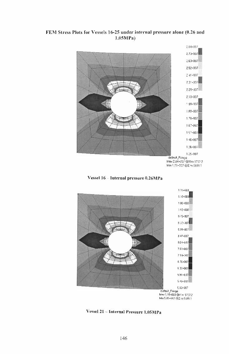
FEM Stress Plots for Vessels 16-25 under internal pressure alone (0.26 and 1.05MPa)
Vessel 16 - Internal pressure O.26MPa
2.84-007
2.73+0071
I·~ 2.63+007 . '
2.52+007
2.41 +007
231+0071
220+0071
2.10+007
199+0071
lB9+0071
1.78+0071
1.67+0071 1.57+007
146+0071
136+0071
1.25-007
Max 2.84.007 @Elm 5737.2 Min 1.25.007 @Elm 56991
1.15+008
1.10+0081
1.06+0081
1.02+008
9.75+007
932+0071
889,0071
8.47+00 7
8.04+0071
761+007.
719+007.
676+0071
633+0071
5.91+007.
54s+0071
5.05+007 nge '
Ma>: 1.15+008 @Elm 5737.2 Mm 5.05+007 @Elm 5699.1
Vessel 21 - Internal Pressure 1.05MPa
146

Vessel 17 - Internal Pressure O.26MPa
Vessel 22 - Internal Pressure 1.05MPa
147
3.38 +007
1 324+007
3.10+00711
2.96+007
2.82+007
268+0071
254+007l,i
240+007
226+0071
212+0071
198+00711
184+0071 1.70+007
156+0071 • 142+00711
1 2B+007 defaulLFringe
Max 3.38+007 @Elm 5983.2 Min [email protected]
1.37+008
131+0081
125+00811
1.20+008
1.14+008
10B+ooal
1 . 03+008~ 9.71 +007
9.14+0071
6.58+0071
8.01+0071
7.45+ 0071 6.88+007
632+0071
575+00711
5.19+007 defaulLFringe :
Max 1.37 +008 @Elrn 5963.2 Min 5.19+007 @Elrn 5945.1
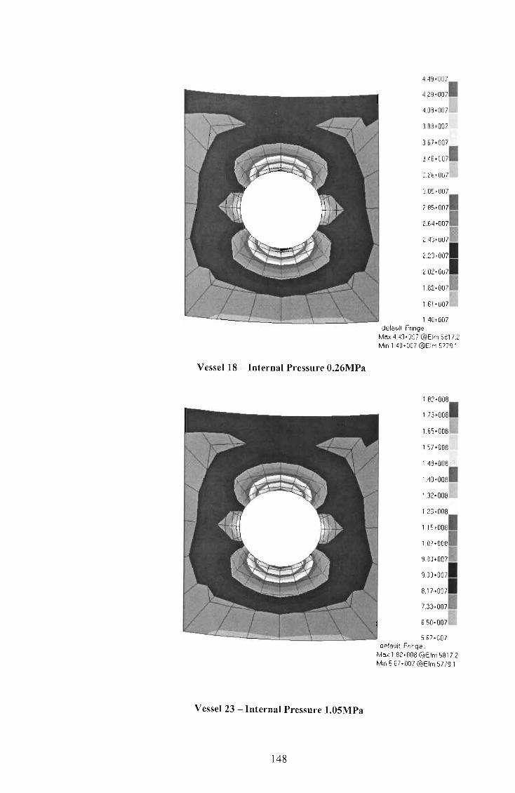
Vessel 18 - Internal Pressure O.26MPa
Vessel 23 - Internal Pressure 1.0SMPa
148
4.49 +007
4.29 +0071
4 0 8 ' 007~ 3.88 +007
1.40· 00 7 defoultfringe :
Ma;.: 4.49+007 @Elm 5817.2 Min [email protected]
1.82+008
1 73+0081
1.65+0081
1.57+008
1.48+008
14o+ooal 1.32+008
5.67+007 defoultFringe :
Ma;.: 182+008 @Elm 5817.2 Min 567+007 @Elm 5779.1

Vessel 19 - Internal Pressure O.26MPa
Vessel 24 - Internal Pressure 1.05MPa
149
5,77+007
548+0071
5,19-007
490+007
4.61-007
4.31+0071
4,02+007
3.73+007
3.44+0071
1 15+0071
2,86+00711
256+0071
2,27+0071
198+0071
1.69+00711
1.40+007 defoult_Fringe ;
Max 5,77+007 @Elm 59912 Min 1.40-007 @Elm 5953.1
2.33+008
1 2.21 +008
210+0061
1,98+00B
1.86+006
1.74+0001
1,62+00S[
5.65+007 defoullFnnge :
Max 2.33+008 @Elm 5991.2 Min 5.65+007 @Elm5953,1

Vessel 20 - Internal Pressure 0.26MPa
Vessel 25 - Internal Pressure 1.05MPa
150
6.62+007
627+0071 ~ t
5.93+007
5.58+007
5.24+007
4.89+0071
4.55+007
1.44+007 defaultJringe :
Max 6.62-007 @Elm 5643.2 Min 1.44+007 @Elm 5677.1
2.67+00B
2.53+0081
239+00all
225+008
2.12+00a
1.98+0061
1.84+00afi
1.7o+ooa
1.56+00al
1.42+006
1.28+00al
1.14+0061 1.00+00a
8.60+0071
7.21+0071i:
5.81+007 default_Fringe :
Max 2.67+008 @Elrn 5643.2 Min 581+007@Elm 5677.1

FEM Stress Plots for Vessels 16-25 under piping loads alone (SA SOL)
128+008
309+0081
289+00811
2.70+008
2.50+008
2.31 +0081 If< 2.11+00811!
1.92+008
172+0081
1.52+0081
133+0081
' ,13+0081
939+0071
7.43+0071
548+0071
3.52+007 defauitfringe .
Mo.-.: 126+008 @Elm 8781.2 Min 3.52+007 @Elm 8804.2
Vessels 16 and 21- SASOL Nozzle Loads only
3.71 +008
348+0081
3.25+00811
3.02+008
2.79+008
256+0081 "'"~
234+008.
2.11 +008
1.88+0081
1.65+0
1.42+008
1.19+008
9.64+007
736+0071 I~i
5.07+007.
2.79+007 defaullfring9 .
Mo.-.: 3.71 +008 @Elm 5577.2 Min 279-007 @Elm 5616.2
Vessels 17 and 22 - SASOL Nozzle Loads only
151

3.18.008
297+0081
277+oosD
2.56·006
2.36+008
2 15+0081
195+008'\~
1.02+007 deloult_Fringe ;
Mox 3.16+008 @Elm 5741.2 Min 102+007 @Elm 5828.3
Vessels 18 and 23 - SASOL Nozzle Loads only
2.72+008
1 2.55 .008
237+00811
2.20 ·008
2.03+008
185+0081
lS8+00aL
1.51 +008
1.34+0081
1.16+0081
9.90+0071
8.17+0071
6.44+0071
471+0071
298+0071
, .25+007 deloulLFringe ;
Mox 2.72+008 @Elm 5692.2 Min [email protected]
Vessels 19 and 24 - SASOL Nozzle Loads only
152

2.48 +008
232+0081
2.16+0oeL
201 +008
1.85+008
169+0081 M.'n
154+008 1;~~ 138+008
1,22+0081
1 06+0081
908+00711
7.51+0071 5,94+007
437+0071
280+0071
1 23+007 defeul~Fnnge :
Max 2, 46-008 @Elm 5644.2 Min 1.23-007 @Elm 5684.3
Vessels 20 and 25 - SASOL Nozzle Loads only
153
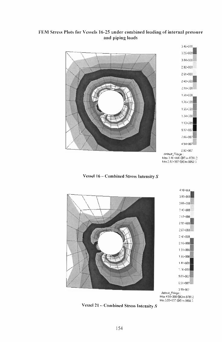
FEM Stress Plots for Vessels 16-25 under combined loading of internal pressure and piping loads
Vessel 16 - Combined Stress Intensity S
Vessel 21- Combined Stress Intensity S
154
3.46+008
325+0081
304+0081.:1
2.82+008
261 +008
240+0081
219+00S[
1.98+008
1.76+00sl
155+0081
1.34+0081
1.13+0081
9.17+0071
706+0071
4.94+0071
2.82+007 defaultfringe :
Ma:< 3.46+008 @Elm 8781.2 Mm 2.82+007 @Elm 8852 3
4.18+008
3.93+0081
3.68+0081
342+008
3.17+008
292+0081
2.67+008
2.42+008
216+0081
1.91+0081
166+0081
1.41+0081
1.16+0081
9.03+00711
6.51+00711
3.99+007 defaul1_Fringe :
Mox 418+006 @Elm 8781.2 Min 3.99+007 @Elm S866.3

Vessel 17 - Combined Stress Intensity S
Vessel 22 - Combined Stress Intensity S
155
3.12·008
2.14+008
1.90+00al
166+0081
1.42+0081
1.17+0081
9.31+0071
688+0071
11" 445+007 &;' .
2.02+007 defo.ulLFringe :
Max 3.84+006 @Elm 5577.2 Min 202.007 @Elm 5616.2
431+008
406+0081
380+0081
3.54+008
3.28+008
302+0081
ili' 2.76+001311
4.25+007 defo.ulLFringe :
Mo;.: 4.31 +008 @Elm 5577.2 Min 4.25+007 @Elm 5534.3

Vessel 18 - Combined Stress Intensity S
Vessel 23 - Combined Stress Intensity S
156
3.40 +006
318+0081
296+0086
2.74+008
2.52+008
2.30+0061
208+008!+j
1.66+006
1.42+00
1.20+00al
979+0071
759+0071
538+0071
3.18+0071
9.83+006 defoulLfringe ;
MI'IX 3.40+008 @Elm 57412 Min 9.83+006 @Elm 5779.2
4.14+008
389+0081
364+00all
339+008
3.14+00a
289+00el
264+00al:J
2.39+006
2 14+00al
189+0081
164+0081
1.39+0081 1.14+008
8.91+0071
6.41 +00711
3.91 +007 defaulLFringe .
MI'IX 4.14+008 @Elm 5741.2 Min 3 91 +007@Elm 5796.3

Vessel 19 - Combined Stress Intensity S
Vessel 24 - Combined Stress Intensity S
157
300+008
281 +00al
2.61 +008
2.42+008
2.23+008
204+0061
1.84+008
1.65+006
146+0081
126+0061
1.07+0081
8.78+0071 6.85+007
4.93+0071
300+0071
1.07+007 defaullJringe :
Max 300+008 @Elm 5693.2 Min [email protected]
4.13+006
1 3. 89+008
364+00811
3.40+008
3.15+008
291+0081
2.66+008
2.42+008
2 17+0081
1.93+0081
168+0081
1.44+0081 1.19+008
9.49+007
7.05+00711
4.60+007 default_Fringe :
Max 4.13+008 @Elm 5709.2 Min [email protected]

Vessel 20 - Combined Stress Intensity S
Vessel 25 - Combined Stress Intensity S
158
2.134+008
1 2.66+008
2.48+008lwl/
2.30+008
2.11+008
1.93+00al
1.75+008
1.57+008
139+0081
1.20+0081
102+00811
8.39+0071 6.57+007
4.75+0071
2.93+0071
1.1 1 +007 defaultFringe :
Mo:< 2.84+008 @Elm 5645.2 Min 1.1'1 +007 @Elm 5684.2
4.35+008
409+00sl
384+0081
3.59+008
3.33+008
3 06+00S~ 2.82+008
2.57+008
232+0081
2.06+00al
1.81 +0081
1.55+00al
1.30+008
105+0061
793+00711
5.39+007 delaultFringe :
Mo:< 4.35+008 @Elm 5661 .2 Min 5.39+007 @Elm 5701.2

Appendix C
159

Numerical Results for Vessels under External Pressure Vessel Do T CA L n E Per(W&T Per(ASME Per Per
s (mm (mm (mm (mm (GPa ) (MPa) ) (MPa) Von FEM ) ) ) ) ) Mises (MPa
(MPa ) )
1 2800 8 - 2000 8 200 0.318 0.330 0.329 0.385 2 2800 10 - 2000 8 200 0.555 0.570 0.583 0.667 3 2800 12 - 2000 8 200 0.875 0.900 0.950 1.046 4 2800 14 - 2000 7 200 1.287 1.320 1.347 1.557 5 2800 16 - 2000 7 200 1.797 1.800 1.900 2.126 6 2800 20 - 2000 7 200 3.139 2.532 3.459 3.695
7 1200 8 - 2000 4 200 1.132 1.140 1.202 1.323 8 1200 10 - 2000 4 200 1.978 1.980 2.032 2.397 9 1200 12 - 2000 4 200 3.120 3.090 3.215 3.570 10 1200 14 - 2000 4 200 4.587 3.960 4.822 5.104 11 1200 16 - 2000 4 200 6.405 4.830 6.923 7.069 12 1200 20 - 2000 4 200 11.189 6.641 12.88 12.53
9 3
160
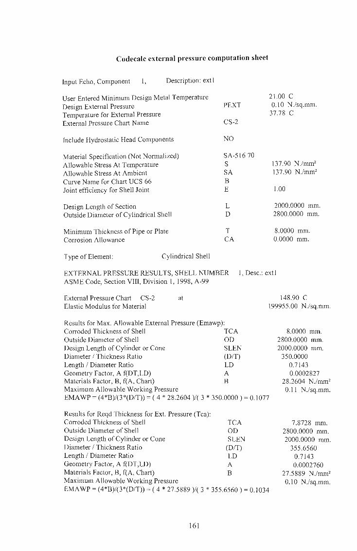
Codecalc external pressure computation sheet
Input Echo, Component 1, Description: extl
User Entered Minimum Design Metal Temperature Design External Pressure Temperature for External Pressure External Pressure Chart Name
Include Hydrostatic Head Components
Material Specification (Not Normalized) Allowable Stress At Temperature Allowable Stress At Ambient Curve Name for Chart UCS 66 Joint efficiency for Shell Joint
Design Length of Section Outside Diameter of Cylindrical Shell
Minimum Thickness of Pipe or Plate Corrosion Allowance
Type of Element: Cylindrical Shell
PEXT
CS-2
NO
SA-51670 S SA B E
L D
T CA
2l.00 C 0.10 N.lsq.mm.
37.78 C
137.90 N.lmm2
137.90 N .lmm2
l.00
2000.0000 mm. 2800.0000 mm.
8.0000 mm. 0.0000 mm.
EXTERNAL PRESSURE RESULTS, SHELL NUMBER 1, Desc.: extl ASME Code, Section VIII, Division 1, 1998, A-99
External Pressure Chart CS-2 Elastic Modulus for Material
at
Results for Max. Allowable External Pressure (Emawp): Corroded Thickness of Shell TCA Outside Diameter of Shell OD Design Length of Cylinder or Cone SLEN Diameter I Thickness Ratio (D/T) Length I Diameter Ratio LD Geometry Factor, A f(DT,LD) A Materials Factor, B, f(A, Chart) B Maximum Allowable Working Pressure
148.90 C 199955.00 N.lsq.mm.
8.0000 mm. 2800.0000 mm. 2000.0000 mm.
350.0000 0.7143 0.0002827
28.2604 N .lmm2
0.11 N.lsq.mm. EMAWP = (4*B)/(3*(D/T» = ( 4 * 28.2604 )/( 3 * 350.0000) = O.lO77
Results for Reqd Thickness for Ext. Pressure (Tca): Corroded Thickness of Shell Outside Diameter of Shell Design Length of Cylinder or Cone Diameter I Thickness Ratio Length I Diameter Ratio Geometry Factor, A f(DT,LD) Materials Factor, B, f(A, Chart) Maximum Allowable Working Pressure
TCA OD SLEN
(D/T) LD A B
EMAWP = (4*B)/(3*(D/T» = ( 4 * 27.5889 )/( 3 * 355.6560) = 0.lO34
161
7.8728 mm. 2800.0000 mm. 2000.0000 mm.
355.6560 0.7143 0.0002760
27.5889 N .lmm2
0.10 N.lsq.mm.

Results for Maximum Length Between Stiffeners (Slen): Corroded Thickness of Shell TCA Outside Diameter of Shell OD Design Length of Cylinder or Cone SLEN Diameter / Thickness Ratio (D/T) Length / Diameter Ratio LD Geometry Factor, A f(DT,LD) A Materials Factor, B, f(A, Chart) B Maximum Allowable Working Pressure
8.0000 mm. 2800.0000 mm. 2077.7944 mm. 350.0000
0.7421 0.0002716
27.1504 N.lmm2
0.10 N.lsq.mm. EMA WP = (4*B)/(3*(D/T)) = ( 4 * 27.1504 )/( 3 * 350.0000) = 0.1034
SUMMARY of EXTERNAL PRESSURE RESULTS: Allowable Pressure at Corroded thickness Required Pressure as entered by User Required Thickness including Corrosion all. Actual Thickness as entered by User Maximum Length for Thickness and Pressure Actual Length as entered by User
0.11 N.lsq.mm. 0.10 N.lsq.mm.
7.8728 mm. 8.0000 mm.
2077.794 mm. 2000.00 mm.
The CODECALC Program, (c) 1989-2000 by COADE Engineering Software
162

FEM Buckling analyses for Vessels 1-12 under external pressure and a 24"
Vessell - External Pressure O.lMPa
163
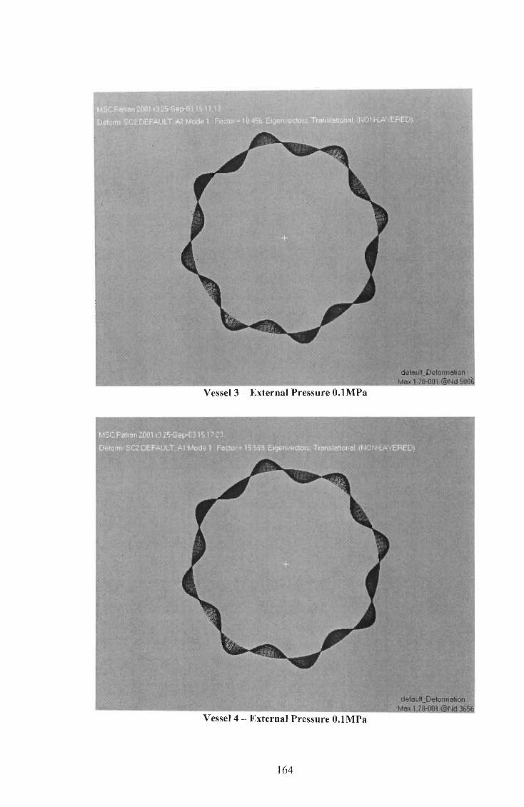
Vessel 3 - External Pressure O.lMPa
Vessel 4 - External Pressure O.lMPa
164

VesselS - External Pressure O.lMPa
Vessel 6 - External Pressure O.lMPa
165

Vessel 7 - External Pressure O.lMPa
Vessel 8 - External Pressure O.lMPa
166
xl!! defau't-Deformation<:
Ma>:: 1 <25-001 @)Nd 5106
defe.uICOeformation : Max 1.25-001 @>Nd5106

default_Deformation : Mex 1.61-001 ~Nd 3664
Vessel 9 - External Pressure O.lMPa
. . ..... default Deformation : " Mex1.61-001 ~Nd 5094
Vessel 10 - External Pressure O.lMPa
167

default Deformation : MO)( 1.61-001 {Q}Nd 5'094
Vessel 11 - External Pressure O.lMPa
defEl.!lILDeforme.\loo,;· . Max:l:61-001'{Q}Nd5094
Vessel 12 - External Pressure O.lMPa
168

FEM Stress Plots for Vessels 1-12 under external pressure and piping loads for a 24" Nozzle
6.35+008
594+0081
553+008
511 +008
4.70+008
428+0081
3.87-006
3.45 -008
304+0081
263+0081
2.21-00al
1.80+0081 1 38+006
968+0071
553+00711
1.39+007 defaulLFringe
Me;.: 6.35 -008 @Elm 5965.4 Min 1.39+007 (P}Elm 6024.3
Vessel 1 - Combined Stress Intensity (24" Nozzle)
4.46+008
4.17+0081
388+0081
1 59.008
3.30+008
3.01 +0081
2.72+008
2.43+008
2,15+0061 1,86+008
1.57+0081
128+0081
9,90+0071
7,01 +0071
412+0071
1.24+007 delauN_Fnnge ,
MO)( 4.46.008 @Elm 5818,2 Min 1 24+007 @Elm 5960.3
Vessel 2 - Combined Stress Intensity (24" Nozzle)
169

2.76+008
2.56+008
2.35+008
1 2.15+008
1.94+008
1.74+008
1.54+0081
1 133+008
113+0081
9.22+0071 7.18+007
513+0071
309+0071
1.05+007 default_Fringe :
Mo.:>: 3.17+008 @Elm 5984.2 Min 1.05+007 (O)Elm 6089.3
Vessel 3 - Combined Stress Intensity (24" Nozzle)
2.39+008
1 2.24·008
2.08+008
1.92·008
1.77+008
1.61+0061
1.46+00811
1.30+006
1.15+0081
9.91+0071
635+0071
680+0071
5.24+0071
368+0071
2.13+00711
5.72+006 defoulLFringe :
Mo.:>: 2.39+008 @Elm 5819.2 Min 5 72+006 @Elm 5959.3
Vessel 4 - Combined Stress Intensity (24" Nozzle)
170

1.82+008
17o+oosl
1.58+008
1.46+008
1.35+008
123+0081
1.11 +008
9.90+007
872+0071
7.53+0071
6.34+0071
5.16+0071
3.97+0071
279+0071
1.60+0071
4.15+006 defo.ulCFringe ;
M!IX 1.82+008 @Elm 5715.2 Min 4.15+006 @Elm 5889.3
VesselS - Combined Stress Intensity (24" Nozzle)
1.11+008
104+ 0081
964 +00711
8.94+007
8.23+007
752+0071
6.81+007.
6.10+007
5.40+0071
4.69+0071
3.96+007
327+0071
2.56+0071
1.86+0071
1.15+00711
440+006 default_Fringe :
M!IX 1.11 +008 @Elm 926.1 Min 4.40+006 @Elm 4052.3
Vessel 6 - Combined Stress Intensity (24" Nozzle)
171

4.29+008
1 4.01+008
3.72+00811
3.44+008
2.32+008
2.04+0081
1 1.76+00S
148+00sl
1.20+0081 9.16+007
635+0071
354+0071
7.31 +006 defau~fringe .
MO)( 4.29+006 @Elm 850.2 Min 7.31 +006 @)Elm 3842.3
Vessel 7 - Combined Stress Intensity (24" Nozzle)
2.62 +006
1 2.64+008
245+00sl
2.27+008
2.06+008
190+0081
171 +00811
1.53+008
1.35+00al
1.16+0081
977+0071
792+0071
6.08+0071
4.24+0071
2.39+00711
5.47+006 default_Fringe:
Ma:< 2.82+008 @Elm 3215.2 Min 5.47-006 @Elm 3477 3
Vessel 8 - Combined Stress Intensity (24" Nozzle)
172

2 08.008
1 1.94+008 fj
1.81+00Si!
1.54.008
140+00al
127+00S[!
1.13+008
9.96+0071
1 6.60+007
7.25+0071
589.0071 4.54+007
319+0071
183+0071
477·006 defOoultfringe :
Mo;.: 2.08+008 @Elm 3736.2 Min 4.77+006 (a)Elm 1490.3
Vessel 9 - Combined Stress Intensity (24" Nozzle)
1.54+008
1 1.44+008
134+00611
125+008'
1.15-006
105+00al
946+00711
8.48.007
749+0071
6.50+0071
5.51+0071
452+0071
3.53+0071
254+00711
154+0071
5.53+006 default_Fringe '
Max 1.54+006 @Elm 5726.2 Min 5.53+006 @Elm 5665.3
Vessel 10 - Combined Stress Intensity (24" Nozzle)
173

1.54+008
1.44+0061
134+0081
1.25+006
1.15+008
1.05+0081
9.48+007
8.46+007
7.49+0071
6.50+0071
5.51+0071
4.52+0071
353+0071
254+0071
154+00711
5.53+006 defaulLFringe :
Max 1.54+ 008 @Elm 5726.2 Min 5.53+006 @Elm 56853
Vessel 11 - Combined Stress Intensity (24" Nozzle)
7.14+007
668+0071
623+0071
5.78+007
532+007
487+0071
4.41+007[
396+007
3.50+0071
305+0071
259+00711
2.14+0071 1.68+007
123+0071
7.74+006
3.20+006 defaulLFringe :
Max 7.14+007 @Elm 5726.2 Min 3.20+006 @Elm 5885.3
Vessel 12 - Combined Stress Intensity (24" Nozzle)
174

FEM Deflection Plots for Vessels 1-6 under external pressure and piping loads for a 24" Nozzle
497-003.
4.66-003
4.34-003
402-003
371-003
339-003.
loa-Dol" 276-003
244-003.
213-003.
181-003.
1.50-003.
118-003
865-004
549-00411
2.33-004 defau1t-.Fringe .
Ma.>: 4.97-003 @Nd 7194 Min 2.33-004 @Nd 1120
Vessell - FEM Deflection (external pressure and 24" Nozzle)
3 15-003
295-003.
276-003.
256-003
237-003.
2.17-003
1 98-003
178-003
159-003.
139-003.
1 20-003.
101-003.
6.11-004.
6.16-004.
421 -004.
2.27-004 default-.Fringe :
Max 3.15-003 @Nd 6926 Min 2.27-004 @Nd 6998
Vessel 2 - FEM Deflection (external pressure and 24" Nozzle)
175
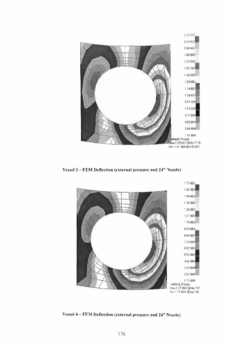
2.29-003
214-0031' 200-003
1.85-003
1.72-003
157-0031 ~~~
143-003~k~~
857-0
7.14-004
571-0041
428-00411
264-0041
Vessel 3 - FEM Deflection (external pressure and 24" Nozzle)
1.77-003
166-0031
1 1.54-003 %
1.43-003
1.32-003
1 1.21-003
1.10-0031
9.93-004
8.83-0041
7.72-004.
662-004.
552-0041
4.42-0041
3.31-0041
221-0041
111-004 defauiLFringe
Mox 1. 77-003 @Nd 157 Min 1.11-004@Nd 185
Vessel 4 - FEM Deflection (external pressure and 24" Nozzle)
176

139-003
1 130-003
1 ...
1.22-003 ..
113-003
1.04.003
1 950-004 ",,'
862-004.
7.74-004
685-0041
5.97-004.
509-0041
4.20-0041
332-0041
244-004.
1.55-0041
6.68-005 delaul\..Fringe .
Max 139-003 @Nd 193 Min 6.68-005 @Nd 329
Vessel 5 - FEM Deflection (external pressure and 24" Nozzle)
1.06-003
9.92-0041
925-0041
S .59-004 ~
7.93-004
1 7.26-004
660-0041
5.94-004
527-0041
1 4.61-G04
395-004.
328-0041
262-0041
196-0041
1.29-004.
6.28-005 defaul\..Fringe :
Max 106-003 @Nd 225 Min 6.28-005 @Nd 3551
Vessel 6 - FEM Deflection (external pressure and 24" Nozzle)
177

Appendix D
178

FEM Results for Vessels under External Pressure and Nozzle PipingLoads Vessel 1 2 3 4 5 6 7 8 9 10 11 12
s
Nozzl
es
4" Per' 0.36 0.64 1.01 1.50 2.08 3.62 1.02 1.92 3.15 4.70 6.61 11.85 (MPa) 2 0 4 0 0 6 3 6 6 0 7 3 8" Per' 0.30 0.56 0.90 1.34 1.90 3.37 0.88 1.61 2.64 4.02 5.77 10.52 (MP a) 6 0 0 7 3 9 1 2 5 0 0 3 12" Per' 0.27 0.50 0.81 1.22 1.74 3.11 0.78 1.49 2.45 3.70 5.29 9.560 (MPa) 9 4 8 8 3 6 9 0 2 9 1 16" Per' 0.25 0.47 0.76 1.15 1.63 2.93 0.55 1.18 2.13 3.35 4.86 8.927 (MPa) 7 1 6 2 8 9 0 3 1 4 7 20" Per' 0.22 0.43 0.72 1.10 1.57 2.83 0.39 0.83 1.52 2.51 3.86 7.705 (MPa) 5 6 5 2 5 8 4 0 0 9 8 24" Per' 0.18 0.37 0.64 1.02 1.48 2.73 0.32 0.66 1.21 2.01 3.10 6.312 (MPa) 1 0 9 1 8 4 0 9 7 3 2
179

FEM Buckling Analyses for Vessel 6 and Vessel 12 under external pressure and piping loads for the six nozzles
Vessel 6 - FEM Buckling Analysis 4" Nozzle
Vessel 6 - FEM Buckling Analysis 8" Nozzle
180

Vessel 6 - FEM Buckling Analysis 12" Nozzle
Vessel 6 - FEM Buckling Analysis 16" Nozzle
181

Vessel 6 - FEM Buckling Analysis 20" Nozzle
Vessel 6 - FEM Buckling Analysis 24" Nozzle
182

Vessel 12 - FEM Buckling Analysis 4" Nozzle
Vessel 12 - FEM Buckling Analysis 8" Nozzle
183
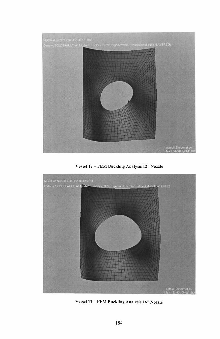
Vessel 12 - FEM Buckling Analysis 12" Nozzle
Vessel 12 - FEM Buckling Analysis 16" Nozzle
184

Vessel 12 - FEM Buckling Analysis 20" Nozzle
Vessel 12 - FEM Buckling Analysis 24" Nozzle
185

Relationships between the out-of-round stress and the WRC 107 maximum
25.0
20.0
_15.0 n:I a.. ~
Cl b 10.0 -
5.0
compressive stress for the 4", 8",12",16",20" and 24" nozzles
y = 3E_08x3.414
0.0 L-~~.......::::::::=_~ 80 120
30.0 '
I
25.0 j 20.0 1
-n:I a..
~ 15.0 I 10.0 j
5.0 J I
80 120
160 200 240 280 320
WRC 107 Maximum Compressive Stress (MPa)
4" Nozzle
160 200 240 280 320
WRC 107 Maximum Compressive Stress (MPa)
8" Nozzle
186
360 400
y = 4E_07x2.99
360 400

70.0
60.0
50.0
'iO 40.0 a.. ~
~ 30.0 l 20.0 ~
10.0 ~
~~:::::= 0.0 I
-
80
90.0 l 80.0 ~
70.0 1 60.0
~ 50.0 ~ ~ 40.0 1
30.0 ~
20.0 J
10.0 J
120 160 200 240 280 320
WRC 107 Maximum Compressive Stress (MPa)
12" Nozzle
0.0 ~ ........... ~::;::::::=- --,---------, 80 120 160 200 240 280 320
WRC 107 Maximum Compressive Stress (MPa)
16" Nozzle
187
y = 4E_06x2.755
360 400
y = 4E_06x2.815
360 400

120.0
100.0 y = 1 E_05x2.69
80.0
ca D.. ~ 60.0 -0 b
40.0 ~
20.0
0.0 ----,
80 120 160 200 240 280 320 360 400
WRC 107 Maximum Compressive Stress (MPa)
20" Nozzle
140.0 l
120.0 J y = 3E_05x2.5356
100.0 J
I - 80.0 l nI D..
~ 60.0 J 0
b
I 40.0 1
I 20.0 1
I 0.0 I
80 120 160 200 240 280 320 360 400
WRC 107 Maximum Compressive Stress (MPa)
24" Nozzle
188

Appendix E
189

Vessell(Chapter 3) FEM Plots and design calculations for external pressure and piping loads
Vessell (Table 3-4) - FEM Buckling Analysis (external pressure only)
190

Vessell (Table 3-4) - FEM Buckling Analysis (external pressure + 6" Nozzle)
Design of Pressure Vessels under External Pressure
and Nozzle Pi~ing Loads : user fi 11 in
ASME VIII Div 1 : UG-28
Do= 598mm
t= 14mm
CA= 3mm
L= 1000mm
E= 200000MPa
n= 3
Critical Buckling Pressure Pcr = 14.270MPa
Nozzle
Nozzle: 6 inch
, Calculation of Buckling Stress (jcr
(JUTS = 483MPa
WRC 107 = 287MPa
Out of Roundness Stress = 8MPa
A= 5.358mm
, G"cr = 121.3MPa Bolt
, G"cr = 148.5MPa FEM
191

Vessel 3(Chapter 3) FEM Plots and design calculations for external pressure and piping loads
Vessel 3 (Table 3-4) - FEM Buckling Analysis (external pressure only)
Vessel 3 (Table 3-4) - FEM Buckling Analysis (external pressure + 4" Nozzle)
192

Design of Pressure Vessels under External Pressure
and Nozzle Piping Loads : user fill in
ASME VIII Div 1 : UG-28
Do= 716mm
t= 8mm
CA= Omm
L= 800mm
E= 200000MPa
n= 5
Critical Buckling Pressure Pcr = 6.141MPa
Nozzle
Nozzle: 4 inch
Calculation of Buckling Stress (jcr'
(JUTS = 483MPa WRC 107 = 202.1MPa Out of Roundness Stress = 2.3MPa
A= 0.674 mm
, o-cr = 201.6MPa
, o-cr = 202.2MPa
193
Holt
FEM

Appendix F
194

Effects of External Piping Loads on a Pressure Vessel under External
Pressure
.a* a.a A MaharaJ ,C J von Klemperer , S Adall
aSchool of Mechanical Engineering, University of Natal , Durban, 4001 , South Africa
Abstract
This paper deals with the effects of external piping loads at the nozzle on cylindrical pressure
vessels under vacuum . It describes the various theoretical methods with regard to the design of
pressure vessels under external atmospheric pressure. An approach to the design of pressure
vessels, under the combined effect of external atmospheric pressure and piping loads at the
nozzle, is then explored . Numerical models, val idated by theory using the ASME (American
SOCiety of Mechanical Engineers) VIII Div 1 and 2 [1] Pressure Vessel Codes, are correlated
with that of numerical models generated by the finite element analysis software MSC PATRAN
[2].
Keywords: Piping loads; External atmospheric pressure; Finite element analysis
Nomenclature
(Jer critical buckling stress P er reduced critical buckling pressure
(Jmax maximum local stress KuTs ultimate tensile stress of material
(Jer reduced critical buckling stress A out -of -rou nd ness
P er critical buckling pressure Uo initial radial deviation
L unsupported length of vessel M total bending moment
Do outside diameter of vessel r cylinder outer radius
thickness of vessel 0 Et3
fl I . 'd' = ( 2 ) exura rlgl Ity 12 1- ,LL
,LL poison's ratio M ar out-of-round bending moment
n lobes of buckling (Jar out-of-round stress
E Young's Modulus of material r/J angle
1. Introduction
There are currently several well-known and widely-used procedures for predicting the structural
stability of pressure vessels under external pressure. However, effects of combined loads were
not investigated fully. In the present paper the combined effects of the external atmospheric
pressure and the piping loads at the nozzle are investigated.
195

·corresponding author (Tel : +27 31 2601225, Fax: +27 31 2603217; email: [email protected])
These combined effects could be catastrophic if not addressed properly, especially when the
stability of the structure is a crucial consideration , i.e. when buckling is a concern .
In unstable thin-walled vessels the imposition of an external force results in additional
deformation, which may not vanish upon the removal of the force. Greater forces induced by
piping loads at the nozzle cause greater deformations to occur [3,4], thereby rendering the
vessel more unstable. The design of the vessel must therefore be modified to include also the
effects of the piping loads at the nozzle. Expressions for the prediction of the critical buckling
pressure under external pressure alone were first derived by von Mises and later improved by
Windenburg and Trilling [3,5] . Currently, design engineers use the procedures provided in the
ASME Pressure Vessel Design Code to predict the critical buckling pressure of a pressure
vessel under external pressure. These expressions predict the general buckling behaviour of
the entire vessel.
The combined effect of external pressure and piping loads will result in local buckling occurring
at the shell-to-nozzle junction. The effects of nozzle loads cause increased stress
concentrations to occur at the shell-to-nozzle junction. Stresses in this region are thus greater
than the critical buckling stress for the vessel. This highly stressed region can result in local
buckling [6-9] . Fig . 1 illustrates local stresses at the shell-to-nozzle junction, where the critical
buckling stress O'er is exceeded . Since nozzle loads cause deviations in vessels [3,4], it can be
assumed that this has the same effect on the stability of a vessel as does a vessel with
geometric imperfections.
The collapse pressure of cylindrical vessels subjected to external pressure is dependent on the
final fabricated shape. Imperfections or out-of-roundness in cylindrical vessels reduce the
ability of these vessels to withstand buckling. Out-of-roundness (deflections caused by nozzle
loads) at the shell-to-nozzle junction, reduces the buckling strength of the vessel. This results in
stresses at this region, shown in Fig. 2, being much greater than the reduced buckling strength
O'e;, thus rendering the vessel more unstable.
2. Finite Element Models
The investigation of the theory and FEM (Finite Element Methods) critical buckling pressures
are based on the 6 vessels (typical large diameter vessels commonly used in industry) shown in
Table 1. Each of the above vessels (1 to 6) is analysed using a 24 inch (609.6mm outer
diameter) nozzle together with its corresponding loads. Figure 3 gives a representation of
nozzle loads with different orientations and typical values of these loads. The material
properties are obtained from ASME VIII Div 2 Part D, as shown in Table 2.
196

In the present study, two FEM models of the pressure vessels, which are generated using MSC
PATRAN, are considered . The first, Model A shown in Figure 4 [2], which is a circular cylinder
with no nozzle loads is used to correlate the FEM buckling pressures with the calculated
theoretical values. The second , Model B shown in Figure 5 [10,11], includes piping loads at the
shell-to-nozzle junction, and is used to determine the critical buckling pressure of the 6 vessels
mentioned above.
3. Design of Pressure Vessels under External Pressure
Several equations have been developed for the computation of the buckling pressure of vessels
under external pressure. The first and most accurate equations were derived by von Mises
[3,5]. Von Mises developed equations for vessels subjected to radial pressure only, as well as
for vessels subjected to both radial and axial pressure. The design of vessels subjected to
radial and axial pressure using the expression developed in Refs . [3,5], is deemed to be much
safer, viz.,
(1 )
Windenburg and Trilling [3,5] also derived an approximate equation given by
( J5/ 2
P = 2.42E i: er (1- 2)3/4 (JI/2
JI ~ _ 0.45 _ t_
Do Do
(2)
The number of lobes of buckling, n, is given by the equation.
(3)
Due to its simplicity, the expression given in eq. 2, is recommended in the ASME Code for the
design of vessels under external pressure. The ASME VIII Div 1 and 2 Code incorporates eq . 2
197

to create their procedures for the design of pressure vessels under external pressure. Table 3
shows the comparison between FEM critical buckling pressures and theoretical values using
Model A. Von Mises critical buckling pressures provide the best correlation with the FEM
values. The ASME values differ from the FEM values , due to safety factors included in the
ASME Code [1] design procedures. The FEM model can be confirmed by determining the lobes
of buckling for the vessels. Fig. 6 show the lobes of buckling for vessel 5, obtained from FEM
analyses. For vessel 5, the theoretical value of n, using eq . 3, is calculated as n = 7. Figure 6
also shows 7 lobes confirming the FEM results.
4. Design of Pressure Vessels under Eternal Pressure and Piping Loads
Results obtained using Model B are shown in Table 4. Critical buckling pressures for vessels 1
- 6, including nozzle loads, were determined by the FEM Model B. Table 4 indicates that
nozzle loads reduce the critical buckling pressure. The critical buckling stress of a vessel,
inclusive of nozzle loads, is calculated using the reduced buckling pressure given in Table 4.
As stated earlier, local buckling at the shell-to-nozzle junction occurs when the stresses induced
by both nozzle loads and external pressure exceed the critical buckling stress of the vessel.
Table 5 gives a comparison of the theoretical stresses at the shell-to-nozzle junction , calculated
using the WRC 107 [12] method and FEM, with the critical buckling stresses of the vessel. The
critical buckling stress of a vessel with no nozzle loads is calculated using the buckling pressure
generated by using eq. 2 given by Windenburg and Trilling [3 ,5] .
It can be seen from Table 5 that the stresses generated by the combined loading of nozzle
loads and external pressure (WRC 107 and FEM) exceed the critical buckling stresses for
vessels 1 - 5. The inclusion of nozzle loads reduce the critical stress (Windenburg & Trilling)
even further, which implies that severe local buckling will occur at the shell-to nozzle junction.
The local stress calculated for vessel 6 is much lower than the critical buckling stress (inclusive
of nozzle loads). The thickness of this vessel is 20mm, which implies that the vessel is much
stronger and the stress is therefore much lower.
Reduced critical buckling stresses, for vessels 1 - 6 subjected to both external pressure and
piping loads, have been achieved using FEM (Table 5). However, analytical results will also
have to be generated. The design of pressure vessels under external pressure and piping
loads at the nozzle requires the assumption that the piping loads cause deviations in the vessel,
which implies that the vessel can be treated as an out-of-round cylinder [3]. Analytical methods
have been developed to account for the effect of geometric imperfections in cylindrical shells
subjected to external pressure. Holt [13] developed a formula for the buckling pressure of a
vessel with an initial out-of-roundness, which is given by
198

I 2K UTS -
Do (4)
Eq. 4 was determined on the assumption that the initial out-of-roundness is similar in form to the
assumed buckling mode shape . This is not the case for vessels under external pressure and
external piping loads. A relationship between nozzle loads and eq. 4 has to be developed. To
develop this relationship one needs to take into account the fact that nozzle loads increase the
local stresses at the shell-to-nozzle junction . Geometric imperfections at localised areas also
increase stress concentrations. Timoshenko [14] studied the effects of cylinders and tubes with
initial noncircularity subjected to external pressure and developed a theory around this. The
most common form of noncircularity is that of an elliptical or oval shape. Using this kind of
imperfection the deviation caused by noncircularity could be shown to be [14] ,
(5)
Fig. 7 shows an imperfect cylinder as given in [14,15]. When an external pressure is applied,
an additional radial displacement U2 will occur. Timoshenko [14] determined that the deflection
caused by external pressure is given by the following higher order diferential equation :
(6)
This equation also applies to Fig. 7. Considering an elemental ring of unit width the
compressive force shown in Fig. 7 is given by F = pr . Thus the bending moment at any cross
section is equal to the compressive force multiplied by the total radial deviation Ut + U2
at this
cross section, viz.
M = pr(u2 + Uo cos2l/J) (7)
Substituting eq . 7 into eq . 6 and rearranging give :
(8)
The solution of eq. 8 is given by
199

(9)
Substituting eq . 9 into eq . 7 and taking the bending moment to be maximum at points r:::t and
~ = n, we obtain :
(10)
The compressive critical stress is obtained by converting M or to a stress :
(11)
Where Do =2r and Uo = A . The increased stress for an imperfect vessel can be determined
using eq. 11. Substituting A from eq. 4 into eq . 11 , one can determine a relationship between
the maximum compressive stress (nozzle loads only) and the maximum out-of round stress (eq .
11). The differences between these stresses is shown in Table 6.
Table 6 gives the stresses, for vessels 1 to 6, for the maximum compressive stress generated
by nozzle loads using WRC 107 and the maximum out-of-round stress calculated using eq. 11 .
The results indicate that out-of-round stresses and stresses generated by nozzle loads increase
the stress concentration at localised regions. Therefore, a relationship between the two
stresses can be developed . However, this relationship is for a 24" (609.6mm outer diameter)
nozzle. Further relationships for various other nozzles can be developed.
5. Conclusion
The effects of piping loads on pressure vessels under external pressure have been
investigated. Theoretical models have been generated and analysed and compared to results
obtained by the finite element software MSC PATRAN. The theoretical results for vessels under
external pressure alone coincide with the finite element values. For the effects of the piping
loads further finite element analyses were generated and the results indicated that these
vessels could be related to out-of-round cylinders. Out-of-roundness causes a reduction in the
buckling strength of the vessel thus making it unstable.
200

Procedures will have to be developed for the design of these vessels under piping loads at the
nozzle. This will involve the modification of the three major design parameters (diameter, length
and thickness) to ensure a much stronger vessel under buckling. The design engineer will have
to determine the critical buckling strength at the shell-to-nozzle junction. The research shows
that this can be achieved by determining, for various types of nozzles, relationships between
compressive stresses due to nozzle loads and stresses due to out-of-roundness. The out-of
round compressive stress will give an out-of-round value, which can be used in Holt's formula
to calculate the critical buckling pressure at the shell-to-nozzle junction. To prevent local
buckling from occurring, stresses induced in the shell due to external pressure and piping loads
should be within the calculated critical buckling stress of the shell-to-nozzle junction.
6. References
1. ASME. ASME Boiler and Pressure Vessel Code. Section VIII Div 1 and 2, 1980.
2. MSC PATRAN - Reference Manual. The McNeal Schwendler Corporation, 2001.
3. Bickell M.B., Ruiz C. Pressure Vessel Design and Analysis. Macmillan, 1967.
4. Chapuliot S., Moulin D., Plancq D. Mechanical Behaviour of a Branch Pipe Subjected to Out
of-Plane Bending Load . Journal of Pressure Vessel Technology, 2002;124:7-13.
5. Alien H.G., Bulson P.S. Background to Buckling. 1st Edition, McGraw-Hill Book Company,
USA, 1980.
6. Minjie C., Mark J., Hoist F.G., Rotter J.M. Buckling Strength Of Thin Cylindrical Shells Under
Localized Axial Compression. 15th ASCE Engineering Mechanics Conference, 2002.
7. Lagace PA Other Issues In Buckling/Structurallnstability, 2001 .
8. Walker P. Buckling of Cylinders With Local Loads Normal To The Shell. ABAQUS UK Users
Group Conference, 2001 .
9. Harvey J.F. Theory and Design of Pressure Vessels. P.E. van Nostrand Reinhold Company,
1985.
10. Schneider M.H. , Feldes R.J., Halcomb J.R. and Hoff C.C. Stability Analysis of Perfect and
Imperfect Cylinders using MSC Nastran Linear And Non-Linear Buckling. MSC World
User's Conference Proceedings, Paper No. 27, 1995.
11. Dahlgren F. NCSX-Vacuum Vessel Stress Analysis. Princeto University, 2002.
12. Winchman K.R., Hopper A.G ., Mershon J.L. Local Stresses in Spherical and Cylindrical
Shells due to External Loadings. Welding Research Council Bulletin 107, 1979.
13. Holt M. A Procedure for Determining the Allowable Out-of-Roundness for Vessels Under
External Pressure. Transactions of the ASME, 1952;74(7):1225-1230.
14. Timoshenko S.P., Gere J.M. Theory of Elastic Stability. Second Edition,McGraw-Hill
Book Company, 1961 .
15. Jawad M.H., Farr J.R. Structural Analysis and Design of Process Equipment.
John-Wiley and Sons, 1989.
201

Figure Captions
Figure 1 : Local Stresses exceeding Critical Buckling Stress
Figure 2 : Local Stresses exceeding reduced Critical Buckling Stress
Figure 3 : Nozzle Loads with orientations
Figure 4 : Model A
Figure 5 : Model B
Figure 6 : Buckled Vessel 5 - Model A
Figure 7 : Cylinder with Initial Ellipticity under External Pressure
Tables
Table 1 : Vessels for Theoretical and FEM Analysis
Table 2: Vessel Material Properties
Table 3 : Comparison of Buckling Pressures between Theory and FEM
Table 4: FEM Analyses for Vessels with Nozzle Loads
Table 5 : Comparison of Local and Critical Buckling Stresses at the shell-to-nozzle junction
Table 6 : Stress relationship between nozzle loads and out-of-roundness
202

external pressure + piping loads
1 1 1 1 external pressure external pressure
111 111 O"cr O"cr
O"max O"max
Figure 1 : Local Stresses exceeding Critical Buckling Stress
external pressure + piping loads
1 1 1 1 external pressure
111 __ 1 _ __ ______ _ L ...
O"max
, , , \
\
I I
, ,
external pressure
111 O"cr
I
_ .1.. - -- - ----- .1. -
O"max
Figure 2 : Local Stresses exceeding reduced Critical Buckling Stress
203

p
Nozzle Loads
p = 35500N
Mc = 16900Nmm
ML = 24800Nmm
Figure 3 : Nozzle Loads with orientations
Figure 4 : Model A
204

Figure 5 : Model B
Isometric view Top view
Figure 6: Buckled Vessel 5 - Model A
205

F = pr F = pr
p ) <
p
' __ """"-__ ..L-
/
Figure 7 : Cylinder with Initial Ellipticity under External Pressure
206
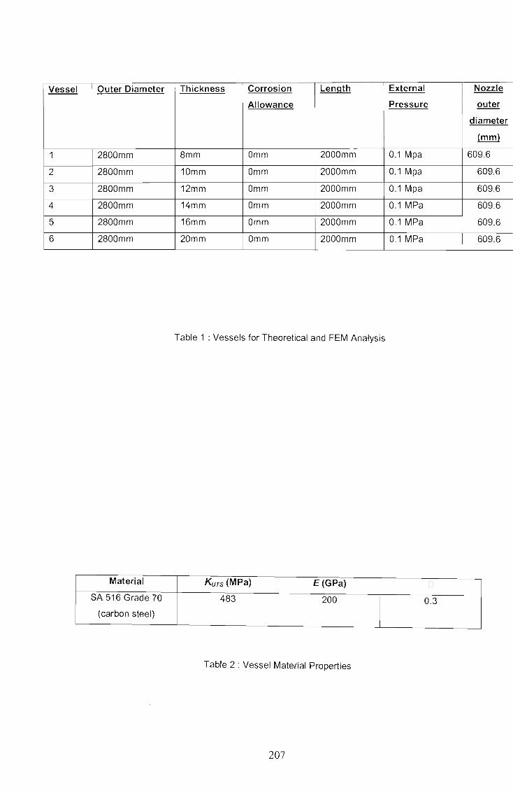
Vessel Outer Diameter Thickness Corrosion Length External Nozzle
Allowance Pressure outer
diameter
(mm)
1 2800mm 8mm Omm 2000mm 0.1 Mpa 609.6
2 2800mm 10mm Omm 2000mm 0.1 Mpa 609.6
3 2800mm 12mm Omm 2000mm 0.1 Mpa 609.6
4 2800mm 14mm Omm 2000mm 0.1 MPa 609.6
5 2800mm 16mm Omm 2000mm 0.1 MPa 609.6
6 2800mm 20mm Omm 2000mm 0.1 MPa 609.6
Table 1 : Vessels for Theoretical and FEM Analysis
Material KUTS (MPa) E (GPa) ['
SA 516 Grade 70 483 200 0.3 (carbon steel)
Table 2 : Vessel Material Properties
207

Vessel t/Do Buckling Pressure Mpa
ASME Windenburg & Von Mises MSC
Trilling PATRAN
1 0.0029 0.330 0.329 0.329 0.385
2 0.0036 0.570 0.577 0.583 0.667
3 0.0043 0.900 0.913 0.950 1.046
4 0.0050 1.320 1.347 1.347 1.557
5 0.0057 1.800 1.887 1.900 2.126
6 0.0071 2.532 3.316 3.459 3.695
Table 3: Comparison of Buckling Pressures between Theory and FEM
Vessel tlDo MSC PAT RAN MSC PAT RAN
Buckling Buckling Pressure
Pressure MPa - MPa - 24" Nozzle
no nozzle
1 0.0029 0.385 0.181
2 0.0036 0.667 0.370
3 0.0043 1.046 0.649
4 0.0050 1.557 1.021
5 0.0057 2.126 1.488
6 0.0071 3.695 2.734
Table 4 : FEM Analyses for Vessels with Nozzle Loads
208

Vessel tlDo Local Stresses - Nozzle Critical Buckling Stress
loads + External Pressure
WRC 107 FEM Windenburg Nozzle Loads
& Trilling- + External
no nozzle Pressure
1 0.0029 612.6 MPa 635 MPa 57.6 MPa 31 .7 MPa
2 0.0036 408.5 MPa 446 MPa 80.8 MPa 51 .8 MPa
3 0.0043 289.8 MPa 317 MPa 106.5 MPa 75.7 MPa
4 0.0050 217.3 MPa 239 MPa 134.7 MPa 102.1 MPa
5 0.0057 173.8 MPa 182 MPa 165.1 MPa 130.2 MPa
6 0.0071 118.2 MPa 111 MPa 232.1 MPa 191 .3 MPa
Table 5 : Comparison of Local and Critical Buckling Stresses at the shell-to-nozzle junction
Vessel MSC PATRAN MSC PATRAN Maximum Maximum out-
Buckling Buckling Compressive of-round
Pressure MPa Pressure MPa A- German Stress (WRC 107 - stress
- no nozzle - 24" Nozzle Code mm nozzle loads only) (formula 11)
MPa MPa
1 0.385 0.181 13.731 595.2 258.6
2 0.667 0.370 9.729 394.7 99.1
3 1.046 0.649 7.223 278.2 47.4
4 1.557 1.021 5.568 207.4 25.8
5 2.126 1.488 4.31 6 165.2 15.0
6 3.695 2.734 3.167 111.3 6.9
Table 6 : Stress relationship between nozzle loads and out-of-roundness
209

BIBLIOGRAPHY
[1] Timoshenko S. (1936) Theory oJ Elastic Stability. 1 sI Edition. McGraw-Hill Book
Company, USA.
[2] Siemon K. (1942) Pressure Vessel Manual. 51h Edition. Edwards Brothers Inc.
[3] Ho1t M. (1952) "A Procedure for Determining the Allowable Out-of-Roundness for Vessels
Under External Pressure." Transactions oJthe ASME. v. 74(7), p1225-l230.
[4] Galletly G.D. and Bart R (1956) "Effects of Boundary Conditions and Initial Out-of
Roundness on the Strength of Thin-Walled Cylinders Subjected to External Hydrostatic
Pressure." Journal oJ Applied Mechanics, p351-358.
[5] Donnell L.H. (1956) "Effects ofImperfections on Buckling of Thin Cylinders Under
External Pressure." Journal oJ Applied Mechanics. v. 23(4), p569-575 .
[6] Lunchick M.E. and Short RD.Jnr (1957) "Behaviour of Cylinders With Initial Shell
Deflection." Journal oJ Applied Mechanics. v. 24(4), p559-564.
[7] Timoshenko S. (1958) Strength oJ Materials Part 11 Advanced Theory and Problem. 3rd
Edition. V AN NOSTRAND REINHOLD COMPANY, New York.
[8] Flugge W. (1962) Stresses in Shells. 2nd Edition. Springer-VerJag, Germany.
[9] Bickel M.B. and Ruiz C. (1967) Pressure Vessel Design and Analysis. Macmillan.
[10] Arbocz J. (1974) "The Effects of Initial Imperfections on Shell Stability." Thin Shell
Structures: Theory, Experiment and Design. Edited by Fung Y.C. and Sechler E.E.
Pren ti ce-Hall.
[11] Cook RD. (1974) Concepts and Applications oJ Finite Element Analysis. John Wiley &
Sons Inc.
[12] Fung Y.C. and Sechler E.E. (1974) Thin Shell Structures: Theory, Experiment and
Design. Prentice-Hall, New Jersey.
210

[13] Kroenke W.C. (1974) "Classification of Finite Element Stresses According To ASME
Section III Stress Categories." Pressure Vessels and Piping Conference. The Pressure
Vessel and piping Division, ASME, p107-140.
[14] Gallagher R.H. (1975) Finite Element Analysis Fundamentals. Prentice-Hall Inc.
[15] Gwaltney R.C., Corum J.M., Bolt S.E. and Bryson J.W. (1976) "Experimental Stress
Analysis of Cylinder-to-Cylinder Shell Models and Comparisons With Theoretical
Predictions." Journal of Pressure Vessel Technology Transactions of the ASME. p283-290.
[16] Winchman K.R. , Hopper A.G. and Mershon J.L. (1979) Local Stresses in Spherical and
Cylindrical Shells due to External Loadings WRC Bulletin 107. Welding Research
Councill, New York.
[17] Allen H.G. and Bulson P.S. (1980) Background to Buckling. 1 sI Edition. McGraw-Hill
Book Company, USA
[18] Bednar H.H. (1981) Pressure Vessel Design Handbook. Van Nostrand Reinhold
Company, New York.
[19] Ugural AC. (1981) Stresses in plates and shells. McGraw-Hill Book Company, USA
[20] Harvey J.F. (1985) Theory and Design of Pressure Vessels . P.E. van Nostrand Reinhold
Company.
[21] Mershon J.L., Mokhtarian K., Ranjan G.V. and Rodabaugh E.C. (1987) Local Stresses
in Cylindrical Shells due to External Loadings WRC Bulletin 297. Welding Research
Councill, New York.
[22] Jawad M.H. and Farr lR. (1989) Structural Analysis and Design of Process Equipment.
John-Wi1ey and Sons.
[23] Primrn AB. and Stoneking J.E. (1989) "Accuracy Of The Finite Element Method For
Pressure VessellNozzle Design." The 1989 ASME Pressure Vessels and Piping Conferenc.
p3-9.
211

[24] Roche R.L. (1989) "Practical Procedure for Stress Classification." International Journal
of Pressure Vessels and Piping. v. (37), p27-44.
[25] Hechmer J.L. and Hollinger G.L. (1989) "Code Evaluation of 3D Stresses on a Plane."
Pressure Vessels and Piping Conference. pl-14.
[26] Ross C.T.F. (1990) Pressure Vessels under External Pressure Statics and Dynamics.
E1sevier Science Publishers Ltd.
[27] Sana1 Z. (1992) "Finite element analysis of discontinuity stresses at header-nozzle
intersections of plate-fin heat exchangers." i" International Conference on Pressure
Vessel Technology. Reports on science and Technology, p 1-6.
[28] Miller C.D. (1995) "The Effect of Initial Imperfections on the Buckling of Cylinders
Subjected to External Pressure." Pressure Vessel Research Council. pl-18.
[29] Schneider M.H., Feldes RJ., Halcomb J.R and Hoff C.C., (1995) "Stability Analysis
of Perfect and Imperfect Cylinders using MSC Nastran Linear And Non-Linear
Buckling." MSC World User's Conference Proceedings. Paper No. 27.
[30] Hechmer J.L. and Hollinger G.L. (1995) Summary Report - PVRC Project Three
Dimensional Stress Criteria. Pressure Vessel and Research Council. p 1-22.
[31] Benham P.P., Crawford RJ. and Armstrong C.G. (1996) Mechanics of Engineering
Materials. 2nd Edition. Longman, UK.
[32] Chao R. (1996) Local Stresses in Pressure Vessels Due to Internal Pressure and Nozzle
Loadings. Carmagen Engineering Report. Carmagen Engineering Inc.
[33] Gere J.M. and Timoshenko S.P. (1997) Mechanics of Materials. 4th Edition. PWS
Publishing Company, New York.
[34] ASME (1998) Rules for Construction of Pressure Vessels. ASME Boiler and Pressure
Vessel Code, Section VIII Div 1 and 2.
[35] MSC PATRAN - Reference Manual (200 I). The McNeal Schwendler Corporation.
212

[36] Singh M. and Diehl D. (2001) Modelling of Internal Pressure and Thrust Load on Nozzles
using WRC 368. COADE Mechanical Engineering News.
[37] Walker P. (2001) "Buckling of Cylinders With Local Loads Normal To The Shell."
ABAQUS UK Users Group Conference. pI-I!.
[38] Lagace P.A.(200l) Other Issues In Buckling/Structural Instability. Massachusetts Institute
of Technology.
[39] Minjie c., Mark J., Hoist F.G. and Rotter lM. (2002) "Buckling Strength Of Thin
Cylindrical Shells Under Localized Axial Compression." 15th ASCE Engineering
Mechanics Conference. p 1-8.
[40] Chapuliot S., Moulin D. and Plancq D. (2002) "Mechanical Behaviour of a Branch Pipe
Subjected to Out-of-Plane Bending Load." Journal of Pressure Vessel Technology,
Transactions of the ASME. v. 124, p7-13.
[41] Dahlgren F. (2002) NCSX-Vacuum Vessel Stress Analysis, Princeton University.
213