Embed Size (px)
Citation preview
A Class of Error-Locating Codes for Byte-Organized Memory Systems
Eiji Fujiwara, Senior Member, IEEE, and Masato Kitakami, Student Member, IEEE
Abstract-Error-locating codes (EL codes), first proposed by J. K. Wolf and B. Elspas in 1963, have the potential to be used to identify the faulty module for fault isolation and reconfiguration in fault-tolerant computer systems. This paper proposes a new class of EL codes suitable for memory systems organized with 6-bit ( b 2 2) byte-organized semiconductor memory chips that are mounted on memory cards each having B-bit width. The proposed linear code, called the S,/,EL code, identifies erro- neous memory card locations containing a faulty byte-organized chip. Another linear code proposed in this paper, the SEC- S,/ , EL code, corrects single-bit errors induced by alpha part- cles and, for byte errors, it locates erroneous card positions containing a faulty chip. This paper describes design methods of the proposed codes and shows an evaluation of the decoding hardware and the error detection capabilities.
Index Terms-Error-control codes, error-locating codes, byte- organized memory chips, S b / , EL codes, SEC-s,,, EL codes
I. INTRODUCTION
RROR control codes are now successfully applied to E memory systems in order to improve system reliabil- ity [ll. In particular, single-bit error correcting and dou- ble-bit error detecting (SEC-DED) codes [2] are widely used in semiconductor memory systems organized in a one-bit per chip manner. Recently, some systems have adopted a b-bit per chip organization, where b 2 2. A chip failure in these systems causes the word read-out to have a 6-bit length, called byte, in error. Therefore, b-bit byte error correcting/detecting codes [l], [31, [41 have been used extensively in recent high-speed memories.
Another important error-control function-error Zoca- tion-lying midway between the functions of error correc- tion and error detection was proposed by J. K. Wolf and B. Elspas in 1963 [5]. The received word is regarded as being divided into mutually exclusive blocks. This class of linear codes indicates which blocks are in error, without permitting the precise determination of erroneous digit positions within each block. Code construction methods for this type of code were proposed by several researchers [6]-[9]. The codes referred to as error-locating codes (EL codes) were originally proposed for use in efficient re-
Manuscript received August 16, 1993; revised September 8, 1994. This work was presented at the 23rd Annual International Symposium on Fault Tolerant Computing (FTCS-231, Toulouse, France, June 1993.
The authors are with the Department of Computer Science, Tokyo Institute of Technology, Tokyo 152, Japan.
IEEE Log Number 9406313.
transmission in communication systems [5], but have not been proposed for use in computer memory systems [lo] until now.
In general, a semiconductor memory module has a hierarchical organization consisting of memory cards on which memory chips are mounted. The memory card on which b-bit byte-organized RAM chips are mounted pro- vides data output having B-bit length, where B is a multiple of b. The predominant errors in byte-organized memory chips are soft errors, induced by alpha particles, which are apt to manifest themselves as single bit errors.
Under these situations, this paper proposes a new class of EL codes applicable to byte-organized memory systems. The proposed codes, S,,, EL codes, indicate erroneous card locations containing a faulty byte-organized chip. Another set of proposed codes, SEC-S,,, EL codes, cor- rects single bit errors mainly induced by alpha particles and, for byte errors, locates erroneous card positions containing a faulty chip. This type of code can effectively be applied to byte-organized memory systems in which an erroneous memory card is located by the code and then switched to a spare one. Therefore, it can be successfully used for fault isolation and reconfiguration in fault- tolerant systems.
This paper includes five sections. The work done by J. K. Wolf and B. Elspas is briefly described in Section I1 as an introduction to EL codes. Section I11 focuses on code design methods for a new class of error locating codes, and Section IV provides an evaluation of the proposed SEC - Sh,B EL codes from the perspectives of decoding complexity, error detection capability, and bounds on re- dundancy. Section V contains the conclusions.
11. ERROR-LOCATING CODES In the codes proposed by J. K. Wolf and B. Elspas [51,
the codeword is subdivided into s distinct bytes, each having b-bit length. This EL code detects e( < b ) or fewer errors, all occurring within a single byte, and identifies that byte. We call this code S,EL code. Let E,(E,) be the set of e or fewer errors occurring within the i(j)th byte. This code must satisfy the following relation:
forVe, E E,,Ve, E E,,i # j . The number of check-bits r is bounded from below by
e , H T # e,HT # o
r 2 log, 1 + s where [x] is the smallest integer which is not less than x.
'::: i:ji 0018-9448/94$04.00 0 1994 IEEE
1858
- 10001 01001 00101 0001 1 11000 10100 10010 10001 -
IEEE TRANSACTIONS ON INFORMATION THEORY, VOL. 40, NO. 6, NOVEMBER 1994
In general, the EL code is derived from the tensor product of the parity-check matrices [6].
Definition 2.1 [61, [7]: Let the matrices X = (x,,) and Y = (y , , ) be an a X b matrix and a c X d matrix, respec- tively. The matrix 2, defined as the tensorproduct of X and Y , is the ac x bd matrix given by
X l b Y
Z = X @ Y = r1;y :1' : 1. 0
XalY ... x a b y
Let H , be the parity-check matrix for a binary (b , b - p ) linear code C, that detects the class of errors E,. Let H , be the parity-check matrix for a nonbinary (s, s - m) linear code C, with symbols from G F (2 P ) , which corrects the class of errors E,. Finally, let C be the binary (bs, bs - p m ) linear code with parity-check matrix H given by
H = Hc @ H,.
Theorem 2.1 [61: If 1) all binary byte errors correspond- ing to the erroneous bytes are within class E,; and if 2) the erroneous bytes form a pattern of errors over G F (2 ") that falls in class E,, then, code C detects the errors and
If C, is an e-bit error detecting code and C, is a single-symbol error correcting code, then C is an S,EL code.
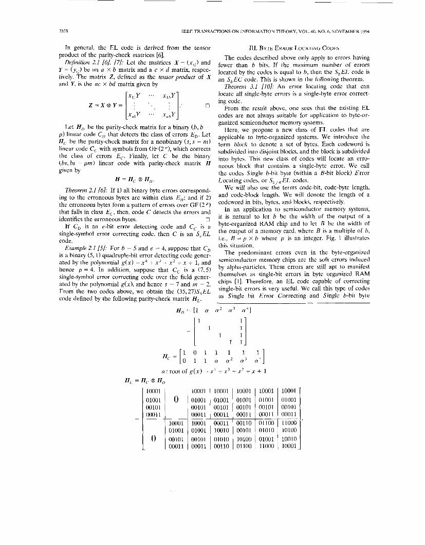
Example 2.1 [51: For b = 5 and e = 4, suppose that C, is a binary (5,l) quadruple-bit error detecting code gener- ated by the polynomial g(x) = x4 + x 3 + x 2 + x + 1, and hence p = 4. In addition, suppose that C, is a (7,5) single-symbol error correcting code over the field gener- ated by the polynomial g ( x ) , and hence s = 7 and m = 2. From the two codes above, we obtain the (35,27)S4EL code defined by the following parity-check matrix HL.
identifies the erroneous bytes. 0
rrI. BYTE ERROR LOCATING CODES
The codes described above only apply to errors having fewer than b bits. If the maximum number of errors located by the codes is equal to b, then the S,EL code is an S, E C code. This is shown in the following theorem.
Theorem 3.1 [lo]: An error locating code that can locate all single-byte errors is a single-byte error correct- ing code.
From the result above, one sees that the existing EL codes are not always suitable for application to byte-or- ganized semiconductor memory systems.
Here, we propose a new class of EL codes that are applicable to byte-organized systems. We introduce the term block to denote a set of bytes. Each codeword is subdivided into disjoint blocks, and the block is subdivided into bytes. This new class of codes will locate an erro- neous block that contains a single-byte error. We call the codes Single b-bit byte (within a B-bit block) Error Locating codes, or Sb,B EL codes.
We will also use the terms code-bit, code-byte length, and code-block length. We will denote the length of a codeword in bits, bytes, and blocks, respectively.
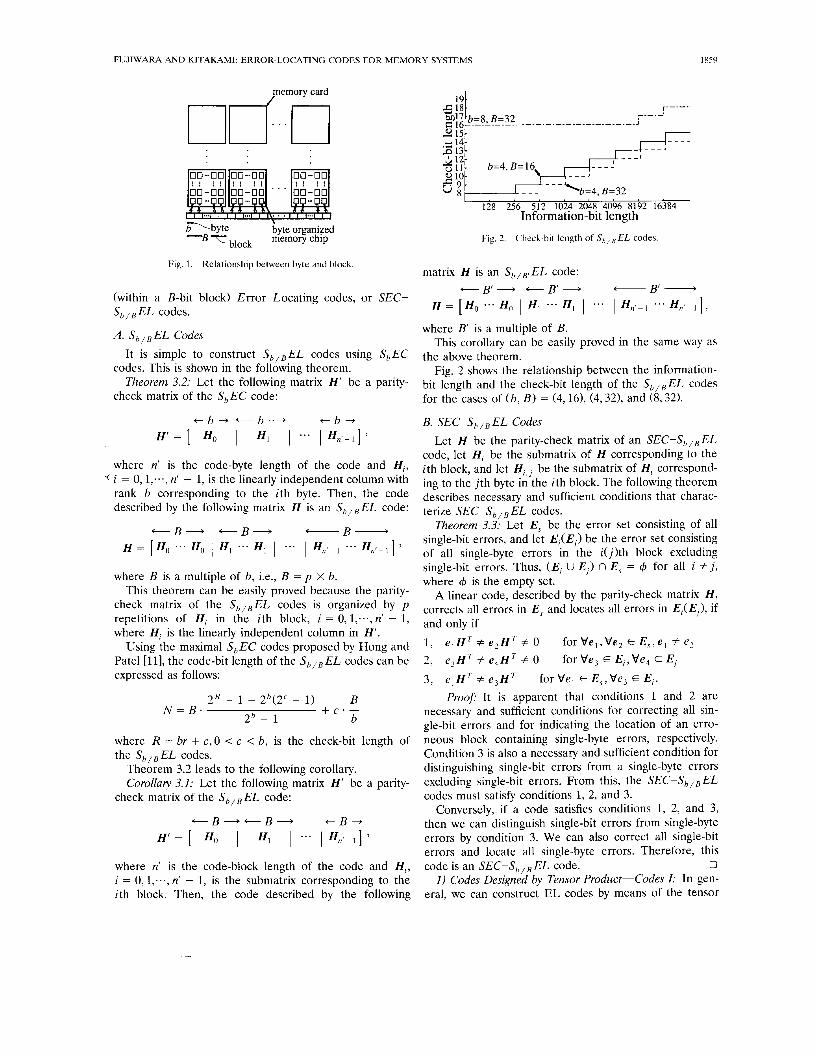
In an application to semiconductor memory systems, it is natural to let b be the width of the output of a byte-organized RAM chip and to let B be the width of the output of a memory card, where B is a multiple of b, i.e., B = p X b where p is an integer. Fig. 1 illustrates this situation.
The predominant errors even in the byte-organized semiconductor memory chips are the soft errors induced by alpha-particles. These errors are still apt to manifest themselves as single-bit errors in byte organized RAM chips [l]. Therefore, an EL code capable of correcting single-bit errors is very useful. We call this type of codes as Single bit Error Correcting and Single b-bit byte
a : root of g(x) = x 4 + x 3 + x 2 + x + 1 HL = H , @ H ,
10001
00101 0001 1
1000 1 01001
0 00101 + 0001 1
10001 10001 01001 01001 00101 00101 00011 00011 10001 00011 01001 10010 00101 01010 + 00011 00110
10001 10001 01001 01001 00101 00101 00011 00011 00110 01100 00101 01010 10100 01001 + 01100 11000
FUJIWARA AND KITAKAMI: ERROR-LOCATING CODES FOR MEMORY SYSTEMS 1859
pemory card
\ -byte c byte organized
B TTblock memory chip
191
128 256 512 102p 2048 4096 8192 16384 Information-bit length
Fig. 2. Check-bit length of Sh,"EL codes.
Fig. 1. Relationship between byte and block. matrix H is an S,,,,EL code:
+ B r + + B r + B' - (within a B-bit block) Error Locating codes, or SEC-
H = [ H , * * * H,, I H , ... HI 1 ... I H,+, ... H n , - l ] , sb , , E L codes. where B' is a multiple of B.
This corollary can be easily proved in the same way as the above theorem.
Fig. 2 shows the relationship between the information- bit length and the check-bit length of the sb,,EL codes for the cases of ( b , B) = (4,16), (4,321, and (8,321.
A. S,, , E L Codes
codes. This is shown in the following theorem.
check matrix of the S,EC code:
It iS Simple to Construct S,,,EL codes using S,EC
Theorem 3.2: Let the following matrix H' be a parity-
where n' is the code-byte length of the code and H , , i = 0, l;.., n' - 1, is the linearly independent column with rank b corresponding to the ith byte. Then, the code described by the following matrix H is an S,,,EL code:
+B+ + B + -B- H = [ H , ... H , I H I H , 1 e * * I H,,,- , * * * H,+ 7
where B is a multiple of b, i.e., B = p X b. This theorem can be easily proved because the parity-
check matrix of the S,,,EL codes is organized by p repetitions of H, in the ith block, i = 0, l,..., n' - 1, where H, is the linearly independent column in H' .
Using the maximal S,EC codes proposed by Hong and Pate1 [ll], the code-bit length of the S,,,EL codes can be expressed as follows:
2 R - 1 - 2,(2' - 1) 2, - 1
where R = br + c,O 5 c < b, is the check-bit length of the S h I B E L codes.
B + C ' - b
N = B .
Theorem 3.2 leads to the following corollary. Corollaly 3.1: Let the following matrix H' be a parity-
check matrix of the S,,,EL code:
c B + c B + + B - H' = [ HO I I ... I Hnt-11 7
where n' is the code-block length of the code and H, , i = 0, l;.., n' - 1, is the submatrix corresponding to the ith block. Then, the code described by the following
B. SEC-S,, , E L Codes Let H be the parity-check matrix of an SEC-S,,,EL
code, let H, be the submatrix of H corresponding to the ith block, and let H , , , be the submatrix of H, correspond- ing to the j th byte in the ith block. The following theorem describes necessary and sufficient conditions that charac- terize SEC-S,,, E L codes.
Theorem 3.3: Let E, be the error set consisting of all single-bit errors, and let E,(E,) be the error set consisting of all single-byte errors in the i(j)th block excluding single-bit errors. Thus, ( E , U E,) n E, = 4 for all i # j , where 4 is the empty set.
A linear code, described by the parity-check matrix H , corrects all errors in E, and locates all errors in E,(E,), if and only if
1, 2, 3, e , H T # e ,HT for V e , E E,,Ve, E E , .
Proof: It is apparent that conditions 1 and 2 are necessary and sufficient conditions for correcting all sin- gle-bit errors and for indicating the location of an erro- neous block containing single-byte errors, respectively. Condition 3 is also a necessary and sufficient condition for distinguishing single-bit errors from a single-byte errors excluding single-bit errors. From this, the SEC-S, ,, E L codes must satisfy conditions 1, 2, and 3.
Conversely, if a code satisfies conditions 1, 2, and 3, then we can distinguish single-bit errors from single-byte errors by condition 3. We can also correct all single-bit errors and locate all single-byte errors. Therefore, this
0 1) Codes Designed by Tensor Product-Codes I: In gen-
eral, we can construct EL codes by means of the tensor
e , H T # e ,HT # 0 e,HT # e,HT # 0
forVe,,Ve, E E, ,e , # e , for Ve, E E,,Ve, E E,
code is an SEC-S,,, EL code.
1860 IEEE TRANSACTIONS ON INFORMATION THEORY, VOL. 40, NO. 6, NOVEMBER 1994
product of two codes, one being an error correcting code and the other an error detecting code [6], [7], as was mentioned in Section 11. This method can also be applied to the construction of SEC-Sb,,EL codes by using a single-bit error correcting and single b-bit byte error detecting code, or an SEC-S,ED code [l], [12], and a single b-bit byte error correcting code, or an S, EC code [I].
Theorem 3.4: The code described by the following ma- trix H is an sEc-sb,,EL code:
H = Hi, 8 H:
= [HA 1 Hi I *.. 1 H(N/B)-I] 8 Hi = [ H h . Hi 1 Hi . H i 1 - e * I HiNlB)- . H i ]
where, again, 8 represents tensor product, B = p X b, N is the code-bit length of the sEC-s,,,EL code, HL, is the parity-check matrix of the S,,EC code, H i is the parity-check matrix of the ( B , B - b')SEC-S,ED codes, and H,' is the submatrix of HL,, corresponding to the ith byte.
Pro08 Because the binary columns of H are distinct, condition 1 indicated in Theorem 3.3 is satisfied.
The syndrome resulting from any single-byte error in the ith block is different from that in the j th block for i # j because each column in H, is determined by the product of Hl' by I?:. Hence, condition 2 is satisfied.
In general, every H,' includes the identity matrix I,, [ll, and therefore every H, has H: as a column element. This implies that the syndrome resulting from any single-bit error is different than that resulting from any single-byte error excluding single-bit errors. Based on this and condi- tion 2, condition 3 in Theorem 3.3 is satisfied.
From Theorem 3.3 above, it follows that the code 0
Example 3.1: For b = 4 and b' = 5, the following shows described by H is an SEC-S,,,EL code.
the S,EC code, described by the matrix HL,:
HA, = [HA 1 Hi I Hi I Hi 1 . - * I Hi?]
where T5 is a primitive element in GF(2'1, and 0, and I , are the zero element and identity element in G F (2'1, respectively.
Let H i be the parity-check matrix of the (12,7) SEC- S,ED code having b' = 5 check bits [12].
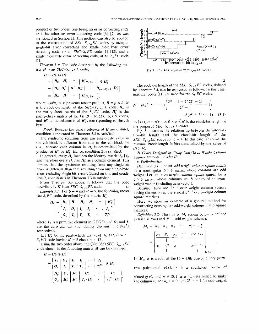
Using the two codes above, the (396,386) SEC-S,,,, EL code shown in the following matrix H can be obtained.
H = HL, 8 H i
Information-bit length
Fig. 3. Check-bit length of SEC-S,,,EL codes I.
0 The code-bit length of the SEC-S,,, EL codes, defined
by Theorem 3.4, can be expressed as follows. In this case, maximal codes [ l l ] are used for the S,,EC codes.
+ b(2b '+c-b+1 - 1). (3.1)
In (3.1), R = b'r + c, 0 I c < b' is the check-bit length of the proposed SEC-S,,, EL codes.
Fig. 3 illustrates the relationship between the informa- tion-bit length and the check-bit length of the SEC-S,,,EL codes for b = 4. In this case, B shows the maximal block length in bits determined by the value of b'( > b).
2) Codes Designed by Using Odd/Euen- Weight Column Squares Matrices-Codes II:
Preliminaries: Definition 3.1: Let an odd-weight column square matrix
be a nonsingular b x b matrix whose columns are odd weight. Let an even-weight column square matrix be a b X b matrix whose columns are b copies of an even- weight vector (including zero vector).
even-weight column vectors having dimension b, there exist 2'- even-weight column square matrices.
Here, we show an example of a general method for constructing nonsingular odd-weight column b X b square
Because there are 2,-
matrices.
to have b rows and 2'- ' odd-weight columns. Definition 3.2: The matrix Mb shown below
a 2 h - l - 1 ] Mb = [ao a2 a2 ' * '
is defined
Z b - I
In Mb, a is a root of the (b - 11th degree binary primi-
tive polynomial g(x), a i is a coefficient vector of
x'mod g(x), and pi E (0,l) is a bit determined to make the column vector a; , i = 0, l;.., 2,-' - 1, be odd-weight.
I
I
FUJIWARA AND KITAKAMI: ERROR-LOCATING CODES FOR MEMORY SYSTEMS 1861
Lemma 3.1: The following shows a nonsingular odd- weight column square matrix, generated from any consec- utive b column vectors in the matrix Mb:
where i, = i + j m 0 d 2 ~ - l , and 0 5 j 5 b - 1. Proof
1) If the matrix A , includes a column vector a,, =
(100 ... 0lT, then the ( b - 1) X ( b - 1) matrix excluding both a , and the first row from A , is a companion matrix that is nonsingular. Even if the column o of the lower part of a, , i.e., the zero vector having dimension ( b - 11, is appended to the nonsingular matrix, the summation of these columns including the column o cannot make a zero vector. Thus, A , is a nonsingular matrix.
2) If the matrix A , does not include a column vector ao, then the matrix excluding the first row has b column vectors of a' , a,+'; .- , and a '+b- ' . We assume that the summation of some (not necessarily all) column vectors in A , makes a zero vector. Because the summa- tion always includes two column vectors, a' and a'+'- ', the following equation is valid.
0, + ... f a , + b - 1 =
that is,
1 + ... _ t a b - ' = 0 (3.2)
The left-hand side of (3.2) is not necessarily the summa- tion of all elements of ai's for j = 0, l;.., b - 1. Equa- tion (3.2) states that a is a root of the binary polynomial of degree b - 1, say g(x1; therefore, g(x) is a multiple of the minimum polynomial [ l ] of a. Because (Y is a primi- tive element of GF(2b-1), the degree of the minimum polynomial of a is ( b - 1). These imply that g(x1 is the minimum polynomial of a and is irreducible. The number of nonzero coefficients of the binary irreducible polyno- mial g ( x ) is odd; therefore, the summation of an odd number of ai's, j = 0, l,..., b - 1, equals zero. Because all column vectors of A , are odd weight, the summation of an odd number of these columns cannot yield zero vec- tors. This contradicts the assumption. Therefore, A , is nonsingular.
Based on the argument above, A , has been proved to
From this lemma, we can obtain 2'-' nonsingular odd-
Example 3.2: For b = 4, we obtain the following odd-
be nonsingular. 0
weight column square matrices.
weight column matrix M4.
1. 1 0 0 0 1 1 0 1 0 1 0 0 1 0 1 1 0 0 1 0 1 1 1 0 0 0 0 1 0 1 1 1
M 4 = [ In this M 4 , the ith column vector, excluding the top element, is equal to the binary expression of x f mod g ( x ) = x3 + x + 1, for i = 1,2,-.., 7. The zero vector is given in the first column for i = 0.
Based on this, eight nonsingular odd-weight 4 X 4 square matrices, A , , A ' ; . . , A , , can be obtained. The fol- lowing shows A , as an example.
L l l l O ]
Construction of the Parity-Check Matrices: Let A and B be the sets of the odd-weight column square matrices and the even-weight column square matrices, respectively. The following lemma provides the basic idea of the new code design method.
Lemma 3.2: Consider the following two different vec- tors each having degree r , i.e., Q and Q', that are con- structed from the elements of the even-weight column square matrices and the odd-weight column square matri- ces, i.e., Q,, Ql, E A U B for j = 0, l;.-,r - 1. In each vector, there exists at least one matrix included in A .
We assume that the ith elements in Q and Q', i.e., Q, and Q:, respectively, are different square matrices. In other words, Q , is an odd-weight column square matrix and Q: is an even-weight column square matrix, or vice versa. Then any summation of binary column vectors in Q pro- duces a different result than that given by any summation of binary column vectors in Q'.
Proof Let s and sf, each having r b-tuples, be the results of the summation of column vectors in Q and Qf, respectively.
Without loss of generality, Q, and Q: can be regarded as the odd-weight column square matrix and the even- weight column square matrix, respectively. Assume s, = s:; then s is the vector resulting from the summation of an even number of columns in Q , and sf is that resulting from the summation of odd number of columns in Q'. There exists an odd-weight column matrix in Qf, say Q; in the lth row for 1 # i. Then, si is an odd-weight b-tuple; on the other hand, s, has even-weight. Therefore, s # s'.
0 Here, for example, we use the submatrix H, corre-
sponding to the ith block, expressed below. In other
1862 IEEE TRANSACTIONS ON INFORMATION THEORY, VOL. 40, NO. 6, NOVEMBER 1994
words, if we use the matrix from B in the first row, then we write 9 in this place, and so on.
Hi = [;I. In order to distinguish single-bit errors from single-byte
errors, excluding single-bit errors, every submatrix has at least one b X b identity matrix, which is included in A . The above submatrix H I , for example, can be expressed as follows:
i # j , then matrices H, and H, have different patterns of d ' s and 9 ' s . Based on Lemma 3.2, condition 2 in Theo- rem 3.3 is satisfied. Because every submatrix has at least one identity matrix, condition 3 in Theorem 3.3 is satis- fied. Hence, the code described by H is an SEC-S,,,EL code.
The number of blocks is equal to that of the nonzero integers expressed by r-digit binary numbers, i.e., 2' - 1. The block-length B is determined by the number of distinct column vectors using r matrices of the odd-weight column square matrices and the even-weight column square matrices. B is also determined by the condition that every H, includes at least one row of identity matri-
Bo B, ... B2b-1-, Bo B, B 2 h - i - , ..* B, B , ...
...
...
U expressed as b(2'-')'-' = b2(b -1Xr -1 ) . Th erefore, (3.3) is ces. Based on this, the maximum block length B can be
valid. Example 3.3: For b = 4 and R = 8, the (96,881 SEC-
Sd13*EL code is given by the following matrix H:
... ... I , Zb ... I , I , I , '.. 1.. ... A , A , * * * A , A , A ,
. . . .
where A , E A , B, E B (0 5 i I 2'-' - 11, and 1, = A o is a b X b identity matrix.
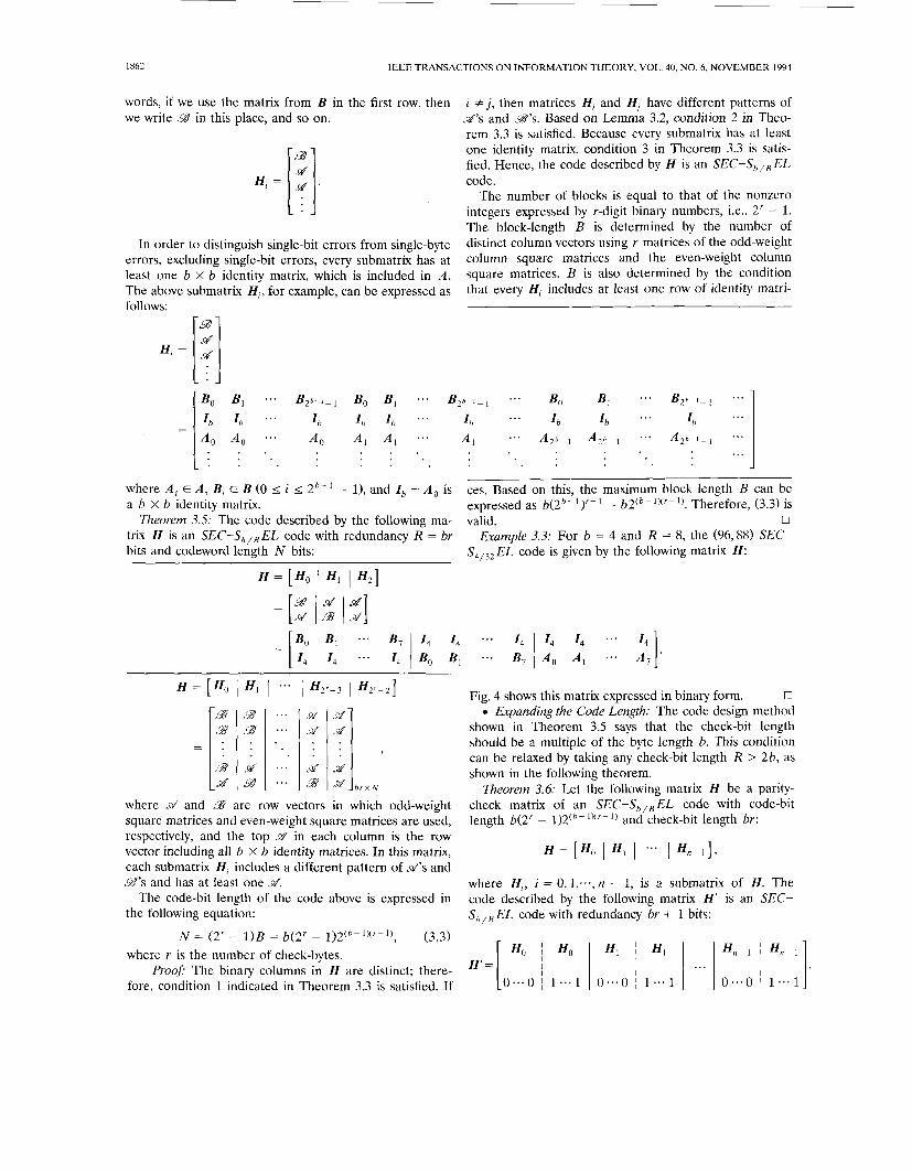
Theorem 3.5: The code described by the following ma- trix H is an sEC-s,,,EL code with redundancy R = br bits and codeword length N bits:
H = [Ho I Hl 1 H*]
Bo B , 1..
I , I , *..
H = [ H o 1 HI I ..* 1 ff2r-3 1 H 2 r - 2 ]
d d
- - . . 9 d * . * &fd
b r X N
where &f and 99 are row vectors in which odd-weight square matrices and even-weight square matrices are used, respectively, and the top szf in each column is the row vector including all b X b identity matrices. In this matrix, each submatrix Hi includes a different pattern of M's and 9 ' s and has at least one &?.
The code-bit length of the code above is expressed in the following equation:
(3.3) N = (2' - 1)B = b(2' - 1)2(b-1Xr-1) , where r is the number of check-bytes.
Proo$ The binary columns in H are distinct; there- fore, condition 1 indicated in Theorem 3.3 is satisfied. If
Fig. 4 shows this matrix expressed in binary form. 0 Expanding the Code Length: The code design method
shown in Theorem 3.5 says that the check-bit length should be a multiple of the byte length b. This condition can be relaxed by taking any check-bit length R > 2b, as shown in the following theorem.
Theorem 3.6: Let the following matrix H be a parity- check matrix of an SEC-S,,,EL code with code-bit length b(2' - 1)2(,- I X r - and check-bit length br:
H = [ H o I H , 1 . - * 1 Hn-l] ,
where H I , i = 0, 1;.., II - 1, is a submatrix of H. The code described by the following matrix H' is an SEC- Sb,,EL code with redundancy br + 1 bits:
FUJIWARA AND KITAKAMI: ERROR-LOCATING CODES FOR MEMORY SYSTEMS 1863
H =
0000 1111 0000 0000 1111 1111 0000 1111
0000 1111 1111 0000 0000 0000 1111 1111
0000 0000 1111 1111 0000 1111 0000 1111
0000 0000 0000 1111 1111 0000 1111 1111
1000 1000 1000 1000 1000 1000 1000 1000
0100 0100 0100 0100 0100 0100 0100 0100
0010 0010 0010 0010 0010 0010 0010 0010
0001 0001 0001 0001 0001 0001 0001 ooni
1000 1000 1000 1000 1000 1000 1000 1000
0100 0100 0100 0100 0100 0100 0100 0100
0010 0010 0010 0010 0010 0010 0010 0010
0001 0001 0001 0001 0001 0001 0001 0001
0000 1111 0000 0000 I 1 1 1 1111 0000 1111
0000 1111 1111 0000 0000 0000 1111 1111
0000 0000 1111 1111 0000 1111 0000 1111
0000 0000 0000 1111 1111 0000 1111 1111
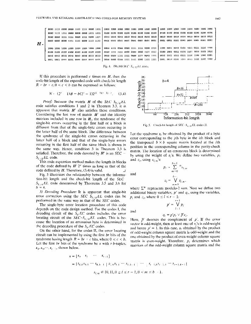
Fig. 4. (96,88) SEC-S,,,,EL code.
If this procedure is performed c times on H , then the code-bit length of the expanded code with check-bit length R = br + c,O I c < b can be expressed as follows:
N = (2' - l ) B = b(2' - 1)2(h-1Xr-l)+c. (3.4)
Pro#$ Because the matrix H of the SEC-S,,,EL code satisfies conditions 1 and 2 in Theorem 3.3, it is apparent that matrix H' also satisfies these conditions. Considering the last row of matrix H' and the identity matrices included in one row in H, , the syndrome of the single-bit errors occurring in the first half of a block is different from that of the single-byte errors occurring in the latter half of the same block. The difference between the syndrome of the single-bit errors occurring in the latter half of a block and that of the single-byte errors occurring in the first half of the same block is shown in the same way. Hence, condition 3 in Theorem 3.3 is satisfied. Therefore, the code denoted by H' is an SEC - S,,,EL code.
This code expansion method makes the length in blocks of the code defined by H' 2" times as long as that of the
0 Fig. 5 illustrates the relationship between the informa-
tion-bit length and the check-bit length of the SEC- S,,,EL code determined by Theorems 3.5 and 3.6 for b = 4.
3) Decoding Procedure: It is apparent that single-bit error correction using the sEc-s,,,EL codes can be performed in the same way as that of the SEC codes.
The single-byte error location procedure of this code depends on the code design method. For the codes I, the decoding circuit of the S,,,EC codes includes the error locating circuit of the SEC-S,,,EL codes. This is be- cause the location of an erroneous byte is determined in the decoding procedure of the S,!EC codes.
On the other hand, for the codes 11, the error locating circuit can be implemented by using the first br bits of the syndrome having length R = br + c bits, where 0 I c < b. Let the first br bits of the syndrome be s with r b-tuples, so, s1;.., s,- ,, shown below.
code defined by H . Therefore, (3.4) is valid.
28-
1000 1000 1000 1000 1000 1000 1000 1000
0100 0100 0100 0100 0100 0100 0100 0100
0010 0010 0010 0010 0010 0010 0010 0010
0001 0001 0001 0001 0001 0001 0001 0001
1000 0001 0010 0101 1011 0111 1110 1100
0100 1001 0011 0110 1101 1010 0101 1010
0010 0101 1011 0111 1110 1100 1000 0001
0001 0010 0101 1011 0111 1110 1100 1000
L 64 128 256 512 1024 2048
Information-bit length
Fig. 5. Check-bit length of SEC-S,,,EL codes I1
Let the syndrome sI be obtained by the product of a byte error corresponding to the j th byte in the ith block and the transposed b x b square matrix located at the Ith position in the corresponding column in the parity-check matrix. The location of an erroneous block is determined by using the weight of s,'s. We define two variables, p I and z l , using sI,m's:
h - I
PI = c %,m
v SI, 111 2
m=O and
b - 1
=I = m=O
where E' represents modulo-2 sum. Next we define two additional binary variables, p ' and qI , using the variables, p I and z I , where 0 I 1 I r - 1:
r - 1
P' = v PI
91 = PIP, v F Z I .
I = 1 and
Here, p' denotes the complement of p'. If the error vector is odd-weight, then at least one of si's is odd-weight and hence p' = 1. In this case, sI obtained by the product of odd-weight column square matrix is odd-weight and the one obtained by the product of even-weight column square matrix is even-weight. Therefore, p I determines which matrices of the odd-weight column square matrix and the
... ... = [ s O , O s O , l * * * SO,h-l I s l , O s I , l "' S l , h - l I I s r - I , O s r - l , I S r - l , h - l ]
s ~ , ~ ~ E (0,1),0 I I I r - 1,O I m I b - 1.
1864
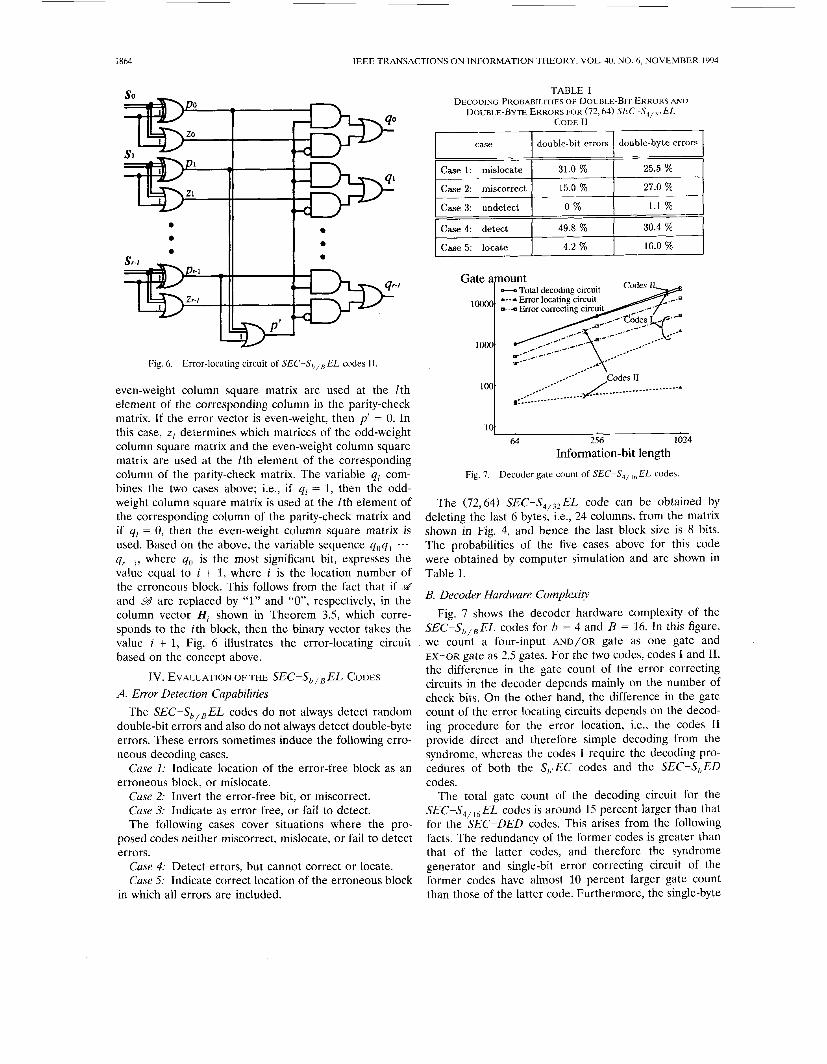
case double-bit errors
IEEE TRANSACTIONS ON INFORMATION THEORY, VOL. 40, NO. 6, NOVEMBER 1994
double-byte errors
Case 4: detect
Case 5: locate I : 49.8 % 30.4 %
4.2 % 16.0 %
1 I
Fig. 6. Error-locating circuit of SEC-S,,,EL codes 11.
even-weight column square matrix are used at the lth element of the corresponding column in the parity-check matrix. If the error vector is even-weight, then p’ = 0. In this case, z1 determines which matrices of the odd-weight column square matrix and the even-weight column square matrix are used at the lth element of the corresponding column of the parity-check matrix. The variable qr com- bines the two cases above; i.e., if qr = 1, then the odd- weight column square matrix is used at the fth element of the corresponding column of the parity-check matrix and if ql = 0, then the even-weight column square matrix is used. Based on the above, the variable sequence qoq, ... q r p l , where qo is the most significant bit, expresses the value equal to i + 1, where i is the location number of the erroneous block. This follows from the fact that if d and 99 are replaced by “1” and “0”, respectively, in the column vector H, shown in Theorem 3.5, which corre- sponds to the ith block, then the binary vector takes the value i + 1, Fig. 6 illustrates the error-locating circuit based on the concept above.
Iv. EVALUATION OF THE SEc-S,,,EL CODES
A. Error Detection Capabilities The SEC-S,,,EL codes do not always detect random
double-bit errors and also do not always detect double-byte errors. These errors sometimes induce the following erro- neous decoding cases.
Case I : Indicate location of the error-free block as an erroneous block, or mislocate.
Case 2: Invert the error-free bit, or miscorrect. Case 3: Indicate as error free, or fail to detect. The following cases cover situations where the pro-
posed codes neither miscorrect, mislocate, or fail to detect errors.
Case 4: Detect errors, but cannot correct or locate. Case 5: Indicate correct location of the erroneous block
in which all errors are included.
31.0 % 25.5 %
1.1 %
1000 **.---
..---
1 0 0 64 256 1024
Information-bit length
Fig. 7. Decoder gate count of SEC-S,,,,EL codes.
The (72,641 SEC-S,,-,,EL code can be obtained by deleting the last 6 bytes, i.e., 24 columns, from the matrix shown in Fig. 4, and hence the last block size is 8 bits. The probabilities of the five cases above for this code were obtained by computer simulation and are shown in Table I.
B. Decoder Hardware Complexity Fig. 7 shows the decoder hardware complexity of the
SEC-S,,, EL codes for b = 4 and B = 16. In this figure, we count a four-input AND/OR gate as one gate and EX-OR gate as 2.5 gates. For the two codes, codes I and 11, the difference in the gate count of the error correcting circuits in the decoder depends mainly on the number of check bits. On the other hand, the difference in the gate count of the error locating circuits depends on the decod- ing procedure for the error location, i.e., the codes I1 provide direct and therefore simple decoding from the syndrome, whereas the codes I require the decoding pro- cedures of both the S,<EC codes and the SEC-S,ED codes.
The total gate count of the decoding circuit for the SEC-S,,,, EL codes is around 15 percent larger than that for the SEC-DED codes. This arises from the following facts. The redundancy of the former codes is greater than that of the latter codes, and therefore the syndrome generator and single-bit error correcting circuit of the former codes have almost 10 percent larger gate count than those of the latter code. Furthermore, the single-byte
FUJIWARA AND KITAKAMI: ERROR-LOCATING CODES FOR MEMORY SYSTEMS 1865
error locating circuit is included in the decoder of the former codes.
C. Bounds
satisfy Theorem 4.1: Linear ( N , N - R)SEC-S,,,EL codes
R 2 2b. Proof For two bytes each belonging to different
blocks, there exist 2b column vectors in the parity-check matrix on GF(2). These vectors should be linearly inde- pendent due to the condition 2 in Theorem 3.3, and therefore the rank of the parity-check matrix should be 2b or more. 0
The codes I never satisfy the bounds above because b‘ is larger than b. On the other hand, some of the codes I1 satisfy the bounds.
Theorem 4.2: Linear (N, N - R ) sEC-s,,,EL codes satisfy
N I (4.1) B + 2‘ - b - 1 ‘
Proofi In the SEC-S,,,EL codes, in general, the syndromes caused by single-bit errors should be different from each other, and those caused by single-byte errors excluding single-bit errors should be different from the ones caused by single-bit errors. Therefore, the errors in one block have at least B + 2‘ - b - 1 different syn- dromes, and hence there are at least ( N / B ) ( B + 2’ - b - 1) different syndromes in the received word. Hence, the following inequality is satisfied:
B ( 2 R - 1)
N B
2R 2 - ( B + 2’ - b - 1) + 1.
From this, the inequality (4.1) follows. Fig. 8 shows these bounds for b = 4 and B = 60, com-
pared to the actual values for the proposed codes I and 11.
V. CONCLUSIONS This paper has proposed a new class of EL codes, the
S,,,EL codes and the SEC-S,,,EL codes, suitable for application to byte-organized semiconductor memory sys- tems.
5 2 4 I
b=4, B=60 P 8 U I . * . * . . * . * ‘
64 128 256 512 1024 2048 4096 8192 16384 32768 Information-bit length
Fig. 8. Bounds on check-bit length for SEC-S,,,o EL codes.
Codes combining further error control functions, such as error-correction and error detection, with error loca- tion capability, remain a topic for future study.
REFERENCES T. R. N. Rao and E. Fujiwara, Error-Control Coding for Conzputer Systems. M. Y. Hsiao, “A class of optimal minimum odd-weight-column SEC-DED codes,” IBM J . Res. Dec.., vol. 14, pp. 395-401, July 1970. C. L. Chen, “Fault-tolerant memory design in the IBM application system/400,” Dig. FTCS-21, pp. 393-400, June 1991. C. L. Chen and M. Y. Hsiao, “Error-correcting codes for semicon- ductor memory applications: A state of the art review,” IBM J . Res. Dec.., vol. 28, pp. 124-134, Mar. 1984. J. K. Wolf and B. Elspas, “Error-locating codes-A new concept in error control,” IEEE Trans. Inform. Theory, vol. IT-9, pp. 113-117, Apr. 1963. J . K. Wolf, “On codes derivable from the tensor product of check matrices,” IEEE Trans. Inform. Theory, vol. IT-11, pp. 281-284, Apr. 1965. J. K. Wolf, “On an extended class of error-locating codes,” Inform. Control., vol. 8, pp. 163-169, 1965. S.-H. Chang and L.-J. Weng, “Error locating codes,” IEEE Int. Coni,. Rec., Part 7, pp. 252-258, 1965. J. M. Goethals, “Cyclic error-locating codes,” Inform. Control, vol. 10, pp. 378-385, 1967. N. H. Vaidya and D. K. Pradhan, “A new class of bit- and byte error control codes,” IEEE Trans. Inform. Theory, vol. 38, pp. 1617-1623, Sept. 1992. S. J. Hong and A. M. Patel, “A general class of maximal codes for computer applications,” IEEE Trans. Comput., vol. C-21, pp. 1322-1331, Dec. 1972. D. C. Bossen, L. C. Chang, and C. L. Chen, “Measurement and generation of error correcting code for package failures,” IEEE Trans. Comput., vol. C-27, pp. 201-204, Mar. 1978.
Englewood Cliffs, NJ: Prentice-Hall, 1989.

![X10 Tester - · PDF fileX10_Tester.can Page 3 of 128. 151 BYTE hasToSendWriteColumnConfig = 0; 152 BYTE hasToSendWriteColumnDefault = 0; 153 154 BYTE StartLogicControl[6]; 155 BYTE](https://img.dokumen.tips/doc/110x75/5aa9f1037f8b9a9a188d968e/x10-tester-page-3-of-128-151-byte-hastosendwritecolumnconfig-0-152-byte-hastosendwritecolumndefault.jpg)