Embed Size (px)
Citation preview
on July 9, 2018http://rsif.royalsocietypublishing.org/Downloaded from
rsif.royalsocietypublishing.org
ResearchCite this article: Droogendijk H, de Boer MJ,
Sanders RGP, Krijnen GJM. 2014 A biomimetic
accelerometer inspired by the cricket’s clavate
hair. J. R. Soc. Interface 11: 20140438.
http://dx.doi.org/10.1098/rsif.2014.0438
Received: 26 April 2014
Accepted: 21 May 2014
Subject Areas:biomimetics, biomechanics, mathematical
physics
Keywords:accelerometer, cricket, MEMS, bio-inspired,
clavate hair
Author for correspondence:H. Droogendijk
e-mail: [email protected]
& 2014 The Author(s) Published by the Royal Society. All rights reserved.
A biomimetic accelerometer inspired bythe cricket’s clavate hair
H. Droogendijk, M. J. de Boer, R. G. P. Sanders and G. J. M. Krijnen
MESAþ Institute for Nanotechnology, University of Twente, Enschede, The Netherlands
Crickets use so-called clavate hairs to sense (gravitational) acceleration to
obtain information on their orientation. Inspired by this clavate hair system,
a one-axis biomimetic accelerometer has been developed and fabricated
using surface micromachining and SU-8 lithography. An analytical model is
presented for the design of the accelerometer, and guidelines are derived to
reduce responsivity due to flow-induced contributions to the accelerometer’s
output. Measurements show that this microelectromechanical systems
(MEMS) hair-based accelerometer has a resonance frequency of 320 Hz, a
detection threshold of 0.10 ms22 and a dynamic range of more than 35 dB.
The accelerometer exhibits a clear directional response to external accelerations
and a low responsivity to airflow. Further, the accelerometer’s physical limits
with respect to noise levels are addressed and the possibility for short-term
adaptation of the sensor to the environment is discussed.
1. IntroductionIn biology, mechanosensors, equipped with differing hair-like structures for
signal pick-up, are sensitive to a variety of physical quantities such as acceleration,
flow, rotational rate, balancing and IR-light [1,2]. As an example, crickets have
various types of hair-like receptors for measurement of several environmental
quantities. For sensing of low-frequency flows (typically less than 1 kHz) to
obtain information about the environment and avoid, for example, predator
attacks, crickets use filiform hairs, which are situated on the dorsal side of two
abdominal appendages called cerci and which are able to sense airflows with vel-
ocity amplitudes down to 30 mm s21 [3,4] and operate around the energy levels of
thermal noise [5]. Crickets gather also information about their environment by the
use of bristle hairs, which activate interneurons that respond to tactile stimuli of
the cercus and abdomen [6]. Further, crickets have club-shaped sensilla, called cla-
vate hairs, located on their cerci (figure 1), with hair lengths of 20–250 mm [8].
These clavate hairs turn out to be sensitive to (gravitational) acceleration, provid-
ing the cricket information on its orientation [7–10]. For example, a cricket uses its
clavate hairs to compensate head movement when it is rotated around its longi-
tudinal axis [11], for which such rotations can be measured with a resolution of
about 0.18 [9]. Additionally, Bischof [9] showed that these clavate hairs can
respond to harmonic accelerations with frequencies up to 300 Hz.
For measuring (gravitational) acceleration, numerous types of accelerometers
have been realized over the past years using microelectromechanical systems
(MEMS) technology, with applications in, for example, the automotive industry
and navigation [12]. Current state-of-the-art commercialized MEMS acceler-
ometers show formidable performance in range, resolution and noise floor. In
contrast to the cricket’s clavate system, MEMS accelerometers are usually not
hair-based systems and frequently contain feedback electronics. To explore
some of the intricacies of the clavate hair system and assess its potential for engin-
eering applications (e.g. automotive industry, robotics and motion tracking), we
aim to design, fabricate and characterize a biomimetic accelerometer. Biomimetic
hair-based structures have been exploited earlier with applications in both
actuation and sensing of physical quantities [13,14], but seldom for inertial
measurement. Previously, a hair-like accelerometer has been investigated by
Tang et al. [15], but its response to external accelerations was not demonstrated.
40
60
14
10
90806040
10
Figure 1. Artist’s reconstruction of the clavate hair-based sensory system (adapted from [7]).
rsif.royalsocietypublishing.orgJ.R.Soc.Interface
11:20140438
2
on July 9, 2018http://rsif.royalsocietypublishing.org/Downloaded from
In this paper, we present the design and fabrication of
a biomimetic accelerometer using MEMS technology and
report on its characterization with respect to externally applied
accelerations. We also assess, both theoretically and experimen-
tally, responsivity due to flow-induced contributions to the
accelerometer’s output and derive design guidelines on how
to reduce these effects. Further, we address the accelerometer’s
physical limits with respect to noise levels and discuss the possi-
bility for short-term adaptation of the sensor to the environment
by electrostatically tuning the sensor’s responsivity.
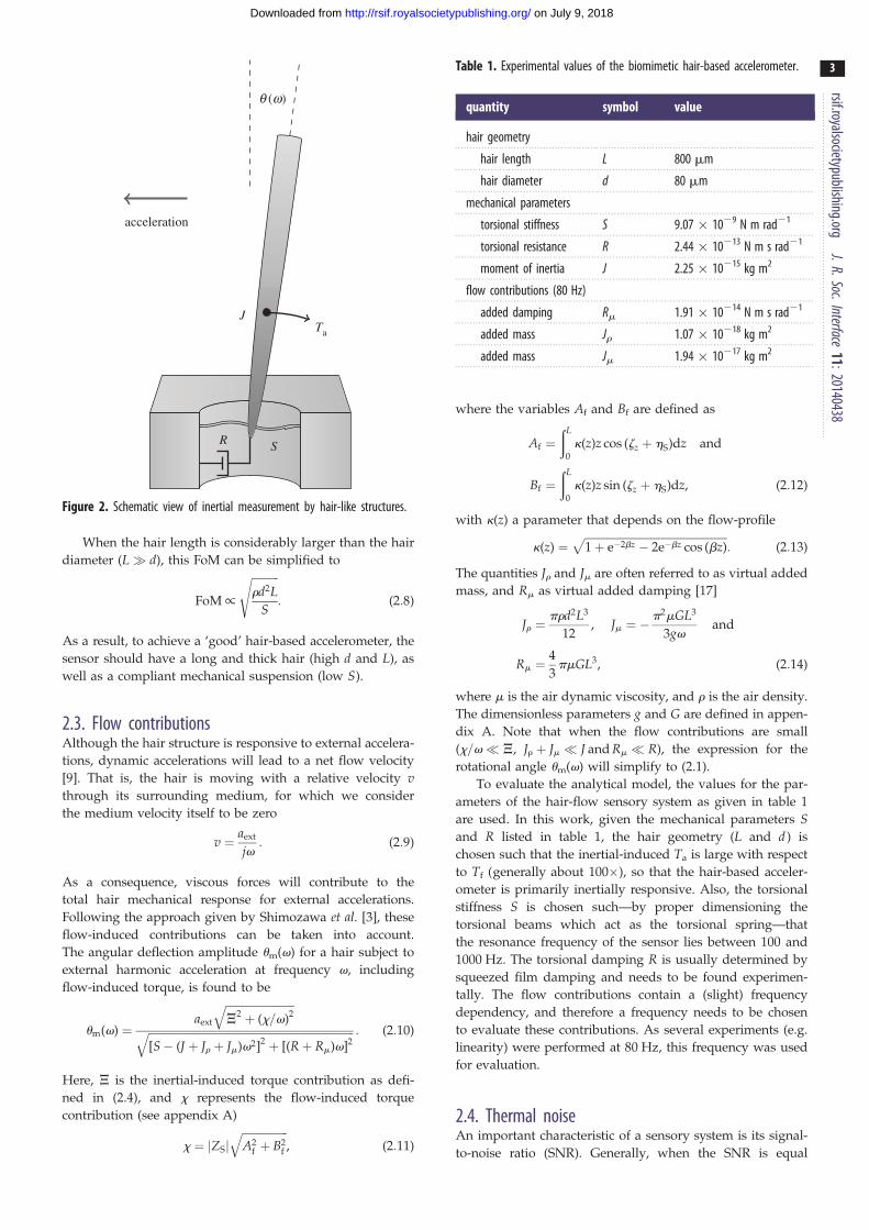
2. Theory and modelling2.1. Hair mechanicsMechanically, the hair-based accelerometer can be under-
stood as a so-called inverted pendulum which is subjected
to external accelerations (figure 2). It is described as a
second-order rotational-mechanical system with moment
of inertia J, a rotational stiffness S and a rotational damping
R, resulting in a description of the system’s response to
harmonic accelerations by
u(v) ¼ Ta
S� Jv2 þ jvR, (2:1)
where for a cylindrical hair, the moment of inertia can be
expressed as
J ¼ prd2
484L3 þ 3
4d2L
� �: (2:2)
In these expressions, u(v) is the rotational angle amplitude
of the hair and Ta is the amplitude of the torque acting on
the hair. Usually, in the models the hairs are treated as cylind-
rical structures [4], but here the hair is modelled as an
inverted conical shape to take the MEMS-hair-shape into
account. We will show that this eventually will only lead to
a geometry-dependent factor h such that J � hrd2L3.
From (2.2), the moment of inertia J depends strongly on the
hair diameter d and hair length L. The torque Ta is a
consequence of external accelerations, or the projections
thereof, in the direction perpendicular to the hair and perpen-
dicular to its rotation axis, denoted here by aext. Using
Newton’s second law, Ta is found by integrating the inertial
contributions by over the hair
Ta ¼ðL
0
aextrpd(z)
2
� �2
zdz ¼ J � aext, (2:3)
where J can be expressed as
J ¼ phr
8d2L2: (2:4)
In these expressions, r is the density of the hair and h a par-
ameter that depends on the precise geometry of the hair.
Further, we assume that the rotational angle amplitudes u are
small, so the torque Ta can be considered directly proportional
to the external acceleration aext.
2.2. DesignThe hair mechanical system behaves like a classical second-
order system and consequently exhibits the trade-off between
responsivity and bandwidth. The responsivity of the hair accel-
erometer for frequencies well below the system’s resonance
frequency (v� vr) is defined as
responsivity ¼ du(v)
daext
����v¼0
¼ ph
8
rd2L2
S: (2:5)
The bandwidth of the system is estimated from the system’s
resonance frequency
bandwidth ¼ vr ¼
ffiffiffiSJ
s: (2:6)
By taking the product of responsivity and bandwidth, a
figure of merit (FoM) can be defined for the biomime-
tic hair accelerometer, similar to the approach described by
Krijnen et al. [16]
FoM ¼ responsivity� bandwidth: (2:7)
SR
J
acceleration
Ta
q (w)
Figure 2. Schematic view of inertial measurement by hair-like structures.
Table 1. Experimental values of the biomimetic hair-based accelerometer.
quantity symbol value
hair geometry
hair length L 800 mm
hair diameter d 80 mm
mechanical parameters
torsional stiffness S 9.07 � 1029 N m rad21
torsional resistance R 2.44 � 10213 N m s rad21
moment of inertia J 2.25 � 10215 kg m2
flow contributions (80 Hz)
added damping Rm 1.91 � 10214 N m s rad21
added mass Jr 1.07 � 10218 kg m2
added mass Jm 1.94 � 10217 kg m2
rsif.royalsocietypublishing.orgJ.R.Soc.Interface
11:20140438
3
on July 9, 2018http://rsif.royalsocietypublishing.org/Downloaded from
When the hair length is considerably larger than the hair
diameter (L� d), this FoM can be simplified to
FoM/
ffiffiffiffiffiffiffiffiffiffird2L
S
s: (2:8)
As a result, to achieve a ‘good’ hair-based accelerometer, the
sensor should have a long and thick hair (high d and L), as
well as a compliant mechanical suspension (low S).
2.3. Flow contributionsAlthough the hair structure is responsive to external accelera-
tions, dynamic accelerations will lead to a net flow velocity
[9]. That is, the hair is moving with a relative velocity vthrough its surrounding medium, for which we consider
the medium velocity itself to be zero
v ¼ aext
jv: (2:9)
As a consequence, viscous forces will contribute to the
total hair mechanical response for external accelerations.
Following the approach given by Shimozawa et al. [3], these
flow-induced contributions can be taken into account.
The angular deflection amplitude um(v) for a hair subject to
external harmonic acceleration at frequency v, including
flow-induced torque, is found to be
um(v) ¼aext
ffiffiffiffiffiffiffiffiffiffiffiffiffiffiffiffiffiffiffiffiffiffiffiffiffiJ
2 þ (x=v)2q
ffiffiffiffiffiffiffiffiffiffiffiffiffiffiffiffiffiffiffiffiffiffiffiffiffiffiffiffiffiffiffiffiffiffiffiffiffiffiffiffiffiffiffiffiffiffiffiffiffiffiffiffiffiffiffiffiffiffiffiffiffiffiffiffiffiffiffiffiffiffiffiffiffiffiffi[S� (J þ Jr þ Jm)v2]2 þ [(Rþ Rm)v]2
q : (2:10)
Here, J is the inertial-induced torque contribution as defi-
ned in (2.4), and x represents the flow-induced torque
contribution (see appendix A)
x ¼ jZSjffiffiffiffiffiffiffiffiffiffiffiffiffiffiffiffiffiA2
f þ B2f
q, (2:11)
where the variables Af and Bf are defined as
Af ¼ðL
0
k(z)z cos (zz þ hS)dz and
Bf ¼ðL
0
k(z)z sin (zz þ hS)dz, (2:12)
with k(z) a parameter that depends on the flow-profile
k(z) ¼ffiffiffiffiffiffiffiffiffiffiffiffiffiffiffiffiffiffiffiffiffiffiffiffiffiffiffiffiffiffiffiffiffiffiffiffiffiffiffiffiffiffiffiffiffiffiffiffiffiffiffiffi1þ e�2bz � 2e�bz cos (bz)
p: (2:13)
The quantities Jr and Jm are often referred to as virtual added
mass, and Rm as virtual added damping [17]
Jr ¼prd2L3
12, Jm ¼ �
p2mGL3
3gvand
Rm ¼4
3pmGL3, (2:14)
where m is the air dynamic viscosity, and r is the air density.
The dimensionless parameters g and G are defined in appen-
dix A. Note that when the flow contributions are small
(x=v� J, Jr þ Jm � J and Rm � R), the expression for the
rotational angle um(v) will simplify to (2.1).
To evaluate the analytical model, the values for the par-
ameters of the hair-flow sensory system as given in table 1
are used. In this work, given the mechanical parameters Sand R listed in table 1, the hair geometry (L and d ) is
chosen such that the inertial-induced Ta is large with respect
to Tf (generally about 100�), so that the hair-based acceler-
ometer is primarily inertially responsive. Also, the torsional
stiffness S is chosen such—by proper dimensioning the
torsional beams which act as the torsional spring—that
the resonance frequency of the sensor lies between 100 and
1000 Hz. The torsional damping R is usually determined by
squeezed film damping and needs to be found experimen-
tally. The flow contributions contain a (slight) frequency
dependency, and therefore a frequency needs to be chosen
to evaluate these contributions. As several experiments (e.g.
linearity) were performed at 80 Hz, this frequency was used
for evaluation.
2.4. Thermal noiseAn important characteristic of a sensory system is its signal-
to-noise ratio (SNR). Generally, when the SNR is equal
SU-8
(a) (b)
Al
SixNy
SiO2
Si
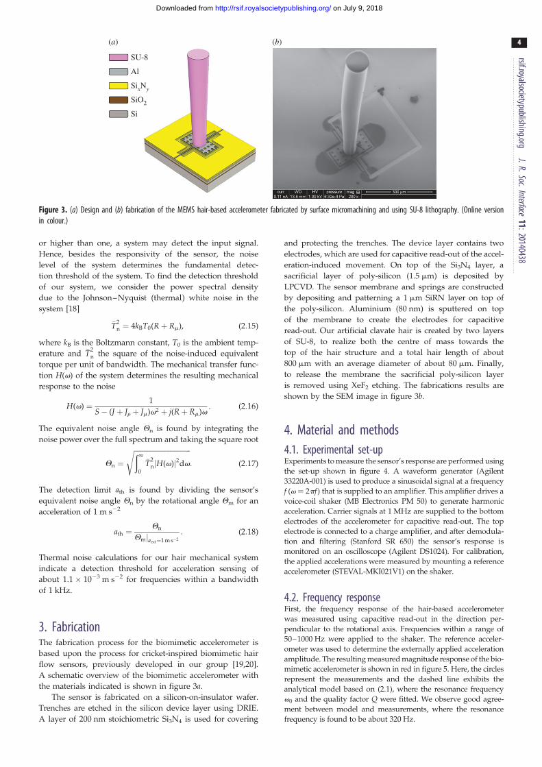
Figure 3. (a) Design and (b) fabrication of the MEMS hair-based accelerometer fabricated by surface micromachining and using SU-8 lithography. (Online versionin colour.)
rsif.royalsocietypublishing.orgJ.R.Soc.Interface
11:20140438
4
on July 9, 2018http://rsif.royalsocietypublishing.org/Downloaded from
or higher than one, a system may detect the input signal.
Hence, besides the responsivity of the sensor, the noise
level of the system determines the fundamental detec-
tion threshold of the system. To find the detection threshold
of our system, we consider the power spectral density
due to the Johnson–Nyquist (thermal) white noise in the
system [18]
�T2n ¼ 4kBT0(Rþ Rm), (2:15)
where kB is the Boltzmann constant, T0 is the ambient temp-
erature and �T2n the square of the noise-induced equivalent
torque per unit of bandwidth. The mechanical transfer func-
tion H(v) of the system determines the resulting mechanical
response to the noise
H(v) ¼ 1
S� (J þ Jr þ Jm)v2 þ j(Rþ Rm)v: (2:16)
The equivalent noise angle Qn is found by integrating the
noise power over the full spectrum and taking the square root
Qn ¼
ffiffiffiffiffiffiffiffiffiffiffiffiffiffiffiffiffiffiffiffiffiffiffiffiffiffiffiffiffiffiffiffiffið1
0
�T2njH(v)j2dv
s: (2:17)
The detection limit ath is found by dividing the sensor’s
equivalent noise angle Qn by the rotational angle Qm for an
acceleration of 1 m s22
ath ¼Qn
Qmjaext¼1 m s�2
: (2:18)
Thermal noise calculations for our hair mechanical system
indicate a detection threshold for acceleration sensing of
about 1.1 � 1023 m s22 for frequencies within a bandwidth
of 1 kHz.
3. FabricationThe fabrication process for the biomimetic accelerometer is
based upon the process for cricket-inspired biomimetic hair
flow sensors, previously developed in our group [19,20].
A schematic overview of the biomimetic accelerometer with
the materials indicated is shown in figure 3a.
The sensor is fabricated on a silicon-on-insulator wafer.
Trenches are etched in the silicon device layer using DRIE.
A layer of 200 nm stoichiometric Si3N4 is used for covering
and protecting the trenches. The device layer contains two
electrodes, which are used for capacitive read-out of the accel-
eration-induced movement. On top of the Si3N4 layer, a
sacrificial layer of poly-silicon (1.5 mm) is deposited by
LPCVD. The sensor membrane and springs are constructed
by depositing and patterning a 1 mm SiRN layer on top of
the poly-silicon. Aluminium (80 nm) is sputtered on top
of the membrane to create the electrodes for capacitive
read-out. Our artificial clavate hair is created by two layers
of SU-8, to realize both the centre of mass towards the
top of the hair structure and a total hair length of about
800 mm with an average diameter of about 80 mm. Finally,
to release the membrane the sacrificial poly-silicon layer
is removed using XeF2 etching. The fabrications results are
shown by the SEM image in figure 3b.
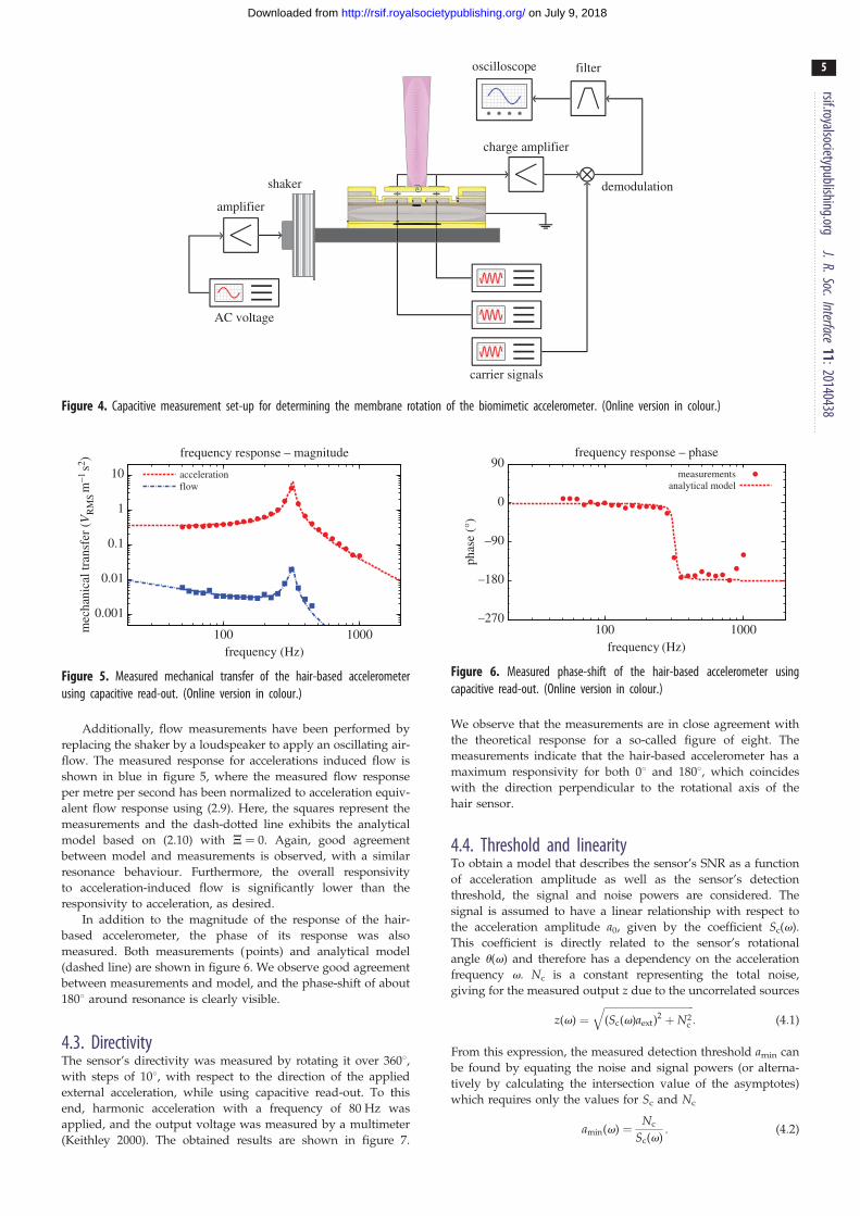
4. Material and methods4.1. Experimental set-upExperiments to measure the sensor’s response are performed using
the set-up shown in figure 4. A waveform generator (Agilent
33220A-001) is used to produce a sinusoidal signal at a frequency
f (v ¼ 2pf ) that is supplied to an amplifier. This amplifier drives a
voice-coil shaker (MB Electronics PM 50) to generate harmonic
acceleration. Carrier signals at 1 MHz are supplied to the bottom
electrodes of the accelerometer for capacitive read-out. The top
electrode is connected to a charge amplifier, and after demodula-
tion and filtering (Stanford SR 650) the sensor’s response is
monitored on an oscilloscope (Agilent DS1024). For calibration,
the applied accelerations were measured by mounting a reference
accelerometer (STEVAL-MKI021V1) on the shaker.
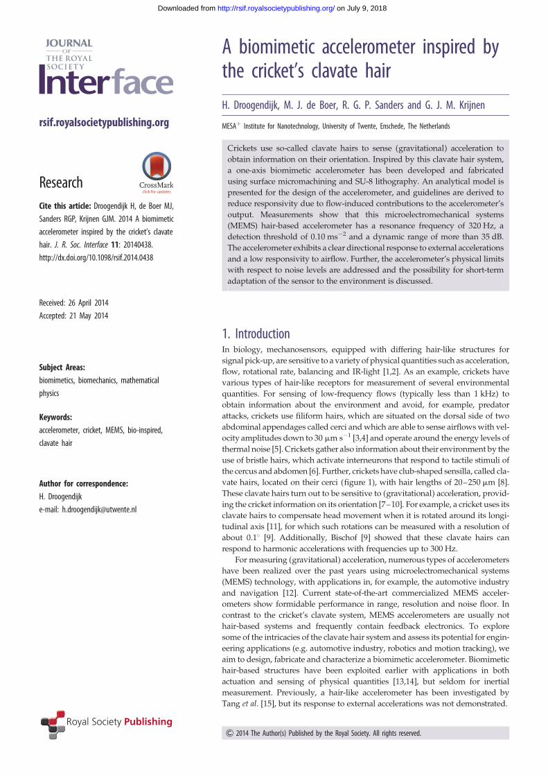
4.2. Frequency responseFirst, the frequency response of the hair-based accelerometer
was measured using capacitive read-out in the direction per-
pendicular to the rotational axis. Frequencies within a range of
50–1000 Hz were applied to the shaker. The reference acceler-
ometer was used to determine the externally applied acceleration
amplitude. The resulting measured magnitude response of the bio-
mimetic accelerometer is shown in red in figure 5. Here, the circles
represent the measurements and the dashed line exhibits the
analytical model based on (2.1), where the resonance frequency
v0 and the quality factor Q were fitted. We observe good agree-
ment between model and measurements, where the resonance
frequency is found to be about 320 Hz.
AC voltage
carrier signals
shaker
oscilloscope filter
demodulation
charge amplifier
amplifier
Figure 4. Capacitive measurement set-up for determining the membrane rotation of the biomimetic accelerometer. (Online version in colour.)
0.001
0.01
0.1
1
10
1000100mec
hani
cal t
rans
fer
(VR
MS
m–1
s2 )
frequency (Hz)
frequency response – magnitude
accelerationflow
Figure 5. Measured mechanical transfer of the hair-based accelerometerusing capacitive read-out. (Online version in colour.)
–270
–180
–90
0
90
1000100
phas
e (°
)
frequency (Hz)
frequency response – phase
measurementsanalytical model
Figure 6. Measured phase-shift of the hair-based accelerometer usingcapacitive read-out. (Online version in colour.)
rsif.royalsocietypublishing.orgJ.R.Soc.Interface
11:20140438
5
on July 9, 2018http://rsif.royalsocietypublishing.org/Downloaded from
Additionally, flow measurements have been performed by
replacing the shaker by a loudspeaker to apply an oscillating air-
flow. The measured response for accelerations induced flow is
shown in blue in figure 5, where the measured flow response
per metre per second has been normalized to acceleration equiv-
alent flow response using (2.9). Here, the squares represent the
measurements and the dash-dotted line exhibits the analytical
model based on (2.10) with J ¼ 0. Again, good agreement
between model and measurements is observed, with a similar
resonance behaviour. Furthermore, the overall responsivity
to acceleration-induced flow is significantly lower than the
responsivity to acceleration, as desired.
In addition to the magnitude of the response of the hair-
based accelerometer, the phase of its response was also
measured. Both measurements (points) and analytical model
(dashed line) are shown in figure 6. We observe good agreement
between measurements and model, and the phase-shift of about
1808 around resonance is clearly visible.
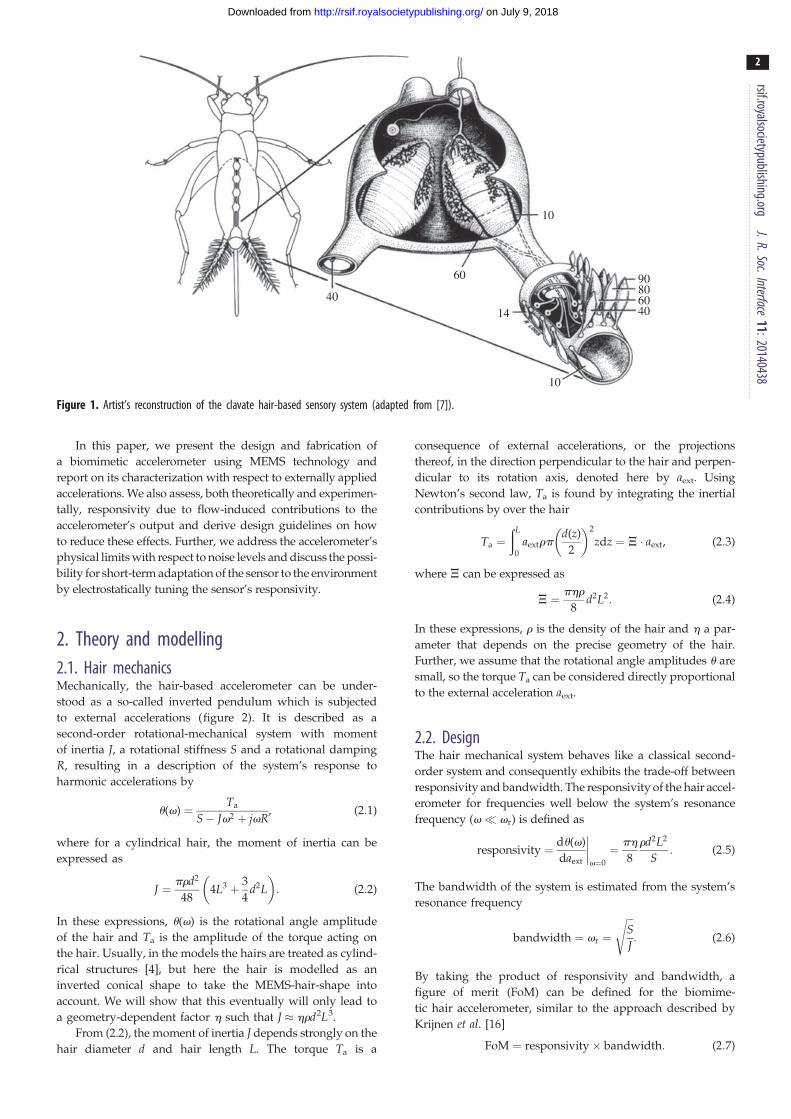
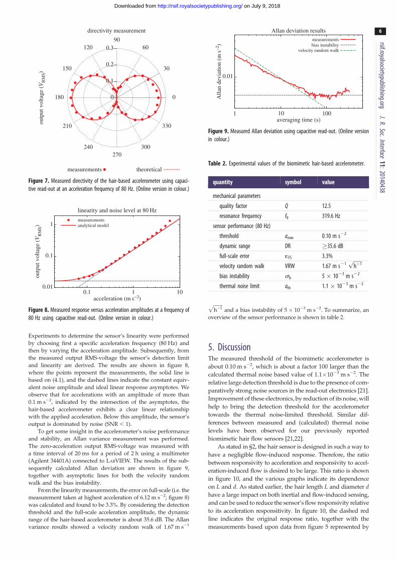
4.3. DirectivityThe sensor’s directivity was measured by rotating it over 3608,with steps of 108, with respect to the direction of the applied
external acceleration, while using capacitive read-out. To this
end, harmonic acceleration with a frequency of 80 Hz was
applied, and the output voltage was measured by a multimeter
(Keithley 2000). The obtained results are shown in figure 7.
We observe that the measurements are in close agreement with
the theoretical response for a so-called figure of eight. The
measurements indicate that the hair-based accelerometer has a
maximum responsivity for both 08 and 1808, which coincides
with the direction perpendicular to the rotational axis of the
hair sensor.
4.4. Threshold and linearityTo obtain a model that describes the sensor’s SNR as a function
of acceleration amplitude as well as the sensor’s detection
threshold, the signal and noise powers are considered. The
signal is assumed to have a linear relationship with respect to
the acceleration amplitude a0, given by the coefficient Sc(v).
This coefficient is directly related to the sensor’s rotational
angle u(v) and therefore has a dependency on the acceleration
frequency v. Nc is a constant representing the total noise,
giving for the measured output z due to the uncorrelated sources
z(v) ¼ffiffiffiffiffiffiffiffiffiffiffiffiffiffiffiffiffiffiffiffiffiffiffiffiffiffiffiffiffiffiffiffiffiffiffi(Sc(v)aext)
2 þN2c
q: (4:1)
From this expression, the measured detection threshold amin can
be found by equating the noise and signal powers (or alterna-
tively by calculating the intersection value of the asymptotes)
which requires only the values for Sc and Nc
amin(v) ¼ Nc
Sc(v): (4:2)
0
0.1
0.2
outp
ut v
olta
ge (
VR
MS)
0.3
directivity measurement
0
30
6090
120
150
180
210
240270
300
330
measurements theoretical
Figure 7. Measured directivity of the hair-based accelerometer using capaci-tive read-out at an acceleration frequency of 80 Hz. (Online version in colour.)
0.01
0.1
1
0.1 1 10
outp
ut v
olta
ge (
VR
MS)
acceleration (m s−2)
linearity and noise level at 80 Hz
measurementsanalytical model
Figure 8. Measured response versus acceleration amplitudes at a frequency of80 Hz using capacitive read-out. (Online version in colour.)
0.01
1
Alla
n de
viat
ion
(ms–2
)
averaging time (s)
Allan deviation results
measurementsbias instability
velocity random walk
10 100
Figure 9. Measured Allan deviation using capacitive read-out. (Online versionin colour.)
Table 2. Experimental values of the biomimetic hair-based accelerometer.
quantity symbol value
mechanical parameters
quality factor Q 12.5
resonance frequency f0 319.6 Hz
sensor performance (80 Hz)
threshold amin 0.10 m s22
dynamic range DR �35.6 dB
full-scale error 1FS 3.3%
velocity random walk VRW 1.67 m s21ffiffiffiffiffiffih�1p
bias instability sb 5 � 1023 m s22
thermal noise limit ath 1.1 � 1023 m s22
rsif.royalsocietypublishing.orgJ.R.Soc.Interface
11:20140438
6
on July 9, 2018http://rsif.royalsocietypublishing.org/Downloaded from
Experiments to determine the sensor’s linearity were performed
by choosing first a specific acceleration frequency (80 Hz) and
then by varying the acceleration amplitude. Subsequently, from
the measured output RMS-voltage the sensor’s detection limit
and linearity are derived. The results are shown in figure 8,
where the points represent the measurements, the solid line is
based on (4.1), and the dashed lines indicate the constant equiv-
alent noise amplitude and ideal linear response asymptotes. We
observe that for accelerations with an amplitude of more than
0.1 m s22, indicated by the intersection of the asymptotes, the
hair-based accelerometer exhibits a clear linear relationship
with the applied acceleration. Below this amplitude, the sensor’s
output is dominated by noise (SNR , 1).
To get some insight in the accelerometer’s noise performance
and stability, an Allan variance measurement was performed.
The zero-acceleration output RMS-voltage was measured with
a time interval of 20 ms for a period of 2 h using a multimeter
(Agilent 34401A) connected to LABVIEW. The results of the sub-
sequently calculated Allan deviation are shown in figure 9,
together with asymptotic lines for both the velocity random
walk and the bias instability.
From the linearity measurements, the error on full-scale (i.e. the
measurement taken at highest acceleration of 6.12 m s22; figure 8)
was calculated and found to be 3.3%. By considering the detection
threshold and the full-scale acceleration amplitude, the dynamic
range of the hair-based accelerometer is about 35.6 dB. The Allan
variance results showed a velocity random walk of 1.67 m s21
ffiffiffiffiffiffiffiffih�1
pand a bias instability of 5 � 1023 m s22. To summarize, an
overview of the sensor performance is shown in table 2.
5. DiscussionThe measured threshold of the biomimetic accelerometer is
about 0.10 m s22, which is about a factor 100 larger than the
calculated thermal noise based value of 1.1�1023 m s22. The
relative large detection threshold is due to the presence of com-
paratively strong noise sources in the read-out electronics [21].
Improvement of these electronics, by reduction of its noise, will
help to bring the detection threshold for the accelerometer
towards the thermal noise-limited threshold. Similar dif-
ferences between measured and (calculated) thermal noise
levels have been observed for our previously reported
biomimetic hair flow sensors [21,22].
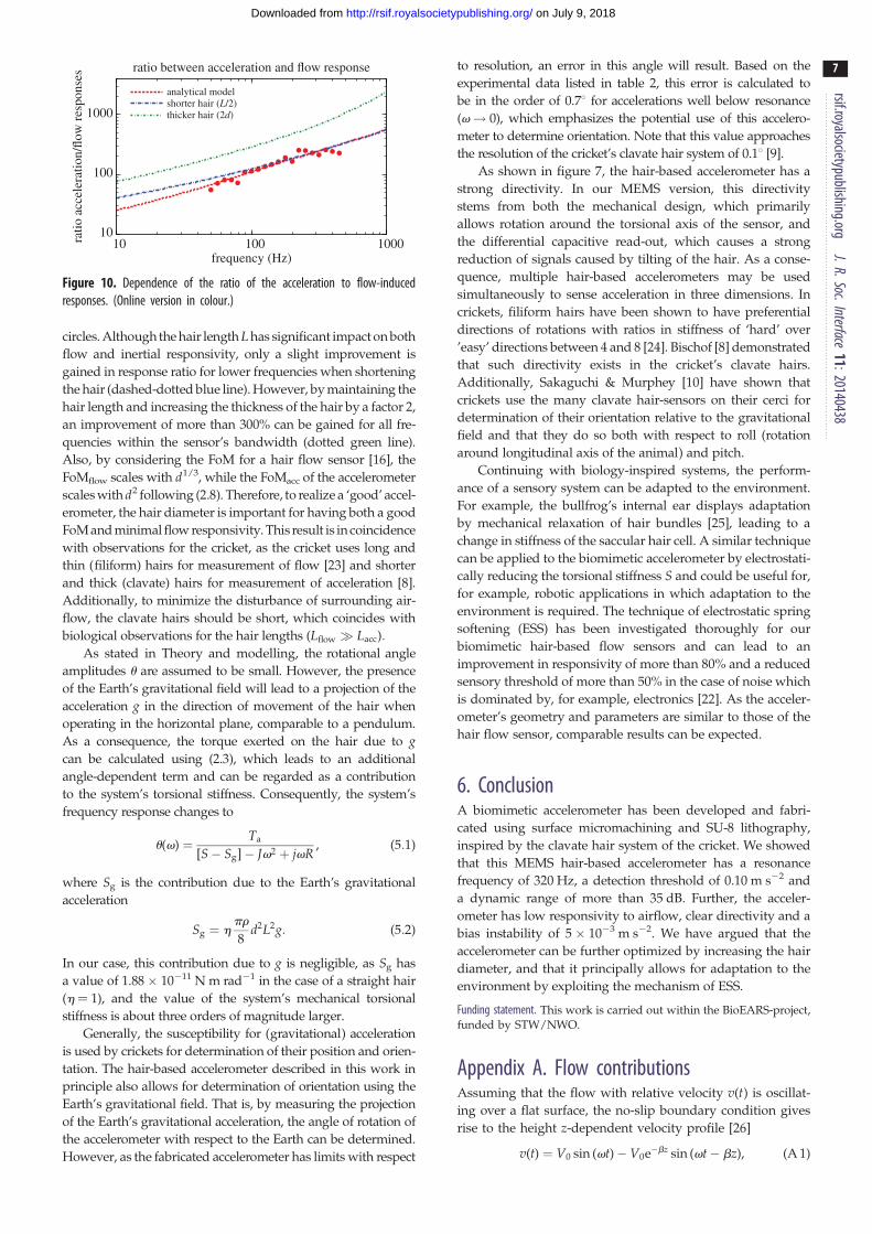
As stated in §2, the hair sensor is designed in such a way to
have a negligible flow-induced response. Therefore, the ratio
between responsivity to acceleration and responsivity to accel-
eration-induced flow is desired to be large. This ratio is shown
in figure 10, and the various graphs indicate its dependence
on L and d. As stated earlier, the hair length L and diameter dhave a large impact on both inertial and flow-induced sensing,
and can be used to reduce the sensor’s flow responsivity relative
to its acceleration responsitivity. In figure 10, the dashed red
line indicates the original response ratio, together with the
measurements based upon data from figure 5 represented by
10
100
1000
100010010ratio
acc
eler
atio
n/flo
w r
espo
nses
frequency (Hz)
ratio between acceleration and flow response
analytical modelshorter hair (L/2)thicker hair (2d)
Figure 10. Dependence of the ratio of the acceleration to flow-inducedresponses. (Online version in colour.)
rsif.royalsocietypublishing.orgJ.R.Soc.Interface
11:20140438
7
on July 9, 2018http://rsif.royalsocietypublishing.org/Downloaded from
circles. Although the hair length L has significant impact on both
flow and inertial responsivity, only a slight improvement is
gained in response ratio for lower frequencies when shortening
the hair (dashed-dotted blue line). However, by maintaining the
hair length and increasing the thickness of the hair by a factor 2,
an improvement of more than 300% can be gained for all fre-
quencies within the sensor’s bandwidth (dotted green line).
Also, by considering the FoM for a hair flow sensor [16], the
FoMflow scales with d1/3, while the FoMacc of the accelerometer
scales with d2 following (2.8). Therefore, to realize a ‘good’ accel-
erometer, the hair diameter is important for having both a good
FoM and minimal flow responsivity. This result is in coincidence
with observations for the cricket, as the cricket uses long and
thin (filiform) hairs for measurement of flow [23] and shorter
and thick (clavate) hairs for measurement of acceleration [8].
Additionally, to minimize the disturbance of surrounding air-
flow, the clavate hairs should be short, which coincides with
biological observations for the hair lengths (Lflow � Lacc):
As stated in Theory and modelling, the rotational angle
amplitudes u are assumed to be small. However, the presence
of the Earth’s gravitational field will lead to a projection of the
acceleration g in the direction of movement of the hair when
operating in the horizontal plane, comparable to a pendulum.
As a consequence, the torque exerted on the hair due to gcan be calculated using (2.3), which leads to an additional
angle-dependent term and can be regarded as a contribution
to the system’s torsional stiffness. Consequently, the system’s
frequency response changes to
u(v) ¼ Ta
[S� Sg]� Jv2 þ jvR, (5:1)
where Sg is the contribution due to the Earth’s gravitational
acceleration
Sg ¼ hpr
8d2L2g: (5:2)
In our case, this contribution due to g is negligible, as Sg has
a value of 1.88� 10211 N m rad21 in the case of a straight hair
(h ¼ 1), and the value of the system’s mechanical torsional
stiffness is about three orders of magnitude larger.
Generally, the susceptibility for (gravitational) acceleration
is used by crickets for determination of their position and orien-
tation. The hair-based accelerometer described in this work in
principle also allows for determination of orientation using the
Earth’s gravitational field. That is, by measuring the projection
of the Earth’s gravitational acceleration, the angle of rotation of
the accelerometer with respect to the Earth can be determined.
However, as the fabricated accelerometer has limits with respect
to resolution, an error in this angle will result. Based on the
experimental data listed in table 2, this error is calculated to
be in the order of 0.78 for accelerations well below resonance
(v! 0), which emphasizes the potential use of this accelero-
meter to determine orientation. Note that this value approaches
the resolution of the cricket’s clavate hair system of 0.18 [9].
As shown in figure 7, the hair-based accelerometer has a
strong directivity. In our MEMS version, this directivity
stems from both the mechanical design, which primarily
allows rotation around the torsional axis of the sensor, and
the differential capacitive read-out, which causes a strong
reduction of signals caused by tilting of the hair. As a conse-
quence, multiple hair-based accelerometers may be used
simultaneously to sense acceleration in three dimensions. In
crickets, filiform hairs have been shown to have preferential
directions of rotations with ratios in stiffness of ‘hard’ over
’easy’ directions between 4 and 8 [24]. Bischof [8] demonstrated
that such directivity exists in the cricket’s clavate hairs.
Additionally, Sakaguchi & Murphey [10] have shown that
crickets use the many clavate hair-sensors on their cerci for
determination of their orientation relative to the gravitational
field and that they do so both with respect to roll (rotation
around longitudinal axis of the animal) and pitch.
Continuing with biology-inspired systems, the perform-
ance of a sensory system can be adapted to the environment.
For example, the bullfrog’s internal ear displays adaptation
by mechanical relaxation of hair bundles [25], leading to a
change in stiffness of the saccular hair cell. A similar technique
can be applied to the biomimetic accelerometer by electrostati-
cally reducing the torsional stiffness S and could be useful for,
for example, robotic applications in which adaptation to the
environment is required. The technique of electrostatic spring
softening (ESS) has been investigated thoroughly for our
biomimetic hair-based flow sensors and can lead to an
improvement in responsivity of more than 80% and a reduced
sensory threshold of more than 50% in the case of noise which
is dominated by, for example, electronics [22]. As the acceler-
ometer’s geometry and parameters are similar to those of the
hair flow sensor, comparable results can be expected.
6. ConclusionA biomimetic accelerometer has been developed and fabri-
cated using surface micromachining and SU-8 lithography,
inspired by the clavate hair system of the cricket. We showed
that this MEMS hair-based accelerometer has a resonance
frequency of 320 Hz, a detection threshold of 0.10 m s22 and
a dynamic range of more than 35 dB. Further, the acceler-
ometer has low responsivity to airflow, clear directivity and a
bias instability of 5 � 1023 m s22. We have argued that the
accelerometer can be further optimized by increasing the hair
diameter, and that it principally allows for adaptation to the
environment by exploiting the mechanism of ESS.
Funding statement. This work is carried out within the BioEARS-project,funded by STW/NWO.
Appendix A. Flow contributionsAssuming that the flow with relative velocity v(t) is oscillat-
ing over a flat surface, the no-slip boundary condition gives
rise to the height z-dependent velocity profile [26]
v(t) ¼ V0 sin (vt)� V0e�bz sin (vt� bz), (A 1)
rsif.royalsocietypublishing.orgJ.R.Soc.Interface
11:20140438
8
on July 9, 2018http://rsif.royalsocietypublishing.org/Downloaded from
where b is proportional to the reciprocal of the boundary layer
thickness, with n the kinematic viscosity (b ¼ffiffiffiffiffiffiffiffiffiffiffiffiffiffiv=(2n)
p):Using
trigonometric identities, expression (A 1) is written as a
sinusoidal function with an amplitude Vz and phase-shift zz
vz(t) ¼ Vz sin (vtþ zz), (A 2)
where
Vz ¼ V0
ffiffiffiffiffiffiffiffiffiffiffiffiffiffiffiffiffiffiffiffiffiffiffiffiffiffiffiffiffiffiffiffiffiffiffiffiffiffiffiffiffiffiffiffiffiffiffiffiffiffiffiffi1þ e�2bz � 2e�bz cos (bz)
p(A 3)
and
zz ¼ arctane�bz sin (bz)
1� e�bz cos (bz)
� �: (A 4)
With the velocity profile given, the viscous forces exerted on
the hair are described in [27], under the assumption of small
angular displacements and low Reynolds and Strouhal num-
bers [4]. Following the analysis of Shimozawa et al. [3], the
torque Tf, due to the relative air-movement, acting upon the
hair can be expressed as
Tf ¼ffiffiffiffiffiffiffiffiffiffiffiffiffiffiffiffiffiA2 þ B2
p, (A 5)
where A and B are torque contributions given by
A ¼ðL
0
jZSjVzz cos (zz þ hS)dz and
B ¼ðL
0
jZSjVzz sin (zz þ hS)dz: (A 6)
In both A and B, the parameter Zs expresses the relation between
the oscillating airflow V and the force per unit length F
ZS ¼FV¼ ZSR þ jZSX, (A 7)
where
ZSR ¼ 4pmG and ZSX ¼prd2
4v� p2mG
g: (A 8)
In these expressions, G and g are dimensionless parameters
G ¼ �g
g2 þ (p=4)2, g ¼ gþ ln (s) and s ¼ d
4
ffiffiffiffiv
n
r: (A 9)
References
1. Liu C. 2007 Micromachined biomimetic artificialhaircell sensors. Bioinspir. Biomim. 2, 162 – 169.(doi:10.1088/1748-3182/2/4/S05)
2. Schmitz H, Soltner H, Bousack H. 2012 Biomimeticinfrared sensors based on photo-mechanic infraredreceptors in pyrophilous (‘fire-loving’) insects. IEEE Sens.J. 12, 281– 288. (doi:10.1109/JSEN.2010.2076324)
3. Shimozawa T, Kumagai T, Baba Y. 1998 Structuralscaling and functional design of the cercal wind-receptor hairs of cricket. J. Comp. Physiol. A 183,171 – 186. (doi:10.1007/s003590050245)
4. Humphrey J, Devarakonda R, Iglesias I, Barth F.1993 Dynamics of arthropod filiformhairs. I. Mathematical modeling of the hair and airmotions. Phil. Trans. R. Soc. Lond. B 340, 423 – 444.(doi:10.1098/rstb.1993.0083)
5. Shimozawa T, Murakami J, Kumagai T. 2003 Cricketwind receptors: thermal noise for the highestsensitivity known. In Sensors and sensing in biologyand engineering, ch. 10, pp. 145 – 159. New York,NY: Springer.
6. Murphey RK. 1985 A second cricket cercal sensorysystem: bristle hairs and the interneurons theyactivate. J. Comp. Physiol. A 156, 357 – 367. (doi:10.1007/BF00610728)
7. Murphey RK. 1981 The structure and developmentof a somatotopic map in crickets: the cercal afferentprojection. Dev. Biol. 88, 236 – 246. (doi:10.1016/0012-1606(81)90167-6)
8. Bischof H-J. 1974 Verteilung und bewegungsweiseder keulenformigen sensillen von gryllusbimaculatus. Biol. Zbl. 93, 449 – 457.
9. Bischof H-J. 1975 Die keulenformigen sensillenauf den cerci der grille gryllus bimaculatus alsschwererezeptoren. J. Comp. Physiol. A 98,277 – 288. (doi:10.1007/BF00656974)
10. Sakaguchi DS, Murphey RK. 1983 The equilibriumdetecting system of the cricket: physiology
and morphology of an identified interneuron.J. Comp. Physiol. A 150, 141 – 152. (doi:10.1007/BF00606364)
11. Horn E, Bischof H-J. 1983 Gravity reception incrickets: the influence of cercal and antennalafferences on the head position. J. Comp. Physiol. A150, 93 – 98. (doi:10.1007/BF00605292)
12. Yazdi N, Ayazi F, Najafi K. 1998 Micromachinedinertial sensors. Proc. IEEE 86, 1640 – 1659. (doi:10.1109/5.704269)
13. Zhou Z-G, Liu Z-W. 2008 Biomimetic cilia based onMEMS technology. J. Bionic Eng. 5, 358 – 365.(doi:10.1016/S1672-6529(08)60181-X)
14. Ginsberg M, Schiano J, Kramer M, Alleyne M. 2013A case study in bio-inspired engineering design:defense applications of exoskeletal sensors. Def.Secur. Anal. 29, 156 – 169. (doi:10.1080/14751798.2013.787798)
15. Tang Y, Peterson RL, Najafi K. Technology forfabricating dense 3-D microstructure arrays forbiomimetic hair-like sensors. In Proc. MEMS 2013,Taipei, Taiwan, 20 – 24 January 2013, pp. 355 – 358.Piscataway, NJ: IEEE.
16. Krijnen G, Floris A, Dijkstra M, Lammerink T,Wiegerink R. 2007 Biomimetic micromechanicaladaptive flow-sensor arrays. Proc. SPIE 6592, 65920F.
17. Humphrey JAC, Barth FG. 2008 Medium flow-sensing hairs: biomechanics and models. InAdvances in Insect Physiology. Insect Mechanics andControl. (eds J Casas, SJ Simpson), pp. 1 – 80.Oxford, UK: Elsevier.
18. Gabrielson TB. 1993 Mechanical thermal noise inmicromachined acoustic and vibration sensors. IEEETrans. Electron Devices 40, 903 – 909. (doi:10.1109/16.210197)
19. Bruinink CM, Jaganatharaja RK, de Boer MJ,Berenschot JW, Kolster ML, Lammerink TSJ,Wiegerink RJ, Krijnen GJM. 2009 Advancements in
technology and design of biomimetic flow-sensorarrays. In Proc. MEMS 2009 Conf., Sorrento, Italy,pp. 152 – 155. Piscataway, NJ: IEEE.
20. Dagamseh A, Lammerink T, Sanders R, Wiegerink R,Krijnen G. Towards high-resolution flow cameras madeof artificial hair flow-sensors for flow pattern recognition.In Proc. MEMS 2011, Cancun, Mexico, 23 – 27 January2011, pp. 648 – 651. Piscataway, NJ: IEEE.
21. Dagamseh AMK, Bruinink CM, Wiegerink RJ,Lammerink TSJ, Droogendijk H, Krijnen GJM. 2013Interfacing of differential-capacitive biomimetic hairflow-sensors for optimal sensitivity. J. Micromech.Microeng. 23, 035010. (doi:10.1088/0960-1317/23/3/035010)
22. Droogendijk H, Bruinink CM, Sanders RGP,Dagamseh AMK, Wiegerink RJ, Krijnen GJM. 2012Improving the performance of biomimetic hair-flowsensors by electrostatic spring softening.J. Micromech. Microeng. 22, 065026. (doi:10.1088/0960-1317/22/6/065026)
23. Miller JP, Krueger S, Heys JJ, Gedeon T. 2011Quantitative characterization of the filiformmechanosensory hair array on the cricket cercus. PLoSONE, 6, e27873. (doi:10.1371/journal.pone.0027873)
24. Kanou M, Osawa T, Shimozawa T. 1989 Mechanicalpolarization in the air-current sensory hair of acricket. Experientia 45, 1082 – 1083. (doi:10.1007/BF01950163)
25. Howard J, Hudspeth AJ. 1987 Mechanical relaxationof the hair bundle mediates adaptation inmechanoelectrical transduction by the bullfrog’ssaccular hair cell. Proc. Natl Acad. Sci. USA 84,3064 – 3068. (doi:10.1073/pnas.84.9.3064)
26. Panton RL. 1996 Incompressible flow. New York, NY:Wiley.
27. Stokes GG. 1851 On the effect of the interal frictionof fluids n the motion of pendulums. Trans. Camb.Phil. Soc. 9, 8ff.