Embed Size (px)
Citation preview
90/93 SERIES Full Port Ball Valve
150# / 300# ANSI Flanged
Installation & Maintenance Manual
1 December 7, 2011www.a-tcontrols.com \\Atfs1\Engineering\documents\products\IOM\IOM7003
Brief Introduction Split body (2-piece) valve allows easy replacement of gasket, seal, and seats without special tools. Series 90 ball valves use “floating ball” design. Induced by the line pressure the ball is free to move horizontally inside the valve body. The valve is capable of tight shutoff with flow in either direction or dead-end, regardless of the position of the valve in the line. The downstream seat, opposite the pressurized side of a closed valve, carries the load exerted by the line pressure on the ball, while the upstream seat is subject to little load or wear. For this reason, it is sometimes possible to increase seat life by turning the valve end-for-end in the pipeline. 1. USE: 1.1 Life of valve can be maximized if the valve is used within the rated range, in accordance with pressure, temperature,
and corrosion data. 2. MANUAL OPERATION: 2.1 To open or close the valve, turn the handle ¼ turn (90 degrees).
A. Valve in Open Position – the handle is in parallel (in-line) with the valve or pipeline. B. Valve in Closed Position – the handle is perpendicular (crossed) with the valve or pipeline.
3. AUTOMATED OPERATION: 3.1 Valves with actuators should be checked for valve stem alignment. Angular or linear misalignment will result in high
operational torque and unnecessary wear on the stem seal. 4. GENERAL INFORMATION FOR ON-SITE INSTALLATION: 4.1 The valve may be fitted in any position on the pipeline. 4.2 To prevent damage to the seats and ball surface, the pipeline must be flushed, free of dirt, burrs, and welding
residues before installing the valve. 5. DISASSEMBLING & CLEANING THE VALVE: 5.1 If the valve has been used in hazardous media, it must be decontaminated before disassembly. 5.2 As shipped from the factory, valves contain silicon-free lubricant. If lubricant is unacceptable for your particular
application, you may disassemble the valve and wash the parts in solvent. 6. REPLACING THE THRUST WASHER AND PACKING 6.1 Before replacing the thrust washer and the packing, the pipeline must be de-pressurized.
Note: Stem seal leakage may be corrected without replacing the seal and/or packing. Tighten the packing nut to flatten the belleville washers. If leakage continues or valve’s operating torque becomes excessive, the seals are worn and must be replaced.
A. Remove flange bolts and nuts and lift the valve from the line. Care should be taken to avoid scratching or damaging serrated gasket. The valves are heavy, and they should be adequately supported before removing it from the line.
B. Loosen the stem nut and remove handle and stop plate. Next, remove lock saddle, packing nuts, belleville washers and gland.
C. Remove body bolt nuts, using proper wrench. Lift off body end. One seat should come out with the body end. D. Remove body seal. E. To take out the ball, rotate stem so ball is in fully closed position. Lift ball from the body, using a strap and lift
device, if necessary. Extreme caution should be taken to avoid damage to the ball. F. Take out the other seat. G. Stem must be removed from inside the body. A tap to the top of the stem should loosen it. The thrust washer
should come out with the stem. Then, remove the stem packing.
90/93 SERIES Full Port Ball Valve
150# / 300# ANSI Flanged
Installation & Maintenance Manual
2 December 7, 2011www.a-tcontrols.com \\Atfs1\Engineering\documents\products\IOM\IOM7003
7. VISUAL INSPECTION: 7.1 Clean and inspect metal parts. It is not necessary to replace neither ball nor stem unless the surface has signs of
abrasion or corrosion. We strongly recommend replacement of all soft parts whenever the valve is disassembled for reconditioning. We provide replacement kits that contain all the replaceable parts. Note: The valve may be assembled and operated dry without any lubricant. However, a light lubrication will aid in
assembly and reduce initial operating torque. Lubricant used must be acceptable with the intended line fluid.
8. ASSEMBLY Install one seat in the body cavity with the spherical curvature facing the ball.
8.1 Install the thrust washer on stem and slide the stem up through the body. Install packing, gland, belleville washers, locking saddle. Screw the packing nut into the stem. Lock the saddle in place.
8.3 Install stop plate, handle and washer. Screw the stem nut into the stem until the handle is secure. 8.4 Turn handle to the closed position. Line up the ball slot with the stem end and slide the ball into position. Turn the
handle to the open position to hold the ball in place. 8.5 Install the remaining seat into body side. 8.6 Put body seal gasket into body and line up end flange. Because the body flange bolt pattern is different from the line
flange bolt pattern, it is possible to assemble the valve such that the line flanges bolt pattern don’t line up. Be certain to align end flanges bolt holes to straddle valve center lines. Be careful not to damage body seal when putting cap end into body.
8.8 Install cap end nuts and tighten in the “star” pattern to the proper torque. Extreme care must be exercised during adjustment of cap end nuts to make sure that complete engagement of the studs with body flange is maintained. There should be at least one stud thread exposed on each side.
8.9 Cycle the valve slowly, with a gentle back and forth motion, to build gradually to the full quarter turn. By cycling slowly, the seat lips will assume a permanent seal shape against the ball. A fast turning motion, at this point, may cut the seats before they have a chance to form the proper seal.
8.10 Test valve, if possible, prior to placing valve back into line position. If not properly secured, the valve can separate from the pressure source, resulting in possible injury. Always join the valve to companion flanges of same pressure rating as valve and secure with a full set of flange bolts.
TEST AS FOLLOWS: A. Secure valve to a test fixture by means of a mating flange with full bolting and a suitable gasket. Orient valve so
seat to be tested is facing up. B. Introduce 50 to 100 psig air. Partially cycle the valve, under pressure, then slowly close to make sure the cavity is
pressurized (use hearing protection). Pour water into the upper port to cover the ball and visually check for bubbles. If bubbles appear, pour the water out, cycle the valve several times and recheck. To check for leakage in the other port, reverse the valve and introduce air pressure to the port just checked.
C. Check stem seal at this time by coating the stem top area with a water/soap solution. If leakage occurs, tighten stem seal just until leakage stops.
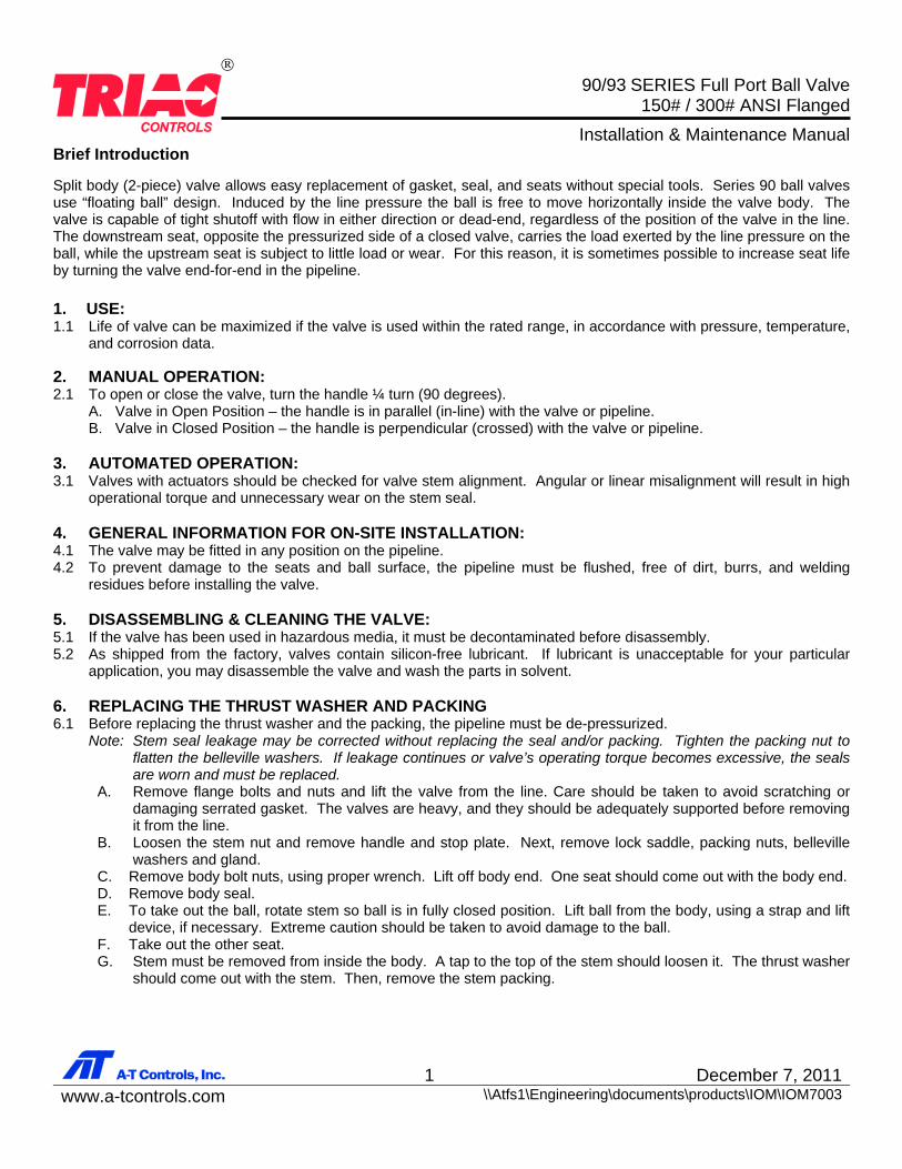
Valve Size Break Away Torque (In-lbs.) Torque of Body Bolts (In-lbs.) Torque of Stem Nut (In-lbs.)
½” 92 95 ~ 130 78 ¾” 127 122 ~ 156 78 1” 150 365 ~ 399 122
1-1/2” 311 365 ~ 399 191 2” 396 365 ~ 399 191
2-1/2” 657 365 ~ 399 191 3” 980 477 ~ 521 278 4” 1700 477 ~ 521 278 6” 4800 1042 (± 20%) 564 (± 20%) 8” 10300 1042 (± 20%) 564 (± 20%) 10” 18000 1216 (± 20%) 564 (± 20%) 12” CF 1216 (± 20%) 564 (± 20%)
90/93 SERIES Full Port Ball Valve
150# / 300# ANSI Flanged
Installation & Maintenance Manual
3 December 7, 2011www.a-tcontrols.com \\Atfs1\Engineering\documents\products\IOM\IOM7003
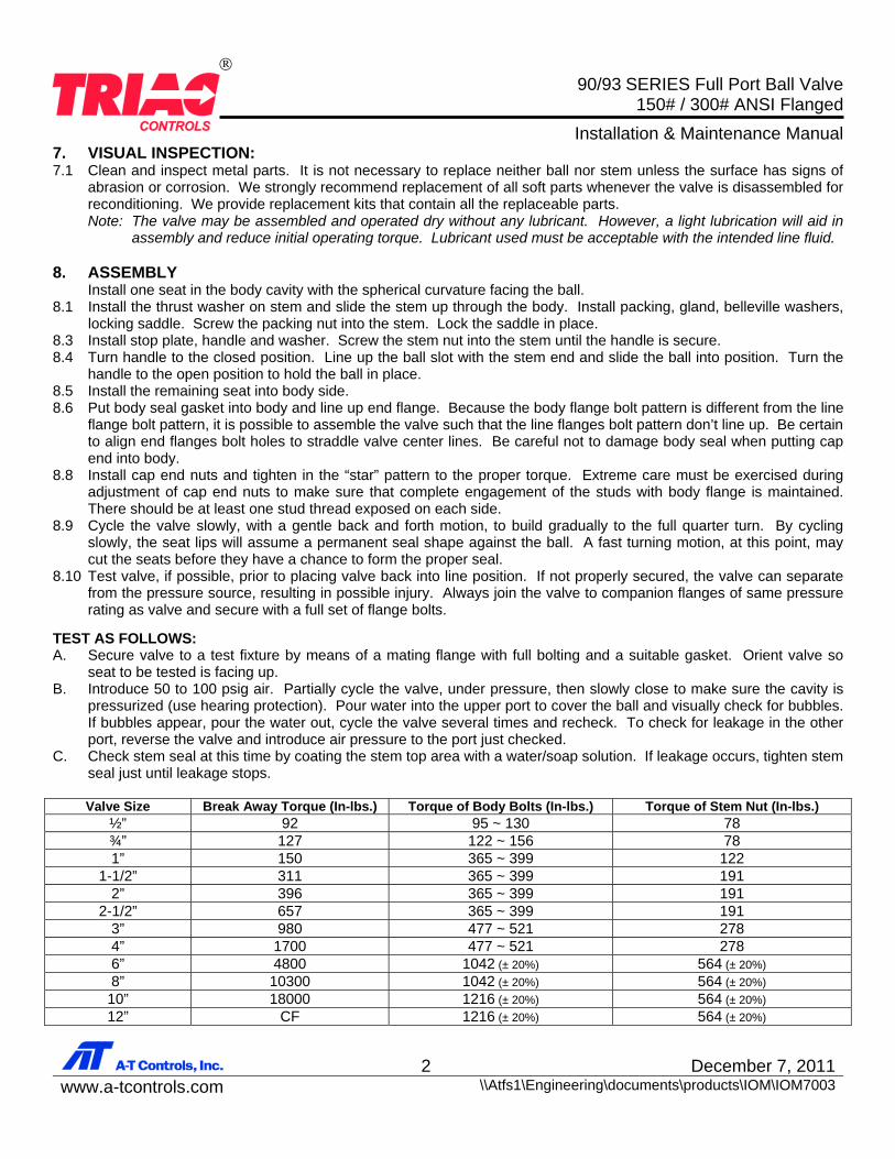
90 SERIES ½” – 4”
90/93 SERIES Full Port Ball Valve
150# / 300# ANSI Flanged
Installation & Maintenance Manual
4 December 7, 2011www.a-tcontrols.com \\Atfs1\Engineering\documents\products\IOM\IOM7003
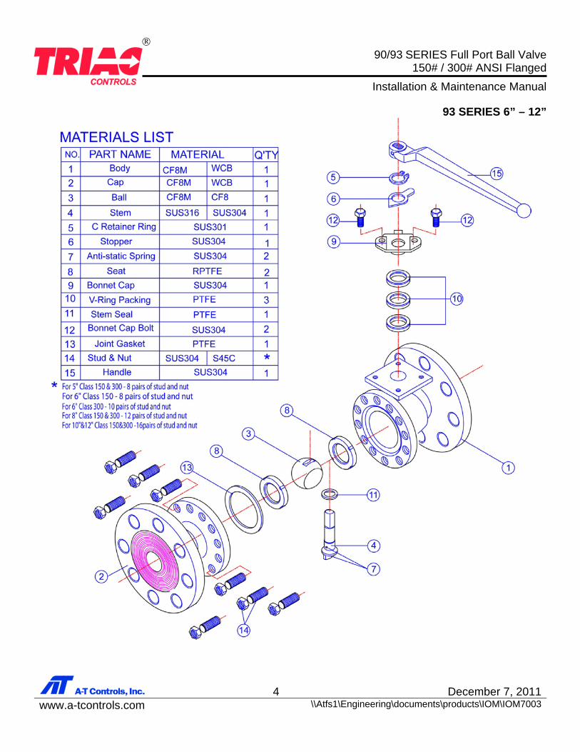
93 SERIES 6” – 12”
90/93 SERIES Full Port Ball Valve
150# / 300# ANSI Flanged
Installation & Maintenance Manual
5 December 7, 2011www.a-tcontrols.com \\Atfs1\Engineering\documents\products\IOM\IOM7003
A-T Controls product, when properly selected, is designed to perform its intended function safely during its useful life. However, the purchaser or user of A-T Controls products should be aware that A-T Controls products might be used in numerous applications under a wide variety of industrial service conditions. Although A-T Controls can provide general guidelines, it cannot provide specific data and warnings for all possible applications. The purchaser / user must therefore assume the ultimate responsibility for the proper sizing and selection, installation, operation, and maintenance of A-T Controls products. The user should read and understand the installation operation maintenance (IOM) instructions included with the product, and train its employees and contractors in the safe use of A-T Controls products in connection with the specific application. While the information and specifications contained in this literature are believed to be accurate, they are supplied for informative purposes only. Because A-T Controls is continually improving and upgrading its product design, the specifications, dimensions and information contained in this literature are subject to change without notice. Should any question arise concerning these specifications, the purchaser/user should contact A-T Controls. For product specifications go to http://download.a-tcontrols.com/ A-T Controls, Inc. • 9955 International Boulevard, Cincinnati, OH 45246 • Phone: (513) 530-5175 • Fax: (513) 247-5462 • www.a-tcontrols.com