Embed Size (px)
Citation preview

901P Loadlock Vacuum pressure transducer
RS232 / RS485 / Display
Operation and Installation Manual
P/N: 100017121 901P Loadlock Transducer Operation and Installation Manual Revision: J, March 2016

Extent of the Warranty MKS Instruments, Inc., HPS™ Products Inc. and MKS Denmark ApS. warrants the 901P LoadlockVacuum Transducer and its accessories to be free from defects in materials and workmanship for one (1) year from the date of shipment by HPS™ or authorized representative to the original purchaser (PURCHASER). Any product or parts of the product repaired or replaced by HPS™ under this warranty are warranted only for the remaining unexpired part of its one (1) year original warranty period. After expiration of the applicable warranty period, the PURCHASER shall be charged HPS™’ current prices for parts and labour, plus any transportation for any repairs or replacement. ALL EXPRESS AND IMPLIED WARRANTIES, INCLUDING THE IMPLIED WARRANTIES OF MERCHANTABILITY AND FITNESS FOR A PARTICULAR PURPOSE, ARE LIMITED TO THE WARRANTY PERIOD. NO WARRANTIES, EXPRESS OR IMPLIED, WILL APPLY AFTER THIS PERIOD. Warranty Service The obligations of HPS™ under this warranty shall be at its option: (1) to repair, replace, or adjust the product so that it meets applicable product specifications published by HPS™ or (2) to refund the purchase price. What Is Not Covered The product is subject to above terms only if located in the country of the seller from whom the product was purchased. The above warranties do not apply to: I. Damages or malfunctions due to failure to provide reasonable and necessary maintenance in accordance with HPS™ operating instructions. II. Damages or malfunctions due to chemical or electrolytic influences or use of the product in working environments outside the specification. III. Fuses and all expendable items which by their nature or limited lifetime may not function for a year. If such items fail to give reasonable service for a reasonable period of time within the warranty period of the product; they will, at the option of HPS™, be repaired or replaced. IV. Defects or damages caused by modifications and repairs effected by the original PURCHASER or third parties not authorized in the manual. Condition of Returned Products HPSTM will not accept for repair, replacement, or credit any product which is asserted to be defective by the PURCHASER, or any product for which paid or unpaid service is desired, if the product is contaminated with potentially corrosive, reactive, harmful, or radioactive materials, gases, or chemicals. When products are used with toxic chemicals, or in an atmosphere that is dangerous to the health of humans, or is environmentally unsafe, it is the responsibility of the PURCHASER to have the product cleaned by an independent agency skilled and approved in the handling and cleaning of contaminated materials before the product will be accepted by HPSTM for repair and/or replacement. In the course of implementing this policy, HPSTM Customer Service Personnel may inquire of the PURCHASER whether the product has been contaminated with or exposed to potentially corrosive, reactive, harmful, or radioactive materials, gases, or chemicals when the PURCHASER requests a return authorization. Notwithstanding such inquiries, it is the responsibility of the PURCHASER to ensure that no products are returned to HPS™ which have been contaminated in the aforementioned manner. Other Rights and Remedies I. These remedies are exclusive. HPS™ SHALL NOT BE LIABLE FOR CONSEQUENTIAL DAMAGES, FOR ANTICIPATED OR LOST PROFITS, INCIDENTAL DAMAGES OR LOSS OF TIME, OR OTHER LOSSES INCURRED BY THE PURCHASER OR BY ANY THIRD PARTY IN CONNECTION WITH THE PRODUCT COVERED BY THIS WARRANTY, OR OTHERWISE. Some states do not allow exclusion or limitation of incidental or consequential damage or do not allow the limitation on how long an implied warranty lasts. If such laws apply, the limitations or exclusions expressed herein may not apply to PURCHASER. II. Unless otherwise explicitly agreed in writing, it is understood that these are the only written warranties given by HPS™. Any statements made by any persons, including representatives of HPS™, which are inconsistent or in conflict with the terms of the warranty shall not be binding on HPSTM unless reduced to writing and approved by an authorized officer of HPS™. III. This warranty gives PURCHASER specific legal rights, and PURCHASER may also have other rights which vary from state to state. IV. For HPS™ products sold outside of the U.S., contact your MKS representative for warranty information and service. Warranty Performance To obtain warranty satisfaction, contact the following: US & ASIA: MKS Instruments, Inc., HPS™ Products, Inc., 5330 Sterling Drive, Boulder, CO 80301, USA, Phone: +1 (303) 449-9861. EUROPE: MKS Denmark ApS, Ndr. Strandvej 119G, DK3150 Hellebaek, Denmark, Phone: +45 44 92 92 99, E-mail: [email protected] Statement of Export Control These commodities, technology or software were provided in accordance with the US Export Administration Regulations and Export regulations of the European Union. Diversion or transfer contrary to U.S. or European Union law is prohibited. Part number: 901P-_ _ _ _ _ _ _ _ _ Serial number: _ _ _ _ _ _ _ _ _ _ _ _ _ _ Please fill in these numbers and have them readily available when calling for service or additional information. The part number can be found on your packing slip, and both the part number and serial number are located on the side of the housing.
© 2009 MKS Instruments. All rights reserved. Trademarks used in this manual: HPS™, Baratron®, Loadlock™, DualTrans™, MicroPirani™ and Quattro™ are trademarks of MKS Instruments Inc. Windows® is a trademark of Microsoft Corporation. Viton® is a trademark of DuPont Performance Elastomers L.L.C.

Table of Contents Safety information .............................................................................................................................................. 2 Symbols used: ................................................................................................................................................... 2 Unpacking .......................................................................................................................................................... 3 Description ......................................................................................................................................................... 4 901P Functions .................................................................................................................................................. 5 User Switch ........................................................................................................................................................ 5 LED Status Indicator .......................................................................................................................................... 5 Transducer installation (mechanical) ................................................................................................................. 6 Transducer installation (electrical) ..................................................................................................................... 7 Serial user interface ........................................................................................................................................... 9 Communication Protocol.................................................................................................................................. 10 Setpoint relays ................................................................................................................................................. 12 Integrated Touch Display ................................................................................................................................. 14 Calibration and adjustment .............................................................................................................................. 18 Factory default ................................................................................................................................................. 21 Transducer lock function.................................................................................................................................. 22 User Switch Command .................................................................................................................................... 22 Transducer test ................................................................................................................................................ 22 Status Query Commands ................................................................................................................................ 23 Analog output ................................................................................................................................................... 24 MicroPirani gas dependence ........................................................................................................................... 45 Query Command list ........................................................................................................................................ 47 Setup and configuration command list ............................................................................................................ 48 Firmware upgrades (RS232 only) .................................................................................................................... 49 FAQ (Frequently Asked Questions .................................................................................................................. 50 Trouble shooting .............................................................................................................................................. 52 Service and Repair .......................................................................................................................................... 53 Specifications ................................................................................................................................................... 54 Dimensions ...................................................................................................................................................... 55 Accessories and replacement part numbers ................................................................................................... 58 CE Declaration of Conformity .......................................................................................................................... 59 Index ................................................................................................................................................................ 61

For more information contact: MKS Denmark ApS. Ndr. Strandvej 119G DK-3150 Hellebaek Denmark Tel: +45 44 92 92 99 – Fax: +45 44 92 94 99 E-mail: [email protected] MKS Instruments, HPS Products 5330 Sterling Dr. Boulder, CO 80301 USA Tel: +1 303 449 9861 - Fax: + 1 303 449 2003
901P Loadlock Operation manual
2
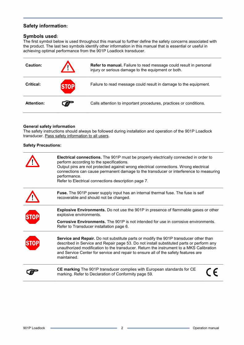
Safety information: Symbols used: The first symbol below is used throughout this manual to further define the safety concerns associated with the product. The last two symbols identify other information in this manual that is essential or useful in achieving optimal performance from the 901P Loadlock transducer. Caution:
Refer to manual. Failure to read message could result in personal injury or serious damage to the equipment or both.
Critical:
Failure to read message could result in damage to the equipment.
Attention:
Calls attention to important procedures, practices or conditions.
General safety information The safety instructions should always be followed during installation and operation of the 901P Loadlock transducer. Pass safety information to all users. Safety Precautions:
Electrical connections. The 901P must be properly electrically connected in order to perform according to the specifications. Output pins are not protected against wrong electrical connections. Wrong electrical connections can cause permanent damage to the transducer or interference to measuring performance. Refer to Electrical connections description page 7.
Fuse. The 901P power supply input has an internal thermal fuse. The fuse is self recoverable and should not be changed.
Explosive Environments. Do not use the 901P in presence of flammable gases or other explosive environments.
Corrosive Environments. The 901P is not intended for use in corrosive environments. Refer to Transducer installation page 6.
Service and Repair. Do not substitute parts or modify the 901P transducer other than described in Service and Repair page 53. Do not install substituted parts or perform any unauthorized modification to the transducer. Return the instrument to a MKS Calibration and Service Center for service and repair to ensure all of the safety features are maintained.
CE marking The 901P transducer complies with European standards for CE marking. Refer to Declaration of Conformity page 59.
901P Loadlock Operation manual
3
Unpacking Before unpacking your 901P Loadlock transducer, check all surfaces of the packing material for shipping damage. Inspect for visible damage. If found, notify the carrier immediately. Please be sure that your 901P package contains these items:
Part number Description 901P-xxxxx 901P Transducer 100017120 Short form manual 100017096 Documentation & Software CD
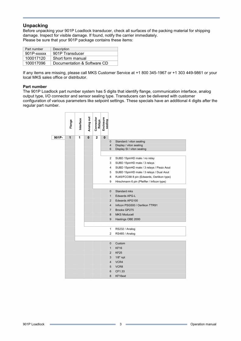
If any items are missing, please call MKS Customer Service at +1 800 345-1967 or +1 303 449-9861 or your local MKS sales office or distributor. Part number The 901P Loadlock part number system has 5 digits that identify flange, communication interface, analog output type, I/O connector and sensor sealing type. Transducers can be delivered with customer configuration of various parameters like setpoint settings. These specials have an additional 4 digits after the regular part number.
Flan
ge
Inte
rfac
e
Ana
log
out
Con
nect
or
Rel
ays
Encl
osur
e se
alin
g
901P- 1 1 0 2 0 - 0 Standard / viton sealing 4 Display / viton sealing 6 Display SI / viton sealing
2 SUBD 15pinHD male / no relay
3 SUBD 15pinHD male / 3 relays
4 SUBD 15pinHD male / 3 relays / Piezo Aout
5 SUBD 15pinHD male / 3 relays / Dual Aout
8 RJ45/FCC68 8 pin (Edwards, Oerlikon type)
9 Hirschmann 6 pin (Pfeiffer / Inficon type)
0 Standard mks
1 Edwards APG-L
2 Edwards APG100
4 Inficon PSG500 / Oerlikon TTR91
7 Brooks GP275
8 MKS Moducell
9 Hastings OBE 2000
1 RS232 / Analog
2 RS485 / Analog
0 Custom
1 KF16
2 KF25
3 1/8" npt
4 VCR4
5 VCR8
6 CF1.33
8 KF16ext

901P Loadlock Operation manual
4
Description The 901P Loadlock vacuum transducer offers a wide measuring range from 1×10⁻⁵ to 1000 Torr and is based on measurement of thermal conductivity and measurement of mechanical deflection of a silicon membrane.
The 901P is designed for semiconductor loadlock pressure controlling, but it can be used in a variety of applications as standalone unit or with the PDR900 display and controller unit. The transducer has RS232 or RS485 digital communication interface for setup of transducer parameters and to provide real time pressure measurement.
The 901P has up to three mechanical relays which can be used for process control such as interlocking valves or pumps. The analog voltage output can be interfaced to external analog equipment for pressure readout or control. Sensor technology The 901P transducer contains two separate sensor elements. The MicroPirani™ sensor element is based on measurement of thermal conductivity. The MicroPirani sensor consists of a silicon chip with a heated resistive element forming one surface of a cavity. A cover on top of the chip forms the other surface of the cavity. Due to the geometry of the sensor, convection cannot take place within the cavity and consequently the sensor is insensitive to mounting position. Gas molecules are passed by diffusion only to the heated element where the heat loss of the gas is measured. The Piezo sensor is based on measurement of mechanical deflection of a silicon membrane where one side of the membrane is exposed to ambient pressure and the other side is exposed to vacuum. The Piezo measures true differential pressure independent of gas composition and concentration. Both sensor elements are very robust and can withstand high G-forces and instant air inrush. Applications The 901P can be used in many different vacuum applications within the semiconductor, analytical and coating industries:
Loadlock pressure controlling General vacuum pressure measurement Fore line and roughing pressure measurement Gas backfilling measurement and controlling Mass spectrometer control Activation of UHV gauge System process control Sense abnormal pressure and take appropriate security measure using set point relays Control system pressure
Disposal (European Union only) The 901P transducer is manufactured according to the RoHS directive.
For the benefit of the environment, at the end of life of the 901P, it should not be disposed in the normal unsorted waste stream. It should be deposited at an appropriate collection point or facility to enable recovery or recycling.
901P Loadlock Operation manual
5
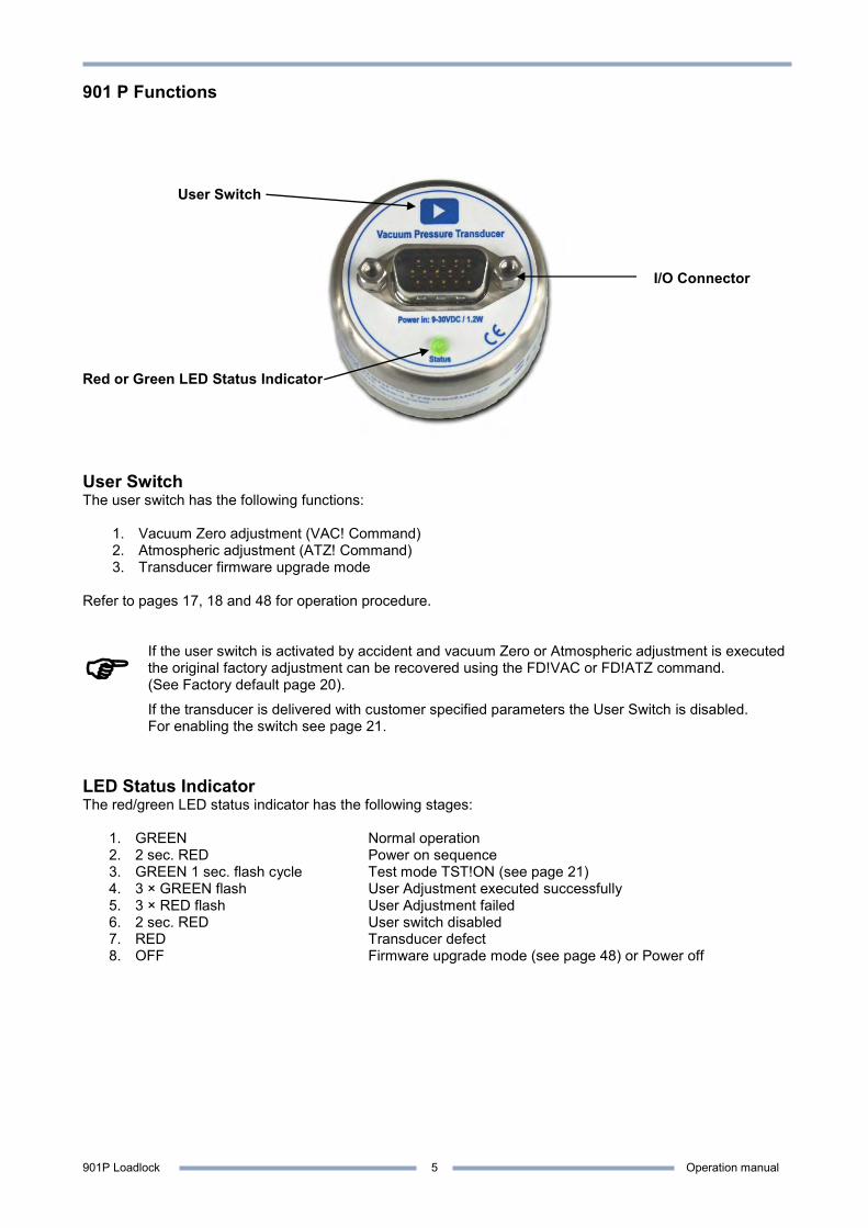
901 P Functions
User Switch I/O Connector
Red or Green LED Status Indicator User Switch The user switch has the following functions:
1. Vacuum Zero adjustment (VAC! Command) 2. Atmospheric adjustment (ATZ! Command) 3. Transducer firmware upgrade mode
Refer to pages 17, 18 and 48 for operation procedure.
If the user switch is activated by accident and vacuum Zero or Atmospheric adjustment is executed the original factory adjustment can be recovered using the FD!VAC or FD!ATZ command. (See Factory default page 20).
If the transducer is delivered with customer specified parameters the User Switch is disabled. For enabling the switch see page 21.
LED Status Indicator The red/green LED status indicator has the following stages:
1. GREEN Normal operation 2. 2 sec. RED Power on sequence 3. GREEN 1 sec. flash cycle Test mode TST!ON (see page 21) 4. 3 × GREEN flash User Adjustment executed successfully 5. 3 × RED flash User Adjustment failed 6. 2 sec. RED User switch disabled 7. RED Transducer defect 8. OFF Firmware upgrade mode (see page 48) or Power off
901P Loadlock Operation manual
6
Transducer installation (mechanical)
Do not use or install the 901P transducer where the following conditions occur: - Temperatures lower than 0 oC or higher than 40 oC - Corrosive or explosive gases - Direct sunlight or other heat sources
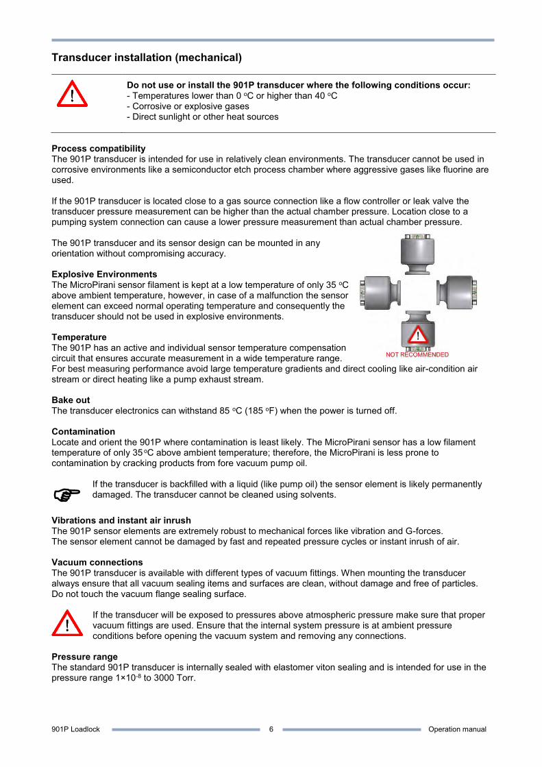
Process compatibility The 901P transducer is intended for use in relatively clean environments. The transducer cannot be used in corrosive environments like a semiconductor etch process chamber where aggressive gases like fluorine are used. If the 901P transducer is located close to a gas source connection like a flow controller or leak valve the transducer pressure measurement can be higher than the actual chamber pressure. Location close to a pumping system connection can cause a lower pressure measurement than actual chamber pressure. The 901P transducer and its sensor design can be mounted in any orientation without compromising accuracy. Explosive Environments The MicroPirani sensor filament is kept at a low temperature of only 35 oC above ambient temperature, however, in case of a malfunction the sensor element can exceed normal operating temperature and consequently the transducer should not be used in explosive environments. Temperature The 901P has an active and individual sensor temperature compensation circuit that ensures accurate measurement in a wide temperature range. For best measuring performance avoid large temperature gradients and direct cooling like air-condition air stream or direct heating like a pump exhaust stream. Bake out The transducer electronics can withstand 85 oC (185 oF) when the power is turned off. Contamination Locate and orient the 901P where contamination is least likely. The MicroPirani sensor has a low filament temperature of only 35 oC above ambient temperature; therefore, the MicroPirani is less prone to contamination by cracking products from fore vacuum pump oil.
If the transducer is backfilled with a liquid (like pump oil) the sensor element is likely permanently damaged. The transducer cannot be cleaned using solvents.
Vibrations and instant air inrush The 901P sensor elements are extremely robust to mechanical forces like vibration and G-forces. The sensor element cannot be damaged by fast and repeated pressure cycles or instant inrush of air. Vacuum connections The 901P transducer is available with different types of vacuum fittings. When mounting the transducer always ensure that all vacuum sealing items and surfaces are clean, without damage and free of particles. Do not touch the vacuum flange sealing surface.
If the transducer will be exposed to pressures above atmospheric pressure make sure that proper vacuum fittings are used. Ensure that the internal system pressure is at ambient pressure conditions before opening the vacuum system and removing any connections.
Pressure range The standard 901P transducer is internally sealed with elastomer viton sealing and is intended for use in the pressure range 1×10⁻⁸ to 3000 Torr.
901P Loadlock Operation manual
7
Transducer installation (electrical) The 901P is available with different input/output connectors. Use a cable with strain relief to ensure proper electrical connection and to reduce stress on the connectors.
Ensure a low impedance electrical connection between the 901P transducer body and the grounded vacuum system to shield the sensor from external electromagnetic sources. Ensure that the analog output is connected to a floating input.
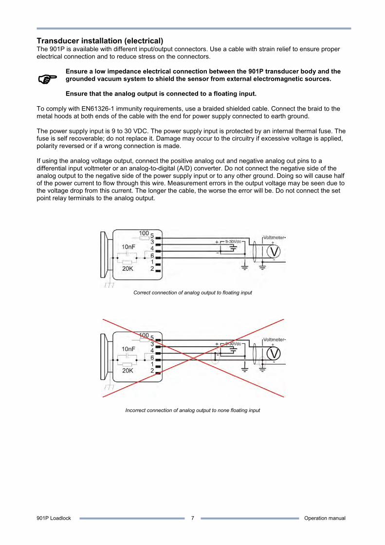
To comply with EN61326-1 immunity requirements, use a braided shielded cable. Connect the braid to the metal hoods at both ends of the cable with the end for power supply connected to earth ground. The power supply input is 9 to 30 VDC. The power supply input is protected by an internal thermal fuse. The fuse is self recoverable; do not replace it. Damage may occur to the circuitry if excessive voltage is applied, polarity reversed or if a wrong connection is made. If using the analog voltage output, connect the positive analog out and negative analog out pins to a differential input voltmeter or an analog-to-digital (A/D) converter. Do not connect the negative side of the analog output to the negative side of the power supply input or to any other ground. Doing so will cause half of the power current to flow through this wire. Measurement errors in the output voltage may be seen due to the voltage drop from this current. The longer the cable, the worse the error will be. Do not connect the set point relay terminals to the analog output.
Correct connection of analog output to floating input
Incorrect connection of analog output to none floating input
901P Loadlock Operation manual
8
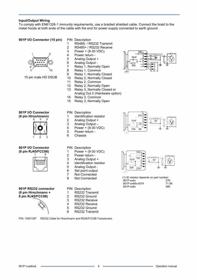
Input/Output Wiring To comply with EN61326-1 immunity requirements, use a braided shielded cable. Connect the braid to the metal hoods at both ends of the cable with the end for power supply connected to earth ground. 901P I/O Connector (15 pin)
15 pin male HD DSUB
PIN Description 1 RS485- / RS232 Transmit 2 RS485+ / RS232 Receive 3 Power + (9-30 VDC) 4 Power return - 5 Analog Output + 6 Analog Output - 7 Relay 1, Normally Open 8 Relay 1, Common 9 Relay 1, Normally Closed 10 Relay 2, Normally Closed 11 Relay 2, Common 12 Relay 2, Normally Open 13 Relay 3, Normally Closed or
Analog Out 2 (Hardware option) 14 Relay 3, Common 15 Relay 3, Normally Open
901P I/O Connector (6 pin Hirschmann)
PIN Description 1 Identification resistor 2 Analog Output + 3 Analog Output – 4 Power + (9-30 VDC) 5 Power return - 6 Chassis
901P I/O Connector (8 pin RJ45/FCC68)
PIN Description 1 Power + (9-30 VDC) 2 Power return - 3 Analog Output + 4 Identification resistor 5 Analog Output - 6 Set point output 7 Not Connected 8 Not Connected
901P RS232 connector (6 pin Hirschmann + 8 pin RJ45/FCC68)
PIN Description 1 RS232 Transmit 2 RS232 Ground 3 RS232 Receive 4 RS232 Receive 5 RS232 Ground 6 RS232 Transmit
P/N: 10001367 RS232 Cable for Hirschmann and RS45/FCC68 Transducers.
(1) ID resistor depends on part number: 901P-xx4x 27K 901P-xx48x-0074 71.5K 901P-xx8x 36K
901P Loadlock Operation manual
9
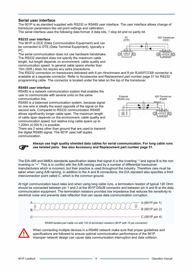
Serial user interface The 901P is as standard supplied with RS232 or RS485 user interface. The user interface allows change of transducer parameters like set point settings and calibration. The serial interface uses the following data format: 8 data bits, 1 stop bit and no parity bit. RS232 user interface The 901P is DCE (Data Communication Equipment) and can be connected to DTE (Data Terminal Equipment), typically a PC. The serial communication does not use hardware handshake. The RS232 standard does not specify the maximum cable length, but length depends on environment, cable quality and communication speed. In general cable spans shorter than 15m (50ft.) does not require any extra precautions.
The RS232 connection on transducers delivered with 6 pin Hirschmann and 8 pin RJ45/FCC68 connector is available at a separate connector. Refer to Accessories and Replacement part number page 51 for RS232 programming cable. The connector is located under the label on the top of the transducer. RS485 user interface RS485 is a network communication system that enables the user to communicate with several units on the same communication line. RS485 is a balanced communication system, because signal on one wire is ideally the exact opposite of the signal on the second wire. Compared to RS232 communication RS485 allows significantly longer cable span. The maximum length of cable span depends on the environment, cable quality and communication speed, but relative long cable spans up to 1,200m (4,000 ft.) is possible. There are 2 wires other than ground that are used to transmit the digital RS485 signal. The 901P uses half duplex communication.
Always use high quality shielded data cables for serial communication. For long cable runs use twisted pairs. See also Accessory and Replacement part number page 51.
The EIA-485 and NMEA standards specification states that signal A is the inverting “-“and signal B is the non inverting or “+”. This is in conflict with the A/B naming used by a number of differential transceiver manufacturers which is incorrect, but their practice is used throughout the industry. Therefore care must be taken when using A/B naming. In addition to the A and B connections, the EIA standard also specifies a third interconnection point called C, which is the common ground.
At high communication baud rates and when using long cable runs, a termination resistor of typical 120 Ohm should be connected between pin 1 and 2 at the 901P DSUB connector and between pin A and B at the data communication equipment. The termination resistors provides low impedance that reduces the sensitivity to electrical noise and prevents data reflection that can cause data communication corruption.
RS485 twisted pair cable run with 120 Ω terminator resistors (901P with 15 pin connector)
When connecting multiple devices in a RS485 network make sure that proper guidelines and specifications are followed to ensure optimal communication performance of the 901P. Improper network design can cause data communication interruption and data collision.
901P Loadlock Operation manual
10
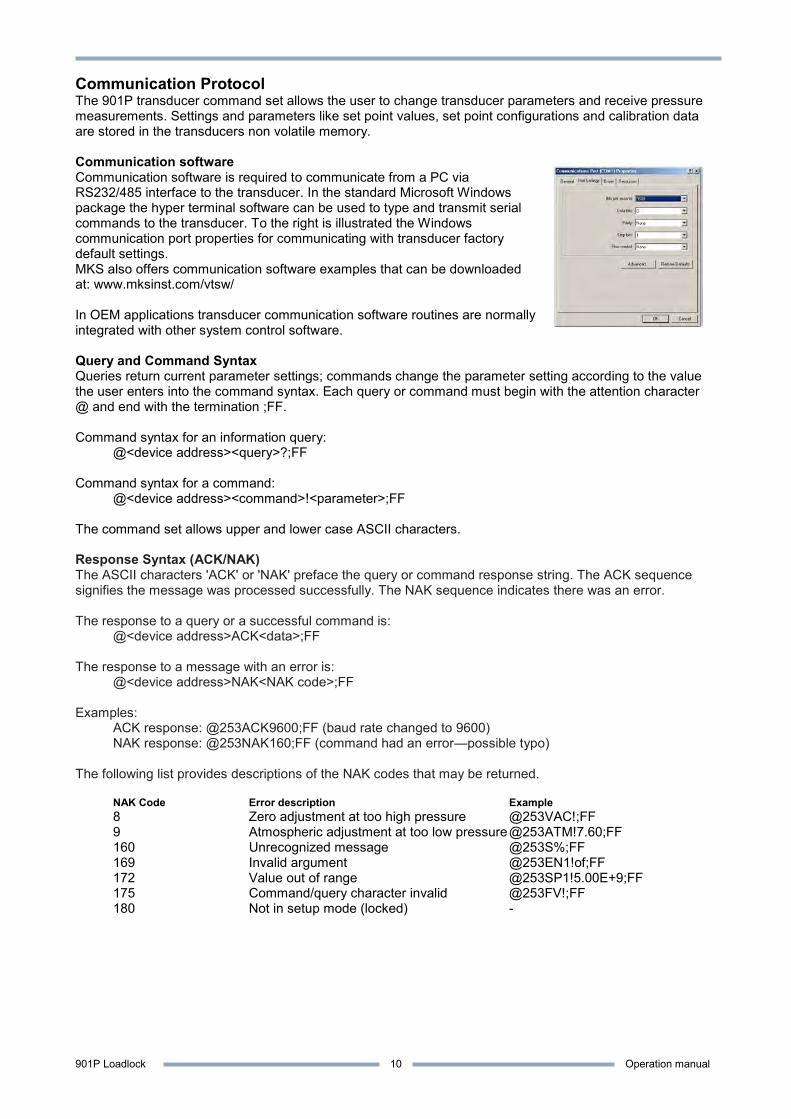
Communication Protocol The 901P transducer command set allows the user to change transducer parameters and receive pressure measurements. Settings and parameters like set point values, set point configurations and calibration data are stored in the transducers non volatile memory. Communication software Communication software is required to communicate from a PC via RS232/485 interface to the transducer. In the standard Microsoft Windows package the hyper terminal software can be used to type and transmit serial commands to the transducer. To the right is illustrated the Windows communication port properties for communicating with transducer factory default settings. MKS also offers communication software examples that can be downloaded at: www.mksinst.com/vtsw/ In OEM applications transducer communication software routines are normally integrated with other system control software. Query and Command Syntax Queries return current parameter settings; commands change the parameter setting according to the value the user enters into the command syntax. Each query or command must begin with the attention character @ and end with the termination ;FF. Command syntax for an information query: @<device address><query>?;FF Command syntax for a command: @<device address><command>!<parameter>;FF The command set allows upper and lower case ASCII characters. Response Syntax (ACK/NAK) The ASCII characters 'ACK' or 'NAK' preface the query or command response string. The ACK sequence signifies the message was processed successfully. The NAK sequence indicates there was an error. The response to a query or a successful command is: @<device address>ACK<data>;FF The response to a message with an error is: @<device address>NAK<NAK code>;FF Examples: ACK response: @253ACK9600;FF (baud rate changed to 9600) NAK response: @253NAK160;FF (command had an error—possible typo) The following list provides descriptions of the NAK codes that may be returned. NAK Code Error description Example 8 Zero adjustment at too high pressure @253VAC!;FF 9 Atmospheric adjustment at too low pressure @253ATM!7.60;FF 160 Unrecognized message @253S%;FF 169 Invalid argument @253EN1!of;FF 172 Value out of range @253SP1!5.00E+9;FF 175 Command/query character invalid @253FV!;FF 180 Not in setup mode (locked) -
901P Loadlock Operation manual
11
Baud rate The baud rate represents the communication speed. The 901P supports 4800, 9600, 19200, 38400, 57600, 115200 and 230400 baud rates. The transducer is always delivered with 9600 bps factory default baud rate. Change of Baud rate: Command: @253BR!19200;FF Command values: 4800, 9600, 19200, 38400, 57600, 115200, 230400 Command reply: @253ACK19200;FF Factory default: 9600 The transducer will reply in the current baud rate and then change to the new value. Addressing The transducer uses an addressable communication protocol that allows multiple MKS 900 Series transducer devices to be connected in a RS485 network. The address is required in both RS232 and RS485 communication. The address can be set from 001 to 253. Address 254 and 255 are universal addresses, which can be used to broadcast a command to all devices on the network. Commands sent with address 254 will be executed by all transducers on the network and all transducers will transmit a reply. Commands sent with address 255 will be executed by all transducers on the network, but the transducers will not transmit replies. For example, use address 254 to communicate with a device if its address is unknown. Change of Address: Command: @253AD!123;FF Command values: 001 to 253 Command reply: @253ACK123;FF Query: @253AD?;FF Query reply: @253ACK253;FF Factory default: 253 Communication delay (RS485) The 901P half duplex RS485 interface requires that data is transmitted and received on the same communication line. Some RS485 transceiver equipment have a settling time when changing from transmit to receive mode. If the transducer replies too fast the first character(s) will not be received as the following example illustrates: Sending pressure request: @254PR1?;FF Receiving data: 23E-4;FF (Correct data: @253ACK1.23E-4;FF) The RS delay introduces a baud rate dependent delay between receive and transmit sequence to prevent loss of data in the receiving string. Communication delay: Command: @253RSD!ON;FF Command values: ON, OFF Command reply: @253ACKON;FF Query: @253RSD?;FF Query reply: @253ACKON;FF Factory default: ON
901P Loadlock Operation manual
12
Setpoint relays The 901P can be ordered with 3 mechanical relays that can be used for controlling external process equipment. The relay has closing and breaking contacts and the contacts are rated 30 VDC, 1A resistive load. If the transducer is supplied without setpoint relays, the setpoint commands can still be accessed. Refer to part number definition page 3 to verify if setpoint relays are included. Inductive relay load Special precautions should be taken when driving inductive loads with the relay contact. When an inductive load like a solenoid is energized, the in-rush current is significant higher than the regular load current. In-rush currents exceeding the relay contact rating can cause reduction of relay contact life time or contact reliability. When a solenoid is de-energized, the collapsing magnetic field can cause significant voltage spikes. These spikes can couple capacitive from cable to cable and interfere with measuring electronics or transducer signal.
Driving inductive loads via the setpoint relay contacts requires de-energizing spike protection. Inadequate protection can cause permanent damage to the transducer or interfere with the analog output signal. Always ensure that inductive in-rush currents do not exceed relay contact rating.
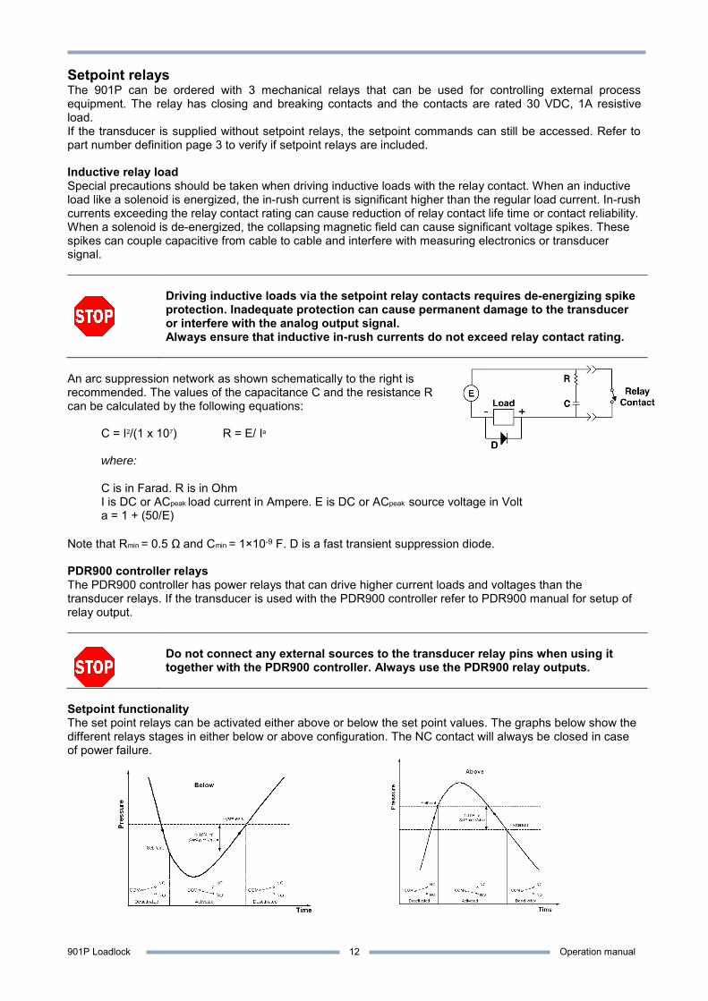
An arc suppression network as shown schematically to the right is recommended. The values of the capacitance C and the resistance R can be calculated by the following equations:
C = I2/(1 x 107) R = E/ Ia where: C is in Farad. R is in Ohm I is DC or ACpeak load current in Ampere. E is DC or ACpeak source voltage in Volt a = 1 + (50/E) Note that Rmin = 0.5 Ωand Cmin = 1×10⁻⁹ F. D is a fast transient suppression diode. PDR900 controller relays The PDR900 controller has power relays that can drive higher current loads and voltages than the transducer relays. If the transducer is used with the PDR900 controller refer to PDR900 manual for setup of relay output.
Do not connect any external sources to the transducer relay pins when using it together with the PDR900 controller. Always use the PDR900 relay outputs.
Setpoint functionality The set point relays can be activated either above or below the set point values. The graphs below show the different relays stages in either below or above configuration. The NC contact will always be closed in case of power failure.
901P Loadlock Operation manual
13
Setpoint 1 value
-5.00E+1 Torr
Hysteresis 1
-4.00E+1 Torr
Setp.1 Direction
Below
Setp.1 Enable
PZ
When using the setpoint relay to control process equipment, always take appropriate precautions to prevent system damage in case of transducer power failure. The NC contact will be closed in case of transducer power failure.
If the transducer is supplied as a special version (P/N: 901P-xxxxx-xxxx) with pre-configured parameters such as setpoint settings, the setup is per default locked. The transducer will reply with error code “NAK180” if the user tries to change parameters. To change pre-configured parameters refer to unlock procedure page 21.
Setpoint setup by Serial interface The correct procedure for setting up set point parameters are:
1. Enter set point value -5.00E+1 Torr Command: @253SP1!-5.00E+1;FF Reply: @253ACK-5.00E+1;FF
2. Select set point direction (ABOVE/BELOW) Command: @253SD1!BELOW;FF Reply: @253ACKBELOW;FF
3. Enter set point hysteresis value, if other than default +/- 10% of set point value is required. Command: @253SH1!-4.00E+1;FF Reply: @253ACK-4.00E+1;FF
4. Enable set point (OFF, ABS, PZ) Command: @253EN1!PZ;FF Reply: @253ACKPZ;FF
Setpoint setup by PDR900 Controller
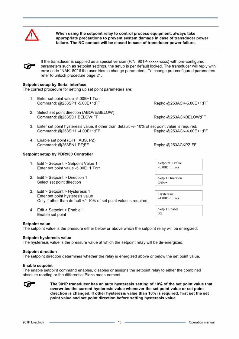
1. Edit > Setpoint > Setpoint Value 1 Enter set point value -5.00E+1 Torr
2. Edit > Setpoint > Direction 1 Select set point direction
3. Edit > Setpoint > Hysteresis 1 Enter set point hysteresis value Only if other than default +/- 10% of set point value is required.
4. Edit > Setpoint > Enable 1 Enable set point
Setpoint value The setpoint value is the pressure either below or above which the setpoint relay will be energized. Setpoint hysteresis value The hysteresis value is the pressure value at which the setpoint relay will be de-energized. Setpoint direction The setpoint direction determines whether the relay is energized above or below the set point value. Enable setpoint The enable setpoint command enables, disables or assigns the setpoint relay to either the combined absolute reading or the differential Piezo measurement.
The 901P transducer has an auto hysteresis setting of 10% of the set point value that overwrites the current hysteresis value whenever the set point value or set point direction is changed. If other hysteresis value than 10% is required, first set the set point value and set point direction before setting hysteresis value.
901P Loadlock Operation manual
14
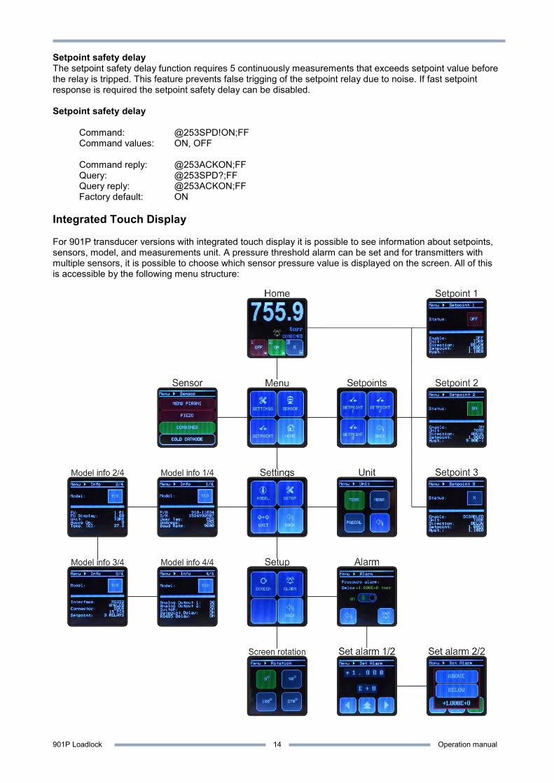
Setpoint safety delay The setpoint safety delay function requires 5 continuously measurements that exceeds setpoint value before the relay is tripped. This feature prevents false trigging of the setpoint relay due to noise. If fast setpoint response is required the setpoint safety delay can be disabled. Setpoint safety delay Command: @253SPD!ON;FF Command values: ON, OFF Command reply: @253ACKON;FF Query: @253SPD?;FF Query reply: @253ACKON;FF Factory default: ON Integrated Touch Display For 901P transducer versions with integrated touch display it is possible to see information about setpoints, sensors, model, and measurements unit. A pressure threshold alarm can be set and for transmitters with multiple sensors, it is possible to choose which sensor pressure value is displayed on the screen. All of this is accessible by the following menu structure:

901P Loadlock Operation manual
15
Using the integrated touch display: When the transducer is turned on, the initializing screen shows the transducer name while starting up. After start-up, the screen automatically switches to the Main screen. To access the Menu, push anywhere on the Main screen. The following table shows the different menus and options available: Display-screen Information Start-up MKS logo and transducer model Home The Home screen shows the current pressure, the transducer model, the status of the setpoints, the
triggering direction of each setpoint and shows if an alarm is enabled. The setpoint buttons and unit text give quick access to the separate Setpoint-screens and Unit screen respectively.
Menu The general Menu contains 4 buttons which lead to: Settings, Sensor, Setpoints menu and Home.
Settings The Settings menu contains 4 buttons which lead to: Model info, Setup menu, Unit and Back
Setup The Setup menu contains 3 buttons which lead to: Screen rotation, Alarm and Back
Sensor The Sensor screen shows which sensor’s measurement is displayed on the Home screen (green marked sensor).
Setpoints menu The Setpoint menu contains 4 buttons which lead to: Setpoint 1, Setpoint 2, Setpoint 3 and Back (to Menu)
Setpoint screen Setpoint 1,2 or 3 Each Setpoint screen shows the setpoint status, the pressure unit, pressure triggering direction, setpoint value and hysteresis value. The setpoint status is indicated by:
X Setpoint disabled (Grey) PIR Setpoint enabled ON/OFF, MEMS-Pirani dependent (Green/Red) PZ Setpoint enabled ON/OFF, Piezo dependent (Green/Red) CMB Setpoint enabled ON/OFF, Combined sensor dependent (Green/Red)
If the Setpoint screen is accessed via the Setpoint menu, pressing the screen will lead back to the same menu. If accessed via the quick-access buttons on the Main screen, pressing the screen will lead back to the Main screen.
Model info The Model info screen shows the transducer type and model number and each screen has different extra information. Press the screen to toggle through the different info screens and eventually go back to Settings. Model info (1/4) Model info (2/4) Model info (3/4) Model info (3/4) Transducer P/N
Gas type Interface type User switch ON/OFF
Serial number Transducer firmware version
Connector type Setpoint delay 50ms ON/OFF
User tag Display firmware version
Number of available relays
Relay communication delay ON/OFF
Communication adress RS485 testing Temperature (°C)
Baud rate Pressure unit Transducer ON-time Unit The Unit screen displays the current pressure unit and gives the possibility to change the pressure unit
between Torr, Milibar or Pascal. Screen rotation The Screen Rotation screen displays the current screen orientation and enables the operator to rotate
the screen in four directions. Alarm A visual alarm can be set at a certain pressure.
Press the green or red button to enable or disable the alarm. Press Set to change the alarm pressure value and triggering direction. Set Alarm (1/2) Setting pressure threshold: The alarm value is set by selecting a digit (left and right arrow) and cycling through the numbers 0-9 and +/- (press up arrow or screen) To accept, press right arrow until a green checkmark appears. Press again to proceed. To cancel, press left arrow until a red arrow appears. Press again to proceed.
Set Alarm (2/2) When the alarm is set, the operator selects whether the alarm triggers above or below the given value.
901P Loadlock Operation manual
16
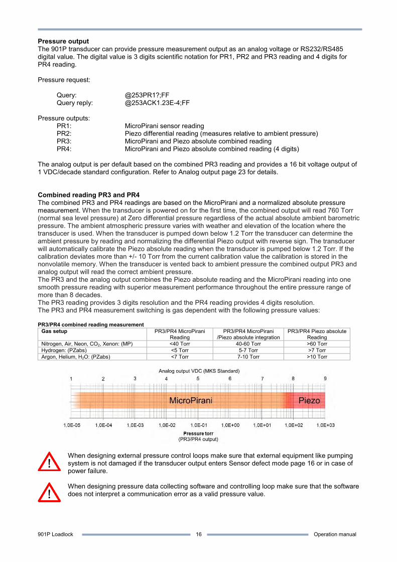
Pressure output The 901P transducer can provide pressure measurement output as an analog voltage or RS232/RS485 digital value. The digital value is 3 digits scientific notation for PR1, PR2 and PR3 reading and 4 digits for PR4 reading. Pressure request: Query: @253PR1?;FF Query reply: @253ACK1.23E-4;FF Pressure outputs: PR1: MicroPirani sensor reading PR2: Piezo differential reading (measures relative to ambient pressure) PR3: MicroPirani and Piezo absolute combined reading PR4: MicroPirani and Piezo absolute combined reading (4 digits) The analog output is per default based on the combined PR3 reading and provides a 16 bit voltage output of 1 VDC/decade standard configuration. Refer to Analog output page 23 for details. Combined reading PR3 and PR4 The combined PR3 and PR4 readings are based on the MicroPirani and a normalized absolute pressure measurement. When the transducer is powered on for the first time, the combined output will read 760 Torr (normal sea level pressure) at Zero differential pressure regardless of the actual absolute ambient barometric pressure. The ambient atmospheric pressure varies with weather and elevation of the location where the transducer is used. When the transducer is pumped down below 1.2 Torr the transducer can determine the ambient pressure by reading and normalizing the differential Piezo output with reverse sign. The transducer will automatically calibrate the Piezo absolute reading when the transducer is pumped below 1.2 Torr. If the calibration deviates more than +/- 10 Torr from the current calibration value the calibration is stored in the nonvolatile memory. When the transducer is vented back to ambient pressure the combined output PR3 and analog output will read the correct ambient pressure. The PR3 and the analog output combines the Piezo absolute reading and the MicroPirani reading into one smooth pressure reading with superior measurement performance throughout the entire pressure range of more than 8 decades. The PR3 reading provides 3 digits resolution and the PR4 reading provides 4 digits resolution. The PR3 and PR4 measurement switching is gas dependent with the following pressure values: PR3/PR4 combined reading measurement
Gas setup PR3/PR4 MicroPirani Reading
PR3/PR4 MicroPirani /Piezo absolute integration
PR3/PR4 Piezo absolute Reading
Nitrogen, Air, Neon, CO2, Xenon: (MP) <40 Torr 40-60 Torr >60 Torr Hydrogen: (PZabs) <5 Torr 5-7 Torr >7 Torr Argon, Helium, H2O: (PZabs) <7 Torr 7-10 Torr >10 Torr
When designing external pressure control loops make sure that external equipment like pumping system is not damaged if the transducer output enters Sensor defect mode page 16 or in case of power failure.
When designing pressure data collecting software and controlling loop make sure that the software does not interpret a communication error as a valid pressure value.

901P Loadlock Operation manual
17
Resolution The digital pressure output can provide 3 digit or 4 digit values; however, the resolution is limited in certain parts of the measuring range. 1.00E-5 to 1.00E-4 Torr 1 digit resolution 1.000E-5 1.00E-4 to 1.00E-3 Torr 2 digit resolution 1.200E-4 1.00E-3 to 900 Torr 3 or 4 digit resolution 1.234E-3 Measuring noise External sources can interfere with the sensor signal and cause noise in the signal. The low measuring range is most sensitive to measuring noise due to low signal levels.
901P Loadlock Operation manual
18
Calibration and adjustment The 901P is factory calibrated when delivered and in most applications further calibration is not required. If the sensor element has been contaminated or damaged by process gases, adjustment of zero and full scale can be executed to compensate for measurement errors.
The 901P is per factory default calibrated for reading in Nitrogen gas. When exposed to atmospheric air the MicroPirani sensor (PR1) will read higher values, typical 900 Torr at ambient pressure.
Accuracy and repeatability The 901P measuring accuracy is specified as transducer reading ± a percentage of the actual pressure. The basic measuring accuracy is factory calibrated and cannot be user adjusted. The repeatability specification is the transducers ability to repeat the same measurement value after multiple pressure cycles. Refer to the transducer specification page 53 for actual values. Gas calibration The 901P is based on measurement of thermal conductivity of the gas and consequently its reading depends on the gas and gas concentration. The 901P is per default set to Nitrogen calibration; however, the transducer has calibration curves for several common gases. Change of gas calibration setup: Command: @253GT!ARGON;FF Command values: NITROGEN, ARGON, HELIUM, HYDROGEN, H2O, NEON, CO2, XENON Command reply: @253ACKARGON;FF Query: @253GT?;FF Query reply: @253ACKARGON;FF Factory default: Nitrogen Pressure unit calibration The transducer can provide digital and analog output in Torr, mbar and Pascal pressure units. When changing unit all parameters like setpoint settings are automatically converted to the new unit, so it will represent the same pressure level. All pressure parameters must be entered in the actual transducer unit setting. Change of pressure unit calibration setup: Command: @253U!PASCAL;FF Command values: TORR, MBAR, PASCAL Command reply: @253ACKPASCAL;FF Query: @253U?;FF Query reply: @253ACKPASCAL;FF Factory default: Pascal The Torr unit is most common in the US and mbar is most common in Europe. Pascal is the official pressure unit as specified by SI (from the French Le Système International d'Unités) and is widely used in Asia. MicroPirani Zero Adjustment by serial interface The zero adjustment function changes the MicroPirani measurement offset at low pressure. Temporary or permanent shift in zero offset can be caused by contamination, corrosion, electrical noise interference and temperature.
Zero adjustment only changes the low measuring range and will have no influence on measuring errors in the range from 1×10⁻² and above.
If the transducer is reading 8.00E-5 Torr at an actual pressure of 1.00E-5 Torr, the offset error is +7.00E-5 or 700% error of actual pressure. At two decades higher pressure of 1.00E-3 Torr the offset error is a factor 100 lower when measured of the actual value, so the 7.00E-5 Torr offset will cause a 7% error at 1.00E-3 Torr.
To obtain best measuring performance, the transducer should be evacuated to a pressure below 8×10⁻⁶ Torr before executing zero adjustment. Zero adjustment can be executed at higher pressures, but this can cause inaccurate
901P Loadlock Operation manual
19
reading below the zero adjustment value.
Executing zero adjustment. (Evacuate the transducer to a pressure below 8×10⁻⁶ Torr) Command: @253VAC!5.00E-5;FF Command values: None, 1.00E-5 to 5.00E-3 Command reply: @253ACK;FF Query: @253VAC?;FF Query reply: @253ACK5E-5;FF Reset to default: @253FD!VAC;FF Factory default: Factory adjustment value Sensor value too high: @253NAK8;FF After execution of zero adjustment the PR1 reading will be 1×10⁻⁵ Torr. If the pressure measured by the transducer is higher than approximately 1×10⁻² Torr then the zero adjustment cannot be executed. This indicates that the transducer is contaminated and should be serviced. See page 53 for Service and Maintenance procedures. The query feature reads the delta value between the user offset value and factory default value. This can be used to monitor the positive and negative offset trend regardless of how many times the zero adjustment is executed. Zero Adjustment by use of the User switch The transducer can also be adjusted by activating the user switch. When using the switch the transducer must be evacuated to a pressure below 8×10⁻⁶ Torr. Press down the switch for 2 seconds and the LED will flash green three times to acknowledge the zero adjustment has been executed successfully. The LED will flash red three times if the adjustment has failed. MicroPirani Atmospheric adjustment The MicroPirani atmospheric adjustment allows the user to adjust the MicroPirani full scale reading. Vent the transducer to atmospheric pressure using the gas that corresponds to the gas calibration setup. Atmospheric adjustment can only be executed with air or Nitrogen.
Atmospheric adjustment only changes the high measuring range and will have no influence on measuring errors in the range below 10 Torr.
Executing atmospheric adjustment. (Vent transducer to Nitrogen or air pressure of 500-780 Torr) Command: @253ATM!7.60E+2;FF Command values: 5.00E+2 to 7.80E+2 Command reply: @253ACK;FF Query: @253ATM?;FF Query reply: @253ACK1.00E+2;FF Reset to default: @FD!ATM;FF Factory default: Factory adjustment value The query feature reads the delta value between the user atmospheric adjustment value and the factory default value.

901P Loadlock Operation manual
20
Piezo Atmospheric zero adjustment The Piezo atmospheric adjustment allows the user to adjust zero offset error for the differential measurement. Executing Piezo zero adjustment. (Place the transducer in atmospheric pressure) Command: @253ATZ!;FF Command values: None Command reply: @253ACK;FF Query: @253ATZ?;FF Query reply: @253ACK5E-1;FF Reset to default: @253FD!ATZ;FF Factory default: Factory adjustment value Sensor value too high: @253NAK8;FF After execution of Piezo atmospheric zero adjustment the PR2 reading will be ±1×10⁻¹ Torr. Piezo Atmospheric zero adjustment by use of the switch The Piezo atmospheric zero adjustment can also be adjusted by use of the user switch. Expose the transducer to atmospheric pressure and press down the User switch for 2 seconds and the LED will flash green three times to acknowledge the atmospheric adjustment has been executed successfully. The LED will flash red three times if the adjustment has failed. Piezo absolute Atmospheric output adjustment The Piezo atmospheric adjustment allows the user to adjust the absolute Piezo reading at zero differential pressure. The Piezo absolute output adjustment is automatically adjusted whenever the pressure measured by the MicroPirani is lower than 1.2 Torr. If the value deviates more than ±10 Torr of the current value ATD value the ATD value will be overwritten in the non volatile memory. Executing Piezo absolute output adjustment. Command: @253ATD!;FF Command values: 4.00E+2 to 8.00E+2 Command reply: @253ACK;FF Reset to default: @253FD!ATD;FF Factory default: Factory adjustment value Sensor value to high: @253NAK8;FF After execution of Piezo atmospheric zero adjustment, the PR3 reading will read the entered value at zero differential pressure. Piezo differential full scale adjustment The ATS command sets the full scale reading for the differential Piezo. Enter the applied pressure in the range from 100 to 760 Torr. Executing Piezo differential full scale adjustment. Command: @253ATS!1.00E+2;FF Command values: 1.00E+2 to 7.60E+2 Command reply: @253ACK;FF Reset to default: @253FD!ATS;FF Factory default: Factory adjustment value Sensor value to high: @253NAK8;FF
901P Loadlock Operation manual
21
Factory default The transducer is per factory default delivered with parameters and setup as listed below. If the transducer is delivered with customer preconfigured parameters the values are different than listed below and the parameters will be locked per default. Communication parameters: Description Command Parameter FD! FD!ALL Address: AD! 253 - × Baud rate: BR! 9600 - × Communication delay: RSD! ON - × Transducer parameters: Description Command Parameter FD! FD!ALL Test mode (LED flash): TST! OFF × × User tag: UT! MKS - × Set point 1 value: SP1! 1.00E0 - × Set point 1 hysteresis value: SH1! 1.10E0 - × Set point 1 direction: SD1! BELOW - × Set point 1 enable: EN1! OFF - × Set point 2 value: SP1! 1.00E0 - × Set point 2 hysteresis value: SH1! 1.10E0 - × Set point 2 direction: SD1! BELOW - × Set point 2 enable: EN1! OFF - × Set point 3 value: SP1! 1.00E0 - × Set point 3 hysteresis value: SH1! 1.10E0 - × Set point 3 direction: SD1! BELOW - × Set point 3 enable: EN1! OFF - × Setpoint safety delay SPD! ON - × Switch enable: SW! ON - × Analog out 1: AO1! 10 (1) - × Analog out 2: AO2! 10 - × (1) If the transducer is delivered with other analog output than standard mks (part number specified), then the factory default value will be specified by the specials part number. Calibration setup: Description Command Parameter FD! FD!ALL Gas calibration: GT! NITROGEN × × MP Vacuum adjustment: VAC! Factory adjustment value × × MP Span atmospheric adjustment: ATM! Factory adjustment value × × PZ atmospheric zero adjust: ATZ! Factory adjustment value × × PZ positive full scale adjustment: ATS! Factory adjustment value × × PZ absolute calibration: ATD! 760 Torr × × Pressure unit: U! TORR - × Resetting to factory default The factory default command resets all or certain parameters of the 901P to factory default settings as listed above. If other digital communication setup than factory default values are used, then the communication will be lost after execution of factory default and the transceiver equipment should be set to transducer values.
The factory default command resets parameters to default values and consequently user adjustments, setup and factory configured parameters are lost. Use with caution!
Command: @253FD!ALL;FF Command values: None, ALL, UNLOCK, LOCK, VAC, ATM, ATZ, SPN Command reply: @253ACK;FF
901P Loadlock Operation manual
22
Transducer lock function To ensure that no unauthorized personal are able to change transducer setup and parameters, the transducer lock function can prevent direct access to parameter changes. Transducers delivered with pre-configured custom specified parameters (special part number) are per default locked and will reply with “NAK180”, if the user tries to change locked parameters. The unlock procedure must be executed to change these parameters. Disable lock function command: Command: @253FD!UNLOCK;FF Command reply: @253ACK;FF Enable lock function command: Command: @253FD!LOCK;FF Command reply: @253ACK;FF Standard transducer (7 digits part number: 901P-xxxx) Factory default: Transducer unlocked Special configuration transducer (11 digits part number: 901P-xxxx-xxxx) Factory default: Transducer locked
If the transducer is delivered with special configuration, the lock function will only be temporally disabled and will be enabled again after cycling power cycle or executing the enable lock command.
The 901P transducer can be delivered with factory locked tamperproof settings for safety interlock applications. This option is defined in the special settings. If delivered with factory lock the transducer settings can only by changed by return of gauge to MKS.
User Switch Command The User Switch function can be disabled to prevent accidental execution of zero and atmospheric adjustments. Command: @253SW!OFF;FF Command values: ON,OFF Command reply: @253ACK;FF Query: @253SW?;FF Query reply: @253ACKON;FF Factory default: ON Transducer test The transducer test command can be used to visually indentify a transducer. If the test mode is enabled the LED will flash with a 1 sec. cycle. Command: @253TST!ON;FF Command values: ON,OFF Command reply: @253ACK;FF Query: @253TST?;FF Query reply: @253ACKON;FF Factory default: OFF

901P Loadlock Operation manual
23
Status Query Commands Query replies are examples that might be different from actual transducer reply. Device Type - DT Specifies transducer device type name:
Query: @253DT?;FF Query reply: @253ACKLOADLOCK;FF
Firmware Version - FV Specifies transducer firmware version: Query: @253FV?;FF Query reply: @253ACK1.00;FF
Hardware Version - HV Specifies transducer hardware version: Query: @253HV?;FF Query reply: @253ACKA;FF
Manufacturer - MF Specifies transducer manufacturer: Query: @253MF?;FF Query reply: @253ACKMKS;FF
Model - MD Specifies transducer model number: Query: @253MD?;FF Query reply: @253ACK901P;FF Part Number - PN Specifies transducer part number:
Query: @253PN?;FF Query reply: @253ACK901P-11030;FF
Serial Number - SN Specifies transducer serial number: Query: @253SN?;FF Query reply: @253ACK0825123456;FF
Time ON - TIM The TIM command returns the number of hours the transducer has been on: Query: @253TIM?;FF Query reply: @253ACK123;FF
Temperature - TEM The TEM command returns the MicroPirani on chip sensor temperature oC within ±3 oC. Query: @253TEM?;FF Query reply: @253ACK2.50E+1;FF
Transducer Status - T The T command returns the MicroPirani sensor status as O for OK, M for MicroPirani fail or Z for Piezo fail. Query: @253T?;FF Query reply: @253ACKO;FF
901P Loadlock Operation manual
24
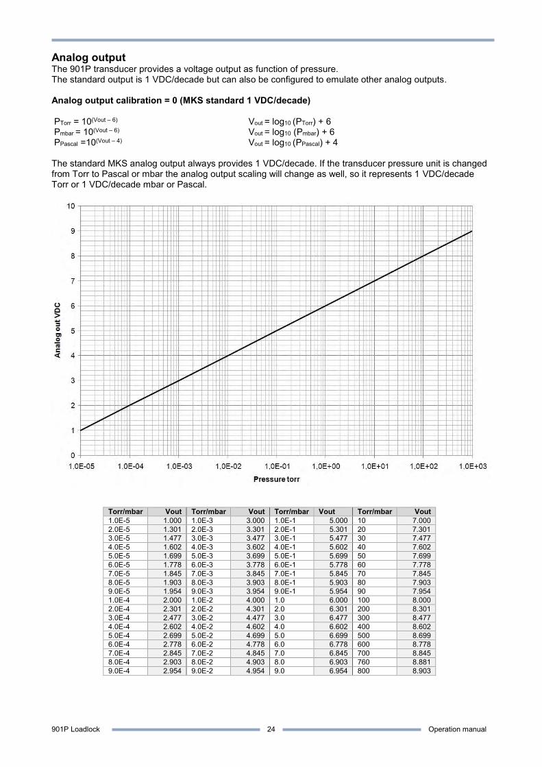
Analog output The 901P transducer provides a voltage output as function of pressure. The standard output is 1 VDC/decade but can also be configured to emulate other analog outputs. Analog output calibration = 0 (MKS standard 1 VDC/decade) PTorr = 10(Vout – 6) Vout = log10 (PTorr) + 6 Pmbar = 10(Vout – 6) Vout = log10 (Pmbar) + 6 PPascal =10(Vout – 4) Vout = log10 (PPascal) + 4 The standard MKS analog output always provides 1 VDC/decade. If the transducer pressure unit is changed from Torr to Pascal or mbar the analog output scaling will change as well, so it represents 1 VDC/decade Torr or 1 VDC/decade mbar or Pascal.
Torr/mbar Vout Torr/mbar Vout Torr/mbar Vout Torr/mbar Vout 1.0E-5 1.000 1.0E-3 3.000 1.0E-1 5.000 10 7.000 2.0E-5 1.301 2.0E-3 3.301 2.0E-1 5.301 20 7.301 3.0E-5 1.477 3.0E-3 3.477 3.0E-1 5.477 30 7.477 4.0E-5 1.602 4.0E-3 3.602 4.0E-1 5.602 40 7.602 5.0E-5 1.699 5.0E-3 3.699 5.0E-1 5.699 50 7.699 6.0E-5 1.778 6.0E-3 3.778 6.0E-1 5.778 60 7.778 7.0E-5 1.845 7.0E-3 3.845 7.0E-1 5.845 70 7.845 8.0E-5 1.903 8.0E-3 3.903 8.0E-1 5.903 80 7.903 9.0E-5 1.954 9.0E-3 3.954 9.0E-1 5.954 90 7.954 1.0E-4 2.000 1.0E-2 4.000 1.0 6.000 100 8.000 2.0E-4 2.301 2.0E-2 4.301 2.0 6.301 200 8.301 3.0E-4 2.477 3.0E-2 4.477 3.0 6.477 300 8.477 4.0E-4 2.602 4.0E-2 4.602 4.0 6.602 400 8.602 5.0E-4 2.699 5.0E-2 4.699 5.0 6.699 500 8.699 6.0E-4 2.778 6.0E-2 4.778 6.0 6.778 600 8.778 7.0E-4 2.845 7.0E-2 4.845 7.0 6.845 700 8.845 8.0E-4 2.903 8.0E-2 4.903 8.0 6.903 760 8.881 9.0E-4 2.954 9.0E-2 4.954 9.0 6.954 800 8.903
901P Loadlock Operation manual
25
Analog output setup The 901P can emulate analog voltage outputs from other vacuum transducers. The 901P analog output can be assigned to the MicroPirani sensor measurement (PR1), Piezo Differential sensor measurement (PR2) and the combined Piezo/MicroPirani reading (PR3). This is set by the first digit. The second and third digit represents the analog output calibration. The primary analog output provides 16 bit resolution.
Due to curve form and limits, some of the alternative analog outputs will cause loss of measuring range and accuracy. For best performance use the standard MKS analog output. Change of analog output setup does not interfere on digital reading.
Change of analog output setup:
Command: @253AO1!15;FF Command values: 10 to 319 (xy) First digit (x) 1 = PR1 (MicroPirani pressure value assignment) 2 = PR2 (Piezo pressure value assignment) 3 = PR3 (Combined pressure value assignment) Second digit (y) 0 = MKS Standard (1 VDC/decade) 1 = Edwards APG-L (1.99 -10 VDC) 2 = Edwards APG100 3 = Edwards WRG 4 = Inficon PSG500 /Oerlikon/Leybold TTR91 5 = Inficon MPG400 / Pfeiffer PKR251 6 = Inficon BPG400 / MKS 999 Quattro 7 = Brooks / Granville Phillips GP275 8 = MKS Moducell 325 9 = MKS Moducell 325 (x3) 10 = MKS Baratron 0.1 Torr (0-10 VDC) 11 = MKS Baratron 1 Torr (0-10 VDC) / Hasting 2002OBE, Channel 2 12 = MKS Baratron 10 Torr (0-10 VDC) 13 = MKS Baratron 100 Torr (0-10 VDC) 14 = MKS Baratron 1000 Torr (0-10 VDC) / Hasting 2002OBE, Channel 1 15 = Piezo differential output 16 = Edwards AIM-S /-SL 17 = Edwards AIM-X / XL 18 = Pfeiffer IKR251 19 = Pfeiffer TPR 265 20 = OBE Channel 2 special 21 = Edwards DV6M 22 = Edwards APG-M 23 = Brooks / Granville Phillips GP275 (0-9VDC) 24 = MT 241.1 25 = Brooks / Granville Phillips GP275 (0-5.6VDC) 26 = Edwards APG100-LC 27 = Edwards APG100M 28 = MKS 907 29 = K6080-06 30 = Inficon PEG100 31 = Varian Eyesys 32 = Alcatel TA111 33 = MKS 685
Command reply: @253ACK105;FF Query: @253AO1?;FF Query reply: @253ACK105;FF Factory default: 30

901P Loadlock Operation manual
26
Dual analog output The 901P is available with dual analog output which can be used to provide an alternative output for amplification of range or to emulate another transducer type while still using the MKS standard output. This feature is a hardware option and must be specially ordered. Refer to part number specifications page 3. The secondary analog output provides 12 bit resolution.
Command: @253AO2!15;FF Command values: 10 to 319 (xy) First digit (x) Use same parameters as primary analog output Second digit (y) Use same parameters as primary analog output Command reply: @253ACK105;FF Query: @253AO2?;FF Query reply: @253ACK105;FF Factory default: 10
901P Loadlock Operation manual
27
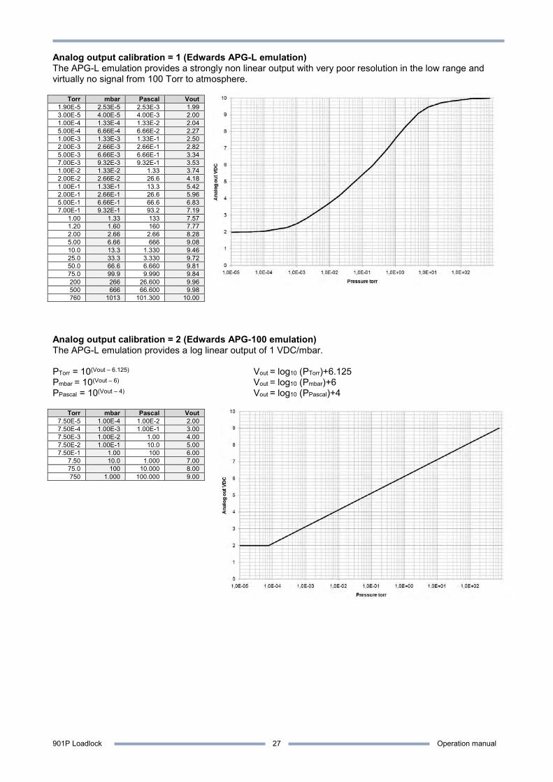
Analog output calibration = 1 (Edwards APG-L emulation) The APG-L emulation provides a strongly non linear output with very poor resolution in the low range and virtually no signal from 100 Torr to atmosphere.
Torr mbar Pascal Vout 1.90E-5 2.53E-5 2.53E-3 1.99 3.00E-5 4.00E-5 4.00E-3 2.00 1.00E-4 1.33E-4 1.33E-2 2.04 5.00E-4 6.66E-4 6.66E-2 2.27 1.00E-3 1.33E-3 1.33E-1 2.50 2.00E-3 2.66E-3 2.66E-1 2.82 5.00E-3 6.66E-3 6.66E-1 3.34 7.00E-3 9.32E-3 9.32E-1 3.53 1.00E-2 1.33E-2 1.33 3.74 2.00E-2 2.66E-2 26.6 4.18 1.00E-1 1.33E-1 13.3 5.42 2.00E-1 2.66E-1 26.6 5.96 5.00E-1 6.66E-1 66.6 6.83 7.00E-1 9.32E-1 93.2 7.19
1.00 1.33 133 7.57 1.20 1.60 160 7.77 2.00 2.66 2.66 8.28 5.00 6.66 666 9.08 10.0 13.3 1.330 9.46 25.0 33.3 3.330 9.72 50.0 66.6 6.660 9.81 75.0 99.9 9.990 9.84 200 266 26.600 9.96 500 666 66.600 9.98 760 1013 101.300 10.00
Analog output calibration = 2 (Edwards APG-100 emulation) The APG-L emulation provides a log linear output of 1 VDC/mbar. PTorr = 10(Vout – 6.125) Vout = log10 (PTorr)+6.125 Pmbar = 10(Vout – 6) Vout = log10 (Pmbar)+6 PPascal = 10(Vout – 4) Vout = log10 (PPascal)+4
Torr mbar Pascal Vout 7.50E-5 1.00E-4 1.00E-2 2.00 7.50E-4 1.00E-3 1.00E-1 3.00 7.50E-3 1.00E-2 1.00 4.00 7.50E-2 1.00E-1 10.0 5.00 7.50E-1 1.00 100 6.00
7.50 10.0 1.000 7.00 75.0 100 10.000 8.00 750 1.000 100.000 9.00
901P Loadlock Operation manual
28
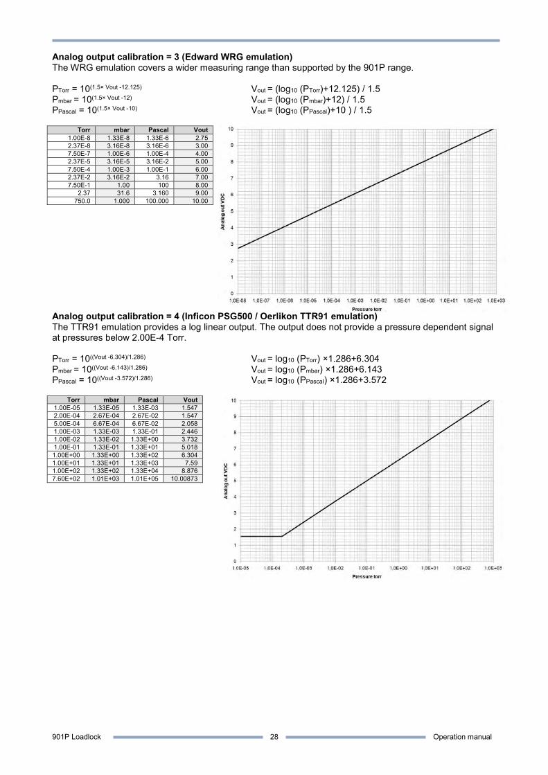
Analog output calibration = 3 (Edward WRG emulation) The WRG emulation covers a wider measuring range than supported by the 901P range. PTorr = 10(1.5× Vout -12.125) Vout = (log10 (PTorr)+12.125) / 1.5 Pmbar = 10(1.5× Vout -12) Vout = (log10 (Pmbar)+12) / 1.5 PPascal = 10(1.5× Vout -10) Vout = (log10 (PPascal)+10 ) / 1.5
Torr mbar Pascal Vout 1.00E-8 1.33E-8 1.33E-6 2.75 2.37E-8 3.16E-8 3.16E-6 3.00 7.50E-7 1.00E-6 1.00E-4 4.00 2.37E-5 3.16E-5 3.16E-2 5.00 7.50E-4 1.00E-3 1.00E-1 6.00 2.37E-2 3.16E-2 3.16 7.00 7.50E-1 1.00 100 8.00
2.37 31.6 3.160 9.00 750.0 1.000 100.000 10.00
Analog output calibration = 4 (Inficon PSG500 / Oerlikon TTR91 emulation) The TTR91 emulation provides a log linear output. The output does not provide a pressure dependent signal at pressures below 2.00E-4 Torr. PTorr = 10((Vout -6.304)/1.286) Vout = log10 (PTorr) ×1.286+6.304 Pmbar = 10((Vout -6.143)/1.286) Vout = log10 (Pmbar) ×1.286+6.143 PPascal = 10((Vout -3.572)/1.286) Vout = log10 (PPascal) ×1.286+3.572
Torr mbar Pascal Vout 1.00E-05 1.33E-05 1.33E-03 1.547 2.00E-04 2.67E-04 2.67E-02 1.547 5.00E-04 6.67E-04 6.67E-02 2.058 1.00E-03 1.33E-03 1.33E-01 2.446 1.00E-02 1.33E-02 1.33E+00 3.732 1.00E-01 1.33E-01 1.33E+01 5.018 1.00E+00 1.33E+00 1.33E+02 6.304 1.00E+01 1.33E+01 1.33E+03 7.59 1.00E+02 1.33E+02 1.33E+04 8.876 7.60E+02 1.01E+03 1.01E+05 10.00873
901P Loadlock Operation manual
29
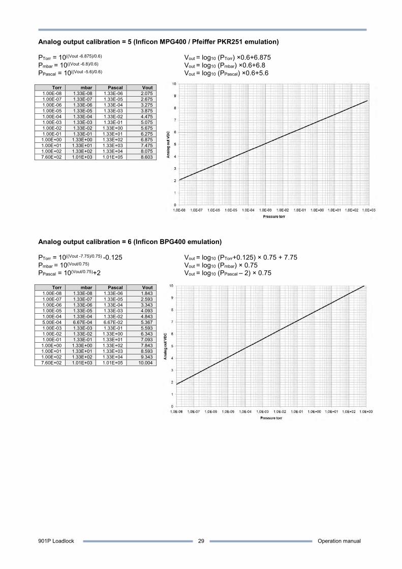
Analog output calibration = 5 (Inficon MPG400 / Pfeiffer PKR251 emulation) PTorr = 10((Vout -6.875)/0.6) Vout = log10 (PTorr) ×0.6+6.875 Pmbar = 10((Vout -6.8)/0.6) Vout = log10 (Pmbar) ×0.6+6.8 PPascal = 10((Vout -5.6)/0.6) Vout = log10 (PPascal) ×0.6+5.6
Torr mbar Pascal Vout 1.00E-08 1.33E-08 1.33E-06 2.075 1.00E-07 1.33E-07 1.33E-05 2.675 1.00E-06 1.33E-06 1.33E-04 3.275 1.00E-05 1.33E-05 1.33E-03 3.875 1.00E-04 1.33E-04 1.33E-02 4.475 1.00E-03 1.33E-03 1.33E-01 5.075 1.00E-02 1.33E-02 1.33E+00 5.675 1.00E-01 1.33E-01 1.33E+01 6.275 1.00E+00 1.33E+00 1.33E+02 6.875 1.00E+01 1.33E+01 1.33E+03 7.475 1.00E+02 1.33E+02 1.33E+04 8.075 7.60E+02 1.01E+03 1.01E+05 8.603
Analog output calibration = 6 (Inficon BPG400 emulation) PTorr = 10((Vout -7.75)/0.75) -0.125 Vout = log10 (PTorr+0.125) × 0.75 + 7.75 Pmbar = 10(Vout/0.75) Vout = log10 (Pmbar) × 0.75 PPascal = 10(Vout/0.75)+2 Vout = log10 (PPascal – 2) × 0.75
Torr mbar Pascal Vout 1.00E-08 1.33E-08 1.33E-06 1.843 1.00E-07 1.33E-07 1.33E-05 2.593 1.00E-06 1.33E-06 1.33E-04 3.343 1.00E-05 1.33E-05 1.33E-03 4.093 1.00E-04 1.33E-04 1.33E-02 4.843 5.00E-04 6.67E-04 6.67E-02 5.367 1.00E-03 1.33E-03 1.33E-01 5.593 1.00E-02 1.33E-02 1.33E+00 6.343 1.00E-01 1.33E-01 1.33E+01 7.093 1.00E+00 1.33E+00 1.33E+02 7.843 1.00E+01 1.33E+01 1.33E+03 8.593 1.00E+02 1.33E+02 1.33E+04 9.343 7.60E+02 1.01E+03 1.01E+05 10.004
901P Loadlock Operation manual
30
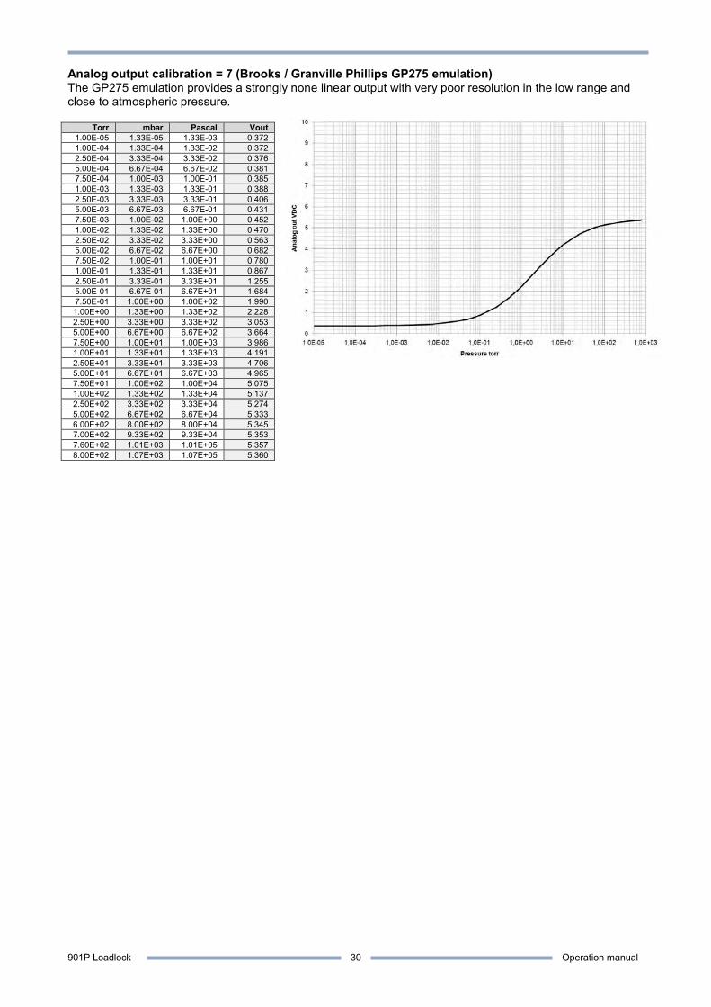
Analog output calibration = 7 (Brooks / Granville Phillips GP275 emulation) The GP275 emulation provides a strongly none linear output with very poor resolution in the low range and close to atmospheric pressure.
Torr mbar Pascal Vout 1.00E-05 1.33E-05 1.33E-03 0.372 1.00E-04 1.33E-04 1.33E-02 0.372 2.50E-04 3.33E-04 3.33E-02 0.376 5.00E-04 6.67E-04 6.67E-02 0.381 7.50E-04 1.00E-03 1.00E-01 0.385 1.00E-03 1.33E-03 1.33E-01 0.388 2.50E-03 3.33E-03 3.33E-01 0.406 5.00E-03 6.67E-03 6.67E-01 0.431 7.50E-03 1.00E-02 1.00E+00 0.452 1.00E-02 1.33E-02 1.33E+00 0.470 2.50E-02 3.33E-02 3.33E+00 0.563 5.00E-02 6.67E-02 6.67E+00 0.682 7.50E-02 1.00E-01 1.00E+01 0.780 1.00E-01 1.33E-01 1.33E+01 0.867 2.50E-01 3.33E-01 3.33E+01 1.255 5.00E-01 6.67E-01 6.67E+01 1.684 7.50E-01 1.00E+00 1.00E+02 1.990 1.00E+00 1.33E+00 1.33E+02 2.228 2.50E+00 3.33E+00 3.33E+02 3.053 5.00E+00 6.67E+00 6.67E+02 3.664 7.50E+00 1.00E+01 1.00E+03 3.986 1.00E+01 1.33E+01 1.33E+03 4.191 2.50E+01 3.33E+01 3.33E+03 4.706 5.00E+01 6.67E+01 6.67E+03 4.965 7.50E+01 1.00E+02 1.00E+04 5.075 1.00E+02 1.33E+02 1.33E+04 5.137 2.50E+02 3.33E+02 3.33E+04 5.274 5.00E+02 6.67E+02 6.67E+04 5.333 6.00E+02 8.00E+02 8.00E+04 5.345 7.00E+02 9.33E+02 9.33E+04 5.353 7.60E+02 1.01E+03 1.01E+05 5.357 8.00E+02 1.07E+03 1.07E+05 5.360
901P Loadlock Operation manual
31
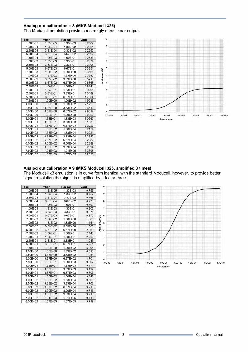
Analog out calibration = 8 (MKS Moducell 325) The Moducell emulation provides a strongly none linear output. Torr mbar Pascal Vout
1.00E-05 1.33E-05 1.33E-03 0.2509 1.00E-04 1.33E-04 1.33E-02 0.2524 2.50E-04 3.33E-04 3.33E-02 0.2550 5.00E-04 6.67E-04 6.67E-02 0.2592 7.50E-04 1.00E-03 1.00E-01 0.2633 1.00E-03 1.33E-03 1.33E-01 0.2674 2.50E-03 3.33E-03 3.33E-01 0.2905 5.00E-03 6.67E-03 6.67E-01 0.3251 7.50E-03 1.00E-02 1.00E+00 0.3561 1.00E-02 1.33E-02 1.33E+00 0.3845 2.50E-02 3.33E-02 3.33E+00 0.5215 5.00E-02 6.67E-02 6.67E+00 0.6868 7.50E-02 1.00E-01 1.00E+01 0.8144 1.00E-01 1.33E-01 1.33E+01 0.9205 2.50E-01 3.33E-01 3.33E+01 1.3489 5.00E-01 6.67E-01 6.67E+01 1.7504 7.50E-01 1.00E+00 1.00E+02 1.9986 1.00E+00 1.33E+00 1.33E+02 2.1720 2.50E+00 3.33E+00 3.33E+02 2.6512 5.00E+00 6.67E+00 6.67E+02 2.9012 7.50E+00 1.00E+01 1.00E+03 3.0022 1.00E+01 1.33E+01 1.33E+03 3.0569 2.50E+01 3.33E+01 3.33E+03 3.1639 5.00E+01 6.67E+01 6.67E+03 3.2023 7.50E+01 1.00E+02 1.00E+04 3.2154 1.00E+02 1.33E+02 1.33E+04 3.2221 2.50E+02 3.33E+02 3.33E+04 3.2342 5.00E+02 6.67E+02 6.67E+04 3.2382 6.00E+02 8.00E+02 8.00E+04 3.2389 7.00E+02 9.33E+02 9.33E+04 3.2394 7.60E+02 1.01E+03 1.01E+05 3.2396 8.00E+02 1.07E+03 1.07E+05 3.2398
Analog out calibration = 9 (MKS Moducell 325, amplified 3 times) The Moducell x3 emulation is in curve form identical with the standard Moducell, however, to provide better signal resolution the signal is amplified by a factor three. Torr mbar Pascal Vout
1.00E-05 1.33E-05 1.33E-03 0.753 1.00E-04 1.33E-04 1.33E-02 0.757 2.50E-04 3.33E-04 3.33E-02 0.765 5.00E-04 6.67E-04 6.67E-02 0.778 7.50E-04 1.00E-03 1.00E-01 0.790 1.00E-03 1.33E-03 1.33E-01 0.802 2.50E-03 3.33E-03 3.33E-01 0.871 5.00E-03 6.67E-03 6.67E-01 0.975 7.50E-03 1.00E-02 1.00E+00 1.068 1.00E-02 1.33E-02 1.33E+00 1.154 2.50E-02 3.33E-02 3.33E+00 1.565 5.00E-02 6.67E-02 6.67E+00 2.060 7.50E-02 1.00E-01 1.00E+01 2.443 1.00E-01 1.33E-01 1.33E+01 2.762 2.50E-01 3.33E-01 3.33E+01 4.047 5.00E-01 6.67E-01 6.67E+01 5.251 7.50E-01 1.00E+00 1.00E+02 5.996 1.00E+00 1.33E+00 1.33E+02 6.516 2.50E+00 3.33E+00 3.33E+02 7.954 5.00E+00 6.67E+00 6.67E+02 8.704 7.50E+00 1.00E+01 1.00E+03 9.007 1.00E+01 1.33E+01 1.33E+03 9.171 2.50E+01 3.33E+01 3.33E+03 9.492 5.00E+01 6.67E+01 6.67E+03 9.607 7.50E+01 1.00E+02 1.00E+04 9.646 1.00E+02 1.33E+02 1.33E+04 9.666 2.50E+02 3.33E+02 3.33E+04 9.702 5.00E+02 6.67E+02 6.67E+04 9.715 6.00E+02 8.00E+02 8.00E+04 9.717 7.00E+02 9.33E+02 9.33E+04 9.718 7.60E+02 1.01E+03 1.01E+05 9.719 8.00E+02 1.07E+03 1.07E+05 9.719
901P Loadlock Operation manual
32
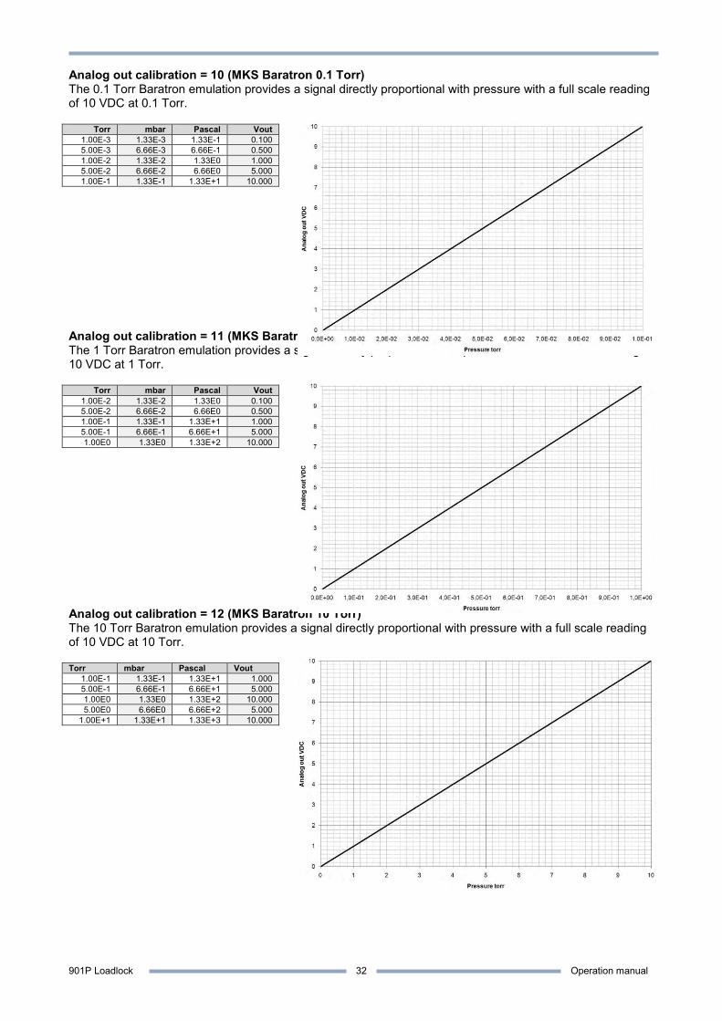
Analog out calibration = 10 (MKS Baratron 0.1 Torr) The 0.1 Torr Baratron emulation provides a signal directly proportional with pressure with a full scale reading of 10 VDC at 0.1 Torr.
Torr mbar Pascal Vout 1.00E-3 1.33E-3 1.33E-1 0.100 5.00E-3 6.66E-3 6.66E-1 0.500 1.00E-2 1.33E-2 1.33E0 1.000 5.00E-2 6.66E-2 6.66E0 5.000 1.00E-1 1.33E-1 1.33E+1 10.000
Analog out calibration = 11 (MKS Baratron 1 Torr) The 1 Torr Baratron emulation provides a signal directly proportional with pressure with a full scale reading of 10 VDC at 1 Torr.
Torr mbar Pascal Vout 1.00E-2 1.33E-2 1.33E0 0.100 5.00E-2 6.66E-2 6.66E0 0.500 1.00E-1 1.33E-1 1.33E+1 1.000 5.00E-1 6.66E-1 6.66E+1 5.000 1.00E0 1.33E0 1.33E+2 10.000
Analog out calibration = 12 (MKS Baratron 10 Torr) The 10 Torr Baratron emulation provides a signal directly proportional with pressure with a full scale reading of 10 VDC at 10 Torr. Torr mbar Pascal Vout
1.00E-1 1.33E-1 1.33E+1 1.000 5.00E-1 6.66E-1 6.66E+1 5.000 1.00E0 1.33E0 1.33E+2 10.000 5.00E0 6.66E0 6.66E+2 5.000
1.00E+1 1.33E+1 1.33E+3 10.000
901P Loadlock Operation manual
33
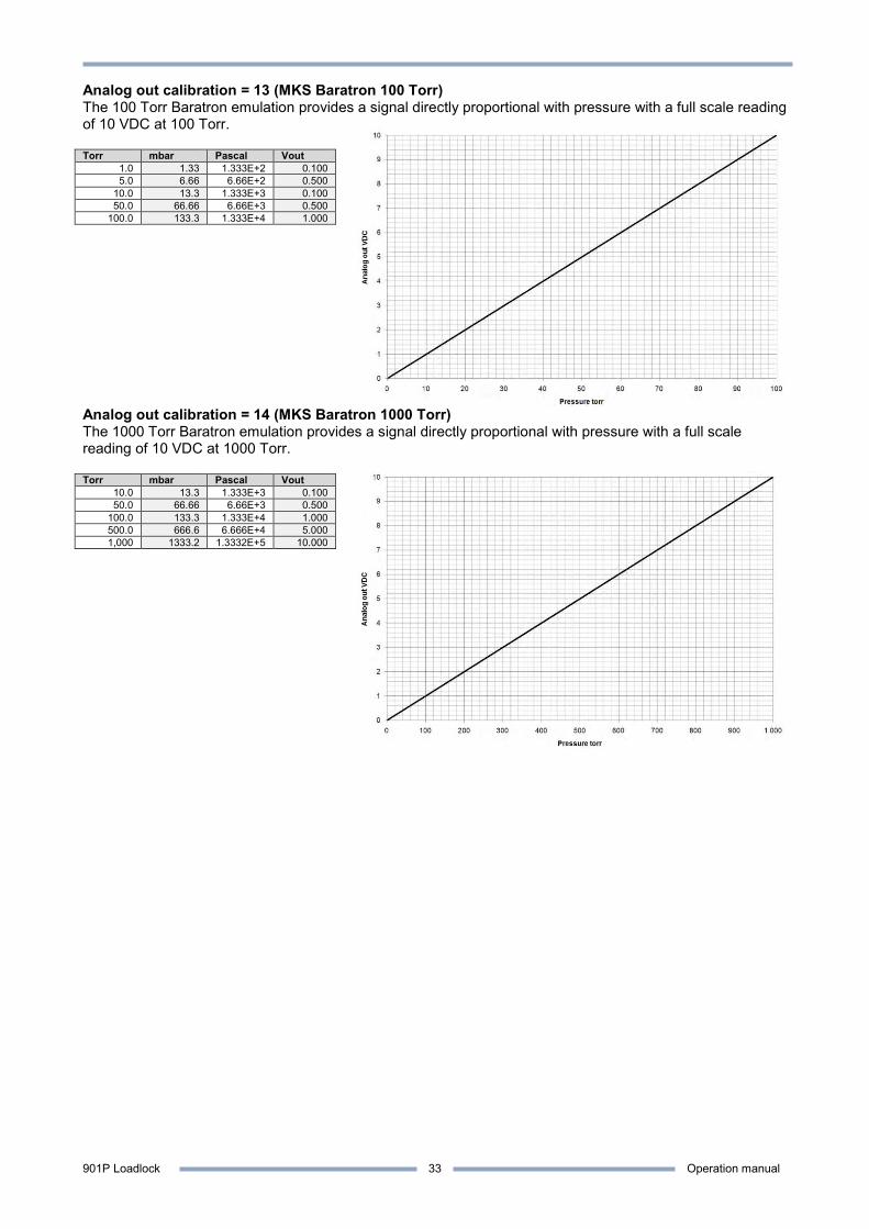
Analog out calibration = 13 (MKS Baratron 100 Torr) The 100 Torr Baratron emulation provides a signal directly proportional with pressure with a full scale reading of 10 VDC at 100 Torr. Torr mbar Pascal Vout
1.0 1.33 1.333E+2 0.100 5.0 6.66 6.66E+2 0.500
10.0 13.3 1.333E+3 0.100 50.0 66.66 6.66E+3 0.500
100.0 133.3 1.333E+4 1.000
Analog out calibration = 14 (MKS Baratron 1000 Torr) The 1000 Torr Baratron emulation provides a signal directly proportional with pressure with a full scale reading of 10 VDC at 1000 Torr. Torr mbar Pascal Vout
10.0 13.3 1.333E+3 0.100 50.0 66.66 6.66E+3 0.500
100.0 133.3 1.333E+4 1.000 500.0 666.6 6.666E+4 5.000 1,000 1333.2 1.3332E+5 10.000
901P Loadlock Operation manual
34
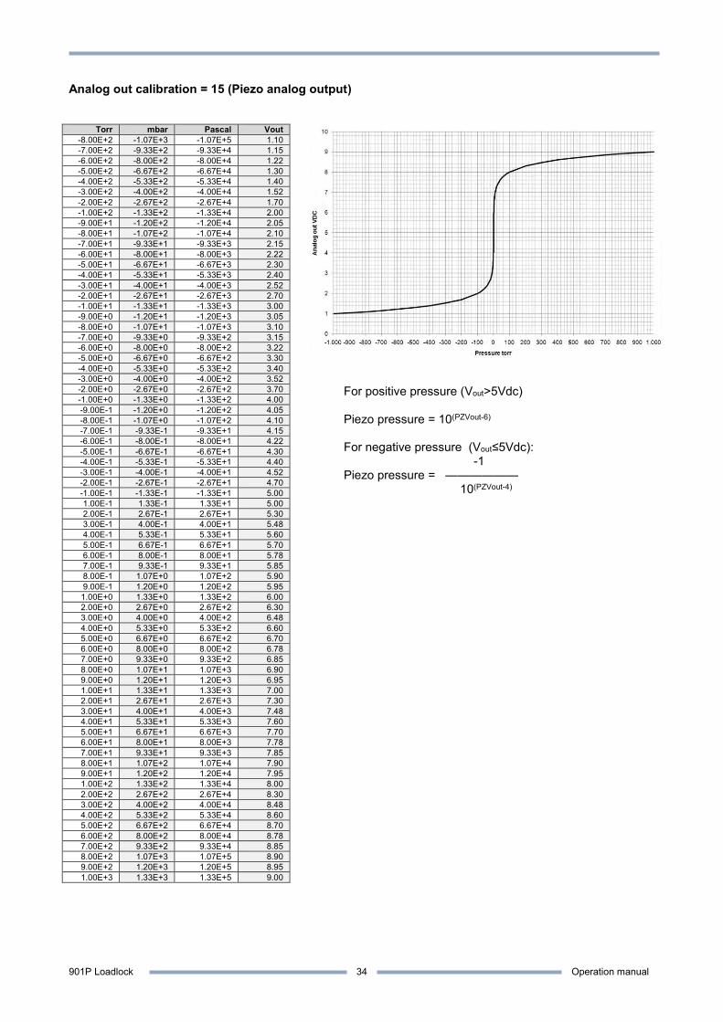
Analog out calibration = 15 (Piezo analog output)
Torr mbar Pascal Vout -8.00E+2 -1.07E+3 -1.07E+5 1.10 -7.00E+2 -9.33E+2 -9.33E+4 1.15 -6.00E+2 -8.00E+2 -8.00E+4 1.22 -5.00E+2 -6.67E+2 -6.67E+4 1.30 -4.00E+2 -5.33E+2 -5.33E+4 1.40 -3.00E+2 -4.00E+2 -4.00E+4 1.52 -2.00E+2 -2.67E+2 -2.67E+4 1.70 -1.00E+2 -1.33E+2 -1.33E+4 2.00 -9.00E+1 -1.20E+2 -1.20E+4 2.05 -8.00E+1 -1.07E+2 -1.07E+4 2.10 -7.00E+1 -9.33E+1 -9.33E+3 2.15 -6.00E+1 -8.00E+1 -8.00E+3 2.22 -5.00E+1 -6.67E+1 -6.67E+3 2.30 -4.00E+1 -5.33E+1 -5.33E+3 2.40 -3.00E+1 -4.00E+1 -4.00E+3 2.52 -2.00E+1 -2.67E+1 -2.67E+3 2.70 -1.00E+1 -1.33E+1 -1.33E+3 3.00 -9.00E+0 -1.20E+1 -1.20E+3 3.05 -8.00E+0 -1.07E+1 -1.07E+3 3.10 -7.00E+0 -9.33E+0 -9.33E+2 3.15 -6.00E+0 -8.00E+0 -8.00E+2 3.22 -5.00E+0 -6.67E+0 -6.67E+2 3.30 -4.00E+0 -5.33E+0 -5.33E+2 3.40 -3.00E+0 -4.00E+0 -4.00E+2 3.52 -2.00E+0 -2.67E+0 -2.67E+2 3.70 -1.00E+0 -1.33E+0 -1.33E+2 4.00 -9.00E-1 -1.20E+0 -1.20E+2 4.05 -8.00E-1 -1.07E+0 -1.07E+2 4.10 -7.00E-1 -9.33E-1 -9.33E+1 4.15 -6.00E-1 -8.00E-1 -8.00E+1 4.22 -5.00E-1 -6.67E-1 -6.67E+1 4.30 -4.00E-1 -5.33E-1 -5.33E+1 4.40 -3.00E-1 -4.00E-1 -4.00E+1 4.52 -2.00E-1 -2.67E-1 -2.67E+1 4.70 -1.00E-1 -1.33E-1 -1.33E+1 5.00 1.00E-1 1.33E-1 1.33E+1 5.00 2.00E-1 2.67E-1 2.67E+1 5.30 3.00E-1 4.00E-1 4.00E+1 5.48 4.00E-1 5.33E-1 5.33E+1 5.60 5.00E-1 6.67E-1 6.67E+1 5.70 6.00E-1 8.00E-1 8.00E+1 5.78 7.00E-1 9.33E-1 9.33E+1 5.85 8.00E-1 1.07E+0 1.07E+2 5.90 9.00E-1 1.20E+0 1.20E+2 5.95 1.00E+0 1.33E+0 1.33E+2 6.00 2.00E+0 2.67E+0 2.67E+2 6.30 3.00E+0 4.00E+0 4.00E+2 6.48 4.00E+0 5.33E+0 5.33E+2 6.60 5.00E+0 6.67E+0 6.67E+2 6.70 6.00E+0 8.00E+0 8.00E+2 6.78 7.00E+0 9.33E+0 9.33E+2 6.85 8.00E+0 1.07E+1 1.07E+3 6.90 9.00E+0 1.20E+1 1.20E+3 6.95 1.00E+1 1.33E+1 1.33E+3 7.00 2.00E+1 2.67E+1 2.67E+3 7.30 3.00E+1 4.00E+1 4.00E+3 7.48 4.00E+1 5.33E+1 5.33E+3 7.60 5.00E+1 6.67E+1 6.67E+3 7.70 6.00E+1 8.00E+1 8.00E+3 7.78 7.00E+1 9.33E+1 9.33E+3 7.85 8.00E+1 1.07E+2 1.07E+4 7.90 9.00E+1 1.20E+2 1.20E+4 7.95 1.00E+2 1.33E+2 1.33E+4 8.00 2.00E+2 2.67E+2 2.67E+4 8.30 3.00E+2 4.00E+2 4.00E+4 8.48 4.00E+2 5.33E+2 5.33E+4 8.60 5.00E+2 6.67E+2 6.67E+4 8.70 6.00E+2 8.00E+2 8.00E+4 8.78 7.00E+2 9.33E+2 9.33E+4 8.85 8.00E+2 1.07E+3 1.07E+5 8.90 9.00E+2 1.20E+3 1.20E+5 8.95 1.00E+3 1.33E+3 1.33E+5 9.00
For positive pressure (Vout>5Vdc) Piezo pressure = 10(PZVout-6) For negative pressure (Vout≤5Vdc): -1 Piezo pressure = ——————
10(PZVout-4)
901P Loadlock Operation manual
35
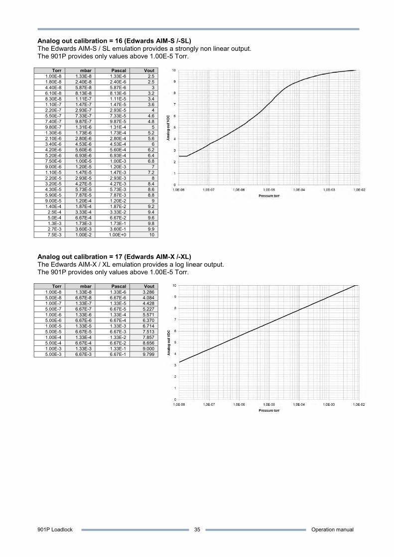
Analog out calibration = 16 (Edwards AIM-S /-SL) The Edwards AIM-S / SL emulation provides a strongly non linear output. The 901P provides only values above 1.00E-5 Torr.
Torr mbar Pascal Vout 1.00E-8 1.33E-8 1.33E-6 2.5 1.80E-8 2.40E-8 2.40E-6 2.5 4.40E-8 5.87E-8 5.87E-6 3 6.10E-8 8.13E-8 8.13E-6 3.2 8.30E-8 1.11E-7 1.11E-5 3.4 1.10E-7 1.47E-7 1.47E-5 3.6 2.20E-7 2.93E-7 2.93E-5 4 5.50E-7 7.33E-7 7.33E-5 4.6 7.40E-7 9.87E-7 9.87E-5 4.8 9.80E-7 1.31E-6 1.31E-4 5 1.30E-6 1.73E-6 1.73E-4 5.2 2.10E-6 2.80E-6 2.80E-4 5.6 3.40E-6 4.53E-6 4.53E-4 6 4.20E-6 5.60E-6 5.60E-4 6.2 5.20E-6 6.93E-6 6.93E-4 6.4 7.50E-6 1.00E-5 1.00E-3 6.8 9.00E-6 1.20E-5 1.20E-3 7 1.10E-5 1.47E-5 1.47E-3 7.2 2.20E-5 2.93E-5 2.93E-3 8 3.20E-5 4.27E-5 4.27E-3 8.4 4.30E-5 5.73E-5 5.73E-3 8.6 5.90E-5 7.87E-5 7.87E-3 8.8 9.00E-5 1.20E-4 1.20E-2 9 1.40E-4 1.87E-4 1.87E-2 9.2 2.5E-4 3.33E-4 3.33E-2 9.4 5.0E-4 6.67E-4 6.67E-2 9.6 1.3E-3 1.73E-3 1.73E-1 9.8 2.7E-3 3.60E-3 3.60E-1 9.9 7.5E-3 1.00E-2 1.00E+0 10
Analog out calibration = 17 (Edwards AIM-X /-XL) The Edwards AIM-X / XL emulation provides a log linear output. The 901P provides only values above 1.00E-5 Torr.
Torr mbar Pascal Vout 1.00E-8 1.33E-8 1.33E-6 3.286 5.00E-8 6.67E-8 6.67E-6 4.084 1.00E-7 1.33E-7 1.33E-5 4.428 5.00E-7 6.67E-7 6.67E-5 5.227 1.00E-6 1.33E-6 1.33E-4 5.571 5.00E-6 6.67E-6 6.67E-4 6.370 1.00E-5 1.33E-5 1.33E-3 6.714 5.00E-5 6.67E-5 6.67E-3 7.513 1.00E-4 1.33E-4 1.33E-2 7.857 5.00E-4 6.67E-4 6.67E-2 8.656 1.00E-3 1.33E-3 1.33E-1 9.000 5.00E-3 6.67E-3 6.67E-1 9.799
901P Loadlock Operation manual
36
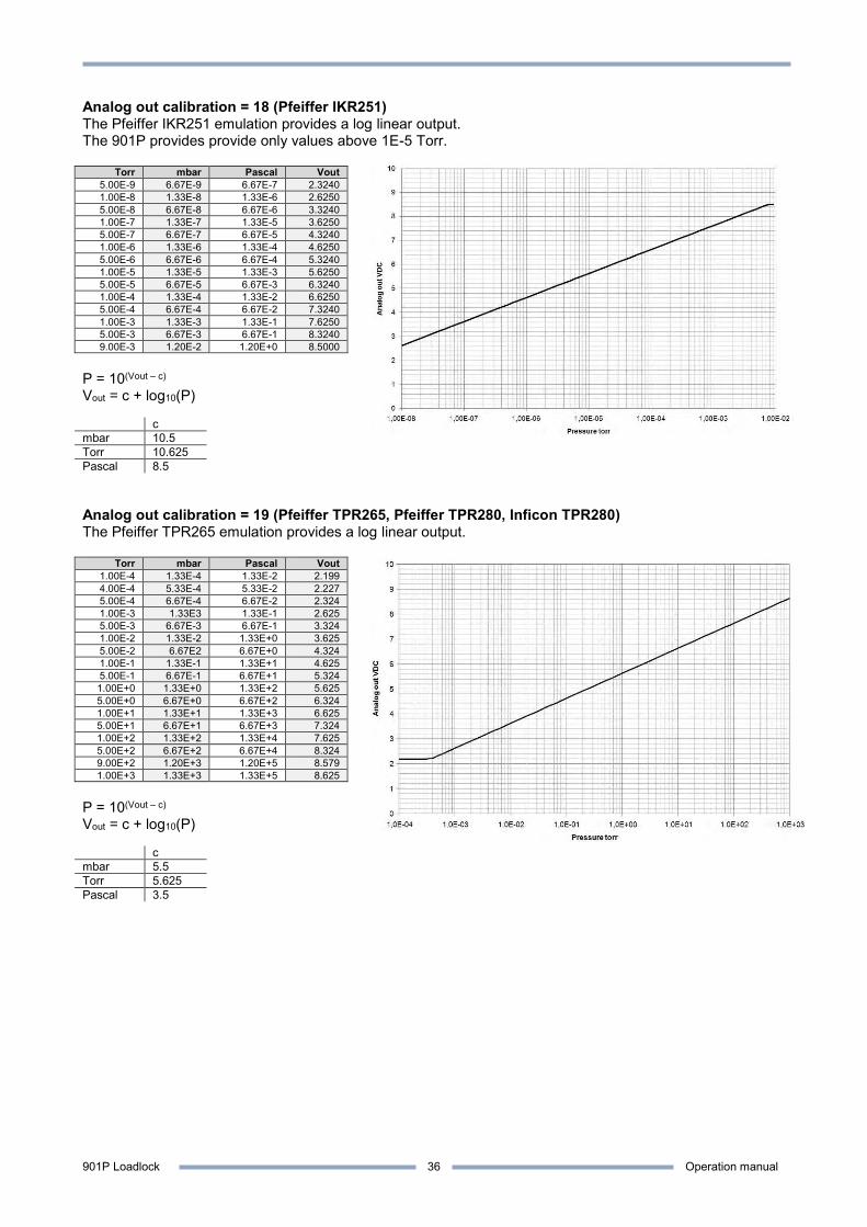
Analog out calibration = 18 (Pfeiffer IKR251) The Pfeiffer IKR251 emulation provides a log linear output. The 901P provides provide only values above 1E-5 Torr.
Torr mbar Pascal Vout 5.00E-9 6.67E-9 6.67E-7 2.3240 1.00E-8 1.33E-8 1.33E-6 2.6250 5.00E-8 6.67E-8 6.67E-6 3.3240 1.00E-7 1.33E-7 1.33E-5 3.6250 5.00E-7 6.67E-7 6.67E-5 4.3240 1.00E-6 1.33E-6 1.33E-4 4.6250 5.00E-6 6.67E-6 6.67E-4 5.3240 1.00E-5 1.33E-5 1.33E-3 5.6250 5.00E-5 6.67E-5 6.67E-3 6.3240 1.00E-4 1.33E-4 1.33E-2 6.6250 5.00E-4 6.67E-4 6.67E-2 7.3240 1.00E-3 1.33E-3 1.33E-1 7.6250 5.00E-3 6.67E-3 6.67E-1 8.3240 9.00E-3 1.20E-2 1.20E+0 8.5000
P = 10(Vout – c) Vout = c + log10(P) c mbar 10.5 Torr 10.625 Pascal 8.5 Analog out calibration = 19 (Pfeiffer TPR265, Pfeiffer TPR280, Inficon TPR280) The Pfeiffer TPR265 emulation provides a log linear output.
Torr mbar Pascal Vout 1.00E-4 1.33E-4 1.33E-2 2.199 4.00E-4 5.33E-4 5.33E-2 2.227 5.00E-4 6.67E-4 6.67E-2 2.324 1.00E-3 1.33E3 1.33E-1 2.625 5.00E-3 6.67E-3 6.67E-1 3.324 1.00E-2 1.33E-2 1.33E+0 3.625 5.00E-2 6.67E2 6.67E+0 4.324 1.00E-1 1.33E-1 1.33E+1 4.625 5.00E-1 6.67E-1 6.67E+1 5.324 1.00E+0 1.33E+0 1.33E+2 5.625 5.00E+0 6.67E+0 6.67E+2 6.324 1.00E+1 1.33E+1 1.33E+3 6.625 5.00E+1 6.67E+1 6.67E+3 7.324 1.00E+2 1.33E+2 1.33E+4 7.625 5.00E+2 6.67E+2 6.67E+4 8.324 9.00E+2 1.20E+3 1.20E+5 8.579 1.00E+3 1.33E+3 1.33E+5 8.625
P = 10(Vout – c) Vout = c + log10(P) c mbar 5.5 Torr 5.625 Pascal 3.5
901P Loadlock Operation manual
37
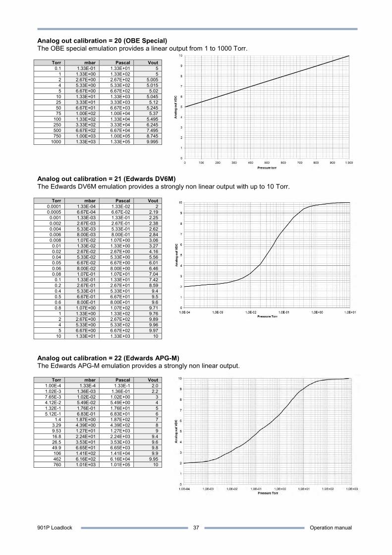
Analog out calibration = 20 (OBE Special) The OBE special emulation provides a linear output from 1 to 1000 Torr.
Torr mbar Pascal Vout 0.1 1.33E-01 1.33E+01 5
1 1.33E+00 1.33E+02 5 2 2.67E+00 2.67E+02 5.005 4 5.33E+00 5.33E+02 5.015 5 6.67E+00 6.67E+02 5.02
10 1.33E+01 1.33E+03 5.045 25 3.33E+01 3.33E+03 5.12 50 6.67E+01 6.67E+03 5.245 75 1.00E+02 1.00E+04 5.37
100 1.33E+02 1.33E+04 5.495 250 3.33E+02 3.33E+04 6.245 500 6.67E+02 6.67E+04 7.495 750 1.00E+03 1.00E+05 8.745
1000 1.33E+03 1.33E+05 9.995 Analog out calibration = 21 (Edwards DV6M) The Edwards DV6M emulation provides a strongly non linear output with up to 10 Torr.
Torr mbar Pascal Vout 0.0001 1.33E-04 1.33E-02 2 0.0005 6.67E-04 6.67E-02 2.19 0.001 1.33E-03 1.33E-01 2.25 0.002 2.67E-03 2.67E-01 2.38 0.004 5.33E-03 5.33E-01 2.62 0.006 8.00E-03 8.00E-01 2.84 0.008 1.07E-02 1.07E+00 3.06 0.01 1.33E-02 1.33E+00 3.27 0.02 2.67E-02 2.67E+00 4.16 0.04 5.33E-02 5.33E+00 5.56 0.05 6.67E-02 6.67E+00 6.01 0.06 8.00E-02 8.00E+00 6.46 0.08 1.07E-01 1.07E+01 7.04
0.1 1.33E-01 1.33E+01 7.42 0.2 2.67E-01 2.67E+01 8.59 0.4 5.33E-01 5.33E+01 9.4 0.5 6.67E-01 6.67E+01 9.5 0.6 8.00E-01 8.00E+01 9.6 0.8 1.07E+00 1.07E+02 9.71
1 1.33E+00 1.33E+02 9.76 2 2.67E+00 2.67E+02 9.89 4 5.33E+00 5.33E+02 9.96 5 6.67E+00 6.67E+02 9.97
10 1.33E+01 1.33E+03 10 Analog out calibration = 22 (Edwards APG-M) The Edwards APG-M emulation provides a strongly non linear output.
Torr mbar Pascal Vout 1.00E-4 1.33E-4 1.33E-1 2.0 1.02E-3 1.36E-03 1.36E-01 2.2
7.65E-3 1.02E-02 1.02E+00 3 4.12E-2 5.49E-02 5.49E+00 4 1.32E-1 1.76E-01 1.76E+01 5 5.12E-1 6.83E-01 6.83E+01 6
1.4 1.87E+00 1.87E+02 7 3.29 4.39E+00 4.39E+02 8 9.53 1.27E+01 1.27E+03 9 16.8 2.24E+01 2.24E+03 9.4 26.5 3.53E+01 3.53E+03 9.6 49.9 6.65E+01 6.65E+03 9.8 106 1.41E+02 1.41E+04 9.9 462 6.16E+02 6.16E+04 9.95 760 1.01E+03 1.01E+05 10
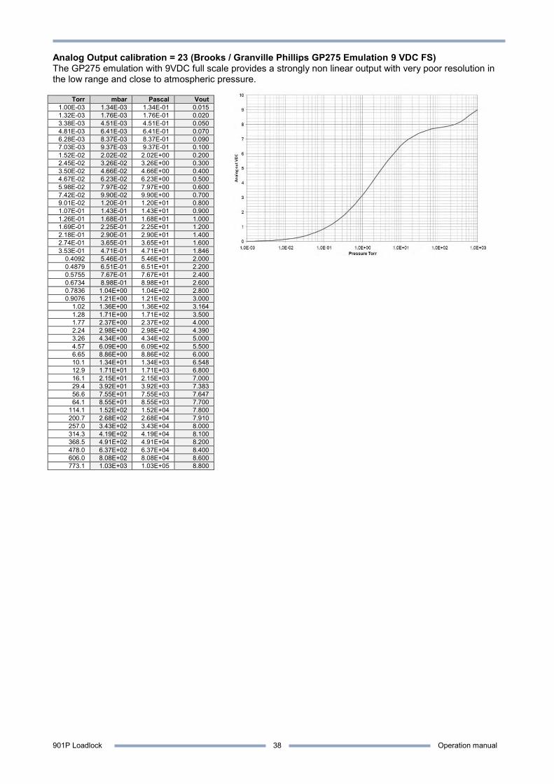
901P Loadlock Operation manual
38
Analog Output calibration = 23 (Brooks / Granville Phillips GP275 Emulation 9 VDC FS) The GP275 emulation with 9VDC full scale provides a strongly non linear output with very poor resolution in the low range and close to atmospheric pressure.
Torr mbar Pascal Vout 1.00E-03 1.34E-03 1.34E-01 0.015 1.32E-03 1.76E-03 1.76E-01 0.020 3.38E-03 4.51E-03 4.51E-01 0.050 4.81E-03 6.41E-03 6.41E-01 0.070 6.28E-03 8.37E-03 8.37E-01 0.090 7.03E-03 9.37E-03 9.37E-01 0.100 1.52E-02 2.02E-02 2.02E+00 0.200 2.45E-02 3.26E-02 3.26E+00 0.300 3.50E-02 4.66E-02 4.66E+00 0.400 4.67E-02 6.23E-02 6.23E+00 0.500 5.98E-02 7.97E-02 7.97E+00 0.600 7.42E-02 9.90E-02 9.90E+00 0.700 9.01E-02 1.20E-01 1.20E+01 0.800 1.07E-01 1.43E-01 1.43E+01 0.900 1.26E-01 1.68E-01 1.68E+01 1.000 1.69E-01 2.25E-01 2.25E+01 1.200 2.18E-01 2.90E-01 2.90E+01 1.400 2.74E-01 3.65E-01 3.65E+01 1.600 3.53E-01 4.71E-01 4.71E+01 1.846
0.4092 5.46E-01 5.46E+01 2.000 0.4879 6.51E-01 6.51E+01 2.200 0.5755 7.67E-01 7.67E+01 2.400 0.6734 8.98E-01 8.98E+01 2.600 0.7836 1.04E+00 1.04E+02 2.800 0.9076 1.21E+00 1.21E+02 3.000
1.02 1.36E+00 1.36E+02 3.164 1.28 1.71E+00 1.71E+02 3.500 1.77 2.37E+00 2.37E+02 4.000 2.24 2.98E+00 2.98E+02 4.390 3.26 4.34E+00 4.34E+02 5.000 4.57 6.09E+00 6.09E+02 5.500 6.65 8.86E+00 8.86E+02 6.000 10.1 1.34E+01 1.34E+03 6.548 12.9 1.71E+01 1.71E+03 6.800 16.1 2.15E+01 2.15E+03 7.000 29.4 3.92E+01 3.92E+03 7.383 56.6 7.55E+01 7.55E+03 7.647 64.1 8.55E+01 8.55E+03 7.700
114.1 1.52E+02 1.52E+04 7.800 200.7 2.68E+02 2.68E+04 7.910 257.0 3.43E+02 3.43E+04 8.000 314.3 4.19E+02 4.19E+04 8.100 368.5 4.91E+02 4.91E+04 8.200 478.0 6.37E+02 6.37E+04 8.400 606.0 8.08E+02 8.08E+04 8.600 773.1 1.03E+03 1.03E+05 8.800
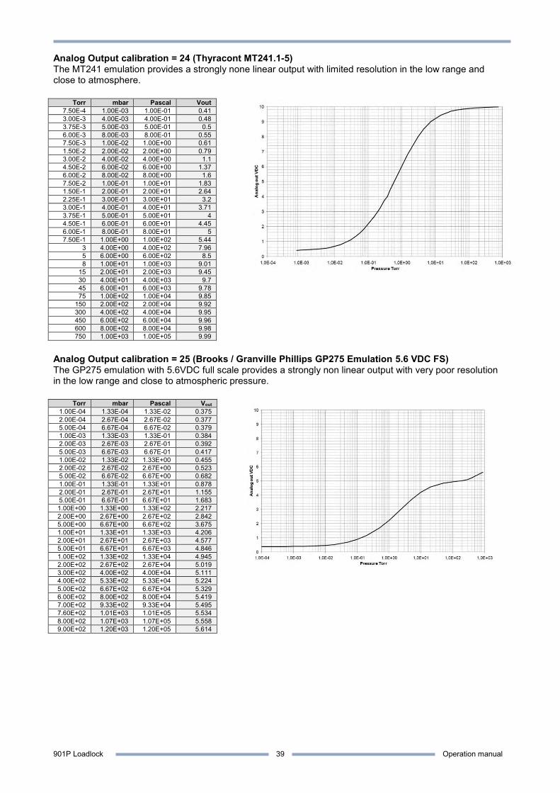
901P Loadlock Operation manual
39
Analog Output calibration = 24 (Thyracont MT241.1-5) The MT241 emulation provides a strongly none linear output with limited resolution in the low range and close to atmosphere.
Torr mbar Pascal Vout 7.50E-4 1.00E-03 1.00E-01 0.41 3.00E-3 4.00E-03 4.00E-01 0.48 3.75E-3 5.00E-03 5.00E-01 0.5 6.00E-3 8.00E-03 8.00E-01 0.55 7.50E-3 1.00E-02 1.00E+00 0.61 1.50E-2 2.00E-02 2.00E+00 0.79 3.00E-2 4.00E-02 4.00E+00 1.1 4.50E-2 6.00E-02 6.00E+00 1.37 6.00E-2 8.00E-02 8.00E+00 1.6 7.50E-2 1.00E-01 1.00E+01 1.83 1.50E-1 2.00E-01 2.00E+01 2.64 2.25E-1 3.00E-01 3.00E+01 3.2 3.00E-1 4.00E-01 4.00E+01 3.71 3.75E-1 5.00E-01 5.00E+01 4 4.50E-1 6.00E-01 6.00E+01 4.45 6.00E-1 8.00E-01 8.00E+01 5 7.50E-1 1.00E+00 1.00E+02 5.44
3 4.00E+00 4.00E+02 7.96 5 6.00E+00 6.00E+02 8.5 8 1.00E+01 1.00E+03 9.01
15 2.00E+01 2.00E+03 9.45 30 4.00E+01 4.00E+03 9.7 45 6.00E+01 6.00E+03 9.78 75 1.00E+02 1.00E+04 9.85
150 2.00E+02 2.00E+04 9.92 300 4.00E+02 4.00E+04 9.95 450 6.00E+02 6.00E+04 9.96 600 8.00E+02 8.00E+04 9.98 750 1.00E+03 1.00E+05 9.99
Analog Output calibration = 25 (Brooks / Granville Phillips GP275 Emulation 5.6 VDC FS) The GP275 emulation with 5.6VDC full scale provides a strongly non linear output with very poor resolution in the low range and close to atmospheric pressure.
Torr mbar Pascal Vout 1.00E-04 1.33E-04 1.33E-02 0.375 2.00E-04 2.67E-04 2.67E-02 0.377 5.00E-04 6.67E-04 6.67E-02 0.379 1.00E-03 1.33E-03 1.33E-01 0.384 2.00E-03 2.67E-03 2.67E-01 0.392 5.00E-03 6.67E-03 6.67E-01 0.417 1.00E-02 1.33E-02 1.33E+00 0.455 2.00E-02 2.67E-02 2.67E+00 0.523 5.00E-02 6.67E-02 6.67E+00 0.682 1.00E-01 1.33E-01 1.33E+01 0.878 2.00E-01 2.67E-01 2.67E+01 1.155 5.00E-01 6.67E-01 6.67E+01 1.683 1.00E+00 1.33E+00 1.33E+02 2.217 2.00E+00 2.67E+00 2.67E+02 2.842 5.00E+00 6.67E+00 6.67E+02 3.675 1.00E+01 1.33E+01 1.33E+03 4.206 2.00E+01 2.67E+01 2.67E+03 4.577 5.00E+01 6.67E+01 6.67E+03 4.846 1.00E+02 1.33E+02 1.33E+04 4.945 2.00E+02 2.67E+02 2.67E+04 5.019 3.00E+02 4.00E+02 4.00E+04 5.111 4.00E+02 5.33E+02 5.33E+04 5.224 5.00E+02 6.67E+02 6.67E+04 5.329 6.00E+02 8.00E+02 8.00E+04 5.419 7.00E+02 9.33E+02 9.33E+04 5.495 7.60E+02 1.01E+03 1.01E+05 5.534 8.00E+02 1.07E+03 1.07E+05 5.558 9.00E+02 1.20E+03 1.20E+05 5.614

901P Loadlock Operation manual
40
Analog Output calibration = 26 (Edwards APG100-LC) The APG100-L emulation provides a strongly none linear output with limited resolution in the low range and close to atmosphere.
Torr mbar Pascal Vout 7.50E-06 1.00E-05 1.00E-03 2 1.70E-04 2.27E-04 2.27E-02 2.1 3.75E-04 5.00E-04 5.00E-02 2.2 8.10E-04 1.08E-03 1.08E-01 2.4 1.26E-03 1.68E-03 1.68E-01 2.6 1.95E-03 2.60E-03 2.60E-01 2.8 2.88E-03 3.84E-03 3.84E-01 3 3.86E-03 5.15E-03 5.15E-01 3.2 5.15E-03 6.87E-03 6.87E-01 3.4 7.88E-03 1.05E-02 1.05E+00 3.6 1.17E-02 1.56E-02 1.56E+00 3.8 1.58E-02 2.10E-02 2.10E+00 4 2.08E-02 2.77E-02 2.77E+00 4.2 2.59E-02 3.45E-02 3.45E+00 4.4 3.12E-02 4.16E-02 4.16E+00 4.6 3.78E-02 5.04E-02 5.04E+00 4.8 4.44E-02 5.92E-02 5.92E+00 5 6.56E-02 8.74E-02 8.74E+00 5.2 9.53E-02 1.27E-01 1.27E+01 5.4 1.28E-01 1.71E-01 1.71E+01 5.6 1.67E-01 2.23E-01 2.23E+01 5.8 2.18E-01 2.90E-01 2.90E+01 6 2.68E-01 3.57E-01 3.57E+01 6.2 3.26E-01 4.35E-01 4.35E+01 6.4 4.00E-01 5.33E-01 5.33E+01 6.6 4.80E-01 6.40E-01 6.40E+01 6.8 5.75E-01 7.67E-01 7.67E+01 7 6.92E-01 9.23E-01 9.23E+01 7.2 8.55E-01 1.14E+00 1.14E+02 7.4 1.05E+00 1.40E+00 1.40E+02 7.6 1.25E+00 1.66E+00 1.66E+02 7.8 1.44E+00 1.92E+00 1.92E+02 8 1.79E+00 2.38E+00 2.38E+02 8.2 2.21E+00 2.95E+00 2.95E+02 8.4 2.63E+00 3.51E+00 3.51E+02 8.6 3.13E+00 4.17E+00 4.17E+02 8.8 4.05E+00 5.40E+00 5.40E+02 9 5.30E+00 7.06E+00 7.06E+02 9.2 7.27E+00 9.69E+00 9.69E+02 9.4 9.68E+00 1.29E+01 1.29E+03 9.5 1.25E+01 1.66E+01 1.66E+03 9.6 1.55E+01 2.07E+01 2.07E+03 9.7 2.54E+01 3.39E+01 3.39E+03 9.8 4.74E+01 6.32E+01 6.32E+03 9.9 1.08E+02 1.44E+02 1.44E+04 9.95 7.60E+02 1.00E+03 1.00E+05 10
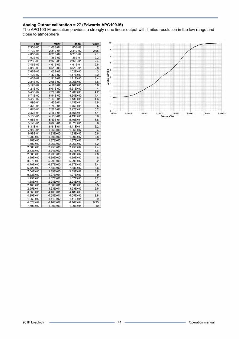
901P Loadlock Operation manual
41
Analog Output calibration = 27 (Edwards APG100-M) The APG100-M emulation provides a strongly none linear output with limited resolution in the low range and close to atmosphere
Torr mbar Pascal Vout 7.50E-05 1.00E-04 1.00E-02 2 1.73E-04 2.31E-04 2.31E-02 2.05 4.66E-04 6.21E-04 6.21E-02 2.1 1.02E-03 1.36E-03 1.36E-01 2.2 2.23E-03 2.97E-03 2.97E-01 2.4 3.46E-03 4.61E-03 4.61E-01 2.6 4.88E-03 6.51E-03 6.51E-01 2.8 7.65E-03 1.02E-02 1.02E+00 3 1.10E-02 1.47E-02 1.47E+00 3.2 1.43E-02 1.91E-02 1.91E+00 3.4 2.21E-02 2.95E-02 2.95E+00 3.6 3.12E-02 4.16E-02 4.16E+00 3.8 4.21E-02 5.61E-02 5.61E+00 4 5.40E-02 7.20E-02 7.20E+00 4.2 6.71E-02 8.94E-02 8.94E+00 4.4 8.48E-02 1.13E-01 1.13E+01 4.6 1.09E-01 1.45E-01 1.45E+01 4.8 1.32E-01 1.76E-01 1.76E+01 5 1.67E-01 2.22E-01 2.22E+01 5.2 2.37E-01 3.16E-01 3.16E+01 5.4 3.10E-01 4.13E-01 4.13E+01 5.6 4.05E-01 5.40E-01 5.40E+01 5.8 5.12E-01 6.82E-01 6.82E+01 6 6.31E-01 8.41E-01 8.41E+01 6.2 7.95E-01 1.06E+00 1.06E+02 6.4 9.98E-01 1.33E+00 1.33E+02 6.6 1.20E+00 1.60E+00 1.60E+02 6.8 1.40E+00 1.87E+00 1.87E+02 7 1.70E+00 2.26E+00 2.26E+02 7.2 2.06E+00 2.75E+00 2.75E+02 7.4 2.43E+00 3.24E+00 3.24E+02 7.6 2.80E+00 3.73E+00 3.73E+02 7.8 3.29E+00 4.39E+00 4.39E+02 8 3.97E+00 5.29E+00 5.29E+02 8.2 4.70E+00 6.27E+00 6.27E+02 8.4 5.72E+00 7.63E+00 7.63E+02 8.6 7.04E+00 9.39E+00 9.39E+02 8.8 9.53E+00 1.27E+01 1.27E+03 9 1.25E+01 1.67E+01 1.67E+03 9.2 1.68E+01 2.24E+01 2.24E+03 9.4 2.16E+01 2.88E+01 2.88E+03 9.5 2.65E+01 3.53E+01 3.53E+03 9.6 3.36E+01 4.48E+01 4.48E+03 9.7 4.99E+01 6.65E+01 6.65E+03 9.8 1.06E+02 1.41E+02 1.41E+04 9.9 4.62E+02 6.16E+02 6.16E+04 9.95 7.60E+02 1.00E+03 1.00E+05 10
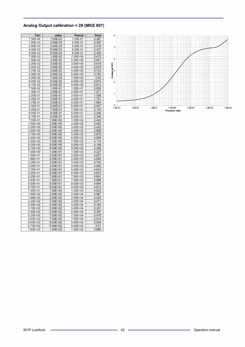
901P Loadlock Operation manual
42
Analog Output calibration = 28 (MKS 907)
Torr mbar Pascal Vout 7.50E-04 1.00E-03 1.00E-01 0.387 1.50E-03 2.00E-03 2.00E-01 0.397 3.00E-03 4.00E-03 4.00E-01 0.418 4.50E-03 6.00E-03 6.00E-01 0.437 6.00E-03 8.00E-03 8.00E-01 0.456 7.50E-03 1.00E-02 1.00E+00 0.473 1.50E-02 2.00E-02 2.00E+00 0.551 2.25E-02 3.00E-02 3.00E+00 0.619 3.00E-02 4.00E-02 4.00E+00 0.679 3.75E-02 5.00E-02 5.00E+00 0.733 4.50E-02 6.00E-02 6.00E+00 0.783 5.25E-02 7.00E-02 7.00E+00 0.83 6.00E-02 8.00E-02 8.00E+00 0.874 6.75E-02 9.00E-02 9.00E+00 0.915 7.50E-02 1.00E-01 1.00E+01 0.955 1.50E-01 2.00E-01 2.00E+01 1.271 2.25E-01 3.00E-01 3.00E+01 1.508 3.00E-01 4.00E-01 4.00E+01 1.701 3.75E-01 5.00E-01 5.00E+01 1.864 4.50E-01 6.00E-01 6.00E+01 2.007 5.25E-01 7.00E-01 7.00E+01 2.133 6.00E-01 8.00E-01 8.00E+01 2.246 6.75E-01 9.00E-01 9.00E+01 2.348 7.50E-01 1.00E+00 1.00E+02 2.442 1.50E+00 2.00E+00 2.00E+02 3.083 2.25E+00 3.00E+00 3.00E+02 3.452 3.00E+00 4.00E+00 4.00E+02 3.698 3.75E+00 5.00E+00 5.00E+02 3.875 4.50E+00 6.00E+00 6.00E+02 4.009 5.25E+00 7.00E+00 7.00E+02 4.114 6.00E+00 8.00E+00 8.00E+02 4.198 6.75E+00 9.00E+00 9.00E+02 4.268 7.50E+00 1.00E+01 1.00E+03 4.327 1.50E+01 2.00E+01 2.00E+03 4.627 1.88E+01 2.50E+01 2.50E+03 4.695 2.25E+01 3.00E+01 3.00E+03 4.743 3.00E+01 4.00E+01 4.00E+03 4.805 3.75E+01 5.00E+01 5.00E+03 4.843 4.50E+01 6.00E+01 6.00E+03 4.872 5.25E+01 7.00E+01 7.00E+03 4.891 5.63E+01 7.50E+01 7.50E+03 4.898 6.00E+01 8.00E+01 8.00E+03 4.904 6.75E+01 9.00E+01 9.00E+03 4.914 7.50E+01 1.00E+02 1.00E+04 4.923 1.50E+02 2.00E+02 2.00E+04 4.987 1.88E+02 2.50E+02 2.50E+04 5.025 2.25E+02 3.00E+02 3.00E+04 5.071 3.00E+02 4.00E+02 4.00E+04 5.183 3.75E+02 5.00E+02 5.00E+04 5.301 4.50E+02 6.00E+02 6.00E+04 5.397 5.25E+02 7.00E+02 7.00E+04 5.478 5.63E+02 7.50E+02 7.50E+04 5.514 6.00E+02 8.00E+02 8.00E+04 5.548 6.75E+02 9.00E+02 9.00E+04 5.61 7.60E+02 1.00E+03 1.00E+05 5.666
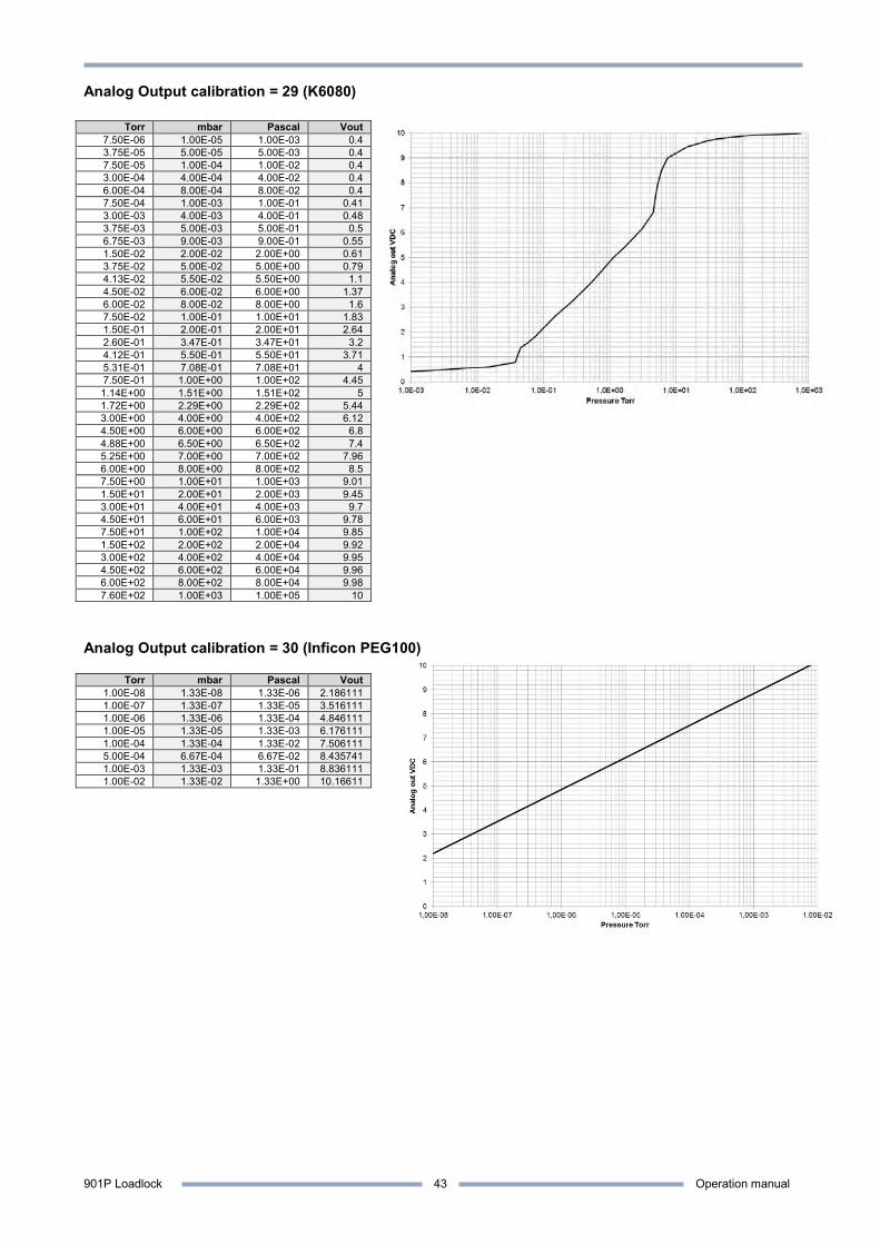
901P Loadlock Operation manual
43
Analog Output calibration = 29 (K6080)
Torr mbar Pascal Vout 7.50E-06 1.00E-05 1.00E-03 0.4 3.75E-05 5.00E-05 5.00E-03 0.4 7.50E-05 1.00E-04 1.00E-02 0.4 3.00E-04 4.00E-04 4.00E-02 0.4 6.00E-04 8.00E-04 8.00E-02 0.4 7.50E-04 1.00E-03 1.00E-01 0.41 3.00E-03 4.00E-03 4.00E-01 0.48 3.75E-03 5.00E-03 5.00E-01 0.5 6.75E-03 9.00E-03 9.00E-01 0.55 1.50E-02 2.00E-02 2.00E+00 0.61 3.75E-02 5.00E-02 5.00E+00 0.79 4.13E-02 5.50E-02 5.50E+00 1.1 4.50E-02 6.00E-02 6.00E+00 1.37 6.00E-02 8.00E-02 8.00E+00 1.6 7.50E-02 1.00E-01 1.00E+01 1.83 1.50E-01 2.00E-01 2.00E+01 2.64 2.60E-01 3.47E-01 3.47E+01 3.2 4.12E-01 5.50E-01 5.50E+01 3.71 5.31E-01 7.08E-01 7.08E+01 4 7.50E-01 1.00E+00 1.00E+02 4.45 1.14E+00 1.51E+00 1.51E+02 5 1.72E+00 2.29E+00 2.29E+02 5.44 3.00E+00 4.00E+00 4.00E+02 6.12 4.50E+00 6.00E+00 6.00E+02 6.8 4.88E+00 6.50E+00 6.50E+02 7.4 5.25E+00 7.00E+00 7.00E+02 7.96 6.00E+00 8.00E+00 8.00E+02 8.5 7.50E+00 1.00E+01 1.00E+03 9.01 1.50E+01 2.00E+01 2.00E+03 9.45 3.00E+01 4.00E+01 4.00E+03 9.7 4.50E+01 6.00E+01 6.00E+03 9.78 7.50E+01 1.00E+02 1.00E+04 9.85 1.50E+02 2.00E+02 2.00E+04 9.92 3.00E+02 4.00E+02 4.00E+04 9.95 4.50E+02 6.00E+02 6.00E+04 9.96 6.00E+02 8.00E+02 8.00E+04 9.98 7.60E+02 1.00E+03 1.00E+05 10
Analog Output calibration = 30 (Inficon PEG100)
Torr mbar Pascal Vout 1.00E-08 1.33E-08 1.33E-06 2.186111 1.00E-07 1.33E-07 1.33E-05 3.516111 1.00E-06 1.33E-06 1.33E-04 4.846111 1.00E-05 1.33E-05 1.33E-03 6.176111 1.00E-04 1.33E-04 1.33E-02 7.506111 5.00E-04 6.67E-04 6.67E-02 8.435741 1.00E-03 1.33E-03 1.33E-01 8.836111 1.00E-02 1.33E-02 1.33E+00 10.16611
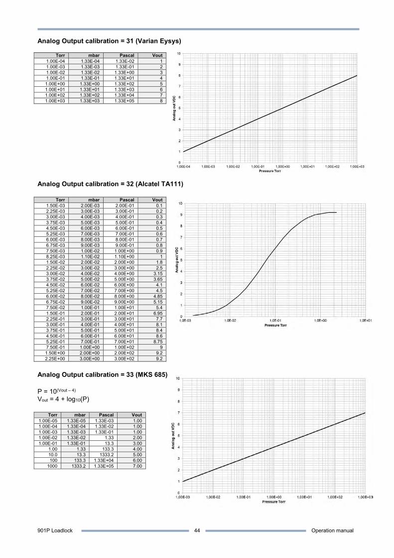
901P Loadlock Operation manual
44
Analog Output calibration = 31 (Varian Eysys)
Torr mbar Pascal Vout 1.00E-04 1.33E-04 1.33E-02 1 1.00E-03 1.33E-03 1.33E-01 2 1.00E-02 1.33E-02 1.33E+00 3 1.00E-01 1.33E-01 1.33E+01 4 1.00E+00 1.33E+00 1.33E+02 5 1.00E+01 1.33E+01 1.33E+03 6 1.00E+02 1.33E+02 1.33E+04 7 1.00E+03 1.33E+03 1.33E+05 8
Analog Output calibration = 32 (Alcatel TA111)
Torr mbar Pascal Vout 1.50E-03 2.00E-03 2.00E-01 0.1 2.25E-03 3.00E-03 3.00E-01 0.2 3.00E-03 4.00E-03 4.00E-01 0.3 3.75E-03 5.00E-03 5.00E-01 0.4 4.50E-03 6.00E-03 6.00E-01 0.5 5.25E-03 7.00E-03 7.00E-01 0.6 6.00E-03 8.00E-03 8.00E-01 0.7 6.75E-03 9.00E-03 9.00E-01 0.8 7.50E-03 1.00E-02 1.00E+00 0.9 8.25E-03 1.10E-02 1.10E+00 1 1.50E-02 2.00E-02 2.00E+00 1.8 2.25E-02 3.00E-02 3.00E+00 2.5 3.00E-02 4.00E-02 4.00E+00 3.15 3.75E-02 5.00E-02 5.00E+00 3.65 4.50E-02 6.00E-02 6.00E+00 4.1 5.25E-02 7.00E-02 7.00E+00 4.5 6.00E-02 8.00E-02 8.00E+00 4.85 6.75E-02 9.00E-02 9.00E+00 5.15 7.50E-02 1.00E-01 1.00E+01 5.4 1.50E-01 2.00E-01 2.00E+01 6.95 2.25E-01 3.00E-01 3.00E+01 7.7 3.00E-01 4.00E-01 4.00E+01 8.1 3.75E-01 5.00E-01 5.00E+01 8.4 4.50E-01 6.00E-01 6.00E+01 8.6 5.25E-01 7.00E-01 7.00E+01 8.75 7.50E-01 1.00E+00 1.00E+02 9 1.50E+00 2.00E+00 2.00E+02 9.2 2.25E+00 3.00E+00 3.00E+02 9.2
Analog Output calibration = 33 (MKS 685) P = 10(Vout – 4) Vout = 4 + log10(P)
Torr mbar Pascal Vout 1.00E-05 1.33E-05 1.33E-03 1.00 1.00E-04 1.33E-04 1.33E-02 1.00 1.00E-03 1.33E-03 1.33E-01 1.00 1.00E-02 1.33E-02 1.33 2.00 1.00E-01 1.33E-01 13.3 3.00
1.00 1.33 133.3 4.00 10.0 13.3 1333.2 5.00 100 133.3 1.33E+04 6.00
1000 1333.2 1.33E+05 7.00
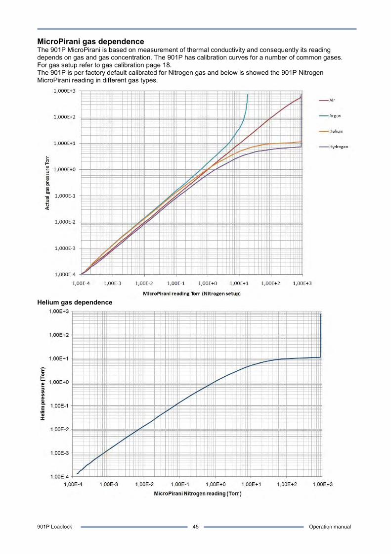
901P Loadlock Operation manual
45
MicroPirani gas dependence The 901P MicroPirani is based on measurement of thermal conductivity and consequently its reading depends on gas and gas concentration. The 901P has calibration curves for a number of common gases. For gas setup refer to gas calibration page 18. The 901P is per factory default calibrated for Nitrogen gas and below is showed the 901P Nitrogen MicroPirani reading in different gas types.
Helium gas dependence
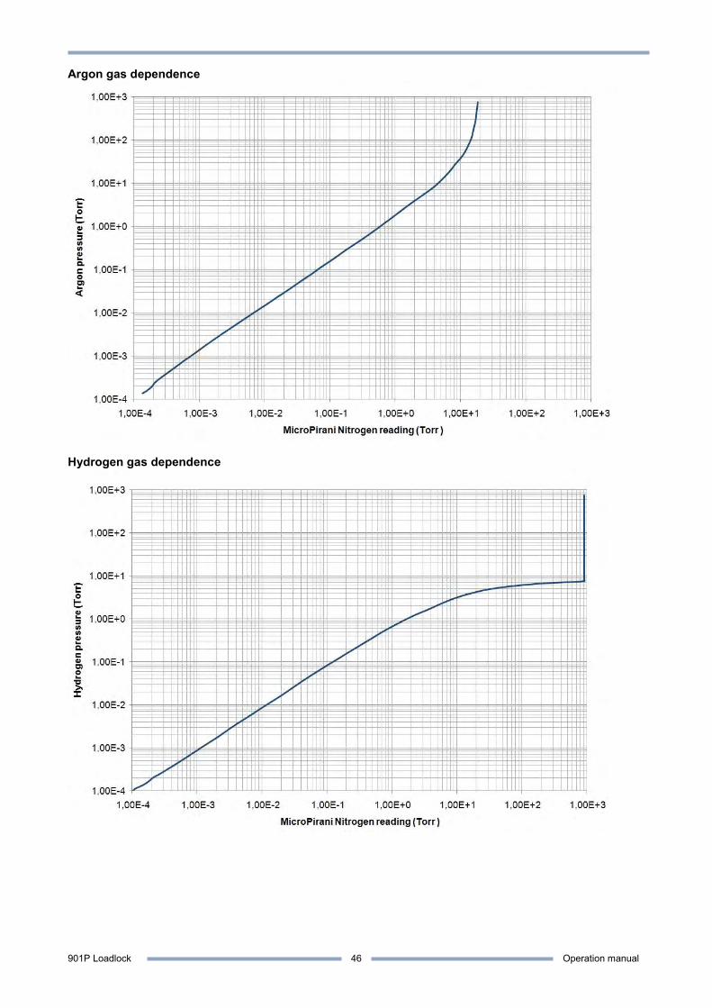
901P Loadlock Operation manual
46
Argon gas dependence
Hydrogen gas dependence
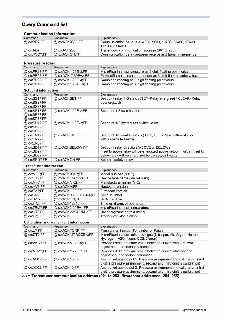
901P Loadlock Operation manual
47
Query Command list Communication information Command Response Explanation @xxxBR?;FF @xxxACK9600;FF Communication baud rate (4800, 9600, 19200, 38400, 57600,
115200,230400) @xxxAD?;FF @xxxACK253;FF Transducer communication address (001 to 253) @xxxRSD?;FF @xxxACKON;FF Communication delay between receive and transmit sequence. Pressure reading Command Response Explanation @xxxPR1?;FF @xxxACK1.23E-3;FF MicroPirani sensor pressure as 3 digit floating point value. @xxxPR2?;FF @xxxACK-7.60E+2;FF Piezo differential sensor pressure as 3 digit floating point value. @xxxPR3?;FF @xxxACK1.23E-3;FF Combined reading as 3 digit floating point value. @xxxPR4?;FF @xxxACK1.234E-3;FF Combined reading as 4 digit floating point value.
Setpoint information Command Response Explanation @xxxSS1?;FF @xxxSS2?;FF @xxxSS3?;FF
@xxxACKSET;FF Set point relay 1-3 status (SET=Relay energized / CLEAR=Relay deenergized)
@xxxSP1?;FF @xxxSP2?;FF @xxxSP3?;FF
@xxxACK1.00E-2;FF Set point 1-3 switch value.
@xxxSH1?;FF @xxxSH2?;FF @xxxSH3?;FF
@xxxACK1.10E-2;FF Set point 1-3 hystereses switch value.
@xxxEN1?;FF @xxxEN2?;FF @xxxEN3?;FF
@xxxACKDIFF;FF Set point 1-3 enable status ( OFF, DIFF=Piezo differential or ABS=Absolute Piezo)
@xxxSD1?;FF @xxxSD2?;FF @xxxSD3?;FF
@xxxACKBELOW;FF Set point relay direction (ABOVE or BELOW) If set to above relay will be energized above setpoint value. If set to below relay will be energized below setpoint value.
@xxxSPD?;FF @xxxACKON;FF Setpoint safety delay
Transducer information Command Response Explanation @xxxMD?;FF @xxxACK901P;FF Model number (901P) @xxxDT?;FF @xxxACKLoadlock;FF Device type name (MicroPirani) @xxxMF?;FF @xxxACKMKS;FF Manufacturer name (MKS) @xxxHV?;FF @xxxACKA;FF Hardware version @xxxFV?;FF @xxxACK1.00;FF Firmware version @xxxSN?;FF @xxxACK08350123456;FF Serial number @xxxSW?;FF @xxxACKON;FF Switch enable @xxxTIM?;FF @xxxACK12345;FF Time on (hours of operation ) @xxxTEM?;FF @xxxACK2.50E+1;FF MicroPirani sensor temperature @xxxUT?;FF @xxxACKVACUUM1;FF User programmed text string @xxxT?;FF @xxxACKO;FF Transducer status check
Calibration and adjustment information Command Response Explanation @xxxU?;FF @xxxACKTORR;FF Pressure unit setup (Torr, mbar or Pascal) @xxxGT?;FF @xxxACKNITROGEN;FF MicroPirani sensor calibration gas (Nitrogen, Air, Argon, Helium,
Hydrogen, H2O, Neon, CO2, Xenon) @xxxVAC?;FF @xxxACK5.12E-5;FF Provides delta pressure value between current vacuum zero
adjustment and factory calibration. @xxxATM?;FF @xxxACK1.22E+1;FF Provides delta pressure value between current atmospheric
adjustment and factory calibration. @xxxAO1?;FF @xxxACK10;FF Analog voltage output 1: Pressure assignment and calibration. (first
digit is pressure assignment, second and third digit is calibration) @xxxAO2?;FF @xxxACK10;FF Analog voltage output 2: Pressure assignment and calibration. (first
digit is pressure assignment, second and third digit is calibration) xxx = Transducer communication address (001 to 253. Broadcast addresses: 254, 255)
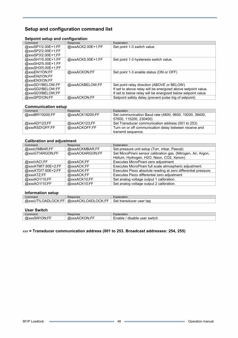
901P Loadlock Operation manual
48
Setup and configuration command list Setpoint setup and configuration Command Response Explanation @xxxSP1!2.00E+1;FF @xxxSP2!2.00E+1;FF @xxxSP3!2.00E+1;FF
@xxxACK2.00E+1;FF Set point 1-3 switch value.
@xxxSH1!5.00E+1;FF @xxxSH2!5.00E+1;FF @xxxSH3!5.00E+1;FF
@xxxACK5.00E+1;FF Set point 1-3 hysteresis switch value.
@xxxEN1!ON;FF @xxxEN2!ON;FF @xxxEN3!ON;FF
@xxxACKON;FF Set point 1-3 enable status (ON or OFF)
@xxxSD1!BELOW;FF @xxxSD2!BELOW;FF @xxxSD3!BELOW;FF
@xxxACKBELOW;FF Set point relay direction (ABOVE or BELOW) If set to above relay will be energized above setpoint value. If set to below relay will be energized below setpoint value.
@xxxSPD!ON;FF @xxxACKON;FF Setpoint safety delay (prevent pulse trig of setpoint) Communication setup Command Response Explanation @xxxBR!19200;FF @xxxACK19200;FF Set communication Baud rate (4800, 9600, 19200, 38400,
57600, 115200, 230400) @xxxAD!123;FF @xxxACK123;FF Set Transducer communication address (001 to 253) @xxxRSD!OFF;FF @xxxACKOFF;FF Turn on or off communication delay between receive and
transmit sequence. Calibration and adjustment Command Response Explanation @xxxU!MBAR;FF @xxxACKMBAR;FF Set pressure unit setup (Torr, mbar, Pascal) @xxxGT!ARGON;FF @xxxACKARGON;FF Set MicroPirani sensor calibration gas. (Nitrogen, Air, Argon,
Helium, Hydrogen, H2O, Neon, CO2, Xenon) @xxxVAC!;FF @xxxACK;FF Executes MicroPirani zero adjustment @xxxATM!7.60E+2;FF @xxxACK;FF Executes MicroPirani full scale atmospheric adjustment. @xxxATD!7.60E+2;FF @xxxACK;FF Executes Piezo absolute reading at zero differential pressure. @xxxATZ;FF @xxxACK;FF Executes Piezo differential zero adjustment @xxxAO1!10;FF @xxxACK10;FF Set analog voltage output 1 calibration. @xxxAO1!10;FF @xxxACK10;FF Set analog voltage output 2 calibration. Information setup Command Response Explanation @xxxUT!LOADLOCK;FF @xxxACKLOADLOCK;FF Set transducer user tag User Switch Command Response Explanation @xxxSW!ON;FF @xxxACKON;FF Enable / disable user switch
xxx = Transducer communication address (001 to 253. Broadcast addresses: 254, 255)
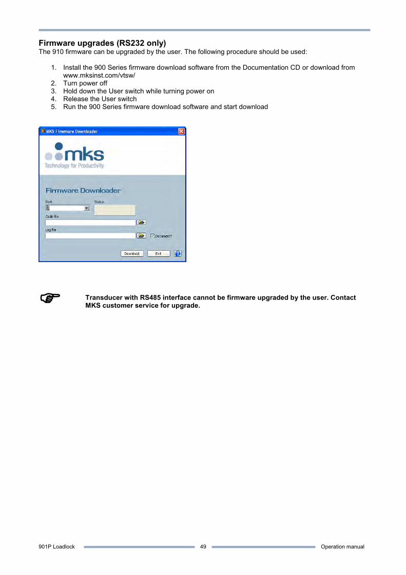
901P Loadlock Operation manual
49
Firmware upgrades (RS232 only) The 910 firmware can be upgraded by the user. The following procedure should be used:
1. Install the 900 Series firmware download software from the Documentation CD or download from www.mksinst.com/vtsw/
2. Turn power off 3. Hold down the User switch while turning power on 4. Release the User switch 5. Run the 900 Series firmware download software and start download
Transducer with RS485 interface cannot be firmware upgraded by the user. Contact MKS customer service for upgrade.

901P Loadlock Operation manual
50
FAQ (Frequently Asked Questions) Applications Q: Can the transducer and sensor element continuously withstand vibrations from a mechanical fore-pump. A: Yes – the MEMS MicroPirani sensor element can withstand continuous vibrations. Q: Is the transducer compatible with fluorine gases? A: No – the 901P is not intended for use in aggressive environments like semiconductor etch applications. Q: When the transducer is pumped down and isolated by closing a valve the pressure is raising. Is the transducer leaking? A: Not likely - when a confined space is evacuated and the pumping is stopped the pressure will rise because of out gassing, mainly by water vapor. The pressure can easily rise to a few Torr over time. Q: When the transducer is leak checked on a helium leak detector, leak reading is building up slowly after approximately 30 seconds. Is the transducer leaking? A: No - the internal sealing of the 901P transducer uses elastomer viton sealing and consequently helium molecules can permeate though the viton material and cause slow increase of helium leak readout. If a leaking transducer is tested directly on a helium leak detector the leak is almost instant displayed. Q: Can the transducer be mounted in any orientation? A: Yes - the transducer can be mounted in any orientation without compromise of performance or calibration. However it is recommended not to mount the transducer with the flange port facing upwards to avoid contamination like particulates or liquids from entering the device. Q: Can the transducer withstand instant ventilation? A: Yes - the MicroPirani and Piezo sensor elements are extremely robust to mechanical forces and can withstand continuously pressure cycles and instant air ventilation. Q: Can I connect a valve to be controlled by the transducer relay contact? A: Driving inductive loads such as valves requires special precautions. Refer to detailed description page 12. Q: How many pressure cycles can the transducer withstand? A: Both the MicroPirani and Piezo sensor element is very robust to pressure changes and there are no limits on the number of pressure cycles. The setpoint relay contact endurance is minimum 2,000,000 cycles at 30VDC/0.2A load. Analog output Q: What is the update rate of the analog output? A: 16 times per second. Q: What is the maximum length of analog output cable? A: The length of analog cable depends on cable quality and electrical noise environment, but cable length up to 100 m do not normally require any special precautions other than the cable must be screened. Q: The digital reading is correct but the analog output reading has some deviation from actual pressure? A: Check that the analog out is connected to a floating input and not an input that is connected to ground. If connected analog out return is connected to ground, the supply current will flow in the signal line and cause voltage drop and ground looping. Q: Can I get an analog output for the differential Piezo signal? A: Yes – the analog output can be configured to any of the sensor signals. Refer to analog output set up. Dual analog output is a hardware option. Refer to part numbers page 3. Digital output Q: How fast can I request pressure measurements via the digital interface? A: 10 times per second is the fastest recommended pressure request frequency. Q: How long is the waiting time from turning power on to valid measuring values? A: The power on sequence is approximately 2 seconds. The LED is illuminating red during power up sequence and the digital interface will not reply to commands.

901P Loadlock Operation manual
51
Q: The first character is sometimes lost in the transducer digital communication reply? A: This can be caused by too fast transducer communication reply. See RS delay command description page 11. Q: Is it necessary to use the ground wire between RS485 communication equipment and transducer? A: Yes - both RS232 and RS485 communication requires a 3 wire connection between transducer and communication equipment. Measurement, Calibration and adjustment Q: How often does the transducer require calibration or Zero adjustment? A: It depends on the application and pressure range but in many applications user adjustment is never required. Factors that temporally or permanently can influence the measuring performance is contamination, corrosion, heat and electronic interference. Q: How long is the warm up time before obtaining reliable measurements from the transducer? A: The small mass of the sensor element ensures short sensor warm up time. Reliable measurements are typically available within 1 minute. Q: Will the transducer retain user calibration after power is shut off? A: Yes - all transducer parameters including calibration data are stored internally in the transducer non volatile memory. Q: The 901P PR1 (MicroPirani) reads 900 Torr at atmospheric pressure of 760 Torr? A: The transducer is based on measurement of thermal conductivity and if exposed to ambient pressure the higher thermal conductivity of air will cause the transducer to read higher values. The transducer is per factory default calibrated with Nitrogen. Q: When exposed to atmospheric pressure, the combined PR3 do not change its reading with barometric pressure changes. Why? A: The PR3 absolute reading is based on the differential Piezo that measures relative to atmosphere. The output is automatically calibrated whenever the transducer is evacuated to pressure below 1.2 Torr absolute. If the transducer is not evacuated to pressure below 1.2 Torr, the absolute reading at atmospheric pressure will not change with barometric pressure changes. Q: Can the 901P provide an atmospheric switch function independent of barometric pressure changes? A: Yes, the differential Piezo sensor measures relative to atmospheric barometric pressure and consequently the Piezo setpoint value will always trig at a value relative to ambient pressure. Service and repair Q: Can the sensor element be changed if contaminated? A: No - the sensor elements cannot be changed with change without its measuring electronics. The transducer flange assembly can be exchanged with the 901P repair kit. Refer to Service and Repair page 53. Q: +24 VDC supply voltage has been connected to analog output+. Is the transducer damaged? A: Likely - the analog output is not protected against applying power to the output pin. Q: Reverse voltage has been connected to power supply input. Is the transducer damaged? A: Not likely – the transducer power supply circuit has reverse voltage and over voltage protection however. MKS cannot guarantee that the transducer will not be damaged. Q: The status LED is constantly illuminating red? A: The red status indicates a defect MicroPirani sensor element most likely damaged by corrosion or contamination. It can also occur if electronics malfunction. Refer to Service and Repair page 53.
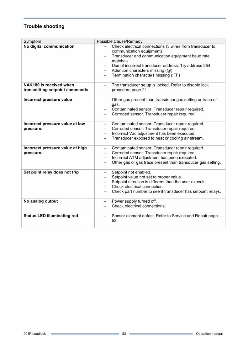
901P Loadlock Operation manual
52
Trouble shooting Symptom Possible Cause/Remedy No digital communication - Check electrical connections (3 wires from transducer to
communication equipment) - Transducer and communication equipment baud rate
matches - Use of incorrect transducer address. Try address 254 - Attention characters missing (@) - Termination characters missing (;FF)
NAK180 is received when transmitting setpoint commands
- The transducer setup is locked. Refer to disable lock procedure page 21
Incorrect pressure value - Other gas present than transducer gas setting or trace of gas.
- Contaminated sensor. Transducer repair required. - Corroded sensor. Transducer repair required.
Incorrect pressure value at low pressure.
- Contaminated sensor. Transducer repair required. - Corroded sensor. Transducer repair required. - Incorrect Vac adjustment has been executed. - Transducer exposed to heat or cooling air stream.
Incorrect pressure value at high pressure.
- Contaminated sensor. Transducer repair required. - Corroded sensor. Transducer repair required. - Incorrect ATM adjustment has been executed. - Other gas or gas trace present than transducer gas setting.
Set point relay does not trip - Setpoint not enabled.
- Setpoint value not set to proper value. - Setpoint direction is different than the user expects. - Check electrical connection. - Check part number to see if transducer has setpoint relays.
No analog output - Power supply turned off.
- Check electrical connections.
Status LED illuminating red - Sensor element defect. Refer to Service and Repair page 53.
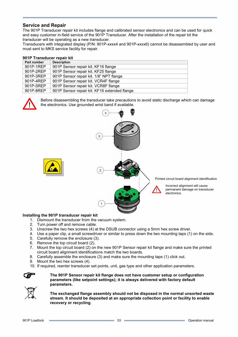
901P Loadlock Operation manual
53
Service and Repair The 901P Transducer repair kit includes flange and calibrated sensor electronics and can be used for quick and easy customer in-field service of the 901P Transducer. After the installation of the repair kit the transducer will be operating as a new transducer. Transducers with integrated display (P/N: 901P-xxxx4 and 901P-xxxx6) cannot be disassembled by user and must sent to MKS service facility for repair. 901P Transducer repair kit
Part number Description 901P-1REP 901P Sensor repair kit. KF16 flange 901P-2REP 901P Sensor repair kit. KF25 flange 901P-3REP 901P Sensor repair kit. 1/8” NPT flange 901P-4REP 901P Sensor repair kit. VCR4F flange 901P-5REP 901P Sensor repair kit. VCR8F flange 901P-8REP 901P Sensor repair kit. KF16 extended flange
Before disassembling the transducer take precautions to avoid static discharge which can damage the electronics. Use grounded wrist band if available.
Installing the 901P transducer repair kit
1. Dismount the transducer from the vacuum system. 2. Turn power off and remove cable. 3. Unscrew the two hex screws (4) at the DSUB connector using a 5mm hex screw driver. 4. Use a paper clip, a small screwdriver or similar to press down the two mounting taps (1) on the side. 5. Carefully remove the enclosure (3). 6. Remove the top circuit board (2). 7. Mount the top circuit board (2) on the new 901P Sensor repair kit flange and make sure the printed
circuit board alignment identifications match the two boards. 8. Carefully assemble the enclosure (3) and make sure the mounting taps (1) click out. 9. Mount the two hex screws (4). 10. If required, reenter transducer set points, unit, gas type and other application parameters.
The 901P Sensor repair kit flange does not have customer setup or configuration parameters (like setpoint settings); it is always delivered with factory default parameters. The exchanged flange assembly should not be disposed in the normal unsorted waste stream. It should be deposited at an appropriate collection point or facility to enable recovery or recycling.
Printed circuit board alignment identification
Incorrect alignment will cause permanent damage on transducer electronics.
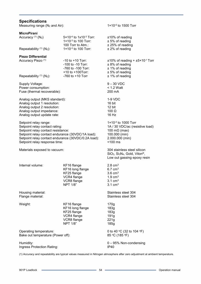
901P Loadlock Operation manual
54
Specifications Measuring range (N2 and Air): 1×10⁻⁵ to 1500 Torr MicroPirani Accuracy (1) (N2) 5×10⁻⁴ to 1x10⁻³ Torr: ±10% of reading 1×10⁻³ to 100 Torr: ± 5% of reading 100 Torr to Atm.: ± 25% of reading Repeatability (1) (N2): 1×10⁻³ to 100 Torr: ± 2% of reading Piezo Differential Accuracy Piezo (1) -10 to +10 Torr: ±10% of reading + ±5×10⁻¹ Torr -100 to -10 Torr: ± 8% of reading -760 to -100 Torr: ± 1% of reading +10 to +100Torr: ± 5% of reading Repeatability (1) (N2): -760 to +10 Torr ± 1% of reading Supply Voltage: 9 – 30 VDC Power consumption: < 1.2 Watt Fuse (thermal recoverable): 200 mA Analog output (MKS standard): 1-9 VDC Analog output 1 resolution: 16 bit Analog output 2 resolution: 12 bit Analog output impedance: 100 Ω Analog output update rate: 16 Hz Setpoint relay range: 1×10⁻⁴ to 1000 Torr Setpoint relay contact rating: 1A / 30 VDC/ac (resistive load) Setpoint relay contact resistance: 100 mΩ (max) Setpoint relay contact endurance (30VDC/1A load): 100.000 (min) Setpoint relay contact endurance (30VDC/0.2A load): 2.000.000 (min) Setpoint relay response time: <100 ms Materials exposed to vacuum: 304 stainless steel silicon SiO2, Si3N4, Gold, Viton®, Low out gassing epoxy resin Internal volume: KF16 flange 2.8 cm3 KF16 long flange 6.7 cm3 KF25 flange 3.6 cm3 VCR4 flange 1.9 cm3 VCR8 flange 3.1 cm3 NPT 1/8” 3.1 cm3 Housing material: Stainless steel 304 Flange material: Stainless steel 304 Weight: KF16 flange 170g KF16 long flange 183g KF25 flange 183g VCR4 flange 191g VCR8 flange 221g NPT 1/8” 185g Operating temperature: 0 to 40 oC (32 to 104 oF) Bake out temperature (Power off): 85 oC (185 oF) Humidity: 0 – 95% Non-condensing Ingress Protection Rating: IP40 (1) Accuracy and repeatability are typical values measured in Nitrogen atmosphere after zero adjustment at ambient temperature.
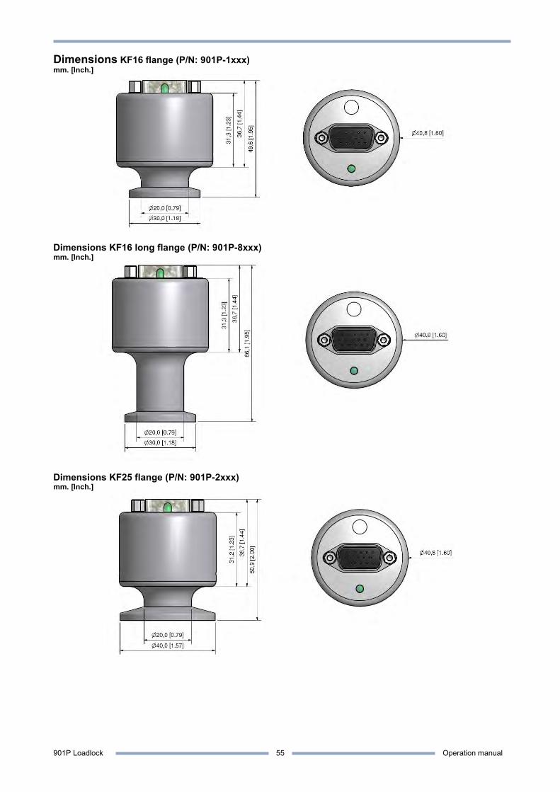
901P Loadlock Operation manual
55
Dimensions KF16 flange (P/N: 901P-1xxx) mm. [Inch.]
Dimensions KF16 long flange (P/N: 901P-8xxx) mm. [Inch.]
Dimensions KF25 flange (P/N: 901P-2xxx) mm. [Inch.]
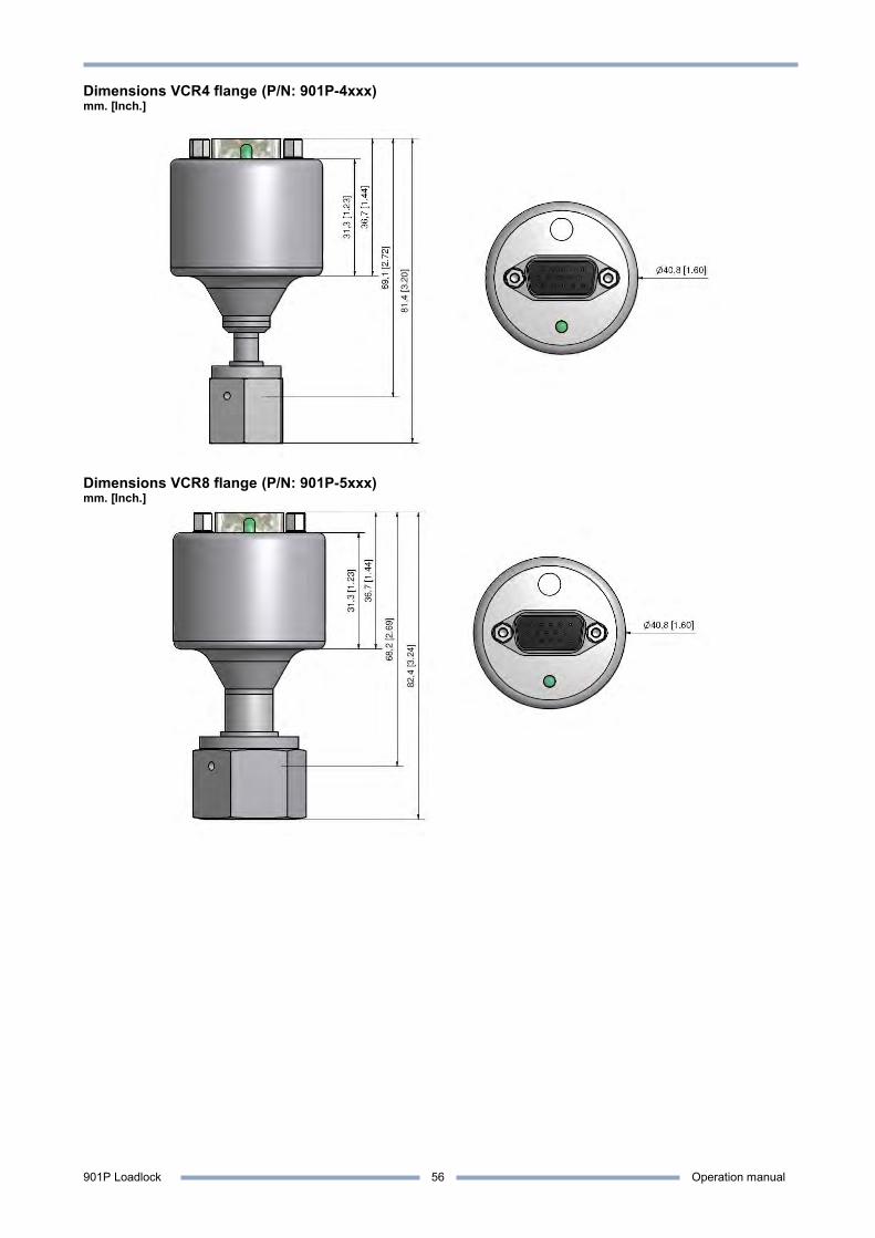
901P Loadlock Operation manual
56
Dimensions VCR4 flange (P/N: 901P-4xxx) mm. [Inch.]
Dimensions VCR8 flange (P/N: 901P-5xxx) mm. [Inch.]
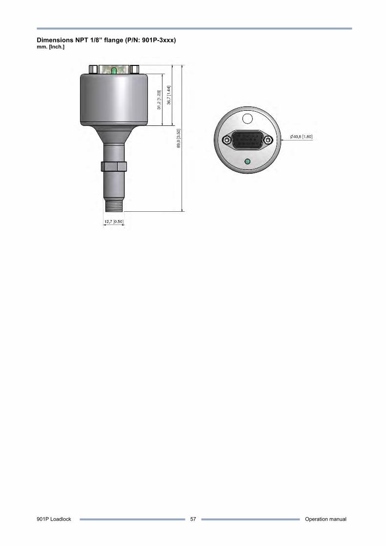
901P Loadlock Operation manual
57
Dimensions NPT 1/8” flange (P/N: 901P-3xxx) mm. [Inch.]
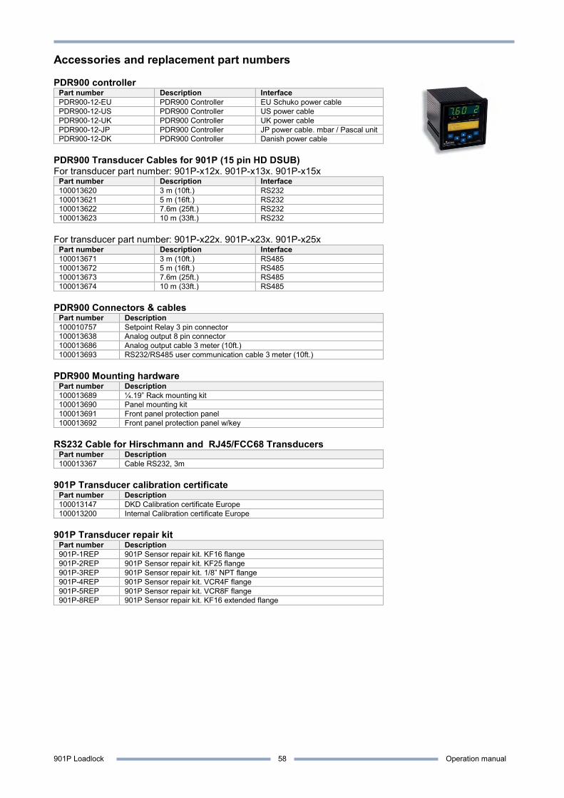
901P Loadlock Operation manual
58
Accessories and replacement part numbers PDR900 controller
Part number Description Interface PDR900-12-EU PDR900 Controller EU Schuko power cable PDR900-12-US PDR900 Controller US power cable PDR900-12-UK PDR900 Controller UK power cable PDR900-12-JP PDR900 Controller JP power cable. mbar / Pascal unit PDR900-12-DK PDR900 Controller Danish power cable
PDR900 Transducer Cables for 901P (15 pin HD DSUB) For transducer part number: 901P-x12x. 901P-x13x. 901P-x15x
Part number Description Interface 100013620 3 m (10ft.) RS232 100013621 5 m (16ft.) RS232 100013622 7.6m (25ft.) RS232 100013623 10 m (33ft.) RS232
For transducer part number: 901P-x22x. 901P-x23x. 901P-x25x
Part number Description Interface 100013671 3 m (10ft.) RS485 100013672 5 m (16ft.) RS485 100013673 7.6m (25ft.) RS485 100013674 10 m (33ft.) RS485
PDR900 Connectors & cables
Part number Description 100010757 Setpoint Relay 3 pin connector 100013638 Analog output 8 pin connector 100013686 Analog output cable 3 meter (10ft.) 100013693 RS232/RS485 user communication cable 3 meter (10ft.)
PDR900 Mounting hardware
Part number Description 100013689 ¼.19” Rack mounting kit 100013690 Panel mounting kit 100013691 Front panel protection panel 100013692 Front panel protection panel w/key
RS232 Cable for Hirschmann and RJ45/FCC68 Transducers
Part number Description 100013367 Cable RS232, 3m
901P Transducer calibration certificate
Part number Description 100013147 DKD Calibration certificate Europe 100013200 Internal Calibration certificate Europe
901P Transducer repair kit
Part number Description 901P-1REP 901P Sensor repair kit. KF16 flange 901P-2REP 901P Sensor repair kit. KF25 flange 901P-3REP 901P Sensor repair kit. 1/8” NPT flange 901P-4REP 901P Sensor repair kit. VCR4F flange 901P-5REP 901P Sensor repair kit. VCR8F flange 901P-8REP 901P Sensor repair kit. KF16 extended flange

901P Loadlock Operation manual
59
CE Declaration of Conformity Manufacturer: MKS Denmark ApS Ndr. Strandvej 119G
DK-3150 Hellebaek Denmark
Model: 901P Loadlock Type of Equipment: Vacuum pressure transducer Application of Council Directive(s): 2004/108/EEC Electromagnetic Compatibility Standard(s) to which conformity is declared: EN61326-1/2006 EMC requirements for electrical equipment for measurement. control and laboratory use. (Industrial location). Emissions EN 55022:2006 Information technology equipment. Radio disturbance characteristics. Limits and
methods of measurement Immunity EN 61000-4-2 Electrostatic discharge EN 61000-4-3 Radiated RF electromagnetic fields EN 61000-4-4 EFT/burst EN 61000-4-6 Conducted disturbances by RF fields EN 61000-4-8 Power frequency magnetic fields I, the undersigned, hereby declare that the equipment above conforms to the above Directive(s) and Standard(s). When installed in accordance with specifications specified in this short form manual and Operation and Installation manual. MKS Denmark ApS. Hellebaek. Denmark July 1, 2009 Ole Wenzel – Managing Director

901P Loadlock Operation manual
60
PDR 900 Display and power supply
Plug and play readout for 900 Series transducers The easy way for setup and configuration Data logger tool for data analysing
See more on: www.mksinst.com/pdr900
91 0 DualTrans transducer with integrated display
Display of real time pressure measurements Clear backlight display Easy viewing in all environments Readout of transducer parameters
91 0 DualTrans transducer with IP54 enclosure
Sealed enclosure for harsh environments Protected against water splash Supplied with SUB D connector and housing
900 Series VacuumLog software
Data logger software Pressure curve plotting Rate of raise diagnostic tool Pump down monitoring Export of data to Excel spread sheet Windows 7 compatible
Free version available on: http://www.mksinst.com/vtsw/

901P Loadlock Operation manual
61
Index Accessories and replacement part numbers ...... 57 Accuracy ............................................................. 53 Accuracy and repeatability.................................. 17 Addressing .......................................................... 11 Analog output ................................................ 23; 49 Applications .................................................... 4; 49 Argon gas ........................................................... 45 Atmospheric adjustment ..................................... 18 Bake out ................................................................ 6 Bake out temperature ......................................... 53 Baud rate ............................................................ 11 Calibration and adjustment ................................. 17 Calibration certificate .......................................... 57 CE Declaration of Conformity ............................. 58 CE marking ........................................................... 2 Communication delay ......................................... 11 Communication Protocol..................................... 10 Communication software .................................... 10 Contamination ....................................................... 6 Device Type ........................................................ 22 Dimensions ......................................................... 54 Display ................................................................ 14 Disposal ................................................................ 4 Dual Analog output ............................................. 25 Explosive Environments ....................................... 2 Factory default .................................................... 20 Firmware upgrade ........................................... 5; 48 Firmware Version ................................................ 22 Frequently Asked Questions .............................. 49 Fuse ................................................................ 2; 53 Gas calibration .................................................... 17 Gas dependence ................................................ 44 Grounding ............................................................. 2 Hardware Version ............................................... 22 Helium gas .......................................................... 44 Hydrogen gas ..................................................... 45 Inductive relay load ............................................. 12 Input/Output Wiring ............................................... 8 Internal volume ................................................... 53 Lock function ....................................................... 21 Manufacturer ....................................................... 22
Model ................................................................. 22 Moducell 325 ...................................................... 30 NAK Code .......................................................... 10 NAK180 .................................................. 13; 21; 51 Operating temperature ....................................... 53 Part number ......................................................... 3 Part Number ....................................................... 22 PDR900 ....................................................... 57; 59 PDR900 controller relays ................................... 12 Piezo analog output ........................................... 33 Pressure output .................................................. 15 Process compatibility ........................................... 6 Query Command list .......................................... 46 Repair ................................................................ 52 Repeatability ...................................................... 53 RS232 user interface ........................................... 9 RS485 user interface ........................................... 9 Safety information ................................................ 2 Sensor technology ............................................... 4 Serial Number .................................................... 22 Serial user interface ............................................. 9 Service and repair .................................... 2; 50; 52 Setpoint functionality .......................................... 12 Setpoint relay ..................................................... 12 Setup and configuration command list............... 47 Specifications ..................................................... 53 Supply Voltage ................................................... 53 Temperature .................................................. 6; 22 Termination resistor ............................................. 9 Time ON ............................................................. 22 Transducer installation (electrical) ....................... 7 Transducer installation (mechanical) ................... 6 Trouble shooting ................................................ 51 Unit calibration ................................................... 17 Unpacking ............................................................ 3 User Switch .................................................... 5; 21 Vacuum connections............................................ 6 Vibrations ............................................................. 6 Warranty .............................................................. 2 Zero Adjustment ................................................. 17

P/N: 100017121 901P Loadlock Transducer Operation and Installation Manual Revision: J, March 2016