Embed Size (px)
Citation preview
A subsidiary of International, Inc.
9/0.1.0Rev50309
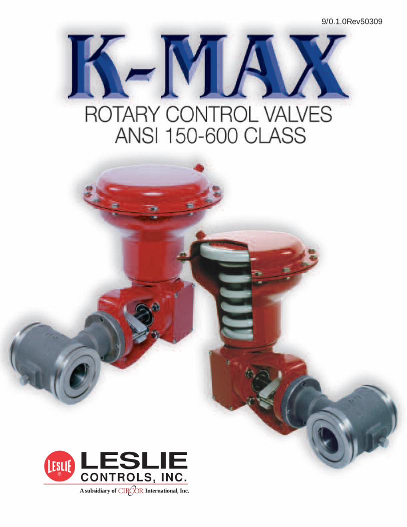
� Economical DesignThe inherent versatility of the K-Maxoffers the advantage of using one valvestyle for many applications, allowing forplant standardization and minimalstocking requirements. In addition, theefficient straight-through flow designallows for a much lower cost per C,than conventional globe style controlvalves.
� Eccentric RotaryPlug Action
The K-Max plug is offset to the shaftcenterline. This allows the plug tobreak free of the seat ring immediatelyupon initial rotation of the shaft. Sincethere is no sliding contact between theplug and the seat ring throughout trav-el, seat ring life and shutoff integrity aregreatly enhanced.
Leslie Controls’ K-MAXK-MAX Eccentric PlugRotary Control Valve was originally introduced
to the worldwide valve market by the K&M (Kieley & Mueller)Control Valve Company. The K-MAXK-MAX is a classic case of taking
a good idea and making it even better. It’s design still incorporates thecam action, low friction plug operation that provides tight shutoff over long
service life in a wide variety of flow control applications.
� Self-aligning Orbital SeatThis innovative design allows orbital movementof the seat ring to provide self-alignment withthe plug at assembly. Once seat ring to plugalignment is made, the seat is locked in placeby the seat ring retainer. The seat ring and plugrigidly mate with every closure of the valve,maintaining excellent shutoff capability.
� RangeabilityRangeability of the K-Max valve is 100:1,allowing precise throttling over a wide rangeof flows.
� Bi-directional Flow CapabilityThe normal flow direction for clean liquids,gases, and steam is flow to open (flow into theface of the plug). The recommended flow direc-tion for erosive and slurry service is flow to close(flow into the backside of the plug). Shutoffclass is maintained in either flow direction.
The K-MAXK-MAX Rotary Control Valve has improvedon the performance and durability of traditional rotary control valves
with the addition of these features:
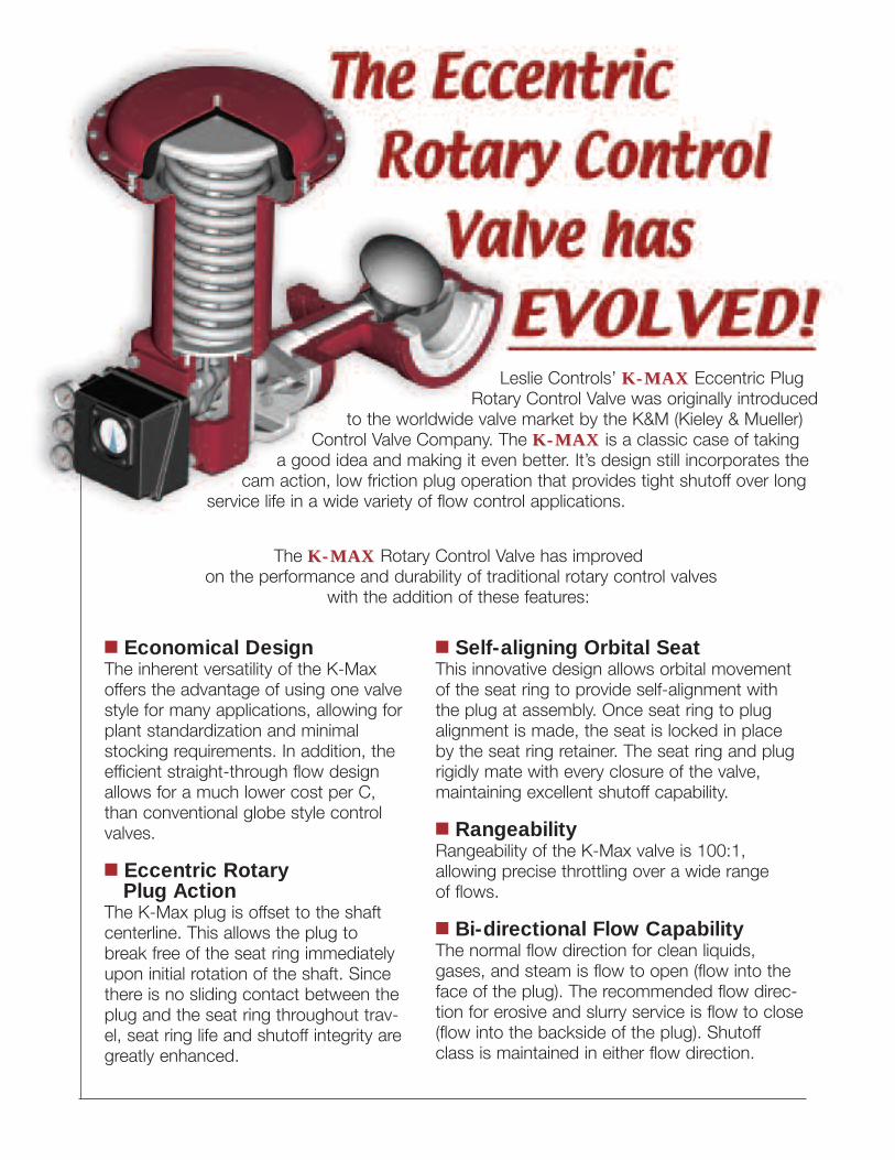
1 Dual Spline Driven Shaft
2 Large Diameter 17-4PH Stem
3 Triple Bearing Shaft Support
4 Long Packing Life andMinimized Emissions Hazardprovided by rotary valve operation.
5 Fewer Possible Leak Pathsdue to one piece, integral bonnetdesign.
6 Easy Trim Size Changesmodify valve Cv by simply replacingseat ring.
7 Customized Trim Optionsinclude Stainless Steel, Stellite®,and other alloys for a variety ofapplications such as:
� Slurry Service� Corrosive Chemicals� Erosive Conditions� Superheated Steam
8 Tight Shutoff over ExtendedService Lifeprovided by low friction, cam actionoffset plug mated with self-aligningorbital seat.
9 Easy Maintenance andClean-outassured by standard shaft accessplug.
Variety of End Connections� Wafer Style(150, 300, 600 ANSI Class)
� Separable Flanged(150, 300 ANSI Class)
� Integral Flanged(150, 300, 600 ANSI Class)
1
2
3
4
5
3
6
1
9
3
8
7
Maximum Service Life assured by these standard features:
FLOW
FLOW TO CLOSE
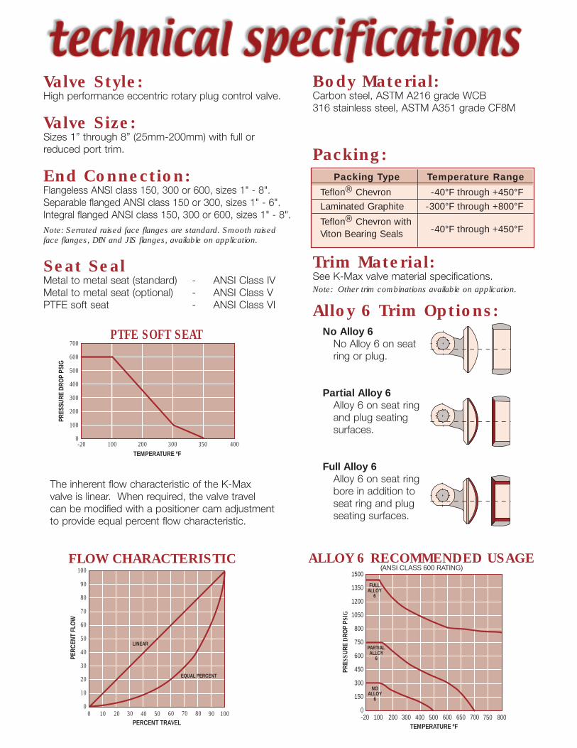
The inherent flow characteristic of the K-Maxvalve is linear. When required, the valve travelcan be modified with a positioner cam adjustmentto provide equal percent flow characteristic.
Valve Style:High performance eccentric rotary plug control valve.
Valve Size:Sizes 1” through 8” (25mm-200mm) with full orreduced port trim.
End Connection:Flangeless ANSI class 150, 300 or 600, sizes 1" - 8".Separable flanged ANSI class 150 or 300, sizes 1" - 6".Integral flanged ANSI class 150, 300 or 600, sizes 1" - 8".Note: Serrated raised face flanges are standard. Smooth raisedface flanges, DIN and JIS flanges, available on application.
Seat SealMetal to metal seat (standard) - ANSI Class IVMetal to metal seat (optional) - ANSI Class VPTFE soft seat - ANSI Class VI
Body Material:Carbon steel, ASTM A216 grade WCB316 stainless steel, ASTM A351 grade CF8M
Packing:
Trim Material:See K-Max valve material specifications.Note: Other trim combinations available on application.
Alloy 6 Trim Options:No Alloy 6No Alloy 6 on seatring or plug.
Partial Alloy 6Alloy 6 on seat ringand plug seatingsurfaces.
Full Alloy 6Alloy 6 on seat ringbore in addition toseat ring and plugseating surfaces.
Packing Type Temperature Range
Teflon® Chevron -40°F through +450°F
Laminated Graphite -300°F through +800°F
Teflon® Chevron with-40°F through +450°FViton Bearing Seals
FULLALLOY
6
PARTIALALLOY
6
NOALLOY
6
1500
1350
1200
1050
800
750
600
450
300
150
0-20 100
TEMPERATURE ºF200 300 400 500 600 650 700 800750
PRES
SURE
DRO
PPS
IG
ALLOY 6 RECOMMENDED USAGE(ANSI CLASS 600 RATING)
LINEAR
EQUAL PERCENT
100
90
80
70
60
50
40
30
20
10
00 10
PERCENT TRAVEL20 30 40 50 60 70 80 10090
PERC
ENT
FLO
W
FLOW CHARACTERISTIC
700
600
500
400
300
200
100
0
PRES
SURE
DRO
PPS
IG
PTFE SOFT SEAT
-20 100 200 300 350 400TEMPERATURE ºF
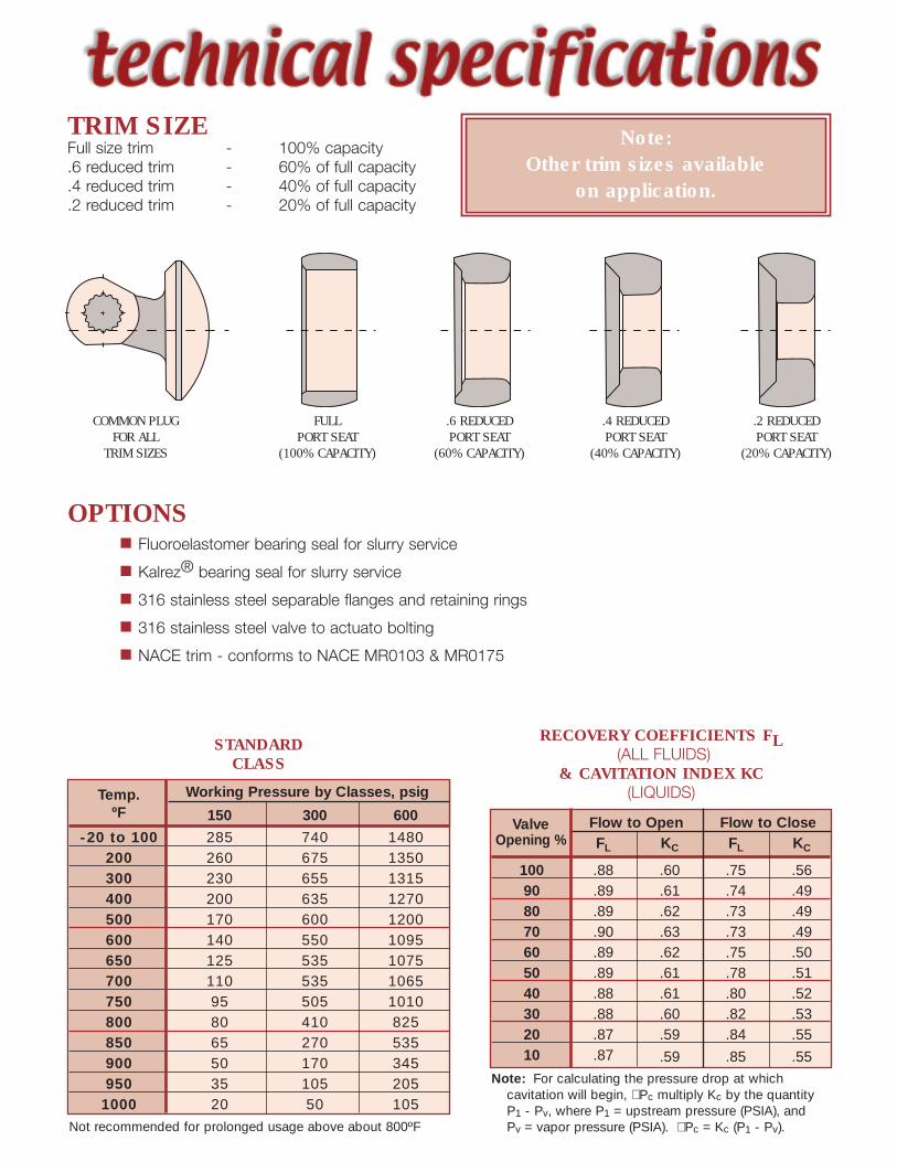
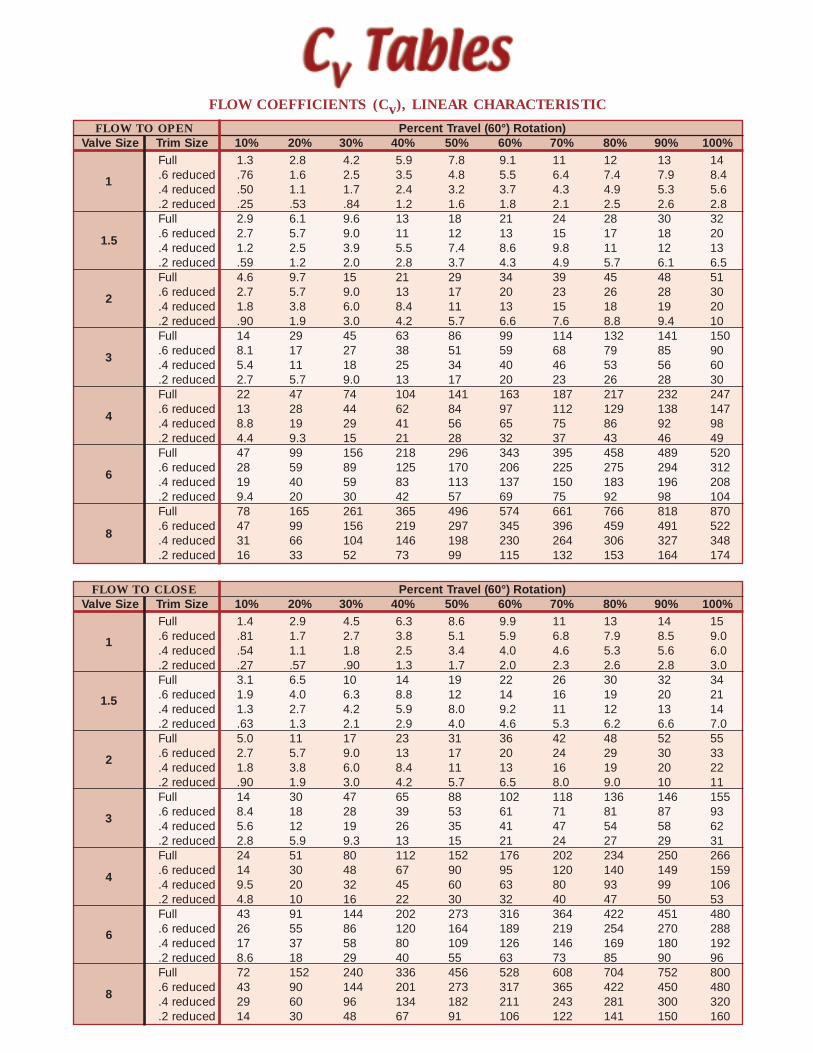
TRIM SIZEFull size trim - 100% capacity.6 reduced trim - 60% of full capacity.4 reduced trim - 40% of full capacity.2 reduced trim - 20% of full capacity
COMMON PLUGFOR ALL
TRIM SIZES
FULLPORT SEAT
(100% CAPACITY)
.6 REDUCEDPORT SEAT
(60% CAPACITY)
.4 REDUCEDPORT SEAT
(40% CAPACITY)
.2 REDUCEDPORT SEAT
(20% CAPACITY)
Valve Flow to Open Flow to CloseOpening % FL KC FL KC
100 .88 .60 .75 .5690 .89 .61 .74 .4980 .89 .62 .73 .4970 .90 .63 .73 .4960 .89 .62 .75 .5050 .89 .61 .78 .5140 .88 .61 .80 .5230 .88 .60 .82 .5320 .87 .59 .84 .5510 .87 .59 .85 .55
Temp. Working Pressure by Classes, psigºF 150 300 600
-20 to 100 285 740 1480200 260 675 1350300 230 655 1315400 200 635 1270500 170 600 1200600 140 550 1095650 125 535 1075700 110 535 1065750 95 505 1010800 80 410 825850 65 270 535900 50 170 345950 35 105 2051000 20 50 105
STANDARDCLASS
Not recommended for prolonged usage above about 800ºF
OPTIONS� Fluoroelastomer bearing seal for slurry service
� Kalrez® bearing seal for slurry service
� 316 stainless steel separable flanges and retaining rings
� 316 stainless steel valve to actuato bolting
� NACE trim - conforms to NACE MR0103 & MR0175
Note: For calculating the pressure drop at whichcavitation will begin, ∅ Pc multiply Kc by the quantityP1 - Pv, where P1 = upstream pressure (PSIA), andPv = vapor pressure (PSIA). ∅ Pc = Kc (P1 - Pv).
RECOVERY COEFFICIENTS FL(ALL FLUIDS)
& CAVITATION INDEX KC(LIQUIDS)
Note:Other trim sizes available
on application.
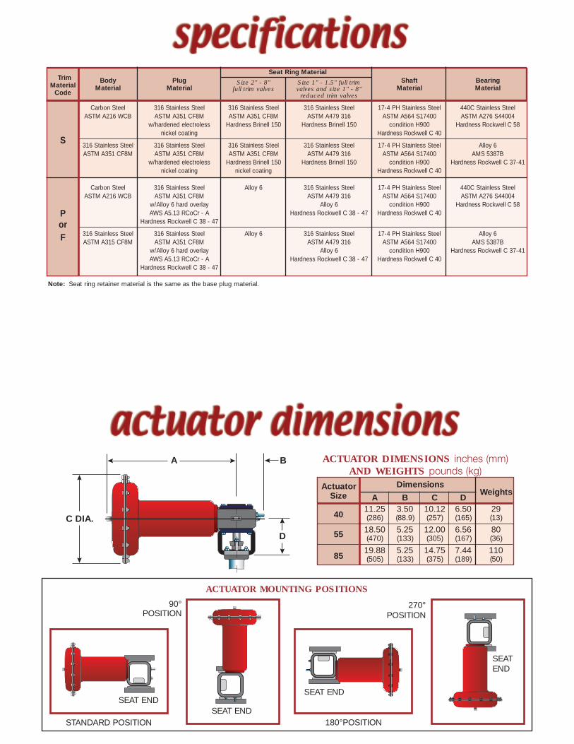
Actuator DimensionsWeightsSize A B C D
4011.25 3.50 10.12 6.50 29(286) (88.9) (257) (165) (13)
55 18.50 5.25 12.00 6.56 80(470) (133) (305) (167) (36)
8519.88 5.25 14.75 7.44 110(505) (133) (375) (189) (50)
A B
D
C DIA.
ACTUATOR MOUNTING POSITIONS
STANDARD POSITION
90°POSITION
180°POSITION
270°POSITION
Note: Seat ring retainer material is the same as the base plug material.
ACTUATOR DIMENSIONS inches (mm)AND WEIGHTS pounds (kg)
SEAT END
SEATEND
SEAT ENDSEAT END
TrimSeat Ring Material
MaterialBody Plug Size 2" - 8" Size 1" - 1.5" full trim Shaft Bearing
CodeMaterial Material full trim valves valves and size 1" - 8" Material Material
reduced trim valves
Carbon Steel 316 Stainless Steel 316 Stainless Steel 316 Stainless Steel 17-4 PH Stainless Steel 440C Stainless SteelASTM A216 WCB ASTM A351 CF8M ASTM A351 CF8M ASTM A479 316 ASTM A564 S17400 ASTM A276 S44004
w/hardened electroless Hardness Brinell 150 Hardness Brinell 150 condition H900 Hardness Rockwell C 58
Snickel coating Hardness Rockwell C 40
316 Stainless Steel 316 Stainless Steel 316 Stainless Steel 316 Stainless Steel 17-4 PH Stainless Steel Alloy 6ASTM A351 CF8M ASTM A351 CF8M ASTM A351 CF8M ASTM A479 316 ASTM A564 S17400 AMS 5387B
w/hardened electroless Hardness Brinell 150 Hardness Brinell 150 condition H900 Hardness Rockwell C 37-41nickel coating nickel coating Hardness Rockwell C 40
Carbon Steel 316 Stainless Steel Alloy 6 316 Stainless Steel 17-4 PH Stainless Steel 440C Stainless SteelASTM A216 WCB ASTM A351 CF8M ASTM A479 316 ASTM A564 S17400 ASTM A276 S44004
w/Alloy 6 hard overlay Alloy 6 condition H900 Hardness Rockwell C 58
P AWS A5.13 RCoCr - A Hardness Rockwell C 38 - 47 Hardness Rockwell C 40
or Hardness Rockwell C 38 - 47
F 316 Stainless Steel 316 Stainless Steel Alloy 6 316 Stainless Steel 17-4 PH Stainless Steel Alloy 6ASTM A315 CF8M ASTM A351 CF8M ASTM A479 316 ASTM A564 S17400 AMS 5387B
w/Alloy 6 hard overlay Alloy 6 condition H900 Hardness Rockwell C 37-41AWS A5.13 RCoCr - A Hardness Rockwell C 38 - 47 Hardness Rockwell C 40
Hardness Rockwell C 38 - 47
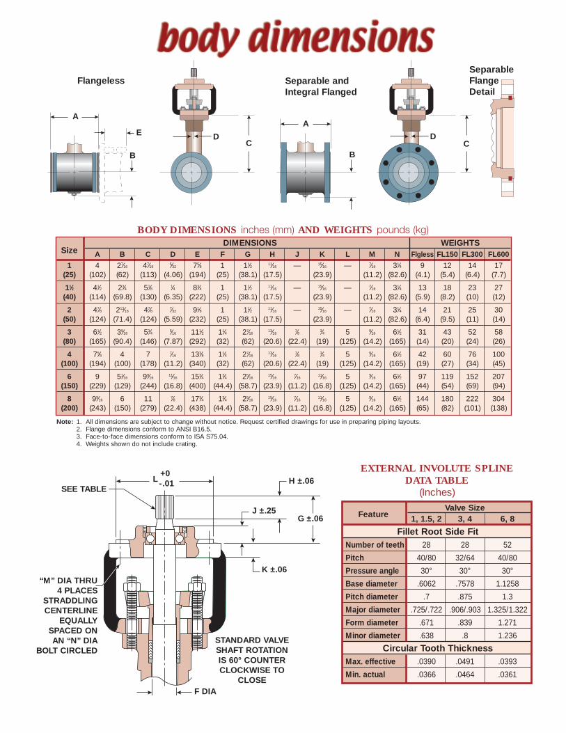
Flangeless Separable andIntegral Flanged
SeparableFlangeDetail
H ±.06
G ±.06
L+0-.01
J ±.25
K ±.06
SEE TABLE
“M” DIA THRU4 PLACES
STRADDLINGCENTERLINE
EQUALLYSPACED ONAN “N” DIA
BOLT CIRCLED
F DIA
STANDARD VALVESHAFT ROTATIONIS 60° COUNTERCLOCKWISE TO
CLOSE
FeatureValve Size
1, 1.5, 2 3, 4 6, 8
Fillet Root Side FitNumber of teeth 28 28 52
Pitch 40/80 32/64 40/80
Pressure angle 30° 30° 30°
Base diameter .6062 .7578 1.1258
Pitch diameter .7 .875 1.3
Major diameter .725/.722 .906/.903 1.325/1.322
Form diameter .671 .839 1.271
Minor diameter .638 .8 1.236
Circular Tooth ThicknessMax. effective .0390 .0491 .0393
Min. actual .0366 .0464 .0361
EXTERNAL INVOLUTE SPLINEDATA TABLE
(Inches)
DIMENSIONS WEIGHTSSize A B C D E F G H J K L M N Flgless FL150 FL300 FL600
1 4 27⁄16 47⁄16 5⁄32 75⁄8 1 11⁄2 11⁄16 — 15⁄16 — 7⁄16 31⁄4 9 12 14 17(25) (102) (62) (113) (4.06) (194) (25) (38.1) (17.5) (23.9) (11.2) (82.6) (4.1) (5.4) (6.4) (7.7)
11⁄2 41⁄2 23⁄4 51⁄8 1⁄4 83⁄4 1 11⁄2 11⁄16 — 15⁄16 — 7⁄16 31⁄4 13 18 23 27(40) (114) (69.8) (130) (6.35) (222) (25) (38.1) (17.5) (23.9) (11.2) (82.6) (5.9) (8.2) (10) (12)
2 47⁄8 213⁄16 47⁄8 7⁄32 91⁄8 1 11⁄2 11⁄16 — 15⁄16 — 7⁄16 31⁄4 14 21 25 30(50) (124) (71.4) (124) (5.59) (232) (25) (38.1) (17.5) (23.9) (11.2) (82.6) (6.4) (9.5) (11) (14)
3 61⁄2 39⁄16 53⁄4 5⁄16 111⁄2 11⁄4 27⁄16 13⁄16 7⁄8 3⁄4 5 9⁄16 61⁄2 31 43 52 58(80) (165) (90.4) (146) (7.87) (292) (32) (62) (20.6) (22.4) (19) (125) (14.2) (165) (14) (20) (24) (26)
4 75⁄8 4 7 7⁄16 133⁄8 11⁄4 27⁄16 13⁄16 7⁄8 3⁄4 5 9⁄16 61⁄2 42 60 76 100(100) (194) (100) (178) (11.2) (340) (32) (62) (20.6) (22.4) (19) (125) (14.2) (165) (19) (27) (34) (45)
6 9 51⁄16 99⁄16 11⁄16 153⁄4 13⁄4 25⁄16 15⁄16 7⁄16 11⁄16 5 9⁄16 61⁄2 97 119 152 207(150) (229) (129) (244) (16.8) (400) (44.4) (58.7) (23.9) (11.2) (16.8) (125) (14.2) (165) (44) (54) (69) (94)
8 99⁄16 6 11 7⁄8 173⁄4 13⁄4 25⁄16 15⁄16 7⁄16 11⁄16 5 9⁄16 61⁄2 144 180 222 304(200) (243) (150) (279) (22.4) (438) (44.4) (58.7) (23.9) (11.2) (16.8) (125) (14.2) (165) (65) (82) (101) (138)
Note: 1. All dimensions are subject to change without notice. Request certified drawings for use in preparing piping layouts.2. Flange dimensions conform to ANSI B16.5.3. Face-to-face dimensions conform to ISA S75.04.4. Weights shown do not include crating.
BODY DIMENSIONS inches (mm) AND WEIGHTS pounds (kg)
A
B
EC
A
BC
DD
FLOW TO OPEN Percent Travel (60°) Rotation)Valve Size Trim Size 10% 20% 30% 40% 50% 60% 70% 80% 90% 100%
Full 1.3 2.8 4.2 5.9 7.8 9.1 11 12 13 14.6 reduced .76 1.6 2.5 3.5 4.8 5.5 6.4 7.4 7.9 8.4.4 reduced .50 1.1 1.7 2.4 3.2 3.7 4.3 4.9 5.3 5.6.2 reduced .25 .53 .84 1.2 1.6 1.8 2.1 2.5 2.6 2.8Full 2.9 6.1 9.6 13 18 21 24 28 30 32.6 reduced 2.7 5.7 9.0 11 12 13 15 17 18 20.4 reduced 1.2 2.5 3.9 5.5 7.4 8.6 9.8 11 12 13.2 reduced .59 1.2 2.0 2.8 3.7 4.3 4.9 5.7 6.1 6.5Full 4.6 9.7 15 21 29 34 39 45 48 51.6 reduced 2.7 5.7 9.0 13 17 20 23 26 28 30.4 reduced 1.8 3.8 6.0 8.4 11 13 15 18 19 20.2 reduced .90 1.9 3.0 4.2 5.7 6.6 7.6 8.8 9.4 10Full 14 29 45 63 86 99 114 132 141 150.6 reduced 8.1 17 27 38 51 59 68 79 85 90.4 reduced 5.4 11 18 25 34 40 46 53 56 60.2 reduced 2.7 5.7 9.0 13 17 20 23 26 28 30Full 22 47 74 104 141 163 187 217 232 247.6 reduced 13 28 44 62 84 97 112 129 138 147.4 reduced 8.8 19 29 41 56 65 75 86 92 98.2 reduced 4.4 9.3 15 21 28 32 37 43 46 49Full 47 99 156 218 296 343 395 458 489 520.6 reduced 28 59 89 125 170 206 225 275 294 312.4 reduced 19 40 59 83 113 137 150 183 196 208.2 reduced 9.4 20 30 42 57 69 75 92 98 104Full 78 165 261 365 496 574 661 766 818 870.6 reduced 47 99 156 219 297 345 396 459 491 522.4 reduced 31 66 104 146 198 230 264 306 327 348.2 reduced 16 33 52 73 99 115 132 153 164 174
FLOW COEFFICIENTS (Cv), LINEAR CHARACTERISTIC
1
1.5
2
3
4
6
8
FLOW TO CLOSE Percent Travel (60°) Rotation)Valve Size Trim Size 10% 20% 30% 40% 50% 60% 70% 80% 90% 100%
Full 1.4 2.9 4.5 6.3 8.6 9.9 11 13 14 15.6 reduced .81 1.7 2.7 3.8 5.1 5.9 6.8 7.9 8.5 9.0.4 reduced .54 1.1 1.8 2.5 3.4 4.0 4.6 5.3 5.6 6.0.2 reduced .27 .57 .90 1.3 1.7 2.0 2.3 2.6 2.8 3.0Full 3.1 6.5 10 14 19 22 26 30 32 34.6 reduced 1.9 4.0 6.3 8.8 12 14 16 19 20 21.4 reduced 1.3 2.7 4.2 5.9 8.0 9.2 11 12 13 14.2 reduced .63 1.3 2.1 2.9 4.0 4.6 5.3 6.2 6.6 7.0Full 5.0 11 17 23 31 36 42 48 52 55.6 reduced 2.7 5.7 9.0 13 17 20 24 29 30 33.4 reduced 1.8 3.8 6.0 8.4 11 13 16 19 20 22.2 reduced .90 1.9 3.0 4.2 5.7 6.5 8.0 9.0 10 11Full 14 30 47 65 88 102 118 136 146 155.6 reduced 8.4 18 28 39 53 61 71 81 87 93.4 reduced 5.6 12 19 26 35 41 47 54 58 62.2 reduced 2.8 5.9 9.3 13 15 21 24 27 29 31Full 24 51 80 112 152 176 202 234 250 266.6 reduced 14 30 48 67 90 95 120 140 149 159.4 reduced 9.5 20 32 45 60 63 80 93 99 106.2 reduced 4.8 10 16 22 30 32 40 47 50 53Full 43 91 144 202 273 316 364 422 451 480.6 reduced 26 55 86 120 164 189 219 254 270 288.4 reduced 17 37 58 80 109 126 146 169 180 192.2 reduced 8.6 18 29 40 55 63 73 85 90 96Full 72 152 240 336 456 528 608 704 752 800.6 reduced 43 90 144 201 273 317 365 422 450 480.4 reduced 29 60 96 134 182 211 243 281 300 320.2 reduced 14 30 48 67 91 106 122 141 150 160
1
1.5
2
3
4
6
8
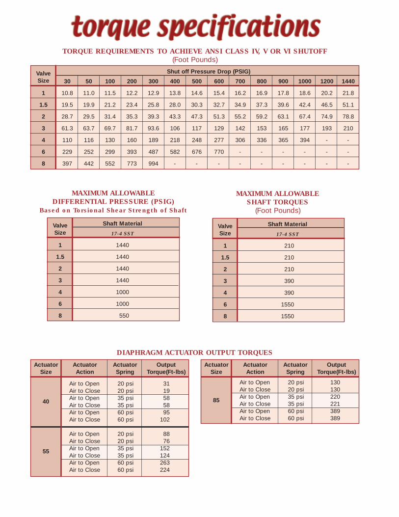
TORQUE REQUIREMENTS TO ACHIEVE ANSI CLASS IV, V OR VI SHUTOFF(Foot Pounds)
Shut off Pressure Drop (PSIG)ValveSize 30 50 100 200 300 400 500 600 700 800 900 1000 1200 1440
1 10.8 11.0 11.5 12.2 12.9 13.8 14.6 15.4 16.2 16.9 17.8 18.6 20.2 21.8
1.5 19.5 19.9 21.2 23.4 25.8 28.0 30.3 32.7 34.9 37.3 39.6 42.4 46.5 51.1
2 28.7 29.5 31.4 35.3 39.3 43.3 47.3 51.3 55.2 59.2 63.1 67.4 74.9 78.8
3 61.3 63.7 69.7 81.7 93.6 106 117 129 142 153 165 177 193 210
4 110 116 130 160 189 218 248 277 306 336 365 394 - -
6 229 252 299 393 487 582 676 770 - - - - - -
8 397 442 552 773 994 - - - - - - - - -
Shaft MaterialValveSize 17-4 SST
1 1440
1.5 1440
2 1440
3 1440
4 1000
6 1000
8 550
MAXIMUM ALLOWABLEDIFFERENTIAL PRESSURE (PSIG)
Based on Torsional Shear Strength of Shaft
DIAPHRAGM ACTUATOR OUTPUT TORQUES
MAXIMUM ALLOWABLESHAFT TORQUES
(Foot Pounds)
Actuator Actuator Actuator OutputSize Action Spring Torque(Ft-lbs)
Air to Open 20 psi 31Air to Close 20 psi 19Air to Open 35 psi 58Air to Close 35 psi 58Air to Open 60 psi 95Air to Close 60 psi 102
Air to Open 20 psi 88Air to Close 20 psi 76Air to Open 35 psi 152Air to Close 35 psi 124Air to Open 60 psi 263Air to Close 60 psi 224
40
55
Actuator Actuator Actuator OutputSize Action Spring Torque(Ft-lbs)
Air to Open 20 psi 130Air to Close 20 psi 130Air to Open 35 psi 220Air to Close 35 psi 221Air to Open 60 psi 389Air to Close 60 psi 389
85
Shaft MaterialValveSize 17-4 SST
1 210
1.5 210
2 210
3 390
4 390
6 1550
8 1550
Maximum ShutoffValveActuator Pressure DifferentialSizeCode Air Supply PSIG(Inches)
20 35 60DR-40-R-60 - - 1440
1 DR-40-R-35 - 1440 -DR-40-R-20 1440 - -DR-40-R-60 - - 1440
1.5 DR-40-R-35 - 1440 -DR-40-R-20 500 - -DR-40-R-60 - - 1440
2 DR-40-R-35 - 800 -DR-40-R-20 100 - -DR-55-R-60* - - 1440DR-55-R-35 - 775 -
3 DR-55-R-20 250 - -DR-85-R-35* - 1440 -DR-85-R-20 600 - -DR-55-R-60* - - 540DR-55-R-35 - 100 -
4 DR-55-R-20 25 - -DR-85-R-35* - 400 -DR-85-R-20 100 - -
6** DR-85-R-60 - - 200DR-85-R-35 - 25 -
8** DR-85-R-60 - - 25
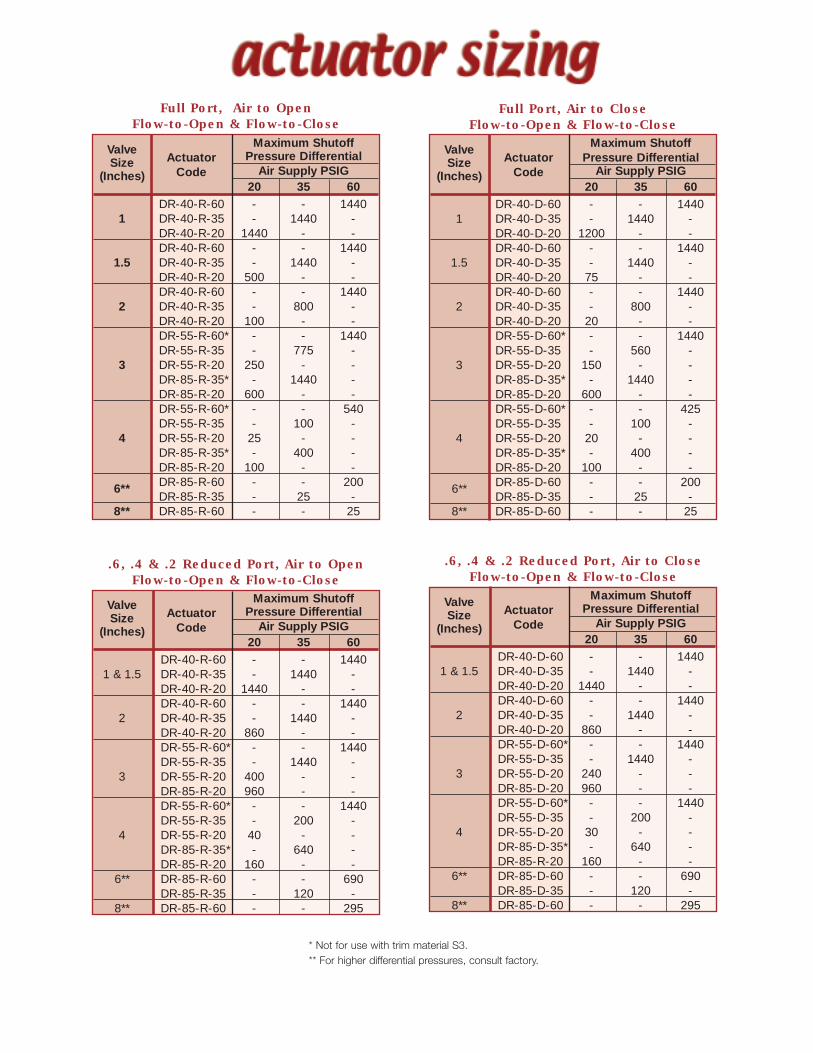
Full Port, Air to OpenFlow-to-Open & Flow-to-Close
Maximum ShutoffValveActuator Pressure DifferentialSizeCode Air Supply PSIG(Inches)
20 35 60DR-40-R-60 - - 1440
1 & 1.5 DR-40-R-35 - 1440 -DR-40-R-20 1440 - -DR-40-R-60 - - 1440
2 DR-40-R-35 - 1440 -DR-40-R-20 860 - -DR-55-R-60* - - 1440DR-55-R-35 - 1440 -
3 DR-55-R-20 400 - -DR-85-R-20 960 - -DR-55-R-60* - - 1440DR-55-R-35 - 200 -
4 DR-55-R-20 40 - -DR-85-R-35* - 640 -DR-85-R-20 160 - -
6** DR-85-R-60 - - 690DR-85-R-35 - 120 -
8** DR-85-R-60 - - 295
.6, .4 & .2 Reduced Port, Air to OpenFlow-to-Open & Flow-to-Close
Maximum ShutoffValveActuator Pressure DifferentialSizeCode Air Supply PSIG(Inches)
20 35 60DR-40-D-60 - - 1440
1 DR-40-D-35 - 1440 -DR-40-D-20 1200 - -DR-40-D-60 - - 1440
1.5 DR-40-D-35 - 1440 -DR-40-D-20 75 - -DR-40-D-60 - - 1440
2 DR-40-D-35 - 800 -DR-40-D-20 20 - -DR-55-D-60* - - 1440DR-55-D-35 - 560 -
3 DR-55-D-20 150 - -DR-85-D-35* - 1440 -DR-85-D-20 600 - -DR-55-D-60* - - 425DR-55-D-35 - 100 -
4 DR-55-D-20 20 - -DR-85-D-35* - 400 -DR-85-D-20 100 - -
6** DR-85-D-60 - - 200DR-85-D-35 - 25 -
8** DR-85-D-60 - - 25
Full Port, Air to CloseFlow-to-Open & Flow-to-Close
Maximum ShutoffValveActuator Pressure DifferentialSizeCode Air Supply PSIG(Inches)
20 35 60DR-40-D-60 - - 1440
1 & 1.5 DR-40-D-35 - 1440 -DR-40-D-20 1440 - -DR-40-D-60 - - 1440
2 DR-40-D-35 - 1440 -DR-40-D-20 860 - -DR-55-D-60* - - 1440DR-55-D-35 - 1440 -
3 DR-55-D-20 240 - -DR-85-D-20 960 - -DR-55-D-60* - - 1440DR-55-D-35 - 200 -
4 DR-55-D-20 30 - -DR-85-D-35* - 640 -DR-85-R-20 160 - -
6** DR-85-D-60 - - 690DR-85-D-35 - 120 -
8** DR-85-D-60 - - 295
.6, .4 & .2 Reduced Port, Air to CloseFlow-to-Open & Flow-to-Close
* Not for use with trim material S3.** For higher differential pressures, consult factory.
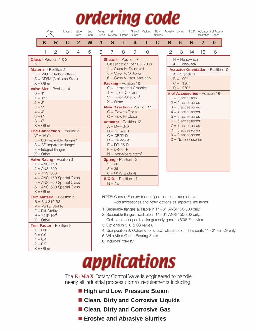
K R C 2 W 1 S 1 4 T C B 6 N 2 0
1 2 3 4 5 6 7 8 9 10 11 12 13 14 15 16
Class Material Valve End Valve Trim Trim Shutoff Packing Flow Actuator Spring H.O.D. Actuator # of Acces-Size Conn. Rating Material Factor Class Direction Orientation sories
NOTE: Consult Factory for configurations not listed above.Add accessories and other options as separate line items.
1. Separable flanges available in 1" - 6", ANSI 150-300 only.2. Separable flanges available in 1" - 6", ANSI 150-300 only.Carbon steel separable flanges only good to 800º F service.
3. Optional in 316 & CS valves.4. Use position 9, Option 6 for shutoff classification. TFE seats 1" - 2" Full Cv only.5. With Viton O-ring Bearing Seals.6. Includes Yoke Kit.
Shutoff - Position 9Classification (per FCI 70.2)4 = Class IV, Standard5 = Class V, Optional6 = Class VI, soft seat only
Packing - Position 10G = Laminated GraphiteT = Teflon-ChevronV = Teflon-Chevron4
X = OtherFlow Direction - Position 11O = Flow to OpenC = Flow to Close
Actuator - Position 12A = DR-40-DB = DR-40-RC = DR55-DD = DR-55-RE = DR-85-DF = DR-85-RN = None/bare stem5
Spring - Position 132 = 203 = 356 = 60 (Standard)
H.O.D. - Position 14N = No
Class - Position 1 & 2KR
Material - Position 3C = WCB (Carbon Steel)S = CF8M (Stainless Steel)X = Other
Valve Size - Position 40 = 1"1 = 11⁄2"2 = 2"3 = 3"4 = 4"6 = 6"8 = 8"X = Other
End Connection - Position 5W = WaferL = CS separable flanges2
S = SS separable flange1
F = Integral flangesX = Other
Valve Rating - Position 61 = ANSI 1502 = ANSI 3003 = ANSI 6004 = ANSI 150 Special Class5 = ANSI 300 Special Class6 = ANSI 600 Special ClassX = Other
Trim Material - Position 7S = Std 316 SSP = Partial StelliteF = Full StelliteR = 316/TFE4
X = OtherTrim Factor - Position 81 = Full6 = 0.64 = 0.42 = 0.2X = Other
H = HandwheelJ = HandJack
Actuator Orientation - Position 15A = StandardB = 90°C = 180°D = 270°
# of Accessories - Position 161 = 1 accessory2 = 2 accessories3 = 3 accessories4 = 4 accessories5 = 5 accessories6 = 6 accessories7 = 7 accessories8 = 8 accessories9 = 9 accessories0 = No accessories
The K-MAXK-MAX Rotary Control Valve is engineered to handlenearly all industrial process control requirements including:
� High and Low Pressure Steam
� Clean, Dirty and Corrosive Liquids
� Clean, Dirty and Corrosive Gas
� Erosive and Abrasive Slurries
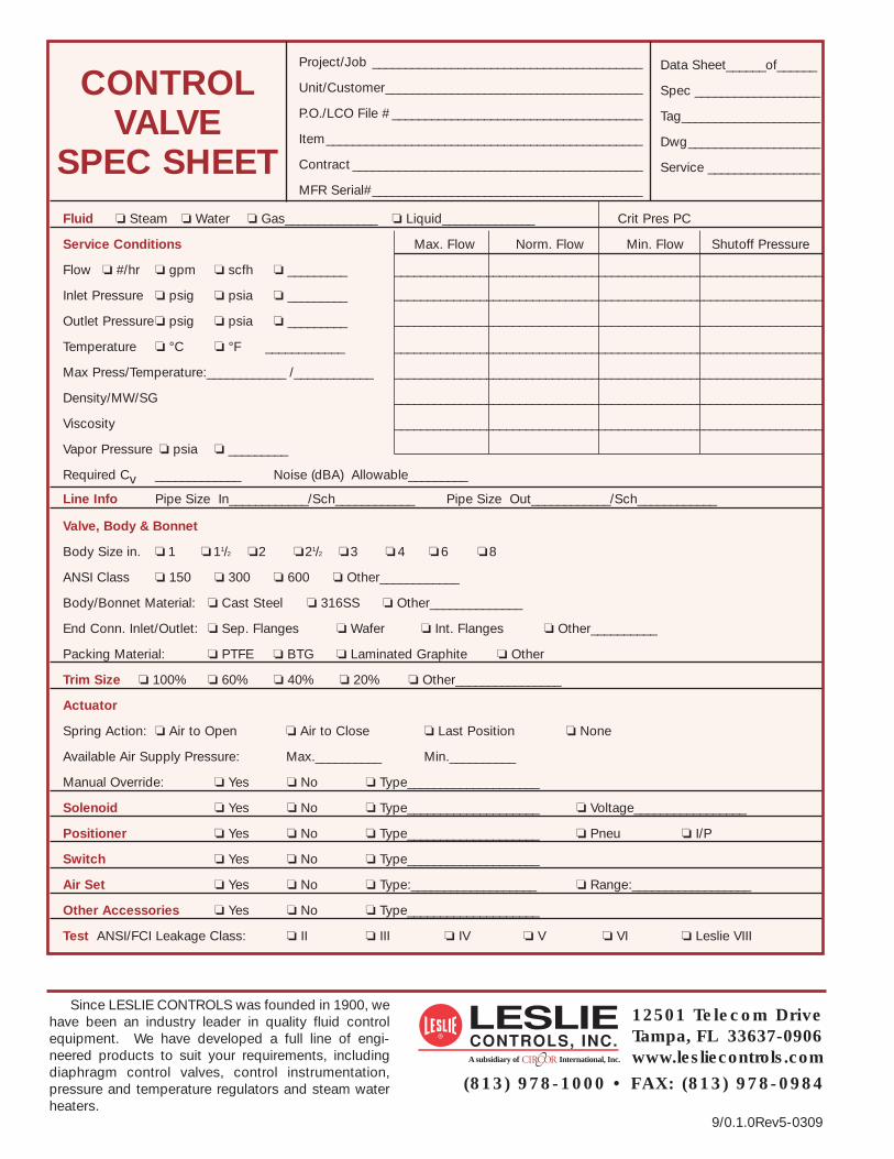
Project/Job _________________________________________ Data Sheet______of______
Unit/Customer_______________________________________ Spec ___________________
P.O./LCO File # ______________________________________ Tag_____________________
Item________________________________________________ Dwg____________________
Contract ____________________________________________ Service _________________
MFR Serial#_________________________________________
Fluid � Steam � Water � Gas______________ � Liquid______________ Crit Pres PC
Service Conditions Max. Flow Norm. Flow Min. Flow Shutoff Pressure
Flow � #/hr � gpm � scfh � _________ _________________________________________________________________
Inlet Pressure � psig � psia � _________ _________________________________________________________________
Outlet Pressure� psig � psia � _________ _________________________________________________________________
Temperature � °C � °F ____________ _________________________________________________________________
Max Press/Temperature:____________ /____________ _________________________________________________________________
Density/MW/SG _________________________________________________________________
Viscosity _________________________________________________________________
Vapor Pressure � psia � _________
Required Cv _____________ Noise (dBA) Allowable_________
Line Info Pipe Size In____________/Sch____________ Pipe Size Out____________/Sch____________
Valve, Body & Bonnet
Body Size in. � 1 � 11/2 �2 �21/2 �3 � 4 �6 �8
ANSI Class � 150 � 300 � 600 � Other____________
Body/Bonnet Material: � Cast Steel � 316SS � Other______________
End Conn. Inlet/Outlet: � Sep. Flanges � Wafer � Int. Flanges � Other__________
Packing Material: � PTFE � BTG � Laminated Graphite � Other
Trim Size � 100% � 60% � 40% � 20% � Other________________
Actuator
Spring Action: � Air to Open � Air to Close � Last Position � None
Available Air Supply Pressure: Max.__________ Min.__________
Manual Override: � Yes � No � Type____________________
Solenoid � Yes � No � Type____________________ � Voltage_________________
Positioner � Yes � No � Type____________________ � Pneu � I/P
Switch � Yes � No � Type____________________
Air Set � Yes � No � Type:___________________ � Range:__________________
Other Accessories � Yes � No � Type____________________
Test ANSI/FCI Leakage Class: � II � III � IV � V � VI � Leslie VIII
CONTROLVALVE
SPEC SHEET
Since LESLIE CONTROLS was founded in 1900, wehave been an industry leader in quality fluid controlequipment. We have developed a full line of engi-neered products to suit your requirements, includingdiaphragm control valves, control instrumentation,pressure and temperature regulators and steam waterheaters.
12501 Telecom DriveTampa, FL 33637-0906www.lesliecontrols.comA subsidiary of International, Inc.
(813) 978-1000 • FAX: (813) 978-0984
9/0.1.0Rev5-0309


![Home Page [] · ASTM D-2622 Karl Fischer ASTM D-86 ASTM D-1298 ASTM D6730 ASTM D6730 ASTM D6730 ASTM D4952 ASTM D130 ASTM D6730 Hexane Food Grade is manufactured to the high standards](https://img.dokumen.tips/doc/110x75/6007523cce6e086b945b7392/home-page-astm-d-2622-karl-fischer-astm-d-86-astm-d-1298-astm-d6730-astm-d6730.jpg)