Embed Size (px)
Citation preview

9 Valve terminals
2015/11 – Subject to change 779� www.festo.com/catalogue/...

Subject to change – 2015/11780 � www.festo.com/catalogue/...
� Standard valve terminals: valve modules to ISO 15407-1, 15407-2 andISO 5599-2 for standard valves with versatile valve functions and asplug-in or individual connection
� Universal valve terminals: sturdy and modular valve modules as a compact or modular sub-base for all standard tasks
� Application-specific valve terminals: space-saving and compact valve
modules for special requirements� Electrical peripherals: electric components for valve terminals and the
AS-Interface components� Accessories
9 Valve terminals >
2015/11 – Subject to change 781� www.festo.com/catalogue/...
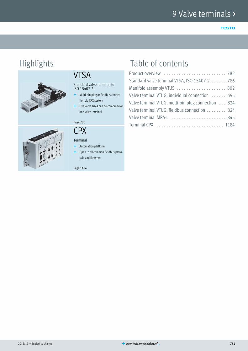
Highlights Table of contentsVTSAStandard valve terminal toISO 15407-2
� Multi-pin plug or fieldbus connec
tion via CPX system
� Five valve sizes can be combined on
one valve terminal
Page 786
Product overview 782. . . . . . . . . . . . . . . . . . . . . . . . .
Standard valve terminal VTSA, ISO 15407-2 786. . . . . .
Manifold assembly VTUS 802. . . . . . . . . . . . . . . . . . . .
Valve terminal VTUG, individual connection 695. . . . . .
Valve terminal VTUG, multi-pin plug connection 824. . .
Valve terminal VTUG, fieldbus connection 824. . . . . . . .
Valve terminal MPA-L 845. . . . . . . . . . . . . . . . . . . . . .
Terminal CPX 1184. . . . . . . . . . . . . . . . . . . . . . . . . . .
CPXTerminal
� Automation platform
� Open to all common fieldbus proto
cols and Ethernet
Page 1184
9 Valve terminals >

Subject to change – 2015/11782 � www.festo.com/catalogue/...
Product overview
Software tool
Product finder for valve
terminals
Find the right valve terminal quickly with the helpof the product finder. Start the product finder viathe blue icons in the product tree. Select yourtechnical features on the left-hand side step-by-step; the selection of suitable products on theright-hand side is automatically updated to reflectthe chosen technical features.
The use of logic checks ensures that only correct configurations are available for selection.The product finder for valve terminals is part of theelectronic catalogue and is not available as a separatesoftware program.
Standard valve terminals
Type
Valve terminal, ISO 154071
VTIA
Valve terminal, ISO 154072/ISO 55992
VTSA
Width 18 mm, 26 mm 18 mm, 26 mm, 42 mm, 52 mm
Standard nominal flow rate 400 ... 1400 l/min 400 ... 4000 l/min
Max. no of valve positions 16 32
Electrical actuation Individual connection Ethernet, fieldbus, multi-pin plug, electrical terminal CPX, integrated controller,individual connection, AS-Interface connection
Valve terminal design Modular, valve sizes can be mixed Modular, valve sizes can be mixed
Description � Conforms to ISO 15407-1� Wide range of individual electrical connections� Two valve sizes can be combined� Max. 16 valves
� Conforms to ISO 15407-2/ ISO 5599-2� Multi-pin plug or fieldbus connection via CPX system� Five valve sizes can be combined on one valve terminal� Integrated safety functions� Max. 32 valves
� Page/online vtia 786
Universal valve terminals
Type
Valve manifold
VTUS
Valve terminal with individual electric
al connection
VTUG
Valve terminal with multi-pin plug or
fieldbus connection
VTUG
Valve terminal
VTUB
Width 20 mm, 25 mm 10 mm, 14 mm 10 mm, 14 mm 12 mm, 24 mm
Standard nominal flow rate 600... 1300 l/min 80... 780 l/min 120 ... 630 l/min 200 ... 1000 l/min
Max. no of valve positions 16 16 24 16, 35
Electrical actuation Individual connection Individual connection Multi-pin plug, I-Port interface, IO-Link,fieldbus
Individual connection, fieldbus, multi-pin plug
Valve terminal design Fixed grid Fixed grid Fixed grid Fixed grid
Description � Robust VUVS valves with long servicelife
� Individual electrical connection� Pilot air supply in the manifold rail� Comprehensive range of accessories
� Compact with small VUVG valves� Connection technology easy to
change via the E-box� Wide range of valve functions� Also with semi-inline valves
� Low-cost fixed grid� Extremely easy assembly� Exchangeable electrical actuation� IO-Link capable� Valves VUVG with individual electric
al connection can be integrated� Also available with pneumatic mul
tiple connector plate� Max. 24 valves
� Low-cost fixed grid� Extremely easy assembly� Valves in polymer technology� Max. 16 valves� Electrical multi-pin plug connection
� Page/online 802 695 824 vtub
Valve terminals >
9

2015/11 – Subject to change 783� www.festo.com/catalogue/...
Product overview
Universal valve terminals
Type
Valve terminal
MPAL
Valve terminal
MPAS
Valve terminal
VTSAF
Valve terminal, Compact Performance
CPV
Width 10 mm, 14 mm, 20 mm 10 mm, 20 mm 18 mm, 26 mm 10 mm, 14 mm, 18 mm
Standard nominal flow rate 160 ... 870 l/min 360 ... 700 l/min 700 ... 1400 l/min 400 ... 1600 l/min
Max. no of valve positions 64 64 32 8
Electrical actuation Fieldbus, multi-pin plug, control block,electrical terminal CPX, IOLink,IPort
Fieldbus, multi-pin plug, control block,electrical terminal CPX, AS-Interface, CPinstallation system, individual connection
Ethernet, fieldbus, multi-pin plug, electrical terminal CPX, integrated controller, individual connection,AS-Interface connection
AS-Interface, CP installation system, individual connection, fieldbus, multi-pinplug, IO-Link, I-Port
Valve terminal design Modular, valve sizes can be mixed Modular, valve sizes can be mixed Modular, valve sizes can be mixed Modular
Description � Maximum modularity� Single granular� Polymer sub-base� 3 valve sizes� Max. 32 valves� Fieldbus connection via CPX� IO-Link capable
� Valve terminals for universal applications
� High-performance valves in a sturdymetal housing
� Metal linking� Two valve sizes can be combined� Excellent communication due to seri
al linking� Fieldbus connection via CPX� Max. 128 valves
� Flow rate-optimised VTSA valve terminal
� Linking with increased flow rates� Functions as per VTSA
� Maximum performance in the minimum of space
� Three sizes� Wide range of connection and mount
ing options� Multi-pin or fieldbus control� IO-Link capable
� Page/online 845 mpa-s vtsa cpv
Universal valve terminals
Type
Valve terminal, Smart Cubic
CPVSC
Valve manifold, Compact Performance
CPV10-EX-VI
Valve terminal
VTUB12
Width 10 mm 10 mm 12 mm
Standard nominal flow rate 170 l/min 0 ... 400 l/min 230 ... 400 l/min
Max. no of valve positions 16 8 35
Electrical actuation CP installation system, individual connection, fieldbus, multi-pin plug
Individual connection Multi-pin plug, I-Port interface, IO-Link, fieldbus
Valve terminal design Modular Fixed grid
Description � Small and compact� High flow rate even with compact design� Suitable for vacuum� Multi-pin or fieldbus control� Max. 16 valves
� Intrinsically safe valve manifold design to ATEXCategory 2 (Zone 1)
� Optimised for control cabinet assembly� Optimal for pilot control of process valves
� Compact dimensions� Poppet valves in polymer technology� Multi-pin or fieldbus control� IO-Link capable
� Page/online cpvsc cpv10-ex vtub-12
Valve terminals >
9

Subject to change – 2015/11784 � www.festo.com/catalogue/...
Product overview
Application-specific valve terminals
Type
Valve terminal
MPA-C
Valve terminal
VTOC
Valve terminal
MH1
Width 14 mm 10 mm 10 mm
Standard nominal flow rate 0 ... 780 l/min 10 l/min 10 ... 14 l/min
Max. no of valve positions 64 24 24
Electrical actuation Multi-pin, IO-Link, I-Port Multi-pin plug, I-Port interface, IO-Link, fieldbus Individual connection, multi-pin plug
Valve terminal design Modular, valve sizes can be mixed Fixed grid Fixed grid
Description � Valve terminals in Clean Design� Excellent corrosion resistance� Degree of protection IP69K� FDA-compliant materials� Redundant sealing system� Easy to clean� Max. 32 valves
� Compact pilot valves� Compact assembly� Greater safety by interlock function� Multi-pin or fieldbus control� IO-Link capable
� Miniaturised poppet valves� Multi-pin or electrical individual connection� Flow rate up to 14 l/min
� Page/online mpa-c vtoc mh1
Electrical peripherals
Type
Fieldbus module
CTEU
CPI installation system
CTEC
Terminal
CPX
Terminal
CPXP
Protocol AS-Interface, CANopen, CC-Link,DeviceNet, EtherCAT, PROFINET,PROFIBUS DP
INTERBUS, DeviceNet, PROFIBUS,CANopen, CC-Link, Ether-Net/IP,PROFINET, EtherCAT, ModbusTCP
INTERBUS, DeviceNet, PROFIBUS,CANopen, CC-Link, Ether-Net/IP,PROFINET, EtherCAT, ModbusTCP
DeviceNet, PROFIBUS, EtherNet/IP,PROFINET, ModbusTCP
Maximum address volume
for inputs
2 ... 64 byte 16 byte 64 byte 64 byte
Maximum address volume
for outputs
2 ... 64 byte 16 byte 64 byte 64 byte
Parameterisation Activate diagnostics, diagnostic behaviour, failsafe and idle response,failsafe response, watchdog disable,watchdog enable
Diagnostic behaviour, failsafe response,forcing of channels, signal setup
Diagnostic behaviour, failsafe response,forcing of channels, signal setup
Degree of protection IP65, IP67 IP65, IP67 IP65, IP67 IP20, IP65
Nominal DC operating voltage 24 ... 30 V 24 V 24 V 24 V
Operating voltage range
DC
18 ... 31.6 V 18 ... 30 V 18 ... 30 V 18 ... 30 V
Description � For valve terminals VTUB-12, VTUG,MPA-L, CPV, VTOC
� Can be expanded into installationsystems CTEL
� Fieldbus-typical LEDs, interfaces andswitching elements available
� Isolated power supply for electronicsand valves
� CPX Master module for four CPIstrings
� Combination of centralised and decentralised installation possible
� Decentralised pneumatic components and sensors for fast processes
� Can be connected to valve terminalCPV, MPA-S, CPV-SC
� Automation platform� Choice of polymer or metal housing
with individual linking� Open to all common fieldbus proto
cols and Ethernet� Integrated diagnostic and mainten
ance functions� Applicable as stand-alone as remote
I/O or with valve terminals MPA-S,MPA-L, VTSA/VTSA-F
� Use of harmonised remote I/O andvalve terminals in a control cabinet
� Unique modular structure� Comprehensive integrated diagnostic
and maintenance functions� Combination with modules of the
electrical terminal CPX, which enables use for hybrid applications
� Page/online cteu ctec 1184 cpx-p
Valve terminals >
9

2015/11 – Subject to change 785� www.festo.com/catalogue/...
Product overview
Electrical peripherals
Type
AS-Interface components
ASI-4DI3DO, ASI-8DI, ASI-EVA, ASI-PRG, CACC, CESA
Description � AS-i master gateway� Duplicate address recognition� Direct operation by pushbuttons� Graphic display� Comprehensive diagnostics via LED and display� Specification 3.0
� Page/online asi
Customised components – for your specific requirements
Valve terminals with customised designs
Can't find the valve terminal you need in our catalogue?We can offer you customised components that aretailored to your specific requirements – from minorproduct modifications to complete new product developments.
Common product modifications:� Coatings for special ambient conditions� Customised cables: length, pin allocation, pre-
assembled with plug� Modified actuating elements� Modified connecting thread� Modified valve sub-bases
Many additional variants are possible. Ask yourFesto sales engineer, who will be happy to help.Further information on customised componentscan be found on your local website at www.festo.com
Valve terminals >
9

Subject to change – 2015/11786 � www.festo.com/catalogue/...
Overview/Configuration/Ordering
� www.festo.com/catalogue/vtsaISO valve terminals
Valve terminals to ISO 15407-2/ISO 5599-2
Additional information/Support/User documentation
� www.festo.com/sp/vtsa VTSA
� Sturdy and flexible valve terminal� Valve widths 18 mm, 26 mm, 42 mm and 52 mm can be combined on a
single valve terminal without an adapter
� Integrated safety functions
Valve terminals >

2015/11 – Subject to change 787� www.festo.com/catalogue/...
Valve terminals VTSA, ISO 15407-2, ISO 5599-2
� Standard valve width 18/26/42/52/65 mm, flow rates up to
4000 l/min
� Combination of valve sizes possible
� Modular valve terminal for up to 32 valves
� Complete and standardised valve range
� Wide range of stacked valve assemblies: pressure regulator
plate, flow control plate, vertical pressure shut-off plate, etc.
� Sturdy metal design
� Repair service
� Channel-oriented diagnostics down to the individual valve
Product range overviewFunction Version Code Size � Page/
online18 mm
(ISO 02)
26 mm
(ISO 01)
42 mm
(ISO 1)
52 mm
(ISO 2)
65 mm
(ISO 3)
Position function 132 5/2-way valve, single solenoid, pneumatic spring return M � � � � � 792
5/2-way valve, single solenoid with spring return O � � � � � 792
5/2-way valve, double solenoid J � � � � � 792
5/2-way valve, double solenoid, dominant D � � � � � 792
2x3/2-way valve, normally open N � � � � – 792
2x3/2-way valve, normally closed K � � � � – 792
2x3/2-way valve, 1x normally closed, 1x normally open H � � � � – 792
5/3-way valve, mid-position pressurised B � � � � � 792
5/3-way valve, mid-position closed G � � � � � 792
5/3-way valve, mid-position exhausted E � � � � � 792
2x3/2-way valve, normally open, reverse operation P � � � � – 792
2x3/2-way valve, normally closed, reverse operation Q � � � � – 792
2x3/2-way valve, 1x normally closed, 1x normally open, reverse
operation
R � � � � – 792
2x2/2-way valve, normally closed VC � � � � – 792
2x2/2-way valve, normally closed, vacuum operation VV � � � – – 792
5/2-way control block with plug type C individual connection and
switching position sensing via PNP sensor, plug M8
SP – � – – – 792
5/2-way control block with plug type C individual connection and
switching position sensing via NPN sensor, plug M8
SN – � – – – 792
Note
Valve terminals can be ordered quickly and easily online.
The convenient product configurator can be found at:
� www.festo.com/catalogue/vtsa
Valve terminals > Standards-based valve terminals >
9
�www.festo.com/catalogue/ vtsa

Subject to change – 2015/11788 � www.festo.com/catalogue/...
Valve terminals VTSA, ISO 15407-2, ISO 5599-2
Product range overviewFunction Version Code Size � Page/
online18 mm
(ISO 02)
26 mm
(ISO 01)
42 mm
(ISO 1)
52 mm
(ISO 2)
65 mm
(ISO 3)
Position function 132 5/3-way valve, mid-position flow from 1 to 2, closed in 4 VG – – � � – vtsa
5/3-way valve, mid-position exhausted, switching position 14
detenting, 12 mechanical spring
SA – � – – – vtsa
5/3-way valve, mid-position port 2 pressurised, port 4 ex
hausted, switching position 14 detenting, 12 mechanical spring
SB – � – – – vtsa
5/3-way valve, mid-position port 4 pressurised, port 2 ex
hausted, switching position 14 detenting, 12 mechanical spring
SD � – – – – vtsa
5/3-way valve, mid-position exhausted, switching position 12
detenting, 14 mechanical spring
SE – � – – – vtsa
5/2-way valve, single solenoid, with spring return and switching
position sensing via PNP sensor, M8 plug
SO � � – – – vtsa
5/2-way valve, single solenoid, with spring return and switching
position sensing via NPN sensor, M8 plug
SQ � � – – – vtsa
5/2-way valve, single solenoid, with spring return and switching
position sensing via PNP sensor, 0.5 m cable and M8 plug
SS � � – – – vtsa
Vacuum block with ejector pulse and adjustable air saving func
tion (plate for 2 valve positions, sensor SDE3 with display and
M12 connection)
VB – � – – – vtsa
Vacant position L � � � � � vtsa
Note
Valve terminals can be ordered quickly and easily online.
The convenient product configurator can be found at:
� www.festo.com/catalogue/vtsa
Valve terminals > Standards-based valve terminals >
9

2015/11 – Subject to change 789� www.festo.com/catalogue/...
Valve terminals VTSA, ISO 15407-2, ISO 5599-2
Features
Innovative Versatile Reliable Easy to install
� High-performance valves in a sturdy
metal housing
� Five valve sizes on one valve terminal
(width 65 mm with adapter)
� Standardised from the multi-pin plug
to the fieldbus connection and control
block
� Dream team: fieldbus valve terminal
suitable for electrical peripherals CPX.
This means:
– Forward-looking internal commu
nication system for controlling the
valves and CPX modules
– Four valve sizes on one valve ter
minal without adapters
� Valve functions for integration in con
trol architectures of higher categories
to EN ISO 13849-1
� Modular system offering a range of
configuration options
� Expandable with up to 32 solenoid
coils
� Conversions and extensions are pos
sible at any time
� Manifold sub-bases can be extended
using four screws, sturdy duct separa
tion on metal support
� Integration of innovative function
modules possible
� Supply plates enable a flexible air
supply and variable pressure zones
� Reverse operation
� High pressure range
–0.9 … 10 bar, flow range
550 … 4000 l/min
� Wide range of valve functions
� Valve supply 24 V DC or 110 V AC
� Sturdy and durable metal components
– Valves
– Manifold sub-bases
– Seals
� Fast troubleshooting thanks to LEDs
on the valves and diagnostics via
fieldbus
� Reliable servicing thanks to valves
that can be replaced quickly and eas
ily
� Manual override, either non-detent
ing, non-detenting/detenting or
covered
� Durable thanks to tried-and-tested
piston spool valves
� Large and durable labelling system
� 100% duty cycle
� Ready-to-install and tested unit
� Reduced outlay on selection, ordering,
installation and commissioning
� Secure mounting on wall or H-rail
Electrical connection options
Multi-pin plug connection
Control signals from the controller to the
valve terminal are transmitted via a pre-
assembled multi-wire connecting cable
or a self-assembled multi-pin plug con
nection, which substantially reduces in
stallation time.
The valve terminal can be equipped with
max. 32 solenoid coils.
Versions
� Multi-pin plug connection with ter
minal strip (spring-loaded terminal)
� Connecting cable for multi-pin plug
connections, fully assembled (D-Sub)
� Sub-D plug connector for assembly by
the user, 37-pin
� Round plug connector M23, 19-pin
AS-Interface connection
A special feature of the AS-Interface is
the simultaneous transmission of data
and supply power via a two-wire cable.
The encoded cable profile prevents con
nection with incorrect polarity.
The valve terminal with AS-Interface is
available in the following versions:
� With one to eight modular valve posi
tions (max. 8 solenoid coils). This cor
responds to 1 to 8 VTSA valves.
� With all available valve functions.
The connection technology used for the
inputs can be selected as with CPX: M8,
M12, quick connector, Sub-D, spring-
loaded terminal (terminals to IP20).
Valve terminals > Standards-based valve terminals >
9
Subject to change – 2015/11790 � www.festo.com/catalogue/...
Valve terminals VTSA, ISO 15407-2, ISO 5599-2
Features
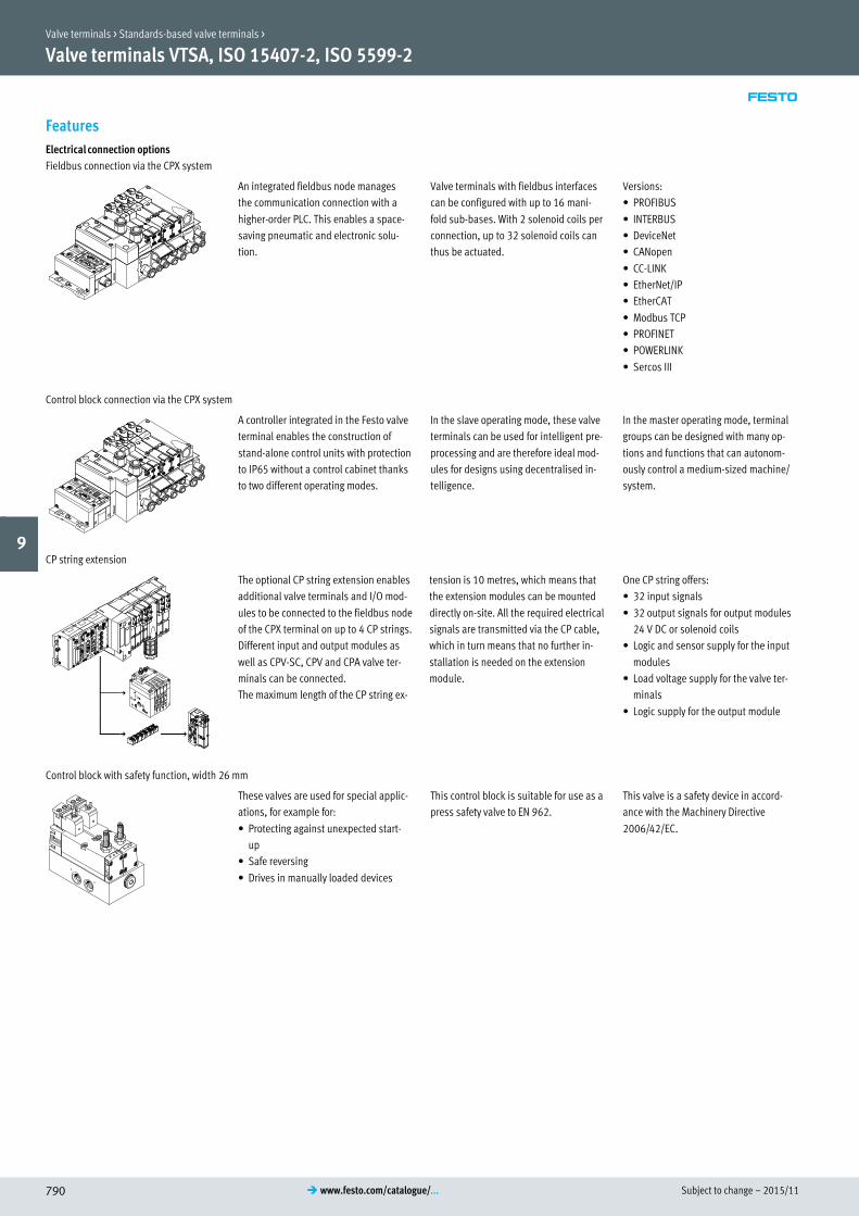
Electrical connection options
Fieldbus connection via the CPX system
An integrated fieldbus node manages
the communication connection with a
higher-order PLC. This enables a space-
saving pneumatic and electronic solu
tion.
Valve terminals with fieldbus interfaces
can be configured with up to 16 mani
fold sub-bases. With 2 solenoid coils per
connection, up to 32 solenoid coils can
thus be actuated.
Versions:
� PROFIBUS
� INTERBUS
� DeviceNet
� CANopen
� CC-LINK
� EtherNet/IP
� EtherCAT
� Modbus TCP
� PROFINET
� POWERLINK
� Sercos III
Control block connection via the CPX system
A controller integrated in the Festo valve
terminal enables the construction of
stand-alone control units with protection
to IP65 without a control cabinet thanks
to two different operating modes.
In the slave operating mode, these valve
terminals can be used for intelligent pre
processing and are therefore ideal mod
ules for designs using decentralised in
telligence.
In the master operating mode, terminal
groups can be designed with many op
tions and functions that can autonom
ously control a medium-sized machine/
system.
CP string extension
The optional CP string extension enables
additional valve terminals and I/O mod
ules to be connected to the fieldbus node
of the CPX terminal on up to 4 CP strings.
Different input and output modules as
well as CPV-SC, CPV and CPA valve ter
minals can be connected.
The maximum length of the CP string ex
tension is 10 metres, which means that
the extension modules can be mounted
directly on-site. All the required electrical
signals are transmitted via the CP cable,
which in turn means that no further in
stallation is needed on the extension
module.
One CP string offers:
� 32 input signals
� 32 output signals for output modules
24 V DC or solenoid coils
� Logic and sensor supply for the input
modules
� Load voltage supply for the valve ter
minals
� Logic supply for the output module
Control block with safety function, width 26 mm
These valves are used for special applic
ations, for example for:
� Protecting against unexpected start-
up
� Safe reversing
� Drives in manually loaded devices
This control block is suitable for use as a
press safety valve to EN 962.
This valve is a safety device in accord
ance with the Machinery Directive
2006/42/EC.
Valve terminals > Standards-based valve terminals >
9

2015/11 – Subject to change 791� www.festo.com/catalogue/...
Valve terminals VTSA, ISO 15407-2, ISO 5599-2
Features
Modular pneumatic components
The modular design of the VTSA/VTSA-F
enables maximum flexibility right from
the planning stage and offers maximum
ease of service in operation.
The system consists of manifold sub-
bases and valves.
The manifold sub-bases are screwed to
gether and thus form the support system
for the valves.
Inside the manifold sub-bases are the
connection ducts for supplying com
pressed air to and exhausting from the
valves on the terminal as well as the
working ports for the pneumatic cylin
ders for each valve.
Each manifold sub-base is connected to
the next using four screws.
Individual valve terminal sections can be
isolated and further manifold blocks in
serted by loosening these screws. This
ensures that the valve terminal can be
rapidly and reliably extended.
Modular electrical peripherals
The manner in which the valves are actu
ated differs according to whether you are
using a multi-pin terminal or fieldbus
terminal.
The VTSA/VTSA-F with CPX interface is
based on the internal bus system of the
CPX terminal and uses this communica
tion system for all solenoid coils and a
range of electrical input and output
functions.
Parallel linking enables the following:
� Transmission of switching information
� Compact design
� Position-based diagnostics
� Separate voltage supply for valves
� Flexible conversion without address
shifting
� Transmission of status, parameter and
diagnostic data
VTSA with electrical peripherals CPX Modularity with electrical peripherals CPX
Valve terminals > Standards-based valve terminals >
9

Subject to change – 2015/11792 � www.festo.com/catalogue/...
Valve terminals VTSA, ISO 15407-2, ISO 5599-2
Data sheet
-M- Flow rate
Up to 2900 l/min
-K- Valve width
18 mm
26 mm
42 mm
52 mm
-P- Operating voltage24 V DC
110 V AC
Technical data Download CAD data � www.festo.com
Design Piston spool valve
Width [mm] 18/26/42/52
Lubrication Life-time lubrication
Type of mounting Wall mounting
On H-rail to EN 60715
Manual override Detenting, non-detenting, covered
Pneumatic connection Via manifold sub-base
Supply port 1 G½, QS-G½-12, QS-G½-16
Exhaust port 3.5 G½, QS-G½-12, QS-G½-16
Working ports
(dependent on the connection type)
Width 18 mm (ISO 02) 2.4 Gx
Width 26 mm (ISO 01) 2.4 G¼
Width 42 mm (ISO 1) 2.4 Gy
Width 52 mm (ISO 2) 2.4 G½
External pilot air port 12, 14 G¼
Technical data Download CAD data � www.festo.com
Valve function/order code N K H P Q R M O J D B G E VC VV
Valve switching times [ms]
Width 18 mm (ISO 02),
nominal operating voltage 24 V DC/110 V AC
On 12 12 12 25 25 25 22 12 – – 15 15 15 12 12
Off 30 30 30 12 12 12 28 38 – – 44 44 44 30 30
Change-
over
– – – – – – – – 11 13 – – – – –
Width 26 mm (ISO 01)
nominal operating voltage 24 V DC/110 V AC
On 20 20 20 32 32 32 25 20 – – 22 22 22 20 20
Off 38 38 38 30 30 30 45 65 – – 65 65 65 38 38
Change-
over
– – – – – – – – 18 21 – – – – –
Width 42 mm (ISO 1)
nominal operating voltage 24 V DC
On 20 20 20 34 34 34 27 22 – – 22 22 22 20 20
Off 38 38 38 28 28 28 45 60 – – 65 65 65 38 38
Change-
over
– – – – – – – – 16 19 38 38 38 – –
Width 42 mm (ISO 1)
nominal operating voltage 110 V AC
On 22 22 22 34 34 34 20 20 – – 22 22 22 22 22
Off 46 46 46 38 38 38 55 55 – – 68 68 68 46 46
Change-
over
– – – – – – – – 16 19 41 41 41 – –
Width 52 mm (ISO 2)
nominal operating voltage 24 V DC
On 20 20 20 20 20 20 40 20 – – 23 23 23 14 –
Off 35 35 35 35 35 35 45 60 – – 60 60 60 35 –
Change-
over
– – – – – – – – 18 18 38 38 38 – –
Width 52 mm (ISO 2)
nominal operating voltage 110 V AC
On 35 35 35 50 50 50 70 25 – – 30 30 30 35 –
Off 70 70 70 65 65 65 90 110 – – 100 100 100 70 –
Change-
over
– – – – – – – – 35 42 60 60 60 – –
Standard nominal flow rate on valve terminal [l/min]
Width 18 mm (ISO 02) 400 550 450 500
Width 26 mm (ISO 01) 900 1100 1000 1000
Width 42 mm (ISO 1) 1200 1300 1200 1400
Width 52 mm (ISO 2) 2400 2900 2800 2800
Valve terminals > Standards-based valve terminals >
9

2015/11 – Subject to change 793� www.festo.com/catalogue/...
Valve terminals VTSA, ISO 15407-2, ISO 5599-2
Data sheet
Operating conditions
Valve function/order code N K H P Q R M O J D B G E VC VV
Operating medium Compressed air to ISO 8573-1:2010 [7:4:4]
Pilot medium Compressed air to ISO 8573-1:2010 [7:4:4]
Note on operating/pilot medium Lubricated operation possible (in which case lubricated operation will always be
required)
Ambient temperature [°C] –5 … +50
Temperature of medium [°C] –5 … +50
Operating pressure [bar] 3 … 10 –0.9 … +10 3 … 10 –0.9 … +10
Operating pressure for valve terminal with internal pilot air supply [bar] 3 … 10
Pilot pressure [bar] 3 … 10
Electrical data – VTSA with CPX terminal
Valve function/order code N K H P Q R M O J D B G E VC VV
Power supply for electronics (UEL/SEN)
Operating voltage [V DC] 24 ±10%
Max. intrinsic current consumption at 24 V
DC
[mA] 20
Duty cycle ED 100%
Load voltage supply for valves (Uval)
Operating voltage [V DC] 24 ±10%
Degree of protection to EN 60529 IP65, NEMA 4 (for all types of signal transmission in mounted state)
Power consumption Width 18 mm [W] 1.3 1.6 1.3 1.6 1.3
Width 26 mm [W] 1.3 1.6 1.3 1.6 1.3
Width 42 mm [W] 1.3 1.6 1.3 1.6 1.3
Width 52 mm [W] 4.6 4.6 4.6 4.6 4.6
Pneumatic connection sizes
Right-hand end plate (duct 12, 14) Code V, X G¼
Code V1, V3, X1, X3 G¼
Right-hand end plate (duct 1, 3, 5) Code V, X G½
Code V1, V3, X1, X3 G¾
Left-hand supply plate (duct 1, 3, 5) G½
Manifold sub-base (duct 2, 4) Width 18 mm Gx
Width 26 mm G¼
Width 42 mm Gy
Width 52 mm G½
Materials
Manifold sub-base Die-cast aluminium
Valve Die-cast aluminium, PA
Seals FPM, NBR, HNBR
Supply plate Die-cast aluminium
Right-hand end plate Die-cast aluminium
Pneumatic interface for CPX Die-cast aluminium
Flow control plate Die-cast aluminium
Pressure regulator plate Die-cast aluminium, PA
Multi-pin manifold block Die-cast aluminium
Cover for the pneumatic interface and multi-pin plug connection PA
Note on materials RoHS-compliant
Valve terminals > Standards-based valve terminals >
9

Subject to change – 2015/11794 � www.festo.com/catalogue/...
Valve terminals VTSA, ISO 15407-2, ISO 5599-2
Data sheet – Control block, VOFA
-M- Flow rate
Up to 950 l/min
-P- Operating voltage24 V DC
-L- Operating pressure
3 … 10 bar
Description
The control block is designed for two-
channel actuation of pneumatic drive
components such as double-acting lin
ear cylinders, for example, and can be
used to realise the following protective
measures:
� Protection against unexpected start-
up (EN 1037)
� Reversing hazardous movements,
provided the reversing motion will not
result in further hazards
The control attributes of the control
block enable Performance Level e to be
achieved for the protective measures.
The control block has been developed
and manufactured in accordance with
the basic and proven safety principles of
EN ISO 13849-1 and EN ISO 13849-2.
The requirements of EN ISO 13849-1 and
EN ISO 13849-2 (e.g. CCF, DC) must be
taken into consideration for implement
ation and operation of the component
and for use in higher categories (2 to 4).
When using this product in machines or
systems subject to specific C standards,
the requirements specified in these
standards must be observed.
The control block with safety function is
designed for installation in machines
and automation systems and must only
be used in industrial applications (high-
demand mode).
The control block with safety function is
suitable for use as a press safety valve to
EN 962.
More information and technical data
� Internet: User documentation
Decentralised individual connection variant Version for valve terminal VTSA/VTSA-F
Two solenoid valves on manifold sub-
base with square plugs to
EN 175301-803, type C and integrated
piston position sensing.
Two solenoid valves on manifold sub-
base for valve terminal VTSA/VTSA-F with
square plugs and integrated piston posi
tion sensing.
Electrical actuation takes place inde
pendently of the valve terminal (indi
vidual, multi-pin plug or fieldbus/control
block connection) via a standardised
square plug to EN 175301-803, type C.
Function – Pneumatic/electrical interlinking
The safety function is achieved through
two-channel pneumatic linking of two
5/2-way single-solenoid valves within the
control block: port 4 is only pressurised
if both solenoid valves are switched to
switching position (14).
Port 2 is always pressurised if at least
one of the two solenoid valves is in nor
mal position. The valve is reset via a
mechanical spring.
The switching operation of the solenoid
valves can be monitored by sensing via
the proximity sensors at the solenoid
valves (switching position sensing).
This is done by linking the control signal
and signal change of the proximity
sensor so that it is possible to check
whether the piston spools of the solenoid
valves are reaching or leaving the normal
position (expectations).
The piston spools of the solenoid valves
are designed so that pneumatic short cir
cuits between ports 2 and 4 are preven
ted (non-overlapping).
The two solenoid valves must be actu
ated via two separate ducts to achieve
the desired category 4 (Performance
Level e, to EN ISO 13849-1).
Valve terminals > Standards-based valve terminals >
9

2015/11 – Subject to change 795� www.festo.com/catalogue/...
Valve terminals VTSA, ISO 15407-2, ISO 5599-2
Data sheet – Control block, VOFA
Technical data Download CAD data � www.festo.com
Type VOFA-L26-T52-M-G14-1C1
(individual sub-base)
VOFA-B26-T52-M-1C1
(on valve terminal)
Design Piston spool valve
Sealing principle Soft
Actuation type Electrical
Type of pilot control Piloted
Pilot air supply Internal Internal/external via valve terminal
Type of mounting Via through-hole, on manifold sub-base
Mounting position Any
Manual override None
Valve switching status display Via accessories
Standard nominal flow rate [l/min] 950 830
Performance Level (PL) Protection against manipulation, prevention of unexpected start-up/up to category
4, Performance Level e
Reversing a movement/to category 4, Performance Level e
Switching times [ms]
Valve switching time On 22 22
Off 56 59
Valve sensor switching time1) On 60 60
Off 11 11
1) Valve sensor switching time off: period of time from coil being energised to sensor being switched off when using a PNP sensor.
Valve sensor switching time on: period of time from coil being de-energised to 0-L edge at the sensor when using a PNP sensor.
Operating conditions
Type VOFA-L26-T52-M-G14-1C1
(individual sub-base)
VOFA-B26-T52-M-1C1
(on valve terminal)
Operating medium Compressed air to ISO 8573-1:2010 [7:4:4]
Note on operating/pilot medium Lubricated operation possible (in which case lubricated operation will always be
required)
Ambient temperature [°C] –5 … +50
Temperature of medium [°C] –5 … +50
Operating pressure [bar] 3 … 10 0 … 10
Pilot pressure [bar] 3 … 10
Max. positive test pulse with logic 0 [μs] 1000
Max. negative test pulse with logic 1 [μs] 800
Valve terminals > Standards-based valve terminals >
9

Subject to change – 2015/11796 � www.festo.com/catalogue/...
Valve terminals VTSA, ISO 15407-2, ISO 5599-2
Data sheet – Control block, VOFA
Electrical data – Control block
Electrical connection Plug to EN 175301-803, type C, without protective conductor
Nominal operating voltage [V DC] 24
Power consumption [W] 1.8
Max. magnetic interference field [mT] 60
Switching position sensing Normal position via sensor
Duty cycle ED [%] 100
Degree of protection to EN 60529 IP65, NEMA 4 (for all types of signal transmission in mounted state)
Electrical data – Sensor
Electrical connection Cable, 3-wire
Plug M8x1, 3-pin
Cable length [m] 2.5
Switching output PNP or NPN
Switching element function N/C contact
Signal status display Yellow LED
Operating voltage range [V DC] 10 … 30
Sensor idle current [mA] Max. 10
Max. output current [mA] 200
Voltage drop [V] Max. 2
Max. switching frequency [Hz] 5000
Measuring principle Inductive
Connection sizes of the pneumatic connections
Type VOFA-L26-T52-M-G14-1C1
(individual sub-base)
VOFA-B26-T52-M-1C1
(on valve terminal)
Supply port 1 G¼ Via the manifold sub-base of the valve
terminalExhaust port 3/5, 33 G¼
Working ports 2/4 G¼
Pilot air supply 14 –
Pressure gauge G¼ G¼
Materials
Sub-base/manifold sub-base Wrought aluminium alloy
Valve Die-cast aluminium, PA
Seals FPM, NBR, HNBR
Screws Galvanised steel
Sensor housing High-alloy stainless steel
Sensor cable sheath PUR
Note on materials RoHS-compliant
Valve terminals > Standards-based valve terminals >
9

2015/11 – Subject to change 797� www.festo.com/catalogue/...
Valve terminals VTSA, ISO 15407-2, ISO 5599-2
Accessories
aH
aF
1
aBaC
5
1
6aG
9
9
aF
aC
aG
8
aI
aF
8
bA
bB
bC
7
aB aC
9
aE
aC
aC
9
aHaH
aH
aH
aH
aH
aH
4
2
aJ
aA
3
aD
bJ
aE
aE
Accessories � Page/online
1 Solenoid valve VSVA 792
2 Regulator plate VABF vtsa
3 Accessories for regulator plate (pressure gauge PAGN,
cartridge fitting QSP)
800
4 Additional stacked valve assemblies (flow control plate,
vertical supply plate or vertical pressure shut-off plate)
VABF
vtsa
5 Blanking plate VABB for vacant position vtsa
6 Right-hand end plate VABE with ports for supply air/ex
haust air
vtsa
7 Right-hand end plate VABE with pilot air selector vtsa
8 Manifold sub-base VABV vtsa
9 Duct separator VABD vtsa
aJ Electrical interface VABE for AS-Interface
(delivery unit with AS-Interface module VAEM)
vtsa-asi
aA AS-Interface module VAEM vtsa-asi
aB Cover cap VAMC for non-detenting/covered manual over
ride
800
aC Inscription label ASCF 800
Accessories � Page/online
aD Manifold block CPX-AB for AS-Interface vtsa-asi
aE Supply plate VABF with ducted exhaust air, ports 3 and
5 separated or combined
vtsa
aF Silencer U 800
aG Blanking plug B 800
aH Push-in fitting QS 800
aI Pneumatic interface VABA 1217
bJ Multi-pin plug connection NEBV/NECV with connecting
cable or cover for self-assembly
vtsa
bA Fieldbus interface CPX-FB 1185
bB Multi-pin plug connection VABE with terminal strip
(spring-loaded terminal)
vtsa
bC Multi-pin plug connection VABE with connecting cable
for multi-pin plug connections
vtsa
– Control block VOFA 801
– Wall mounting VAME 801
– 90° connection plate VABF 801
– User documentation P.BE-VTSA 801
Valve terminals > Standards-based valve terminals >
9

Subject to change – 2015/11798 � www.festo.com/catalogue/...
Valve terminals VTSA, to ISO 15407-2, ISO 5599-2
Accessories for valve with individual connection
In applications with specific emergency
off conditions, it may be necessary to
switch one or more valves separately
from the valve terminal controller. Stand
ard valves (VSVA) with individual elec
trical connection (round or square plug)
are mounted on the valve terminal to this
end.
In order for protection class IP65 to be
achieved, the functionless opening in the
sub-base for the electrical connection
must be sealed.
A sealing cap is available for the 18 mm
and 26 mm widths. With manifold or in
dividual sub-bases, valves with width 42
mm and 52 mm must be used with a seal
to comply with the IP degree of protec
tion.
For central control of the valve terminal
via a multi-pin plug or fieldbus connec
tion, the valve position occupied in this
way acts like a vacant position, i.e. the
assigned address in the fieldbus node or
the corresponding connection in the
multi-pin plug connection is occupied.
bE
bF
bD
bG
bH
bF
Accessories � Page/online
bD Sealing cap VABD vtsa
bE Solenoid valve to ISO15407-1 VSVA 659
bF Connecting cable NEBU vsva
bG Seal VABD-S2 vtsa
bH Solenoid valve to ISO5599-1 VSVA 676
– Control block VOFA 801
– Wall mounting VAME 801
– 90° connection plate VABF 801
– User documentation P.BE-VTSA 801
Valve terminals > Standards-based valve terminals >
9
2015/11 – Subject to change 799� www.festo.com/catalogue/...
Valve terminals VTSA, to ISO 15407-2, ISO 5599-2
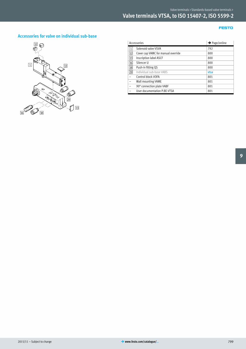
Accessories for valve on individual sub-base
aC
aB
1
aF aH
aC
bI
Accessories � Page/online
1 Solenoid valve VSVA 792
aB Cover cap VAMC for manual override 800
aC Inscription label ASCF 800
aF Silencer U 800
aH Push-in fitting QS 800
bI Individual sub-base VABS vtsa
– Control block VOFA 801
– Wall mounting VAME 801
– 90° connection plate VABF 801
– User documentation P.BE-VTSA 801
Valve terminals > Standards-based valve terminals >
9

Subject to change – 2015/11800 � www.festo.com/catalogue/...
Valve terminals VTSA, ISO 15407-2, ISO 5599-2
Accessories – Ordering dataCode1) Description Part no. Type
3 Accessories for regulator plate,
pressure gauge for widths 18 mm and 26 mm Technical data online: � pagn
U 6 bar,
for regulator plate code ZF,
ZG, ZH, ZI, ZJ, ZM, ZN
Widths 18 mm and 26 mm 543488 PAGN-26-10-P10
Widths 42 mm and 52 mm 548009 PAGN-40-10-P10
T 10 bar,
for regulator plate code ZA,
ZB, ZC, ZD, ZE, ZK, ZL
Widths 18 mm and 26 mm 543487 PAGN-26-16-P10
Widths 42 mm and 52 mm 548010 PAGN-40-16-P10
Cartridge fitting Technical data online: � qsp
– Adapter for pressure gauge
(allows products with threaded connection Gx to be attached to the cartridge fitting
connection)
565811 QSP10-Gx
– For tubing O.D. 4 mm 172972 QSP10-4
aB Cover cap for manual override
N Non-detenting 10 pieces 541010 VAMC-S6-CH
V Covered 10 pieces 541011 VAMC-S6-CS
aC Inscription label
B Clip-on for valve cap 5 pieces 540888 ASCF-T-S6
T For manifold blocks 5 pieces 540889 ASCF-M-S6
aF Silencer Technical data � 1237
– For thread Gx 6841 U-x-B
– For thread G¼ 2316 U-¼
– For thread G½ 6844 U-½-B
aG Blanking plug Technical data online: � b-1
– For thread Gx 10 pieces 3568 B-x
– For thread G¼ 10 pieces 3569 B-¼
aH Push-in fitting Technical data � 1098
– Connecting thread Gx For tubing O.D. 6 mm 10 pieces 186096 QS-Gx-6
– For tubing O.D. 8 mm 10 pieces 186098 QS-Gx-8
– Connecting thread G¼ For tubing O.D. 8 mm 10 pieces 186099 QS-G¼-8
– For tubing O.D. 10 mm 10 pieces 186101 QS-G¼-10
– Connecting thread Gy For tubing O.D. 10 mm 10 pieces 186102 QS-Gy-10
– For tubing O.D. 12 mm 10 pieces 186114 QS-Gy-12-I
– Connecting thread G½ For tubing O.D. 12 mm 1 piece 186104 QS-G½-12
– For tubing O.D. 16 mm 1 piece 186105 QS-G½-16
1) Code letter within the order code for a valve terminal configuration
Valve terminals > Standards-based valve terminals >
9

2015/11 – Subject to change 801� www.festo.com/catalogue/...
Valve terminals VTSA, ISO 15407-2, ISO 5599-2
Accessories – Ordering dataCode1) Description Part no. Type
Control block, individual connection variant Technical data online: � vofa
– PNP output 569819 VOFA-L26-T52-M-G14-1C1-APP
– NPN output 569820 VOFA-L26-T52-M-G14-1C1-ANP
Wall mounting
U Mounting bracket, with a mounting hole for M5 screw, 5 pieces 539214 VAME-S6-10-W
– Mounting bracket, with a mounting hole for M4 screw and a mounting hole for
M6 screw, 1 piece
567038 VAME-S6-W-M46
90° connection plate
P Width 18 mm, connecting thread Gx 539719 VABF-S4-2-A2G2-G18
Width 26 mm, connecting thread G¼ 539721 VABF-S4-1-A2G2-G14
Width 42 mm, connecting thread Gy 546097 VABF-S2-1-A1G2-G38
Width 52 mm, connecting thread G½ 555702 VABF-S2-2-A1G2-G12
User documentation
D German 538922 P.BE-VTSA-44-DE
E English 538923 P.BE-VTSA-44-EN
S Spanish 538924 P.BE-VTSA-44-ES
F French 538925 P.BE-VTSA-44-FR
I Italian 538926 P.BE-VTSA-44-IT
1) Code letter within the order code for a valve terminal configuration
Valve terminals > Standards-based valve terminals >
9

Subject to change – 2015/11802 � www.festo.com/catalogue/...
Overview/Configuration/Ordering
� www.festo.com/catalogue/vuvsUniversal directional control valves
Solenoid valve
Additional information/Support/User documentation
� www.festo.com/sp/vuvs VUVS
� Cost-effective� Easy to assemble and service thanks to the external pilot air supply via
manifold rail
� Easy to mount: available as ready-to-install individual valves with silencers, fittings and coils, or as pre-assembled units on a manifold rail VTUS
� Operating voltage can be easily adjusted using the rotatable coil, thus allowing the unit to fit in tight installation spaces
� Ideal for use in vacuum and the low-pressure range
Valve terminals >

2015/11 – Subject to change 803� www.festo.com/catalogue/...
Solenoid valves VUVS / Valve manifold VTUS
� A reliable, robust valve with a long service life
� Pre-assembled unit on manifold rails according to customer
configuration
� Individual valves assembled ready for installation according to
customer configuration
� Variable pressure zones
� Supply manifold for mounting on one/both sides
Product range overviewVersion Code Size � Page/
online20 25 30
3/2-way valve, normally closed, pneumatic spring M32C � � � 807, 809,
8113/2-way valve, normally closed, mechanical spring M32C � � �
3/2-way valve, normally open, pneumatic spring M32U � � �
3/2-way valve, normally open, mechanical spring M32U � � �
5/2-way valve, single solenoid, pneumatic spring M52 � � �
5/2-way valve, single solenoid, mechanical spring M52 � � �
5/2-way valve, double solenoid B52 � � �
5/3-way valve, mechanical spring, closed P53C � � �
5/3-way valve, mechanical spring, pressurised P53U � � �
5/3-way valve, mechanical spring, exhausted P53E � � �
Version Code Size � Page/
online20 25 30
Manifold block for 3/2-way valves, standard – � � � 814
Manifold block extension module for 3/2-way valves, standard – � � �
Manifold block for 5/2- and 5/3-way valves, standard – � � �
Manifold block extension module for 5/2- and 5/3-way valves, standard – � � �
Manifold block for 3/2-way valves, compact – � � �
Manifold block for 5/2- and 5/3-way valves, compact – � � �
Supply manifold, for mounting on both sides – � � �
Supply manifold, for mounting on one side – � � �
New Valve terminals > Universal valve terminals >
9
�www.festo.com/catalogue/ vuvs

Subject to change – 2015/11804 � www.festo.com/catalogue/...
Solenoid valves VUVS/valve manifold VTUS
Feature
Innovative Versatile Reliable Easy to install
� A reliable, robust valve with a long
service life
� Flow rate up to 1300 l/min
� Low-cost universal valve with no per
formance limitations
� Wide range of valve functions
� Operating voltage can be easily
altered by changing the solenoid coil
� In-line valves can be used as indi
vidual valves or manifold valves
� Variable pressure zones
� Wide range of mounting options
� Durable thanks to tried and tested
piston spools
� Reliable servicing thanks to valves
that can be replaced quickly and eas
ily
� Pre-assembled units on rails
� Individual valves assembled ready for
installation
� Supply manifolds for mounting on one
or both sides
� Secure mounting on wall or H-rail
Valve functions
3/2-way valve, normal position
open, single solenoid:
� Internal/external pilot air supply
� Reset via pneumatic/mechanical
spring
� Direction of flow can be reversed in
the case of external pilot air supply
3/2-way valve, normal position
closed, single solenoid:
� Internal/external pilot air supply
� Reset via pneumatic/mechanical
spring
� Direction of flow can be reversed in
the case of external pilot air supply
5/2-way valve, single solenoid:
� Internal/external pilot air supply
� Reset via pneumatic/mechanical
spring
� Direction of flow can be reversed in
the case of external pilot air supply
5/2-way valve, double solenoid:
� Internal/external pilot air supply
� Direction of flow can be reversed in
the case of external pilot air supply
5/3-way valve, mid-position exhausted,
pressurised or closed:
� Internal/external pilot air supply
� Reset via mechanical spring
� Direction of flow can be reversed in
the case of external pilot air supply
Features
� A maximum of 16 valve positions can
be configured in the standard version
� A maximum of 12 valve positions can
be configured in the compact version
� Valve positions 2 … 10 can be con
figured in increments of 1, valve posi
tions 10 … 16 in increments of 2
� Manifold block with a maximum of 10
valve positions
� Extension module with 2 valve posi
tions
� Supply manifold with a maximum of
10 valve positions
� Creation of pressure zones (maximum
9 pressure zones in the case of a valve
manifold with 16 valve positions)
Design
Each valve is attached to the manifold
block using two screws. The appropriate
seal is mounted on the valve.
This means that the valves can be easily
replaced.
Valve positions covered with blanking
plates can be replaced with valves at a
later date. The dimensions, mounting
points and existing pneumatic
installation remain unchanged.
For the standard manifold block, exten
sion modules with two valve positions
are available.
NewValve terminals > Universal valve terminals >
9

2015/11 – Subject to change 805� www.festo.com/catalogue/...
Solenoid valves VUVS/valve manifold VTUS
FeatureMounting valve manifold VTUS
Wall mounting
1
Sturdy wall mounting of the manifold
block using four through-holes.
1 Earth terminal
H-rail mounting
A
B
The H-rail mounting VAME-T-M con
sists of two mounting clips. These are
bolted to the manifold block on the left
and right.
The valve manifold VTUS is then
lowered onto the H-rail from above (ar
row A) and clipped into the H-rail at
the bottom (arrow B).
Note
� Note the max. tightening torque of
the screws for H-rail mounting.
� Only horizontal H-rail mounting is
permissible.
� Mounting possible on H-rail accord
ing to EN 60715.
� Vibration/shock loads are not per
missible with H-rail mounting.
Mounting individual valve VUVS
Wall mounting
For mounting individual valves on a
flat surface, e.g. aluminium profile sys
tems. The solenoid valves are provided
with two through-holes for attaching to
the wall mounting VAME-B10-20-W.
The relevant screw set is included
when the wall mounting VAME-
B10-20-W is ordered.
For mounting individual valves on a
flat surface, e.g. aluminium profile sys
tems.
The solenoid valves are provided with
two through-holes for attaching to the
foot mounting VAME-B10-…-A.
The relevant screw set is included
when the foot mounting VAME-
B10-…-A is ordered.
New Valve terminals > Universal valve terminals >
9

Subject to change – 2015/11806 � www.festo.com/catalogue/...
Solenoid valves VUVS/valve manifold VTUS
Data sheet
-M- Flow rate
Size 20:
up to 700 l/min
Size 25:
up to 1300 l/min
Size 30:
up to 2300 l/min
Technical data Download CAD data � www.festo.com
Valve manifold configura
tion
Fixed grid
Size 20
Valve width
Size 25
Valve width
Size 30
Valve width
[mm] 21
[mm] 26.5
[mm] 31
Valve design Piston spool valve
Electrical control Individual connection
Reset method for valves Pneumatic or mechanical spring
Pilot air supply Internal or external
Direction of flow Reversible with restrictions
Suitability for vacuum Yes
Max. no. of valve positions 16 (a maximum of 18 valve positions with extension for standard manifold block)
Max. number of pressure zones 9
Nominal operating voltage [V DC] 12, 24
[V AC] 24, 110, 120, 230, 240
Degree of protection IP65/IP67 with plug socket
To IEC 60529
Permissible voltage fluctu
ations
[%] _ 10
Information on materials for seals HNBR, NBR
NewValve terminals > Universal valve terminals >
9

2015/11 – Subject to change 807� www.festo.com/catalogue/...
Solenoid valves VUVS
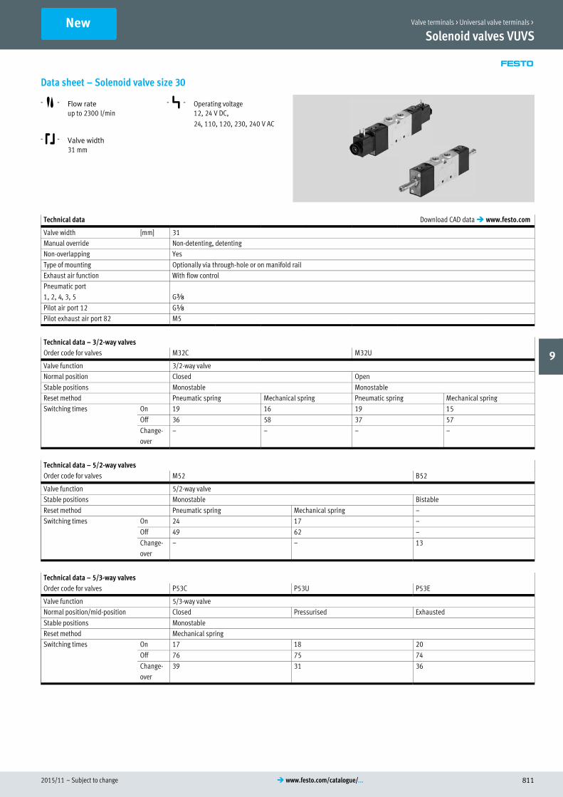
Data sheet – Solenoid valve size 20
-M- Flow rate
up to 700 l/min
-K- Valve width
21mm
-P- Operating voltage12, 24 V DC,
24, 110, 120, 230, 240 V AC
Technical data Download CAD data � www.festo.com
Valve width [mm] 21
Manual override Non-detenting, detenting
Sealing principle Soft
Type of mounting Optionally via through-hole or on manifold rail
Pneumatic port
1, 2, 4, 3, 5 Gx
Pilot air port 12 M5
Pilot exhaust air port 82 M5
Technical data – 3/2-way valves
Order code for valves M32C M32U
Valve function 3/2-way valve
Normal position Closed Open
Stable positions Monostable Monostable
Reset method Pneumatic spring Mechanical spring Pneumatic spring Mechanical spring
Switching times On 14 14 14 15
Off 21 32 21 28
Change-
over
– – – –
Technical data – 5/2-way valves
Order code for valves M52 B52
Valve function 5/2-way valve
Normal position – –
Stable positions Monostable Bistable
Reset method Pneumatic spring Mechanical spring –
Switching times On 20 12 –
Off 29 44 –
Change-
over
– – 10
Technical data – 5/3-way valves
Order code for valves P53C P53U P53E
Valve function 5/3-way valve
Normal position/mid-position Closed Pressurised Exhausted
Stable positions Monostable
Reset method Mechanical spring
Switching times On 13 13 13
Off 42 42 44
Change-
over
24 21 24
New Valve terminals > Universal valve terminals >
9

Subject to change – 2015/11808 � www.festo.com/catalogue/...
Solenoid valves VUVS
Data sheet – Solenoid valve size 20
Operating conditions
Order code for valves M32 M52 B52 P53
Operating medium Compressed air to ISO 8573-1:2010 [7:4:4]
Pilot medium Compressed air to ISO 8573-1:2010 [7:4:4]
Note on operating/pilot medium Operation with lubricated medium possible (in which case lubricated operation will always be required)
Operating pressure with internal
pilot air supply
[bar] 2.5 … 10 1.5 … 10 2.5 … 10
Operating pressure with ex
ternal pilot air supply
[bar] –0.9 … +10
Pilot pressure [bar] 2.5 … 10 1.5 … 10 2.5 … 10
Ambient temperature [°C] –10 … +60
Temperature of medium [°C] –10 … +60
Electrical data
With solenoid coil Without solenoid coil
Electrical connection Plug type C Via solenoid coil
� page 823Operating voltage [V DC] 24
Permissible voltage fluctuations [%] ±10
Performance [W] 2.5
Duty cycle ED [%] 100
Degree of protection to EN 60529 IP65 with plug socket
Information on materials
Housing Die-cast aluminium
Seals HNBR, NBR
Piston spool Wrought aluminium alloy
NewValve terminals > Universal valve terminals >
9

2015/11 – Subject to change 809� www.festo.com/catalogue/...
Solenoid valves VUVS
Data sheet – Solenoid valve size 25
-M- Flow rate
Up to 1300 l/min
-K- Valve width
26.5 mm
-P- Operating voltage12, 24 V DC,
24, 110, 120, 230, 240 V AC
Technical data Download CAD data � www.festo.com
Valve width [mm] 26.5
Manual override Non-detenting, detenting
Sealing principle Soft
Type of mounting Optionally via through-hole or on manifold rail
Pneumatic port
1, 2, 4, 3, 5 G¼
Pilot air port 12 M5
Pilot exhaust port 82 M5
Technical data – 3/2-way valves
Order code for valves M32C M32U
Valve function 3/2-way valve
Normal position Closed Open
Stable positions Monostable Monostable
Reset method Pneumatic spring Mechanical spring Pneumatic spring Mechanical spring
Switching times On 13 11 12 11
Off 26 40 26 39
Change-
over
– – – –
Technical data – 5/2-way valves
Order code for valves M52 B52
Valve function 5/2-way valve
Stable positions Monostable Bistable
Reset method Pneumatic spring Mechanical spring –
Switching times On 19 12 –
Off 35 47 –
Change-
over
– – 11
Technical data – 5/3-way valves
Order code for valves P53C P53U P53E
Valve function 5/3-way valve
Normal position/mid-position Closed Pressurised Exhausted
Stable positions Monostable
Reset method Mechanical spring
Switching times On 13 14 14
Off 42 48 48
Change-
over
26 25 25
New Valve terminals > Universal valve terminals >
9

Subject to change – 2015/11810 � www.festo.com/catalogue/...
Solenoid valves VUVS
Data sheet – Solenoid valve size 25Operating conditions
Order code for valves M32 M52 B52 P53
Operating medium Compressed air to ISO 8573-1:2010 [7:4:4]
Pilot medium Compressed air to ISO 8573-1:2010 [7:4:4]
Note on operating/pilot medium Lubricated operation possible (in which case lubricated operation will always be required)
Operating pressure with internal
pilot air supply
[bar] 2.5 … 10 1.5 … 10 2.5 … 10
Operating pressure with ex
ternal pilot air supply
[bar] –0.9 … +10
Pilot pressure [bar] 2.5 … 10 1.5 … 10 2.5 … 10
Ambient temperature [°C] –10 … +60
Temperature of medium [°C] –10 … +60
Electrical data
With solenoid coil Without solenoid coil
Electrical connection Plug type C, plug type B Via solenoid coil
� S. 823Operating voltage [V DC] 24
Permissible
voltage fluctuations
[%] 10
Performance [W] 3.3
Duty cycle ED [%] 100
Degree of protection to EN 60529 IP65 with plug socket
Information on materials
Housing Die-cast aluminium
Seals HNBR, NBR
Piston spool Wrought aluminium alloy
NewValve terminals > Universal valve terminals >
9
2015/11 – Subject to change 811� www.festo.com/catalogue/...
Solenoid valves VUVS
Data sheet – Solenoid valve size 30
-M- Flow rate
up to 2300 l/min
-K- Valve width
31 mm
-P- Operating voltage12, 24 V DC,
24, 110, 120, 230, 240 V AC
Technical data Download CAD data � www.festo.com
Valve width [mm] 31
Manual override Non-detenting, detenting
Non-overlapping Yes
Type of mounting Optionally via through-hole or on manifold rail
Exhaust air function With flow control
Pneumatic port
1, 2, 4, 3, 5 Gy
Pilot air port 12 Gx
Pilot exhaust air port 82 M5
Technical data – 3/2-way valves
Order code for valves M32C M32U
Valve function 3/2-way valve
Normal position Closed Open
Stable positions Monostable Monostable
Reset method Pneumatic spring Mechanical spring Pneumatic spring Mechanical spring
Switching times On 19 16 19 15
Off 36 58 37 57
Change-
over
– – – –
Technical data – 5/2-way valves
Order code for valves M52 B52
Valve function 5/2-way valve
Stable positions Monostable Bistable
Reset method Pneumatic spring Mechanical spring –
Switching times On 24 17 –
Off 49 62 –
Change-
over
– – 13
Technical data – 5/3-way valves
Order code for valves P53C P53U P53E
Valve function 5/3-way valve
Normal position/mid-position Closed Pressurised Exhausted
Stable positions Monostable
Reset method Mechanical spring
Switching times On 17 18 20
Off 76 75 74
Change-
over
39 31 36
New Valve terminals > Universal valve terminals >
9

Subject to change – 2015/11812 � www.festo.com/catalogue/...
Solenoid valves VUVS
Data sheet – Solenoid valve size 30Operating conditions
Order code for valves M32 M52 B52 P53
Operating medium Compressed air to ISO 8573-1:2010 [7:4:4]
Pilot medium Compressed air to ISO 8573-1:2010 [7:4:4]
Note on operating/pilot medium Operation with lubricated medium possible (in which case lubricated operation will always be required)
Operating pressure with internal
pilot air supply
[bar] 2.5 … 10 1.5 … 10 2.5 … 10
Operating pressure with ex
ternal pilot air supply
[bar] –0.9 … +10
Pilot pressure [bar] 2.5 … 10 1.5 … 10 2.5 … 10
Ambient temperature [°C] –10 … +60
Temperature of medium [°C] –10 … +60
Electrical data
With solenoid coil Without solenoid coil
Electrical connection Plug type C, plug type B Via solenoid coil
�S. 823Operating voltage [V DC] 24
Permissible
voltage fluctuations
[%] 10
Performance [W] 3.3
Duty cycle ED [%] 100
Degree of protection to EN 60529 IP65 with plug socket
Information on materials
Housing Die-cast aluminium
Seals HNBR, NBR
Piston spool Wrought aluminium alloy
NewValve terminals > Universal valve terminals >
9

2015/11 – Subject to change 813� www.festo.com/catalogue/...
Solenoid valves VUVS / Valve manifold VTUS
Order code – solenoid valve
VUVS – L – –
Valve design
In-line valve L
Size
21 mm 20
26.5 mm 25
31 mm 30
Valve functions
M32C
M32U
M52
B52
P53C
P53U
P53E
– – – –
Electrical connection
– Without
C1 Port pattern type C,
to EN 175301
Nominal operating voltage
– None
1 24 V DC
1A 24 V AC
3W 230/240 V AC
5 12 V DC
16B 113/120 V AC
Valve pilot control interface
F7 With 8 mm armature tube, short,
only with size 20
F8 With 8 mm armature tube, stand
ard, only with size 25 and 30
Exhaust
– Without fitting
QN With fitting
Pneumatic port
Q8 Push-in connector 8 mm
Manual override
D Non-detenting, detenting without accessories
S Covered
H Non-detenting
Reset method
A Pneumatic spring for M52 and M32
M Mechanical spring for M52 and M32
– For B52 and P53
Pilot air supply port
– Internal
Z External
Order example:
VUVS-L20-M32C-AD-Q8-F7-1C1
Universal solenoid valve VUVS in-line valve, width 20 (width 21 mm) - 3/2-way valve, single solenoid, normally closed - pneumatic spring reset method, internal pilot air supply,
non-detenting/detenting manual override without accessories - pneumatic connection push-in connector 8 mm - without fitting - with armature tube 8 mm, short - nominal oper
ating voltage 24 V DC, port pattern type C, to EN 175301
Ordering – Product options
Configurable
product
This product and all its options can
be ordered using the configurator.
The configurator can be found under
Products on the DVD or
� www.festo.com/catalogue/...
Enter the type code in the search field.
New Valve terminals > Universal valve terminals >
9
Subject to change – 2015/11814 � www.festo.com/catalogue/...
Solenoid valves VUVS / Valve manifold VTUS
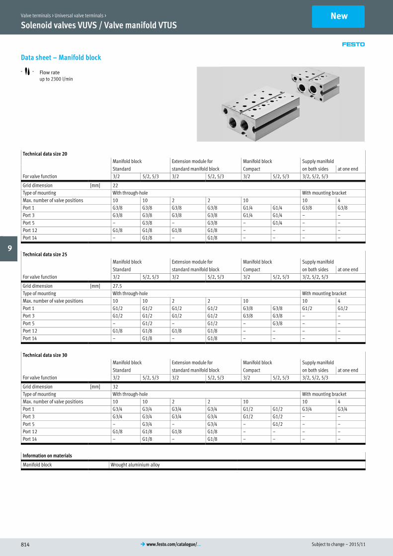
Data sheet – Manifold block
-M- Flow rate
up to 2300 l/min
Technical data size 20
Manifold block Extension module for Manifold block Supply manifold
Standard standard manifold block Compact on both sides at one end
For valve function 3/2 5/2, 5/3 3/2 5/2, 5/3 3/2 5/2, 5/3 3/2, 5/2, 5/3
Grid dimension [mm] 22
Type of mounting With through-hole With mounting bracket
Max. number of valve positions 10 10 2 2 10 10 4
Port 1 G3/8 G3/8 G3/8 G3/8 G1/4 G1/4 G3/8 G3/8
Port 3 G3/8 G3/8 G3/8 G3/8 G1/4 G1/4 – –
Port 5 – G3/8 – G3/8 – G1/4 – –
Port 12 G1/8 G1/8 G1/8 G1/8 – – – –
Port 14 – G1/8 – G1/8 – – – –
Technical data size 25
Manifold block Extension module for Manifold block Supply manifold
Standard standard manifold block Compact on both sides at one end
For valve function 3/2 5/2, 5/3 3/2 5/2, 5/3 3/2 5/2, 5/3 3/2, 5/2, 5/3
Grid dimension [mm] 27.5
Type of mounting With through-hole With mounting bracket
Max. number of valve positions 10 10 2 2 10 10 4
Port 1 G1/2 G1/2 G1/2 G1/2 G3/8 G3/8 G1/2 G1/2
Port 3 G1/2 G1/2 G1/2 G1/2 G3/8 G3/8 – –
Port 5 – G1/2 – G1/2 – G3/8 – –
Port 12 G1/8 G1/8 G1/8 G1/8 – – – –
Port 14 – G1/8 – G1/8 – – – –
Technical data size 30
Manifold block Extension module for Manifold block Supply manifold
Standard standard manifold block Compact on both sides at one end
For valve function 3/2 5/2, 5/3 3/2 5/2, 5/3 3/2 5/2, 5/3 3/2, 5/2, 5/3
Grid dimension [mm] 32
Type of mounting With through-hole With mounting bracket
Max. number of valve positions 10 10 2 2 10 10 4
Port 1 G3/4 G3/4 G3/4 G3/4 G1/2 G1/2 G3/4 G3/4
Port 3 G3/4 G3/4 G3/4 G3/4 G1/2 G1/2 – –
Port 5 – G3/4 – G3/4 – G1/2 – –
Port 12 G1/8 G1/8 G1/8 G1/8 – – – –
Port 14 – G1/8 – G1/8 – – – –
Information on materials
Manifold block Wrought aluminium alloy
NewValve terminals > Universal valve terminals >
9

2015/11 – Subject to change 815� www.festo.com/catalogue/...
Solenoid valves VUVS/valve manifold VTUS
Order code – Manifold block
VABM – B10 – –
Valve manifold parts
Connection block VABM
Valve series
VUVS B10
Valve width
21 mm 20
26.5 mm 25
31 mm 30
Version
Supply manifold –
Compact manifold block S
Standard manifold block E
Extension module for standard manifold block EEE
– – –
Connection
E Supply manifold for mounting at
one end
– Standard mounting
Port for valve function
– Manifold block for 5/2- and 5/3-way valves
P3 Manifold block for 3/2-way valves
P53 Supply manifold
Number of valve positions
2 … 10 2 to 10
Pneumatic connections 1, 3, 5
G38 G3/8 thread
G14 G1/4 thread
G12 G1/2 thread
G34 G3/4 thread
Order example:
VABM-B10-20E-G38-10
Manifold block for VUVS manifold assembly - valve width 21 mm, standard manifold block - thread G3/8 - 10 valve positions - manifold block for 5/2- and 5/3-way valves -
standard mounting
New Valve terminals > Universal valve terminals >
9

Subject to change – 2015/11816 � www.festo.com/catalogue/...
Solenoid valves VUVS/valve manifold VTUS
Accessories – Manifold assembly solenoid valve on manifold block
aD
1
2
3
9
aA
aB
aJ
5
7
8
6
7
7
8
8
aC
4
6
6
77
7
7
7
7
aD
Description Brief description � Page/online
1 H-rail mounting For H-rail mounting 818
2 Compact manifold block For 5/2- and 5/3-way valves, no port for external pilot air supply 818, 819, 820
3 Standard connection block For 5/2- and 5/3-way valves, with ports 12 and 14 for external pilot air supply 818, 819, 820
4 Extension module For standard manifold block, with ports 12 and 14 for external pilot air supply 818, 819, 820
5 Separator For creating pressure zones 821
6 Blanking plug – 821
7 Push-in fitting For connecting compressed air tubing with standard outside diameters 821
8 Silencer For mounting in exhaust ports 821
9 Supply plate For additional air supply and exhaust via a valve position 821
aJ Cover plate For covering unused valve positions 822
aA Illuminating seal For indicating the switching status 822
aB Plug socket with cable For solenoid valves VUVS 822
aC Plug socket For solenoid valves VUVS 822
aD Solenoid valve 5/2-way valve, with solenoid coil 807
aE H-rail – –
– Solenoid coil For solenoid valves VUVS 823
NewValve terminals > Universal valve terminals >
9

2015/11 – Subject to change 817� www.festo.com/catalogue/...
Solenoid valves VUVS/valve manifold VTUS
Accessories – Manifold assembly solenoid valve on supply manifoldSupply manifold for mounting on both sides Supply manifold for mounting on one side
9
aC
aD
aB
aJ
aA
8
5
6
7
7
7
7
7
aD
aD
aF
7
7
aB
68
9
aJ
aA
aD
aC
5
aF
7
77
7
7
7
aD
aD
7
Description Brief description � Page/online
5 Separator For creating pressure zones 821
6 Blanking plug – 821
7 Push-in fitting For connecting compressed air tubing with standard outside diameters 821
8 Silencer For mounting in exhaust ports 821
9 Supply plate For additional air supply via a valve position 821
aJ Cover plate For covering unused valve positions 822
aA Illuminating seal For indicating the switching status 822
aB Plug socket with cable For solenoid valves VUVS 822
aC Plug socket For solenoid valves VUVS 822
aD Solenoid valve With solenoid coil 807
aF Supply manifold – 823
– Solenoid coil For solenoid valves VUVS 823
New Valve terminals > Universal valve terminals >
9

Subject to change – 2015/11818 � www.festo.com/catalogue/...
Solenoid valves VUVS / Valve manifold VTUS
Accessories – Ordering dataDescription Part no. Type
1 H-rail mounting
For mounting the valve manifold on standard H-rail TH 35-7,5 or TH
35-15, to EN 60715
For size 20 569998 VAME-T-M4
For size 25 2636436 VAME-T-M5
For size 30 3488412 VAME-T-M6
2 Manifold block compact, size 20,
for 3/2-way valves
Incl. seals and screws for valve assembly 2 valve positions 576465 VABM-B10-20S-G14-2-P3
3 valve positions 576466 VABM-B10-20S-G14-3-P3
4 valve positions 576467 VABM-B10-20S-G14-4-P3
6 valve positions 576469 VABM-B10-20S-G14-6-P3
8 valve positions 576471 VABM-B10-20S-G14-8-P3
10 valve positions 576473 VABM-B10-20S-G14-10-P3
For 5/2- and 5/3-way valves
Incl. seals and screws for valve assembly 2 valve positions 576417 VABM-B10-20S-G14-2
3 valve positions 576418 VABM-B10-20S-G14-3
4 valve positions 576419 VABM-B10-20S-G14-4
6 valve positions 576421 VABM-B10-20S-G14-6
8 valve positions 576423 VABM-B10-20S-G14-8
10 valve positions 576425 VABM-B10-20S-G14-10
3 Manifold block standard, size 20,
for 3/2-way valves
Incl. seals and screws for valve assembly 2 valve positions 576441 VABM-B10-20E-G38-2-P3
3 valve positions 576442 VABM-B10-20E-G38-3-P3
4 valve positions 576443 VABM-B10-20E-G38-4-P3
6 valve positions 576445 VABM-B10-20E-G38-6-P3
8 valve positions 576447 VABM-B10-20E-G38-8-P3
10 valve positions 576449 VABM-B10-20E-G38-10-P3
For 5/2- and 5/3-way valves
Incl. seals and screws for valve assembly 2 valve positions 576339 VABM-B10-20E-G38-2
3 valve positions 576340 VABM-B10-20E-G38-3
4 valve positions 576341 VABM-B10-20E-G38-4
6 valve positions 576343 VABM-B10-20E-G38-6
8 valve positions 576345 VABM-B10-20E-G38-8
10 valve positions 576347 VABM-B10-20E-G38-10
4 Manifold block, extension module for standard manifold block, size 20
For 3/2-way valves, incl. seals and screws for valve assembly 2 valve positions 576490 VABM-B10-20EEE-G38-2-P3
For 5/2 and 5/3-way valves, incl. seals and screws for valve assembly 2 valve positions 576489 VABM-B10-20EEE-G38-2
NewValve terminals > Universal valve terminals >
9

2015/11 – Subject to change 819� www.festo.com/catalogue/...
Solenoid valves VUVS/valve manifold VTUS
Accessories – Ordering dataDescription Part no. Type
2 Manifold block compact, size 25,
for 3/2-way valves
Incl. seals and screws for valve assembly 2 valve positions 8026297 VABM-B10-25S-G38-2-P3
3 valve positions 8026298 VABM-B10-25S-G38-3-P3
4 valve positions 8026299 VABM-B10-25S-G38-4-P3
6 valve positions 8026301 VABM-B10-25S-G38-6-P3
8 valve positions 8026303 VABM-B10-25S-G38-8-P3
10 valve positions 8026305 VABM-B10-25S-G38-10-P3
For 5/2- and 5/3-way valves
Incl. seals and screws for valve assembly 2 valve positions 8026261 VABM-B10-25S-G38-2
3 valve positions 8026262 VABM-B10-25S-G38-3
4 valve positions 8026263 VABM-B10-25S-G38-4
6 valve positions 8026265 VABM-B10-25S-G38-6
8 valve positions 8026267 VABM-B10-25S-G38-8
10 valve positions 8026269 VABM-B10-25S-G38-10
3 Manifold block standard, size 25,
for 3/2-way valves
Incl. seals and screws for valve assembly 2 valve positions 8026279 VABM-B10-25E-G12-2-P3
3 valve positions 8026280 VABM-B10-25E-G12-3-P3
4 valve positions 8026281 VABM-B10-25E-G12-4-P3
6 valve positions 8026283 VABM-B10-25E-G12-6-P3
8 valve positions 8026285 VABM-B10-25E-G12-8-P3
10 valve positions 8026287 VABM-B10-25E-G12-10-P3
For 5/2- and 5/3-way valves
Incl. seals and screws for valve assembly 2 valve positions 8026243 VABM-B10-25E-G12-2
3 valve positions 8026244 VABM-B10-25E-G12-3
4 valve positions 8026245 VABM-B10-25E-G12-4
6 valve positions 8026247 VABM-B10-25E-G12-6
8 valve positions 8026249 VABM-B10-25E-G12-8
10 valve positions 8026251 VABM-B10-25E-G12-10
4 Extension module for standard manifold block, size 25
For 3/2-way valves, incl. seals and screws for valve assembly 2 valve positions 8026316 VABM-B10-25EEE-G12-2-P3
For 5/2 and 5/3-way valves, incl. seals and screws for valve assembly 2 valve positions 8026315 VABM-B10-25EEE-G12-2
New Valve terminals > Universal valve terminals >
9

Subject to change – 2015/11820 � www.festo.com/catalogue/...
Solenoid valves VUVS/valve manifold VTUS
Accessories – Ordering dataDescription Part no. Type
2 Manifold block compact, size 30,
for 3/2-way valves
Incl. seals and screws for valve assembly 2 valve positions 8026413 VABM-B10-30S-G12-2-P3
3 valve positions 8026414 VABM-B10-30S-G12-3-P3
4 valve positions 8026415 VABM-B10-30S-G12-4-P3
6 valve positions 8026417 VABM-B10-30S-G12-6-P3
8 valve positions 8026419 VABM-B10-30S-G12-8-P3
10 valve positions 8026421 VABM-B10-30S-G12-10-P3
For 5/2- and 5/3-way valves
Incl. seals and screws for valve assembly 2 valve positions 8026377 VABM-B10-30S-G12-2
3 valve positions 8026378 VABM-B10-30S-G12-3
4 valve positions 8026379 VABM-B10-30S-G12-4
6 valve positions 8026381 VABM-B10-30S-G12-6
8 valve positions 8026383 VABM-B10-30S-G12-8
10 valve positions 8026385 VABM-B10-30S-G12-10
3 Manifold block standard, size 30,
for 3/2-way valves
Incl. seals and screws for valve assembly 2 valve positions 8026395 VABM-B10-30E-G34-2-P3
3 valve positions 8026396 VABM-B10-30E-G34-3-P3
4 valve positions 8026397 VABM-B10-30E-G34-4-P3
6 valve positions 8026399 VABM-B10-30E-G34-6-P3
8 valve positions 8026401 VABM-B10-30E-G34-8-P3
10 valve positions 8026403 VABM-B10-30E-G34-10-P3
For 5/2- and 5/3-way valves
Incl. seals and screws for valve assembly 2 valve positions 8026359 VABM-B10-30E-G34-2
3 valve positions 8026360 VABM-B10-30E-G34-3
4 valve positions 8026361 VABM-B10-30E-G34-4
6 valve positions 8026363 VABM-B10-30E-G34-6
8 valve positions 8026365 VABM-B10-30E-G34-8
10 valve positions 8026367 VABM-B10-30E-G34-10
4 Extension module for standard manifold block, size 30
For 3/2-way valves, incl. seals and screws for valve assembly 2 valve positions 8026432 VABM-B10-30EEE-G34-2-P3
For 5/2 and 5/3-way valves, incl. seals and screws for valve assembly 2 valve positions 8026431 VABM-B10-30EEE-G34-2
NewValve terminals > Universal valve terminals >
9
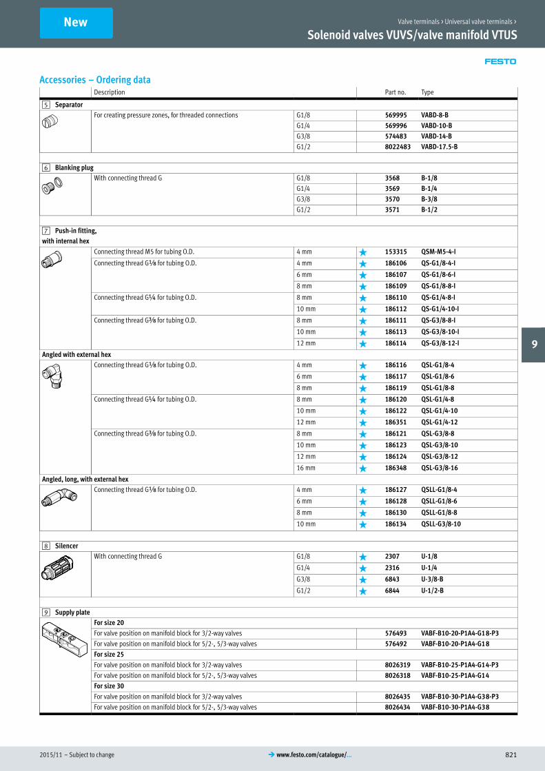
2015/11 – Subject to change 821� www.festo.com/catalogue/...
Solenoid valves VUVS/valve manifold VTUS
Accessories – Ordering dataDescription Part no. Type
5 Separator
For creating pressure zones, for threaded connections G1/8 569995 VABD-8-B
G1/4 569996 VABD-10-B
G3/8 574483 VABD-14-B
G1/2 8022483 VABD-17.5-B
6 Blanking plug
With connecting thread G G1/8 3568 B-1/8
G1/4 3569 B-1/4
G3/8 3570 B-3/8
G1/2 3571 B-1/2
7 Push-in fitting,
with internal hex
Connecting thread M5 for tubing O.D. 4 mm 153315 QSM-M5-4-I
Connecting thread Gx for tubing O.D. 4 mm 186106 QS-G1/8-4-I
6 mm 186107 QS-G1/8-6-I
8 mm 186109 QS-G1/8-8-I
Connecting thread G¼ for tubing O.D. 8 mm 186110 QS-G1/4-8-I
10 mm 186112 QS-G1/4-10-I
Connecting thread Gy for tubing O.D. 8 mm 186111 QS-G3/8-8-I
10 mm 186113 QS-G3/8-10-I
12 mm 186114 QS-G3/8-12-I
Angled with external hex
Connecting thread Gx for tubing O.D. 4 mm 186116 QSL-G1/8-4
6 mm 186117 QSL-G1/8-6
8 mm 186119 QSL-G1/8-8
Connecting thread G¼ for tubing O.D. 8 mm 186120 QSL-G1/4-8
10 mm 186122 QSL-G1/4-10
12 mm 186351 QSL-G1/4-12
Connecting thread Gy for tubing O.D. 8 mm 186121 QSL-G3/8-8
10 mm 186123 QSL-G3/8-10
12 mm 186124 QSL-G3/8-12
16 mm 186348 QSL-G3/8-16
Angled, long, with external hex
Connecting thread Gx for tubing O.D. 4 mm 186127 QSLL-G1/8-4
6 mm 186128 QSLL-G1/8-6
8 mm 186130 QSLL-G1/8-8
10 mm 186134 QSLL-G3/8-10
8 Silencer
With connecting thread G G1/8 2307 U-1/8
G1/4 2316 U-1/4
G3/8 6843 U-3/8-B
G1/2 6844 U-1/2-B
9 Supply plate
For size 20
For valve position on manifold block for 3/2-way valves 576493 VABF-B10-20-P1A4-G18-P3
For valve position on manifold block for 5/2-, 5/3-way valves 576492 VABF-B10-20-P1A4-G18
For size 25
For valve position on manifold block for 3/2-way valves 8026319 VABF-B10-25-P1A4-G14-P3
For valve position on manifold block for 5/2-, 5/3-way valves 8026318 VABF-B10-25-P1A4-G14
For size 30
For valve position on manifold block for 3/2-way valves 8026435 VABF-B10-30-P1A4-G38-P3
For valve position on manifold block for 5/2-, 5/3-way valves 8026434 VABF-B10-30-P1A4-G38
New Valve terminals > Universal valve terminals >
9

Subject to change – 2015/11822 � www.festo.com/catalogue/...
Solenoid valves VUVS/valve manifold VTUS
Accessories – Ordering dataDescription Part no. Type
aJ Blanking plate,
For size 20
For valve position on manifold block for 3/2-way valves 576411 VABB-B10-20-E-P3
For valve position on manifold block for 5/2-, 5/3-way valves 576410 VABB-B10-20-E
For valve position on supply manifold 576409 VABB-B10-20-A
For size 25
For valve position on manifold block for 3/2-way valves 8026210 VABB-B10-25-E-P3
For valve position on manifold block for 5/2-, 5/3-way valves 8026209 VABB-B10-25-E
For valve position on supply manifold 8026208 VABB-B10-25-A
For size 30
For valve position on manifold block for 3/2-way valves 8026336 VABB-B10-30-E-P3
For valve position on manifold block for 5/2-, 5/3-way valves 8026335 VABB-B10-30-E
For valve position on supply manifold 8026334 VABB-B10-30-A
aA Illuminating seal
Type C, to DIN EN 175301-803 24 V DC 151717 MEB-LD-12-24DC
230 V AC 151718 MEB-LD-230AC
aB Plug socket with cable
Port pattern type C, to DIN EN175301-803
Angled socket, 3-pin
Cable, open end, 3-wire, 24 V DC, LED
2.5 m 151688 KMEB-1-24-2,5-LED
5 m 151689 KMEB-1-24-5-LED
10 m 193457 KMEB-1-24-10-LED
Angled socket, 3-pin
Cable, open end, 3-wire, 0 … 230 V AC
2.5 m 151690 KMEB-1-230AC-2,5
5 m 151691 KMEB-1-230AC-5
Port pattern type B, to EN 175301-803
Angled socket, 3-pin
Cable, open end, 3-wire, 24 V DC, LED
2.5 m 30935 KMF124DC2,5LED
5 m 30937 KMF124DC5LED
10 m 193458 KMF12410LED
Angled socket, 3-pin
Cable, open end, 3-wire, 0 … 230 V AC
2.5 m 30936 KMF1230AC2.5
5 m 30938 KMF1230AC5
aC Plug socket
Port pattern type C, to DIN EN175301-803
Angled socket, 3-pin, IP65 0 … 230 V AC/DC 539712 MSSDEBM12
Angled socket, 4-pin, IP67 0 … 230 V AC/DC 192745 MSSDEBSM14
Angled socket, 3-pin, straight plug connector, M12, 2-pin, IP 65 12 … 24 V AC/DC 188024 MSSD-EB-M12-MONO
Port pattern type B, to EN 175301-803
Angled socket, 3-pin 0 … 230 V AC/DC 539710 MSSDFM16
Angled socket, 4-pin 0 … 230 V AC/DC 192746 MSSDFSM16
NewValve terminals > Universal valve terminals >
9

2015/11 – Subject to change 823� www.festo.com/catalogue/...
Solenoid valves VUVS/valve manifold VTUS
Accessories – Ordering dataDescription Part no. Type
aF Supply manifold,
size 20
For mounting on both sides, incl. seals and screws for mounting valves 2 valve positions 576363 VABM-B10-20-G38-2-P53
3 valve positions 576364 VABM-B10-20-G38-3-P53
4 valve positions 576365 VABM-B10-20-G38-4-P53
6 valve positions 576367 VABM-B10-20-G38-6-P53
8 valve positions 576369 VABM-B10-20-G38-8-P53
10 valve positions 576371 VABM-B10-20-G38-10-P53
For mounting on one side, incl. seals and screws for valve assembly 2 valve positions 576414 VABM-B10-20-G38-2-P53-E
3 valve positions 576415 VABM-B10-20-G38-3-P53-E
4 valve positions 576416 VABM-B10-20-G38-4-P53-E
Size 25
For mounting on both sides, incl. seals and screws for mounting valves 2 valve positions 8026219 VABM-B10-25-G12-2-P53
3 valve positions 8026220 VABM-B10-25-G12-3-P53
4 valve positions 8026221 VABM-B10-25-G12-4-P53
6 valve positions 8026223 VABM-B10-25-G12-6-P53
8 valve positions 8026225 VABM-B10-25-G12-8-P53
10 valve positions 8026227 VABM-B10-25-G12-10-P53
For mounting on one side, incl. seals and screws for valve assembly 2 valve positions 8026237 VABM-B10-25-G12-2-P53-E
3 valve positions 8026238 VABM-B10-25-G12-3-P53-E
4 valve positions 8026239 VABM-B10-25-G12-4-P53-E
Size 30
For mounting on both sides, incl. seals and screws for mounting valves 2 valve positions 8026338 VABM-B10-30-G34-2-P53
3 valve positions 8026339 VABM-B10-30-G34-3-P53
4 valve positions 8026340 VABM-B10-30-G34-4-P53
6 valve positions 8026342 VABM-B10-30-G34-6-P53
8 valve positions 8026344 VABM-B10-30-G34-8-P53
10 valve positions 8026346 VABM-B10-30-G34-10-P53
For mounting on one side, incl. seals and screws for valve assembly 2 valve positions 8026356 VABM-B10-30-G34-2-P53-E
3 valve positions 8026357 VABM-B10-30-G34-3-P53-E
4 valve positions 8026358 VABM-B10-30-G34-4-P53-E
Solenoid coil for valves
For size 20
Port pattern type C, to DIN EN 175301-803 12 V DC 8025331 VACS-C-C1-5
24 V DC 8025330 VACS-C-C1-1
48 V DC 8025336 VACS-C-C1-7
24 V AC 8025335 VACS-C-C1-1A
48 V AC 8025337 VACS-C-C1-7A
110/120 V AC 8025334 VACS-C-C1-16B
230/240 V AC 8025338 VACS-C-C1-3W
For size 25 and size 30
Plug pattern type B, industry standard 12 V DC 8030801 VACF-B-B2-5
24 V DC 8030802 VACF-B-B2-1
48 V DC 8030803 VACF-B-B2-7
24 V AC 8030804 VACF-B-B2-1A
48 V AC 8030805 VACF-B-B2-7A
110/120 V AC 8030806 VACF-B-B2-16B
230/240 V AC 8030808 VACF-B-B2-3W
Port pattern type C, to EN 175301 12 V DC 8030810 VACF-B-C1-5
24 V DC 8030811 VACF-B-C1-1
48 V DC 8030812 VACF-B-C1-7
24 V AC 8030813 VACF-B-C1-1A
48 V AC 8030814 VACF-B-C1-7A
110/120 V AC 8030815 VACF-B-B2-16B
230/240 V AC 8030817 VACF-B-C1-3W
New Valve terminals > Universal valve terminals >
9

Subject to change – 2015/11824 � www.festo.com/catalogue/...
Overview/Configuration/Ordering
� www.festo.com/catalogue/vtugUniversal valve terminals
Valve terminals multi-pin/fieldbus connection
Additional information/Support/User documentation
� www.festo.com/sp/vtug VTUG
� Sturdy and durable metal components� Excellent price/performance ratio� Connection M5, M7, G1/8
� Push-in connector 3, 4, 6, 8 mm� Degree of protection IP40/IP67
Valve terminals >

2015/11 – Subject to change 825� www.festo.com/catalogue/...
Valve terminals VTUG with multi-pin plug and fieldbus connection
� Variable multi-pin plug connection using Sub-D or flat cable
� I-Port interface for bus nodes (CTEU)
� IO-Link mode for direct connection to a higher-level IO-Link
master
� Valve size 10 mm, 14 mm and 18 mm
� Sub-D variant and fieldbus connection rated to IP67
� Piston spool valves, up to 24 valve positions
�Quick ordering of basic designs � 831, 833, 835, 837
Product range overviewFunction Version Code Valve size � Page/
online10 mm 14 mm 18 mm
Position function 123 5/2-way valve, single solenoid, mechanical spring A � � � 829
5/2-way valve, single solenoid, pneumatic/mechanical spring P � – – 829
5/3-way valve, mid-position pressurised B � � � 829
5/3-way valve, mid-position exhausted E � � � 829
5/3-way valve, mid-position closed G � � � 829
2x3/2-way valve, 1x normally closed, 1x normally open, pneumatic spring H � � � 829
5/2-way bistable valve J � � � 829
2x3/2-way valve, normally closed, pneumatic spring C � � � 829
5/2-way valve, single solenoid, pneumatic spring M – � � 829
2x3/2-way valve, normally open, pneumatic spring N � � � 829
2x3/2-way valve, 1x normally closed, 1x normally open, mechanical spring VH � � � 829
2x3/2-way valve, normally closed, mechanical spring VK � � � 829
2x3/2-way valve, normally open, mechanical spring VN � � � 829
3/2-way valve, normally closed, external compressed air supply VX � � � vtug
3/2-way valve, normally open, external compressed air supply VW � � � vtug
Additional power supply S � � � 829
Vacant position L � � � 829
Note
Valve terminals can be ordered quickly and easily online.
The convenient product configurator can be found at:
� www.festo.com/catalogue/vtug
Valve terminals > Universal valve terminals >
9
�www.festo.com/catalogue/ vtug

Subject to change – 2015/11826 � www.festo.com/catalogue/...
Valve terminals VTUG with multi-pin plug and fieldbus connection
FeaturesInnovative Versatile Reliable Easy to mount
� Festo-specific I-Port interface for bus
nodes (CTEU)
� IO-Link mode for direct connection to
a higher-level IO-Link master
� Festo-specific I-Port interface with in
terlock
� Variable multi-pin plug connection us
ing Sub-D or flat cable
� Reversible piston spool valves, up to
24 valve positions
� Reduced power consumption
� Excellent price/performance ratio
� Choice of quick plug connectors
� Multiple pressure zones possible
� Sub-D variant and fieldbus connection
rated to IP67
� Internal or external pilot air with the
same manifold rail possible through
the use of blanking plugs
� Sub-base valves with working ports
underneath for installation in control
cabinets
� Sturdy and durable metal components
– Valves
– Manifold rails
� Fast troubleshooting thanks to LED
display
� Choice of manual override: non-de
tenting, detenting or covered
� Easy mounting thanks to captive
screws and seal
� Connection technology easy to change
� Inscription label holder for labelling
Sub-base and semi in-line valves
VUVG-S…1T1
Semi in-line valve
Sub-base valve
VUVG-B…1T1
Valve terminal VTUG with variable elec
trical connection
Overview
Variable electrical connection: flat cable or Sub-D
CTEU bus node
Variable electrical connection:
I-Port interface
Equipment options
Valve functions
� 2x3/2-way, 5/2-way, 5/3-way valves � Reversible piston spool valves, up to
24 valve positions
� IO-Link mode for direct connection to
a higher-level IO-Link master
� Festo-specific I-Port interface for bus
nodes (CTEU)
� Variable multi-pin plug connection us
ing Sub-D or flat cable
� Festo-specific I-Port interface with in
terlock (for valves of valve size
10 mm)
Valve terminals > Universal valve terminals >
9

2015/11 – Subject to change 827� www.festo.com/catalogue/...
Valve terminals VTUG with multi-pin plug and fieldbus connection
Features
Basic valves VUVG
� Valve size 10 mm and 14 mm
� Semi in-line valves
� Sub-base valves
� 2x3/2-way, 5/2-way and 5/3-way
valves
Electrical connection
Multi-pin plug connection
The signals are transmitted from the
controller to the valve terminal via a pre-
assembled or self-assembled multi-wire
cable to the multi-pin plug connection,
which substantially reduces installation
time. The valve terminal can be
equipped with max. 48 solenoid coils.
Versions:
� Sub-D connection
� Flat cable
I-Port interface
Festo-specific interface as a basis for
bus nodes (CTEU) or in IO-Link mode
for direct connection to a higher-level
IO-Link master.
Communication and power supply take
place via a common M12 interface on
the terminal.
Connection options:
� As I-Port interface for bus nodes
(CTEU)
� In IO-Link mode for direct connection
to an IO-Link master
Manifold rails
For semi in-line valves For sub-base valves
� For semi in-line valves, M5, M7, valve
width 10 mm and G1/8, valve width
14 mm
� For 2x3/2-way, 5/2-way and 5/3-way
valves
� 4 to 24 valve positions with electrical
interlinking
� The semi in-line valves are always
supplied with external pilot air. The
pilot air is set via the manifold rail. A
short and a long blanking plug are in
cluded with the manifold rail for this
purpose.
� For sub-base valves M5/M7, valve
width 10 mm and G1/8, valve width
14 mm
� For 2x3/2-way, 5/2-way and 5/3-way
valves
� 4 to 24 valve positions with electrical
interlinking
� The sub-base valves are always sup
plied with external pilot air. The pilot
air is set via the manifold rail. A short
and a long blanking plug are included
with the manifold rail for this purpose.
Valve terminals > Universal valve terminals >
9

Subject to change – 2015/11828 � www.festo.com/catalogue/...
Valve terminals VTUG with multi-pin plug and fieldbus connection
Features
� Communication with the higher-order
controller via fieldbus
� Use a bus node CTEU compatible with
the fieldbus protocol
� Up to 64 inputs/outputs (solenoid
coils), depending on the valve ter
minal
� No preprocessing
System overview – IO-Link
PLC
Fieldbus
CTEU node
IO-Link
I-Port interface
Valve terminals > Universal valve terminals >
9

2015/11 – Subject to change 829� www.festo.com/catalogue/...
Valve terminals VTUG with multi-pin plug and fieldbus connection
Data sheet – Semi in-line valve M5/M7
-K- Valve size 10 mm
-M- Flow rate
130 … 330 l/min
-P- Operating voltage24 V DC
Technical data Download CAD data � www.festo.com
Valve function T32-A T32-M M52-R B52 M52-M P53
Normal position C1) U2) H4) C1) U2) H4) – – – C1) U2) E3)
Pneumatic spring reset method Yes No Yes5) – No –
Mechanical spring reset method No Yes Yes5) – Yes –
Stable positions Monostable Bistable Monostable
Port 1, 3, 5 On manifold rail
Port 2, 4 VUVG-S10-…-M5 M5
Port 2, 4 VUVG-S10-…-M7 M7
Port 12, 14 On manifold rail
Flow rate on manifold rail M5 [l/min] 150 130 230 230 230 210
Flow rate on manifold rail M7 [l/min] 160 140 330 330 290 280
Vacuum operation at port 1 No With external pilot air supply
Design Piston spool valve
Type of mounting On manifold rail
Electrical connection Via sub-base
Manual override Choice of non-detenting, covered, non-detenting/detenting or detenting
1) C=Normally closed.
2) U=Normally open/mid-position pressurised.
3) E=Normally exhausted.
4) H=2x 3/2-way valve in one housing with 1x normally closed and 1x normally open.
5) Combined reset method.
Operating conditions
Valve function T32-A6 T32-M7 M52-R8 B52 M52-M7 P53
Operating medium Compressed air to ISO 8573-1:2010 [7:4:4]
Operating pressure Internal pilot air supply [bar] 1.5 … 8 2 … 8 2.5 … 8 1.5 … 8 3 … 8 3 … 8
External pilot air supply [bar] 1.5 … 10 –0.9 … 10 –0.9 … 10 –0.9 … 10 –0.9 … 8 –0.9 … 10
Pilot pressure9) 1.5 … 8 2 … 8 2.5 … 8 1.5 … 8 3 … 8 3 … 8
Ambient temperature [°C] –5 … +60
Temperature of medium [°C] –5 … +60
6) Pneumatic spring.
7) Mechanical spring.
8) Pneumatic/mechanical spring.
9) Minimum pilot pressure 50% of operating pressure.
Materials
Housing Wrought aluminium alloy
Seals HNBR, NBR
Valve terminals > Universal valve terminals >
9

Subject to change – 2015/11830 � www.festo.com/catalogue/...
Valve terminals VTUG with multi-pin plug and fieldbus connection
Order code – Semi in-line valve M5M7
VUVG – S 10 – –
Valve design
Semi in-line valve S
Valve size
10 mm 10
Valve function
M52
B52
P53C
P53U
P53E
T32C
T32H
T32U
Z – – 1 T1 L
Display
L LED
Electrical connection
T1 Plug-in
Nominal operating voltage
1 24 V DC
Pneumatic port
M5 M5
M7 M7
Q3 Push-in connector 3 mm
Q4 Push-in connector 4 mm
Q4H Push-in connector 4 mm/M7
Q6 Push-in connector 6 mm
Q6H Push-in connector 6 mm/M7
T14 Push-in connector 1/4"
T14H Push-in connector 1/4", M7
T18 Push-in connector 1/8"
T316 Push-in connector 3/16"
T316H Push-in connector 3/16", M7
T532 Push-in connector 5/3"
Manual override
H Non-detenting
S Covered
T Non-detenting, detenting
Y Detenting, without accessories
Pilot air
Z External
Reset method
A Pneumatic spring with T32
M Mechanical spring with T32 and M52
R Pneumatic/mechanical spring with M52
– With B52 and P53
Order example:
VUVG-S10-T32C-MZT-M5-1T1L
Universal solenoid valve VUVG - semi in-line valve, valve size 10 mm - 2x3/2-way valve, normally closed - mechanical spring reset method, external pilot air supply, non-detent
ing/detenting manual override - pneumatic connection M5 - nominal operating voltage 24 V DC, plug-in electrical connection, LED display
Valve terminals > Universal valve terminals >
9

2015/11 – Subject to change 831� www.festo.com/catalogue/...
Valve terminals VTUG with multi-pin plug and fieldbus connection
Ordering – Product options
Configurable
product
This product and all its options can
be ordered using the configurator.
The configurator can be found under
Products on the DVD or
� www.festo.com/catalogue/...
Enter the type code in the search field.
Quick ordering1)
Part no. Type Part no. Type
2x3/2-way valve 573386 VUVG-S10-T32C-AZT-M5-1T1L
5/2 way valve, single solenoid 573392 VUVG-S10-M52-RZT-M5-1T1L
5/2-way valve, double solenoid 573394 VUVG-S10-B52-ZT-M5-1T1L
5/3-way valve 573395 VUVG-S10-P53C-ZT-M5-1T1L
2x3/2-way valve 573398 VUVG-S10-T32C-AZT-M7-1T1L
5/2 way valve, single solenoid 573404 VUVG-S10-M52-RZT-M7-1T1L
5/2-way valve, double solenoid 573406 VUVG-S10-B52-ZT-M7-1T1L
5/3-way valve 573407 VUVG-S10-P53C-ZT-M7-1T1L
1) All products in this table are easy to select and quick to order.
Valve terminals > Universal valve terminals >
9

Subject to change – 2015/11832 � www.festo.com/catalogue/...
Valve terminals VTUG with multi-pin plug and fieldbus connection
Data sheet – Semi in-line valve Gx
-K- Valve size 14 mm
-M- Flow rate
520 … 630 l/min
-P- Operating voltage24 V DC
Technical data Download CAD data � www.festo.com
Valve function T32-A T32-M M52-A B52 M52-M P53
Normal position C1) U2) H4) C1) U2) H4) – – – C1) U2) E3)
Pneumatic spring reset method Yes No Yes – No –
Mechanical spring reset method No Yes No – Yes –
Stable positions Monostable Bistable Monostable
Port 1, 3, 5 On manifold rail
Port 2, 4 Gx
Port 12, 14 On manifold rail
Flow rate on manifold rail Gx [l/min] 610 520 620 630 620 590
Vacuum operation at port 1 No Only with external pilot air supply
Design Piston spool valve
Type of mounting On manifold rail
Electrical connection Via sub-base
Manual override Choice of non-detenting, covered, non-detenting/detenting or detenting
1) C=Normally closed.
2) U=Normally open/mid-position pressurised.
3) E=Normally exhausted.
4) H=2x 3/2-way valve in one housing with 1x normally closed and 1x normally open.
Operating conditions
Valve function T32-A5 T32-M6 M52-A5 B52 M52-M6 P53
Operating medium Compressed air to ISO 8573-1:2010 [7:4:4]
Operating pressure Internal pilot air supply [bar] 1.5 … 8 2 … 8 2.5 … 8 1.5 … 8 3 … 8 3 … 8
External pilot air supply [bar] 1.5 … 10 –0.9 … 10 –0.9 … 10 –0.9 … 10 –0.9 … 8 –0.9 … 10
Pilot pressure7) 1.5 … 8 2 … 8 2.5 … 8 1.5 … 8 3 … 8 3 … 8
Ambient temperature [°C] –5 … +60
Temperature of medium [°C] –5 … +60
5) Pneumatic spring.
6) Mechanical spring.
7) Minimum pilot pressure 50% of operating pressure.
Materials
Housing Wrought aluminium alloy
Seals HNBR, NBR
Valve terminals > Universal valve terminals >
9

2015/11 – Subject to change 833� www.festo.com/catalogue/...
Valve terminals VTUG with multi-pin plug and fieldbus connection
Order code – Semi in-line valve Gx
VUVG – S 14 – –
Valve design
Semi in-line valve S
Valve size
14 mm 14
Valve function
M52
B52
P53C
P53U
P53E
T32C
T32H
T32U
Z – – 1 T1 L
Display
L LED
Electrical connection
T1 Plug-in
Nominal operating voltage
1 24 V DC
Pneumatic port
G18 G1/8
T14 Push-in connector 1/4"
T516 Push-in connector 5/16"
Q4 Push-in connector 4 mm
Q6 Push-in connector 6 mm
Q8 Push-in connector 8 mm
Manual override
H Non-detenting
S Covered
T Non-detenting, detenting
Y Detenting, without accessories
Pilot air
Z External
Reset method
A Pneumatic spring with M53 and T32
M Mechanical spring with M53 and T32
– With B52 and P53
Order example:
VUVG-S14-T32U-AZT-G18-1T1L
Universal solenoid valve VUVG - semi in-line valve, valve size 14 mm - 2x3/2-way valve, normally open - pneumatic spring reset method, external pilot air supply, non-detenting/
detenting manual override - pneumatic connection G1/8 - nominal operating voltage 24 V DC, plug-in electrical connection, LED display
Ordering – Product options
Configurable
product
This product and all its options can
be ordered using the configurator.
The configurator can be found under
Products on the DVD or
� www.festo.com/catalogue/...
Enter the type code in the search field.
Quick ordering1)
Part no. Type
2x3/2-way valve 573464 VUVG-S14-T32C-AZT-G18-1T1L
5/2 way valve, single solenoid 573470 VUVG-S14-M52-AZT-G18-1T1L
5/2-way valve, double solenoid 573472 VUVG-S14-B52-ZT-G18-1T1L
5/3-way valve 573473 VUVG-S14-P53C-ZT-G18-1T1L
1) All products in this table are easy to select and quick to order.
Valve terminals > Universal valve terminals >
9

Subject to change – 2015/11834 � www.festo.com/catalogue/...
Valve terminals VTUG with multi-pin plug and fieldbus connection
Data sheet – Sub-base valve M5/M7
-K- Valve size 10 mm
-M- Flow rate
130 … 300 l/min
-P- Operating voltage24 V DC
Technical Data Download CAD data � www.festo.com
Valve function T32-A T32-M M52-R B52 M52-M P53
Normal position C1) U2) H4) C1) U2) H4) – – – C1) U2) E3)
Pneumatic spring reset method Yes No Yes5) – No –
Mechanical spring reset method No Yes Yes5) – Yes –
Stable positions Monostable Bistable Monostable
Port 1, 3, 5 On manifold rail
Port 2, 4 On manifold rail
Port 12, 14 On manifold rail
Standard nominal flow rate M5/M7 [l/min] 160 140 300 300 260 260
Flow rate on manifold rail M5, front [l/min] 150 130 220 220 220 200
Flow rate on manifold rail M7, front [l/min] 160 140 270 270 240 250
Flow rate on manifold rail M7, underneath [l/min] 160 140 300 300 260 260
Vacuum operation at port 1 No Only with external pilot air supply
Design Piston spool valve
Type of mounting On manifold rail
Electrical connection Via sub-base
Manual override Choice of non-detenting, covered, non-detenting/detenting or detenting
1) C=Normally closed.
2) U=Normally open/mid-position pressurised.
3) E=Normally exhausted.
4) H=2x 3/2-way valve in one housing with 1x normally closed and 1x normally open.
5) Combined reset method.
Operating conditions
Valve function T32-A6 T32-M7 M52-R8 B52 M52-M7 P53
Operating medium Compressed air to ISO 8573-1:2010 [7:4:4]
Operating pressure Internal pilot air supply [bar] 1.5 … 8 2 … 8 2.5 … 8 1.5 … 8 3 … 8 3 … 8
External pilot air supply [bar] 1.5 … 10 –0.9 … 10 –0.9 … 10 –0.9 … 10 –0.9 … 8 –0.9 … 10
Pilot pressure9) 1.5 … 8 2 … 8 2.5 … 8 1.5 … 8 3 … 8 3 … 8
Ambient temperature [°C] –5 … +60
Temperature of medium [°C] –5 … +60
6) Pneumatic spring.
7) Mechanical spring.
8) Pneumatic/mechanical spring.
9) Minimum pilot pressure 50% of operating pressure.
Materials
Housing Wrought aluminium alloy
Seals HNBR, NBR
Valve terminals > Universal valve terminals >
9

2015/11 – Subject to change 835� www.festo.com/catalogue/...
Valve terminals VTUG with multi-pin plug and fieldbus connection
Order code – Sub-base valve M5/M7
VUVG – B 10 – –
Valve design
Sub-base valve B
Valve width
10 mm 10
Valve function
M52
B52
P53C
P53U
P53E
T32C
T32H
T32U
Z – F – 1 T1 L
Display
L LED
Electrical connection
T1 Plug-in
Nominal operating voltage
1 24 V DC
Pneumatic port
F Flange/sub-base
Manual override
H Non-detenting
S Covered
T Non-detenting, detenting
Y Detenting, without accessories
Pilot air
Z External
Reset method
A Pneumatic spring with T32
M Mechanical spring with M52 and T32
R Pneumatic/mechanical spring with M52
– With B52 and P53
Order example:
VUVG-B10-T32U-MZT-F-1T1L
Universal solenoid valve VUVG - sub-base valve, valve width 10 mm - 2x3/2-way valve, normally open - mechanical spring reset method, external pilot air supply, non-detenting/
detenting manual override - flange/sub-base pneumatic connection - nominal operating voltage 24 V DC, plug-in electrical connection, LED display
Ordering – Product options
Configurable
product
This product and all its options can
be ordered using the configurator.
The configurator can be found under
Products on the DVD or
� www.festo.com/catalogue/...
Enter the type code in the search field.
Quick ordering1)
Part no. Type Part no. Type
2x3/2-way valve 573410 VUVG-B10-T32C-AZT-F-1T1L
5/2-way valve, single solenoid 573416 VUVG-B10-M52-RZT-F-1T1L
5/2-way valve, double solenoid 573418 VUVG-B10-B52-ZT-F-1T1L
5/3-way valve 573419 VUVG-B10-P53C-ZT-F-1T1L
1) All products in this table are easy to select and quick to order.
Valve terminals > Universal valve terminals >
9

Subject to change – 2015/11836 � www.festo.com/catalogue/...
Valve terminals VTUG with multi-pin plug and fieldbus connection
Data sheet – Sub-base valve Gx
-K- Valve size 14 mm
-M- Flow rate
440 … 560 l/min
-P- Operating voltage24 V DC
Technical data Download CAD data � www.festo.com
Valve function T32-A T32-M M52-A B52 M52-M P53
Normal position C1) U2) H4) C1) U2) H4) – – – C1) U2) E3)
Pneumatic spring reset method Yes No Yes – No –
Mechanical spring reset method No Yes No – Yes –
Stable positions Monostable Bistable Monostable
Port 1, 3, 5 On manifold rail
Port 2, 4 On manifold rail
Port 12, 14 On manifold rail
Standard nominal flow rate G18 [l/min] 530 470 550 560 550 510
Flow rate on manifold rail G18, front [l/min] 490 440 500 510 500 470
Flow rate on manifold rail G18, underneath [l/min] 530 470 550 560 550 510
Vacuum operation at port 1 No Only with external pilot air supply
Design Piston spool valve
Type of mounting On manifold rail
Electrical connection Via sub-base
Manual override Choice of non-detenting, covered, non-detenting/detenting or detenting
1) C=Normally closed.
2) U=Normally open/mid-position pressurised.
3) E=Normally exhausted.
4) H=2x 3/2-way valve in one housing with 1x normally closed and 1x normally open.
Operating conditions
Valve function T32-A5 T32-M6 M52-A5 B52 M52-M6 P53
Operating medium Compressed air to ISO 8573-1:2010 [7:4:4]
Operating pressure Internal pilot air supply [bar] 1.5 … 8 3.5 … 8 2.5 … 8 1.5 … 8 3 … 8 3 … 8
External pilot air supply [bar] 1.5 … 10 –0.9 … 10 –0.9 … 10 –0.9 … 10 –0.9 … 8 –0.9 … 10
Pilot pressure7) 1.5 … 8 2 … 8 2.5 … 8 1.5 … 8 3 … 8 3 … 8
Ambient temperature [°C] –5 … +60
Temperature of medium [°C] –5 … +60
5) Pneumatic spring.
6) Mechanical spring.
7) Minimum pilot pressure 50% of operating pressure.
Materials
Housing Wrought aluminium alloy
Seals HNBR, NBR
Valve terminals > Universal valve terminals >
9

2015/11 – Subject to change 837� www.festo.com/catalogue/...
Valve terminals VTUG with multi-pin plug and fieldbus connection
Order code – Sub-base valve Gx
VUVG – B 14 – –
Valve design
Sub-base valve B
Valve size
14 mm 14
Valve function
M52
B52
P53C
P53U
P53E
T32C
T32H
T32U
Z – F – 1 T1 L
Display
L LED
Electrical connection
T1 Plug-in
Nominal operating voltage
1 24 V DC
Pneumatic port
F Flange/sub-base
Manual override
H Non-detenting
S Covered
T Non-detenting, detenting
Y Detenting, without accessories
Pilot air
Z External
Reset method
A Pneumatic spring with M52 and T32
M Mechanical spring with M52 and T32
– With B52 and P53
Order example:
VUVG-B14-M52-AZT-F-1T1L
Universal solenoid valve VUVG - sub-base valve, valve size 14 mm - 5/2-way valve, single solenoid - pneumatic spring reset method, external pilot air supply, non-detenting/de
tenting manual override - flange/sub-base pneumatic connection - nominal operating voltage 24 V DC, plug-in electrical connection, LED display
Ordering – Product options
Configurable
product
This product and all its options can
be ordered using the configurator.
The configurator can be found under
Products on the DVD or
� www.festo.com/catalogue/...
Enter the type code in the search field.
Quick ordering1)
Part no. Type Part no. Type
2x3/2-way valve 573476 VUVG-B14-T32C-AZT-F-1T1L
5/2 way valve, single solenoid 573482 VUVG-B14-M52-AZT-F-1T1L
5/2-way valve, double solenoid 573484 VUVG-B14-B52-ZT-F-1T1L
5/3-way valve 573485 VUVG-B14-P53C-ZT-F-1T1L
1) All products in this table are easy to select and quick to order.
Valve terminals > Universal valve terminals >
9

Subject to change – 2015/11838 � www.festo.com/catalogue/...
Valve terminals VTUG with multi-pin plug and fieldbus connection
Data sheet – Manifold rail VABM
Technical data Download CAD data � www.festo.com
Type VABM-L1-10 VABM-L1-14
Connection type Semi in-line/sub-base
Connection 12/14 M5
82/84 M5
2, 4 M5/M7 Gx
1, 3, 5 Gx G¼
Max. number of valve positions 24
Information on materials Download CAD data � www.festo.com
Housing Wrought aluminium alloy
Data sheet – Multi-pin plug connection VAEM
The following multi-pin plug connections
are available for the valve terminal
VTUG:
� Sub-D (25-pin)
� Sub-D (44-pin)
� Flat cable (26-pin)
� Flat cable (50-pin)
Technical data Download CAD data � www.festo.com
Type VAEM-L1-S-M1-25 VAEM-L1-S-M1-44 VAEM-L1-S-M3-26 VAEM-L1-S-M3-50
Number of pins 25-pin 44-pin 26-pin 50-pin
Electrical connection Sub-D plug Flat cable plug
Max. number of valve positions 24 24
Valve terminals > Universal valve terminals >
9

2015/11 – Subject to change 839� www.festo.com/catalogue/...
Valve terminals VTUG with multi-pin plug and fieldbus connection
Data sheet – I-Port interface/IO-Link
Festo-specific, standardised interface for
direct connection to the fieldbus by
mounting the bus node CTEU or to an IO-
Link master via a cable (in IO-Link
mode).
The following protocols are supported in
combination with the associated CTEU
node:
� CANopen
� DeviceNet
� PROFIBUS
� CC-LINK
� EtherCAT
Technical data Download CAD data � www.festo.com
Communication types IO-Link
Electrical connection � M12 plug, 5-pin
� A-coded
� Metal thread for screening
Baud rate COM3 [kbps] 230.4
COM2 [kbps] 38.4
Max. number of solenoid coils VAEM-L1-S-8-PT 16
VAEM-L1-S-16-PT 32
VAEM-L1-S-24-PT 48
Max. number of valve positions VAEM-L1-S-8-PT 8
VAEM-L1-S-16-PT 16
VAEM-L1-S-24-PT 24
Ambient temperature [°C] –5 … +50
Data sheet – Electrical connecting block CAPC
Area of application
� M12 connection technology (two inter
faces)
� Enables the installation of valve ter
minals or other devices over a dis
tance of 20 metres
� Accessory CAFM enables the electrical
connecting block to be installed on an
H-rail
Function
The electrical connecting block CAPC en
ables decentralised installation of bus
nodes CTEU on a valve terminal or input
modules with I-Port interface.
Technical data
Type CAPC-F1-E-M12
Dimensions W x L x H [mm] 50 x 148 x 28
Fieldbus interface 2x socket M12, 5-pin, A-coded
Operating voltage range [V DC] 18 … 30
Max. power supply [A] 2
Nominal operating voltage [V DC] 24
Cable length [m] 20
Pin allocation – Power supply/IO-Link interfaces
Pin Designation Function
1 24VEL/SEN Operating voltage supply (electronics, sensors/inputs)
2 24VVAL/OUT Load voltage supply (valves/outputs)
3 0VEL/SEN Operating voltage supply (electronics, sensors/inputs)
4 C/Q Data communication
5 0VVAL/OUT Load voltage supply (valves/outputs)
Housing, FE Functional earth
Valve terminals > Universal valve terminals >
9

Subject to change – 2015/11840 � www.festo.com/catalogue/...
Valve terminals VTUG with multi-pin plug and fieldbus connection
Order code – Manifold rail VABM
VABM – L1 – –
Allocation
Manifold rail L1
Size
For valves, valve size 10 mm 10
For valves, valve size 14 mm 14
Version
Standard –
High flow rate H
Connection type
Semi in-line G
Sub-base W
Connection direction
Side –
Underneath B
Pneumatic port 1, 3, 5
G1/8 thread G18
G1/4 thread G14
– – G R
Circuitry
R Holding current reduction with protective cir
cuit
Electrical connection
G Preparation for electrical connection
Connection for valve function
– All valve positions can be fitted with 2 valve coils
M Not all valve positions can be fitted with 2 valve coils
Valve positions
4 4 valve positions
5 5 valve positions
6 6 valve positions
7 7 valve positions
8 8 valve positions
9 9 valve positions
10 10 valve positions
12 12 valve positions
16 16 valve positions
20 20 valve positions
24 24 valve positions
Order example:
VABM-L1-10G-G18-4-GR
Manifold rail VABM - manifold rail - valve size 10 mm, standard version, semi in-line connection type, connection direction to the side - pneumatic connection G1/8 - 4 valve
positions - 5/2-way connection for valve function - preparation for electrical connection, holding current reduction with protective circuit
Quick ordering1)
Part no. Type Part no. Type
Manifold rail M5/M7 for in-line valves
573423 VABM-L1-10G-G18-4-GR
573427 VABM-L1-10G-G18-8-GR
573431 VABM-L1-10G-G18-16-GR
Manifold rail G1/4 for in-line valves
573489 VABM-L1-14G-G14-4-GR
573493 VABM-L1-14G-G14-8-GR
573497 VABM-L1-14G-G14-16-GR
Manifold rail M7 for sub-base valves
573434 VABM-L1-10HW-G18-4-GR
573438 VABM-L1-10HW-G18-8-GR
573442 VABM-L1-10HW-G18-16-GR
Manifold rail G1/4 for sub-base valves
573500 VABM-L1-14W-G14-4-GR
573504 VABM-L1-14W-G14-8-GR
573508 VABM-L1-14W-G14-16-GR
1) All products in this table are easy to select and quick to order.
Valve terminals > Universal valve terminals >
9

2015/11 – Subject to change 841� www.festo.com/catalogue/...
Valve terminals VTUG with multi-pin plug and fieldbus connection
Accessories
1
2
5
6
7
4
3
8
9aJ
aB
aA
aA
aB
aA
aAaC
aE
bE
aH
aI
bJ
bA
bB
bC
aF
aG
bD
bC
aD
Accessories � Page/online
1 Manifold rail VABM-L1, for 4 to 10, 12, 14, 16, 20 and 24 valve positions 840
2 H-rail mounting VAME-T-M4, 2 pieces for mounting the valve terminal on an H-rail 842
3 H-rail NRH-35-2000, for mounting the valve terminal 842
4 Separator VABD, for creating pressure zones 842
5 Blanking plate VABB-L1, for covering a vacant position 842
6 Supply plate VABF-L1, for air supply port 1 and outlet port 3 and 5 842
7 Solenoid valve VUVG, semi in-line valve, 5/2-way valve, single solenoid 829
8 Cover cap VMPA-HB, cover cap for manual override 842
9 Inscription label holder ASLR-D-L1, for inscription label and covering the mounting screw/manual override 842
aJ Cover, VAMC-…, for manual override 842
aA Silencer UC, for outlet port 3 and 5 842
aB Push-in fitting QS, push-in fitting for air supply port 1 842
aC Push-in fitting QS, for port 2/4 842
aD Blanking plug B, for internal/external pilot air 842
aE Electrical interface VAEM-L1-S-M3, flat cable 842
aF Electrical interface VAEM-L1-S-M1, Sub-D 842
aG I-Port interface VAEM-L1-S 842
aH Connecting cable NEBV, Sub-D plug 843
aI Plug SEA-M12-5GS-PG7, straight plug for I-Port interface/IO-Link 843
bJ Inscription label holder ASCF-H-L1 843
bA Electrical connecting block CAPC-F1-E-M12, for connecting a second device with I-Port interface 844
bB H-rail mounting CAFM-F1-H, for electrical connecting block CAPC 844
bC Bus node CTEU 844
bD Connecting cable NEBU 844
bE Power supply socket NTSD, power supply for bus node CTEU cteu
Valve terminals > Universal valve terminals >
9

Subject to change – 2015/11842 � www.festo.com/catalogue/...
Valve terminals VTUG with multi-pin plug and fieldbus connection
Accessories – Ordering data
Part no. Type
2 H-rail mounting
– 569998 VAME-T-M4
3 H-rail
– 35430 NRH-35-2000
4 Separator
10 mm 569994 VABD-6-B
10 mm 569995 VABD-8-B
14 mm 569996 VABD-10-B
5 Cover plate
10 mm 573422 VABB-L1-10-T
14 mm 573488 VABB-L1-14-T
6 Supply plate
10 mm 573924 VABF-L1-10-P3A4-M7-T1
14 mm 573925 VABF-L1-14-P3A4-G18-T1
8 Cover cap for manual override
Covered 540898 VMPA-HBV-B
Non-de
tenting
540897 VMPA-HBT-B
Detenting
(without
accessor
ies)
8002234 VAMC-L1-CD
9 Inscription label holder
10 pieces 570818 ASLR-D-L1
aA Silencer Technical data � 1237
M5 165003 UC-M5
M7 161418 UC-M7
G1/8 161419 UC-1/8
G1/4 165004 UC-1/4
aB/aC Push-in fitting, Technical data �1098
straight
M5 thread
3 mm 153313 QSM-M5-3-I
4 mm 153315 QSM-M5-4-I
M7 thread
4 mm 153319 QSM-M7-4-I
G1/8 thread
4 mm 186106 QS-G1/8-4-I
6 mm 186107 QS-G1/8-6-I
8 mm 186109 QS-G1/8-8-I
Part no. Type
aB/aC Push-in fitting, Technical data � 1098
angled
M5 thread
@ 3 mm 153331 QSML-M5-3
@ 4 mm 153333 QSML-M5-4
M7 thread
@ 4 mm 186352 QSML-M7-4
G1/8 thread
@ 6 mm 186117 QSL-G1/8-6
@ 8 mm 186119 QSL-G1/8-8
Angled, long
M5 thread
@ 3 mm 130838 QSMLL-M5-3
@ 4 mm 153339 QSMLL-M5-4
M7 thread
@ 4 mm 186354 QSMLL-M7-4
G1/8 thread
@ 6 mm 186128 QSLL-G1/8-6
@ 8 mm 186130 QSLL-G1/8-8
aD Blanking plug Technical data � b-1
M5 174308 B-M5-B
M7 174309 B-M7
G1/8 3568 B-1/8
G1/4 3569 B-1/4
aE/aF/aG Electrical interface
Flat cable plug
26-pin 573452 VAEM-L1-S-M3-26
50-pin 573451 VAEM-L1-S-M3-50
Sub-D
25-pin 573445 VAEM-L1-S-M1-25
573447 VAEM-L1-S-M1-25V1
573448 VAEM-L1-S-M1-25V2
573449 VAEM-L1-S-M1-25V3
573450 VAEM-L1-S-M1-25V4
44-pin 573446 VAEM-L1-S-M1-44
I-Port interface, outlet on top
8 VP1) 573384 VAEM-L1-S-8-PT
16 VP2) 573939 VAEM-L1-S-16-PT
24 VP3) 573940 VAEM-L1-S-24-PT
I-Port interface, outlet on side
8 VP1) 574207 VAEM-L1-S-8-PTL
16 VP2) 574208 VAEM-L1-S-16-PTL
24 VP3) 574209 VAEM-L1-S-24-PTL
1) Actuation of up to 8 bistable valve positions.
2) Actuation of up to 16 bistable valve positions.
3) Actuation of up to 24 bistable valve positions.
Valve terminals > Universal valve terminals >
9

2015/11 – Subject to change 843� www.festo.com/catalogue/...
Valve terminals VTUG with multi-pin plug and fieldbus connection
Accessories – Ordering data
Part no. Type
aH Connecting cable for multi-pin plug connection,
25-pin, IP40 Technical data online: � nebv
2.5 m 575417 NEBVS1G25K2.5NLE25S6
5 m 575418 NEBVS1G25K5NLE25S6
44-pin, IP40 Technical data online: � nebv
2.5 m 575113 NEBV-S1G44-K-2.5-N-LE44-S6
5 m 575114 NEBV-S1G44-K-5-N-LE44-S6
10 m 575115 NEBV-S1G44-K-10-N-LE44-S6
25-pin, IP65, angled Technical data online: � nebv
2.5 m 575423 NEBVS1WA25K2.5NLE25S9
5 m 575424 NEBVS1WA25K5NLE25S9
2.5 m 575420 NEBVS1WA44K2.5NLE44S9
5 m 575421 NEBVS1WA44K5NLE44S9
aI Straight plug, for I-Port/IO-Link, 5-pin Technical data online: �sea
M12 175487 SEA-M12-5GS-PG7
bJ Inscription label holder for valve terminal
For valves, valve width 10 mm
4 VP1) 573453 ASCF-H-L1-10-4V
5 VP1) 573454 ASCF-H-L1-10-5V
6 VP1) 573455 ASCF-H-L1-10-6V
7 VP1) 573456 ASCF-H-L1-10-7V
8 VP1) 573457 ASCF-H-L1-10-8V
9 VP1) 573458 ASCF-H-L1-10-9V
10 VP1) 573459 ASCF-H-L1-10-10V
12 VP1) 573460 ASCF-H-L1-10-12V
16 VP1) 573461 ASCF-H-L1-10-16V
20 VP1) 573462 ASCF-H-L1-10-20V
24 VP1) 573463 ASCF-H-L1-10-24V
For valves, valve width 14 mm
4 VP1) 573511 ASCF-H-L1-14-4V
5 VP1) 573512 ASCF-H-L1-14-5V
6 VP1) 573513 ASCF-H-L1-14-6V
7 VP1) 573514 ASCF-H-L1-14-7V
8 VP1) 573515 ASCF-H-L1-14-8V
9 VP1) 573516 ASCF-H-L1-14-9V
10 VP1) 573518 ASCF-H-L1-14-10V
12 VP1) 573519 ASCF-H-L1-14-12V
16 VP1) 573520 ASCF-H-L1-14-16V
20 VP1) 573521 ASCF-H-L1-14-20V
24 VP1) 573522 ASCF-H-L1-14-24V
1) VP = Valve positions.
Valve terminals > Universal valve terminals >
9

Subject to change – 2015/11844 � www.festo.com/catalogue/...
Valve terminals VTUG with multi-pin plug and fieldbus connection
Accessories – Ordering dataPart no. Type
bA Electrical connecting block Technical data � 839
– 570042 CAPC-F1-E-M12
bB H-rail mounting
For electrical connecting block CAPC 570043 CAFM-F1-H
bC Bus node Technical data online: � cteu
CANopen 570038 CTEU-CO
CC-Link 1544198 CTEU-CC
PROFIBUS 570040 CTEU-PB
DeviceNet 570039 CTEU-DN
EtherCAT 572556 CTEU-EC
bD Connecting cable for I-Port interface/IO-Link Technical data � 1161
5 m 574321 NEBU-M12G5-E-5-Q8N-M12G5
7.5 m 574322 NEBU-M12G5-E-7.5-Q8N-M12G5
10 m 574323 NEBU-M12G5-E-10-Q8N-M12G5
Valve terminals > Universal valve terminals >
9

2015/11 – Subject to change 845� www.festo.com/catalogue/...
Overview/Configuration/Ordering
� www.festo.com/catalogue/mpa-lUniversal valve terminals
Valve terminals
Additional information/Support/User documentation
� www.festo.com/sp/mpa-l MPA-L
� Highly modular and versatile� Easily expandable in single steps� Polymer sub-bases
� Degree of protection IP65
Valve terminals >

Subject to change – 2015/11846 � www.festo.com/catalogue/...
Valve terminals MPA-L
� Universal valve terminal for numerous industries
� Individual modularity for each valve position, valves can be
easily combined or expanded later
� Subsequent conversions possible quickly and easily at any time
� Sub-bases made of polymer – especially light and
corrosion-resistant
� End plates made of coated aluminium – high resistance and
long service life
Product range overviewFunction Version Code Size � Page/
online10 mm
(MPA1)
14 mm
(MPA14)
20 mm
(MPA2)
Position function 132 5/2-way valve, single solenoid M � � � 849
5/2-way valve, double solenoid J � � � 849
2x3/2-way valve, normally open N � � � 849
2x3/2-way valve, normally closed K � � � 849
2x3/2-way valve, 1x normally closed, 1x normally open H � � � 849
5/3-way valve, mid-position pressurised B � � � 849
5/3-way valve, mid-position closed G � � � 849
5/3-way valve, mid-position exhausted E � � � 849
2x2/2-way valve, normally closed D � � � 849
3/2-way valve, normally closed, external supply air X � � � 849
3/2-way valve, normally open, external supply air W � � � 849
2x2/2-way valve, 1x normally closed and 1x normally closed, reversible I � � � 849
5/2-way valve, single-solenoid, with spring return MS � – � mpal
2x3/2-way valve, normally open, with spring return NS � � � 849
2x3/2-way valve, normally closed, with spring return KS � � � 849
2x3/2-way valve, 1x normally closed, 1x normally open, with spring return HS � � � 849
2x2/2-way valve, compatible with low pressure DS � � � 849
5/2-way valve, single-solenoid, polymer poppet valve MU � – – 849
2x3/2-way valve, normally open, polymer poppet valve NU � – – 849
2x3/2-way valve, normally closed, polymer poppet valve KU � – – 849
2x3/2-way valve, 1x normally closed, 1x normally open, polymer poppet valve HU � – – 849
Vacant position L � � � mpal
Note
Valve terminals can be ordered quickly and easily online.
The convenient product configurator can be found at:
� www.festo.com/catalogue/mpal
Valve terminals > Universal valve terminals >
9
�www.festo.com/catalogue/ mpal

2015/11 – Subject to change 847� www.festo.com/catalogue/...
Valve terminals MPA-L
Features
Innovative Versatile Reliable Easy to mount
� Compact high-performance valves in
sturdy metal housing
� Flow rates up to 870 l/min
� Wide range of electrical connection
options for multi-pin plug: Sub-D, flat
cable or terminal strip
� Connection to the electrical peripher
als CPX with a wide range of commu
nication options
� I-Port/IO-Link interface
� Freely configurable push-in connect
ors
� Modular system offering a range of
configuration options
� Freely extendable system with indi
vidual sub-bases and modular tie
rods
� Up to 32 solenoid coils
� Conversions and extensions possible
at a later date
� Air supply can be extended via addi
tional pressure zones with supply
modules
� Wide range of pressures
–0.9 … 10 bar
� Wide range of valve functions
� High output reserves thanks to large
pneumatic cross sections and venting
with high flow rates
� Lightweight and low-cost polymer
components
� Fast troubleshooting thanks to LEDs
on the valves
� Easy to service thanks to replaceable
valves and electrical modules
� Manual override either non-detenting,
detenting or secured against unau
thorised activation (covered)
� Durable thanks to tried-and-tested
piston spool valves
� Fast and reliable in-house assembly
using individual components or de
livered as a ready-to-install and tested
unit
� Reduced outlay on selection, ordering,
installation and commissioning
� Secure mounting on wall or H-rail
Electrical connection options
Multi-pin plug connection
The signal flow from the controller to the
valve terminal takes place via a pre-as
sembled or self-assembled multi-wire
cable to the multi-pin plug connection,
which substantially reduces installation
time.
The valve terminal can be equipped with
max. 32 solenoid coils. This corresponds
to 2 to 32 valves.
Versions
� Sub-D connection
– Pre-assembled multi-pin cable
– Multi-pin cable for self-assembly
� Flat cable connection
� Terminal strip connection
Fieldbus connection via the CPX system
An integrated fieldbus node manages
communication with a higher-order PLC.
This enables a space-saving pneumatic
and electronic solution.
Valve terminals with fieldbus interfaces
can be configured with up to 32 valve
positions.
The CPX terminal also enables the integ
ration of digital and analogue electrical
inputs and outputs, pressure sensors
and controllers for pneumatic or electric
positioning axes.
A detailed description of the extensive
functionality can be found in the docu
mentation for the CPX terminal
� 1185
Fieldbus protocols/CPX variants:
� PROFIBUS DP
� PROFINET
� INTERBUS
� DeviceNet
� CANopen
� CC-LINK
� EtherNet/IP
� Front End Controller
Remote I/O
� Modbus/TCP
� EtherCAT
� POWERLINK
� Sercos III
Control block connection via the CPX system
Controllers integrated in the Festo valve
terminals enable the construction of
stand-alone control units to IP65,
without control cabinets.
In the slave operating mode, these valve
terminals can be used for intelligent pre
processing and are therefore ideal mod
ules for designing decentralised intelli
gence.
In the master operating mode, terminal
groups can be designed with many op
tions and functions that can autonom
ously control a medium-sized machine/
system.
Valve terminals > Universal valve terminals >
9
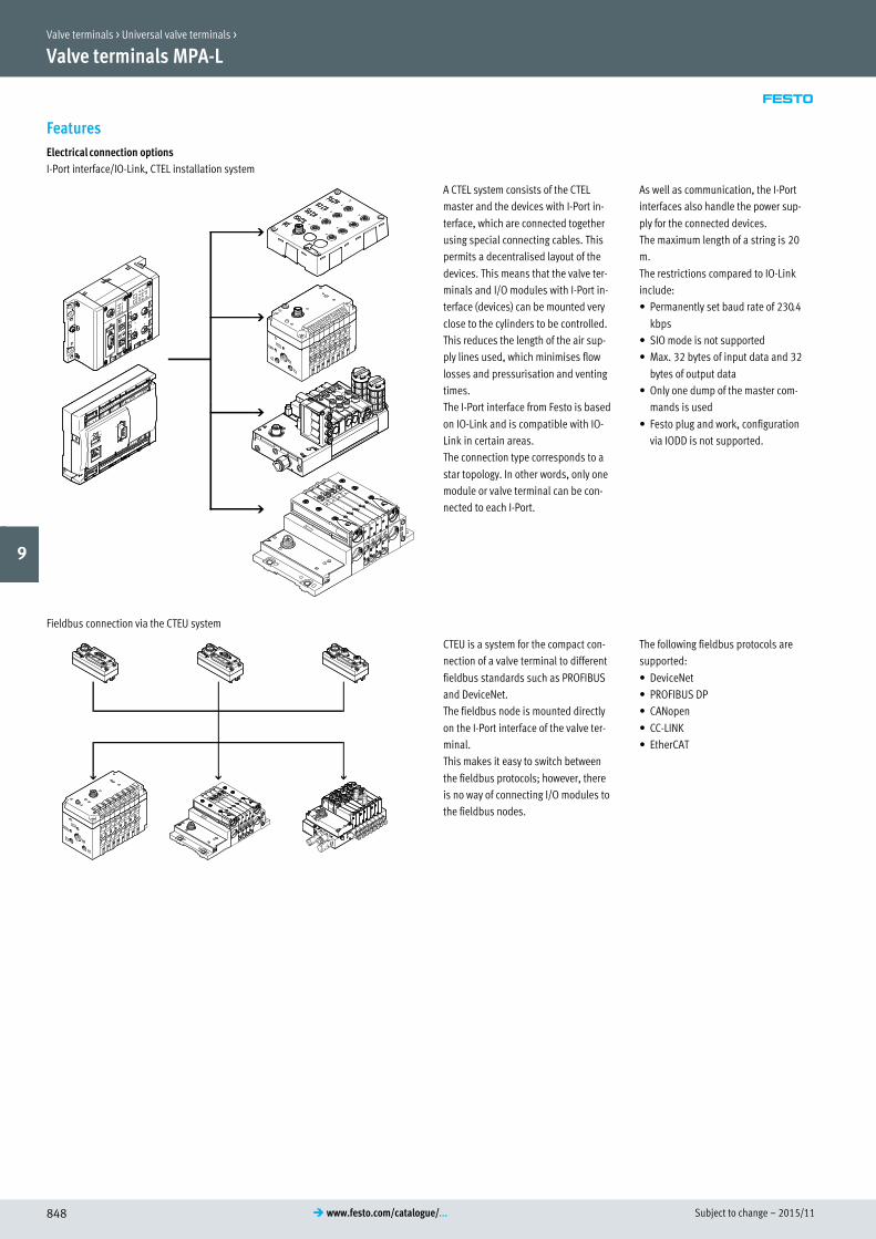
Subject to change – 2015/11848 � www.festo.com/catalogue/...
Valve terminals MPA-L
Features
Electrical connection options
I-Port interface/IO-Link, CTEL installation system
A CTEL system consists of the CTEL
master and the devices with I-Port in
terface, which are connected together
using special connecting cables. This
permits a decentralised layout of the
devices. This means that the valve ter
minals and I/O modules with I-Port in
terface (devices) can be mounted very
close to the cylinders to be controlled.
This reduces the length of the air sup
ply lines used, which minimises flow
losses and pressurisation and venting
times.
The I-Port interface from Festo is based
on IO-Link and is compatible with IO-
Link in certain areas.
The connection type corresponds to a
star topology. In other words, only one
module or valve terminal can be con
nected to each I-Port.
As well as communication, the I-Port
interfaces also handle the power sup
ply for the connected devices.
The maximum length of a string is 20
m.
The restrictions compared to IO-Link
include:
� Permanently set baud rate of 230.4
kbps
� SIO mode is not supported
� Max. 32 bytes of input data and 32
bytes of output data
� Only one dump of the master com
mands is used
� Festo plug and work, configuration
via IODD is not supported.
Fieldbus connection via the CTEU system
CTEU is a system for the compact con
nection of a valve terminal to different
fieldbus standards such as PROFIBUS
and DeviceNet.
The fieldbus node is mounted directly
on the I-Port interface of the valve ter
minal.
This makes it easy to switch between
the fieldbus protocols; however, there
is no way of connecting I/O modules to
the fieldbus nodes.
The following fieldbus protocols are
supported:
� DeviceNet
� PROFIBUS DP
� CANopen
� CC-LINK
� EtherCAT
Valve terminals > Universal valve terminals >
9

2015/11 – Subject to change 849� www.festo.com/catalogue/...
Valve terminals MPA-L
Data sheet
Valve terminal with multi-pin plug or fieldbus connection
-M- Flow rate
Up to 870 l/min
-K- Valve width
10 mm
14 mm
20 mm
-P- Operating voltage24 V DC
Technical data Download CAD data � www.festo.com
Max. number of valve positions 32
Max. number of pressure zones 9
Lubrication Life-time lubrication, PWIS-free (free of paint-wetting impairment substances)
Type of mounting Wall mounting
On H-rail to EN 60715
Manual override Non-detenting, detenting
Nominal voltage [V DC] 24
Operating conditions
Operating medium Compressed air to ISO 8573-1:2010 [7:4:4]
Note on operating/pilot medium Lubricated operation possible (in which case lubricated operation will always be
required)
Operating pressure [bar] –0.9 … +10
Pilot pressure [bar] 3 … 8
Ambient temperature [°C] –5 … +50
Current consumption per solenoid coil at nominal voltage
Width
10 mm 14 mm 20 mm
Nominal pick-up current [mA] 50 50 110
Nominal current with current reduction [mA] 10 10 23
Time until current reduction [ms] 20 20 20
Electrical data – MPA-L with electrical interface for CPX terminal
Intrinsic current consumption of valve terminal (internal electronics, without valves)
At 24 V UEL/SEN 1) [mA] Typically 13
At 24 V Uval 2) [mA] Typically 35
Diagnostic message
Undervoltage UOFF 3) [V] 17.7 … 17.8
1) Power supply for electronics and sensors.
2) Load voltage supply for valves.
3) Load voltage outside of function range.
Electrical data – MPA-L with I-Port interface/IO-Link
Intrinsic current consumption of valve terminal (internal electronics, without valves)
From operating voltage supply connection [mA] 30
From load voltage supply connection [mA] 30
Valve terminals > Universal valve terminals >
9

Subject to change – 2015/11850 � www.festo.com/catalogue/...
Valve terminals MPA-L
Data sheet
Technical data – Valve width 10 mm
Code for position function 1-32 M J N K H B G E X W D I
Switching times On [ms] 10 10 10 10 10 10 10 10 10 10 10 8
Off [ms] 20 – 20 20 20 35 35 35 20 20 20 20
Chan
ge-
over
[ms] – 15 – – – 15 15 15 – – – –
Operating pressure [bar] –0.9 … +10 3 … 10 –0.9 … +10 3 … 10
Standard nominal flow rate [l/min] 360 360 300 230 300 300 320 240 255 255 230 260
Design Piston spool valve
Materials Die-cast aluminium
Technical data – Valve width 10 mm
Code for position function 1-32 NS KS HS DS MU NU KU HU
Switching times On [ms] 14 14 14 14 10 8 8 8
Off [ms] 16 16 16 16 12 8 10 10
Chan
ge-
over
[ms] – – – – – – – –
Operating pressure [bar] –0.9 … +8 –0.9 … +10
Standard nominal flow rate [l/min] 300 230 300 230 190 190 160 190
Design Piston spool valve Poppet valve with spring return
Materials Die-cast aluminium Reinforced PPA
Technical data – Valve width 14 mm
Code for position function 1-32 M J N K H B G E X W D I NS KS HS DS
Switching times On [ms] 13 9 12 12 12 16 13 13 12 12 12 10 12 12 12 10
Off [ms] 30 – 38 38 38 50 52 50 20 20 30 28 23 23 23 25
Chan
ge-
over
[ms] – 24 – – – 26 26 26 – – – – – – – –
Operating pressure [bar] –0.9 … +10 3 … 10 –0.9 … +10 3 … 10 –0.9 … +10
Standard nominal flow rate [l/min] 670 670 650 600 650 630 610 480 400 400 650 670 520 560 520 570
Design Piston spool valve
Materials Die-cast aluminium
Technical data – Valve width 20 mm
Code for position function 1-32 M J N K H B G E X W D I NS KS HS DS
Switching times On [ms] 15 9 8 8 8 11 10 11 13 13 7 7 12 12 12 12
Off [ms] 28 – 28 28 28 46 40 47 22 22 25 23 25 25 25 25
Chan
ge-
over
[ms] – 22 – – – 23 21 23 – – – – – – – –
Operating pressure [bar] –0.9 … +10 3 … 10 –0.9 … +10 3 … 10 –0.9 … +8
Standard nominal flow rate [l/min] 700 860 610 550 550 550 750 700 480 480 840 680 620 500 550 820
Design Piston spool valve
Materials Die-cast aluminium
Valve terminals > Universal valve terminals >
9

2015/11 – Subject to change 851� www.festo.com/catalogue/...
Valve terminals MPA-L
Data sheet
Pneumatic ports
Right-hand end plate
Supply 1 Thread G1/4 (QS-G1/4, straight, for tubing O.D. 8 mm, 10 mm, 12 mm, 5/16", 3/8", 1/2")
Exhaust port 3
5
Pilot air supply 12/14 Thread M7 (QSM-M7, straight or angled, for tubing O.D. 4 mm, 6 mm, 1/4")
Pilot exhaust air 82/84
Supply module
Supply 1 Cartridge fitting 20 mm (QSPKG20, straight, for tubing O.D. 8 mm, 10 mm, 12 mm, 5/16", 3/8", 1/2", adapter to thread G1/4), flat
plate silencerExhaust port 3/5
Sub-base width 10 mm
Working ports 2 Cartridge fitting 10 mm (QSPKG10, straight or angled, for tubing O.D. 4 mm, 6 mm, 5/32", 1/4", adapter to thread M7)
4
Sub-base width 14 mm
Working ports 2 Cartridge fitting 14 mm (QSPKG14, straight or angled, for tubing O.D. 6 mm, 8 mm, 1/4", 5/16", adapter to thread G1/8)
4
Sub-base width 20 mm
Working ports 2 Cartridge fitting 18 mm (QSPKG18, straight or angled, for tubing O.D. 8 mm, 10 mm, 5/16", 3/8", adapter to thread G1/4)
4
Materials
Sub-base PA
Supply module PPA
End plate Die-cast aluminium, PA, PBT
Seals Nitrile rubber
Exhaust plate PA
Flat plate silencer PE
Electrical interlinking module PBT, PA, copper alloy
Valve terminals > Universal valve terminals >
9

Subject to change – 2015/11852 � www.festo.com/catalogue/...
Valve terminals MPA-L
Accessories
3
1
6
7
8
2
5
4
Accessories � Page/online
1 End plate VMPAL-EPL with multi-pin plug connection 849
2 Connecting cable VMPAL-KM for multi-pin plug connection 849
3 End plate with I-Port interface/IO-Link VMPAL-EPL-IPO32 849
4 Fieldbus node CTEU cteu
5 Connecting cable for I-Port interface/IO-Link NEBU-M12G5 854
6 End plate VMPAL-EPL-CPX with pneumatic interface for CPX terminal 849
7 Module CPX for CPX terminal 1185
8 Valve terminal, pneumatic part 849
Valve terminals > Universal valve terminals >
9

2015/11 – Subject to change 853� www.festo.com/catalogue/...
Valve terminals MPA-L
Accessories
aD
aI
aC
aG
bD
bC
9
aJ
aA
aB
aE
aF
bJ
bA
bB
9
aJ
aB
aC
aH
aH
bB
bB
Accessories � Page/online
9 Solenoid valve VMPA 849
aJ Cover VMPA-HB for manual override mpal
aA Vertical stacking modules VMPA1-B8/VMPA2-B8 mpal
aB Right-hand end plate VMPAL-EPR, with pilot air selector for choosing the pilot air supply (internal or external) mpal
aC Tie rod VMPAL-ZA mpal
aD Inscription label holder VMPAL-ST-AP 854
aE Inscription label IBS-6x10 854
aF Sub-base VMPAL-AP-4X, 4 pieces combined mpal
aG Sub-base VMPAL-AP mpal
aH Electrical interlinking module VMPAL-EVAP mpal
aI Supply module VMPAL-SP mpal
bJ Exhaust plate VMPA2-B8 mpal
bA Mounting VMPAL-BD 854
bB Cartridge fitting QSPKG 854
bC Fixed restrictor VMPA1-FT mpal
bD Electrical interlinking module VMPAL-EVAP-4 for four sub-bases mpal
Valve terminals > Universal valve terminals >
9
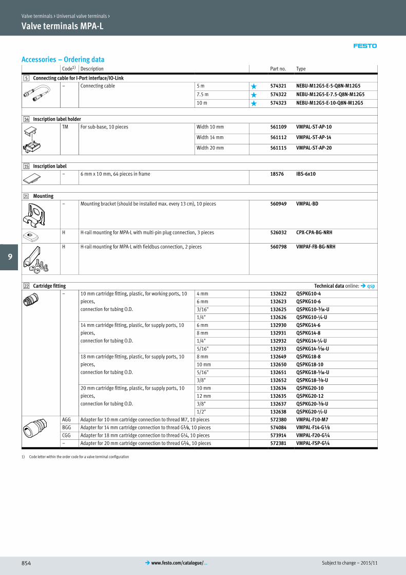
Subject to change – 2015/11854 � www.festo.com/catalogue/...
Valve terminals MPA-L
Accessories – Ordering dataCode1) Description Part no. Type
5 Connecting cable for I-Port interface/IO-Link
– Connecting cable 5 m 574321 NEBU-M12G5-E-5-Q8N-M12G5
7.5 m 574322 NEBU-M12G5-E-7.5-Q8N-M12G5
10 m 574323 NEBU-M12G5-E-10-Q8N-M12G5
aD Inscription label holder
TM For sub-base, 10 pieces Width 10 mm 561109 VMPAL-ST-AP-10
Width 14 mm 561112 VMPAL-ST-AP-14
Width 20 mm 561115 VMPAL-ST-AP-20
aE Inscription label
– 6 mm x 10 mm, 64 pieces in frame 18576 IBS-6x10
bA Mounting
– Mounting bracket (should be installed max. every 13 cm), 10 pieces 560949 VMPAL-BD
H H-rail mounting for MPA-L with multi-pin plug connection, 3 pieces 526032 CPX-CPA-BG-NRH
H H-rail mounting for MPA-L with fieldbus connection, 2 pieces 560798 VMPAF-FB-BG-NRH
bB Cartridge fitting Technical data online: � qsp
– 10 mm cartridge fitting, plastic, for working ports, 10
pieces,
connection for tubing O.D.
4 mm 132622 QSPKG10-4
6 mm 132623 QSPKG10-6
3/16" 132625 QSPKG10-Ã-U
1/4" 132626 QSPKG10-¼-U
14 mm cartridge fitting, plastic, for supply ports, 10
pieces,
connection for tubing O.D.
6 mm 132930 QSPKG14-6
8 mm 132931 QSPKG14-8
1/4" 132932 QSPKG14-¼-U
5/16" 132933 QSPKG14-Ä-U
18 mm cartridge fitting, plastic, for supply ports, 10
pieces,
connection for tubing O.D.
8 mm 132649 QSPKG18-8
10 mm 132650 QSPKG18-10
5/16" 132651 QSPKG18-Ä-U
3/8" 132652 QSPKG18-Å-U
20 mm cartridge fitting, plastic, for supply ports, 10
pieces,
connection for tubing O.D.
10 mm 132634 QSPKG20-10
12 mm 132635 QSPKG20-12
3/8" 132637 QSPKG20-Å-U
1/2" 132638 QSPKG20-½-U
AGG Adapter for 10 mm cartridge connection to thread M7, 10 pieces 572380 VMPAL-F10-M7
BGG Adapter for 14 mm cartridge connection to thread Gx, 10 pieces 574084 VMPAL-F14-GÁ
CGG Adapter for 18 mm cartridge connection to thread G¼, 10 pieces 573914 VMPAL-F20-G¼
– Adapter for 20 mm cartridge connection to thread G¼, 10 pieces 572381 VMPAL-FSP-G¼
1) Code letter within the order code for a valve terminal configuration
Valve terminals > Universal valve terminals >
9