Embed Size (px)
Citation preview

Spearhead Multicut 620
1111
MULTICUT 620
9th
Edition – August 2016
Part No. 8999024
Spearhead Multicut 620
2222
Spearhead
MULTICUT MULTICUT MULTICUT MULTICUT 620620620620
HandbookHandbookHandbookHandbook
9th Edition – August 2016
Important Note The information contained in this manual is correct at the time of publication.
However, in the course of constant development, changes in specification are Inevitable. Should you find the information given in this book different to the Machine it relates to please contact the “After Sales Department” for advice.
© Spearhead Machinery Limited 2004
Please ensure that this manual is handed to the operator before using the machine for the first time. The operator must fully understand the contents
of this manual before using this machine. (If the machine is resold the Manual must be given to the new owner.)
Spearhead Machinery Green View
Salford Priors Evesham
Worcestershire WR11 8SW
Tel: 01789 491860 Fax: 01789 778683
www.spearheadmachinery.com [email protected]
Spearhead Multicut 620
3333
IMPORTANT VERIFICATION OF WARRANTY REGISTRATION
DEALER WARRANTY INFORMATION & REGISTRATION VERIFICATION It is imperative that the selling dealer registers this machine with Spearhead Machinery Limited before delivery to the end user – failure to do so may affect the validity of the machine warranty. To register machines go to the Spearhead Machinery Limited web site at www.spearheadmachinery.com , log onto ‘Dealer Inside ’ and select the ‘Machine Registration button ’ which can be found in the Service Section of the site. Confirm to the customer that the machine has been registered in the section below.
Should you experience any problems registering a ma chine in this manner please contact the Spearhead Service Department on 01789 4 91867.
Registration Verification
NOTE TO CUSTOMER / OWNER Please ensure that the above section has been compl eted and signed by the selling dealer to verify that your machine has been registe red with Spearhead Machinery
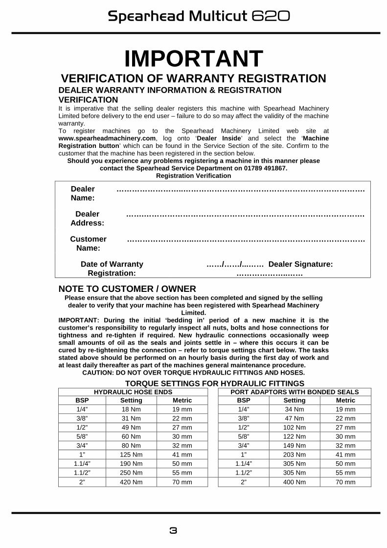
Limited. IMPORTANT: During the initial ‘bedding in’ period o f a new machine it is the customer’s responsibility to regularly inspect all nuts, bolts and hose connections for tightness and re-tighten if required. New hydraulic connections occasionally weep small amounts of oil as the seals and joints settle in – where this occurs it can be cured by re-tightening the connection – refer to torque settings chart below. The tasks stated above should be performed on an hourly basis during the first day of work and at least daily thereafter as part of the machines g eneral maintenance procedure.
CAUTION: DO NOT OVER TORQUE HYDRAULIC FITTINGS AND HOSES.
TORQUE SETTINGS FOR HYDRAULIC FITTINGS HYDRAULIC HOSE ENDS PORT ADAPTORS WITH BONDED SEALS
BSP Setting Metric BSP Setting Metric 1/4” 18 Nm 19 mm 1/4” 34 Nm 19 mm 3/8” 31 Nm 22 mm 3/8” 47 Nm 22 mm 1/2” 49 Nm 27 mm 1/2” 102 Nm 27 mm 5/8” 60 Nm 30 mm 5/8” 122 Nm 30 mm 3/4” 80 Nm 32 mm 3/4” 149 Nm 32 mm 1” 125 Nm 41 mm 1” 203 Nm 41 mm
1.1/4” 190 Nm 50 mm 1.1/4” 305 Nm 50 mm 1.1/2” 250 Nm 55 mm 1.1/2” 305 Nm 55 mm
2” 420 Nm 70 mm 2” 400 Nm 70 mm
Dealer Name:
……………………..…………………………………………………………….
Dealer Address:
…….………………………………………………………………………….
Customer Name:
……………………..…………………………………………………………
Date of Warranty Registration:
……/……/...…… Dealer Signature: ………………..……
Spearhead Multicut 620
4444
WARRANTY POLICY
WARRANTY REGISTRATION
All machines must be registered, by the selling dea ler with Spearhead Machinery Ltd, before delivery to the end user. On receipt of the goods it is the buyer’s responsibility to check that the Verification of Warranty Registration in the Operato r’s Manual has been completed by the selling
dealer. 1. LIMITED WARRANTIES
1.01. All machines supplied by Spearhead Machinery Limited are warranted to be free from defects in
material and workmanship from the date of sale to the original purchaser for a period of 12 months, unless a different period is specified.
1.02. All spare parts supplied by Spearhead Machinery Limited are warranted to be free from defects in material and workmanship from the date of sale to the original purchaser for a period of 6 months.
1.03. The manufacturer will replace or repair for the purchaser any part or parts found, upon
examination at its factory, to be defective under normal use and service due to defects in material or workmanship. Returned parts must be complete and unexamined.
1.04. This warranty does not apply to any part of the goods, which has been subjected to improper or
abnormal use, negligence, alteration, modification, fitment of non-genuine parts, accident damage, or damage resulting from contact with overhead power lines, damage caused by foreign objects (e.g. stones, iron, material other than vegetation), failure due to lack of maintenance, use of incorrect oil or lubricants, contamination of the oil, or which has served its normal life. This warranty does not apply to any expendable items such as blades, flails, bushes, belts, flap kits, skids, shields, guards, wear pads or pneumatic tyres.
1.05. Temporary repairs and consequential loss - i.e. oil, downtime and associated parts are
specifically excluded from the warranty. 1.06. Warranty on hoses is limited to 12 months and does not include hoses which have suffered
external damage. Only complete hoses may be returned under warranty, any which have been cut or repaired will be rejected.
1.07. Machines must be repaired immediately a problem arises. Continued use of the machine after a
problem has occurred can result in further component failures, for which Spearhead Machinery Ltd cannot be held liable, and may have safety implications.
1.08. Except as provided herein, no employee, agent, dealer or other person is authorised to give any
warranties of any nature on behalf of Spearhead Machinery Ltd. 1.09. For machine warranty periods in excess of 12 months the following additional exclusions shall
apply:
1.09.1. Hoses, external seals, exposed pipes and hydraulic tank breathers. 1.09.2. Filters 1.09.3. Rubber mountings 1.09.4. External electric wiring. 1.09.5. Labour and mileage costs.
1.10. All service work, particularly filter changes, must be carried out in accordance with the
manufacturer’s service schedule. Failure to comply will invalidate the warranty. In the event of a claim, proof of the service work being carried out may be required.
NB Warranty cover will be invalid if any non-genuin e parts have been fitted or used. Use of non-genuine parts may seriously affect the m achine’s performance and safety.
Spearhead Machinery Ltd cannot be held responsible for any failures or safety implications that arise due to the use of non-genui ne parts.
Spearhead Multicut 620
5555
2. REMEDIES AND PROCEDURES
2.01. The warranty is not effective unless the Selling Dealer registers the machine, via the Spearhead Machinery web site and confirms the registration to the purchaser by completing the confirmation form in the operator’s manual.
2.02. Any fault must be reported to an authorised Spearhead Machinery dealer as soon as it occurs. Continued use of a machine, after a fault has occurred, can result in further component failure for which Spearhead Machinery Ltd cannot be held liable.
2.03. Repairs should be undertaken within two days of the failure. Claims submitted for repairs
undertaken more than 2 weeks after a failure has occurred, or 2 days after the parts were supplied will be rejected, unless the delay has been authorised by Spearhead Machinery Ltd.
2.04. All claims must be submitted, by an authorised Spearhead Machinery Service Dealer, within 30
days of the date of repair. 2.05. Following examination of the claim and parts the manufacturer will pay, at their discretion, for any
valid claim the cost of any parts and an appropriate labour allowance if applicable. 2.06. The submission of a claim is not a guarantee of payment. 2.07. Any decision reached by Spearhead Machinery Ltd is final.
3. LIMITATION OF LIABILITY
3.01. The manufacturer disclaims any express (except as set forth herein) and implied warranties with
respect to the goods including, but not limited to, merchantability and fitness for a particular purpose.
3.02. The manufacturer makes no warranty as to the design, capability, capacity or suitability for use of the goods.
3.03. Except as provided herein, the manufacturer shall have no liability or responsibility to the
purchaser or any other person or entity with respect to any liability, loss, or damage caused or alleged to be caused directly or indirectly by the goods including, but not limited to, any indirect, special, consequential, or incidental damages resulting from the use or operation of the goods or any breach of this warranty. Notwithstanding the above limitations and warranties, the manufacturer’s liability hereunder for damages incurred by the purchaser or others shall not exceed the price of the goods.
3.04. No action arising out of any claimed breach of this warranty or transactions under this warranty
may be brought more than one (1) year after the cause of the action has occurred.
4. MISCELLANEOUS
4.01. The manufacturer may waive compliance with any of the terms of this limited warranty, but no
waiver of any terms shall be deemed to be a waiver of any other term.
4.02. If any provision of this limited warranty shall violate any applicable law and is held to be unenforceable, then the invalidity of such provision shall not invalidate any other provisions herein.
4.03. Applicable law may provide rights and benefits to the purchaser in addition to those provided
herein.
Spearhead Multicut 620
6666
CCCCEEEE Declaration of Conformity,Declaration of Conformity,Declaration of Conformity,Declaration of Conformity, Conforming to EConforming to EConforming to EConforming to EUUUU Machinery Machinery Machinery Machinery Directive Directive Directive Directive
2006/422006/422006/422006/42////ECECECEC
We, Spearhead Machinery Ltd, Green View, Salford Priors, Evesham, Worcestershire, WR11 8SW hereby declare that:
Product Product Product Product ……………………………………………..…………………………
Product CodeProduct CodeProduct CodeProduct Code……………………………………………..…………………………
Serial NoSerial NoSerial NoSerial No……………………………………………..……..………………….
TypeTypeTypeType……………………………………………..…………………………
Manufactured by: Alamo Manufacturing Services (UK) Limited, Station
Road, Salford Priors, Evesham, Worcestershire, WR11 8SW
Complies with the required provisions of the Machinery Directive 2006/42/EC. The Machinery Directive is supported by the following
harmonized standards:
• BS EN ISO 14121-1 (2007) Safety of Machinery – Risk Assessment, Part 1: Principles Part 2: Practical Guide and Examples of Methods.
• BS EN ISO 12100-1 (2010) Safety of Machinery – Part 1: Basic Terminology and Methodology Part 2: Technical Principles.
• BS EN 349 (1993) + A1 (2008) Safety of Machinery – Minimum Distances to avoid the Entrapment of Human Body Parts.
• BS EN 953 (1998) Safety of Machinery – Guards General Requirements for the Design and Construction of Fixed and Movable Guards.
• BS EN 982 (1996) + A1 (2008) Safety Requirements for Fluid Power Systems and their Components. Hydraulics.
The EC Declaration only applies if the machine stated above is used in
accordance with the operating instructions. SignedSignedSignedSigned
(On beOn beOn beOn behalf of Spearhead Machinery Ltdhalf of Spearhead Machinery Ltdhalf of Spearhead Machinery Ltdhalf of Spearhead Machinery Ltd)
StatusStatusStatusStatus General Manager DateDateDateDate ………………………………………………
Spearhead Multicut 620
7777
ContentsContentsContentsContents Warranty 3
Contents 7
Safety 8
Recommendations 9
Introduction 11
Tractor Requirements 11
Attaching To The Tractor 11
Setting Up Your Machine 14
Operation 18
Transportation 20
Machine Protection 21
Servicing & MaintenanceServicing & MaintenanceServicing & MaintenanceServicing & Maintenance Safety First 22
Daily 23
Every 8 Hours 24
Torque Settings 24
Regularly 25
Blades 25
Slip Clutch Settings 26
Skids 27
Wheels 27
Storage 28
Trouble Shooting Guide 29

Spearhead Multicut 620
8888
SafetySafetySafetySafety
Warning Avoid fluid escaping under pressure. Consult technical manual for services procedures.
Warning Danger – flying objects keep safe distance from the machine as long as the engine is running.
Warning Stay clear of mower blade as long as engine is running.
Warning Stay clear of swinging area of implements.
Warning Shut off engine and remove key before performing maintenance or repair work.
Warning Check all nuts are tight every 8 hours.
Warning Carefully read operator’s manual before handling this machine. Observe instructions and safety rules when operating.
Spearhead Multicut 620
9999
RecommendationsRecommendationsRecommendationsRecommendations Beware of the following Potential Dangers associate d with the use of this machine:
• Becoming trapped when hitching or unhitching • Machine overbalancing when wing is raised. • Getting caught on rotating power take off (PTO) • Being hit or caught by any moving part, e.g. Blades, drive shaft and wings. • Being hit by flying debris or machine parts due to machine damage • Machine overbalancing when not in use • Injection of high pressure oil from damaged couplings or hydraulic hoses • Accidents due to collision with other machines, or debris left on road • Beware of free-swinging blades over centering and falling when wings are
folding. ALWAYS:ALWAYS:ALWAYS:ALWAYS:
• Ensure the operator has read this handbook and has been trained to use the machine.
• Ensure all safety guards are in place and all tractor windows closed. • Impact resistant shielding to the tractor is recommended • Before leaving the tractor cab always ensure that the wings are firmly on the
ground, no weight is on the machine’s hydraulics and the rotor has stopped spinning.
• Check that all guards are properly fitted and there are no damaged or loose parts. Particular attention should be given to the blades to ensure they are not damaged, cracked or missing
• Inspect work area for wire, steel posts, large stones and other dangerous materials and remove before starting work.
• Ensure that all warning labels are always visible and that they are not damaged, defaced or missing.
• Fit locking pins to height and to wings before transport and before unhitching when applicable.
• Wear ear defenders if operating without a quiet cab or with the cab windows open
• Ensure tractor guards are fitted correctly and are undamaged • Work at a safe speed, taking into account terrain, passing vehicles and
obstacles • Ensure that the tractor meets the minimum weight recommendations of the
machine manufacturer and that ballast is used if necessary • Check that machine fittings and couplings are in good condition • Follow the manufacturer’s instructions for attachment and removal of machine
from the tractor • Ensure blades are of the type recommended by the manufacturer, are
securely fitted and are undamaged • Ensure hydraulic pipes are correctly routed to avoid damage from chafing,
stretching, pinching or kinking. • Check condition of tyres and tightness of wheel nuts.
Spearhead Multicut 620
10101010
RecommendationsRecommendationsRecommendationsRecommendations
• Ensure all blades have stopped spinning before folding wings into transport position.
• Disengage the machine, stop the engine and remove the key before leaving the tractor cab for any reason
• Clean up any debris left at the work site. • Ensure that when you remove the machine from the tractor it is secured in a
safe position using the stands provided. NEVER:NEVER:NEVER:NEVER: • Never operate the machine with other people present, as it is possible for
debris, including stones, to be discharged from the front and rear. • Never operate the machine until you have read and understood this
Handbook and are familiar with the controls. • Never use a machine that is poorly maintained or has guards that are
damaged or missing • Never allow an inexperienced person to operate the machine without
supervision. • Never use or fit a machine onto a tractor if it doesn’t meet the manufacturer’s
specification. • Never use a machine if the hydraulic system shows signs of damage. • Never attempt to detect a hydraulic leak with your hand, use a piece of card. • Never allow children to play on or around the machine at any time. • Never attempt any maintenance or adjustment without first disengaging the
PTO, lowering the wings to the ground, stopping the tractor engine and applying the tractor parking brake.
• Never leave the cab without removing the ignition key. • Never operate the tractor or any controls from any position other than from
the driving seat. • Never stop the engine with the PTO engaged. • Never operate with blades missing. • Never operate PTO above recommended speed, 1000 r.p.m. • Never operate with wire around the rotor. Stop immediately. • Never use the wing raised which may throw debris towards the cab. • Never attempt to use the machine for any purpose other than that it was
designed for. • Never transport with the PTO engaged. • Never enter the working area of the machine (risk of injury!). • Never engage the P.T.O with wings folded.
Spearhead Multicut 620
11111111
IntroductionIntroductionIntroductionIntroduction The Spearhead 620 is a heavy-duty rotary mower for a set-aside, stubble and pasture topping. By carefully following the instructions in this handbook, the 620 will give many years of trouble free operation. Safety First Safety First Safety First Safety First Never start using the machine until the handbook has been read and understood. The 620 rotary mower is a potentially lethal machine if used incorrectly and it is essential that the operator fully understand the working before starting up. Tractor RequirementsTractor RequirementsTractor RequirementsTractor Requirements
• Spearhead recommend tractors of between 85 and 150hp. • A clevis drawbar must be used, • The tractor should have a minimum weight of 3000 kg. • The tractor should have a 1,000rpm P.T.O. • Two external hydraulic services are required, single acting for height control
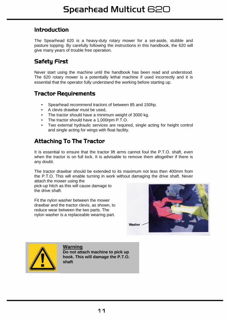
and single acting for wings with float facility. Attaching To The TractorAttaching To The TractorAttaching To The TractorAttaching To The Tractor It is essential to ensure that the tractor lift arms cannot foul the P.T.O. shaft, even when the tractor is on full lock. It is advisable to remove them altogether if there is any doubt. The tractor drawbar should be extended to its maximum not less then 400mm from the P.T.O. This will enable turning in work without damaging the drive shaft. Never attach the mower using the pick-up hitch as this will cause damage to the drive shaft. Fit the nylon washer between the mower drawbar and the tractor clevis, as shown, to reduce wear between the two parts. The nylon washer is a replaceable wearing part.
Warning Do not attach machine to pick up hook. This will damage the P.T.O. shaft
Spearhead Multicut 620
12121212
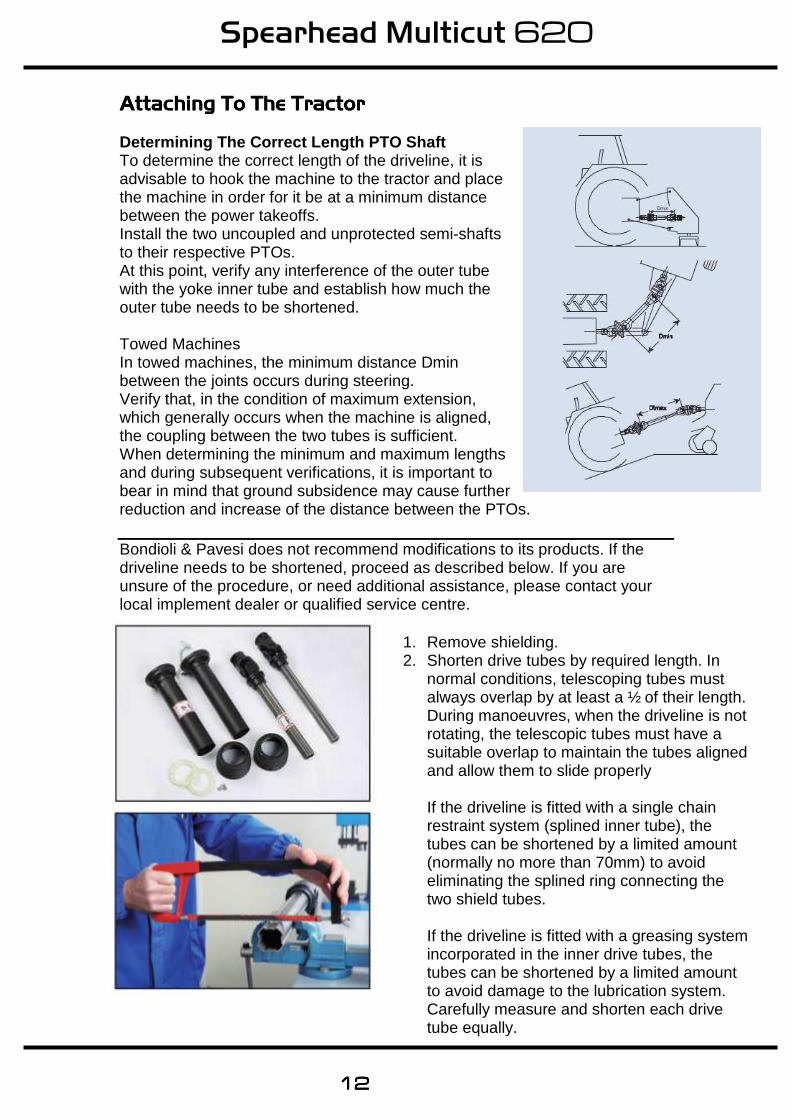
Attaching To The TractorAttaching To The TractorAttaching To The TractorAttaching To The Tractor Determining The Correct Length PTO Shaft To determine the correct length of the driveline, it is advisable to hook the machine to the tractor and place the machine in order for it be at a minimum distance between the power takeoffs. Install the two uncoupled and unprotected semi-shafts to their respective PTOs. At this point, verify any interference of the outer tube with the yoke inner tube and establish how much the outer tube needs to be shortened. Towed Machines In towed machines, the minimum distance Dmin between the joints occurs during steering. Verify that, in the condition of maximum extension, which generally occurs when the machine is aligned, the coupling between the two tubes is sufficient. When determining the minimum and maximum lengths and during subsequent verifications, it is important to bear in mind that ground subsidence may cause further reduction and increase of the distance between the PTOs. Bondioli & Pavesi does not recommend modifications to its products. If the driveline needs to be shortened, proceed as described below. If you are unsure of the procedure, or need additional assistance, please contact your local implement dealer or qualified service centre.
1. Remove shielding. 2. Shorten drive tubes by required length. In
normal conditions, telescoping tubes must always overlap by at least a ½ of their length. During manoeuvres, when the driveline is not rotating, the telescopic tubes must have a suitable overlap to maintain the tubes aligned and allow them to slide properly If the driveline is fitted with a single chain restraint system (splined inner tube), the tubes can be shortened by a limited amount (normally no more than 70mm) to avoid eliminating the splined ring connecting the two shield tubes. If the driveline is fitted with a greasing system incorporated in the inner drive tubes, the tubes can be shortened by a limited amount to avoid damage to the lubrication system. Carefully measure and shorten each drive tube equally.
Spearhead Multicut 620
13131313
Before fitting the PTO for the first time, it may be necessary to adjust the length. There should be maximum engagement of the sliding tubes without bottoming at the shortest operation position. To check, first connect the mower to the tractor. Pull the PTO shaft apart and connect to the tractor
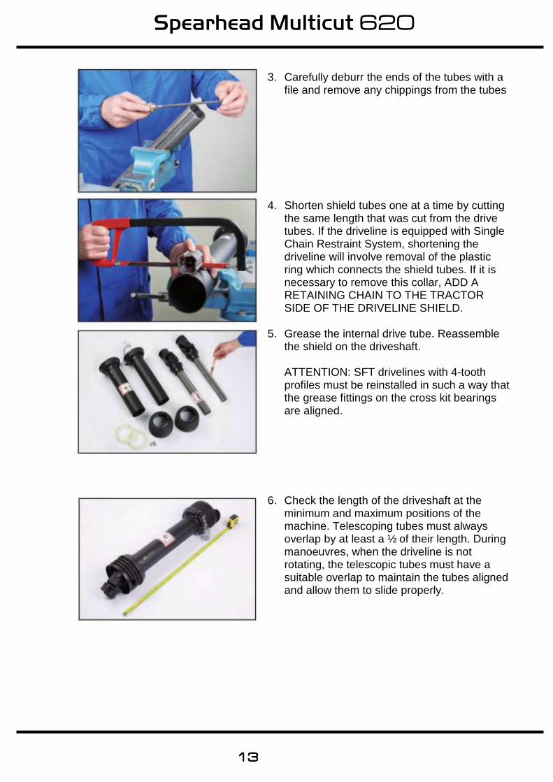
3. Carefully deburr the ends of the tubes with a file and remove any chippings from the tubes
4. Shorten shield tubes one at a time by cutting the same length that was cut from the drive tubes. If the driveline is equipped with Single Chain Restraint System, shortening the driveline will involve removal of the plastic ring which connects the shield tubes. If it is necessary to remove this collar, ADD A RETAINING CHAIN TO THE TRACTOR SIDE OF THE DRIVELINE SHIELD.
5. Grease the internal drive tube. Reassemble the shield on the driveshaft. ATTENTION: SFT drivelines with 4-tooth profiles must be reinstalled in such a way that the grease fittings on the cross kit bearings are aligned.
6. Check the length of the driveshaft at the minimum and maximum positions of the machine. Telescoping tubes must always overlap by at least a ½ of their length. During manoeuvres, when the driveline is not rotating, the telescopic tubes must have a suitable overlap to maintain the tubes aligned and allow them to slide properly.
Spearhead Multicut 620
14141414
Setting Up Your Machine Setting Up Your Machine Setting Up Your Machine Setting Up Your Machine Levelling Levelling Levelling Levelling –––– Front To RearFront To RearFront To RearFront To Rear
Once coupled to the tractor, check the mower is cutting level from the front to the rear of the machine. This is important to ensure each rotor will cut at the same height.
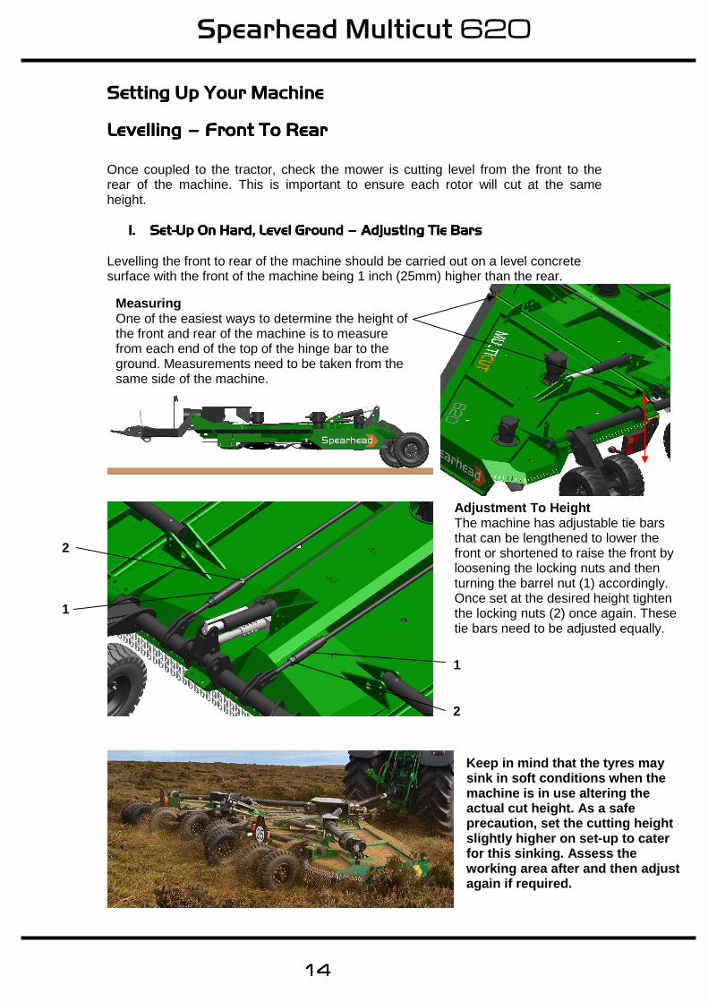
1.1.1.1. SetSetSetSet----Up On Hard, Level GroundUp On Hard, Level GroundUp On Hard, Level GroundUp On Hard, Level Ground –––– Adjusting Tie BarsAdjusting Tie BarsAdjusting Tie BarsAdjusting Tie Bars Levelling the front to rear of the machine should be carried out on a level concrete surface with the front of the machine being 1 inch (25mm) higher than the rear.
Keep in mind that the tyres may sink in soft conditions when the machine is in use altering the actual cut height. As a safe precaution, set the cutting height slightly higher on set-up to cater for this sinking. Assess the working area after and then adjust again if required.
1
1
2
2
Adjustment To Height The machine has adjustable tie bars that can be lengthened to lower the front or shortened to raise the front by loosening the locking nuts and then turning the barrel nut (1) accordingly. Once set at the desired height tighten the locking nuts (2) once again. These tie bars need to be adjusted equally.
Measuring One of the easiest ways to determine the height of the front and rear of the machine is to measure from each end of the top of the hinge bar to the ground. Measurements need to be taken from the same side of the machine.
Spearhead Multicut 620
15151515
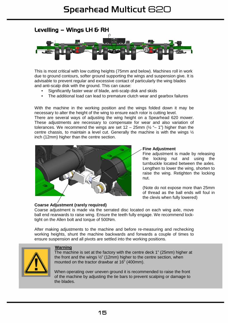
Levelling Levelling Levelling Levelling –––– Wings LH & RHWings LH & RHWings LH & RHWings LH & RH
This is most critical with low cutting heights (75mm and below). Machines roll in work due to ground contours, softer ground supporting the wings and suspension give. It is advisable to prevent regular and excessive contact of particularly the wing blades and anti-scalp disk with the ground. This can cause:
• Significantly faster wear of blade, anti-scalp disk and skids • The additional load can lead to premature clutch wear and gearbox failures
With the machine in the working position and the wings folded down it may be necessary to alter the height of the wing to ensure each rotor is cutting level. There are several ways of adjusting the wing height on a Spearhead 620 mower. These adjustments are necessary to compensate for wear and also variation of tolerances. We recommend the wings are set 12 – 25mm (½ “– 1”) higher than the centre chassis, to maintain a level cut. Generally the machine is with the wings ½ inch (12mm) higher than the centre section.
Coarse Adjustment (rarely required) Coarse adjustment is made via the serrated disc located on each wing axle, move ball end rearwards to raise wing. Ensure the teeth fully engage. We recommend lock-tight on the Allen bolt and torque of 500Nm. After making adjustments to the machine and before re-measuring and rechecking working heights, shunt the machine backwards and forwards a couple of times to ensure suspension and all pivots are settled into the working positions.
Setting Up Your Machine
Warning The machine is set at the factory with the centre deck 1” (25mm) higher at the front and the wings ½” (12mm) higher to the centre section, when mounted on the tractor drawbar at 16” (400mm). When operating over uneven ground it is recommended to raise the front of the machine by adjusting the tie bars to prevent scalping or damage to the blades.
Fine Adjustment Fine adjustment is made by releasing the locking nut and using the turnbuckle located between the axles. Lengthen to lower the wing, shorten to raise the wing. Retighten the locking nut.
(Note do not expose more than 25mm of thread as the ball ends will foul in the clevis when fully lowered)
Spearhead Multicut 620
16161616
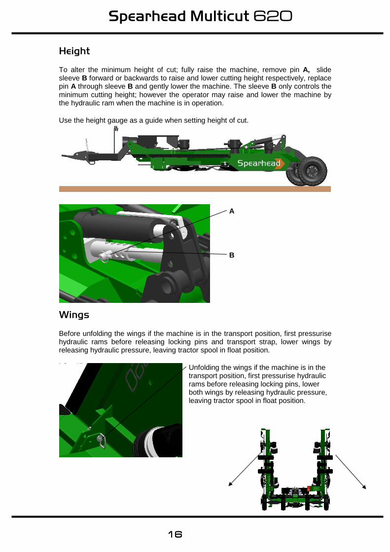
Height To alter the minimum height of cut; fully raise the machine, remove pin A, slide sleeve B forward or backwards to raise and lower cutting height respectively, replace pin A through sleeve B and gently lower the machine. The sleeve B only controls the minimum cutting height; however the operator may raise and lower the machine by the hydraulic ram when the machine is in operation. Use the height gauge as a guide when setting height of cut.
Wings Before unfolding the wings if the machine is in the transport position, first pressurise hydraulic rams before releasing locking pins and transport strap, lower wings by releasing hydraulic pressure, leaving tractor spool in float position.
Unfolding the wings if the machine is in the transport position, first pressurise hydraulic rams before releasing locking pins, lower both wings by releasing hydraulic pressure, leaving tractor spool in float position.
A
B
Spearhead Multicut 620
17171717
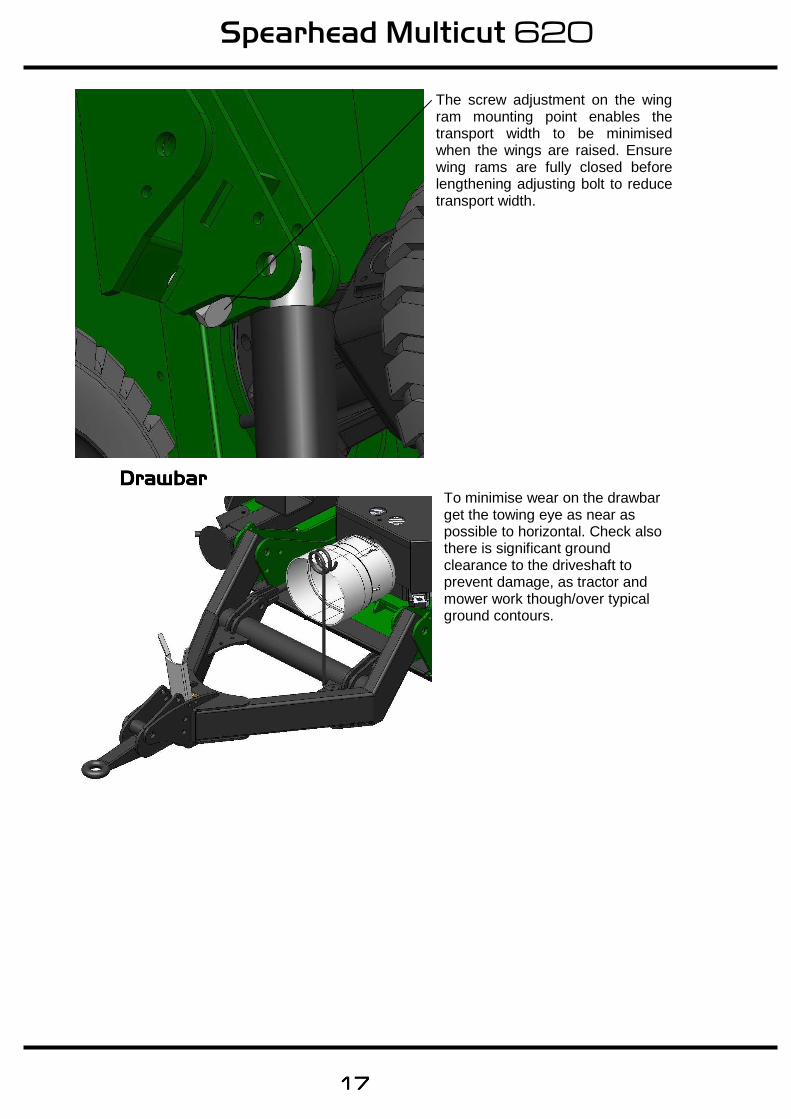
The screw adjustment on the wing ram mounting point enables the transport width to be minimised when the wings are raised. Ensure wing rams are fully closed before lengthening adjusting bolt to reduce transport width.
DrawbarDrawbarDrawbarDrawbar To minimise wear on the drawbar get the towing eye as near as possible to horizontal. Check also there is significant ground clearance to the driveshaft to prevent damage, as tractor and mower work though/over typical ground contours.
Spearhead Multicut 620
18181818
OperationOperationOperationOperation
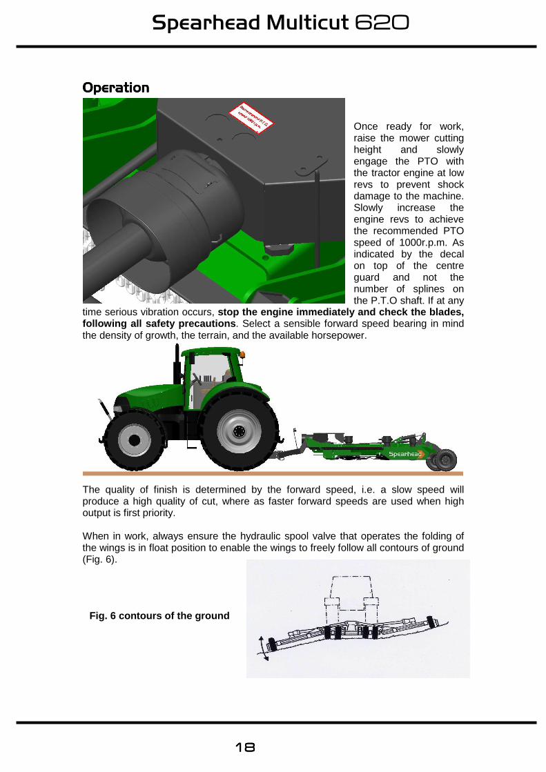
Once ready for work, raise the mower cutting height and slowly engage the PTO with the tractor engine at low revs to prevent shock damage to the machine. Slowly increase the engine revs to achieve the recommended PTO speed of 1000r.p.m. As indicated by the decal on top of the centre guard and not the number of splines on the P.T.O shaft. If at any
time serious vibration occurs, stop the engine immediately and check the blades, following all safety precautions . Select a sensible forward speed bearing in mind the density of growth, the terrain, and the available horsepower.
The quality of finish is determined by the forward speed, i.e. a slow speed will produce a high quality of cut, where as faster forward speeds are used when high output is first priority. When in work, always ensure the hydraulic spool valve that operates the folding of the wings is in float position to enable the wings to freely follow all contours of ground (Fig. 6).
Fig. 6 contours of the ground
Spearhead Multicut 620
19191919
RecommendedRecommendedRecommendedRecommended Do not operate the machine over rough terrain on the height stop, as any shock loads may cause stress leading to fatigue and failures. Carry the weight on the gas suspension system by removing the height stop pin. Whilst operating it is possible to continue working when turning as the 620 Rotary Cutter is fitted with a constant velocity joint on PTO shaft. However take care not to run the rear tractor wheel against the mower draw bar as this will result in serious damage to the tractor, the mower and, in particular, the PTO shaft. The wide angle joint on the input PTO shaft, allows the PTO to be left in gear whilst turning out of work, e.g. on the headlands. It is important not to turn sharply when the machine is in work as this will over-strain and shorten the life of the drive shaft. When operating in confined areas it is possible to cut going backwards, but it is advisable to slightly raise the machine, particularly if in scrub, where there is the risk of hitting hidden solid obstacles obscured by dense undergrowth. Always exercise particular care when operating over uneven ground surfaces. Do not allow the blades and blade holder to frequently hit the ground. Do not allow debris to build upon the cutting decks in dry conditions, as this can be a fire hazard, in wet conditions it will place unnecessary strain on the machine and may foul the drive shaft causing damage. OptionsOptionsOptionsOptions
• A swivel drawbar hitch is available if the machine is to be used in a very uneven condition.
• Wide Wheel for larger ground and lower pressure footprint for use on softer ground surfaces
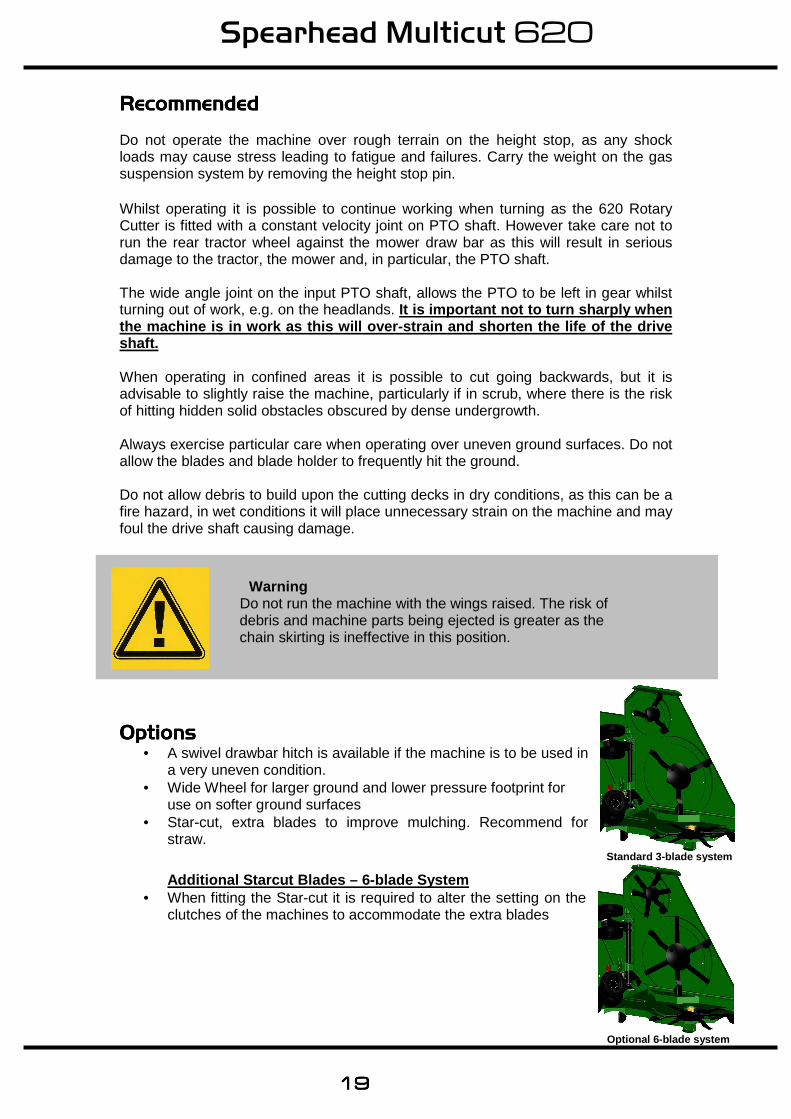
• Star-cut, extra blades to improve mulching. Recommend for straw.
Additional Starcut Blades – 6-blade System
• When fitting the Star-cut it is required to alter the setting on the clutches of the machines to accommodate the extra blades
Warning Do not run the machine with the wings raised. The risk of debris and machine parts being ejected is greater as the chain skirting is ineffective in this position.
Optional 6 -blade system
Standard 3 -blade system
Spearhead Multicut 620
20202020
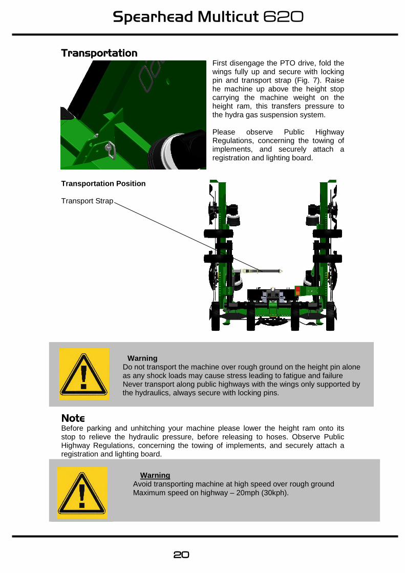
TransportationTransportationTransportationTransportation First disengage the PTO drive, fold the wings fully up and secure with locking pin and transport strap (Fig. 7). Raise he machine up above the height stop carrying the machine weight on the height ram, this transfers pressure to the hydra gas suspension system. Please observe Public Highway Regulations, concerning the towing of implements, and securely attach a registration and lighting board.
Transportation Position Transport Strap
NoteNoteNoteNote Before parking and unhitching your machine please lower the height ram onto its stop to relieve the hydraulic pressure, before releasing to hoses. Observe Public Highway Regulations, concerning the towing of implements, and securely attach a registration and lighting board.
Warning Avoid transporting machine at high speed over rough ground Maximum speed on highway – 20mph (30kph).
Warning Do not transport the machine over rough ground on the height pin alone as any shock loads may cause stress leading to fatigue and failure Never transport along public highways with the wings only supported by the hydraulics, always secure with locking pins.
Spearhead Multicut 620
21212121
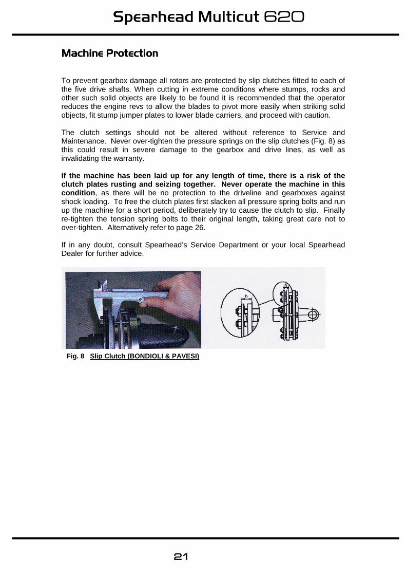
Machine ProtectionMachine ProtectionMachine ProtectionMachine Protection To prevent gearbox damage all rotors are protected by slip clutches fitted to each of the five drive shafts. When cutting in extreme conditions where stumps, rocks and other such solid objects are likely to be found it is recommended that the operator reduces the engine revs to allow the blades to pivot more easily when striking solid objects, fit stump jumper plates to lower blade carriers, and proceed with caution. The clutch settings should not be altered without reference to Service and Maintenance. Never over-tighten the pressure springs on the slip clutches (Fig. 8) as this could result in severe damage to the gearbox and drive lines, as well as invalidating the warranty. If the machine has been laid up for any length of t ime, there is a risk of the clutch plates rusting and seizing together. Never operate the machine in this condition , as there will be no protection to the driveline and gearboxes against shock loading. To free the clutch plates first slacken all pressure spring bolts and run up the machine for a short period, deliberately try to cause the clutch to slip. Finally re-tighten the tension spring bolts to their original length, taking great care not to over-tighten. Alternatively refer to page 26. If in any doubt, consult Spearhead’s Service Department or your local Spearhead Dealer for further advice.
Fig. 8 Slip Clutch (BONDIOLI & PAVESI)
Spearhead Multicut 620
22222222
Service & MaintenanceService & MaintenanceService & MaintenanceService & Maintenance
Safety FirstSafety FirstSafety FirstSafety First
• Never leave the tractor seat without f irst disengaging the PTO and stopping the engine.
• Ensure all rotating parts have stopped turning. • Never attempt any repairs, maintenance, service or any other
checks with the machine carried on the tractor hydraulics. • Always fully lower to the ground, or securely prop the machine on
substantial servicing stands. • Always replace all guards and retaining chains after
servicing/maintenance completed. It is imperative that the following checks are carried out in order not to invalidate your warranty; these are carried out before the first operation, after the first hour, then after 4 hours . These checks are:
1. Wheel nuts and tyre pressure (40psi). 2. Gearbox bolts, including the splitter box. 3. Oils in all the 6 gearboxes. 4. Blade bolts are fully tightened and in particular the 5 castle headed nuts on
the 5 blade rotors. 5. Retaining bolts on the drive shafts. 6. Grease all points including drive shaft tubes 7. After the first 50 hours drain and replace the gearbox oil. Replace with EP90
gear oil.
Warning Never carry out any servicing or maintenance work without first disengaging the PTO and then stopping the tractor engine before leaving the seat. On delivery of your machine check that the dealer has completed the P.D.I form, ensure the warranty registration form is completed and returned.
Spearhead Multicut 620
23232323
Servicing & MaintenanceServicing & MaintenanceServicing & MaintenanceServicing & Maintenance
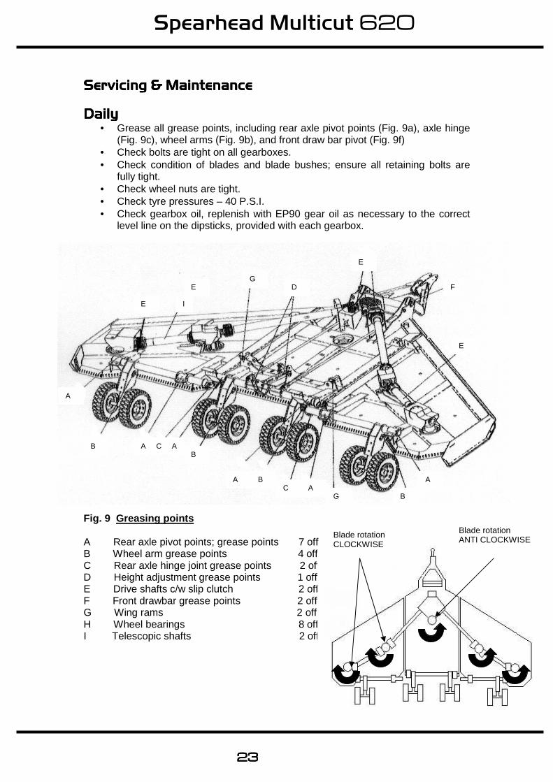
DailyDailyDailyDaily • Grease all grease points, including rear axle pivot points (Fig. 9a), axle hinge
(Fig. 9c), wheel arms (Fig. 9b), and front draw bar pivot (Fig. 9f) • Check bolts are tight on all gearboxes. • Check condition of blades and blade bushes; ensure all retaining bolts are
fully tight. • Check wheel nuts are tight. • Check tyre pressures – 40 P.S.I. • Check gearbox oil, replenish with EP90 gear oil as necessary to the correct
level line on the dipsticks, provided with each gearbox.
Fig. 9 Greasing points A Rear axle pivot points; grease points 7 off B Wheel arm grease points 4 off C Rear axle hinge joint grease points 2 off D Height adjustment grease points 1 off E Drive shafts c/w slip clutch 2 off F Front drawbar grease points 2 off G Wing rams 2 off H Wheel bearings 8 off I Telescopic shafts 2 off
E
I
G D
E
F
E
A
E
A
B G A C
B A
B A C A B
Blade rotation CLOCKWISE
Blade rotation ANTI CLOCKWISE
Spearhead Multicut 620
24242424
Service & MaintenanceService & MaintenanceService & MaintenanceService & Maintenance – Every 8 hours Every 8 hoursEvery 8 hoursEvery 8 hoursEvery 8 hours
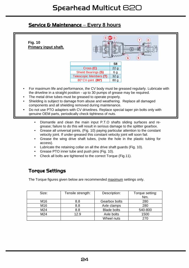
• Dismantle and clean the main input P.T.O shafts sliding surfaces and re-grease; failure to do this will result in serious damage to the splitter gearbox.
• Grease all universal joints, (Fig. 10) paying particular attention to the constant velocity joint. If under-greased this constant velocity joint will soon fail.
• Grease the wing drive shaft tubes, (note the hole in the plastic tubing for access).
• Lubricate the retaining collar on all the drive shaft guards (Fig. 10). • Grease PTO inner tube and push pins (Fig. 10). • Check all bolts are tightened to the correct Torque (Fig.11).
Torque SettingsTorque SettingsTorque SettingsTorque Settings The Torque figures given below are recommended maximum settings only.
Size: Tensile strength: Description: Torque setting: Nm.
M16 8.8 Gearbox bolts 280 M16 8.8 Axle clamps 280 M24 8.8 Blade bolts 540-800 M24 12.9 Axle bolts 1500
Wheel nuts 270
S8 Cross (C) 22 g
Shield Bearings (S) 6 g Telescopic Members (T) 32 g
80° CV-joint (80°) 80 g
• For maximum life and performance, the CV body must be greased regularly. Lubricate with the driveline in a straight position - up to 30 pumps of grease may be required.
• The metal drive tubes must be greased to operate properly. • Shielding is subject to damage from abuse and weathering. Replace all damaged
components and all shielding removed during maintenance. • Do not use PTO adapters with CV drivelines. Replace special taper pin bolts only with
genuine OEM parts, periodically check tightness of nuts.
Fig. 10 Primary input shaft.
Spearhead Multicut 620
25252525
Servicing & MaintenanceServicing & MaintenanceServicing & MaintenanceServicing & Maintenance RegularlyRegularlyRegularlyRegularly
• Check there is no wrapping of string, plastic, grass or other debris between rotor boss and gearbox oil seal.
• Inspect gearbox seals for leaks. • Clear grass and other debris from the deck. • Regularly check the rotor boss retaining castle nut for tightness. First remove
the split pin, select the correct size socket in 3/4” drive and fully tighten the nut. When replacing the split pin, do not slacken the nut to align the hole, always tighten. Failure to regularly check this nut will result in serious wear to hub, which is expensive to repair.
• It is most important that all gearbox bolts are reg ularly checked to be very tight. When the machine is new there will be a ‘bedding in’ period where very frequent checking is important.
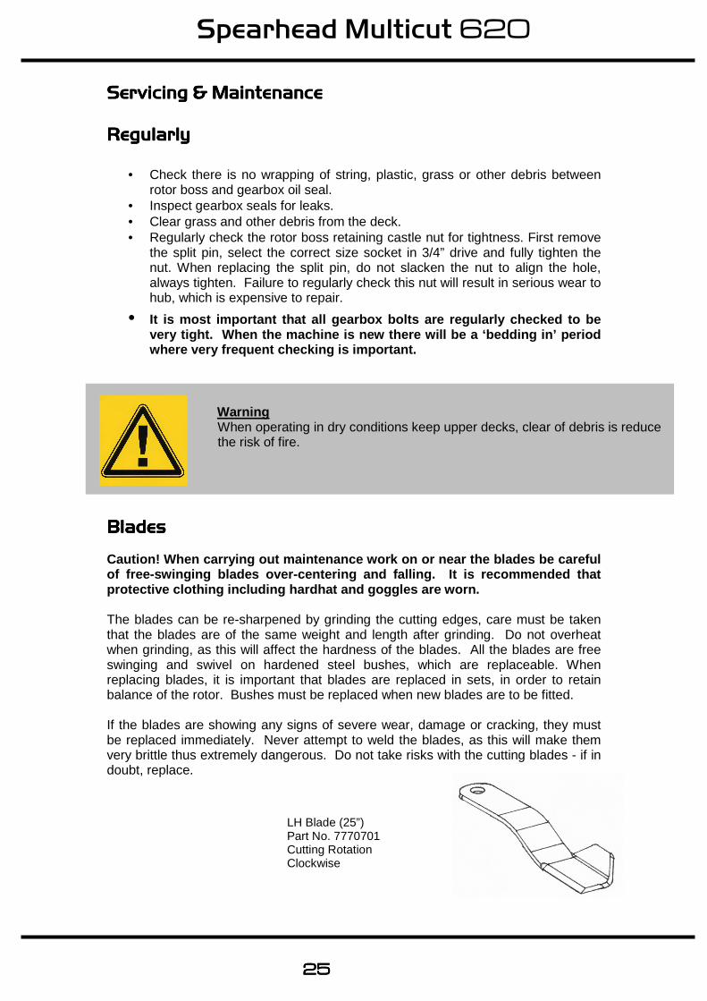
BladesBladesBladesBlades Caution! When carrying out maintenance work on or n ear the blades be careful of free-swinging blades over-centering and falling. It is recommended that protective clothing including hardhat and goggles a re worn. The blades can be re-sharpened by grinding the cutting edges, care must be taken that the blades are of the same weight and length after grinding. Do not overheat when grinding, as this will affect the hardness of the blades. All the blades are free swinging and swivel on hardened steel bushes, which are replaceable. When replacing blades, it is important that blades are replaced in sets, in order to retain balance of the rotor. Bushes must be replaced when new blades are to be fitted. If the blades are showing any signs of severe wear, damage or cracking, they must be replaced immediately. Never attempt to weld the blades, as this will make them very brittle thus extremely dangerous. Do not take risks with the cutting blades - if in doubt, replace.
Warning When operating in dry conditions keep upper decks, clear of debris is reduce the risk of fire.
LH Blade (25”) Part No. 7770701 Cutting Rotation Clockwise

Spearhead Multicut 620
26262626
Clutch Clutch Clutch Clutch MaintenanceMaintenanceMaintenanceMaintenance & Settings& Settings& Settings& Settings BONDIOLI Manufacture (Belleville Spring) Check the condition of the friction discs before use and following periods of storage. Release the tension from the spring, turn the clutch while holding the P.T.O stationary. Adjust the spring compression to the original setting. Following seasonal use, unload the spring tension and store clutch assembly in a dry place. Check condition of friction linings and reset spring compression to original height before use. Should the assembly overheat due to frequent or prolonged clutch slipping, dismantle for inspection. The original thickness of the lining is 3.2mm, replace them when worn to 2.5mm. Clean up all contact surfaces and replace any damaged components before assembly.
BONDIOLI Standard - 3 Blade Per Rotor
Fig No. Position. Part No. Setting. Machine. 2 Centre (2 plate) 5770223 18.9mm 620 (1000rpm) 2 Inner Wing (4 plate) 5770215 17.6mm 620 (1000rpm) 2 Outer Wing (2 plate) 5770207 17.8mm 620 (1000rpm)
Optional - 6 Blade Per Rotor
Fig No. Positi on. Part No. Setting. Machine. 2 Centre (2 plate) 5770223 18.5mm 620 (1000rpm) 2 Inner Wing (4 plate) 5770215 17mm 620 (1000rpm) 2 Outer Wing (2 plate) 5770207 17.2mm 620 (1000rpm)
Note The dimensional setting ‘h’ applies to later type clutches where the 2 discs being measured are of equal diameter.
Warning The slip clutch is there to protect the gearbox. If the blades strike a large obstacle they may get damaged or break - avoid these conditions.
Spearhead Multicut 620
27272727
Servicing & MaintenanceServicing & MaintenanceServicing & MaintenanceServicing & Maintenance SkidsSkidsSkidsSkids When operating on abrasive soils, particularly in stubbles and similar conditions with thin ground cover, excessive skid wear may be expected. To provide extra protection and to prolong life of the skids, special hard facing rods are available.
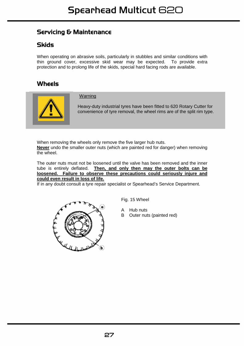
WheelWheelWheelWheelssss When removing the wheels only remove the five larger hub nuts. Never undo the smaller outer nuts (which are painted red for danger) when removing the wheel. The outer nuts must not be loosened until the valve has been removed and the inner tube is entirely deflated. Then, and only then may the outer bolts can be loosened. Failure to observe these precautions cou ld seriously injure and could even result in loss of life. If in any doubt consult a tyre repair specialist or Spearhead’s Service Department.
Warning Heavy-duty industrial tyres have been fitted to 620 Rotary Cutter for convenience of tyre removal, the wheel rims are of the split rim type.
Fig. 15 Wheel A Hub nuts B Outer nuts (painted red)
Spearhead Multicut 620
28282828
StorageStorageStorageStorage Before storing away, thoroughly wash the machine removing all traces of grass and dirt. Great care must be taken when washing with high-pressure hoses, do not hold the water jet close to the paintwork. Use steam cleaners with caution and be sure to remove all detergents to avoid any discoloration or damage to the paintwork. Grease all grease points until fresh grease shows. Liberally apply used engine oil along the whole length of the hinges of each wing section. The centre clutch coupling and wing shafts must be removed and stored under cover. Smear grease on the chrome ramrods for protection
After StorageAfter StorageAfter StorageAfter Storage Disassemble clutches and with an emery cloth remove all traces of rust on the metal clutch plates. Check condition of the friction plates, if there is any sign of over heating, wear or cracking, replace with new. Do not attempt to use the machine with damaged slip clutch plates. Reassemble the clutch units and tighten the bolts to achieve the correct spring length. Do not over tighten or the clutches will not work. Check condition of tyres and pressure then follow the maintenance procedure covered in the servicing part of this manual. Pay particular attention to the condition of guards and blades. Remember the 620 Rotary Cutter is designed to withstand the most rigorous conditions and, with a little care and attention, will give many years of trouble free service. So as not to invalidate the warranty and to avoid problems, use only genuine parts and make sure the machine is not driven at a speed in excess of 1000r.p.m. on the PTO.
Spearhead Multicut 620
29292929
Trouble Shooting Guide
Broken or damaged blades
1. Raise cutting height to avoid striking the ground 2. Remove or avoid obstacles such as rocks
3. Check rotor speed
4. Ensure a steady feed into drive (Do not snatch the PTO)
5. Fit optional stump jumpers
Damaged blade holder
1. As above
2. Failure to keep tight centre retaining nut
Damage gearboxes
1. Seized slip clutch. 2. Telescopic shafts bottoming out
3. Engaging drive with too much power / revs
4. Lack of grease on sliding tubes of drive shaft
Damage to PTO shaft
1. Seized slip clutch 2. Telescopic tube bottoming out 3. Engaging drive with too much power / revs
4. Turning too sharp
5. Not enough overlap
6. Lack of grease
7. Build up of Debris under drive shaft
Gearbox overheating
1. Incorrect oil level 2. Incorrect grade of oil 3. Incorrect operating speed 4. Machine overloaded 5. Rubbish around the gearbox reducing air circulation
Slip clutches overheating
1. Machine overloaded
2. Incorrect operating speed
3. Incorrect setting
4. Blades hitting the ground Oil leak from gearbox
1. Damaged shaft seal check for foreign matter (wire-string)
2. Faulty breather
3. Damaged gasket
4. Incorrect oil level Metal fatigue on frame
1. Too fast a traveling / operating speed for conditions
2. Wings not floating i.e. following the ground contours (check tractor spool)
3. Used in a manner or condition contra to its intended purpose
Excessive skid wear 1. Set skids above the ground

Spearhead Multicut 620
30303030

Spearhead Multicut 620
31313131
Spearhead Machinery Green View
Salford Priors Evesham
Worcestershire WR11 8SW
Tel: 01789 491860 Fax: 01789 778683
www.spearheadmachinery.com [email protected]


![Fresa finitrice Multicut XF - FRAISA · 2020-03-18 · Fresa finitrice Multicut XF Produkt_Multicut_XF_IT_ks0 • mk • 16. Juni 2015 • 217-4095 [ 2 ] La nuova Multicut XF viene](https://img.dokumen.tips/doc/110x75/5f0de2c27e708231d43c90ef/fresa-finitrice-multicut-xf-fraisa-2020-03-18-fresa-finitrice-multicut-xf-produktmulticutxfitks0.jpg)