Embed Size (px)
DESCRIPTION
lab manual
Citation preview
USER'S MANUAL
FOR
VMC-8603
8086/88 BASED
MICROPROCESSOR TRAINING
CUM-DEVELOPMENT KIT
(NEW MODEL - 1.02)
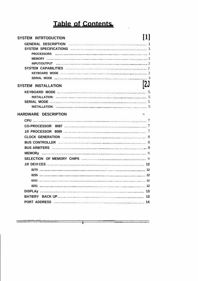
Table of Contents
SYSTEM INTRTODUCTION [1]GENERAL DESCRIPTION 1SYSTEM SPECIFICATIONS 1
PROCESSORS 1MEMORY 2INPUT/OUTPUT 2
SYSTEM CAPABILITIES 2KEYBOARD MODE 2SERIAL MODE 3
SYSTEM INSTALLATION [2JKEYBOARD MODE 5
INSTALLATION: 5SERIAL MODE 5
INSTALLATION: 5
HARDWARE DESCRIPTION ~CPU 7CO-PROCESSOR 8087 71/0 PROCESSOR 8089 7CLOCK GENERATION 8BUS CONTROLLER 8BUS ARBITERS ,.. 8MEMORy 9SELECTION OF MEMORY CHIPS 91/0 DEVI CES 12
8279 128255 128253 12
8251 12DiSPLAy 13BATIERY BACK UP 13PORT ADDRESS 14
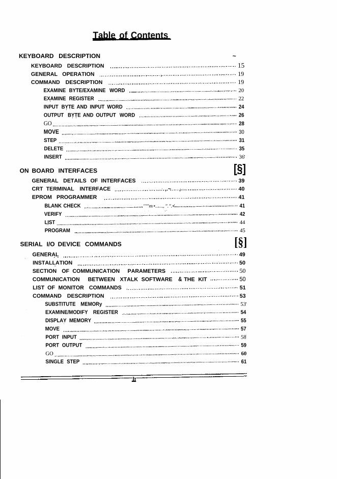
Table of Contents
KEYBOARD DESCRIPTION ~KEYBOARD DESCRIPTION 15GENERAL OPERATION , 19COMMAND DESCRIPTION 19
EXAMINE BYTE/EXAMINE WORD 20EXAMINE REGISTER 22INPUT BYTE AND INPUT WORD 24OUTPUT BYTE AND OUTPUT WORD 26GO 28MOVE 30STEP 31DELETE 35INSERT 36
ON BOARD INTERFACES [§]GENERAL DETAILS OF INTERFACES 39CRT TERMINAL INTERFACE ,.~ , 40EPROM PROGRAMMER 41
BLANK CHECK '''"m•.......".".•' 41VERIFY 42LIST 44PROGRAM 45
SERIAL I/O DEVICE COMMANDS [§]GENERAL 49INSTALLATION 50SECTION OF COMMUNICATION PARAMETERS 50COMMUNICATION BETWEEN XTALK SOFTWARE & THE KIT 50LIST OF MONITOR COMMANDS 51COMMAND DESCRIPTION 53
SUBSTITUTE MEMORy 53EXAMINE/MODIFY REGISTER 54DISPLAY MEMORY 55MOVE 57PORT INPUT 58PORT OUTPUT 59GO 60SINGLE STEP 61
It
Table of Contents
READ HEX FILE 62WRITE HEX FILE 63UPLOADI NG 64DOWNLOADING 65ABORTING THE OPERATION 65
SAMPLE PROGRAMS [Z]INTRODUCTION 67PROGRAMMING EXAMPLE 67USE OF 8087 PROCESSOR 79
CONNECTOR DETAILS ~INTRODUCTION 87DETAILS OF CONNECTOR J1 87DETAILS OF CONNECTOR J2 88DETAILS OF CONNECTOR J3 88DETAILS OF CONNECTOR J4 88DETAILS OF CONNECTOR J5 89DETAILS OF CONNECTOR J6 89DETAILS OF CONNECTOR J7 90DETAILS OF CONNECTOR J13 90DETAILS OF JUMPER JP1 90DETAILS OF JUMPER JP2 90DETAILS OF JUMPER JP3 91DETAILS OF JUMPER JP4 91DETAILS OF JUMPER JP5 91DETAILS OF JUMPER JP6 91DETAILS OF JUMPER JP7 92DETAILS OF JUMPER JP8 92DETAILS OF JUMPER JP9 92
ASSEMBERIDISASSEMBLER ~INSTALLATION 93COMMANDS 94EDITING COMMANDS 98
iii
SYSTEM INTRODUCTION
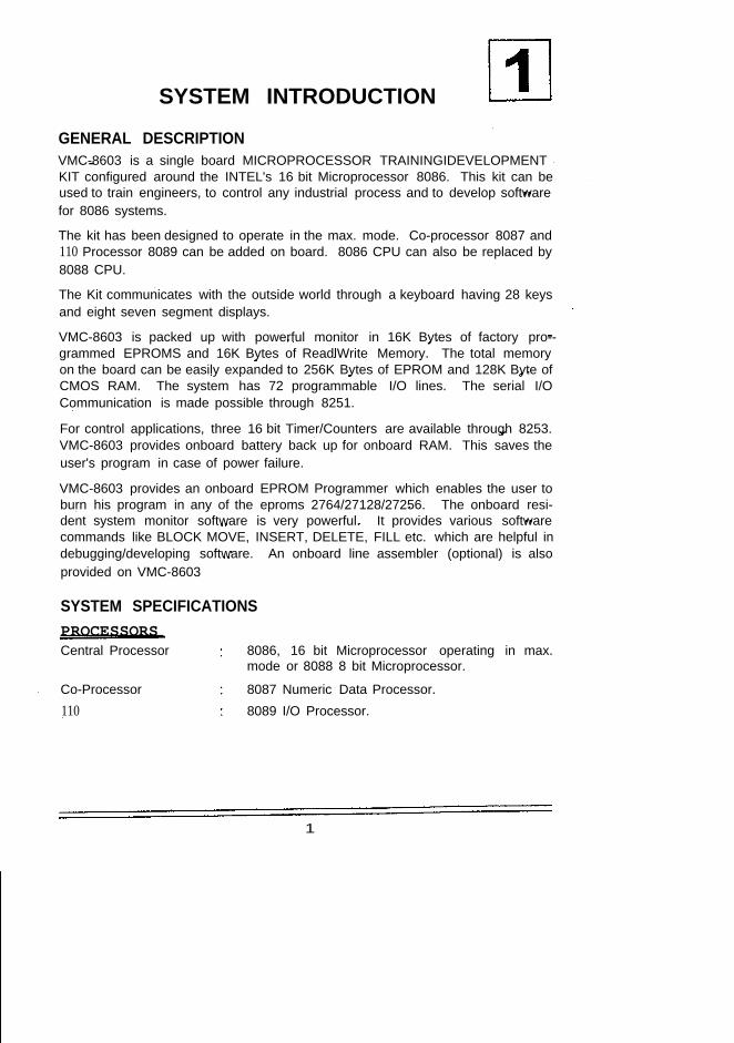
GENERAL DESCRIPTIONVMC-8603 is a single board MICROPROCESSOR TRAININGIDEVELOPMENTKIT configured around the INTEL's 16 bit Microprocessor 8086. This kit can beused to train engineers, to control any industrial process and to develop softwarefor 8086 systems.
The kit has been designed to operate in the max. mode. Co-processor 8087 and110 Processor 8089 can be added on board. 8086 CPU can also be replaced by8088 CPU.
The Kit communicates with the outside world through a keyboard having 28 keysand eight seven segment displays.
VMC-8603 is packed up with powerful monitor in 16K Bytes of factory pro--grammed EPROMS and 16K Bytes of ReadlWrite Memory. The total memoryon the board can be easily expanded to 256K Bytes of EPROM and 128K Byte ofCMOS RAM. The system has 72 programmable I/O lines. The serial I/OCommunication is made possible through 8251.
For control applications, three 16 bit Timer/Counters are available through 8253.VMC-8603 provides onboard battery back up for onboard RAM. This saves theuser's program in case of power failure.
VMC-8603 provides an onboard EPROM Programmer which enables the user toburn his program in any of the eproms 2764/27128/27256. The onboard resi-dent system monitor software is very powerful. It provides various softwarecommands like BLOCK MOVE, INSERT, DELETE, FILL etc. which are helpful indebugging/developing software. An onboard line assembler (optional) is alsoprovided on VMC-8603
SYSTEM SPECIFICATIONSPROCESSORSCentral Processor 8086, 16 bit Microprocessor operating in max.
mode or 8088 8 bit Microprocessor.
Co-Processor 8087 Numeric Data Processor.110 8089 I/O Processor.
1
VMC·8086188M User's Manual V"mytics
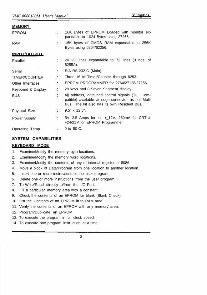
MEMORYEPROM
RAM
INPUT/OUTPUTParallel
SerialTIMER/COUNTEROther InterfacesKeyboard & Display
BUS
Physical Size
Power Supply
Operating Temp.
16K Bytes of EPROM Loaded with monitor ex-pandable to 1024 Bytes using 27256.16K bytes of CMOS RAM expandable to 256KBytes using 6264/62256.
24 I/O lines expandable to 72 lines (3 nos. of8255A).EIA RS-232-C (Main).Three 16 bit Timer/Counter through 8253.EPROM PROGRAMMER for 2764/27128/27256.28 keys and 8 Seven Segment display.All address, data and control signals (TIL Com-patible) available at edge connector as per MultiBus. The kit also has its own Resident Bus.9.5" x 12.5".
5V, 2.5 Amps for kit, +_12V, 250mA for CRT &+24/21V for EPROM Programmer
o to 50·C.
SYSTEM CAPABILITIESKEYBOARD MODE1. Examine/Modify the memory byte locations.2. Examine/Modify the memory word locations.3. Examine/Modify the contents of any of internal register of 8086.4. Move a block of Data/Program from one location to another location.5. Insert one or more instructions in the user program.6. Delete one or more instructions from the user program.7. To Write/Read directly to/from the I/O Port.8. Fill a particular memory area with a constant.9. Check the contents of an EPROM for blank (Blank Check).10. List the Contents of an EPROM in to RAM area.11. Verify the contents of an EPROM with any memory area.12. Program/Duplicate an EPROM.13. To execute the program in full clock speed.14. To execute one program instruction at a time.
2
Vinytics VMC·8086188M User's Manual
SERIAL MODE1, Display/Modify memory location.2. Display/Modify internal registers of 8086.3. Display Block of memory data.4. Move a block of Data/Program from one location to another location.5. Execute the program in full clock speed mode.6. To execute one program instruction at a time.
7. Port Input8. Port Output9. Read Hex file10. Write Hex file
3
SYSTEM INSTAllATION
KEYBOARD MODETo install VMC-8603 in keyboard mode, the following additional things are re-quired.
1. Power Supply (+5V/2.5 Amp.)
INSTALLATION:1. Select the memory chips (EPROM and RAM) as per your requirement by
changing the jumper connections as mentioned in Chapter - 3 under theheading Memory. If no change is to be done, go ahead.
2. Connect the Power Supply wires (GND & +5V) of the supply connectormarked for various voltage.
3. Switch on the Power Supply.4. A message - UP 86 will come on display (PRESS RESET if you do not get -
UP 86) and can now use the system.
SERIAL MODETo install VMC-8603 in serial mode, the following additional things are required.
1. Power Supply +5V12.5 Amp., +_ 12V/250mA2. CRT Terminal with RS-232-C serial interface.
3. SERIAL CABLE from kit to Terminal
INSTALLATION:Steps 1 and 2 are same as mentioned earlier in keyboard mode.
3. Connect the Power Supply wires (GND, +5V, +12V and -12V) of the kit
supply connector marked for various voltages.
4. Connect the cable from the CRT Terminal to the Main RS-232-C interface ofthe kit marked as J3 Connector.
5. Set the Baud rate of the kit to the desired value by changing the jumperposition as mentioned in Chapter - 5.
6. Switch on VMC-8603 and Press Reset.
7. Switch ON the terminal and set the same baud rate in the terminal asselected for VMC-8603.
5
VMC.8086188M User's Manual V'mytics
8. Press CRT Key on VMC-8603. A message Serial will be displayed on the kitand a message VMC-8603 version 1.2 will come on the screen and in thenext line it displays a prompt character '.', indicating that now the commandcan be entered from the terminal. The detail about the connector J3 aregiven in Chapter - 5.
One can now give the commands as mentioned in Chapter-6 under the heading"Serial I/O Commands".
6
HARDWARE DESCRIPTION
CPU8086 is a 16 bit, third generation microprocessor and is suitable for an excep-tionally wide spectrum of microcomputer applications. This flexibility is one ofmost outstanding characteristics.
8086 has got 16 data lines and 20 address lines. The lower 16 address lines aremUltiplexed with 16 data lines. Hence it becomes necessary to latch the addresslines. This is done by using 74 LS 373. In fact several of the 40 CPU pins havedual functions that are selected by a strapping pin. In this kit 8086 is used in themax. mode (MN/Mx input held logically low).
The 8088 is designed with an 8-bit external path to memory and 110. Except thatthe 8086 can transfer 16 bits at a time, the two processors & software areidentical in almost every respect. Software identical in almost every respect.Software written for one CPU will execute on the other without alteration. Thetwo processors are designed to operate with the 8089 I/O processors and otherprocessors in multiprocessing and distributed processing systems.
The INTR, TEST & Hold Inputs to 8086 are pulled down and are brought out atPCB FRC connector. The 8086's NMI Input is connected to the VCT INT Key.
The maskable interrupt INTR is available to the peripheral circuits through theexpansion Bus. To use the maskable interrupt an interrupt vector pointer mustbe provided on the data bus when INTA is active. An interrupt Controller Circuitis provided to take care of more than one source of interrupt.
CO-PROCESSOR 8087The 8087 Co-processor "hooks" have been designed into the 8086 and 8088so that this types of processor can be accommodated in the future. A co-processor differs from an independent processor in that it obtains its instruc-tions from another processor, called a host. The co-processor monitors in-structions fetched by the host and recognizes certain of these as its own andexecutes them. A co-processor, in effect, extends the instruction set of itshost computer.
I/O PROCESSOR 8089The 8086 and 8088 are designed to be used with the 8089 in high performance 1/o applications. The 8089 inconceptually resembles a microprocessor with twoDMA channels and an instruction set specifically tailored for I/O operations.Unlike simple DMA controllers, the 8089 can service I/O devices directly, remov-ing this task from the CPU. In addition, it can transfer data on its own bus or on
7
VMC·8086188M User's Manual Vinytics
the system bus, can match 8-bit or 16-bit peripherals to 8-bit or 16-bit buses,and can transfer data from memory to memory and from I/O devices to I/Odevice. 8089 has been used here in local mode.
CLOCK GENERATIONThe clock generator circuit is an Intel's 8284 clock generator/driver. The circuitaccepts a crystal input which operates at a fundamental frequency of 14.7456MHz. (14.7456 MHz
was selected since this frequency is a multiple of the baud rate clock and alsoprovides a suitable frequency for the CPU). The clock generator/driver dividesthe crystal frequency by three to produce the 4.9 MHz ClK signal required by theCPU. Additionally, the clock generator performs a further divide-by-two outputcalled PCLK (peripheral clock) which is the primary clock signal used by theremainder of the circuits.
The clock generator/driver provides two control signal outputs which are syn-chronized (internally) to the 4.9 MHz ClK signal; RDY (ready) and RST (reset).RST is used to reset the VMC-8603 to an initialized state that occurs when theRES input goes low (when power first is applied or when the SYSTEM RESETkey is pressed).
The system can operate at either 4.9 MHz or 2.45 MHz. This is selected by a setof jumpers JP1 on the right hand side of the 8284 clock generator as shownbelow:
fiIil 1 4.9 MHz~ 2 2.45 MHz (lOWER)
The VMC-8603 is suppled in 4.9 MHz configuration.
BUS CONTROLLERThe 8288 is a Bus Controller which decodes status signals output by an 8089, ora maximum mode 8086 or 8088. When these signals indicate that the processoris to run a bus cycle, the 8288 issues a bus command that identifies the buscycle as memory read, memory write, I/O read, I/O write, etc. It also provides asignal that strobes the address into latches. The 8288 provides the drive levelneeded for the bus control lines in medium to large systems.
BUS ARBITERSThe 8289 is a Bus Arbiter that controls the access of a processor to a multimastersystem resources (typically memory) that is shared by two or more microproces-sors (masters). Arbiters for each master may use one of several priority-resolv-ing techniques to ensure that only one master drives the shared Bus.
8
\'inytics VMC·8086188M User's Manual
MEMORYVMC-8603 provides 16K Bytes of EPROM loaded with monitor and 16K bytes ofCMOS RAM. The total onboard memory can be configured as follows:
EPROM 512 bytes of EPROM using 27C010, 1024 bytes using27C020 & 256K bytes using 62C1024.64K Bytes of RAM using '62256.RAM
The system provides four 28/32 Pin sockets for the EPROM area named asMEM1 to MEM3 and four 28/32 Pin sockets for the RAM area named as MEM2to MEM4. EPROMO to EPROM3 can be defined to have either of the EPROM27128/27256/27512/27C010/27C020 and the MEM2 to MEM4 can be defined tohave either of 6264/62256/62C1024. This selection is done by changing thejumper connections on the board of the kit.
With the 20 bit address of 8086, a total of 1 Mega Bytes of memory can beaddressed with the address slot as 00000 to FFFFF. The actual memory areawill depend upon the memory chips selected and accordingly the addresses ofthe various memory sockets will change.
On VMC-8603 the 16K Bytes of RAM area is provided the bottom most slot andthe 16K byte of EPROM area is provided the top most slot.
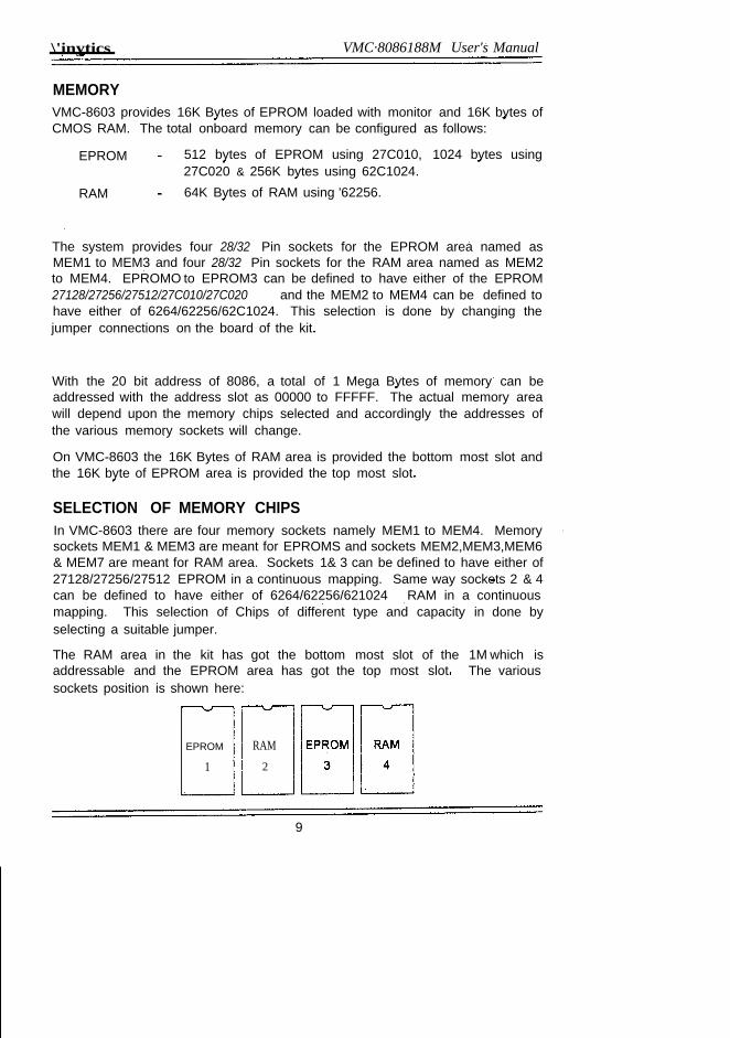
SELECTION OF MEMORY CHIPSIn VMC-8603 there are four memory sockets namely MEM1 to MEM4. Memorysockets MEM1 & MEM3 are meant for EPROMS and sockets MEM2,MEM3,MEM6& MEM7 are meant for RAM area. Sockets 1& 3 can be defined to have either of27128/27256/27512 EPROM in a continuous mapping. Same way sockets 2 & 4can be defined to have either of 6264/62256/621024 RAM in a continuousmapping. This selection of Chips of different type and capacity in done byselecting a suitable jumper.
The RAM area in the kit has got the bottom most slot of the 1M which isaddressable and the EPROM area has got the top most slot. The varioussockets position is shown here:
EPROM
1RAM2
9
VMC.8086188M User's Manual Vmytics
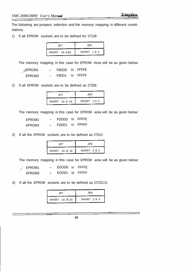
The following are jumpers selection and the memory mapping in different combi-nations.
1) If all EPROM sockets are to be defined for 27128:
JP7
SHORT 1A &'16
JP9
SHORT 1 & 2
The memory mapping in this case for EPROM Area will be as given below:
,-EPROM1
EPROM3
F8DDDF8DD1
to FFFFEto FFFFF
2) If all EPROM sockets are to be defined as 27256:
JP7
SHORT 1A & 16
JP9
SHORT 1 to 2
The memory mapping in this case for EPROM area will be as given below:
EPROM1EPROM3
FDDDDFDDD1
to FFFFEto FFFFF
3) If all the EPROM sockets are to be defined as 27512:
JP7
SHORT 1A & 16
JP9
SHORT 2 & 3
The memory mapping in this case for EPROM area will be as given below:
EPROM1EPROM3
EDODD to FFFFEEOOD1 to FFFFF
4) If all the EPROM sockets are to be defined as 27CD1 D:
JP7
SHORT 1A s 2A
JP9
SHORT 2 & 3
10
V'mytics VMC·8086188M User's Manual
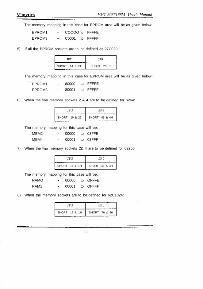
The memory mapping in this case for EPROM area will be as given below:
EPROM1 COOOO to FFFFEEPROM3 C0001 to FFFFF
5) If all the EPROM sockets are to be defined as 27C020:
JP7
SHORT 1A & 2A
JP9
SHORT 2& 3
The memory mapping in this case for EPROM area will be as given below:
EPROM1EPROM3
8000080001
to FFFFEto FFFFF
6) When the two memory sockets 2 & 4 are to be defined for 6264:
JP3 JP4SHORT 16 & 26 SHORT 46 & 4H
The memory mapping for this case will be:MEM2 00000 to 03FFEMEM4 00001 to 03FFF
7) When the two memory sockets 2& 4 are to be defined for 62256
JP3 JP4SHORT 16 & 1H SHORT 46 & 4H
The memory mapping for this case will be:RAMO 00000 to OFFFERAM1 00001 to OFFFF
8) When the memory sockets are to be defined for 62C1024:
JP3 JP5SHORT 16 & 1H SHORT 76 & 66
11
VMC-8086/88M User's Manual Vinytics
, The memory mapping for this case will be:., RAMO 00000 to OFFFE
RAM1 00001 to OFFFF
110 DEVICES82798279 is a general purpose programmable keyboard and display I/O interfacedevice designed for use with the 8086 microprocessor, It provides a scannedinterface to 28 contact key matrix provided in VMC-8603 and scanned displays,
8279 has got 16 x 8 display RAM which can be loaded or interrogated by theCPU. When a key is pressed, its corresponding code is entered in the FIFOqueue of 8279 and can now be read by the Microprocessor. 8279 also refreshesthe display RAM automatically.
82558255 is a programmable peripheral interface (PPI) designed to use with 8086Microprocessor. This basically acts as a general purpose I/O component tointerface peripheral equipments to the system bus. It is not necessary to havean external logic interface with peripheral devices since the functional configura-tion of 8255 is programmed by the system software. It has got three input/output ports of 8 lines each (PORT-A, PORT-B and PORT-C). Port-C can bedivided into two ports of 4 lines each named as Port-C upper and Port-C lower.Any Input/Output combination of Port-A, Port-B, Port-C upper and Port-C lowercan be defined using the appropriate software commands, The Port addressesfor these ports are given here. VMC-8603 provides nine Input/Output ports of 8lines each using three 8255 chips, These ports are brought out at connectorsC10, C9, C11.
8253This chip is a programmable interval timer/counter and can be used for thegeneration of accurate time delays under software control. Various other func-tions that can be implemented with this chip are programmable rate generator.Event Counter, Binary rate rnultipller, real time clock etc. This chip has got threeindependent 16 bit counters each having a count rate of up to 2 MHz, The CLK,GATE & OUT signals of these timers are brought out at the C5 connector.
8251This chip is a programmable communication interface and is used as a periph-eral device. This device accepts data characters from the CPU in parallel formand then converts them into a continuous serial data stream for transmission.Simultaneously it can receive serial data stream and converts them into parallel
12
Viftytics VMC·8086188M User's Manual
data characters for the CPU. This chip will signal the CPU whenever it canaccept a new character for transmission or whenever it has received a characterfor the CPU. The CPU can read the complete status of it at any time. 8251 hasbeen utilized in VMC-8603 for Main/Aux. RS-232-C interface and 20mA currentloop.
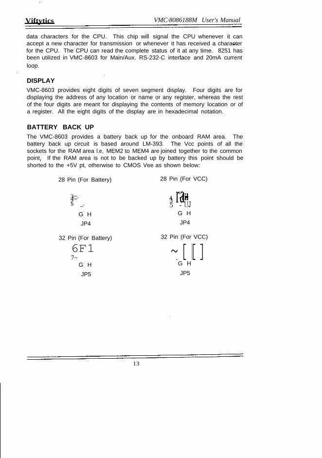
DISPLAYVMC-8603 provides eight digits of seven segment display. Four digits are fordisplaying the address of any location or name or any register, whereas the restof the four digits are meant for displaying the contents of memory location or ofa register. All the eight digits of the display are in hexadecimal notation.
BATTERY BACK UPThe VMC-8603 provides a battery back up for the onboard RAM area. Thebattery back up circuit is based around LM-393. The Vcc points of all thesockets for the RAM area l.e, MEM2 to MEM4 are joined together to the commonpoint. If the RAM area is not to be backed up by battery this point should beshorted to the +5V pt. otherwise to CMOS Vee as shown below:
28 Pin (For Battery)
3~.4~5 _.
G HJP4
28 Pin (For VCC)
3 ra-4 -fil5 - l.!J
G HJP4
32 Pin (For Battery)
6F17~
G HJP5
32 Pin (For VCC)~[[]G HJP5
13
VMC·8086188M User's Manual Vinytics
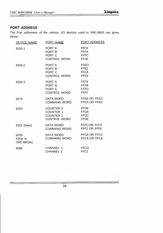
PORT ADDRESSThe Port addresses of the various I/O devices used in VMC-8603 are givenbelow:
DEVICE NAME PORT NAME PORT ADDRESS
8255-1 PORT A FFF8PORT B FFFAPORT C FFFCCONTROL WORD FFFE
8255-2 PORT A FFEOPORT B FFE2PORT C FFE4CONTROL WORD FFE6
8255-3 PORT A FFF9PORT B FFFBPORT C FFFDCONTROL WORD FFFF
8279 DATA WORD FFE8 OR FFECCOMMAND WORD FFEA OR FFEE
8253 COUNTER 0 FFD8COUNTER 1 FFDACOUNTER 2 FFDCCONTROL WORD FFDE
8251 (Main) DATA WORD FFFOOR FFF4COMMAND WORD FFF2 OR FFF6
8259 DATA WORD FFC8 OR FFCC(Only in COMMAND WORD FFCA OR FFCEVMC-8603A)
8089 CHANNEL 1 FFCOCHANNEL 2 FFC1
14
KEYBOARD DESCRIPTION
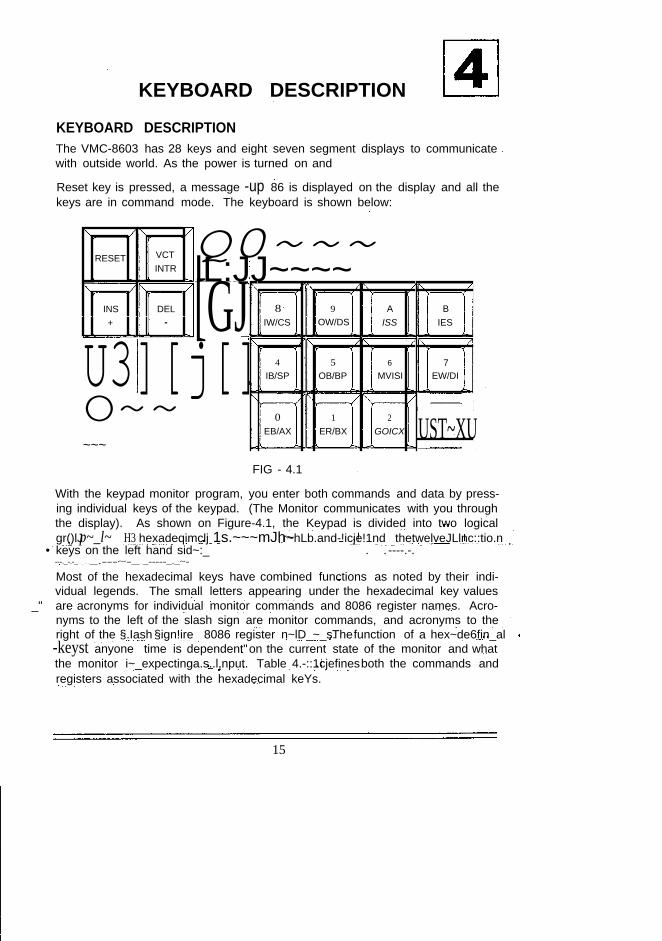
KEYBOARD DESCRIPTIONThe VMC-8603 has 28 keys and eight seven segment displays to communicatewith outside world. As the power is turned on and
Reset key is pressed, a message -up 86 is displayed on the display and all thekeys are in command mode. The keyboard is shown below:
RESET VCTINTR
INS DEL+ -
Q0~~~lL:JJ~~~~[GJU3][j[]O~~
~~~
8 9 A BIW/CS OW/DS ISS IES
4 5 6 7IB/SP OB/BP MVISI EW/DI
0 1 2 UST~XUEB/AX ER/BX GOICX
FIG - 4.1
With the keypad monitor program, you enter both commands and data by press-ing individual keys of the keypad. (The Monitor communicates with you throughthe display). As shown on Figure-4.1, the Keypad is divided into two logicalgr()lJp~_l~ H3 hexadeqimclj 1s.~~~mJh~r~hLb.and-!icje!1nd thetwelveJLlnc::tio.n
• keys on the left hand sid~:_ . . ----.-.---._-.-_ .. __ ..._.---~-_ .._-----_._~-
Most of the hexadecimal keys have combined functions as noted by their indi-vidual legends. The small letters appearing under the hexadecimal key values
_" are acronyms for individual monitor commands and 8086 register names. Acro-nyms to the left of the slash sign are monitor commands, and acronyms to theright of the §.Iash §ign!ire 8086 register n~lD_~_s.,Thefunction of a hex~de6fin_al-keyst anyone time is dependent"on the current state of the monitor and whatthe monitor i~_expectinga.s..l,nput. Table 4.-::1cjefinesboth the commands andregisters associated with the hexadecimal keYs.
15
VMC-8086188M User's Manual Vinyties
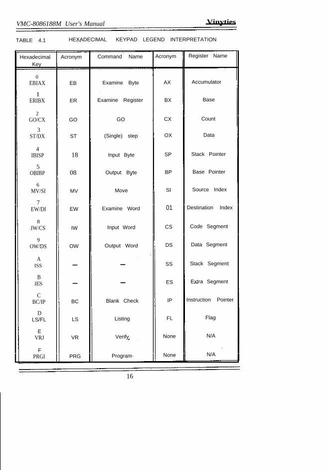
TABLE 4.1 HEXADECIMAL KEYPAD LEGEND INTERPRETATION
Hexadecimal Acronym Command Name Acronym Register NameKey
0EBIAX EB Examine Byte AX Accumulator
1ERlBX ER Examine Register BX Base
2GO/CX GO GO CX Count
3ST/DX ST (Single) step OX Data
4IBISP 18 Input Byte SP Stack Pointer
5OBlBP 08 Output Byte BP Base Pointer
6MV/SI MV Move SI Source Index
7EW/DI EW Examine Word 01 Destination Index
8IW/CS IW Input Word CS Code Segment
9OW/DS OW Output Word DS Data Segment
AISS - - SS Stack Segment
BIES - - ES Extra Segment
CBC/IP BC Blank Check IP Instruction Pointer
DLS/FL LS Listing FL Flag
EVRJ VR Verify None N/A
FPRGI PRG Program· None N/A
16
Vinyties VMC.8086188M User's Manual
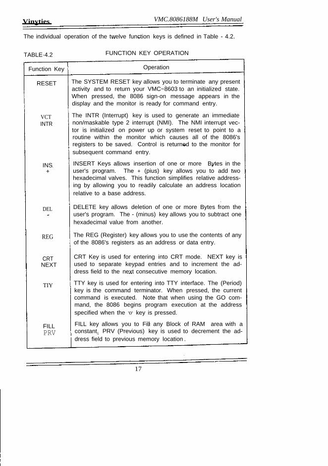
The individual operation of the twelve function keys is defined in Table - 4.2.
TABLE·4.2
Function Key
RESET
VCTINTR
INS+
DEL
REG
CRTNEXT
TIY
FILLPRV
FUNCTION KEY OPERATION
Operation
The SYSTEM RESET key allows you to terminate any presentactivity and to return your VMC~8603 to an initialized state.When pressed, the 8086 sign-on message appears in thedisplay and the monitor is ready for command entry.
The INTR (Interrupt) key is used to generate an immediatenon/maskable type 2 interrupt (NMI). The NMI interrupt vec-tor is initialized on power up or system reset to point to aroutine within the monitor which causes all of the 8086'sregisters to be saved. Control is returned to the monitor forsubsequent command entry.
INSERT Keys allows insertion of one or more Bytes in theuser's program. The + (pius) key allows you to add twohexadecimal valves. This function simplifies relative address-ing by allowing you to readily calculate an address locationrelative to a base address.
DELETE key allows deletion of one or more Bytes from theuser's program. The - (minus) key allows you to subtract onehexadecimal value from another.
The REG (Register) key allows you to use the contents of anyof the 8086's registers as an address or data entry.
CRT Key is used for entering into CRT mode. NEXT key isused to separate keypad entries and to increment the ad-dress field to the next consecutive memory location.
TTY key is used for entering into TTY interface. The (Period)key is the command terminator. When pressed, the currentcommand is executed. Note that when using the GO com-mand, the 8086 begins program execution at the addressspecified when the '0' key is pressed.
FILL key allows you to Fill any Block of RAM area with aconstant. PRV (Previous) key is used to decrement the ad-dress field to previous memory location .
.
17
VMC.8086188M User's Manual Vinytics
Function Key Operation
F1 User definable key.
F2 User definable key.
F3 User definable key.
Your VMC-8603 Kit uses the eight digit display to communicate with you. De-pending on the current state of the monitor, the information displayed will be the:
~ Current contents of a register or memory location.~ An "echo" of a hexadecimal key entry.~ A monitor prompt sign.~ An information of status message.
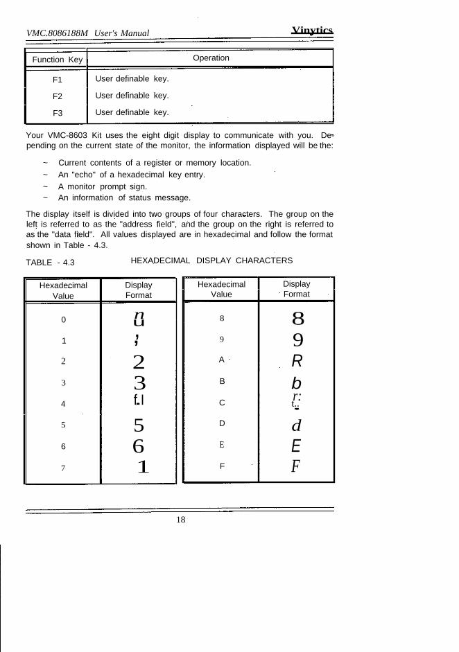
The display itself is divided into two groups of four characters. The group on theleft is referred to as the "address field", and the group on the right is referred toas the "data field". All values displayed are in hexadecimal and follow the formatshown in Table - 4.3.
TABLE - 4.3 HEXADECIMAL DISPLAY CHARACTERS
Hexadecimal DisplayValue Format
0 nu1
,,2 23 34 f.I5 56 67 1
Hexadecimal DisplayValue Format
8 89 9A RB bC r:t..D dE EF F
18
Vinytics VMC.8086188M User's Manual
GENERAL OPERATIONWhen using the keypad monitor, you will be prompted through the display as tothe input required. Whenever the monitor is expecting a command entry, aminus sign or dash appears in the most significant display digit of the addressfield. Pressing one of the hexadecimal command keys (Keys O-F) when thedash is displayed is interpreted as a command entry. When the key is pressed,the dash disappears and a decimal point (or decimal points) appears in the leastsignificant display digit (or least significant digits) of the address field to indicatethat subsequent keypad entry will be directed to the address field. Note thatdepending on the command, characters also may appear within the address anddata fields. Monitor operation from this point is determined by the actual com-mand entered. The description of each command is given later on in thischapter.
Following power on or whenever the system RESET key is pressed, the monitorinitializes the VMC-8603and displays, the monitor sign-on message (UP in thetwo least signift'Cantdigits of the data field) and the command prompt character(dash) in the most significant digit of the address field. Note that in the followingcommand descriptions, the monitor always calculates a 20-bit physical memory.eddresa from a 16 bit segment address value and a 16 bit offset adqIe.!>s",~!ue.The segment address value is entered first, the ":"keyis pressed (to separatethe two entries), and then the offset address value js anterelL"The two valuesentered, which are displaced from one another by four bits, are added togetherto form the 20-bit physical memory address. If only one address value isenterecj (the colon must be omitted), it is interpreted by the rrionlfor as an offset'address value enter, and the current contents 0.1 the codesegment(CS) registerare' used as the segment address value. The CS register contents and offsetaddress value entered are combined to form the 20-bit physical address...
COMMANDDEsc~pnONThe various commands that can be executed by the monitor are listed below:
~ EXAMINE BYTE~ EXAMINE WORD.~ EXAMINE REGISTER~ INPUT BYTE~ INPUT WORD-¢- OUTPUT BYTE~ OUTPUT WORD~ GO~ MOVE~ STEP
19
VMC·8086188M User's Manual Vinytica
-¢- INSERT-¢- DELETE-¢- FILL-¢- BLANK CHECK-¢- VERIFY-¢- LIST-¢- PROGRAM/DUPLICATE
During the description of the commands the following notations are used:
@[AJ[AJ.o<B>
indicate a keyboard keyindicate that" A" Is optionalindicate one or more optional occurrences of" A"indicate that "B" is a variable
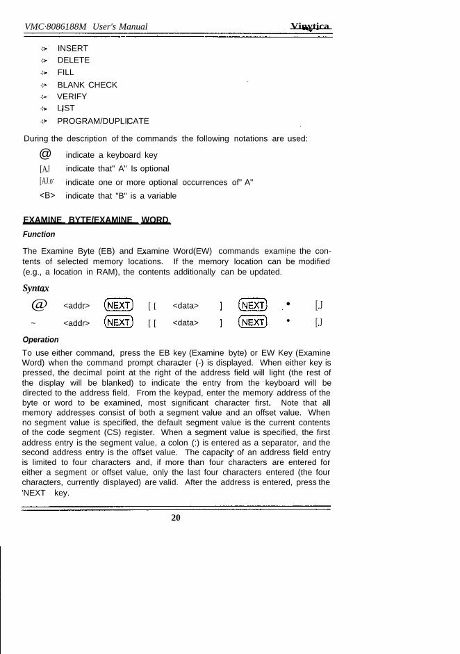
EXAMINE BYTE/EXAMINE WORDFunction
The Examine Byte (EB) and Examine Word(EW) commands examine the con-tents of selected memory locations. If the memory location can be modified(e.g., a location in RAM), the contents additionally can be updated.
Syntax
@ <addr>
~ <addr>
[ [
[ [
<data> • [.J[.J<data> •
OperationTo use either command, press the EB key (Examine byte) or EW Key (ExamineWord) when the command prompt character (-) is displayed. When either key ispressed, the decimal point at the right of the address field will light (the rest ofthe display will be blanked) to indicate the entry from the keyboard will bedirected to the address field. From the keypad, enter the memory address of thebyte or word to be examined, most significant character first. Note that allmemory addresses consist of both a segment value and an offset value. Whenno segment value is specified, the default segment value is the current contentsof the code segment (CS) register. When a segment value is specified, the firstaddress entry is the segment value, a colon (:) is entered as a separator, and thesecond address entry is the offset value. The capacity of an address field entryis limited to four characters and, if more than four characters are entered foreither a segment or offset value, only the last four characters entered (the fourcharacters, currently displayed) are valid. After the address is entered, press the'NEXT key.
20
Vinytics VMC·8086188M User's Manual
The data byte or word contents of the addressed memory location will be dis-played in the data field, and a decimal point will appear at the right of the datafield to indicate that any subsequent hexadecimal keypad entry will be directedto the data field. Note that when using the Examine Word Command, the bytecontents of the memory location displayed appear in the two least significantdigits of the data field, and the byte contents of the next consecutive memorylocation (memory address + 1) appear in the two most-significant digits of thedata field.
If the contents of the memory location addressed only are to be examined pressthe "key to examine the next consecutive memory location (Examine Byte com-mand) or the next two consecutive memory locations (Examine Word Com-mand). One can also press "PRV" key to examine the previous memory loca-tion/locations. To modify the contents of an address memory location, key-inthe new data field is limited to either two (examine byte) or four (examine word)characters and that if more characters are entered, only the characters currentlydisplayed in the field are valid. The data displayed is not updated in memoryuntil either the ". or "NEXT" key is pressed. If the". key is pressed, the commandis terminated, and the command prompt character is displayed in the addressfield. If the" NEXT" key is pressed, the offset address and data contents of thenext consecutive memory locations (Examine Word Command) are displayed.
Error ConditionsAttempting to modify a non-existent or read-only (e.g. ROM or PROM) memorylocation. Note that the error is not detected until the "NEXT" or "." or "PRV" Keyis pressed. When an error is detected, the characters "Err" are displayed withthe command prompt character in the address field.
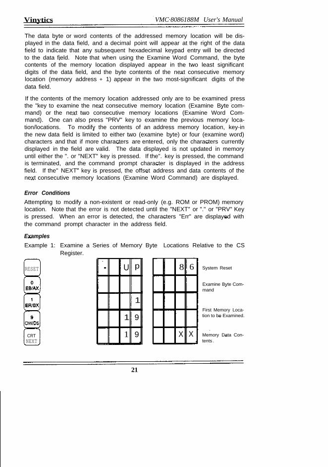
ExamplesExample 1: Examine a Series of Memory Byte Locations Relative to the CS
Register.
RESET . U p
·1·
1 9·
1 9CRTNEXT
8 6
X X .
System Reset
Examine Byte Com-mand
First Memory Loca-tion to be Examined.
Memory Data Con-tents .
21
VMC-8086/88M User's Manual Vinytics
1 A
1 8
1 C
-
x X
X X
X X .
Next Memory Loca-lion & Data Con-lents.Next Memory toea-tion & Dala Con-tents.Next Memory Loca-tion & Dala Con-tenls .
Command Termina-tion/Prompt.
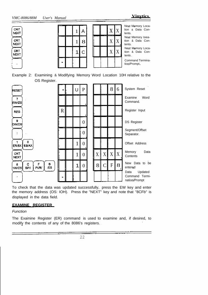
Example 2: Examining & Modifying Memory Word Location 10H relative to theOS Register.
- U P
R
0·0·
1 0
1 0
1 0·-
8 6
X X X X .8 C F 8
System Reset
Examine WordCommand.
Register Input
DS Register
Segment/OffsetSeparator.
Offset Address
Memory DataContents
New Data to beenteredData UpdatedCommand Termi-nation/Prompt
To check that the data was updated successfully, press the EW key and enterthe memory address (OS: IOH). Press the "NEXT" key and note that "8CFb" isdisplayed in the data field.
EXAMINE REGISTERFunction
The Examine Register (ER) command is used to examine and, if desired, tomodify the contents of any of the 8086's registers.
22
Vlnytica VMC·8086188M User's Manual
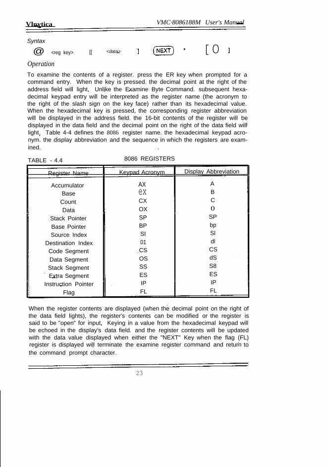
Syntax
@ <reg key> [[ <data> [0OperationTo examine the contents of a register. press the ER key when prompted for acommand entry. When the key is pressed. the decimal point at the right of theaddress field will light. Unlike the Examine Byte Command. subsequent hexa-decimal keypad entry will be interpreted as the register name (the acronym tothe right of the slash sign on the key face) rather than its hexadecimal value.When the hexadecimal key is pressed, the corresponding register abbreviationwill be displayed in the address field. the 16-bit contents of the register will bedisplayed in the data field and the decimal point on the right of the data field willlight. Table 4-4 defines the 8086 register name. the hexadecimal keypad acro-nym. the display abbreviation and the sequence in which the registers are exam-ined. .
TABLE - 4.4 8086 REGISTERS
Register Name Keypad Acronym Display Abbreviation
Accumulator AX ABase ex B
Count CX C
Data OX 0Stack Pointer SP SP
Base Pointer BP bpSource Index SI Sl
Destination Index 01 dlCode Segment CS CS
Data Segment OS dS
Stack Segment SS S8
Extra Segment ES ES
Instruction Pointer IP IP
Flag FL FL
When the register contents are displayed (when the decimal point on the right ofthe data field lights), the register's contents can be modified or the register issaid to be "open" for input. Keying in a value from the hexadecimal keypad willbe echoed in the display's data field. and the register contents will be updatedwith the data value displayed when either the "NEXT" Key when the flag (FL)register is displayed will terminate the examine register command and return tothe command prompt character.
23
VMC·8086188M User's Manual Vinytics
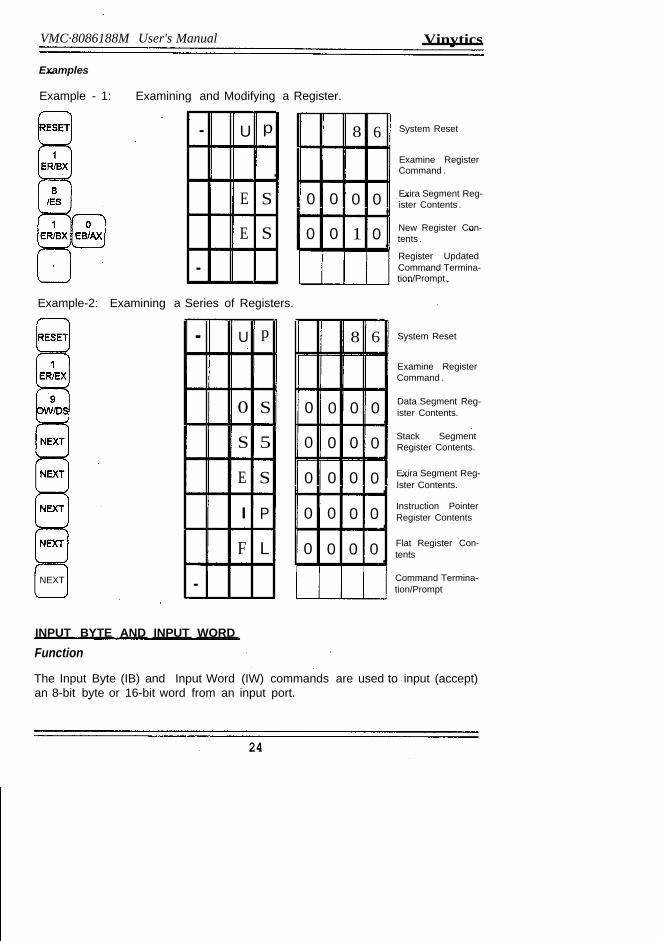
Examples
Example - 1: Examining and Modifying a Register.
- U p
.E S
E S
-Example-2: Examining a Series of Registers.
- U p
.0 S
S 5
E S
I P
F L
-NEXT
8 6
0 0 0 0 .0 0 1 0 .
8 6
0 0 0 0·0 0 0 0·0 0 0 0·0 0 0 0·0 0 0 0·
System Reset
Examine RegisterCommand .
Exira Segment Reg-ister Contents .
New Register Con-tents .
Register UpdatedCommand Termina-tion/Prompt.
System Reset
Examine RegisterCommand .
Data Segment Reg-ister Contents.
Stack SegmentRegister Contents.
Exira Segment Reg-Ister Contents.
Instruction PointerRegister Contents
Flat Register Con-tents
Command Termina-tion/Prompt
INPUT BYTE AND INPUT WORDFunction
The Input Byte (IB) and Input Word (IW) commands are used to input (accept)an 8-bit byte or 16-bit word from an input port.
24
Vinytics VMC·8086188M User's Manual
Syntax
@ <port addr> (NEXT)
@ <port addr> (NEXT)
Operation
To use either the Input Byte or Input Word command press the correspondinghexadecimal key when prompted for command entry. When either the IB or IWkey is pressed, the decimal point on the right of the address field will light toindicate that a port address entry is required. Using the hexadecimal keypad,enter the port address of the port to be read. Note that since I/O addressing islimited to 64 K (maximum address FFFFH), no segment value is permitted withthe port address.
.• oo..
After the port address has been entered, press the "NEXT" key. The input byteor word at the addressed port will be displayed in the data field. Again pressingthe "NEXT" key updates the data field display with the current data byte word atthe addressed input port. Pressing the "." key terminates the command andprompts for command entry.
The VMC-8603 includes three 8255A parallel I/O interface which can be usedwith the Input Bytes and Input Word commands to input data from peripheraldevices. Each 8255, in turn, consists of three individual 8-bit ports which aredesignated port A, Port B, and Port C. Each port operates independently duringbyte operations. During word operations, a pair of ports (l.e. a port of I and II8255 operate together to form the 16-bit wide data word with lind 8255 corre-sponding to the low order byte. The IIlrd 8255 can be used only for byteoperation and cannot be addressed in pair with some other port.
The Parallel I/O port circuits are programmed for input on power-up or wheneverthe system RESET key is pressed. If the circuit(s) previously has been pro-grammed for output press the system RESET key (before pressing the com-mand key) or, referring to the next section, output the appropriate byte or wordvalue to the circuit's control port to program the port(s) for input.
Example
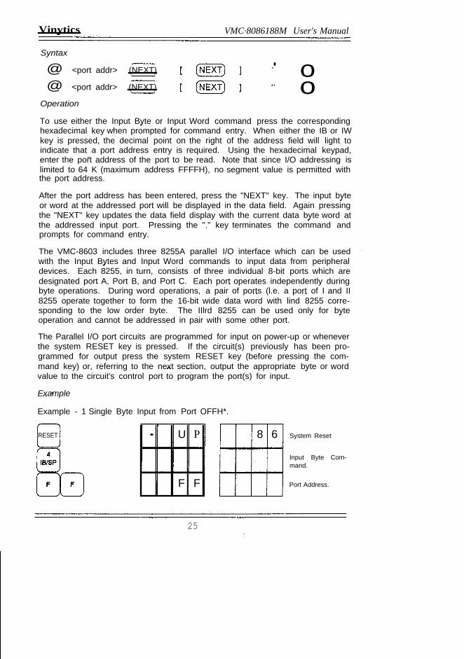
Example - 1 Single Byte Input from Port OFFH*.
RESET . U P
F F
8 6 System Reset
Input Byte Com-mand.
Port Address.
25
VMC.8086188M User's Manual Vinytics
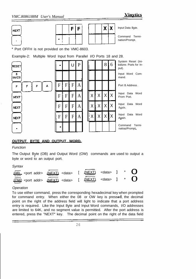
Input Data Byte.
Command Termi-nation/Prompt.
* Port OFFH is not provided on the VMC-8603.
Example-2: Multiple Word Input from Parallel I/O Ports 18 and 28.
. U P
.F F F A.F F F A
F F F A
F F F A
.
OUTPUT BYTE AND OUTPUT WORD
Function
The Output Byte (OB) and Output Word (OW) commands are used to output abyte or word to an output port.
Syntax
(08) <port addr> (NEXT) <data>
(OW) <port addr> (NEXT) <data>
8 6
X X X X
X X X X
X X X X
(NEXT) <data>
(NEXT) <data>
System Reset (Ini-tializes Ports for In-put).
Input Word Com-mand.
Port B Address .
Input Data WordFrom Port.
Input Data WordAgain.
Input Data WordAgain.
Command Termi·nation/Prompt.
* oo*
OperationTo use either command, press the corresponding hexadecimal key when promptedfor command entry. When either the 08 or OW key is pressed, the decimalpoint on the right of the address field will light to indicate that a port addressentry is required. Like the Input 8yte and Input Word commands, I/O addressesare limited to 64K, and no segment value is permitted. After the port address isentered, press the "NEXT" key. The decimal point on the right of the data field
26
V'my'tia VMC-8086/88M User's Manual
will light to indicate that the data byte or word to be output now can be entered.Using the keypad, enter the byte or word to be output. After the data is enteredpress the "." key to output the byte or word to the port and to terminate thecommand or press the "NEXT" key if additional data is to be output to theaddressed port.
As mentioned In the previous section, the Output Byte and Output Word com-mands can be used to program the 8255A parallel 1/0 port circuits for input oroutput as well as to output data to the individual ports. The 1/0 port circuits areprogrammed for input on power up or system reset and consequently first mustbe programmed for output (by outputting the appropriate data byte or word tothe circuit's control port) before data can be output to the associated ports..
Examples
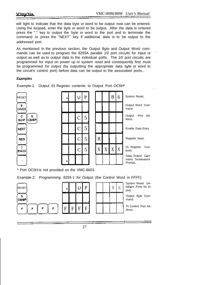
Example-1: Output 01 Register contents to Output Port OC5H*
RESET · U P
.C 5.C 5
C 5
C 5
·
8 6
.R .X X X X
System Reset.
Output Word Com-mand.
Output Port Ad-dress .
Enable Data Entry.
Register Input.
01 Register Con-tents.
Data Output, Com-mand TerminationlPrompt.
* Port OC5H is not provided on the VMC-8603.
Example-2: Programming 8255-1 for Output (the Control Word in FFFF).
RESET · U P
.F F F F .
8 6System Reset (ini-tializes Ports for In-put).
Output Byte Com-mand.
PI Control Port Ad-dress .
27
VMC-8086/88M User's Manual
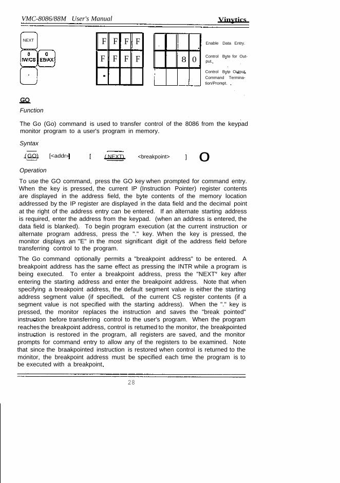
NEXT
Vinytics
F F F F
F F F F
.
GOFunction
8 0 .
Enable Data Entry.
Control Byte for Out-put.
Control Byte Output,Command Termina-tion/Prompt.
The Go (Go) command is used to transfer control of the 8086 from the keypadmonitor program to a user's program in memory.
Syntax
( GO) [<addr» ( NEXT) <breakpoint> oOperation
To use the GO command, press the GO key when prompted for command entry.When the key is pressed, the current IP (Instruction Pointer) register contentsare displayed in the address field, the byte contents of the memory locationaddressed by the IP register are displayed in the data field and the decimal pointat the right of the address entry can be entered. If an alternate starting addressis required, enter the address from the keypad. (when an address is entered, thedata field is blanked). To begin program execution (at the current instruction oralternate program address, press the "." key. When the key is pressed, themonitor displays an "E" in the most significant digit of the address field beforetransferring control to the program.
The Go command optionally permits a "breakpoint address" to be entered. Abreakpoint address has the same effect as pressing the INTR while a program isbeing executed. To enter a breakpoint address, press the "NEXT" key afterentering the starting address and enter the breakpoint address. Note that whenspecifying a breakpoint address, the default segment value is either the startingaddress segment value (if specifiedL of the current CS register contents (if asegment value is not specified with the starting address). When the "." key ispressed, the monitor replaces the instruction and saves the "break pointed"instruction before transferring control to the user's program. When the programreaches the breakpoint address, control is returned to the monitor, the breakpointedinstruction is restored in the program, all registers are saved, and the monitorprompts for command entry to allow any of the registers to be examined. Notethat since the braakpointed instruction is restored when control is returned to themonitor, the breakpoint address must be specified each time the program is tobe executed with a breakpoint.
28
Vinytics VMC·8086188M User's Manual
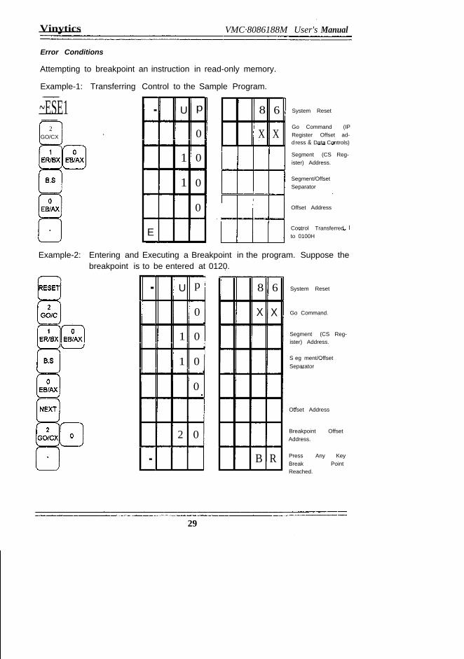
Error Conditions
Attempting to breakpoint an instruction in read-only memory.
Example-1: Transferring Control to the Sample Program.
~ESE12
GO/CX
. U p
0·1 0·1 0·0 ·
E
8 6
X X
System Reset
Go Command (IPRegister Offset ad-d ress & Data Controls)
Segment (CS Reg-ister) Address.
Segment/OffsetSeparator
Offset Address
Control Transferredto 0100H
Example-2: Entering and Executing a Breakpoint in the program. Suppose thebreakpoint is to be entered at 0120.
. U p
0·
1 0·
1 0·0
2 0
.
8 6
X X
B R
System Reset
Go Command.
Segment (CS Reg-ister) Address.
S eg ment/OffsetSeparator
Offset Address
Breakpoint OffsetAddress.
Press Any KeyBreak PointReached.
29
VMC.8086188M User's Manual Vinytics
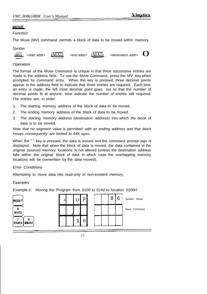
MOVEFunction
The Move (MV) command permits a block of data to be moved within memory.
Syntax
(MV) <start addr> (NEXT) <end addr> (NEXT) <destination addr> 0Operation
The format of the Move Command is unique in that three successive entries aremade in the address field. To use the Move Command, press the MV key whenprompted for command entry. When the key is pressed, three decimal pointsappear in the address field to indicate that three entries are required. Each timean entry is made, the left most decimal point goes out so that the number ofdecimal points lit at anyone time indicate the number of entries still required.The entries are, in order:
1. The starting memory address of the block of data to be moved.2. The ending memory address of the block of data to be moved.3. The starting memory address (destination address) into which the block of
data is to be moved.Note that no segment value is permitted with an ending address and that blockmoves consequently are limited to 64K bytes.
When the "." key is pressed, the data is moved and the command prompt sign isdisplayed. Note that when the block of data is moved, the data contained in theoriginal (source) memory locations is not altered (unless the destination addressfalls within the original block of data in which case the overlapping memorylocations will be overwritten by the data moved).
Error Conditions
Attempting to move data into read-only or non-existent memory.
Examples
Example-1: Moving the Program from 0100 to 014d to location 0200H
. U p
. . .1 0. . .
8 6 System Reset
Move Command .
30
Vinytics VMC-8086188M User's Manual
1 0. · ·0. · ·
· ·4 0· ·
·2 0 ·2 0 ·
0
.
NEXT
2 0Go/ex EB/AX
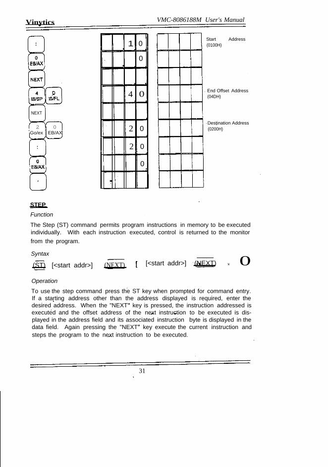
STEPFunction
Start Address(0100H)
End Offset Address(04DH)
Destination Address(0200H)
The Step (ST) command permits program instructions in memory to be executedindividually. With each instruction executed, control is returned to the monitorfrom the program.
Syntax
(ST) [<start addr>] (NEXT) [<start addr>] (NEXT) w 0Operation
To use the step command press the ST key when prompted for command entry.If a starting address other than the address displayed is required, enter thedesired address. When the "NEXT" key is pressed, the instruction addressed isexecuted and the offset address of the next instruction to be executed is dis-played in the address field and its associated instruction byte is displayed in thedata field. Again pressing the "NEXT" key execute the current instruction andsteps the program to the next instruction to be executed.
31
VMC.8086188M User's Manual Vinytic:s
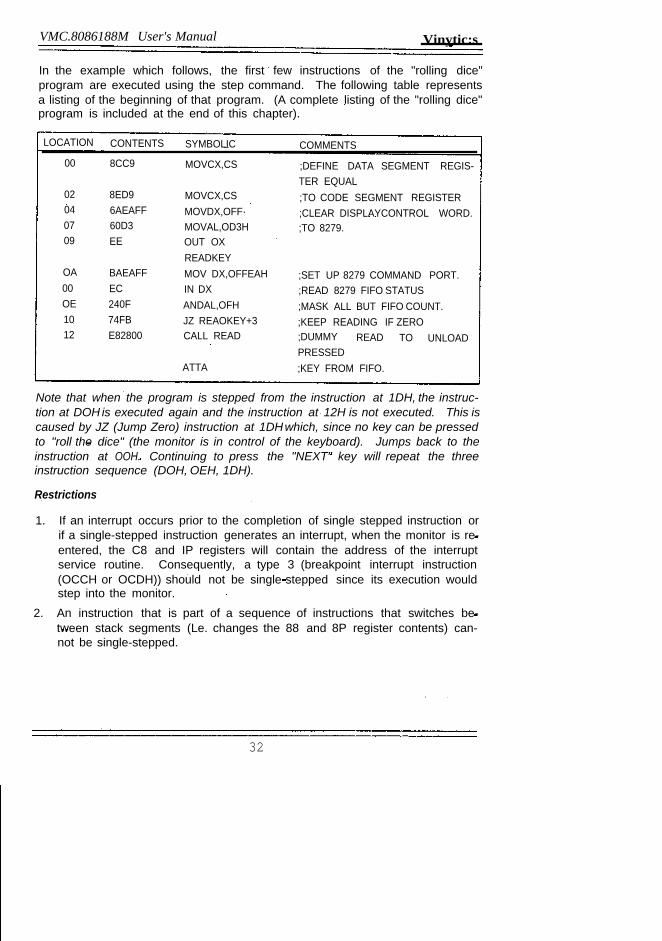
In the example which follows, the first few instructions of the "rolling dice"program are executed using the step command. The following table representsa listing of the beginning of that program. (A complete listing of the "rolling dice"program is included at the end of this chapter).
LOCATION CONTENTS SYMBOLIC COMMENTS
00 8CC9 MOVCX,CS ;DEFINE DATA SEGMENT REGIS-TER EQUAL
02 8ED9 MOVCX,CS ;TO CODE SEGMENT REGISTER04 6AEAFF MOVDX,OFF· ;CLEAR DISPLAYCONTROL WORD.07 60D3 MOVAL,OD3H ;TO 8279.09 EE OUT OX
READKEYOA BAEAFF MOV DX,OFFEAH ;SET UP 8279 COMMAND PORT.00 EC IN DX ;READ 8279 FIFO STATUSOE 240F ANDAL,OFH ;MASK ALL BUT FIFO COUNT.10 74FB JZ REAOKEY+3 ;KEEP READING IF ZERO12 E82800 CALL READ ;DUMMY READ TO UNLOAD
PRESSEDATTA ;KEY FROM FIFO.
Note that when the program is stepped from the instruction at 1DH, the instruc-tion at DOH is executed again and the instruction at 12H is not executed. This iscaused by JZ (Jump Zero) instruction at 1DHwhich, since no key can be pressedto "roll the dice" (the monitor is in control of the keyboard). Jumps back to theinstruction at OOH. Continuing to press the "NEXT" key will repeat the threeinstruction sequence (DOH, OEH, 1DH).
Restrictions
1. If an interrupt occurs prior to the completion of single stepped instruction orif a single-stepped instruction generates an interrupt, when the monitor is re-entered, the C8 and IP registers will contain the address of the interruptservice routine. Consequently, a type 3 (breakpoint interrupt instruction(OCCH or OCDH)) should not be single-stepped since its execution wouldstep into the monitor.
2. An instruction that is part of a sequence of instructions that switches be-tween stack segments (Le. changes the 88 and 8P register contents) can-not be single-stepped.
32
Vinytics
Examples
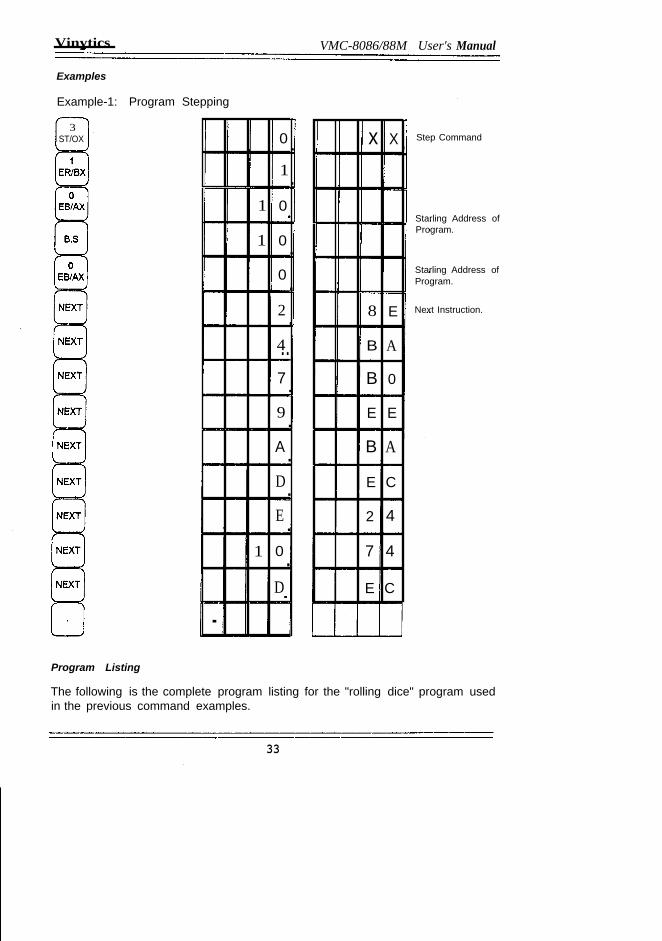
Example-1: Program Stepping
3ST/OX 0·
1·1 0
1 0·0·2·4..7·9·A·D·E·
1 0·D
.
VMC-8086/88M User's Manual
x X .
8 E
B A
B 0
E E
B A
E C
2 4
7 4
E C
Step Command
Starling Address ofProgram.
Starling Address ofProgram.
Next Instruction.
Program Listing
The following is the complete program listing for the "rolling dice" program usedin the previous command examples.
33
VMC.80/J.(}188M User's Manual Vmytics
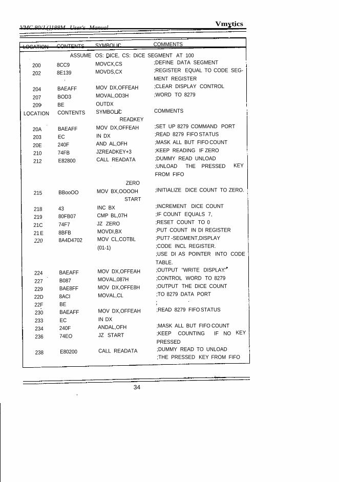
LOCATION CONTENTS SYMBOLIC COMMENTS
ASSUME OS: DICE, CS: DiCE SEGMENT AT 100
200 8CC9 MOVCX,CS ;DEFINE DATA SEGMENT
202 8E139 MOVDS,CX ;REGISTER EQUAL TO CODE SEG-MENT REGISTER
204 BAEAFF MOV DX,OFFEAH ;CLEAR DISPLAY CONTROL
207 BOD3 MOVAL,OD3H ;WORD TO 8279
209 BE OUTDX
LOCATION CONTENTS SYMBOLIC COMMENTSREADKEY
20A BAEAFF MOV DX,OFFEAH ;SET UP 8279 COMMAND PORT
203 EC IN DX ;READ 8279 FIFO STATUS
20E 240F AND AL,OFH ;MASK ALL BUT FIFO COUNT
210 74FB JZREADKEY+3 ;KEEP READING IF ZERO
212 E82800 CALL READATA ;DUMMY READ UNLOAD;UNLOAD THE PRESSED KEYFROM FIFO
ZERO
215 BBooOO MOV BX,OOOOH ;INITIALIZE DICE COUNT TO ZERO.
START
218 43 INC BX ;INCREMENT DICE COUNT
219 80FB07 CMP BL,07H ;IF COUNT EQUALS 7,
21C 74F7 JZ ZERO ;RESET COUNT TO 0
21 E 8BFB MOVDI,BX ;PUT COUNT IN DI REGISTER
220 8A4D4702 MOV CL,COTBL ;PUT7 -SEGMENT,DISPLAY
(01-1) ;CODE INCL REGISTER.;USE DI AS POINTER INTO CODETABLE.
224 BAEAFF MOV DX,OFFEAH ;OUTPUT "WRITE DISPLAY"
227 B087 MOVAL,087H ;CONTROL WORD TO 8279
229 BAE8FF MOV DX,OFFE8H ;OUTPUT THE DICE COUNT
22D 8ACI MOVAL,CL ;TO 8279 DATA PORT
22F BE230 BAEAFF MOV DX,OFFEAH ;READ 8279 FIFO STATUS
233 EC IN DX
234 240F ANDAL,OFH ;MASK ALL BUT FIFO COUNT
236 74EO JZ START ;KEEP COUNTING IF NO KEY
PRESSED
238 E80200 CALL READATA ;DUMMY READ TO UNLOAD;THE PRESSED KEY FROM FIFO
34
Vinytics VMC-8086188M User's Manual
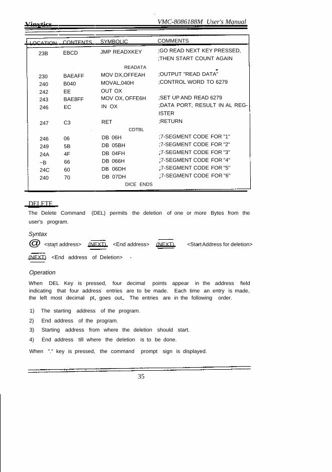
LOCATION CONTENTS SYMBOLIC COMMENTS
23B EBCD JMP READXKEY ;GO READ NEXT KEY PRESSED,;THEN START COUNT AGAIN
READATA -230 BAEAFF MOV DX,OFFEAH ;OUTPUT "READ DATA"
240 B040 MOVAL,040H ;CONTROL WORD TO 6279
242 EE OUT OX243 BAE8FF MOV OX, OFFE6H ;SET UP AND READ 6279
246 EC IN OX ;DATA PORT, RESULT IN AL REG-ISTER
247 C3 RET ;RETURNCDTBL
246 06 DB 06H ;7-SEGMENT CODE FOR "1"
249 5B DB 05BH ;7-SEGMENT CODE FOR "2"
24A 4F DB 04FH ;7-SEGMENT CODE FOR "3"
~B 66 DB 066H ;7-SEGMENT CODE FOR "4"
24C 60 DB 06DH ;7-SEGMENT CODE FOR "5"
240 70 DB 07DH ;7-SEGMENT CODE FOR "6"DICE ENDS
DELETEThe Delete Command (DEL) permits the deletion of one or more Bytes from theuser's program.
Syntax
@ <start address> (NEXT) <End address> (NEXT) <StartAddress for deletion>
(NEXT) <End address of Deletion>
Operation
When DEL Key is pressed, four decimal points appear in the address fieldindicating that four address entries are to be made. Each time an entry is made,the left most decimal pt. goes out. The entries are in the following order.
1) The starting address of the program.
2) End address of the program.
3) Starting address from where the deletion should start.
4) End address till where the deletion is to be done.
When "." key is pressed, the command prompt sign is displayed.
35
VMC·8086188M User's Manual Vinytia
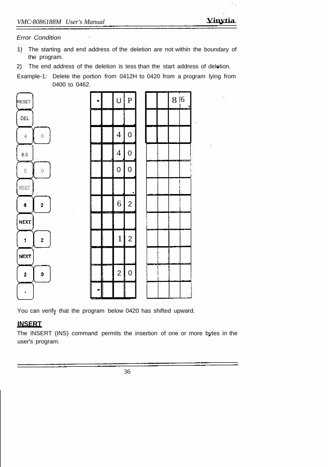
Error Condition
1) The starting and end address of the deletion are not within the boundary ofthe program.
2) The end address of the deletion is tess than the start address of deletion.
Example-1: Delete the portion from 0412H to 0420 from a program lying from0400 to 0462.
RESET . U P
· · · ·4 0
· · · ·4 0· · · ·0 0
· · · ·· ·6 2
· · ·· ·1 2· ·
·2 0·.
DEL
4 0
B.S
o 0
NEXT
8 '6I .
.
You can verify that the program below 0420 has shifted upward.
INSERTThe INSERT (INS) command permits the insertion of one or more bytes in theuser's program.
36
Vinytics VMC.8086188M User's Manual=
Syntax
@ <start address> ( NEXT) <End address> (NEXT)
<address from which Insertion is to be done> (NEXT)
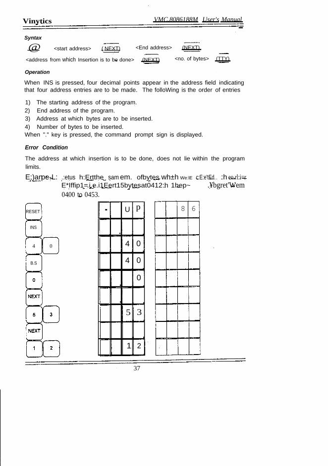
Operation
When INS is pressed, four decimal points appear in the address field indicatingthat four address entries are to be made. The folloWing is the order of entries
<no. of bytes> (TTY)
1) The starting address of the program.2) End address of the program.3) Address at which bytes are to be inserted.4) Number of bytes to be inserted.When "." key is pressed, the command prompt sign is displayed.
Error Condition
The address at which insertion is to be done, does not lie within the programlimits.
E;)anpe-L: .:etus h:Ertthe sam em. ofbytes wh±h We:lE c:E:e'tEd. :h eo.rl:i=rE*Iffip1=.i.e.i1Eert15bytesat0412:h 1hep~ .¥bgret'Wem0400 to 0453.
4 0
. U p
· · ·4 0
· · · ·4 0
· · · ·0
· · ·· ·5 3· · ·· ·
1 2· ·
8 6RESET
INS
B.S
37
VMC-8086188M User's Manual Vinytics
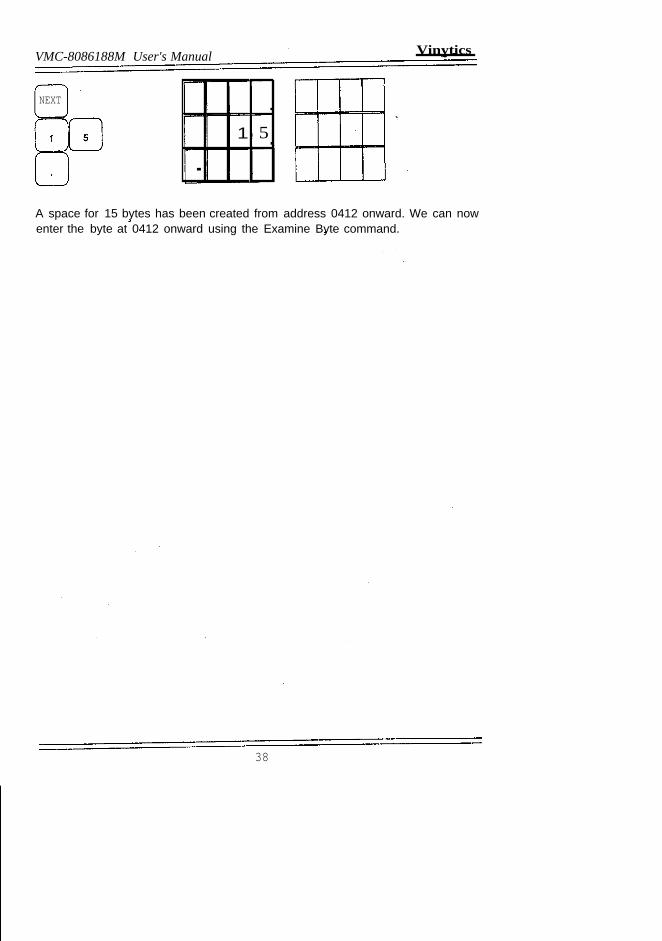
NEXT .1 5.
.
A space for 15 bytes has been created from address 0412 onward. We can nowenter the byte at 0412 onward using the Examine Byte command.
38
ON BOARD INTERFACES
GENERAL DETAILS OF INTERFACESTo enhance the capabilities of the system on board interfaces for RS-232-C andEPROM Programmer have been provided. Most of the CRT terminals provideR5-232-C and (0-20mA) loop interface and so a CRT terminal can be con-nected to it through any of the two standard interfaces. The R5-232-C providedthrough Intel's 8251A (U5ART).
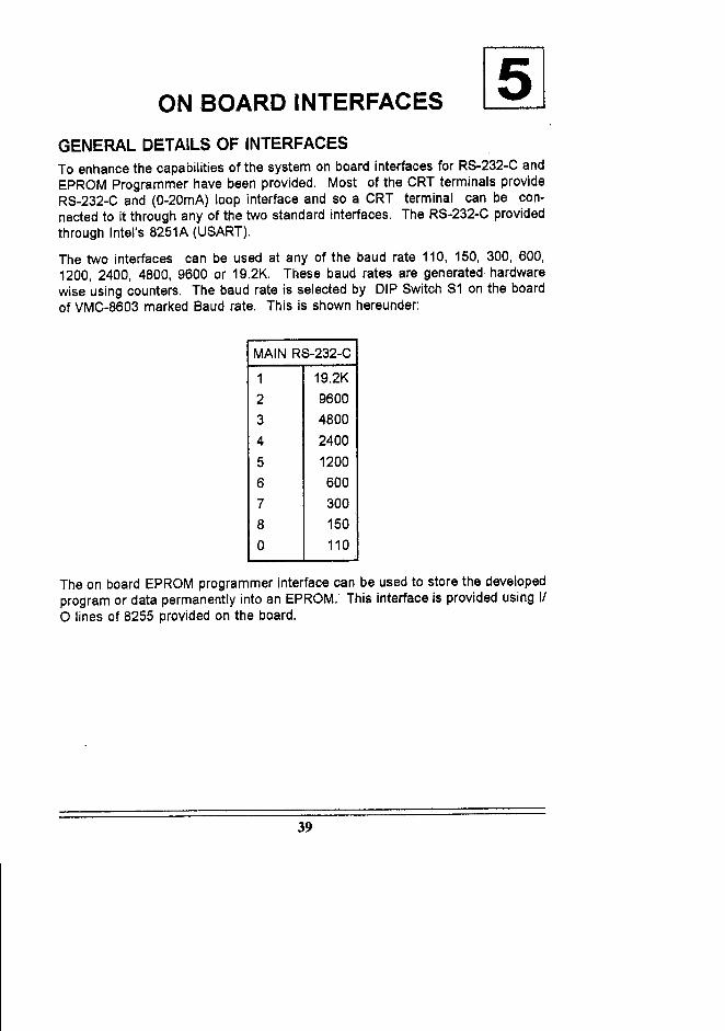
The two interfaces can be used at any of the baud rate 110, 150, 300, 600,1200, 2400, 4800, 9600 or 19.2K. These baud rates are generated hardwarewise using counters. The baud rate is selected by DIP Switch 51 on the boardof VMC-8603 marked Baud rate. This is shown hereunder:
MAIN R5-232-C
1 19.2K2 96003 48004 24005 12006 6007 3008 1500 110
The on board EPROM programmer interface can be used to store the developedprogram or data permanently into an EPROM. This interface is provided using IIo lines of 8255 provided on the board.
39
VMC·8086188M User's Manual Vinytics
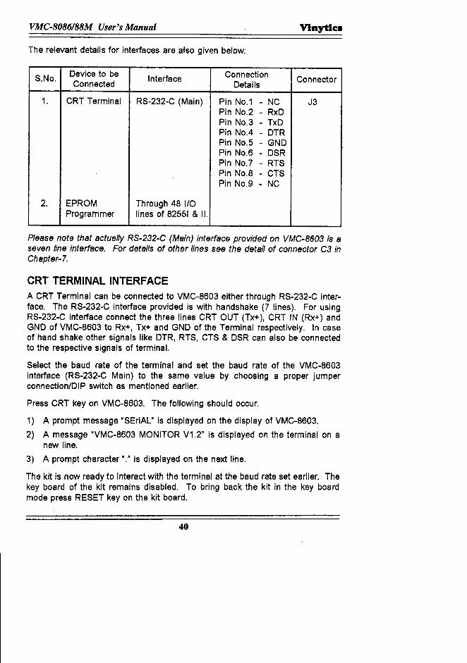
The relevant details for interfaces are also given below:
S.No. Device to be Interface Connection ConnectorConnected Details
1. CRT Terminal RS-232-C (Main) Pin NO.1 - NC J3Pin NO.2 - RxDPin NO.3 - TxDPin NO.4 - DTRPin NO.5 - GNDPin NO.6 - DSRPin NO.7 - RTSPin NO.8 - CTSPin NO.9 - NC
2. EPROM Through 48 I/OProgrammer lines of 82551 & II.
Please note that actually RS-232-C (Main) interface provided on VMC-8603 is aseven line interface. For details of other lines see the detail of connector C3 inChapter-7.
CRT TERMINAL INTERFACEA CRT Terminal can be connected to VMC-8603 either through RS-232-C inter-face. The RS-232-C interface provided is with handshake (7 lines). For usingRS-232-C interface connect the three lines CRT OUT (Tx+), CRT IN (Rx+) andGND of VMC-8603 to Rx+, Tx+ and GND of the Terminal respectively. tn caseof hand shake other signals like DTR, RTS, CTS & DSR can also be connectedto the respective signals of terminal.
Select the baud rate of the terminal and set the baud rate of the VMC-8603interface (RS-232-C Main) to the same value by choosing a proper jumperconnection/DIP switch as mentioned earlier.
Press CRT key on VMC-8603. The following should occur.
1) A prompt message "SEriAL" is displayed on the display of VMC-8603.2) A message "VMC·8603 MONITOR V1.2" is displayed on the terminal on a
new line.3) A prompt charaoter "." is displayed on the next line.
The kit is now ready to interact with the terminal at the baud rate set earlier. Thekey board of the kit remains disabled. To bring back the kit in the key boardmode press RESET key on the kit board.
40
Vinytics VMC·8086188M User's Manual
EPROM PROGRAMMERVMC-8603 provides onboard EPROM PROGRAMMER for the 2764/27128/27256EPROMS. The following commands can be used in the EPROM-Programmermode.
1) BLANK CHECK2) LIST3) VERIFY4) PROGRAM (DUPLICATE)
Since 8086 is a 16 bit processor and the memory chips available are of 8 bits,the odd and even bytes of 16 bit Data have to be separated out. And so whileusing list, verify and program command, the user should specify whether theoperation is to be done on odd bytes or even bytes or continuous bytes. This isdone by using different terminators for the Commands.
a '0' is used as a terminator for continuous Bytes.a '1' is used as a terminator for odd Bytes.a '2' is used as a terminator for even Bytes.
The 20 bit address of BOB6 is divided into two parts, the segment address andthe offset address. The starting address of any EPROM in the ZIF socket is0000 and the rnaxlrnurn address will depend upon the capacity of the chip. Incase of 27128 chip, the maximum address would be 3FFF. The address of theEPROM in the ZIF is also divided into segment address and offset address. Inthis case the segment address should be always given as 0000 followed by theoffset address which would be the actual address. In case of LIST, VERIFY &PROGRAM Commands, three addresses are to be entered. Two addressescorrespond to the memory on the board of VMC-8603 and the third addresscorrespond to the EPROM in the ZIF socket.
It is important to note that in case of the Even Byte operation, the two addressescorresponding to the Board of VMC·B603 should both be even addresses and incase of the Odd Byte operation, both the addresses should be odd addresses. Adeviation from above i.e, a combination of Even and Odd address with theterminator as 1 or 2 would result in Error condition and in this case, the com-mand does not terminate at all unless Reset Key is pressed.
BLANK CHECK
Blank check command is used to check the EPROM placed in the ZIF (ZeroInsertion Force) socket for blank.
41
VMC.8086188M User's Manual Vinytics
Syntax
(BC/IP) <start address> <End address>
Operation
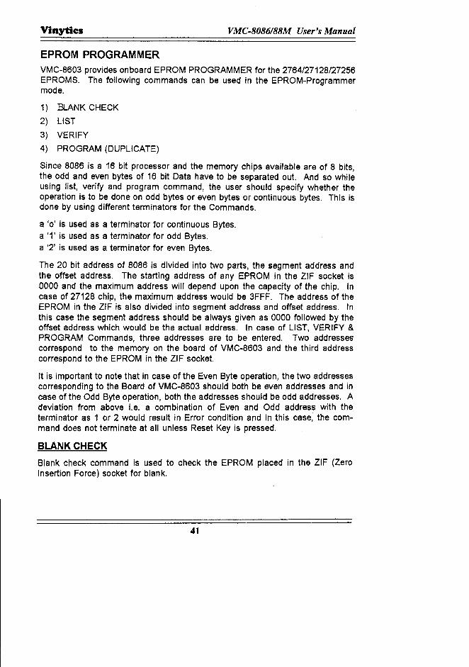
When BC Key is pressed, two decimal points appear in the address field toindicate that two address entries are required. Each time an entry is made, theleft most decimal point goes out. The entries are in order
1) The starting addressof the EPROM from where the blank checkshould start.2) The End addressof the EPROM till wtlere the system shouldcheck for blank.Blank check can be performed on 2764/27128/27256. Please see the note at theend of this chapter.
When the "." key is pressed, the command prompt sign "." is displayed if theEPROM area being checked is blank. If any location is not blank, its addresswill be displayed in the address field and its contents in the data field. If this isthe only location which is not blank, then on pressing NEXT key, the commandprompt sign will appear otherwise the address of the next location which is notblank will be displayed and so on.
Example-1: Perform a blank check on a blank 2764 EPROM (entire 8K).
RESET . U p
. ·0. ·
I F F F·.
8 6
VERIFYThis command is used to verify the content of the EPROM put in the ZIF Socketwith any memory area on the board of VMC-86/3 (RAM OR ROM). Please seethe note at the end of this chapter.
42
Vinytic:a VMC·8086188M User's Manual
Syntax
(V~/J <start address of onboard memory:{NEXT)
<end address of onboard memory> (NEXT)
<start address of EPROM IN ZIF> (NEXl)
Operation
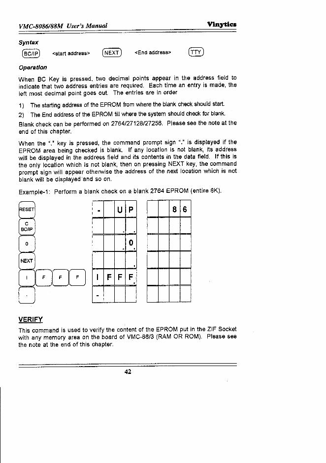
On pressing VR key, three decimal points will appear in the address field indicat-ing that 3 addresses are required to be entered. The entries are to be made inthe following order:
1) Starting address of the memory block on VMC-8603 with which the contentsof the EPROM in the ZIF is to be verified.
2) End address of the memory block on VMC-8603.3) Starting address of the EPROM in the ZIF socket. When '0', '1' or '2' key is
pressed, the two blocks of memory are verified for equality. If they areequal, the command prompt sign is displayed. If they are not equal, theaddress at which the discrepancy occurs and its contents are displayed. Ifthis is the only location where the discrepancy exist, a command promptsign is displayed on pressing NEXT key otherwise, the next location addresswhere there is a difference will be displayed.
Example-1: Verify the contents of 2764 EPROM from location 0100 to 0120(Even Byte) with the Monitor of VMC-8603 starting from FCOOOtoFC040. We assume that the two blocks are not same and there is adiscrepancy at FC006 and FC008.
NEXT
. U p
. ·F C 0 0
· ·F C 0 0. ·
0. · ·· .
RESET 8 6
43

VMC·8086188M User's Manual VinytiCil
4 0. ·
·0·
0·0 1 0 0
·0 1 0 0
0 1 0 6·0 1 0 8
.NEXT
x X
X X .
The add resses atwhich the datacontents are notequal.
LISTThis command is used to list the contents of an EPROM in the ZIF socket, in thesystem RAM area. Please see the note at the end of this chapter.
Syntax
@ <start address> (NEXT) <end address of RAM> (NEXT)
<start address of EPROM> (NEXT)
Operation
On pressing LS key, three decimal points are displayed in the address fieldindicating that three addresses are required to be entered. The entries are to bemade in the following order.
1) Starting address of the RAM where the listing is to be made.2) End address of the RAM where the listing is to be made.3) Starting address of the EPROM in the ZIF socket from where the listing is to
be made in the RAM area.
44
Vinytics VMC-S086/88M User's Manual
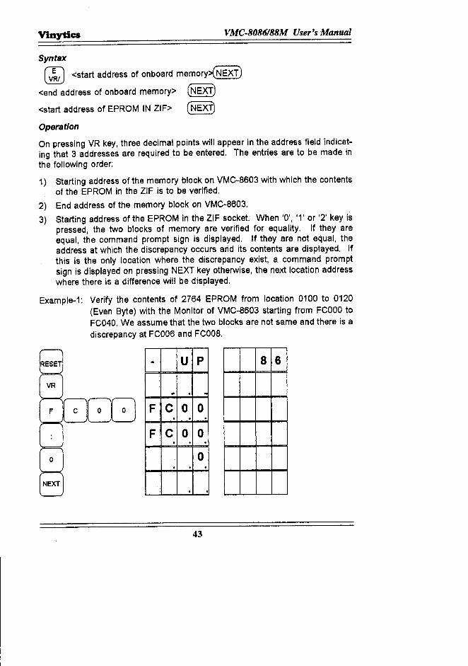
On pressing '0' or '1' or '2' key, the command prompt character is displayed.
Example-1: LIST the contents of EPROM 2764 from 0200 in to RAM area 00500to 00525 (Continuous Bytes).
NEXT
5 52
NEXT
o
. U p
·0. ·0. ·
5 0 0. . ··
5 2 5··
0·0·
2 0 0·
2 0 0·
8 6
.
PROGRAMThis command is used to program any of the earlier mentioned EPROM with thedata lying any where on the board of VMC-8603 (ROM or RAM). Please see thenote at the end of this chapter.
45

VMC-8086/88M User's Manual Vinytics
Syntax
(PRG) <starting address of onboard memory> (NEXT)
<End address of onboard memory> (NEXT)
<starting address of EPROM on ZIF> (NEXT)
Operation
On pressing PRG Key, three decimal points are displayed in the address fieldindicating that three address entreis are to be made. The entries are to be madein the following order.
1) Starting address of the onboard memory from where the data is to be taken.2) End address of the onboard memory till where the data is to be taken.3) Starting address of the EPROM in the ZIF socket from where the program-
ming should start.
On pressing 'O'or'1'or'2'key, the programming will start. This is indicated byblinking PRG IND LED. When the programming is over, a command promptcharacter is displayed in the address field.
Example-1: Program 2732 EPROM with the EPROM lying in VMC-8603 at theaddress FEOOOto FFFFF (continuous Byte)
NEXT
. U p
· · ·F E 0 0
· ·F E 0 0
· · ·0· · ·
· ·F F F
· ··
8 6
46
VinytiCII VMC.8086188M User's Manual
0·0·
0·
0·.
Note 1. Before performing any of the EPROM Programmer Commands,ensure that the required Personality module has been put in thesocket respectively.
2. BeDle PICXJ!aIUUbJ, re pbk w:ite afire p:MTerCI:ll"lMdDr C6)S'nilire ci:nra:ierl ao:n:rdtg to ire~bJ\Olag= li:q.Iis:inrre EPROM.
EPROM276427C642712827C1282725627C25627162732
21V12.5V21V12.5V21V12.5V25V21V
*(Programming Voltage isseleoted by switch givenat the back in the modelVMC-8603P)
* For all CMOS (27C .... ) EPROMs it is 12.5V only.
3. Notch should point in the upper direction, base to be fixed at PinNo.14 (GND).
- 28
14 1....-__ ---1 15
47
SERIAL I/O DEVICECOMMANDS
GENERALIt has been mentioned earlier that the VMC-8603 can be connected to serialdevices like Teletypewriter or CRT Terminal through 20mA current loop or RS-232-C interface. User can enter in the serial mode from the keyboard of VMC·8603 using TTY key or CRT key depending upon which serial interface is beingused,
On entering into serial mode a prompt message "SEriAL" is displayed on theaddress and Data field of VMC-8603 DISPLAY. ("SEri" is displayed in theaddress field and "AL" is displayed on the data field), At the same time amessage "VMC-8603 MONITOR V1.2" is displayed on the serial device on oneline and a prompt character "." on the next line to indicate that it is ready toaccept command entry.
This line is referred to as the "command line" and consists of either a one-or-two-character command mnemonic followed by one to three command param-eters or "arguments". (If desired for visual separation, a space can be enteredbetween the command mnemonic and the first argument). When more thanone argument is required, a single comma (",") is used between arguments as adelimiter.
A command line is terminated either by a carriage return or a comma, dependingon the command itself. Commands are executed one at a time and only onecommand is permitted within a command line.
With the exception of the register abbreviations associated with the X (Examine!Modify Register) command, all arguments are entered as hexadecimal numbers.The valid range of hexadecimal values is from 00 to FF for byte entries and from0000 to FFFF for word entries (leading zero's may be omitted). If more than two(byte entries) or four (word entries) digits are entered; only the last two or fourdigits entered are valid. Address arguments consist of segment value & anoffset value. If a segment value is not entered, the default segment value is thecurrent contents of the code segment (CS) register unless specified otherwise inthe command description. When both a segment value and an offset value areentered as an address argument, entry is the offset value. A colon (":") isentered the first entry is the segment value, and the second between the entreisas a separator.
Since command execution occurs only after a command terminator is entered, •command entry can be cancelled any time before the terminator is entered bypressing any character that is not legal for the entry expected. When a com-mand is cancelled, the number symbol ('#') is output on the command line, ac:ard3.geJEtr.nn an:l a :Ib= Ee:i alE i:s..Hi an:l1he canm an:l prm pt chnad:er~':1is oo1pJtm ih= new Jhe.
49
VMC.8086188M User's Manual V'mytics
XTALK is a simple terminal emulator software for IBM-PC/XT/AT compatiblecomputers. It allows the user to communicate with the computer through serialport with the facility of downloading & uploading of the data between the com-puter and the other serial devices. The various communication parameters likebaud rate (speed), number of data bits, stop bits, parity etc. can be changed.The package communicates through COM1: as well as COM2: ports of the IBM·PC/XT/AT system.
INSTALLATIONa) Insert the diskette containing XTALK in your A: drive.b) If you have hard disk, make a directory in the name of XTALK in your c:
drive.c) Copy the diskette in your directory as given below:
A> COpy «: C:\XTALK <CR>d) Execute XTALK as given below:
XTALK <CR> (either from A: or C:)
SECTION OF COMMUNICATION PARAMETERSFor setting the parameters, press <HOME> key. The system will show you a'COMMAND? Prompt which means that the system is asking you to give com-mands. Write 'SP-9600' to set the baud rate at 9600.
COMMAND? SP 9600
The baud rates available in XTALK are: 110, 150,300,600, 1200, 2400, 4800,9600, 19200 etc. If you want to set the baud rate at say 4800, then in "COM-MAND?" Prompt, write SP-9600 and press <CR>, Rest of the parameters viz.Parity, Duplex Mode, Data Parity, Full Duplex Mode, 8 Data Bits and one StopBit. If you want to change any of the parameters write the first two letters e.g.,'PA for Parity, 'DU' for Duplex Mode and then write as per requirement. Supposeyou want to change Parity, you should write in the COMMAND? Prompt PAEVEN, for odd Parity write PA ODD. Similarly one can change Duplex mode,Port etc.After setting the parameters, write GO LO in COMMAND? Prompt. It will showyou that "Local data link is now active. Press <CR:>and on screen you will get aprompt to start with.
COMMUNICATION BETWEEN XTALK SOFTWARE & VMC·8603
KITa) Connect the Kit and Power Supply. Make sure that the +5V, GND, +12V & -
12V are connected properly.b) Connect the serial port of PC with the RS-232-C (9 pin connector) of the kit.
50
Vinyties VMC·8086188M User's Manual
g) Your PC & Kit are now linked for communication and all your instructionscan now be operated from your PC Keyboard.
All serial commands mentioned in this chapter will be fed through PC Keyboard.Uploading & Downloading can also be done through this Kit.
NOTE: The standard buffers used in RS232C interface are 1488 and 1489 IC's.In case of any problem in serial communication, one scan suspect thesegoing bad. The RS232C port also does not work in case of failure of+12V or -12V supply. The voltages can be checked at pin NO.1 of IC1488 and pin NO.14 of Ie 1488 to be -12V and +12V respectively withrespect to ground.
LIST OF MONITOR COMMANDSVMC-8603 serial monitor is capable of executing the following commands:
1) Substitute Memory (S)2) Examine/Modify Register (X)3) Display Memory (D)4) Move (M)5) Port Input (I)6) Port Output (0)7) GO (G)
8) Single Step (N)9) Read Hex file (R)10) Write Hex file (W)11) Uploading Data (W Starting Address , ~nding Address)
12) Downloading Data (R)
While explaining the commands the follOWingsyntax is used:
[Aj indicates that "A" is optional[Aj· indicates one or more occurrences of "An<B> indicates that "B" is a variable<Cr> indicates that a carriage return is entered.
51
VMC-8086/88M User's Manual Vinytics
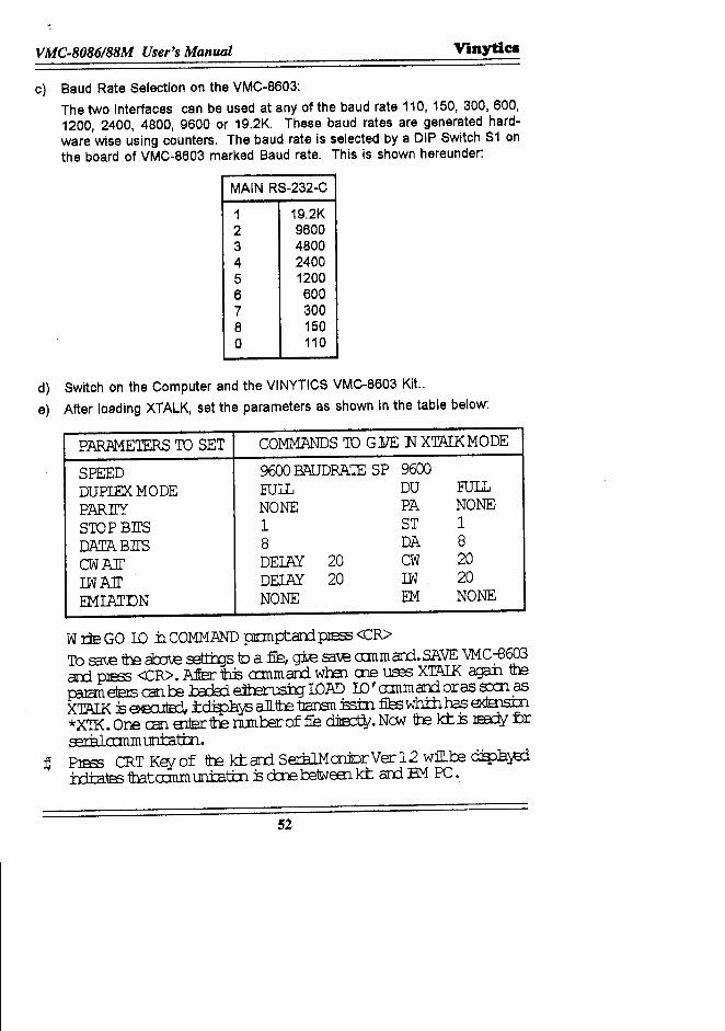
c) Baud Rate Selection on the VMC-8603:The two interfaces can be used at any of the baud rate 110, 150, 300,600,1200, 2400, 4800, 9600 or 19.2K. These baud rates are generated hard-ware wise using counters. The baud rate is selected by a DIP Switch S1 onthe board of VMC-8603 marked Baud rate. This is shown hereunder:
MAIN RS-232-C
1 19.2K2 96003 48004 24005 12006 6007 3008 1500 110
d) Switch on the Computer and the VINYTICS VMC-8603 Kit..e) After loading XTALK, set the parameters as shown in the table below:
PARAMETERS TO SET COMMANDS TO GYE 1'1 XTAIKMODE
SPEED 9600 BAUDRA'IE 5P 9600DUPIEXMODE FULL DU FUlLPARTIY NONE PA NONESTOP BII'5 1 5T 1DATABII'S 8 DA 8CWAll' DEIAY 20 CW 20IW All' DEIAY 20 I.W 20EMIATDN NONE EM NONE
WrleGO IO ±lCOMMAND pn:mptard.plEH3<CR>To S3.-U:: re al:xJ\e ~ 10 a fie, gie S3.-U:: crmmard..SAVE VMC-8603ard. plESS <CR>. Mer 1h:Bcrmm ard when ere uses XTIUK agaiJ. repezan etErs can be 1:.ada:ie:irerus:b:;r IOAD ID' rrmmard eras s:x:n asXTAlK 13ea:uta:l, .tc:ti:p}iys allfre tJansn:5stn :ties wh±h has 6<IEnstn*XTK. One can Enterre runteroffie d:ia::rl¥. New re kt13 lEEdy Drs:rilia:mmuntattn.
~ PleSS CRT Key of re k±:ard. 5eriilMmilDrVer12 w:ill.re dEpJ3.y;rlirltatB3 1batcrmm mi:attn 13d::n= retwe:n kt ard EMPC.
52
Vinytics VMC.8086188M User's Manual
COMMAND DESCRIPTIONSUBSTITUTE MEMORYFunction
The substitute Memory (S) command is used to examine the byte (S) or word(SW) contents of select memory locations. If the contents of the memorylocation can be modified (e.g., a RAM location), the contents additionally can beupdated with a neWdata value entered from the console device.
Syntax
S [W] <ADDR>, [[ <NEW CONTENTS> ], r <CR>
Oporatlon
To use the Substitute Memory command, enter S or SW when prompted com-mand entry and enter the address of the memory location to be examined. Noteif a segment address value is not specified, the current contents of the codesegment (CS) register are used by default. After the address is entered, enter acomma. The monitor location followed by a dash (the monitor's data entryprompt character) and a space to indicate that the addressed location is open forupdate. Note that when using the SW command, the byte contents of the nextconsecutive memory location (memory address + 1) are outputted first, followedby the byte contents of the actual location addressed. Similarly, when updatingmemory contents using the SW command, first the next consecutive memorylocation, and the second byte entry (next two digits) will be written into theaddressed memory location.
If only one memory location is to be examined enter a carriage return to termi-nate the command. (If new data was entered, it is updated when the carriagereturn is entered). If a series of continuous memory locations are to be exam-ined and/or updated, enter a comma to advance to the next consecutive memorylocation (S Command) or next two consecutive memory locations (SW com-mand). Again, if the data contents are not to be updated, enter a comma toexamine the next memory location or enter the new data followed by a comma toupdate the current location and to examine the next location. Entering a carriagereturn terminates the command.
Error ConditionsAttempting to modify a non-existent or read-only (e.goo,ROM or PROM) memorylocation.
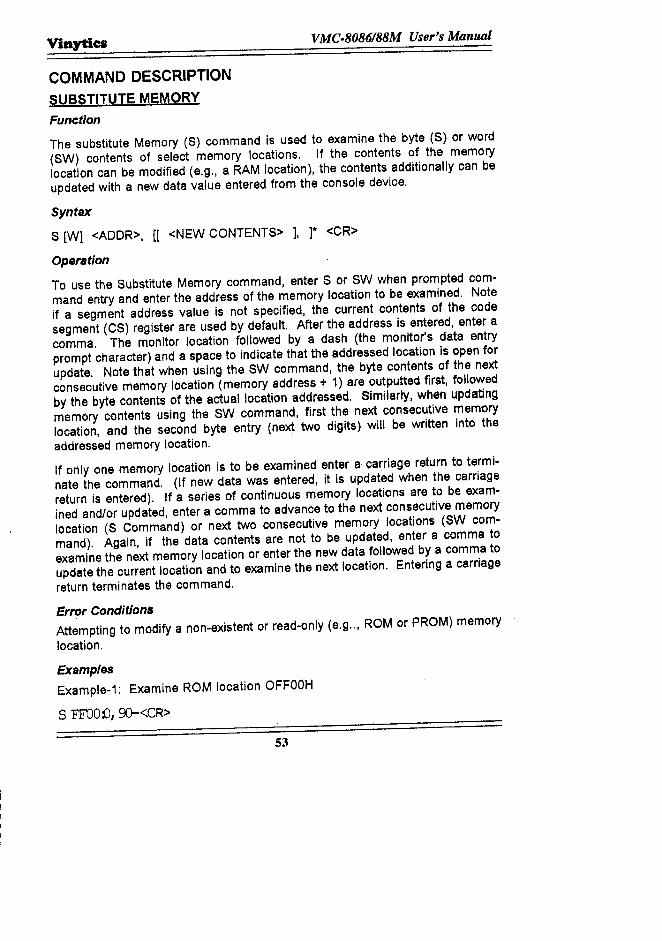
ExamplesExample-1: Examine ROM location OFFOOH
S FFOOD, 9)-<CR>
53
VMC.8086188M User's Manual Vinytics
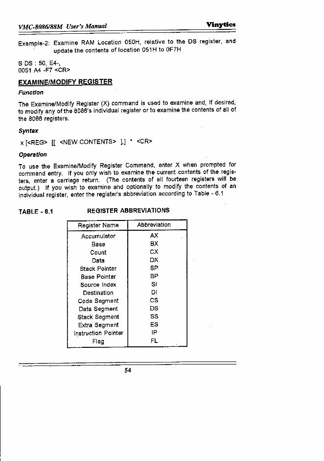
Example-2: Examine RAM Location 050H, relative to the OS register, andupdate the contents of location 051 H to OF7H
S OS : 50, E4-,0051 A4 -F7 <CR>
EXAMINE/MODIFY REGISTER
Function
The Examine/Modify Register (X) command is used to examine and, if desired,to modify any of the 8086's individual register or to examine the contents of all ofthe 8086 registers.
Syntax
x [<REG> [[ <NEW CONTENTS> ],] .• <CR>
Operation
To use the Examine/Modify Register Command, enter X when prompted forcommand entry. If you only wish to examine the current contents of the regis-ters, enter a carriage return. (The contents of all fourteen registers will beoutput.) If you wish to examine and optionally to modify the contents of anindividual register, enter the register's abbreviation according to Table - 6.1
TABLE - 6.1 REGISTER ABBREVIATIONS
Register Name Abbreviation
Accumulator AX
Base BX
Count CX
Data OX
Stack Pointer 5PBase Pointer BPSource Index SIDestination 01
Code Segment CSData Segment OSStack Segment 5SExtra Segment ES
Instruction Pointer IP
Flag FL
54
Vinytics VMC·8086188M User's Manual
When a register abbreviation is entered, the monitor outputs an equal sign("="), the current register contents, the data prompt character ("-") and a space.If you wish to change the register's contents, enter the new contents followed bya comma (to advance to the next" sequential" register) or a carriage return (toterminate the command). The register sequence is in the order shown in Table5.1. Note that the sequence is not circular and that if a comma is entered afterthe contents of the flag (FL) register are examined or a modified, the monitorreturns to the command mode. When a carriage return is entered, the register isupdated (if new contents were entered) and the monitor returns to the commandmode.
Examples
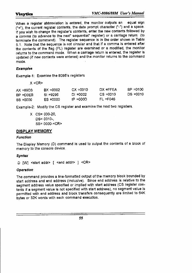
Example-1: Examine the 8086's registers
X <CR>
AX =8903BP =D3EBSS =0000
ex =0002SI =9295ES =0000
CX =001001 =0002IP =0000
ox =FFEACS =0010FL =F046
SP =0100OS =0010
Example-2: Modify the CS register and examine the next two registers.
x CS= 000-20,OS= 0010-,SS= OOOO-<CR>
DISPLAY MEMORYFunction
The Display Memory (D) command is used to output the contents of a block ofmemory to the console device.
Syntax
o [Wj <start addr> [ <end addr> j <CR>
Operation
The command provides a line-formatted output of the memory block bounded bystart address and end address (inclusive). Since end address is relative to thesegment address value specified or implied with start address (CS register con-tents if a segment value is not specified With start address), no segment value ispermitted with end address and block transfers consequently are limited to 64Kbytes or 32K words with each command execution.
55
VMC.8086188M User's Manual Vinytia
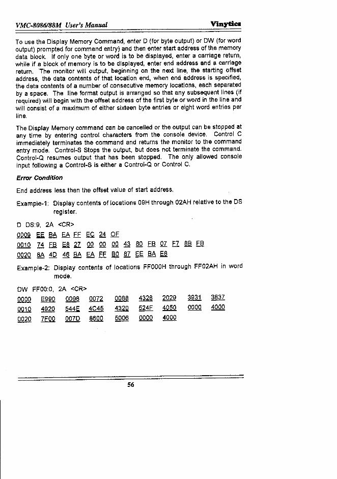
To use the Display Memory Command, enter 0 (for byte output) or OW (for wordoutput) prompted for command entry) and then enter start address of the memorydata block. If only one byte or word is to be displayed, enter a carriage return,while if a block of memory is to be displayed, enter end address and a carriagereturn. The monitor will output, beginning on the next line, the starting offsetaddress, the data contents of that location end, when end address is specified,the data contents of a number of consecutive memory locations, each separatedby a space. The line format output is arranged so that any subsequent lines (ifrequired) will begin with the offset address of the first byte or word in the line andwill consist of a maximum of either sixteen byte entries or eight word entries perline.
The Display Memory command can be cancelled or the output can be stopped atany time by entering control characters from the console device. Control Cimmediately terminates the command and returns the monitor to the commandentry mode. Control-S Stops the output, but does not terminate the command.Control-Q resumes output that has been stopped. The only allowed consoleinput following a Control-S is either a Control·Q or Control C.
Error Condition
End address less than the offset value of start address.
Example-1: Display contents of locations 09H through 02AH relative to the OSregister.
o OS:9, 2A <CR>0009 EE BA EA FF EC 24 OF0010 74 FB E8 27 00 00 00 43 80 FB 07 F7 §l;! FB
0020 8A 40 46 BA EA EE Bo 87 EE SA ~
Example.2: Display contents of locations FFOOOHthrough FF02AH in wordmode.
OW FFOO:O, 2A <CR>
oQOo E990 0098 0072 0088 4328 2029 3931 3837
0010 4920 544E 4C45 4320 524F 4050 0000 4000
0020 ZE.QQ 0070 8600 5006 0000 4000
56
Vinytics VMC.8086188M User's Manual
MOVEFunction
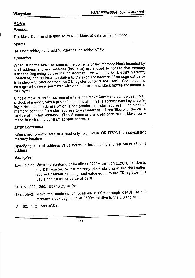
The Move Command is used to move a block of data within memory.
Syntax
M <start addr>, <end addr>, <destination addr> <CR>
Operation
When using the Move command, the contents of the memory block bounded bystart address and end address (inclusive) are moved to consecutive memorylocations beginning at destination address. As with the D (Display Memory)command, end address is relative to the segment address (if no segment valueis implied with start address the CS register contents are used). Consequently,no segment value is permitted with end address, and block moves are limited to64K bytes.
Since a move is performed one at a time, the Move Command can be used to filla block of memory with a pre-defined constant. This is accomplished by specify-ing a destination address which is one greater than start address. The block ofmemory locations from start address to end address + 1 are filled with the valuecontained in start address. (The S command is used prior to the Move com-mand to define the constant at start address).
Error Conditions
Attempting to move data to a read-only (e.g., ROM OR PROM) or non-existentmemory location.
Specifying an end address value which is less than the offset value of startaddress.
Examples
Example-1: Move the contents of locations 0200H through 0250H, relative tothe DS register, to the memory block starting at the destinationaddress defined by a segment value equal to the ES register pius010H and an offset value of 02CH.
M DS: 200, 250, ES+10:2C <CR>
Example-2: Move the contents of locations 0100H through 014CH to thememory block beginning at 0500H relative to the CS register.
M 100, 14C, 500 <CR>
57

VMC-8086188M User's Manual Vinytics
PORT INPUTFunction
The Port Input (I) Command is used to display a byte or word at an input port.
Syntax
I[Wj port addr , [.j. <CR>
58
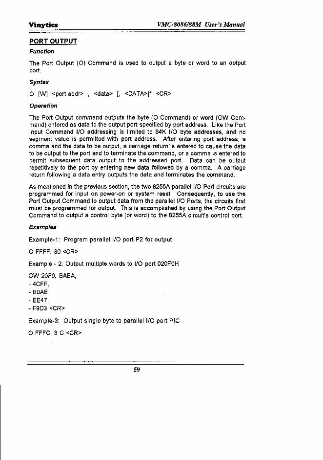
Vinytics VMC·8086188M User's Manual
PORT OUTPUT
Function
The Port Output (0) Command is used to output a byte or word to an outputport.
Syntax
o [W] <port addr> , <data> [, <DATA>]· <CR>
Operation
The Port Output command outputs the byte (0 Command) or word (OW Com-mand) entered as data to the output port specified by port address. Like the PortInput Command I/O addressing is limited to 64K I/O byte addresses, and nosegment value is permitted with port address. After entering port address, acomma and the data to be output, a carriage return is entered to cause the datato be output to the port and to terminate the command, or a comma is entered topermit subsequent data output to the addressed port. Data can be outputrepetitively to the port by entering new data followed by a comma. A carriagereturn following a data entry outputs the data and terminates the command.
As mentioned in the previous section, the two 8255A parallel I/O Port circuits areprogrammed for input on power-on or system reset. Consequently, to use thePort Output Command to output data from the parallel I/O Ports, the circuits firstmust be programmed for output. This is accomplished by using the Port OutputCommand to output a control byte (or word) to the 8255A circuit's control port.
Examples
Example-1: Program parallel I/O port P2 for output
o FFFF, 80 <CR>
Example - 2: Output multiple words to I/O port 020FOH
OW 20FO, BAEA,- 4CFF,- BOAE- EE47,- F9D3 <CR>
Example-3: Output single byte to parallel I/O port PIC
o FFFC, 3 C <CR>
59
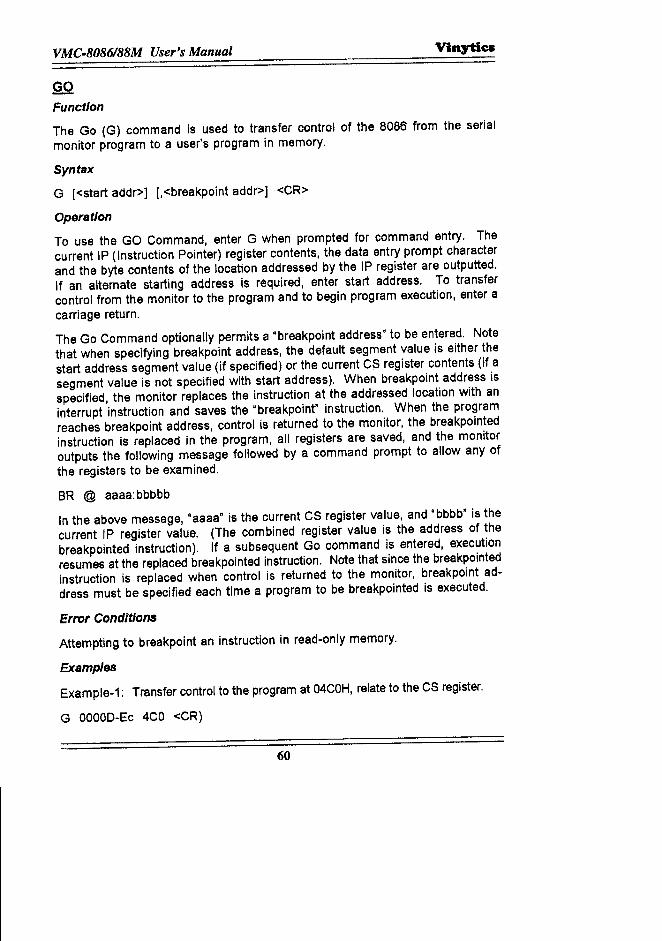
VMC-8086/88M User's Manual Vinytics
GOFunction
The Go (G) command is used to transfer control of the 8086 from the serialmonitor program to a user's program in memory.
Syntax
G [<start addr>] [,<breakpoint addr>] <CR>
Operation
To use the GO Command, enter G when prompted for command entry. Thecurrent IP (Instruction Pointer) register contents, the data entry prompt characterand the byte contents of the location addressed by the IP register are outputted.If an alternate starting address is required, enter start address. To transfercontrol from the monitor to the program and to begin program execution, enter acarriage return.
The Go Command optionally permits a "breakpoint address" to be entered. Notethat when specifying breakpoint address, the default segment value is either thestart address segment value (if specified) or the current CS register contents (if asegment value is not specified with start address). When breakpoint address isspecified, the monitor replaces the instruction at the addressed location with aninterrupt instruction and saves the "breakpoint" instruction. When the programreaches breakpoint address, control is returned to the monitor, the breakpointedinstruction is replaced in the program, all registers are saved, and the monitoroutputs the following message followed by a command prompt to allow any ofthe registers to be examined.
BR @ aaaa:bbbbb
In the above message, "aaaa" is the current CS register value, and "bbbb" is thecurrent IP register value. (The combined register value is the address of thebreakpointed instruction). If a subsequent Go command is entered, executionresumes at the replaced breakpointed instruction. Note that since the breakpointedinstruction is replaced when control is returned to the monitor, breakpoint ad-dress must be specified each time a program to be breakpointed is executed.
Error Conditions
Attempting to breakpoint an instruction in read-only memory.
Examples
Example-1: Transfer control to the program at 04COH,relate to the CS register.
G OOOOD-Ec4CO <CR)
60
Vinytics VMC.8086188M User's Manual
Example-2: Transfer control to the program at 10:0H and break at the instruc-tion in location 10:37H cr
G 010E-24 10:0, 37 <CR>BR @ 0010 : 0037
SINGLE STEPFunctionThe Single Step (N) command is used to execute a single user-program instruc-tion. With each instruction executed, control is returned to the monitor to allowevaluation of the instruction executed.
Syntax
N <start addr>], [[ <start addr>], ]* <CR>
Operation
To use the Single Step command, enter N when prompted for command entry.The monitor will output the current instruction pointer (IP) register contents (thecurrent instruction pointer (IP) register contents (the offset address of the nextinstruction to be executed) and the instruction byte pointed to by the IP (and CS)register. If execution of an instruction at another address is desired, enter startaddress. If start address includes a segment value, both the CS and IP registersare modified. When the comma is entered, the instruction addressed its ex-ecuted and control is returned to the monitor. The monitor saves all of theregister contents and outputs the address (IP register contents) and instructionbyte contents of the next instruction to be executed on the following line. Eachtime a comma is entered, the addressed instruction is executed and the addressand instruction byte contents of the next instruction to be executed are output ona new line.While using the Single Step command to step through a program, a new startaddress can be entered without repeating the command entry. When the commais entered, the instruction addressed is executed and the next instruction's a~dress and byte contents are output. A carriage return terminates the command.
Restrictions1. If an interrupt occurs prior to the completion of a single-stepped instructi~
generates an.interrupt, when the monitor is re-entered, the OS and IP regf&-ters will contain the address of the Interrupt service routine. Consequently,a type 3 (breakpolnt) interrupt instruction (OCCH or OCDH) should not besingle-stepped since its execution would step into the monitor.
61
VMC.8086188M User's Manual Vinytics
2. An instruction that is part of a sequence of instructions that switches be-tween stack segments (l.e., changes the SS and SP register contents) can-not be single-stepped.
ExamplesExample-1: Single Step a series of instructions beginning at 01OOH,relative to
the CS register.
N 0000- 00 100,0102 - 8E,0104 - BA0107 - BO,0109 - EE,010A - BA <CR>
READ HEX FILEFunction
The Read Hex File (R) command allows the monitor to read an 8086 or 8080hexadecimal object file from a paper tape and to load the data read from the fileinto memory.
Syntax
R [ <bias number> 1 <CR>
Operation
To use the Read Hex File Command, enter R when prompted for commandentry. When the tape is loaded in the reader and ready; enter a carriage return,The data read from the file will be written into memory beginning at each record'sload address. If the file is in the 8086 format and includes an execution startaddress record, the CS and IP registers will be up dated with the executionaddress specified in that record. If the file is in 8080 format and includes anEOF (end - of - file) record, the IP register is updated with the execution addressspecified in the EOF record. Note that a segment address value is not used withthe 8080 file format; the data ready is written into memory locations relative to asegment value of zero and, when an EOF record execution address is specified,the CS register is not changed.
When an optional bias number is specified, it is added to each record's loadaddress to offset the file in memory.
62
Vinytics VMC·8086188M User's Manual
Error Conditions
Tape check sum error.
Attempting to load data into non-existent or read-only memory.
Examples
Example-1: Read a file and load the data into memory 256 (decimal) bytesabove the load addresses specified in the file.
R 100 <CR>
WRITE HEX FILEFunction
The Write Hex File (W) command allows a block of memory to be written(output), in either 8086 or 8080 hexadecimal object file format, to a paper tapepunch.
Syntax
W [Xl <start addr> , <end addr> [. <exec addr> 1 <CR>
Operation
To use the Write Hex file command, enter W for 8086 file format or WX for 8080file format and enter start address and end address of the memory block to beoutput. Note that no segment address value is permitted with end address (thestart address value is specified with start address, the current CS register valueis used. When the carriage return is entered, the following information is punchedon the paper tape:
-¢> Six inches of leader (60 null characters)-¢> An extended address record (8086 format only)-¢> The data contents of the memory block bounded by start address and
end address (inclusive).-¢> An end-of-file (EOF) record.-¢> Six inches of trailer (60 null characters).
Optionally, an execution address can be specified prior to entering the carriagereturn. This is the memory address that is loaded into the CS and IP registers(IP register only with 8080 format) when the tape is read with the R command.Depending on the format selected, when execution start address record contain-ing execution address is punched immediately following the tape leader (8086format) or the offset address value of execution address is punched in the EOFrecord (8080 format).
63
VMC·8086188M User's Manual Vinyties
When using the 8086 format (W command), the start address segment value(CS register value if a segment value is not specified) is entered (punched) in theextended address record, and the start address offset value is entered in theload address field of the first data record. The segment and offset addressvalues of execution address are entered in the execution start address record(CS register contents if a segment address value is not specified with executionaddress).
When using the 8080 format (WX command), the start address offset value ispunched in the load address offset value is punched in the load address field ofthe first data record. Execution address, if specified, is punched in the EOFrecord. Note that a segment address value is not permitted with executionaddress or end address and that the start address segment value is used only todefine the starting address of the memory block and that it is not punched on thetape. The Write Hex File command can be cancelled or stopped at any time byentering control characters from the console device. Control C cancels thecommand and prompts for new command entry. Control S stops the output, butdoes not cancel the command. Control-Q resumes output that has been stopped.The only console input allowed following a Control-S is either Control-Q orControl-C.
Error ConditionsSpecifying a value for end address that is less than offset value of start address.
ExamplesExample-1: Output the memory block bounded by 04H and 06DDH, relative to
the current CS register, to an 8086 file with an execution addressof CS 040H.
W 4, 6DD, 40 <Cr>
UPLOADINGXTALK provides a feature by which the data stored in VMC-8603 can be storedin the floppy diskette of PCIXT/AT. This can be achieved.by following the instruc-tions given as below:
a) Write W 0: 200, 288b) Press Home Key of the Computer Keyboard, COMMAND? will be displayed
in the 25th line.c) Write CA ONd) Press <CR> thrice and data from AD1 to AD2 will be displayed
e) Again press Home key.f) Write CA OFF and press <CR>
64
Vinytics VMC.8086188M User's Manual
g) The computer will show you on the screen as follows:"Information is still in the capture.Do you want to save it (Y/N)".
If you want to save the data, press Y. After pressing 'Y' It will ask you:"Write capture buffer to what file? "
Name the file In which you want to save the data following .OAT e.g.,ABC.OAT and press <CR>.
i) After pressing <CR> on the screen, you will get"File successfully written, Press <Enter>".
j) Data captured will be stored in the file as defined by the file name.
DOWNLOADING THE ABOVE FILE FROM PC/XT/AT TO 8085 KITThe following procedure is to be adopted for downloading the above file fromPC/XT/AT to VMC-8603.
The 'R' command loads the data from your diskette/PC to the memory of the KIt.
a) Press 'R' key.b) Press 'Home key' of the PC Keyboard, COMMAND? will appear on the 25th
line.c) Name the file in which you want to send data from floppy diskette to memory.
Write SEND ABC.DAT in command prompt and press <CR> key twice.d) The programs stored in the file will be loaded into memory of your kit at the
address specified in the program.
ABORTING THE OPERATIONFor aborting the XTALK, write "QUIT" at COMMAND? prompt.
a) A"" prompt is displayed on the screen.b) Press Home key on the computer keyboard. "COMMAND?" will be displayed
on the 25th line.c) Write 'QU' and XTALK operation is aborted.
65

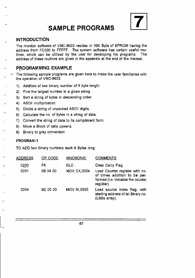
SAMPLE PROGRAMS
INTRODUCTIONThe monitor software of VMC-8603 resides in 16K Byte of EPROM having theaddress from FCOOOto FFFFF. The system software has certain useful rou-tines, which can be utilised by the user for developing his programs: Theaddress of these routines are given in the appendix at the end of the manual.
PROGRAMMING EXAMPLE,j/ The following sample programs are given here to make the user familiarise with
the operation of VMC-8603.
1) Addition of two binary number of 8 byte length.2) Find the largest number in a given string.3) Sort a string of bytes in descending order.4) ASCII multiplication.5) Divide a string of unpacked ASCII digits.6) Calculate the no. of bytes in a string of data.7) Convert the string of data to its compliment form.8) Move a Block of data upward.9) Binary to gray conversion.
PROGRAM-1
TO ADD two Binary numbers each 8 Bytes long:
ADDRESS OP CODE MNEMONIC COMMENTS
0209 F8 CLC' Clear Carry Flag.0201 B9 04 00 MOV,CX,0004 Load Counter register with no.
of times addition to be per-formed (i.e. Initialize the counterregister).
0204 BE 00 03 MOV SI,0300 Load source Index Reg. withstarting address of 1stBinary no.(LSBs array).
67
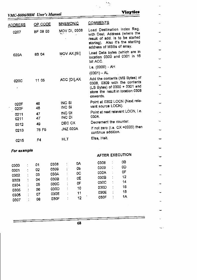
\..1"'>..,
VMC-8086188M User's Manual ViOytiCil
ADDRESS OP CODE MNEMONIC COMMENTS
0207 8F 08 03 ~OV 01, 03~8 Load Destination Index Reg.with Dest. Address (where theresult of add. is to be startedstoring). Also it's the startingaddress of MSBs of array.
020A 8B 04 ~OV AX,[SI] Load Data bytes (which are inlocation 0300 and 0301 in 16bit ACC.
l.e, (0300) - AH
(0301) - AL
020C 11 05 ADC [Dll,AX Add the contents (MS Bytes) of0308, 0309 with the contents(LS Bytes) of 0300 + 0301 andstore the result in location 0308onwards.
020F 46 INCSI Point at 0302 LOCN (Next reia-
020F 46 INC SI vant source LOCN).
0211 47 INC 01 Point at next relevant LOCN, Le.
0211 47 INC 01 0304.
0212 49 DEC CX Decrement the counter.
0213 75 F5 JNZ 020A If not zero (l.e, CX =0000) thencontinue addition.
0215 F4 HLT Else, Halt.
ForexsmpleAFTER EXECUTION
0300 01 0308 OA 0308 OB
0301 02 0309 Ob 0309 00
0302 03 030A OC 030A OF
0303 04 0308 OE 0308 12
0304 05 030C OF 030C 14
0305 06 0300 10 0300 16
0306 07 030E 11 030E 18
0307 08 030F 12 030F 1A
68
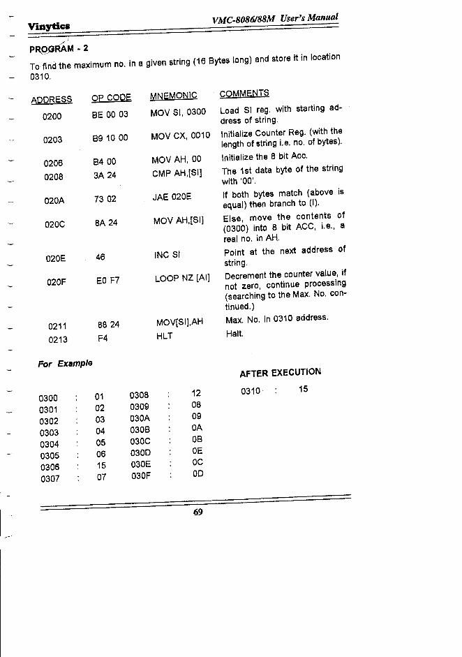
Vinytlc:sVMC.8086188M User's Manual
:
PR,QGRAM.2To find the maximum no. in a given string (16 Bytes long) and store it in location
0310.
ADDRESS Op CODE MNEMONIC COMMENTS
0200 BE 00 03 MOV 51,0300 Load 51 reg. with starting ad-dress of string.
0203 B9 10 00 MOV CX, 0010 Initialize Counter Reg. (with thelength of string l.e. no. of bytes).
0206 B400 MoV AH, 00 Initialize the 8 bit Ace.
0208 3A 24 CMP AH,[51] The 1st data byte of the stringwith '00'.
020A 7302 JAE 020E If both bytes match (above isequal) then branch to (I).
020C 8A 24 MOV AH,[51] Else, move the contents of(0300) into 8 bit ACC, i.e., areal no. in AH.
020E . 46 INC 51 Point at the next address ofstring.
020F EO F7 LOOP NZ [AI] Decrement the counter value, ifnot zero, continue processing(searching to the Max. No. con-tinued.)
0211 8824 MOV[51],AH Max. No. in 0310 address.
0213 F4 HLT Halt.
For ExampleAFTER EXECUTION
0300 01 0308 12 0310 15
0301 02 0309 08
0302 03 030A 09
0303 04 030B OA
0304 05 030C OB
0305 06 0300 OE
0306 15 030E OC
0307 07 030F 00
69
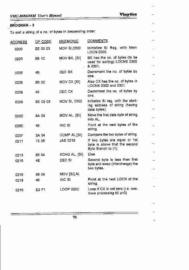
VMC.8086188M User's Manual Vinytics
~OGRAM -3
To sort a string of a no. of bytes in descending order:
ADDRESS OP CODE MNEMONIC COMMENTS
0200 BE 00 03 MOV SI,0300 Initialize SI Reg. with MemLOCN 0300.
0203 8B 1C MOV BX, [SI] BX has the no. of bytes (to beused for sorting) LOCNS 0300& 0301.
0205 4B DEC BX Decrement the no. of bytes byone.
0206 8B OC MOV CX [SI] Also CX has the no. of bytes inLOCNS 0300 and 0301.
0208 49 DEC CX Decrement the no. of bytes byone.
0209 BE 02 03 MOV SI, 0302 Initialize SI reg. with the start-ing address of string (havingdata bytes).
020C 8A 04 MOV AL, [SI] Move the first data byte of stringinto AL.
020E 46 INC SI Point at the next bytes of thestring.
020F 3A 04 COMP AL,[Slj Compare the two bytes of string.
0211 7306 JAE 0219 If two bytes are equal or 1stbyte is above that the secondByte Branch to (1).
0213 86 04 XCHG AL, [SI] Else
0215 4E DEC SI Second byte is less than firstbyte and swap (interchange) thetwo bytes.
0216 8804 MOV [SI],AL
0218 46 INC SI Point at the next LOCN of thestring.
0219 E2 F1 LOOP 020C Loop if CX is not zero (i.e. con-tinue processing till z=O)
70
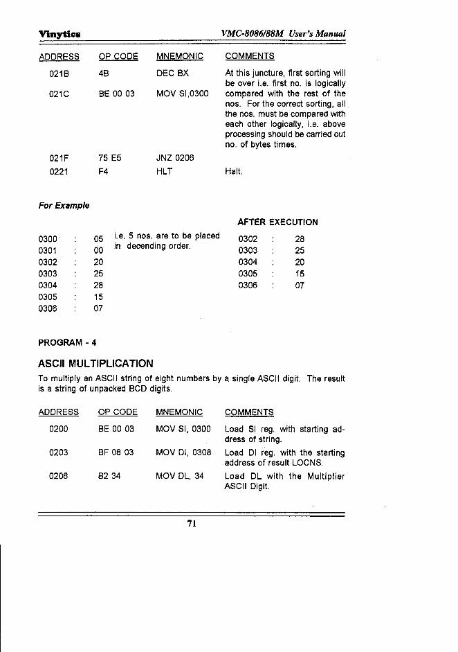
Vinytics VMC·8086188M User's Manual
ADDRESS OP CODE MNEMONIC COMMENTS
021B 4B DEC BX At this juncture, first sorting willbe over Le. first no. is logically
021C BE 0003 MOV 51,0300 compared with the rest of thenos. For the correct sorting, allthe nos. must be compared witheach other logically, Le. aboveprocessing should be carried outno. of bytes times.
021F 75 E5 JNZ 0206
0221 F4 HLT Halt.
For Example
AFTER EXECUTION
0300 05 i.e. 5 nos. are to be placed 0302 280301 00 in decending order. 0303 250302 20 0304 200303 25 0305 150304 28 0306 070305 150306 07
PROGRAM·4
ASCII MULTIPLICATIONTo multiply an ASCII string of eight numbers by a single ASCII digit. The resultis a string of unpacked BCD digits.
ADDRESS OP CODE MNEMONIC COMMENTS
0200 BE 00 03 MOV 51,0300 Load 51 reg. with starting ad-dress of string.
0203 BF 08 03 MOV 01,0308 Load 01 reg. with the startingaddress of result LOCNS.
0206 B234 MOV DL, 34 Load DL with the MultiplierASCII Digit.
71
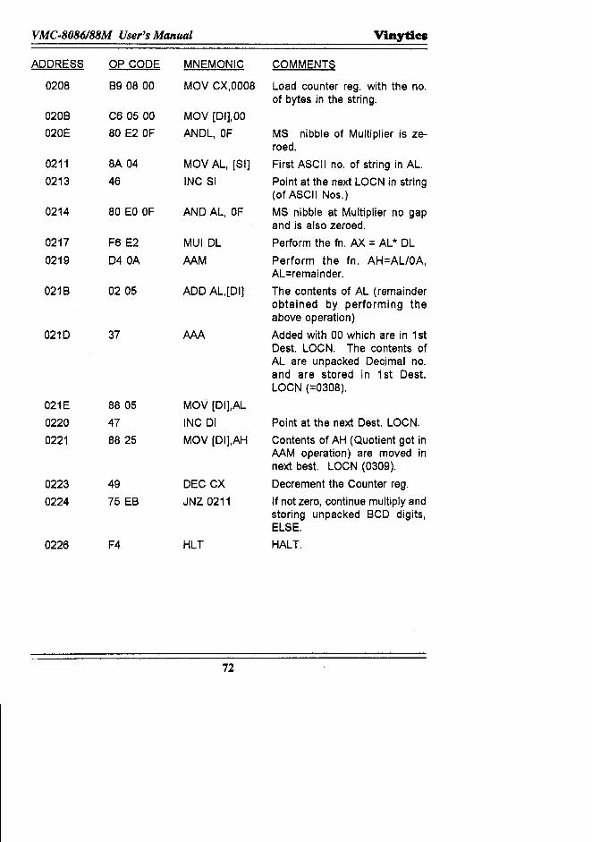
VMC·8086188M User's Manual VinytiCil
ADDRESS OP CODE MNEMONIC COMMENTS
0208 B9 08 00 MOV CX,0008 Load counter reg. with the no.of bytes in the string.
0208 C6 05 00 MOV [01],00020E 80 E2 OF ANDL, OF MS nibble of Multiplier is ze-
roed.0211 8A 04 MOV AL, [SI] First ASCII no. of string in AL.0213 46 INC SI Point at the next LOCN in string
(of ASCII Nos.)0214 80 EO OF AND AL, OF MS nibble at Multiplier no gap
and is also zeroed.0217 F6 E2 MUIDL Perform the fn. AX = AL* DL0219 D40A AAM Perform the fn. AH=ALlOA,
AL=remainder.021B 0205 ADD AL,[DI] The contents of AL (remainder
obtained by performing theabove operation)
0210 37 AAA Added with 00 which are in 1stDest. LOCN. The contents ofAL are unpacked Decimal no.and are stored in 1st Dest.LOCN (=0308).
021E 8805 MOV [DI],AL0220 47 INC 01 Point at the next Dest. LOCN.
0221 8825 MOV [DI],AH Contents of AH (Quotient got inAAM operation) are moved innext best. LOCN (0309).
0223 49 DEC CX Decrement the Counter reg.
0224 75 EB JNZ 0211 If not zero, continue multiply andstoring unpacked BCD digits,ELSE.
0226 F4 HLT HALT.
72
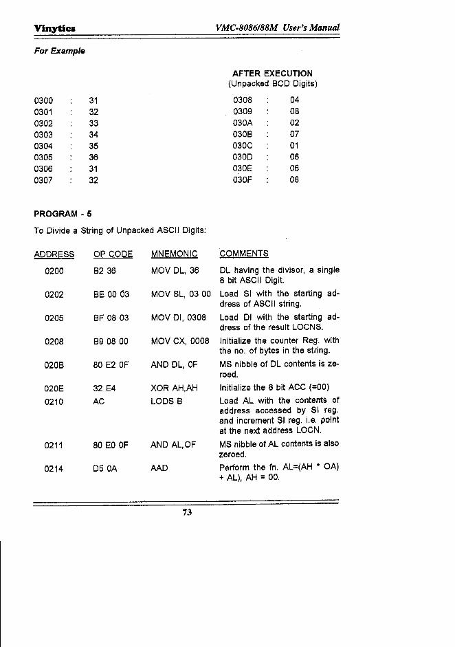
Vinytics VMC·8086188M User's Manual
For Example
AFTER EXECUTION(Unpacked BCD Digits)
0300 31 0308 040301 32 0309 08
0302 33 030A 02
0303 34 030B 07
0304 35 030C 010305 36 030D 060306 31 030E 060307 32 030F 08
PROGRAM - 5
To Divide a String of Unpacked ASCII Digits:
ADDRESS OP CODE MNEMONIC COMMENTS
0200 8236 MOV DL, 36 DL having the divisor, a single8 bit ASCII Digit.
0202 8E 00 03 MOV SL, 0300 Load SI with the starting ad-dress of ASCII string.
0205 8F 0803 MOV DI, 0308 Load DI with the starting ad-dress of the result LOCNS.
0208 B9 08 00 MOV CX, 0008 Initialize the counter Reg. withthe no. of bytes in the string.
0208 80 E2 OF AND DL, OF MS nibble of DL contents is ze-roed.
020E 32 E4 XOR AH,AH Initialize the 8 bit ACC (=00)
0210 AC LODS B Load AL with the contents ofaddress accessed by SI reg.and increment SI reg. i.e, pointat the next address LOCN.
0211 80 EO OF AND AL,OF MS nibble of AL contents is alsozeroed.
0214 D50A MD Perform the fn. AL=(AH * OA)+ AL), AH = 00.
73
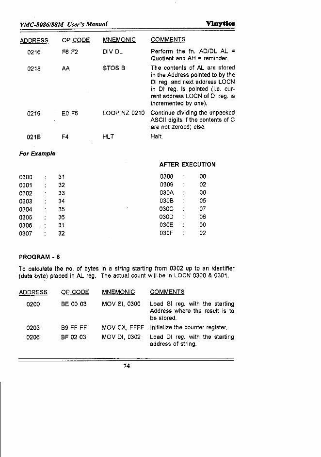
VMC-8086/88M User's Manual V'anytics
ADDRESS
0216
OP CODE
F6 F2
0218 AA
MNEMONIC
DIV DL
COMMENTS
Perform the fn. AD/DL AL =Quotient and AH = reminder.The contents of AL are storedin the Address pointed to by the01 reg. and next address LOCNin 01 reg. is pointed (Le. cur-rent address LOCN of 01 reg. isincremented by one).Continue dividing the unpackedASCII digits if the contents of Care not zeroed; else.Halt.
STOS B
0219 EO F5 LOOP NZ 0210
021B F4 HLT
For Example
0300 310301 320302 330303 340304 350305 360306 310307 32
PROGRAM - 6
AFTER EXECUTION
0308 000309 02030A 00030B 05030C 070300 06030E 00030F 02
To calculate the no. of bytes in a string starting from 0302 up to an identifier(data cyte) placed in AL reg. The actual count will be in LOCN 0300 & 0301.
ADDRESS OP CODE MNEMONIC COMMENTS
0200 BE 00 03 MOV SI, 0300 Load SI reg. with the startingAddress where the result is tobe stored.
0203 B9 FF FF MOV CX, FFFF Initialize the counter register.
0206 BF 0203 MOV 01,0302 Load 01 reg. with the startingaddress of string.
74
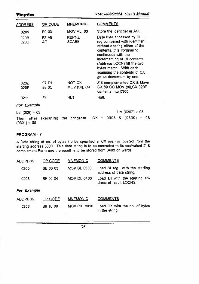
Vinytics VMC·8086188M User's Manual
COMMENTSADDRESS
02090208020C
OP CODE
BO 03F2 AEAE
MNEMONIC
MOV AL, 03REPNZSCASB
0200020F
F7D1890C
NOT CXMOV [SI], CX
0211 F4 HLT
For Example
Let (309) = 03Then after executing the program(0301) = 00
PROGRAM -7
Store the identifier in ASL.Data byte accessed by 01reg.compared with identifier'without altering either of thecontents, this comparingcontinuous with theincrementing of 01 contents(Address LOCN) till the twobytes match. With eachscanning the contents of CXgo on decrement by one.Z'S complemented CX & MoveCX 89 OC MOV (si),CX 020Fcontents into 0300.Halt.
Let (0302) = 03CX = 0008 & (0300) = 08
A Data string of no. of bytes (to be specified in CX reg.) is located from thestarting address 0300. This data string is to be converted to its equivalent 2' Scomplement Form and the result is to be stored from 0400 on wards.
ADDRESS OP CODE MNEMONIC COMMENTS
0200 BE 00 03 MOV SI, 0300 Load SI reg., with the startingaddress of data string.
0203 8F 0004 MOV 01,0400 Load 01 with the starting ad-dress of result LOCNS.
For Example
ADDRESS OP CODE MNEMONIC COMMENTS
0206 89 10 00 MOV CX, 0010 Load CX with the no. of bytesin the string.
75
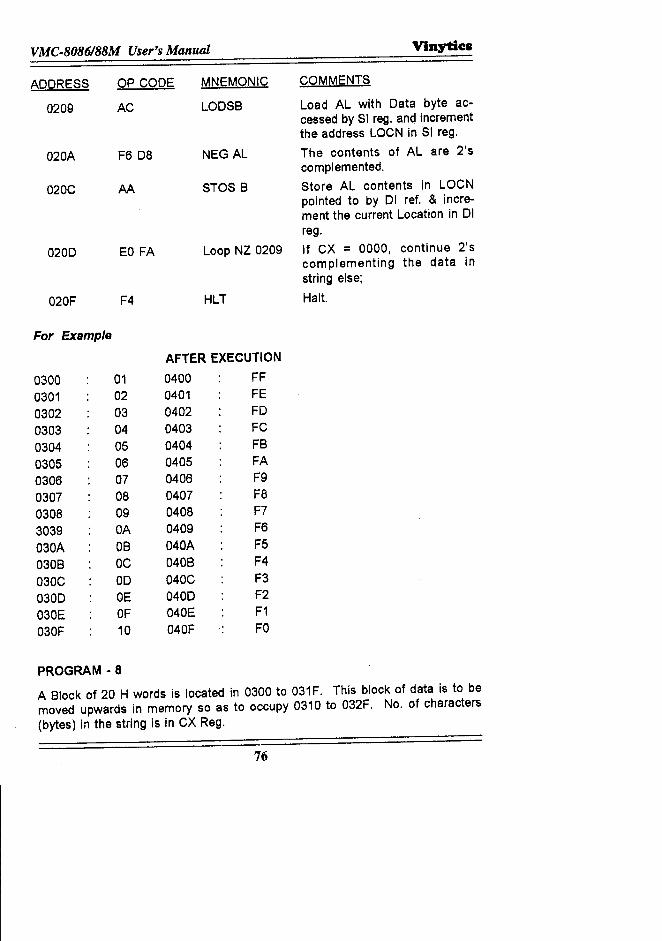
VMC-8086188M User's Manual Vinytics
ADDRESS OP CODE MNEMONIC COMMENTS
0209 AC LOOSB Load AL with Data byte ac-cessed by SI reg. and incrementthe address LOCN in SI reg.
o2oA F608 NEG AL The contents of AL are 2'scomplemented.
O2OC AA STOS B Store AL contents in LOCNpointed to by 01 ref. & incre-ment the current Location in 01reg.
0200 EO FA Loop NZ 0209 If CX = 0000, continue 2'5complementing the data instring else;
o20F F4 HLT Halt.
For Example
AFTER EXECUTION
0300 01 0400 FF
0301 02 0401 FE0302 03 0402 FO0303 04 0403 FC
0304 05 0404 FB
0305 06 0405 FA0306 07 0406 F90307 08 0407 F8
0308 09 0408 F7
3039 OA 0409 F6
030A OB 040A F5
030B OC 040B F4
030C 00 040C F3
0300 DE 0400 F2
030E OF 040E F1
030F 10 040F FO
PROGRAM - 8
A Block of 20 H words is located in 0300 to 031F. This block of data is to bemoved upwards in memory so as to occupy 0310 to 032F. No. of characters
(bytes) in the string is in CX Reg.
76
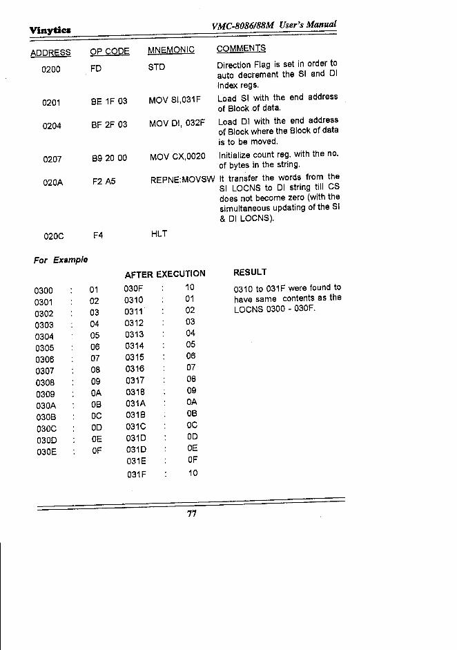
Vinytics VMC.8086188M User's Manual
ADDRESS OP CODE MNEMONIC COMMENTS
0200 FD STD Direction Flag is set in order toauto decrement the Sl and 01index regs.
0201 BE 1F 03 MoV SI,031F Load $1 with the end addressof Block of data.
0204 BF 2F 03 MOV DI, 032F Load 01 with the end addressof Block where the Block of datais to be moved.
0207 B9 2000 MOV CX,0020 Initialize count reg. with the no.of bytes in the string,
020A F2 A5 REPNE:MOVSW It transfer the words from theSI LOCNS to 01 string till CSdoes not become zero (with thesimultaneous updating of the SI& DI LOCNS).
020C F4 HLT
For Example
AFTER EXECUTION RESULT
0300 01 030F 10 0310 to 031F were found to
0301 02 0310 01 have same contents as the
0302 03 0311 02 LoCNS 0300 - 030F.
0303 04 0312 03
0304 05 0313 04
0305 06 0314 05
0306 07 0315 06
0307 08 0316 07
0308 09 0317 08
0309 OA 0318 09
030A OB 031A OA
030B OC 031B OB
030C 00 031C OC
0300 OE 0310 00
030E OF 0310 OE031E OF
031F 10
77
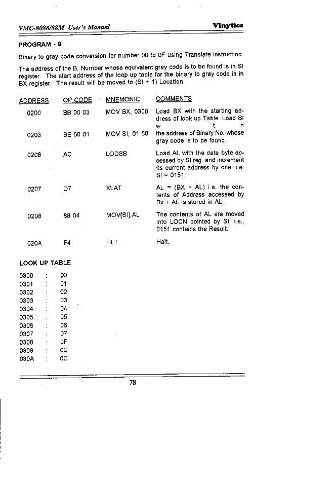
VMC.8086188M User's Manual Vinytics
PROGRAM - 9
Binary to gray code conversion for number 00 to OF using Translate instruction.
The address of the B. Number whose equivalent gray code is to be found is in SIregister. The start address of the loop up table for the binary to gray code is inBX register. The result will be moved to (SI + 1) Location.
ADDRESS
0200
OP CODE
BB 00 03
0203 BE 50 01
0206 AC
0207 07
0208 88 04
020A F4
LOOK UP TABLE
0300 000301 010302 020303 030304 040305 050306 060307 070308 OF0309 OE030A OC
MNEMONIC COMMENTS
MOV BX, 0300 Load BX with the starting ad-dress of look up Table. Load SIwit h
MOV SI, 01 50 the address of Binary No. whosegray code is to be found.
LODSB Load AL with the data byte ac-cessed by SI reg. and incrementits current address by one, I.e.SI = 0151.
XLAT AL = (BX + AL) i.e, the con-tents of Address accessed byBx + AL is stored in AL.
MOV[SI],AL The contents of AL are movedinto LOCN pointed by SI, I.e.,0151 contains the Result.
HLT Halt.
78
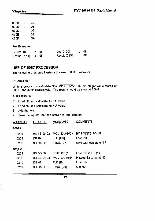
Vinytics VMC-8086/88M User's Manual
030B 00030C 080300 09030E OB030F OA
For Example
Let (0150)Result (0151)
0505
Let (0150)Result (0151
09OE
USE OF 8087 PROCESSORThe following programs illustrate the use of 8087 processor.
PROBLEM: 1
Write a program to calculate N3= ..JN12 + N22 32 bit integer value stored at300 Hand 304H respectively. The result should be store at 308H.
Steps required:
1) Load N1 and calculate its N12 value
2) Load N2 and calculate its N22 value
3) Add the two.
4) Take the square root and store it in 308 location.
ADDRESS OP CODE MNEMONIC COMMENTS
Step-1
0200 9B BB 0003 MOV BX,0300H BX POINTS TO N1
0204 DB 07 FLO [BX] Load N1
0206 9B DA OF FMUL [OX] Give wait calculate N12
Step-20209 9B DO 09 FSTP ST (1) Load N2 in ST (1)
020C 9B BB 0403 MOV BX, 0304 H Load Bx to point N2
0210 DB 07 FLO [Bx] Load N2
0212 9B DA OF FMUL [Bx] Get N22
79
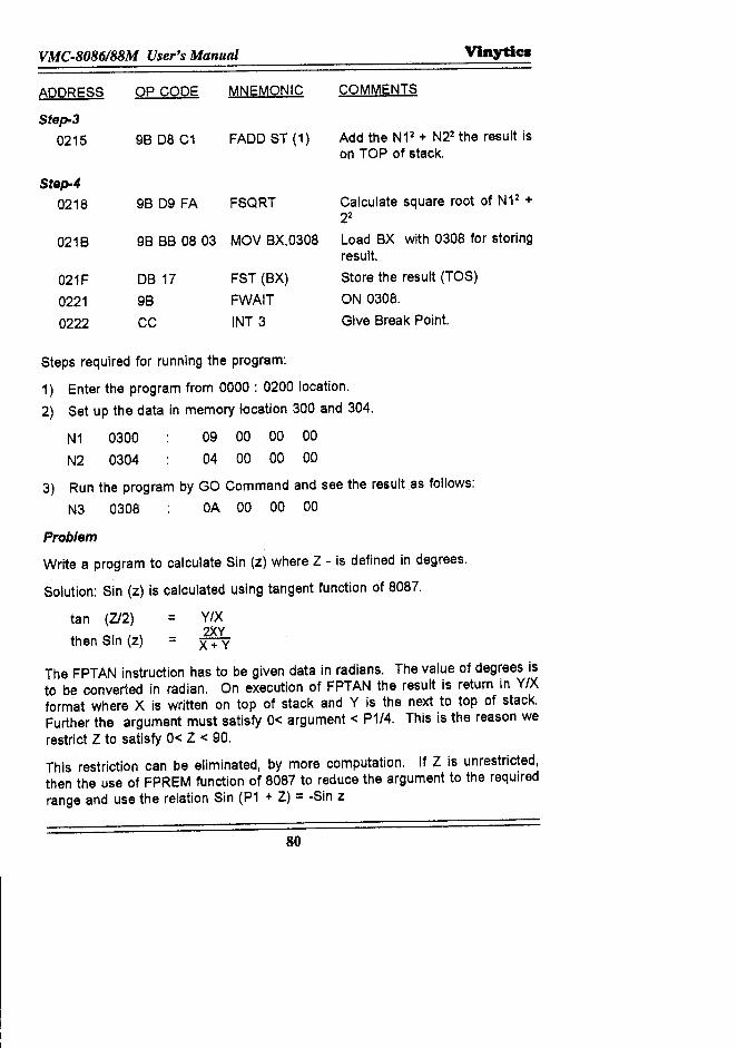
VMC.8086188M User's Manual VlnytiC8
ADDRESS OP CODE MNEMONIC COMMENTS
Step-3
0215 9B 08 C1 FADD ST (1) Add the N12 + N22 the result ison TOP of stack.
Step-4
0218 9B 09 FA FSQRT Calculate square root of N12 +22
021B 9B BB 08 03 MOV BX,0308 Load BX with 0308 for storingresult.
021F DB 17 FST (BX) Store the result (TOS)
0221 9B FWAIT ON 0308.
0222 CC INT 3 Give Break Point.
Steps required for running the program:
1) Enter the program from 0000 : 0200 location.
2) Set up the data in memory location 300 and 304.
N1 0300
N2 0304
09 00 00 00
04 00 00 00
3) Run the program by GO Command and see the result as follows:
N3 0308 OA 00 00 00
Problem
Write a program to calculate Sin (z) where Z - is defined in degrees.
Solution: Sin (z) is calculated using tangent function of 8087.
=Y/X2XYX+Y
tan (Z/2)
then Sin (z)=
The FPTAN instruction has to be given data in radians. The value of degrees isto be converted in radian. On execution of FPTAN the result is return in YIXformat where X is written on top of stack and Y is the next to top of stack.Further the argument must satisfy 0< argument < P1/4. This is the reason werestrict Z to satisfy 0< Z < 90.
This restriction can be eliminated, by more computation. If Z is unrestricted,then the use of FPREM function of 8087 to reduce the argument to the requiredrange and use the relation Sin (P1 + Z) = -sln z
80
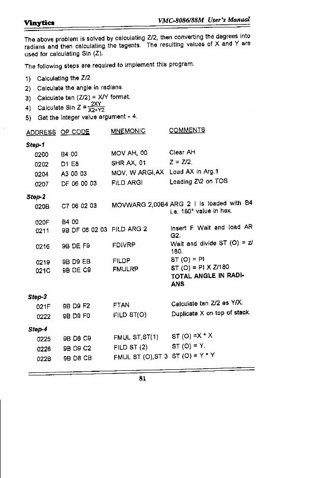
ViJlytics VMC.8086188M User's Manual
The above problem is solved by calculating ZJ2, then converting the degrees intoradians and then calculating the tagents. The resulting values of X and Yareused for calculating Sin (Z).
The following steps are required to implement this program.
1) Calculating the Z/22) Calculate the angle in radians.3) Calculate tan (Z/2) = XIY format.
4) Calculate Sin Z = ~~2
5) Get the integer value argument - 4.
ADDRESS OP CODE MNEMONIC COMMENTS
Step-10200 8400 MOV AH, 00 Clear AH
0202 D1 E8 SHR AX, 01 Z = ZJ2.
0204 A3 00 03 MOV, W ARGI,AX Load AX in Arg.1
0207 DF 06 00 03 FILD ARGI Loading Z\2 on TOS
Step-20208 C7 06 02 03 MOVWARG 2,0084 ARG 2 I is loaded with 84
t.e. 1800 value in hex.
020F 84000211 98 DF 06 02 03 FILD ARG 2 Insert F Wait and load AR
G2.
0216 98 DE F9 FDIVRP Wait and divide ST (0) = zl180.
0219 98 D9 E8 FILDP ST (0) = PI
021C 98 DE C9 FMULRP ST (0) :::PI X Z/180TOTAL ANGLE IN RADI.ANS
Step-3021F 98 D9 F2 FTAN Calculate tan Z/2 as Y/X.
0222 98 D9 FO FILD ST(O) Duplicate X on top of stack.
Step-4
0225 98 D8 C9 FMUL ST,ST(1) ST (0) :eX* X
0228 98 D9 C2 FILD ST (2) ST (0) = Y.
0228 98 D8 C8 FMUL ST (O),ST 3 ST (0) = Y * Y
81
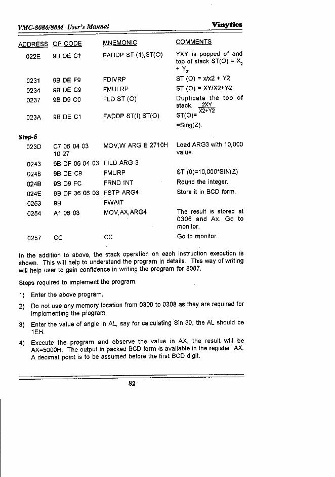
VMC.8086188M User's Manual Vinytics
ADDRESS OP CODE MNEMONIC COMMENTS
022E 98 DE C1 FADDP ST (1),ST(O) YXY is popped of andtop of stack ST(O) = ><:z
. + Y2·
0231 98 DE F9 FDIVRP ST (0) = xJx2 + Y2
0234 98 DE C9 FMULRP ST (0) = XY/X2+Y.2
0237 9809 CO FLO ST (0) Duplicate the top ofstack. 2XY
023A 98 DE C1 FADDP ST(I),ST(O) ST(O)= )(2+Y2
=Sing(Z),
Step-5
0230 C7 06 0403 MOV,W ARG E 2710H Load ARG3 with 10,0001027 value.
0243 98 OF 060403 FILD ARG 3
0248 98 DE C9 FMURP ST (0)=10,OOO*SIN(Z)
0248 9809 FC FRNDINT Round the integer.
024E 98 OF 360603 FSTP ARG4 Store it in 8CD form.
0253 98 FWAIT
0254 A1 0603 MOV,AX,ARG4 The result is stored at0306 and Ax. Go tomonitor.
0257 CC CC Go to monitor.
In the addition to above, the stack operation on each instruction execution isshown. This will help to understand the program in details. This way of writingwill help user to gain confidence in writing the program for 8087.
Steps required to implement the program.
1) Enter the above program.
2) Do not use any memory location from 0300 to 0308 as they are required forimplementing the program.
3) Enter the value of angle in AL, say for calculating Sin 30, the AL should be1EH.
4) Execute the program and observe the value in AX, the result will beAX=5000H. The output in packed 8CD form is available in the register AX.A decimal point is to be assumed before the first 8CD digit.
82
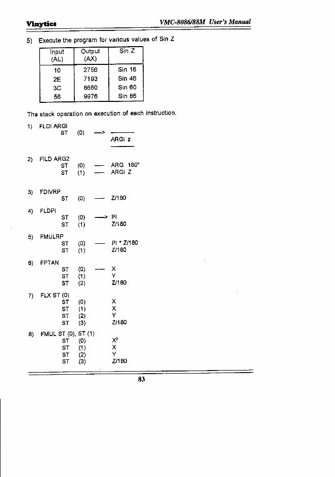
Vinytic:s VMC.8086188M User's Manual
5) Execute the program for various values of Sin Z
Input Output Sin Z(AL) (AX)
10 2756 Sin 162E 7193 Sin 463C 8660 Sin 6056 9976 Sin 86
The stack operation on execution of each instruction.
1) FLDI ARGIST (0) ->
ARGI Z
2) FILD ARG2ST (0) ARG 180·
ST (1 ) ARGI Z
3) FDIVRPST (0) .- Z1180
4) FLOPIST (0) -> PIST (1 ) Z1180
5) FMULRPST (0) PI * Z1180ST (1 ) Z1180
6) FPTANST (0) XST (1 ) YST (2) Z1180
7) FLX ST (0)ST (0) XST (1 ) XST (2) YST (3) Z1180
8) FMUL ST (0), ST (1)ST (0) X2
ST (1 ) XST (2) YST (3) Z1180
83

VMC·8086188M User's Manual
9) FLO ST (2)ST (0) YST (1 ) X2ST (2) XST (3) YST (4) Z1180
10) FLO ST (0), ST (3)ST (0) X2ST (1 ) X2ST (2) XST (3) YST (4) Z1180
11) FADDP ST (1) ST (0)ST (0) X2 + y2ST (1 ) XST (2) yST (3) Z/180
12) FOIVRPST (0) XJX2 + y2ST (1 ) yST (2) Z/180
13) FMULRPST (0) XYfX2 + y2ST (1 ) Z/180
14) FLD ST (0)ST (0) XY/X2 + y2ST (1 ) XY/X2 + y2ST (2) Z/180
15) FADD PST (1), ST (0)ST (0) 2XY1X2 + y2ST (0) =SIN (Z)
1S) FLDI ARG 3ST (0) 10,000ST (1 ) SIN(Z)
17) FMUR PST (0) 10,000 X
SIN Z
18) FRNDINTST (0) Rounding the integer
19) FSTP AR G 4The argument has the result.
84
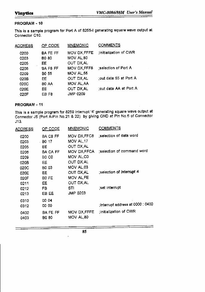
Vinytlcs VMC·8086188M User's Manual
PROGRAM - 10
This is a sample program for Port A of 8255-1 generating square wave output atConnector C10.
ADDRESS OP COPE MNEMONIC COMMENTS
0200 BA FE FF MOV DX,FFFE ;initialization of CWR0203 BO 80 MOV AL,800205 EE OUT DX,AL0206 BA Fa FF MOV DX,FFF8 ;selection of Port A0209 BO 55 MOV AL,55020B EE OUT DX,AL ;out data 55 at Port A020C BOAA MOV AL,AA020E EE OUT DX,AL ;out data AA at Port A020F EB Fa JMP 0209
PROGRAM -11
This is a sample program for 8259 interrupt '4' generating square wave output atConnector J5 (Port A-Pin NO.21 & 22) by giving GND at Pin NO.6 of ConnectorJ13.
ADDRESS OP CODE MNEMONIC COMMENTS
0200 SA C8 FF MOV DX,FFC8 ;selection of data word
0203 BO 17 MOV AL,170205 EE OUT DX,AL0206 BA CA FF MOV DX,FFCA ;selection of command word
0209 SO CO MOV AL,CO020B EE OUT DX,AL020C 8003 MOV AL,03020E EE OUT DX,AL ;selection of Interrupt 4
020F BO FE MOV AL,FE0211 EE OUT DX,AL0212 FB STI ;set interrupt
0213 EB EE JMP 0203
0310 00040312 0000 ;interrupt address at 0000 : 0400
0400 SA FE FF MOV DX,FFFE ;initialization of CWR
0403 BO 80 MOV AL,aO
85
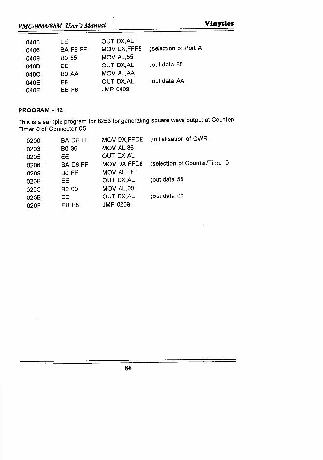
VMC-8086188M User's Manual V'mytic:s
0405040604090408040C040E040F
EE8A F8 FF8055EE80 AAEEEB F8
OUT DX,ALMOV DX,FFF8 ;selection of Port AMOV AL,55OUT DX,AL ;out data 55MOV AL,AAOUT DX,AL ;out data AAJMP 0409
PROGRAM - 12
This is a sample program for 8253 for generating square wave output at Counter/Timer 0 of Connector C5.
0200 BA DE FF MOV DX,FFDE ;initialisation of CWR
0203 8036 MOV AL,360205 EE OUT DX,AL0206 8A 08 FF MaV DX,FFD8 ;selection of CounterlTimer 0
0209 80 FF MaV AL,FF0208 EE OUT DX,AL ;out data 55
020C BO 00 MaV AL,OO020E EE OUT DX,AL ;out data 00
020F E8 F8 JMP 0209
86
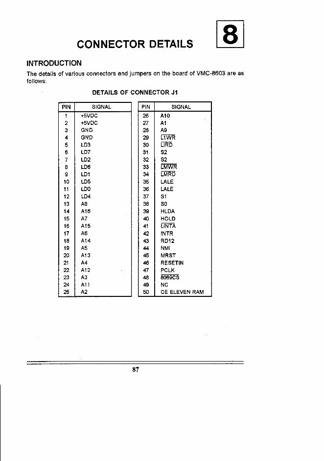
CONNECTOR DETAILS
INTRODUCTIONThe details of various connectors and jumpers on the board of VMC-8603 are asfollows:
DETAILS OF CONNECTOR J1
PIN SIGNAL1 +5VDC2 +5VDC3 GND4 GNO5 L036 L077 L028 L069 L0110 L0511 LOO12 L0413 A814 A1615 A716 A1517 A618 A1419 A520 A1321 A422 A1223 A324 A1125 A2
PIN SIGNAL26 A1027 A128 A929 L1WR30 L1RO31 S232 S233 LMWR34 LMRO35 LALE36 LALE37 S138 SO39 HLOA40 HOLD41 L1NTA42 INTR43 RD1244 NMI45 MRST46 RESETIN47 PCLK48 8089CS49 NC50 CE ELEVEN RAM
87
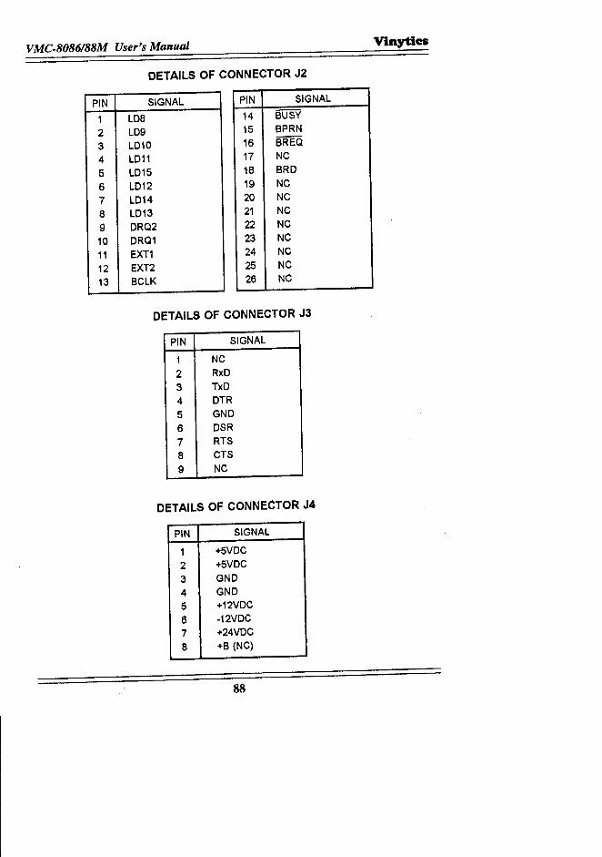
VMC.8086188M User's Manl«J1 Vinytics
DETAILS OF CONNECTOR J2
PIN SIGNAL1 LDa2 LD93 LD104 LD115 LD156 LD127 LD148 LD139 DRQ210 DRQ111 EXT112 EXT213 BCLK
PIN SIGNAL14 BUSY15 BPRN16 BREQ17 NC18 BRD19 NC20 NC21 NC22 NC23 NC24 NC25 NC26 NC
DETAILS OF CONNECTOR J3
PIN SIGNAL1 NC2 RxD3 TxD4 DTR5 GND6 DSR7 RTSa CTS9 NC
DETAILS OF CONNECTOR J4
PIN SIGNAL1 +5VDC2 +5VDC3 GND4 GND5 +12VDC6 -12VDC7 +24VDCa +B (NC)
88
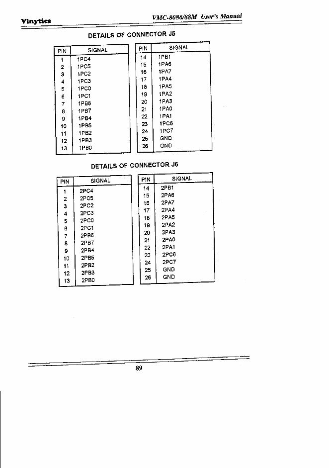
Vinytics VMC.8086188M User's Manual
DETAILS OF CONNECTOR J5
PIN SIGNAL1 1PC42 1PC53 1PC24 1PC35 1PCO6 1PC17 1PB68 1PB79 1PB410 1PB511 1PB212 1PB313 1PBO
PIN SIGNAL14 1PB115 1PA616 1PA717 1PA418 1PA519 1PA220 1PA321 1PAO22 1PA123 1PC624 1PC725 GND26 GND
DETAILS OF CONNECTOR J6
PIN SIGNAL1 2PC42 2PC53 2PC24 2PC35 2PCO6 2PC17 2PB68 2PB79 2PB410 2PB511 2PB212 2PB313 2PBO
PIN SIGNAL14 2PB115 2PA616 2PA717 2PA418 2PA519 2PA220 2PA321 2PAO22 2PA123 2PC624 2PC725 GND26 GND
89
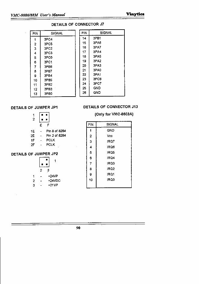
VMC-8086/88M User's Manual V"mytics
DETAILS OF CONNECTOR J7
PIN SIGNAL
1 3PC4
2 3PC5
3 3PC2
4 3PC3
5 3PCO
6 3PC1
7 3PB6
8 3PB79 3PB410 3PB5
11 3PB2
12 3PB3
13 3PBO
DETAILS OF JUMPER JP1
1
~2 ••E F
1E Pin 8 of 8284
2E Pin 2 of 8284
1F PCLK
2F PCLK
DETAILS OF JUMPER JP2
[JJ2 3
1 +24VP2 +24VDC3 +21VP
PIN SIGNAL
14 3PB115 3PA6
16 3PA717 3PA4
18 3PA5
19 3PA2
20 3PA321 3PAO22 3PA123 3PC624 3PC725 GND26 GND
DETAILS OF CONNECTOR J13
(Only for VMC-8603A)
PIN SIGNAL
1 GND
2 Vee
3 IRQ7
4 IRQ6
5 IRQ5
6 IRQ4
7 IRQ3
8 IRQ2
9 IRQ1
10 IRQO
90

Vinytics VMC·8086188M User's Manual
DETAILS OF JUMPER JP3
~1: : IGH
1G Pin 28 of MEM2, MEM42G RAMCBK1H A142H NC
DETAILS OF JUMPER JP4
~r::l5~
G H
3G NC4G RAMBK5G NC3H RAMCBK4H Pin 30 of MEM2, MEM45H +5VOC
DETAILS OF JUMPER JP5
6~7~
GH
6G RAMBK7G Pin 32 of MEM2, MEM46H NC7H +5VOC
DETAILS OF JUMPER JP6
~I: : IC 0
1C BPRN2C BPRN10 GNO20 NC
91
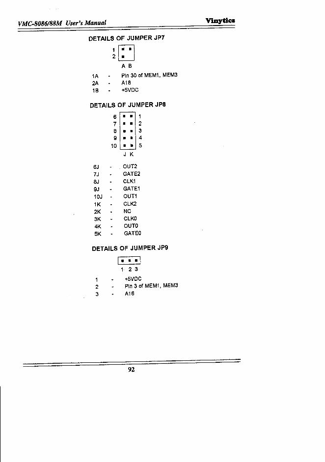
VMC-8086188M User's Manual Vinytia
DETAILS OF JUMPER JP7
~~A B
1A Pin 30 of MEM1, MEM32A A1816 +5VDC
DETAILS OF JUMPER JP8
6 • • 17 • • 28 • • 39 •• 4
10 •• 5J K
6J . OUT27J GATE28J CLK19J GATE110J OUT11K CLK22K NC3K CLKO4K OUTO5K GATED
DETAILS OF JUMPER JP9
I·• ·11 2 3
1 +5VDC2 Pin 3 of MEM1, MEM33 A16
92
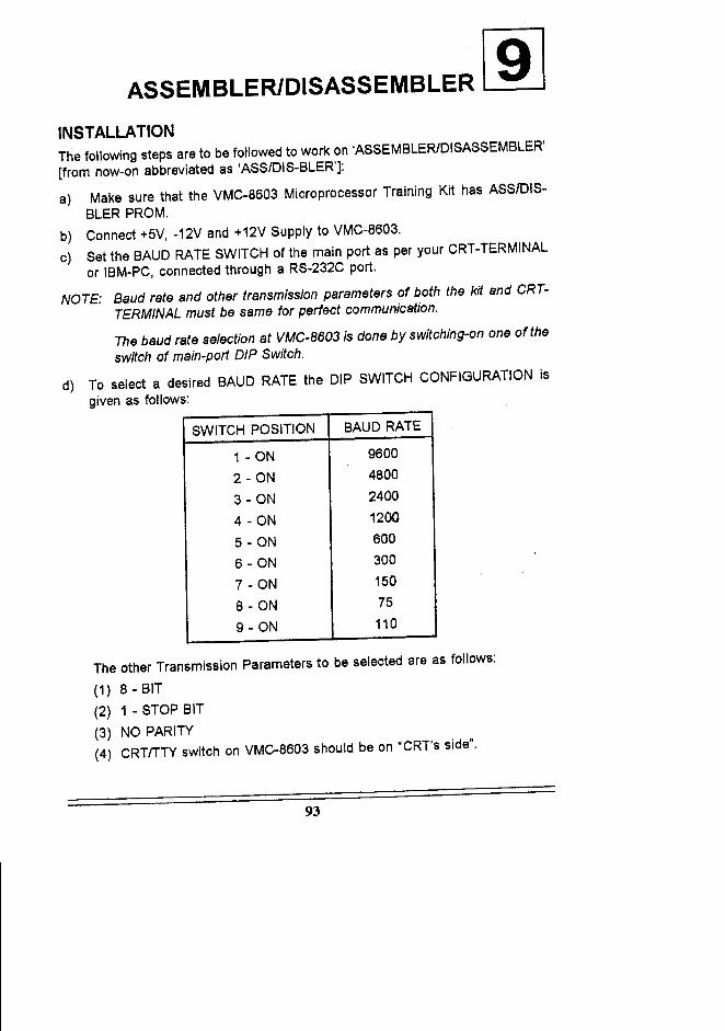
ASSEMBLER/DISASSEMBLER 191INSTALLATIONThe following steps are to be followed to work on 'ASSEMBLER/DISASSEMBLER'[from now-on abbreviated as 'ASSIDIS-BLER']:
a) Make sure that the VMC-8603 Microprocessor Training Kit has ASS/DIS-BLER PROM.
b) Connect +5V, -12V and +12V Supply to VMC-8603.c) Set the BAUD RATE SWITCH of the main port as per your CRT-TERMINAL
or IBM-PC, connected through a RS-232C port.
NOTE: Baud rate and other transmission parameters of both the kit and CRT-TERMINAL must be same for perfect communication.
The baud rate selection at VMC-8603 is done by switching-on one of theswitch of main-port DIP Switch.
d) To select a desired BAUD RATE the DIP SWITCH CONFIGURATION isgiven as follows:
SWITCH POSITION BAUD RATE
1 - ON 9600
2 - ON 4800
3 - ON 2400
4 - ON 1200
5 - ON 600
6 - ON 300
7 - ON 150
8 - ON 75
9 - ON 110
The other Transmission Parameters to be selected are as follows:
(1) 8 - BIT(2) 1 - STOP BIT(3) NO PARITY(4) CRTITTY switch on VMC-8603 should be on "CRT's side".
93
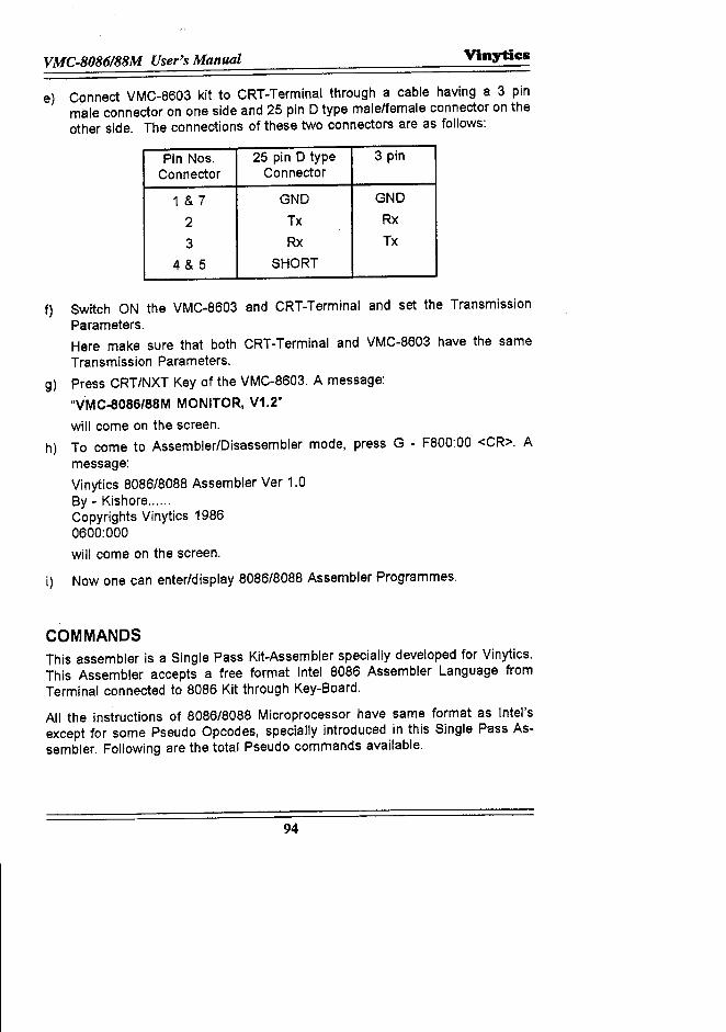
VMC.8086188M User's Manual Vinytics
e) Connect VMC-8603 kit to CRT-Terminal through a cable having a 3 pinmale connector on one side and 25 pin D type male/female connector on theother side. The connections of these two connectors are as follows:
Pin Nos. 25 pin D type 3 pinConnector Connector
1 & 7 GND GND
2 Tx Rx
3 Rx Tx
4&5 SHORT
f) Switch ON the VMC·8603 and CRT-Terminal and set the TransmissionParameters.Here make sure that both CRT-Terminal and VMC-8603 have the sameTransmission Parameters.
g) Press CRT/NXT Key of the VMC-8603. A message:"VMC-8086/88M MONITOR, V1.2"will come on the screen.
h) To come to Assembler/Disassembler mode, press G - F800:00 <CR>. Amessage:Vinytics 8086/8088 Assembler Ver 1.0By - Kishore .Copyrights Vinytics 19860600:000will come on the screen.
i) Now one can enter/display 8086/8088 Assembler Programmes.
COMMANDSThis assembler is a Single Pass Kit-Assembler specially developed for Vinytics.This Assembler accepts a free format Intel 8086 Assembler Language fromTerminal connected to 8086 Kit through Key-Board.
All the instructions of 8086/8088 Microprocessor have same format as Intel'sexcept for some Pseudo Opcodes, specially introduced in this Single Pass As-sembler. Following are the total Pseudo commands available.
94
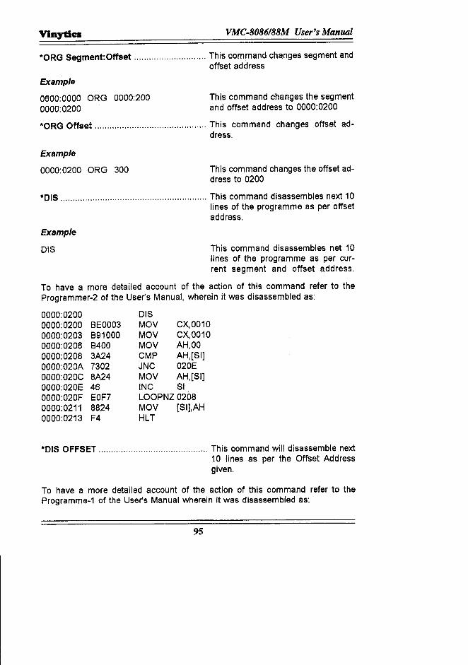
Vinytics VMC·8086188M User's Manual
*ORG Segment:Offset This command changes segment andoffset address
Example
0600:0000 ORG 0000:2000000:0200
This command changes the segmentand offset address to 0000:0200
*ORG Offset This command changes offset ad-dress.
Example
0000:0200 ORG 300 This command changes the offset ad-dress to 0200
*OIS This command disassembles next 10lines of the programme as per offsetaddress.
Example
DIS This command disassembles net 10lines of the programme as per cur-rent segment and offset address.
To have a more detailed account of the action of this command refer to theProgrammer-2 of the User's Manual, wherein it was disassembled as:
0000:02000000:0200 8E00030000:0203 8910000000:0206 84000000:0208 3A240000:020A 73020000:020C 8A240000:020E 460000:020F EOF70000:0211 88240000:0213 F4
DISMOV CX,0010MOV CX,0010MOV AH,OOCMP AH,[SI)JNC 020EMOV AH,[SI)INC SILOOPNZ0208MOV [SI),AHHLT
*OIS OFFSET This command will disassemble next10 lines as per the Offset Addressgiven.
To have a more detailed account of the action of this command refer to theProgramme-1 of the User's Manual wherein it was disassembled as:
95
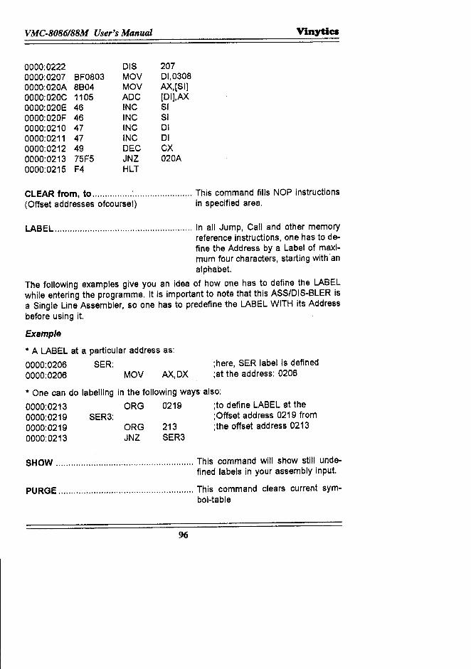
VMC-8086/88M User's Manual Vinytics
0000:02220000:0207 BF08030000: 020A 8B040000: 020C 11050000:020E 460000:020F 460000:0210 470000:0211 470000:0212 490000:0213 75F50000:0215 F4
015MOVMOVAOCINCINCINCINCOECJNZHLT
20701,0308AX,[SI][OI],AX51510101CX020A
CLEAR from, to This command fills NOP instructions(Offset addresses of course!) in specified area.
LABEL In all Jump, Call and other memoryreference instructions, one has to de-fine the Address by a Label of maxi-mum four characters, starting with 'analphabet.
The following examples give you an idea of how one has to define the LABELwhile entering the programme. It is important to note that this ASS/OIS-BLER isa Single Line Assembler, so one has to predefine the LABEL WITH its Addressbefore using it.
Example
•• A LABEL at a particular address as:
0000: 0206 SER:0000:0206 MOV AX,OX
;here, SER label is defined;at the address: 0206
•• One can do labelling in the following ways also:
0000:0213 ORG 0219 ;to define LABEL at the0000:0219 SER3: ;Offset address 0219 from0000:0219 ORG 213 ;the offset address 02130000:0213 JNZ SER3
SHOW This command will show still unde-fined labels in your assembly input.
PURGE This command clears current sym-bol-table
96
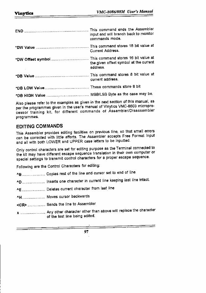
Vinyties VMC-8086/88M User's Manual
END This command ends the Assemblerinput and will branch back to monitorcommands mode.
"OW Value This command stores 16 bit value atCurrent Address.
"OW Offset symbol This command stores 16 bit value atthe given offset symbol at the currentaddress.
"DB Value This command stores 8 bit value atcurrent address.
"DB LOW Value These commands store 8 bit
"DB HIGH Value MSB/LSB Byte as the case may be.
Also please refer to the examples as given in the next section of this manual, asper the programmes given in the user's manual of Vinytics VMC-8603 micropro-cessor training kit, for different commands of Assembler/Disassemblerprogrammes.
EDITING COMMANDSThis Assembler provides editing facilities on previous line, so that small errorscan be corrected with little efforts. The Assembler accepts Free Format Inputand all with both LOWER and UPPER case letters to be inputted.
Only control characters are set for editing purpose as the Terminal connected tothe kit may have different escape sequence translation in their own computer orspecial settings to transmit control characters for a proper escape sequence.
Following are the Control Characters for editing:
I\B Copies rest of the line and cursor set to end of line
1\0 .•.•.....•........••. Inserts one character in current line keeping last line intact.
I\E ..........•.......... Deletes current character from last line
I\H ••••••..••••••.••.... Moves cursor backwards
<CR> Sends the line to Assembler
x Any other character other than above will replace the characterof the last line being edited:
97
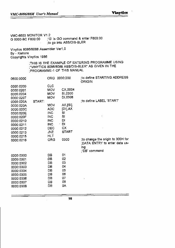
VMC.8086188M User's Manual Vinytics .
VMC-8603 MONITOR V1.2G OOOO-BCF800:00 ;'G' is GO command & enter F800:00
;to go into ASS/DIS-BLER
Vinytics 8086/8088 Assembler Ver1.0By - KishoreCopyrights Vinytics 1986
;THIS IS THE EXAMPLE OF ENTERING PROGRAMME USING;"VINYTICS 8086/8088 ASSIDIS-BLER" AS GIVEN IN THE;PROGRAMME-1 OF THIS MANUAL
0600:0000 ORG 0000:200
0000:0200 CLC0000:0201 MOV CX,00040000:0204 MOV 81,03000000:0207 MOV 01,03080000:020A START:0000:020A MOV AX,[SI]0000:020C ADC [DI],AX0000:020E INC SI0000:020F INC SI0000:0210 INC 010000:0211 INC 010000:0212 DEC CX0000:0213 JNZ START0000:0215 HLT0000:0216 ORG 0300
0000:0300 DB 010000:0301 DB 020000:0302 DB 030000:0303 DB 040000:0304 DB 050000:0305 DB 060000:0306 DB 070000:0307 DB 080000:0308 DB OA
98
;to define STARTING ADDRESSORIGIN
;to define LABEL 'START'
;to change the origin to 300H for;DATA ENTRY to enter data us-ing;'DB' command
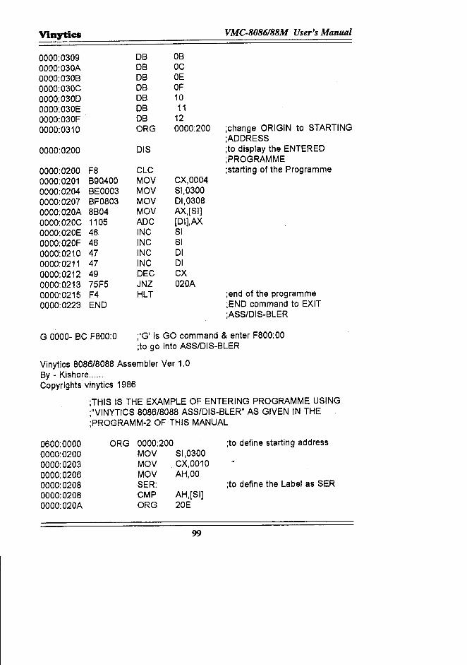
Vinytics VMC·8086188M User's Manual
0000:0309 DB OB0000:030A DB OC0000:030B DB OE0000:030C DB OF0000:0300 DB 100000:030E DB 110000:030F DB 120000:0310 ORG 0000:200 ;change ORIGIN to STARTING
;AOORESS0000:0200 DIS ;to display the ENTERED
;PROGRAMME0000:0200 F8 CLC ;starting of the Programme0000:0201 B90400 MOV CX,00040000:0204 BEOO03 MOV SI,03000000:0207 BF0803 MOV 01,03080000:020A 8B04 MOV AX,[SI]0000:020C 1105 AOC [OI],AX0000:020E 46 INC SI0000:020F 46 INC SI0000:0210 47 INC 010000:0211 47 INC 010000:0212 49 DEC CX0000:0213 75F5 JNZ 020A0000:0215 F4 HLT ;end of the programme0000:0223 END ;ENO command to EXIT
;ASS/OIS-BLER
G 0000- BC F800:0 ;'G' is GO command & enter F800:00;to go into ASS/OIS-BLER
Vinytics 8086/8088 Assembler Ver 1.0By - Kishore......Copyrights vinytics 1986
;THIS IS THE EXAMPLE OF ENTERING PROGRAMME USING;"VINYTICS 8086/8088 ASS/OIS-BLER" AS GIVEN IN THE;PROGRAMM-2 OF THIS MANUAL
0600:00000000:02000000:02030000:02060000:02080000:02080000:020A
ORG 0000:200 ;to define starting addressMOV SI,0300MOV CX,0010MOV AH,OOSER: ;to define the Label as SERCMP AH,[SI]ORG 20E
99
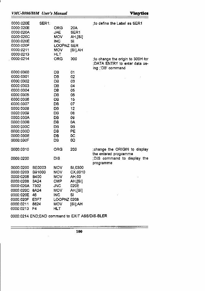
VMC·8086188M User's Manual VinytlC8
0000:020E SER1: ;to define the Label as SER10000:020E ORG 20A0000:020A JAE SER10000:0'20C MOV AH,[SI)00OO:020E INC SI0000:020F LOOPNZ SER0000:0211 MOV [SI],AH0000:0213 HLT
. 0000:0214 ORG 300 ;to change the origin to 300H for;OATA ENTRY to enter data us-ing ;'DB' command
0000:0300 DB 010000:0301 DB 020000:0302 DB 030000:0303 DB 040000:0304 DB 050000:0305 DB 060000:0306 DB 150000:0307 DB 070000:0308 DB 120000:0309 DB 08000O:030A DB 090000:030B DB OA0000:030C DB OB0000:0300 DB PE0000:030E DB OCOOoo:030F DB 00
0000:0310 ORG 200 ;change the ORIGIN to displaythe entered programme
0000:0200 DIS ;DIS command to display theprogramme
0000:0200 BEOO03 MOV SI,03000000:0203 B91000 MOV CX,00100000:0206 B400 MOV AH,OO0000:0208 3A24 CMP AH,[SIJ0000:020A 7302 JNC 020E000O:020C 8A24 MOV AH,[SIJ0000:020E 46 INC SIOOOO:020F EOF7 LOOPNZ 02080000:0211 8824 MOV [SI],AH0000:0213 F4 HLT
0000:0214 END;END command to EXIT ASS/DIS-BLER
100
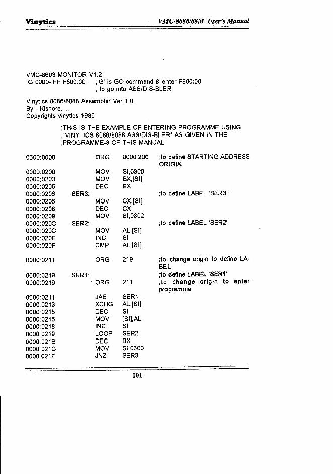
Vinytics VMC·8086188M User's Manual
VMC·8603 MONITOR V1.2,G 0000· FF F800:00 ;'G' is GO command & enter F800:00
; to go into ASS/DIS-BLER
Vinytics 8086/8088 Assembler Ver 1.0By - Kishore.....Copyrights vinytics 1986
;THIS IS THE EXAMPLE OF ENTERING PROGRAMME USING;"VINYTICS 8086/8088 ASS/DIS·BLERu AS GIVEN IN THE;PROGRAMME-3 OF THIS MANUAL
0600:0000 ORG 0000:200
0000:0200 MOV 81,03000000:0203 MOV BX,[8I)0000:0205 DEC BX0000:0206 SER3:0000:0206 MOV CX,[SIJ0000:0208 DEC CX0000:0209 MOV SI,03020000:020C SER2:0000:020C MOV AL,[Slj0000:020E INC SI0000:020F CMP AL,[Slj
0000:0211 ORG 219
0000:0219 SER1:0000:0219 ORG 211
0000:0211 JAE SER10000:0213 XCHG AL,[SI)0000:0215 DEC SI0000:0216 MOV [Slj,AL0000:0218 INC SI0000:0219 LOOP SER20000:021B DEC BX0000:021C MOV SI,0300000O:021F JNZ SER3
101
;to define STARTING ADDRESSORIGIN
;to define LABEL 'SER3'
;to define LABEL 'SER2'
;to change origin to define LA·BEL;to define LABEL 'SER1';to change origin to enterprogramme
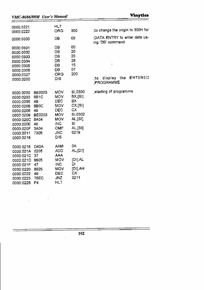
VMC.8086/88M User's Manual Vinytics
0000:0221 HLT0000:0222 ORG 300 ;to change the origin to 300H for
0000:0300 DB 05 ;DATA ENTRY to enter data us-ing 'DB' command
0000:0301 DB 000000:0302 DB 200000:0303 DB 250000:0304 DB 280000:0305 DB 150000:0306 DB 070000:0307 ORG 2000000:0200 DIS ;to display the ENTERED
;PROGRAMME
0000:0200 BEOO03 MOV SI,0300 ;starting of programme0000:0203 8B1C MOV BX,[SI]0000:0205 4B DEC BX0000:0206 8BOC MOV CX,[SI]0000:0208 49 DEC CX0000:0209 BE0203 MOV SI,03020000:020C 8A04 MOV AL,[Slj0000:020E 46 INC SI0000:020F 3A04 CMP AL,[Slj0000:0211 7306 JNC 02190000:0218 DIS
0000:0218 D40A AAM OA0000:021A 0205 ADD AL,[Dlj0000:021C 37 AAA0000:0210 8805 MOV [Dlj,AL0000:021F 47 INC 010000:0220 8825 MOV [Dlj,AH0000:0222 49 DEC CX0000:0223 75EC JNZ 02110000:0225 F4 HLT
102
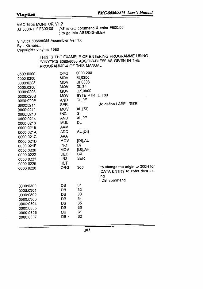
Vinytics VMC·8086188M User's Manual
VMC-8603 MONITOR V1.2.G 0000- FF F800:00 ;'G' is GO command & enter F800:00
; to go into ASS/DIS-BLER
Vinytics 8086/8088 Assembler Ver 1.0By - Kishore .....Copyrights vinytics 1986
;THIS IS THE EXAMPLE OF ENTERING PROGRAMME USING;"VINYTICS 8086/8088 ASS/DIS-BLER" AS GIVEN IN THE;PROGRAMME-4 OF THIS MANUAL
0600:00000000:02000000:02030000:02060000:02080000:020B0000:020E0000:02110000:02110000:02130000:02140000:02160000:02180000:021A0000:021C0000:02100000:021F0000:02200000:02220000:02230000:02250000:0226
ORGMOVMOVMOVMOVMOVANDSER:MOVINCANDMULAAMADDAMMOVINCMOVDECJNZHLTORG
0000:03000000:03010000:03020000:03030000:03040000:03050000:03060000:0307
DBDBDBDBDBDBDBDB·
0000:200SI,030001,0308DL,34CX,0800BYTE PTR [01),00DL,OF
;to define LABEL 'SER'AL,[SI]SIAL,OFDL
AL,[DI]
[DI],AL01[DI],AHCXSER
300 ;to change the origin to 300H for;DATA ENTRY to enter data us-ing;'DB' command
3132333435363132
103
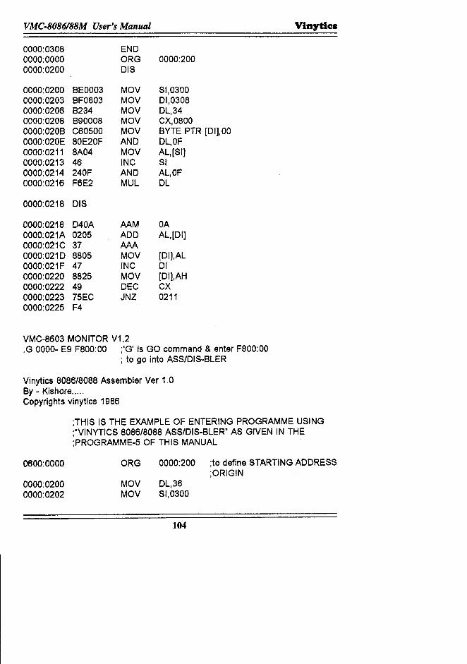
VMC·8086188M User's Manual Vinytics
0000:0308 END0000:0000 ORG 0000:2000000:0200 DIS
0000:0200 BEOO03 MOV SI,03000000:0203 BF0803 MOV 01,03080000:0206 B234 MOV DL,340000:0208 B90008 MOV CX,08000000:020B C60S00 MOV BYTE PTR [DI],OO0000:020E 80E20F AND DL,OF0000:0211 8A04 MOV AL,[SI}0000:0213 46 INC SI0000:0214 240F AND AL,OF0000:0216 F6E2 MUL DL
0000:0218 DIS
0000:0218 D40A AAM OAOOOO:021A0205 ADD AL,[DI]0000:021C 37 AAA0000:0210 8805 MOV [DI],AL0000:021F 47 INC 010000:0220 8825 MOV [DI],AH0000:0222 49 DEC CX0000:0223 7SEC JNZ 02110000:0225 F4
VMC-8603 MONITOR V1.2.G OOOO~E9 F800:00 ;'G' is GO command & enter F800:00
; to go into ASS/DIS-BLER
Vinytics 8086/8088 Assembler Ver 1.0By - Kishore .....Copyrights vinytics 1986
0600:0000
;THIS IS THE EXAMPLE OF ENTERING PROGRAMME USING;"VINYTICS 8086/8088 ASS/DIS-BLER" AS GIVEN IN THE;PROGRAMME-5 OF THIS MANUAL
ORG 0000:200 ;to define STARTING ADDRESS;ORIGIN
0000:02000000:0202
MOV DL,36MOV SI,0300
104
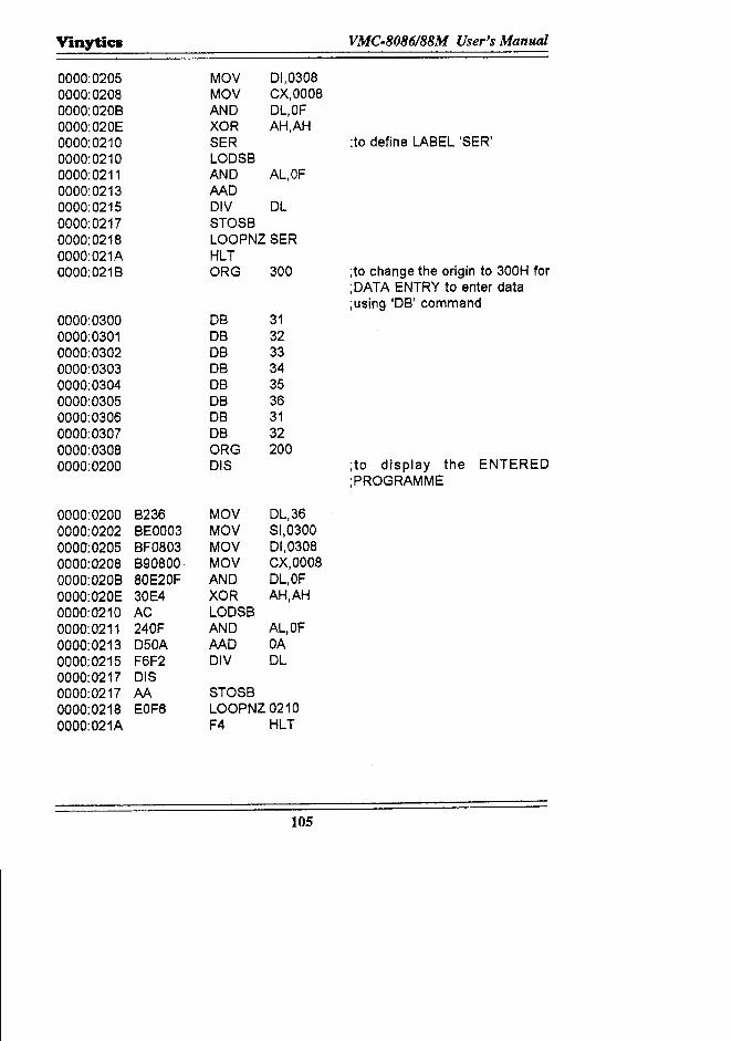
Vinytics VMC·8086188M User's Manual
0000:0205 MOV 01,03080000:0208 MOV CX,00080000:020B AND DL,OF0000:020E XOR AH,AH0000:0210 SER ;to define LABEL 'SER'0000:0210 LODSB0000:0211 AND AL,OF0000:0213 AAD0000:0215 DIV DL0000;0217 STOSB0000;0218 LOOPNZ SER0000:021A HLT0000:021B ORG 300 ;to change the origin to 300H for
;OAT A ENTRY to enter data;using 'DB' command
0000:0300 DB 310000:0301 DB 320000:0302 DB 330000:0303 DB 340000:0304 DB 350000;0305 DB 360000:0306 DB 310000;0307 DB 320000;0308 ORG 2000000:0200 DIS ;to display the ENTERED
;PROGRAMME
0000:0200 B236 MOV DL,360000:0202 BEOO03 MOV SI,03000000;0205 BF0803 MOV 01,03080000:0208 B90800 MOV CX,00080000:020B 80E20F AND DL,OF0000:020E 30E4 XOR AH,AH0000:0210 AC LODSB0000:0211 240F AND AL,OF0000:0213 D50A AAD OA0000:0215 F6F2 DIV DL0000:0217 DIS0000:0217 AA STOSB0000:0218 EOF6 LOOPNZ 021000OO:021A F4 HLT
105
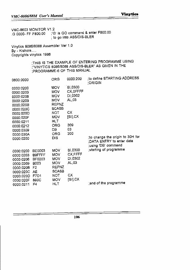
VMC-8086/88M User's Manual V'mytia
VMC-8603 MONITOR V1.2.G 0000- FF F800:00 ;'G' is GO command & enter F800:00
; to go into ASS/DIS-BLER
Vinytics 8086/8088 Assembler Ver 1.0By - Kishore.....Copyrights vinytics 1986
;THIS IS THE EXAMPLE OF ENTERING PROGRAMME USING;"VINYTICS 8086/8088 ASS/DIS-BLER" AS GIVEN IN THE;PROGRAMME-6 OF THIS MANUAL
0600:0000 ORG 0000:200 ;to define STARTING ADDRESS;ORIGIN
0000:0200 MOV SI,03000000:0203 MOV CX,OFFFF0000:0206 MOV 01,03020000:0209 MOV AL,030000:020B REPNZ0000:020C SCASB0000:0200 NOT CX0000:020F MOV [Slj,CX0000:0211 HLT0000:0212 ORG 3090000:0309 DB 030000:030A ORG 2000000:0200 DIS ;to change the origin to 30H for
;OATA ENTRY to enter data;using 'DB' command
0000:0200 BEOO03 MOV 81,0300 ;starting of programme0000:0203 B9FFFF MOV CX,FFFF0000:0206 BF0203 MOV 01,03020000:0209 B003 MOV AL,030000:020B F2 REPNZ0000:020C AE SCASB0000:0200 F7D1 NOT CX0000:020F 890C MOV [Slj,CX0000:0211 F4 HLT ;end of the programme
106
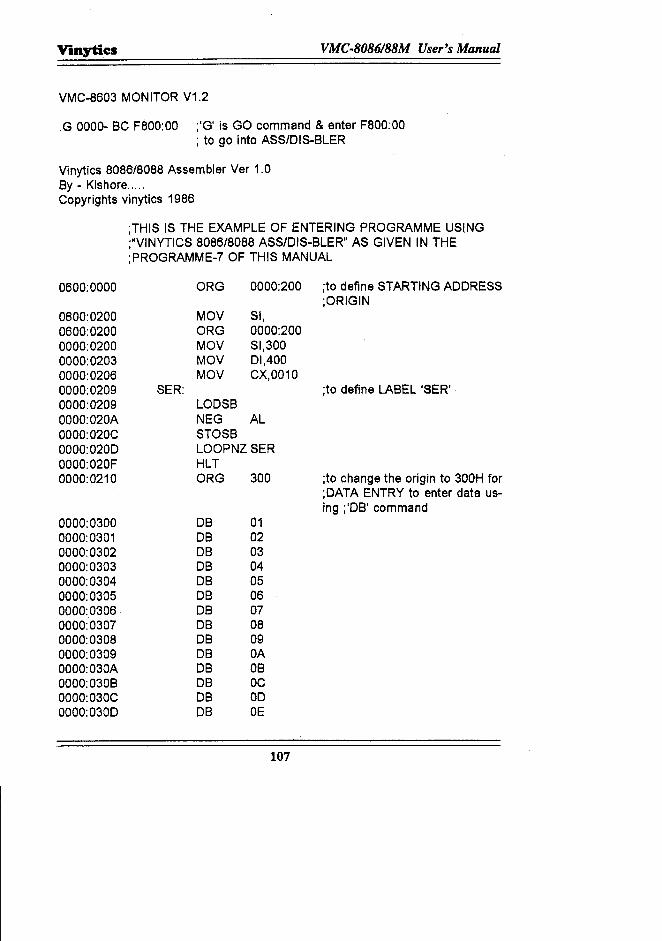
Vinytics VMC·8086188M User's Manual
VMC-8603 MONITOR V1.2
.G 0000- BC F800:00 ;'G' is GO command & enter F800:00; to go into ASS/DIS-BLER
Vinytics 8086/8088 Assembler Ver 1.0By - Kishore.....Copyrights vinytics 1986
;THIS IS THE EXAMPLE OF ENTERING PROGRAMME USING;"VINYTICS 8086/8088 ASS/DIS-BLER" AS GIVEN IN THE;PROGRAMME-7 OF THIS MANUAL
0600:0000 ORG 0000:200 ;to define STARTING ADDRESS;ORIGIN
0600:0200 MOV 51,0600:0200 ORG 0000:2000000:0200 MOV SI,3000000:0203 MOV 01,4000000:0206 MOV CX,00100000:0209 SER: ;to define LABEL 'SER'0000:0209 LOD5B0000:020A NEG AL0000:020C STOSB0000:0200 LOOPNZ SER0000:020F HLT0000:0210 ORG 300 ;to change the origin to 300H for
;DATA ENTRY to enter data us-ing ;'DB' command
0000:0300 DB 010000:0301 DB 020000:0302 DB 030000:0303 DB 040000:0304 DB 050000:0305 DB 060000:0306 DB 070000:0307 DB 080000:0308 DB 090000:0309 DB OA0000:030A DB OB0000:030B DB DC000O:030C DB 000000:0300 DB DE
107
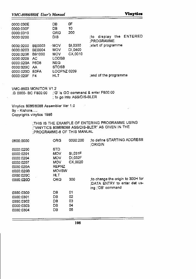
VMC·8086188M User's Manual Vinytics
0000:030E0000:030F0000:03100000:0200
DB OFDB 10oRG 200DIS
0000:0200 BE00030000:0203 BE00040000:0206 B910000000:0209 AC0000:020A F6D80000:020C AA0000:0200 EOFA0000:020F F4
·MoVMoVMoVLoDSBNEGSToSBLooPNZ 0209HLT
SI,030001,0400CX,0010
;to display the ENTERED;PRoGRAMME;start of programme
;end of the programme
VMC-8603 MONITOR V1.2.G 0000- BCF800:00 ;'G' is GO command & enter F800:00
; to go into ASS/DIS-BLER
Vinytics 8086/8088 Assembler Ver 1.0By - Kishore.....Copyrights vinytics 1986
;THIS IS THE EXAMPLE OF ENTERING PROGRAMME USING;"VINYTICS 808618088 ASS/DIS-BLER" AS GIVEN IN THE;PRoGRAMME-8 OF THIS MANUAL
0600:0000 oRG 0000:200 ;to define STARTING ADDRESS;ORIGIN
0000:0200 STD0000:0201 MOV SI,031F0000:0204 MoV DI,032F0000:0207 MOV CX,00200000:020A REPNZ0000:020B MoVSW0000:020C HLT0000:0200 oRG 300 ;to change the origin to 300H for
;DATA ENTRY to enter dat us-ing ;'DB' command
0000:0300 DB 010000:0301 DB 020000:0302 DB 030000:0303 DB 040000:0304 DB 05
108
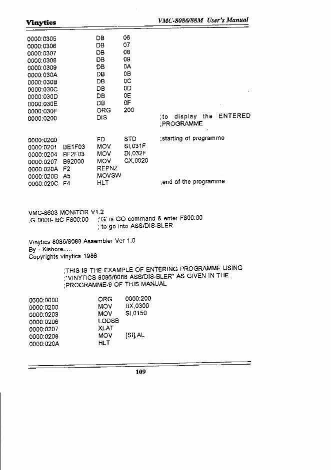
Viaytics VMC.8086188M User's Manual
0000:0305 DB 060000:0306 DB 070000:0307 DB 080000:0308 DB 090000:0309 DB OA0000:030A DB OB0000:030B DB OC0000:030C DB 000000:0300 DB OE0000:030E DB OF0000:030F ORG 2000000:0200 DIS ;to display the ENTERED
;PROGRAMME
0000:0200 FD STD ;starting of programme0000:0201 BE1F03 MOV SI,031F0000:0204 BF2F03 MOV DI,032F0000:0207 892000 MOV CX,00200000:020A F2 REPNZ0000:0208 A5 MOVSW0000:020C F4 HLT ;end of the programme
VMC-8603 MONITOR V1.2.G 0000- BC F800:00 ;'G' is GO command & enter FSOO:OO
; to go into ASS/DIS-8LER
Vinytics S086/S088 Assembler Ver 1.08y - Kishore.....Copyrights vinytics 1986
;THIS IS THE EXAMPLE OF ENTERING PROGRAMME USING;"VINYTICS 8086/S0SS ASSIDIS-BLER" AS GIVEN IN THE;PROGRAMME-9 OF THIS MANUAL
0600:0000 ORG 0000:2000000:0200 MOV BX,03000000:0203 MOV SI,01500000:0206 LODSB0000:0207 XLAT0000:0208 MOV [SI1.AL0000:020A HLT
109
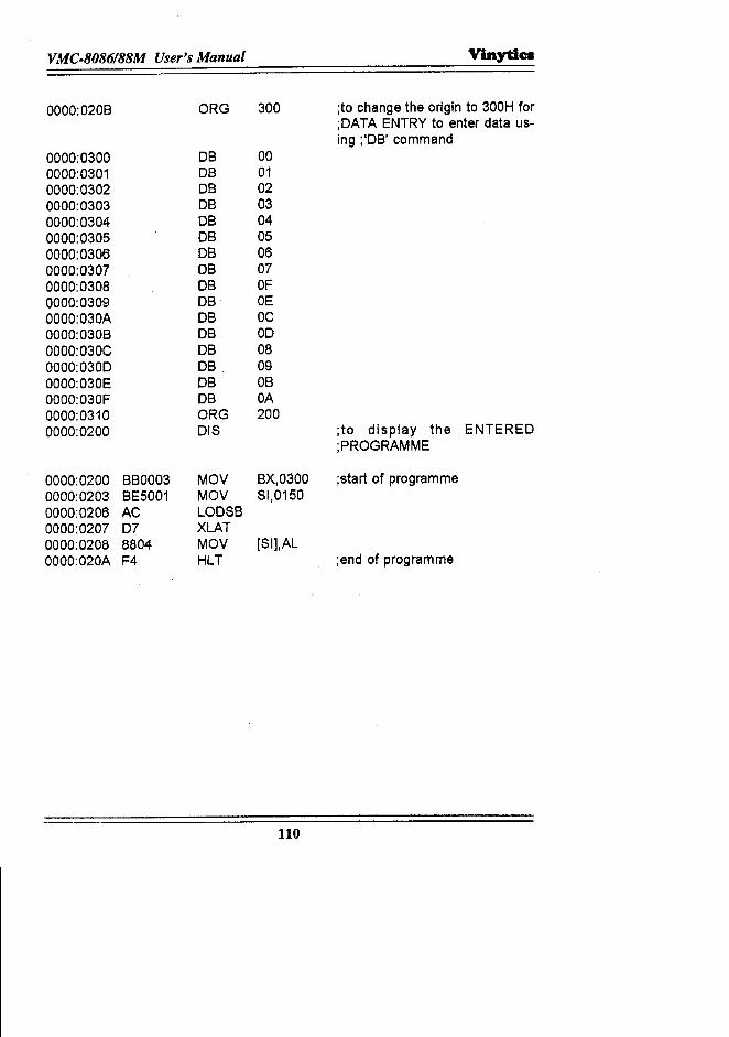
110
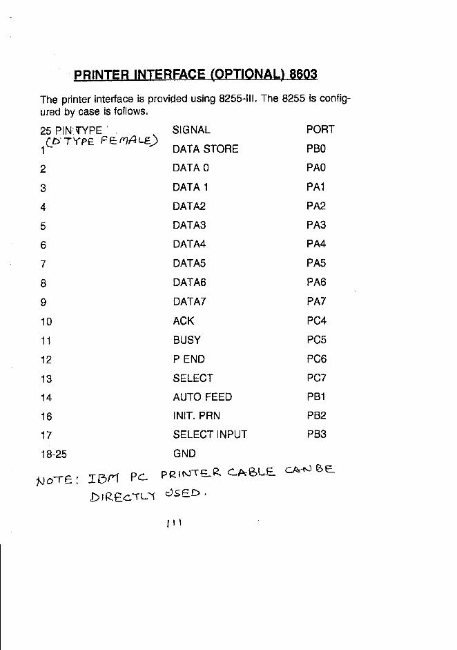
PRINTER INTERFACE (OPTIONAL) 8603
The printer interface is provided using 8255-111.The 8255 is config-ured by case is follows.
25 PIN"'l"YPE'." SIGNALCP"7YPE PE:fY1ALi:.)1 DATA STORE
2 DATA 03 DATA 14 DATA25 DATA36 DATA47 DATA58 DATA69 DATA710 ACK
11 BUSY
12 PEND13 SELECT14 AUTO FEED16 INIT.PRN17 SELECT INPUT18-25 GND
R G Q LE eAr--NBE..~.lo-re: IBM Pc.. PRIrSTE.. P>co
DIRE.c."TL\ c:'St=D.
PORTPBO
PAOPA1
PA2PA3PA4PA5PA6PA7PC4PC5PC6
PC7
PB1
PB2
PB3
, I ,
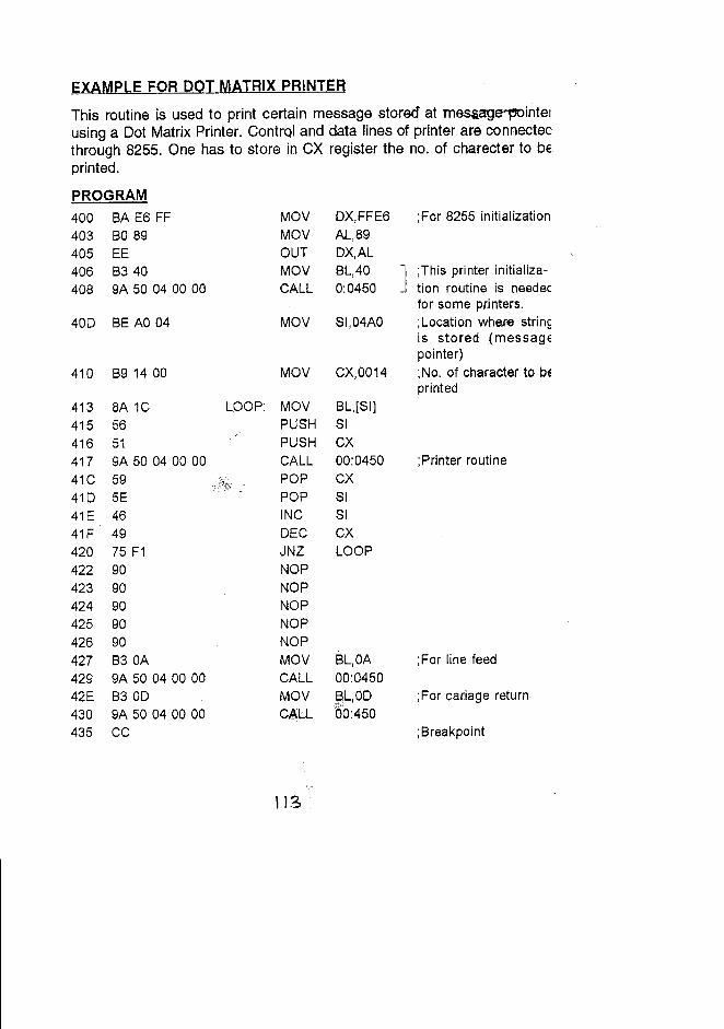
EXAMPLE FOR DOT MATRIX PRINTER
This routine is used to print certain message stored at mesaage'1'Ointelusing a Dot Matrix Printer. Control and data lines of printer are connectecthrough 8255. One has. to store in CX register the no. of charecter to beprinted.
PROGRAM400 BA E6 FF MOV OX,FFE6 ;For 8255 initialization403 BO89 MOV AL,89405 EE OUT OX,AL406 B340 MOV 8L,40 ] ;This printer initializa-408 9A 50 040000 CALL 0:0450 tion routine is oeedec
for some printers.40D 8E AO 04 MOV 51,04AO ;Location whe.re strin~
is stored (messagEpointer)
410 B9 1400 MOV CX,0014 ;No. of character to bEprinted
413 8A 1C LOOP: MOV BL,[5Ij415 56 PUSH 51416 51 PUSH CX417 9A 50040000 CALL 00:0450 ;Printer routine41C 59 POP CX41D 5E POP 5141E 46 INC SI41F 49 DEC CX420 75 F1 JNZ LOOP422 90 NOP423 90 NOP424 90 NOP425 90 NOP426 90 NOP427 830A MOV BL,OA ;For line feed429 9A 50040000 CALL 00:045042E 8300 MOV BL,OD ;For cariage return430 9A 50040000 CALL 60:450435 CC ;Breakpoint
\13
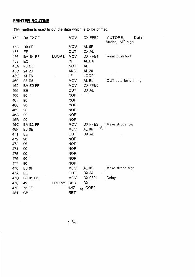
PRINTER ROUTINE
;This routine is used to out the data which is to be printed.
450 8A E2 FF MOV DX,FFE2 ;AUTOPE, DataStrobe, INIT high
453 80 OF MOV AL,OF455 EE OUT DX,AL456 8A E4 FF LOOP1: MOV DX,FFE4 ;Read busy low
459 EC IN AL,DX45A F6 DO NOT AL45C 2420 AND AL,2045E 74 F6 JZ LOOP1:460 8808 MOV AL,8L ;OUT data for printing
462 8A EO FF MOV DX,FFEO
465 EE OUT DX,AL466 90 NOP467 90 NOP468 90 NOP469 90 NOP46A 90 NOP468 90 NOP46C 8A E2 FF MOV DX,FFE2 ;Make strobe low46F 800E MOV AL,OE471 EE OUT DX,AL
472 90 NOP473 90 NOP474 90 NOP475 90 NOP476 90 NOP477 90 NOP478 80 OF MOV AL,OF ;Make strobe high
47A EE OUT DX,AL478 8901 03 MOV CX,0301 ;Delay
47E 49 LOOP2: DEC CX47F 75 FD ZlNZ :JALOOP2481 C8 RET
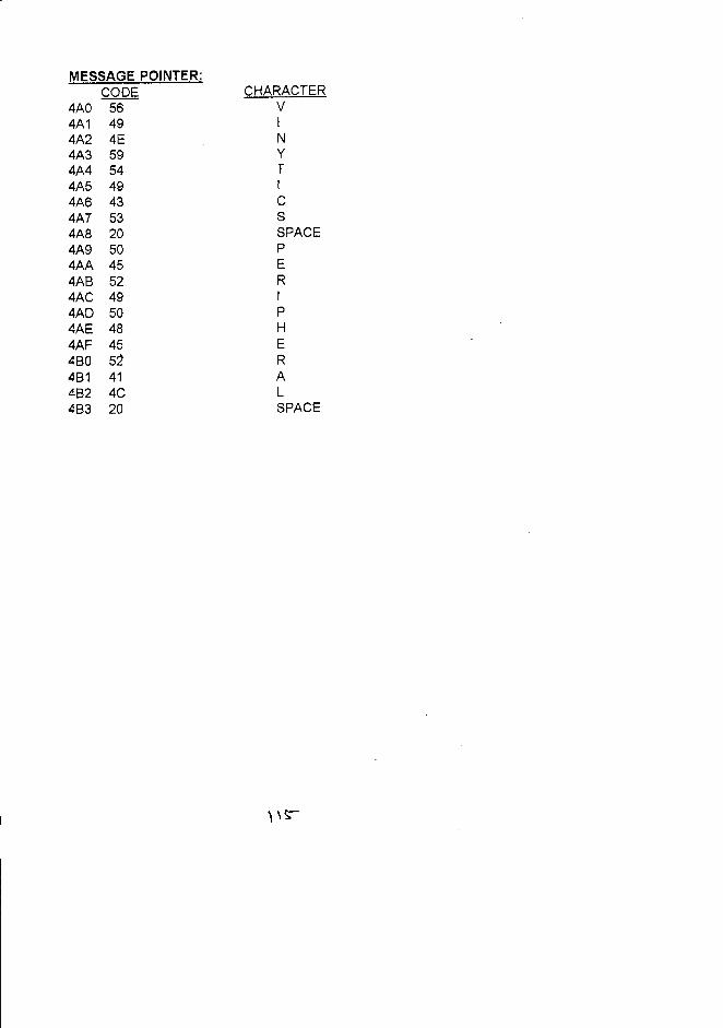
MESSAGE POINTER:CODE
4AO 564A1 494A2 4E4A3 594A4 544A5 494A6 434A7 534A8 204A9 504AA 454A8 524AC 494AD 504AE 484AF 45480 52481 41482 4C483 20
CHARACTERVINyTICSSPACEPERIPHERALSPACE
,,~