Embed Size (px)
Citation preview
hsabaghianb @ kashanu.ac.ir Microprocessors 1-
8051timer/counter
hsabaghianb @ kashanu.ac.ir Microprocessors 1-
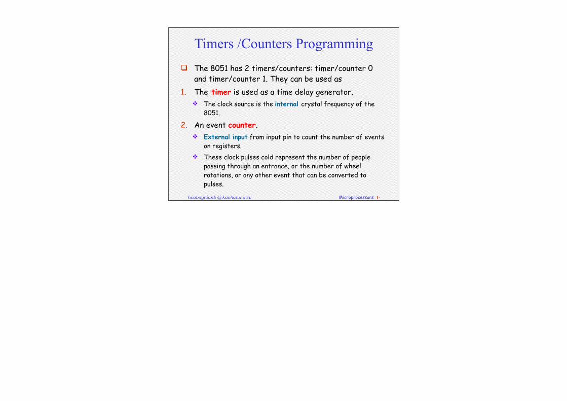
Timers /Counters Programming The 8051 has 2 timers/counters: timer/counter 0
and timer/counter 1. They can be used as1. The timer is used as a time delay generator.
The clock source is the internal crystal frequency of the 8051.
2. An event counter. External input from input pin to count the number of events
on registers. These clock pulses cold represent the number of people
passing through an entrance, or the number of wheel rotations, or any other event that can be converted to pulses.
hsabaghianb @ kashanu.ac.ir Microprocessors 1-
hsabaghianb @ kashanu.ac.ir Microprocessors 1-
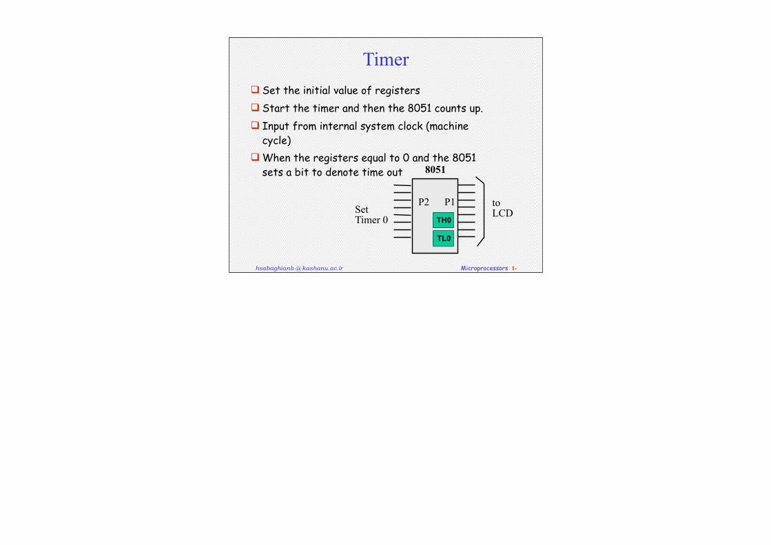
Timer Set the initial value of registers Start the timer and then the 8051 counts up. Input from internal system clock (machine
cycle) When the registers equal to 0 and the 8051
sets a bit to denote time out
toLCD
P1
8051
TL0
TH0
P2SetTimer 0
hsabaghianb @ kashanu.ac.ir Microprocessors 1-
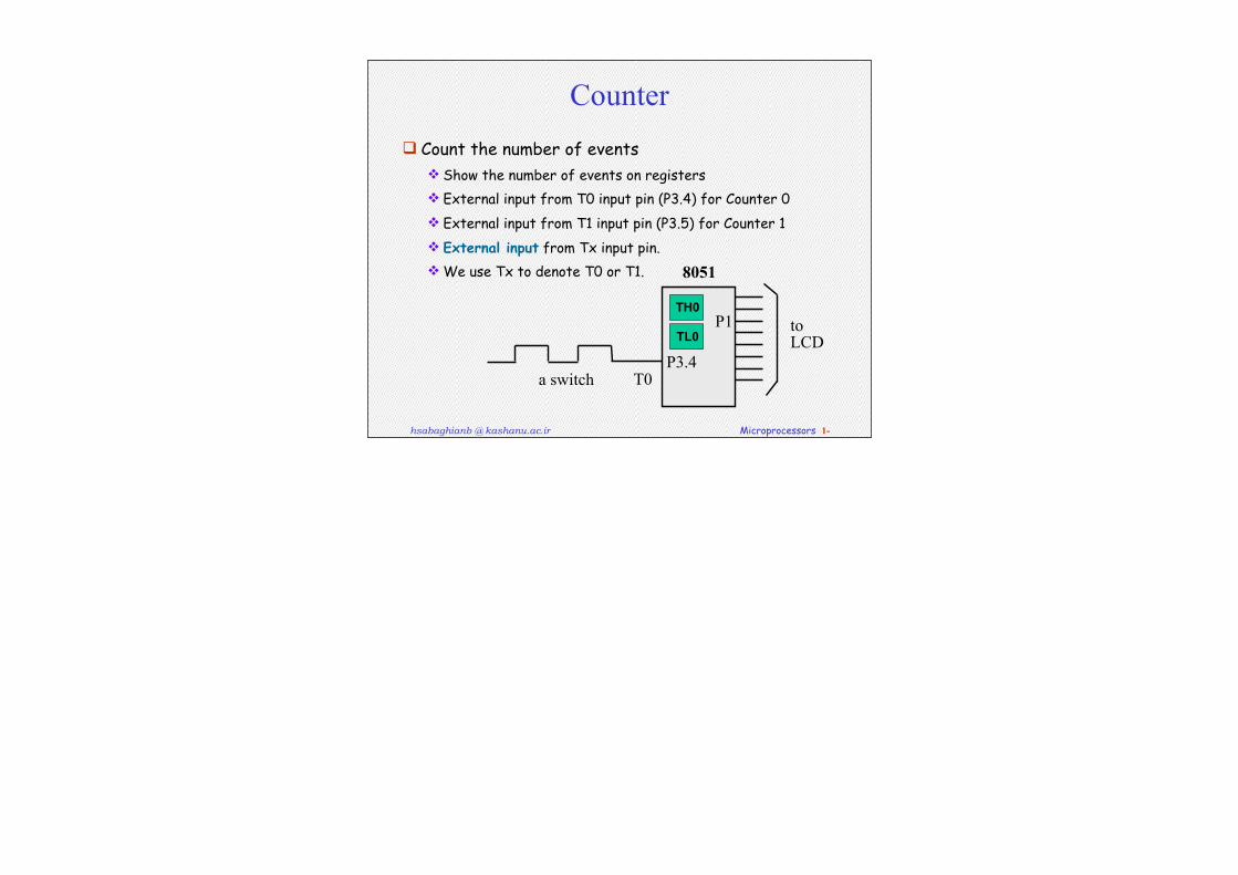
Counter Count the number of events
Show the number of events on registers External input from T0 input pin (P3.4) for Counter 0 External input from T1 input pin (P3.5) for Counter 1 External input from Tx input pin. We use Tx to denote T0 or T1.
T0
toLCD
P3.4
P1
8051
a switch
TL0
TH0
hsabaghianb @ kashanu.ac.ir Microprocessors 1-
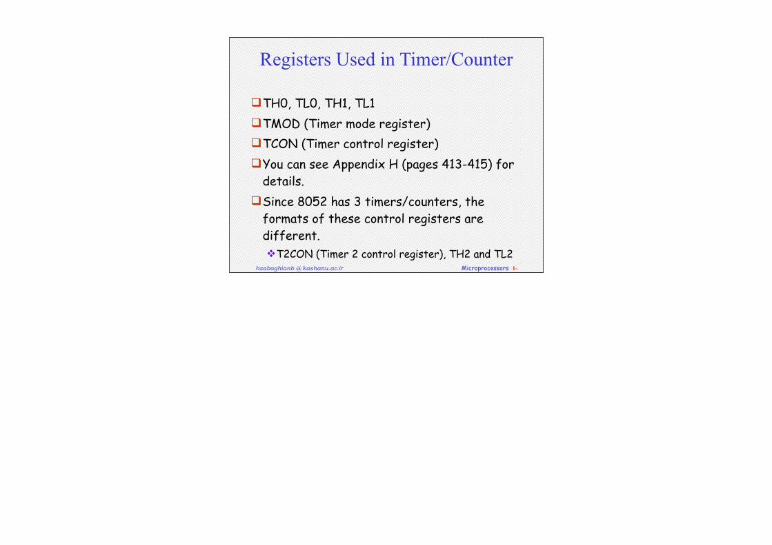
Registers Used in Timer/Counter
TH0, TL0, TH1, TL1 TMOD (Timer mode register)TCON (Timer control register)You can see Appendix H (pages 413-415) for
details.Since 8052 has 3 timers/counters, the
formats of these control registers are different. T2CON (Timer 2 control register), TH2 and TL2
hsabaghianb @ kashanu.ac.ir Microprocessors 1-
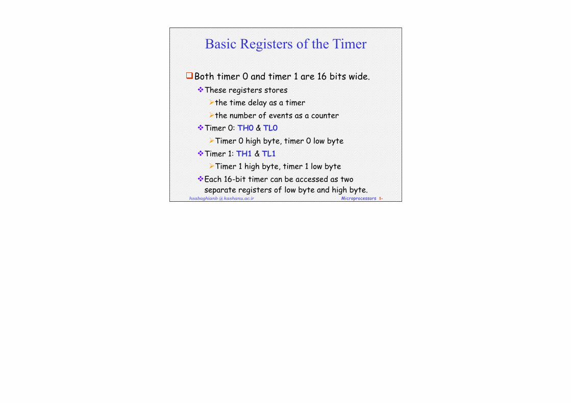
Basic Registers of the Timer
Both timer 0 and timer 1 are 16 bits wide.These registers stores
the time delay as a timerthe number of events as a counter
Timer 0: TH0 & TL0Timer 0 high byte, timer 0 low byte
Timer 1: TH1 & TL1Timer 1 high byte, timer 1 low byte
Each 16-bit timer can be accessed as two separate registers of low byte and high byte.
hsabaghianb @ kashanu.ac.ir Microprocessors 1-
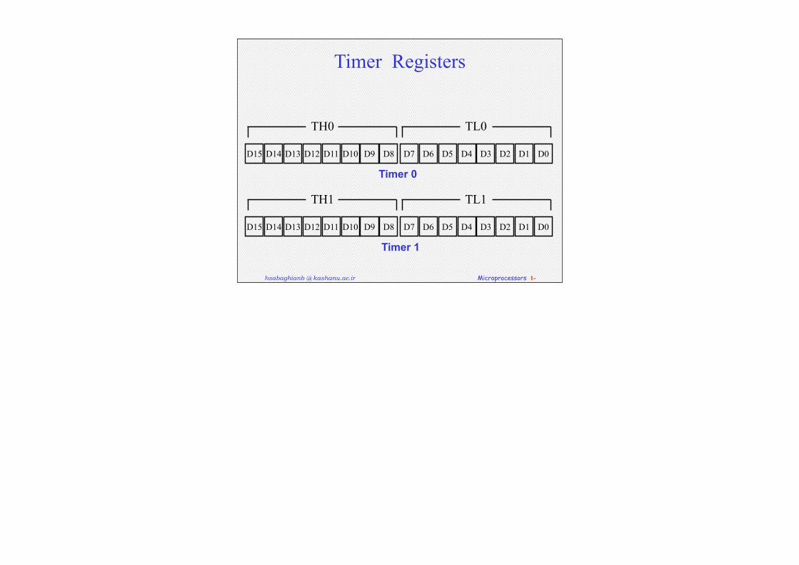
Timer Registers
D15 D8D9D10D11D12D13D14 D7 D0D1D2D3D4D5D6
TH0 TL0
D15 D8D9D10D11D12D13D14 D7 D0D1D2D3D4D5D6
TH1 TL1
Timer 0
Timer 1
hsabaghianb @ kashanu.ac.ir Microprocessors 1-
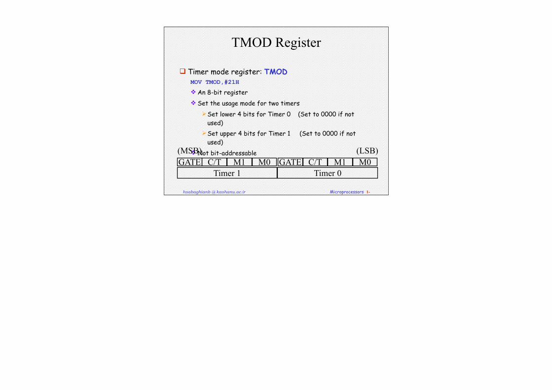
TMOD Register
Timer mode register: TMODMOV TMOD,#21H
An 8-bit register Set the usage mode for two timers
Set lower 4 bits for Timer 0 (Set to 0000 if not used)
Set upper 4 bits for Timer 1 (Set to 0000 if not used)
Not bit-addressable GATE C/T M1 M0 GATE C/T M1 M0
Timer 1 Timer 0
(MSB) (LSB)
hsabaghianb @ kashanu.ac.ir Microprocessors 1-
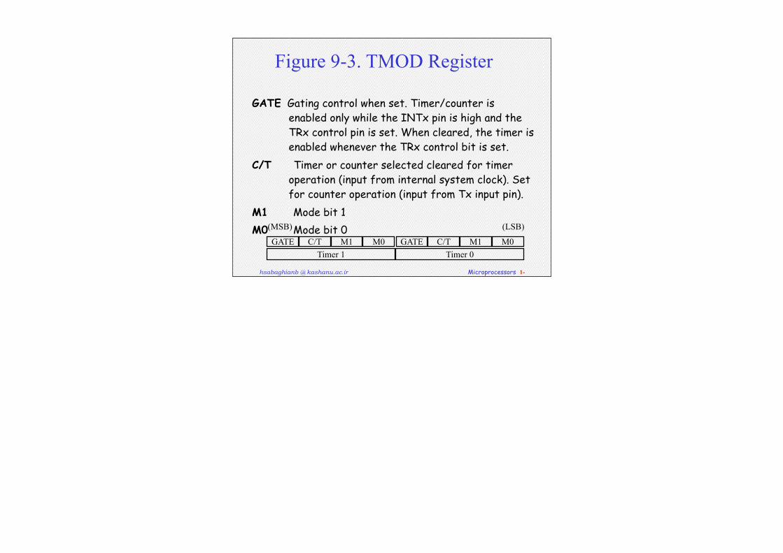
Figure 9-3. TMOD Register
GATE Gating control when set. Timer/counter is enabled only while the INTx pin is high and the TRx control pin is set. When cleared, the timer is enabled whenever the TRx control bit is set.
C/T Timer or counter selected cleared for timer operation (input from internal system clock). Set for counter operation (input from Tx input pin).
M1 Mode bit 1M0 Mode bit 0
GATE C/T M1 M0 GATE C/T M1 M0Timer 1 Timer 0
(MSB) (LSB)
hsabaghianb @ kashanu.ac.ir Microprocessors 1-
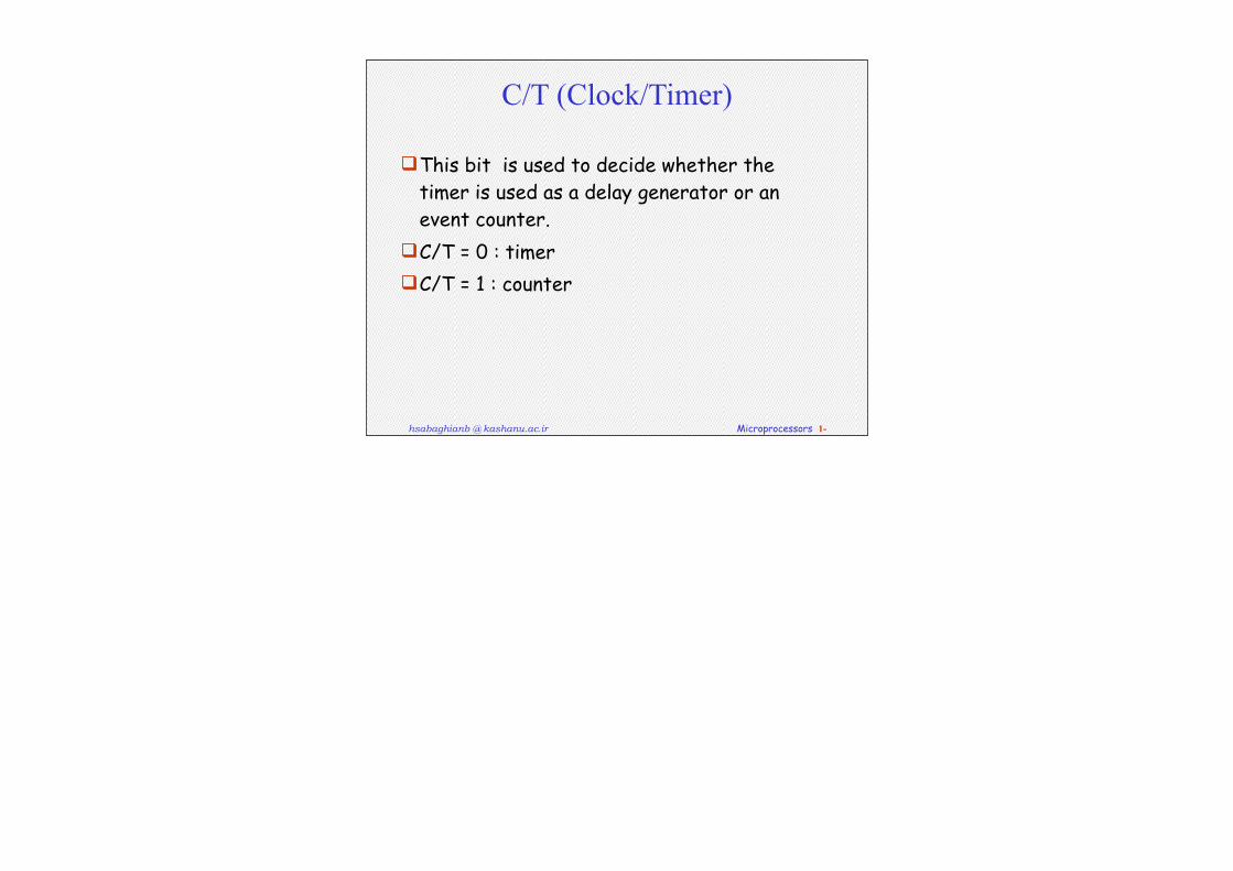
C/T (Clock/Timer)
This bit is used to decide whether the timer is used as a delay generator or an event counter.
C/T = 0 : timerC/T = 1 : counter
hsabaghianb @ kashanu.ac.ir Microprocessors 1-
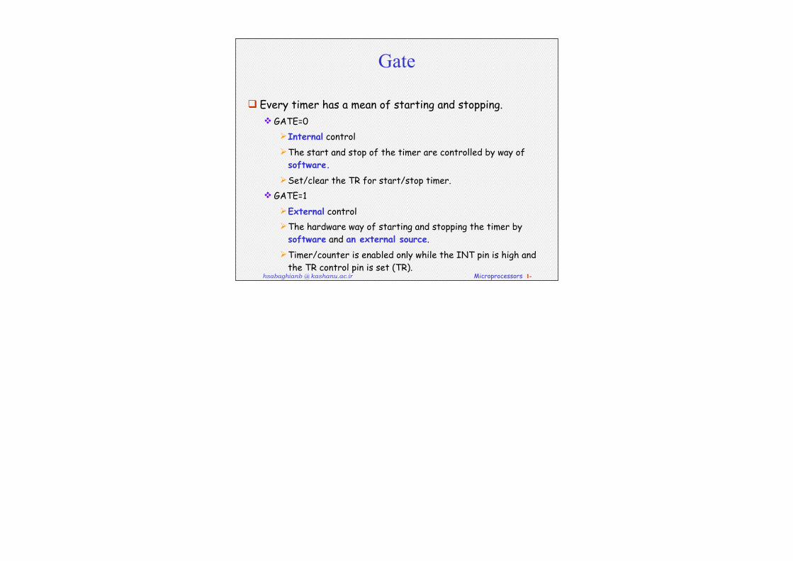
Gate
Every timer has a mean of starting and stopping. GATE=0
Internal controlThe start and stop of the timer are controlled by way of
software.Set/clear the TR for start/stop timer.
GATE=1External controlThe hardware way of starting and stopping the timer by
software and an external source.Timer/counter is enabled only while the INT pin is high and
the TR control pin is set (TR).
hsabaghianb @ kashanu.ac.ir Microprocessors 1-
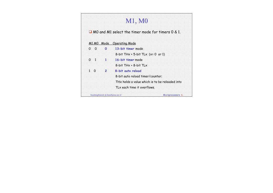
M1, M0 M0 and M1 select the timer mode for timers 0 & 1.
M1 M0 Mode Operating Mode
0 0 0 13-bit timer mode
8-bit THx + 5-bit TLx (x= 0 or 1)
0 1 1 16-bit timer mode
8-bit THx + 8-bit TLx
1 0 2 8-bit auto reload
8-bit auto reload timer/counter;
THx holds a value which is to be reloaded into
TLx each time it overflows.
hsabaghianb @ kashanu.ac.ir Microprocessors 1-
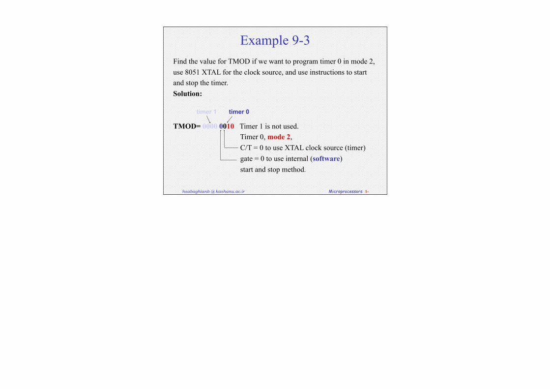
Example 9-3Find the value for TMOD if we want to program timer 0 in mode 2, use 8051 XTAL for the clock source, and use instructions to start and stop the timer.Solution:
TMOD= 0000 0010 Timer 1 is not used. Timer 0, mode 2, C/T = 0 to use XTAL clock source (timer) gate = 0 to use internal (software) start and stop method.
timer 1 timer 0
hsabaghianb @ kashanu.ac.ir Microprocessors 1-
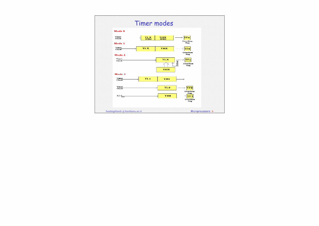
Timer modes
hsabaghianb @ kashanu.ac.ir Microprocessors 1-
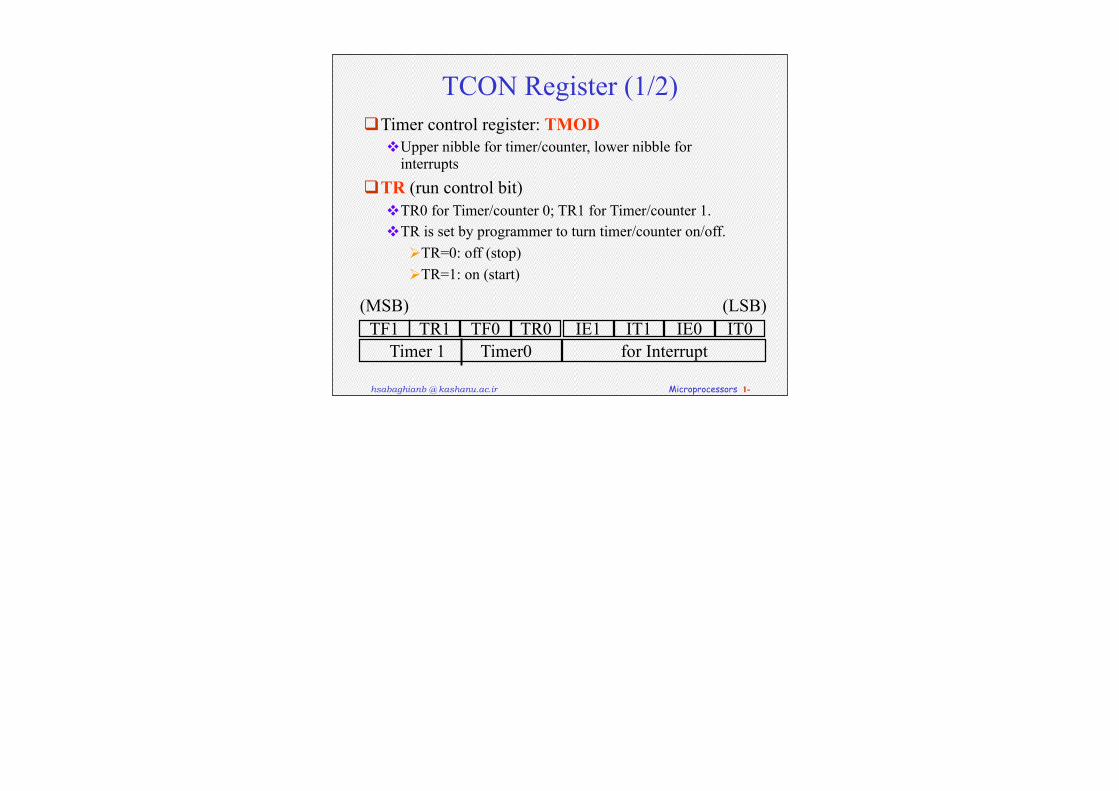
TCON Register (1/2)Timer control register: TMOD
Upper nibble for timer/counter, lower nibble for interrupts
TR (run control bit)TR0 for Timer/counter 0; TR1 for Timer/counter 1.TR is set by programmer to turn timer/counter on/off.
TR=0: off (stop)TR=1: on (start)
TF1 TR1 TF0 TR0 IE1 IT1 IE0 IT0Timer 1 Timer0 for Interrupt
(MSB) (LSB)
hsabaghianb @ kashanu.ac.ir Microprocessors 1-
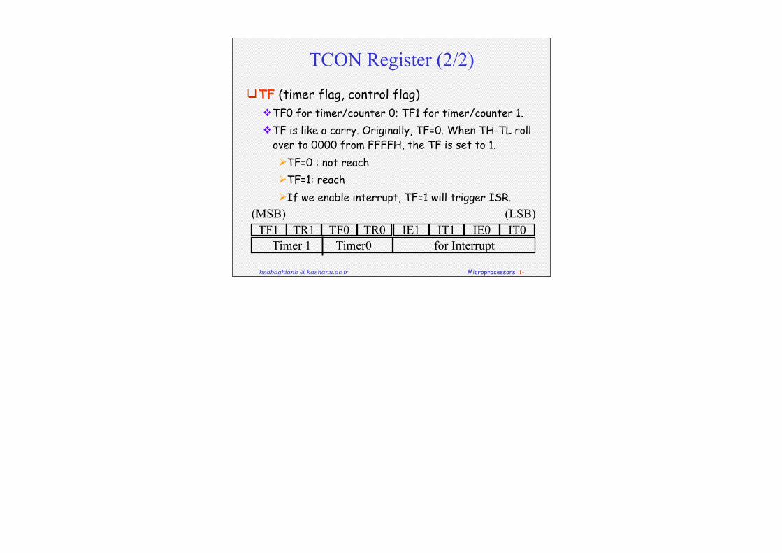
TCON Register (2/2)
TF (timer flag, control flag) TF0 for timer/counter 0; TF1 for timer/counter 1.TF is like a carry. Originally, TF=0. When TH-TL roll
over to 0000 from FFFFH, the TF is set to 1.TF=0 : not reach TF=1: reach If we enable interrupt, TF=1 will trigger ISR.
TF1 TR1 TF0 TR0 IE1 IT1 IE0 IT0Timer 1 Timer0 for Interrupt
(MSB) (LSB)
hsabaghianb @ kashanu.ac.ir Microprocessors 1-
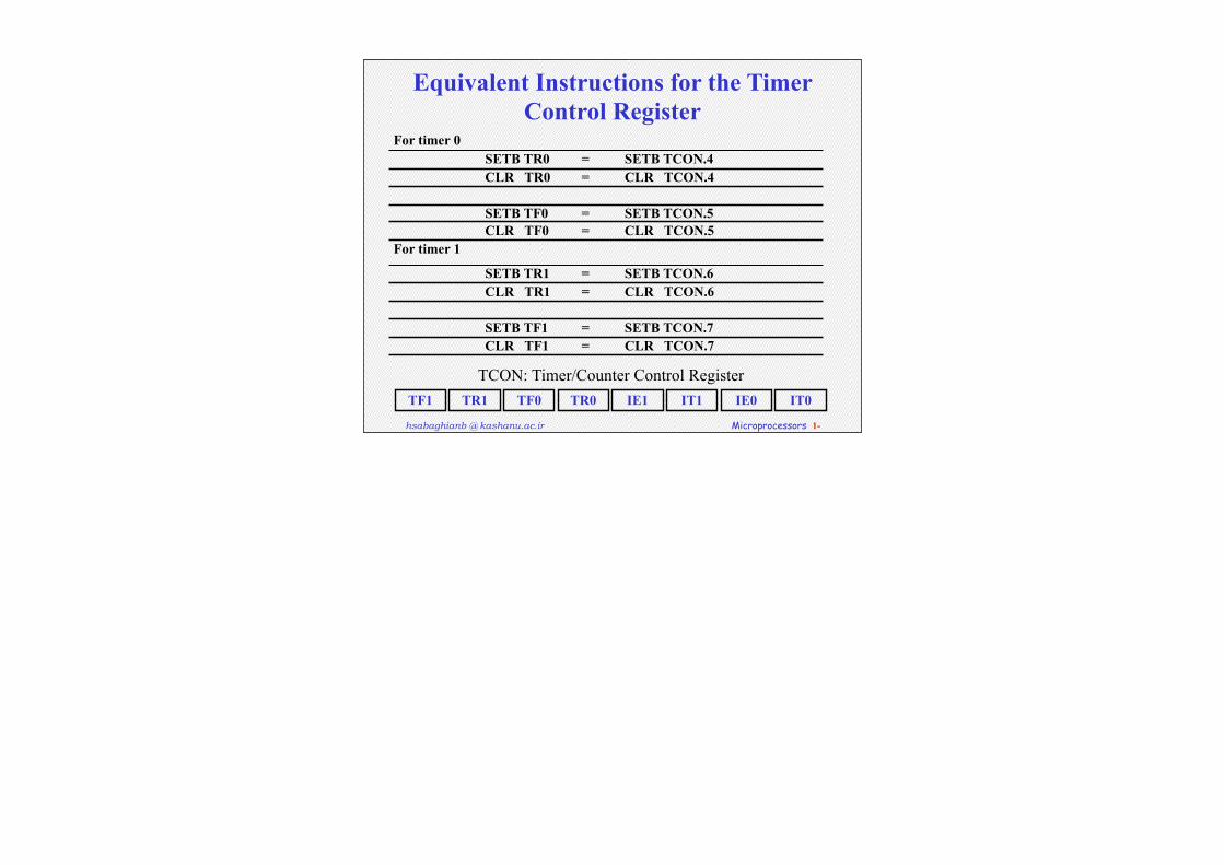
Equivalent Instructions for the Timer Control Register
For timer 0SETB TR0 = SETB TCON.4CLR TR0 = CLR TCON.4
SETB TF0 = SETB TCON.5CLR TF0 = CLR TCON.5
For timer 1
SETB TR1 = SETB TCON.6CLR TR1 = CLR TCON.6
SETB TF1 = SETB TCON.7CLR TF1 = CLR TCON.7
TF1 IT0IE0IT1IE1TR0TF0TR1
TCON: Timer/Counter Control Register
hsabaghianb @ kashanu.ac.ir Microprocessors 1-
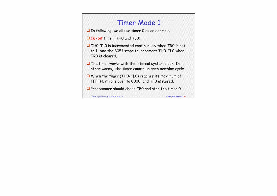
Timer Mode 1 In following, we all use timer 0 as an example.
16-bit timer (TH0 and TL0)
TH0-TL0 is incremented continuously when TR0 is set to 1. And the 8051 stops to increment TH0-TL0 when TR0 is cleared.
The timer works with the internal system clock. In other words, the timer counts up each machine cycle.
When the timer (TH0-TL0) reaches its maximum of FFFFH, it rolls over to 0000, and TF0 is raised.
Programmer should check TF0 and stop the timer 0.

hsabaghianb @ kashanu.ac.ir Microprocessors 1-
Steps of Mode 1 (1/3)
1. Choose mode 1 timer 0 MOV TMOD,#01H
2. Set the original value to TH0 and TL0. MOV TH0,#FFH MOV TL0,#FCH
3. You had better to clear the flag to monitor: TF0=0. CLR TF0
4. Start the timer. SETB TR0
hsabaghianb @ kashanu.ac.ir Microprocessors 1-
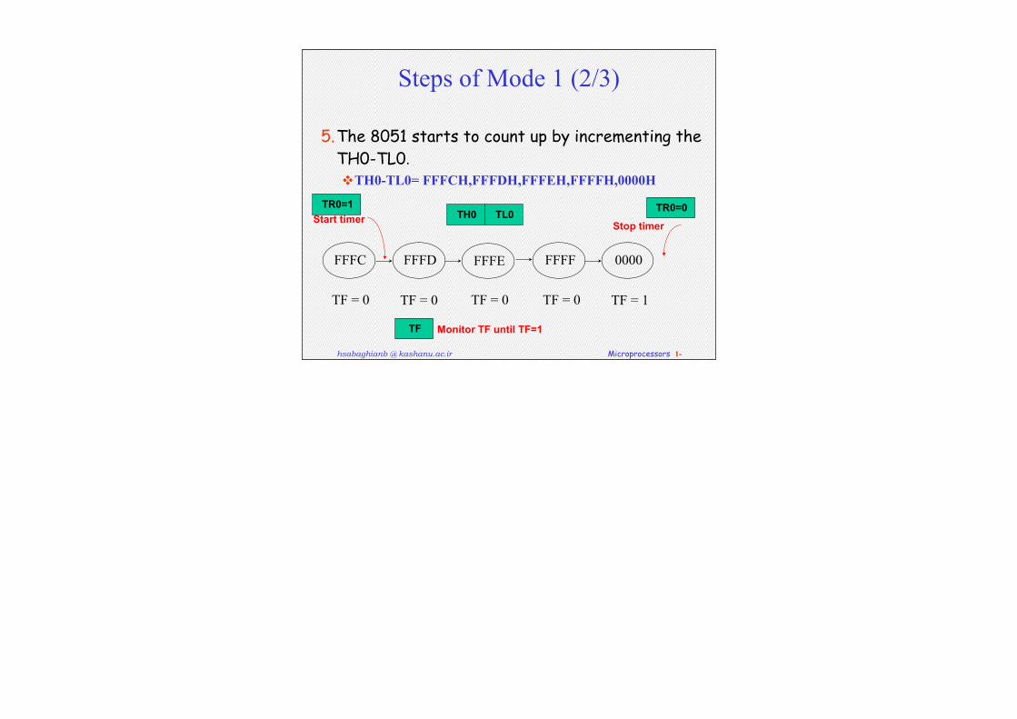
Steps of Mode 1 (2/3)
5.The 8051 starts to count up by incrementing the TH0-TL0.TH0-TL0= FFFCH,FFFDH,FFFEH,FFFFH,0000H
FFFC FFFD FFFE FFFF 0000
TF = 0 TF = 0 TF = 0 TF = 0 TF = 1
TH0 TL0Start timer Stop timer
Monitor TF until TF=1
TR0=1 TR0=0
TF
hsabaghianb @ kashanu.ac.ir Microprocessors 1-
Steps of Mode 1 (3/3)
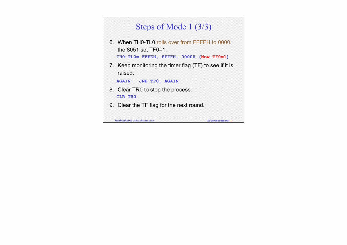
6. WhenTH0-TL0rollsoverfromFFFFHto0000,the8051setTF0=1.TH0-TL0= FFFEH, FFFFH, 0000H (Now TF0=1)
7. Keepmonitoringthetimerflag(TF)toseeifitisraised.AGAIN: JNB TF0, AGAIN
8. ClearTR0tostoptheprocess.CLR TR0
9. CleartheTFflagforthenextround.
hsabaghianb @ kashanu.ac.ir Microprocessors 1-
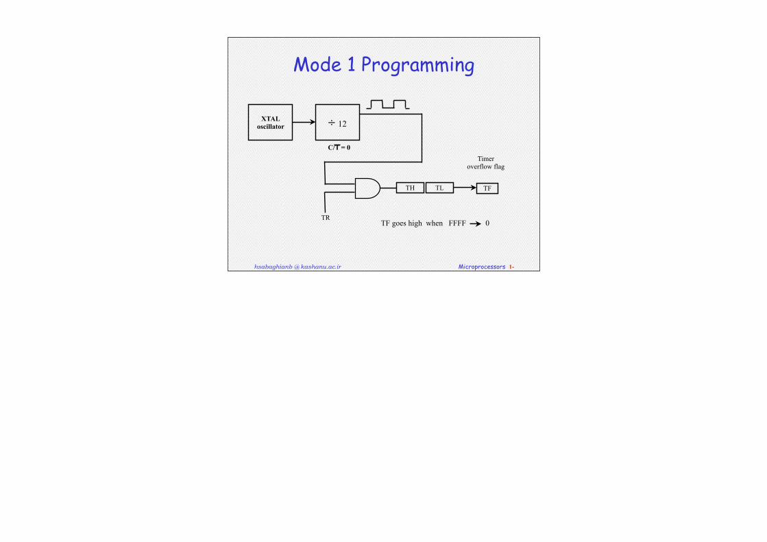
Mode 1 Programming
XTALoscillator ÷ 12
TR
TH TL TF
Timeroverflow flag
C/T = 0
TF goes high when FFFF 0
hsabaghianb @ kashanu.ac.ir Microprocessors 1-
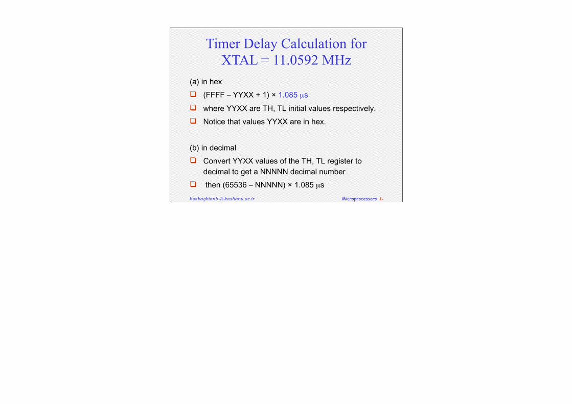
Timer Delay Calculation for XTAL = 11.0592 MHz
(a)inhex (FFFF–YYXX+1)×1.085µs whereYYXXareTH,TLinitialvaluesrespectively. NoticethatvaluesYYXXareinhex.
(b)indecimal ConvertYYXXvaluesoftheTH,TLregistertodecimaltogetaNNNNNdecimalnumber
then(65536–NNNNN)×1.085µs
hsabaghianb @ kashanu.ac.ir Microprocessors 1-
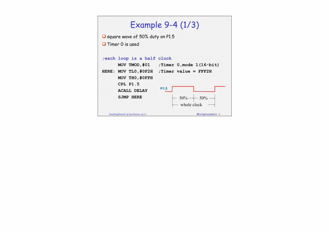
Example 9-4 (1/3) square wave of 50% duty on P1.5 Timer 0 is used
;each loop is a half clock MOV TMOD,#01 ;Timer 0,mode 1(16-bit)HERE: MOV TL0,#0F2H ;Timer value = FFF2H MOV TH0,#0FFH CPL P1.5 ACALL DELAY SJMP HERE 50% 50%
whole clock
P1.5
hsabaghianb @ kashanu.ac.ir Microprocessors 1-
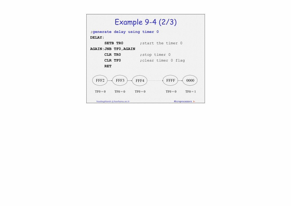
Example 9-4 (2/3);generate delay using timer 0DELAY: SETB TR0 ;start the timer 0AGAIN:JNB TF0,AGAIN CLR TR0 ;stop timer 0 CLR TF0 ;clear timer 0 flag RET
FFF2 FFF3 FFF4 FFFF 0000
TF0 = 0 TF0 = 0 TF0 = 0 TF0 = 0 TF0 = 1
hsabaghianb @ kashanu.ac.ir Microprocessors 1-
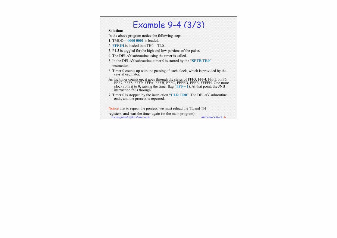
Example 9-4 (3/3)Solution:In the above program notice the following steps.1. TMOD = 0000 0001 is loaded.2. FFF2H is loaded into TH0 – TL0.3. P1.5 is toggled for the high and low portions of the pulse.4. The DELAY subroutine using the timer is called.5. In the DELAY subroutine, timer 0 is started by the “SETB TR0” instruction.6. Timer 0 counts up with the passing of each clock, which is provided by the
crystal oscillator. As the timer counts up, it goes through the states of FFF3, FFF4, FFF5, FFF6,
FFF7, FFF8, FFF9, FFFA, FFFB, FFFC, FFFFD, FFFE, FFFFH. One more clock rolls it to 0, raising the timer flag (TF0 = 1). At that point, the JNB instruction falls through.
7. Timer 0 is stopped by the instruction “CLR TR0”. The DELAY subroutine ends, and the process is repeated.
Notice that to repeat the process, we must reload the TL and TH registers, and start the timer again (in the main program).
hsabaghianb @ kashanu.ac.ir Microprocessors 1-
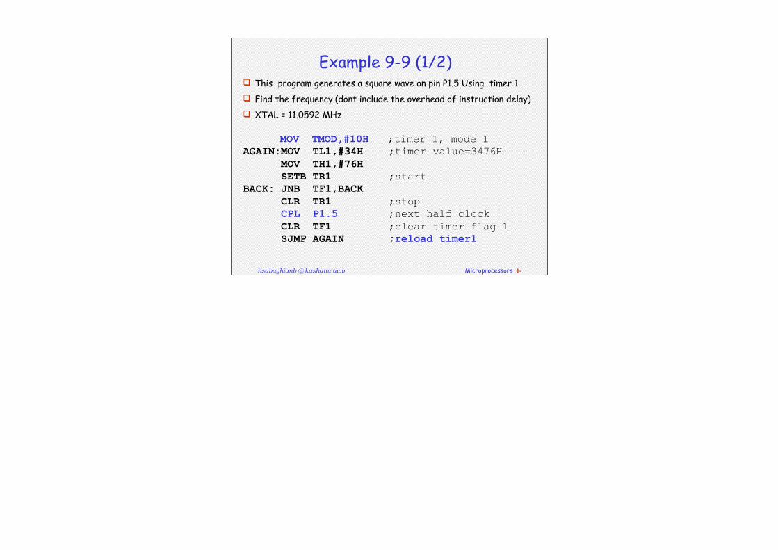
Example 9-9 (1/2) This program generates a square wave on pin P1.5 Using timer 1 Find the frequency.(dont include the overhead of instruction delay) XTAL = 11.0592 MHz MOV TMOD,#10H ;timer 1, mode 1AGAIN:MOV TL1,#34H ;timer value=3476H MOV TH1,#76H SETB TR1 ;startBACK: JNB TF1,BACK CLR TR1 ;stop CPL P1.5 ;next half clock CLR TF1 ;clear timer flag 1 SJMP AGAIN ;reload timer1
hsabaghianb @ kashanu.ac.ir Microprocessors 1-
Example 9-9 (2/2)
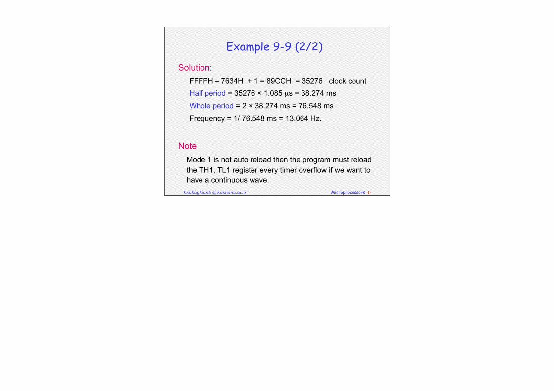
Solution:FFFFH–7634H+1=89CCH=35276clockcountHalfperiod=35276×1.085µs=38.274msWholeperiod=2×38.274ms=76.548msFrequency=1/76.548ms=13.064Hz.
NoteMode1isnotautoreloadthentheprogrammustreloadtheTH1,TL1registereverytimeroverflowifwewanttohaveacontinuouswave.
hsabaghianb @ kashanu.ac.ir Microprocessors 1-
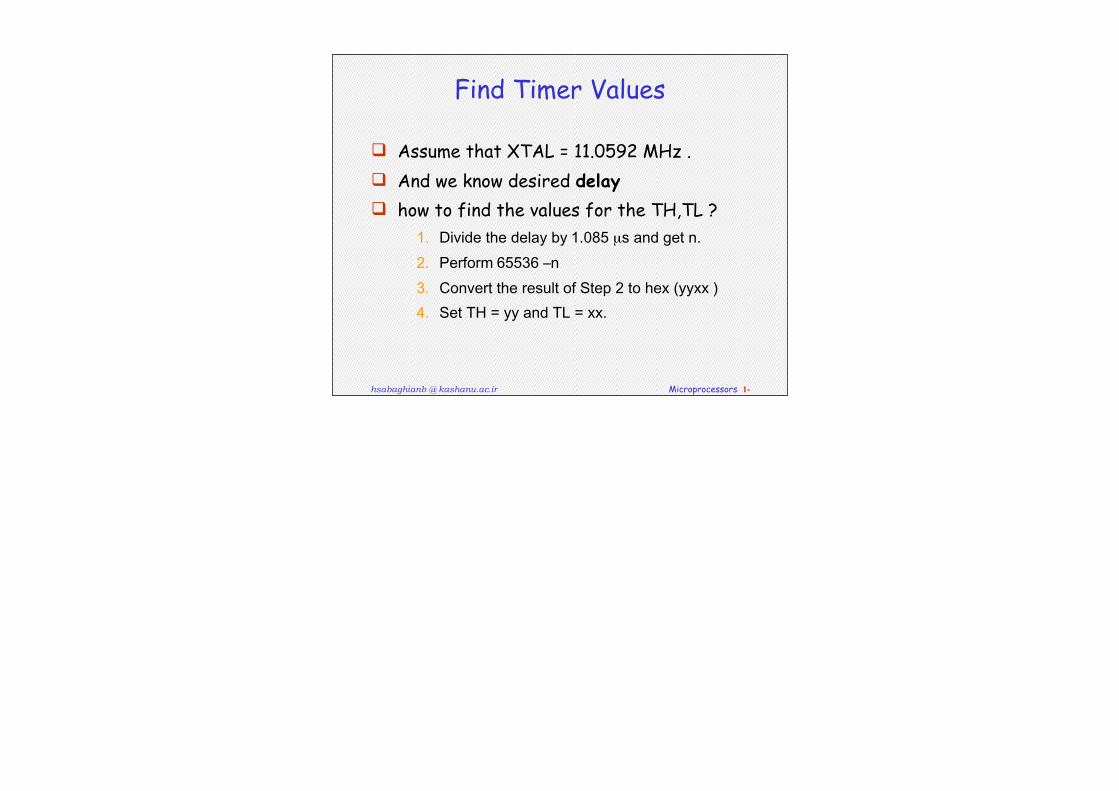
Find Timer Values
Assume that XTAL = 11.0592 MHz . And we know desired delay how to find the values for the TH,TL ?
1. Dividethedelayby1.085µsandgetn.2. Perform65536–n3. ConverttheresultofStep2tohex(yyxx)4. SetTH=yyandTL=xx.
hsabaghianb @ kashanu.ac.ir Microprocessors 1-
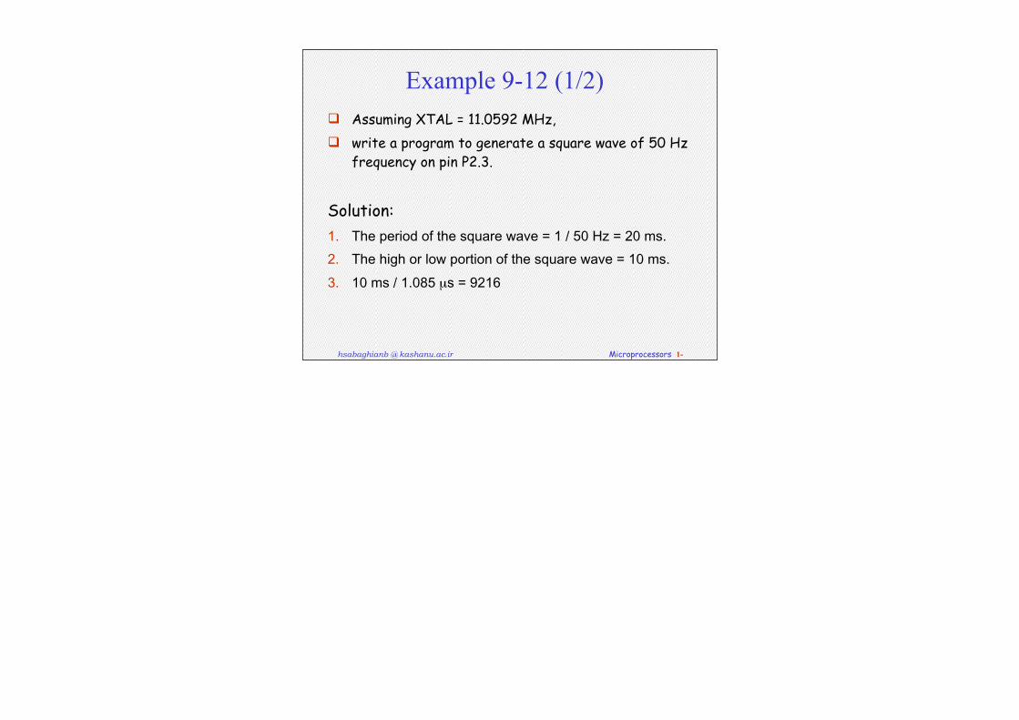
Example 9-12 (1/2) Assuming XTAL = 11.0592 MHz, write a program to generate a square wave of 50 Hz
frequency on pin P2.3.
Solution:1. Theperiodofthesquarewave=1/50Hz=20ms.2. Thehighorlowportionofthesquarewave=10ms.3. 10ms/1.085µs=9216
hsabaghianb @ kashanu.ac.ir Microprocessors 1-
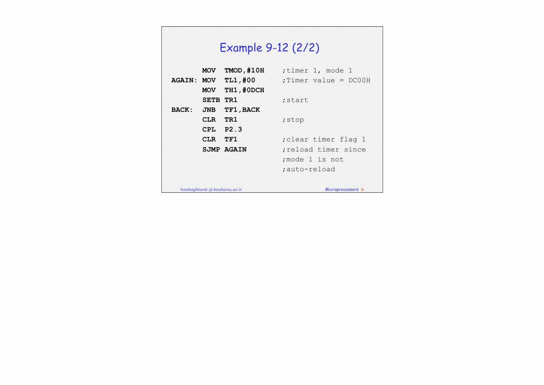
Example 9-12 (2/2)
MOV TMOD,#10H ;timer 1, mode 1AGAIN: MOV TL1,#00 ;Timer value = DC00H MOV TH1,#0DCH SETB TR1 ;startBACK: JNB TF1,BACK CLR TR1 ;stop CPL P2.3 CLR TF1 ;clear timer flag 1 SJMP AGAIN ;reload timer since ;mode 1 is not ;auto-reload
hsabaghianb @ kashanu.ac.ir Microprocessors 1-
Generate a Large Time Delay
The size of the time delay depends on two factors:They crystal frequencyThe timer’s 16-bit register, TH & TL
The largest time delay is achieved by making TH=TL=0. What if that is not enough? Next Example show how to achieve large time delay
hsabaghianb @ kashanu.ac.ir Microprocessors 1-
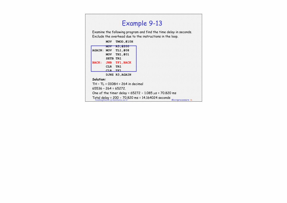
Example 9-13Examine the following program and find the time delay in seconds. Exclude the overhead due to the instructions in the loop. MOV TMOD,#10H MOV R3,#200 AGAIN: MOV TL1,#08 MOV TH1,#01 SETB TR1 BACK: JNB TF1,BACK CLR TR1 CLR TF1 DJNZ R3,AGAIN Solution:TH – TL = 0108H = 264 in decimal 65536 – 264 = 65272.One of the timer delay = 65272 × 1.085 µs = 70.820 msTotal delay = 200 × 70.820 ms = 14.164024 seconds
hsabaghianb @ kashanu.ac.ir Microprocessors 1-
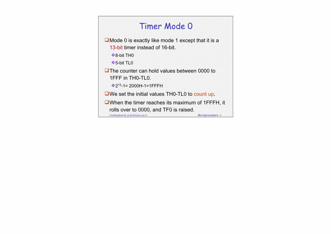
Timer Mode 0Mode0isexactlylikemode1exceptthatitisa13-bittimerinsteadof16-bit.8-bitTH05-bitTL0
Thecountercanholdvaluesbetween0000to1FFFinTH0-TL0.213-1=2000H-1=1FFFH
WesettheinitialvaluesTH0-TL0tocountup.Whenthetimerreachesitsmaximumof1FFFH,itrollsoverto0000,andTF0israised.
hsabaghianb @ kashanu.ac.ir Microprocessors 1-
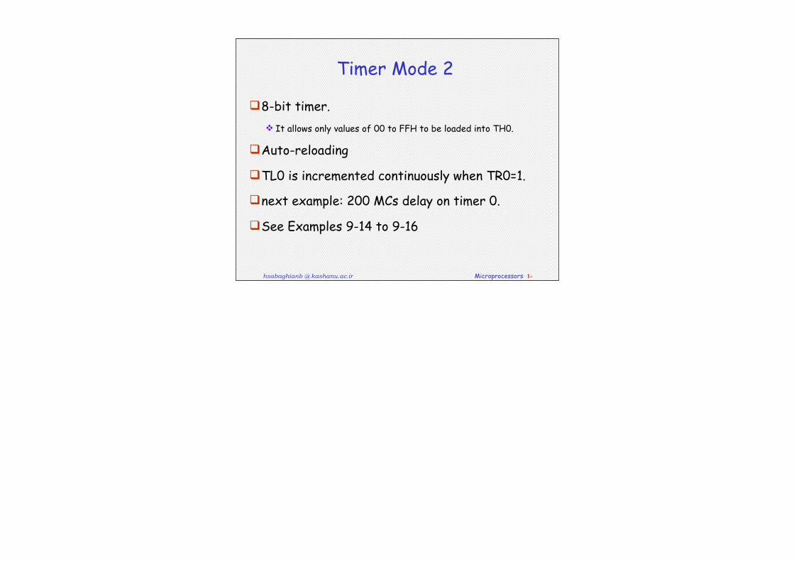
Timer Mode 2
8-bit timer. It allows only values of 00 to FFH to be loaded into TH0.
Auto-reloading
TL0 is incremented continuously when TR0=1.
next example: 200 MCs delay on timer 0.
See Examples 9-14 to 9-16
hsabaghianb @ kashanu.ac.ir Microprocessors 1-
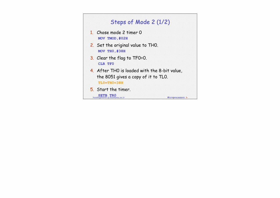
Steps of Mode 2 (1/2)
1. Chose mode 2 timer 0 MOV TMOD,#02H
2. Set the original value to TH0. MOV TH0,#38H
3. Clear the flag to TF0=0. CLR TF0
4. After TH0 is loaded with the 8-bit value, the 8051 gives a copy of it to TL0. TL0=TH0=38H
5. Start the timer. SETB TR0

hsabaghianb @ kashanu.ac.ir Microprocessors 1-
Steps of Mode 2 (2/2)
6. The 8051 starts to count up by incrementing the TL0. TL0= 38H, 39H, 3AH,....
7. When TL0 rolls over from FFH to 00, the 8051 set TF0=1. Also, TL0 is reloaded automatically with the value kept by the TH0. TL0= FEH, FFH, 00H (Now TF0=1)
The 8051 auto reload TL0=TH0=38H. Clr TF0
Go to Step 6 (i.e., TL0 is incrementing continuously).
Note that we must clear TF0 when TL0 rolls over. Thus, we can monitor TF0 in next process.
Clear TR0 to stop the process.
hsabaghianb @ kashanu.ac.ir Microprocessors 1-
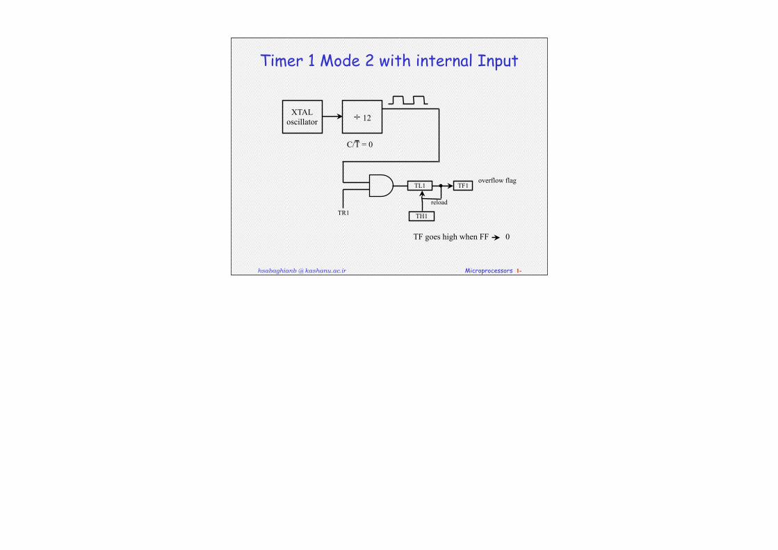
Timer 1 Mode 2 with internal Input
XTALoscillator ÷ 12
TR1
TL1
TH1
TF1overflow flag
reload
TF goes high when FF 0
C/T = 0
hsabaghianb @ kashanu.ac.ir Microprocessors 1-
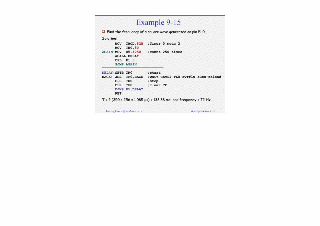
Example 9-15 Find the frequency of a square wave generated on pin P1.0.
Solution: MOV TMOD,#2H ;Timer 0,mode 2 MOV TH0,#0 AGAIN:MOV R5,#250 ;count 250 times ACALL DELAY CPL P1.0 SJMP AGAIN
DELAY:SETB TR0 ;startBACK: JNB TF0,BACK ;wait until TL0 ovrflw auto-reload CLR TR0 ;stop CLR TF0 ;clear TF DJNZ R5,DELAY RET
T = 2 (250 × 256 × 1.085 µs) = 138.88 ms, and frequency = 72 Hz.
hsabaghianb @ kashanu.ac.ir Microprocessors 1-
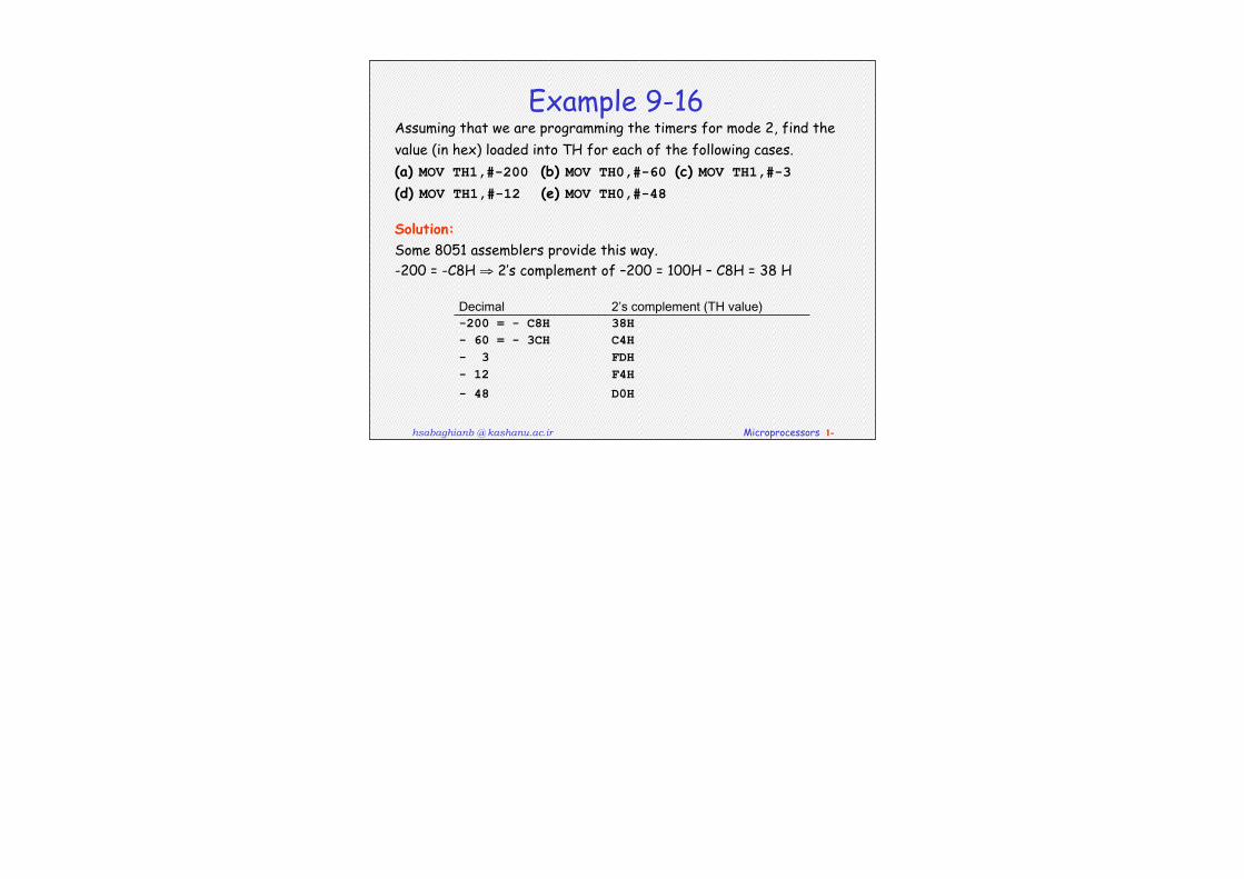
Example 9-16Assuming that we are programming the timers for mode 2, find the value (in hex) loaded into TH for each of the following cases.(a) MOV TH1,#-200 (b) MOV TH0,#-60 (c) MOV TH1,#-3(d) MOV TH1,#-12 (e) MOV TH0,#-48
Solution:Some 8051 assemblers provide this way.-200 = -C8H ⇒ 2’s complement of –200 = 100H – C8H = 38 H
Decimal 2’scomplement(THvalue)-200 = - C8H 38H- 60 = - 3CH C4H- 3 FDH- 12 F4H
- 48 D0H
hsabaghianb @ kashanu.ac.ir Microprocessors 1-
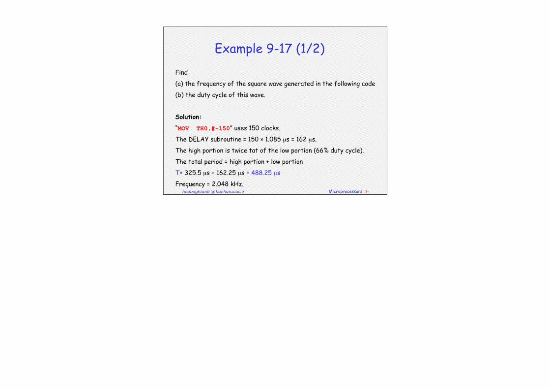
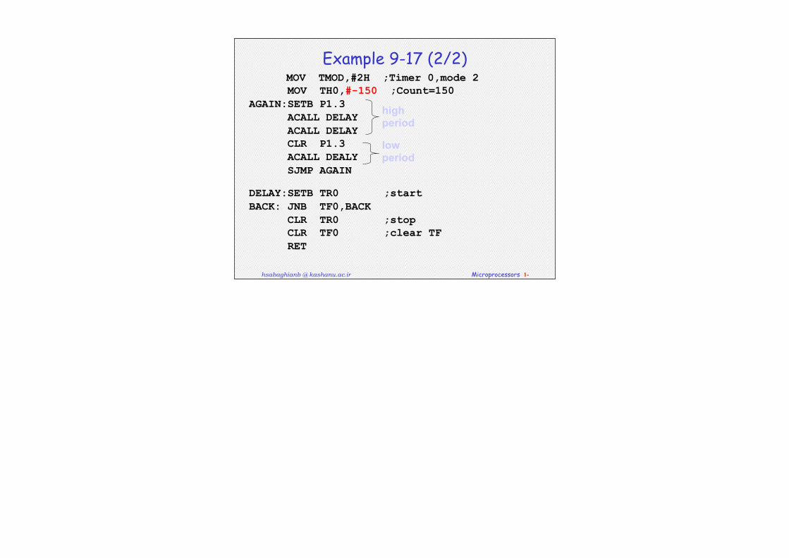
Example 9-17 (1/2)
Find
(a) the frequency of the square wave generated in the following code
(b) the duty cycle of this wave.
Solution:
“MOV TH0,#-150” uses 150 clocks.
The DELAY subroutine = 150 × 1.085 µs = 162 µs.
The high portion is twice tat of the low portion (66% duty cycle).
The total period = high portion + low portion
T= 325.5 µs + 162.25 µs = 488.25 µs
Frequency = 2.048 kHz.
hsabaghianb @ kashanu.ac.ir Microprocessors 1-
Example 9-17 (2/2) MOV TMOD,#2H ;Timer 0,mode 2 MOV TH0,#-150 ;Count=150AGAIN:SETB P1.3 ACALL DELAY ACALL DELAY CLR P1.3 ACALL DEALY SJMP AGAIN
DELAY:SETB TR0 ;startBACK: JNB TF0,BACK CLR TR0 ;stop CLR TF0 ;clear TF RET
high period
low period