Embed Size (px)
Citation preview
GEN.0000000004927 Rev B © 2016 SRAM, LLC
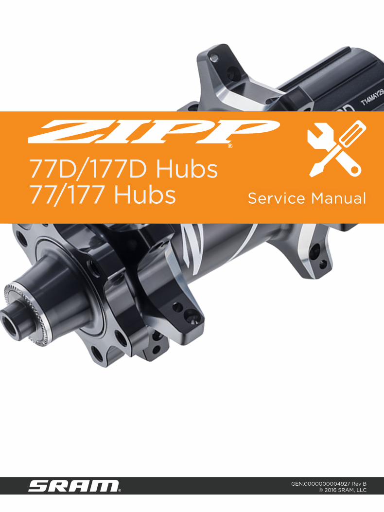
Service Manual
77D/177D Hubs77/177 Hubs
SRAM LLC WARRANTYEXTENT OF LIMITED WARRANTYExcept as otherwise set forth herein, SRAM warrants its products to be free from defects in materials or workmanship for a period of two years after original purchase. This warranty only applies to the original owner and is not transferable. Claims under this warranty must be made through the retailer where the bicycle or the SRAM component was purchased. Original proof of purchase is required. Except as described herein, SRAM makes no other warranties, guaranties, or representations of any type (express or implied), and all warranties (including any implied warranties of reasonable care, merchantibility, or fitness for a particular purpose) are hereby disclaimed.
LOCAL LAWThis warranty statement gives the customer specific legal rights. The customer may also have other rights which vary from state to state (USA), from province to province (Canada), and from country to country elsewhere in the world.
To the extent that this warranty statement is inconsistent with the local law, this warranty shall be deemed modified to be consistent with such law, under such local law, certain disclaimers and limitations of this warranty statement may apply to the customer. For example, some states in the United States of America, as well as some governments outside of the United States (including provinces in Canada) may:
a. Preclude the disclaimers and limitations of this warranty statement from limiting the statutory rights of the consumer (e.g. United Kingdom).
b. Otherwise restrict the ability of a manufacturer to enforce such disclaimers or limitations.
For Australian customers:This SRAM limited warranty is provided in Australia by SRAM LLC, 1000 W. Fulton Market, 4th Floor, Chicago, IL, 60607, USA. To make a warranty claim please contact the retailer from whom you purchased this SRAM product. Alternatively, you may make a claim by contacting SRAM Australia, 6 Marco Court, Rowville 3178, Australia. For valid claims SRAM will, at its option, either repair or replace your SRAM product. Any expenses incurred in making the warranty claim are your responsibility. The benefits given by this warranty are additional to other rights and remedies that you may have under laws relating to our products. Our goods come with guarantees that cannot be excluded under the Australian Consumer Law. You are entitled to a replacement or refund for a major failure and for compensation for any other reasonably foreseeable loss or damage. You are also entitled to have the goods repaired or replaced if the goods fail to be of acceptable quality and the failure does not amount to a major failure.
LIMITATIONS OF LIABILITYTo the extent allowed by local law, except for the obligations specifically set forth in this warranty statement, in no event shall SRAM or its third party suppliers be liable for direct, indirect, special, incidental, or consequential damages.
LIMITATIONS OF WARRANTYThis warranty does not apply to products that have been incorrectly installed and/or adjusted according to the respective SRAM user manual. The SRAM user manuals can be found online at sram.com, rockshox.com, avidbike.com, truvativ.com, or zipp.com.
This warranty does not apply to damage to the product caused by a crash, impact, abuse of the product, non-compliance with manufacturers specifications of usage or any other circumstances in which the product has been subjected to forces or loads beyond its design.
This warranty does not apply when the product has been modified, including, but not limited to any attempt to open or repair any electronic and electronic related components, including the motor, controller, battery packs, wiring harnesses, switches, and chargers.
This warranty does not apply when the serial number or production code has been deliberately altered, defaced or removed.
This warranty does not apply to normal wear and tear. Wear and tear parts are subject to damage as a result of normal use, failure to service according to SRAM recommendations and/or riding or installation in conditions or applications other than recommended.
Wear and tear parts are identified as:
• Dust seals• Bushings• Air sealing o-rings• Glide rings• Rubber moving parts• Foam rings• Rear shock mounting hardware
and main seals• Upper tubes (stanchions)
• Stripped threads/bolts (aluminium, titanium, magnesium or steel)
• Brake sleeves• Brake pads• Chains• Sprockets• Cassettes• Shifter and brake cables (inner
and outer)
• Handlebar grips• Shifter grips• Jockey wheels• Disc brake rotors• Wheel braking surfaces• Bottomout pads• Bearings• Bearing races• Pawls
• Transmission gears• Spokes• Free hubs• Aero bar pads• Corrosion• Tools• Motors• Batteries
Notwithstanding anything else set forth herein, the battery pack and charger warranty does not include damage from power surges, use of improper charger, improper maintenance, or such other misuse.
This warranty shall not cover damages caused by the use of parts of different manufacturers.
This warranty shall not cover damages caused by the use of parts that are not compatible, suitable and/or authorised by SRAM for use with SRAM components.
This warranty shall not cover damages resulting from commercial (rental) use.
TABLE OF CONTENTSREAR HUB SERVICE ................................................................................................................................................................... 5
TOOLS NEEDED FOR SERVICE ............................................................................................................................................................................................. 5REPLACEMENT PARTS ............................................................................................................................................................................................................. 5REAR HUB EXPLODED VIEW - 177D .................................................................................................................................................................................. 6REAR HUB END CAPS - 177D ................................................................................................................................................................................................. 6REAR HUB EXPLODED VIEW - 177 ...................................................................................................................................................................................... 7REAR HUB END CAPS - 177 .................................................................................................................................................................................................... 7REAR HUB BEARING REMOVAL .......................................................................................................................................................................................... 8REAR HUB BEARING INSTALLATION .............................................................................................................................................................................. 10DRIVER BODY INSTALLATION .............................................................................................................................................................................................12END CAP INSTALLATION .......................................................................................................................................................................................................13
FRONT HUB SERVICE .............................................................................................................................................................. 14TOOLS NEEDED FOR SERVICE ............................................................................................................................................................................................14REPLACEMENT PARTS ............................................................................................................................................................................................................14FRONT HUB EXPLODED VIEW - 77D ................................................................................................................................................................................15FRONT HUB END CAPS - 77D...............................................................................................................................................................................................15FRONT HUB EXPLODED VIEW - 77 ...................................................................................................................................................................................16FRONT HUB END CAPS - 77 ..................................................................................................................................................................................................16FRONT HUB BEARING REMOVAL ...................................................................................................................................................................................... 17FRONT HUB BEARING INSTALLATION ............................................................................................................................................................................19END CAP INSTALLATION ......................................................................................................................................................................................................22

SAFETY FIRST!We care about YOU. Please, always wear your safety glasses and
protective gloves when servicing Zipp® products. Protect yourself! Wear your safety gear!
5Rear Hub Service
R e a r H u b S e r v i c eThe hub can be serviced while in the wheel. However, if your spokes or rim are damaged, you can remove the hub from the wheel which will make servicing your hub easier. To remove the hub, use a spoke wrench to de-tension the spokes, then use a pair of metal snips to cut the spokes, remove the hub from the wheel, and remove the spoke ends from the hub (not pictured).
T o o l s N e e d e d f o r S e r v i c e
• Safety glasses• Clean, lint-free rags• Nitrile gloves• Isopropyl alcohol• Bench vise• Aluminum vise blocks• Plastic mallet• SRAM® Butter grease• Grease brush• Cable tie or flat blade screwdriver
• Sealed bearing puller with 17 mm slotted attachment• Sealed bearing press• (2) 6903 bearing press adapters• (1) 17 mm (ID) over axle bearing spacer (min length of 50 mm)• (2) 17 mm (ID) over axle bearing spacers (min length of 9 mm)
R e p l a c e m e n t P a r t s
• (2) Zipp® 61903 177D/177 hub bearings• Zipp 177D/177 driver body kit (optional)• Zipp 177D/177 driver body seal and shim kit
For part numbers, please refer to the Zipp Spare Parts Catalog in the Support section of www.zipp.com.
SA F E T Y I N S T R U C TI O N SAlways wear nitrile gloves when working with bicycle grease.

6Rear Hub Exploded View - 177D
R e a r H u b E x p l o d e d V i e w - 1 7 7 D
R e a r H u b E n d C a p s - 1 7 7 D
Quick Release 12 mm x 142 mm 12 mm x 135 mm
Dri
ve S
ide
No
n-D
rive
Sid
e
Driver Body Driver Body Seal
Disc Brake Hub ShellShim
61903 Bearing
61903 BearingAxle
7Rear Hub Exploded View - 177
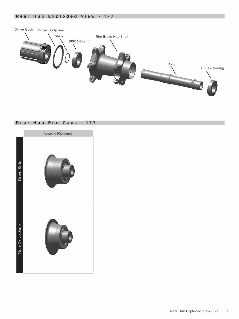
R e a r H u b E x p l o d e d V i e w - 1 7 7
R e a r H u b E n d C a p s - 1 7 7
Quick Release
Dri
ve S
ide
No
n-D
rive
Sid
e
Driver Body Driver Body Seal
Rim Brake Hub ShellShim
61903 Bearing
61903 BearingAxle

8Rear Hub Bearing Removal
R e a r H u b B e a r i n g R e m o v a l
Rear hub bearing removal procedures are the same for disc brake 177D and rim brake 177 hubs. The 177D disc brake hub is pictured.
NOTICETo prevent damage to the hub surfaces, do not use Acetone or similar products to clean parts.
Clamp the aluminum vise blocks into a vise. Clamp the small diameter of the end cap into the vise blocks and pull up on the hub to remove the end cap. Repeat on the other side to remove the other end cap.
Alternate method: To remove quick release end caps, insert a quick release skewer into one side of the hub and use the skewer to push the opposite end cap off the hub. Repeat to remove the other end cap.
Position the wheel horizontally with the driver body facing downward. This will allow the pawls and leaf springs to remain in the driver body as it is being removed. Use your fingers to remove the driver body assembly from the hub shell.
NOTICEA shim rests on the bearing located on the inboard side of the driver body. If this shim falls off when you remove the axle, set it aside until you are ready for assembly.
Use a plastic mallet to gently tap the exposed axle end on the non-drive side of the hub to dislodge the drive side bearing.
Remove the axle and drive side bearing from the hub shell.
1
Aluminum vise blocks
2
Plastic mallet
3
9Rear Hub End Caps - 177D
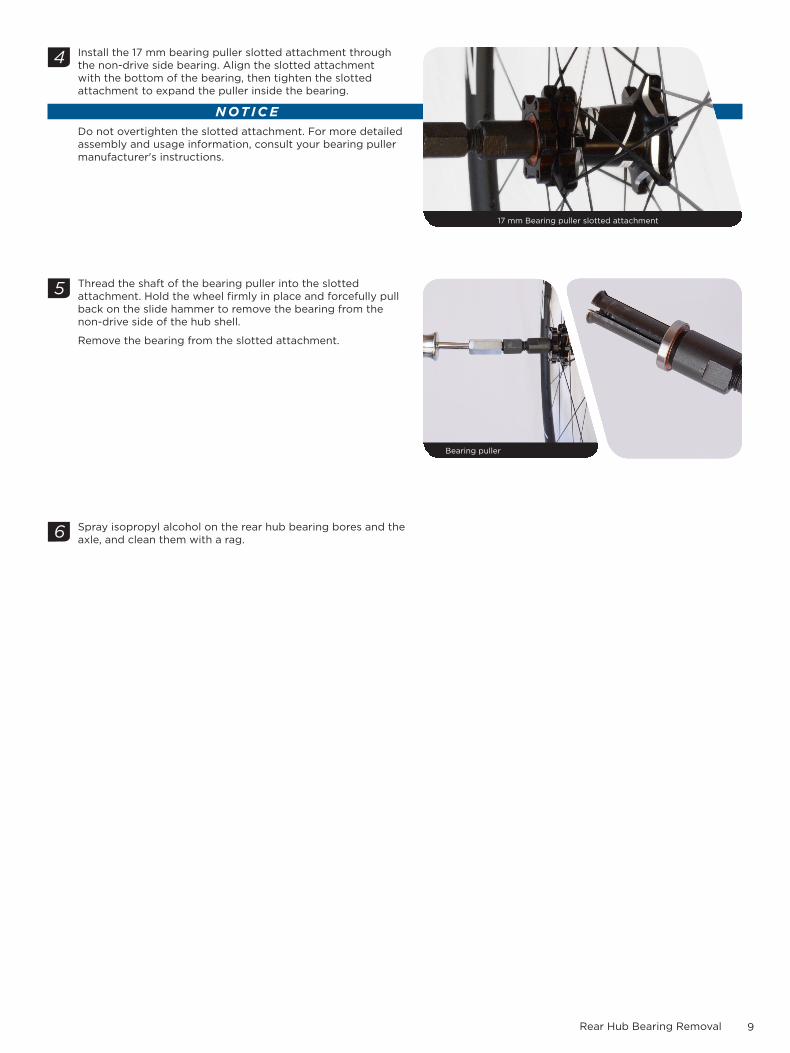
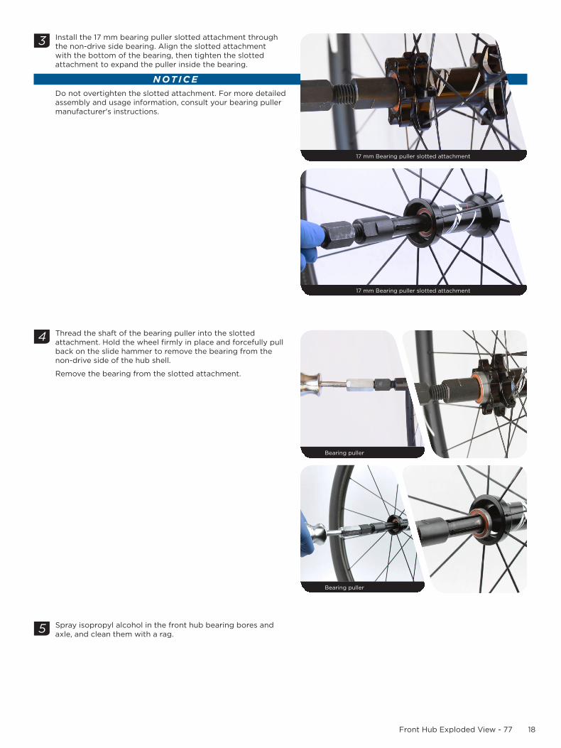
Install the 17 mm bearing puller slotted attachment through the non-drive side bearing. Align the slotted attachment with the bottom of the bearing, then tighten the slotted attachment to expand the puller inside the bearing.
NOTICEDo not overtighten the slotted attachment. For more detailed assembly and usage information, consult your bearing puller manufacturer's instructions.
Thread the shaft of the bearing puller into the slotted attachment. Hold the wheel firmly in place and forcefully pull back on the slide hammer to remove the bearing from the non-drive side of the hub shell.
Remove the bearing from the slotted attachment.
Spray isopropyl alcohol on the rear hub bearing bores and the axle, and clean them with a rag.
4
17 mm Bearing puller slotted attachment
Bearing puller
5
6
Rear Hub Bearing RemovalRear Hub Bearing Removal

10Rear Hub Bearing Installation
R e a r H u b B e a r i n g I n s t a l l a t i o n
NOTICETo prevent damage when pressing the bearings into the rear hub, make sure that the bearing press adapters contact both the inner and outer races of the bearing.
Install a new 61903 bearing into the drive side bearing bore of the hub shell with the orange seal facing outward.
Slide the 6903 bearing adapter onto the threaded rod of the bearing press tool. Insert the threaded rod through the drive side of the hub shell and position the narrow end of the bearing adapter into the center of the bearing.
Slide the second 6903 bearing adapter onto the threaded rod, and position the adapter into the non-drive side hub shell bearing bore.
Thread the bearing press handle onto the threaded rod. Turn the threaded handle clockwise to press the bearing into the drive side bearing bore until it is hand tight.
Remove the bearing press tool.
NOTICEDo not overtighten the bearing.
Install the longer, drive side of the axle through the non-drive side of the rear hub and through the drive side bearing.
1
Drive side 61903 bearing
2
Bearing Press / 6903 Adapter -- 6903 Adapter / Bearing Press
3
11Rear Hub Bearing Installation
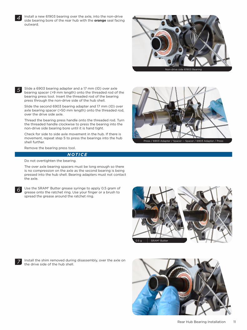
Install a new 61903 bearing over the axle, into the non-drive side bearing bore of the rear hub with the orange seal facing outward.
Slide a 6903 bearing adapter and a 17 mm (ID) over axle bearing spacer (>9 mm length) onto the threaded rod of the bearing press tool. Insert the threaded rod of the bearing press through the non-drive side of the hub shell.
Slide the second 6903 bearing adapter and 17 mm (ID) over axle bearing spacer (>50 mm length) onto the threaded rod, over the drive side axle.
Thread the bearing press handle onto the threaded rod. Turn the threaded handle clockwise to press the bearing into the non-drive side bearing bore until it is hand tight.
Check for side to side axle movement in the hub. If there is movement, repeat step 5 to press the bearings into the hub shell further.
Remove the bearing press tool.
NOTICEDo not overtighten the bearing.
The over axle bearing spacers must be long enough so there is no compression on the axle as the second bearing is being pressed into the hub shell. Bearing adapters must not contact the axle.
Use the SRAM® Butter grease syringe to apply 0.5 gram of grease onto the ratchet ring. Use your finger or a brush to spread the grease around the ratchet ring.
Install the shim removed during disassembly, over the axle on the drive side of the hub shell.
Non-drive side 61903 Bearing 22 mm
4
5
Press / 6903 Adapter / Spacer -- Spacer / 6903 Adapter / Press 22 mm
6
0.5 g SRAM® Butter
7
12Driver Body Installation
D r i v e r B o d y I n s t a l l a t i o n
Zipp recommends replacing the entire driver body assembly if the bearings are worn or any part is damaged. For part numbers, please refer to the Zipp Spare Parts Catalog in the Support section of www.zipp.com.
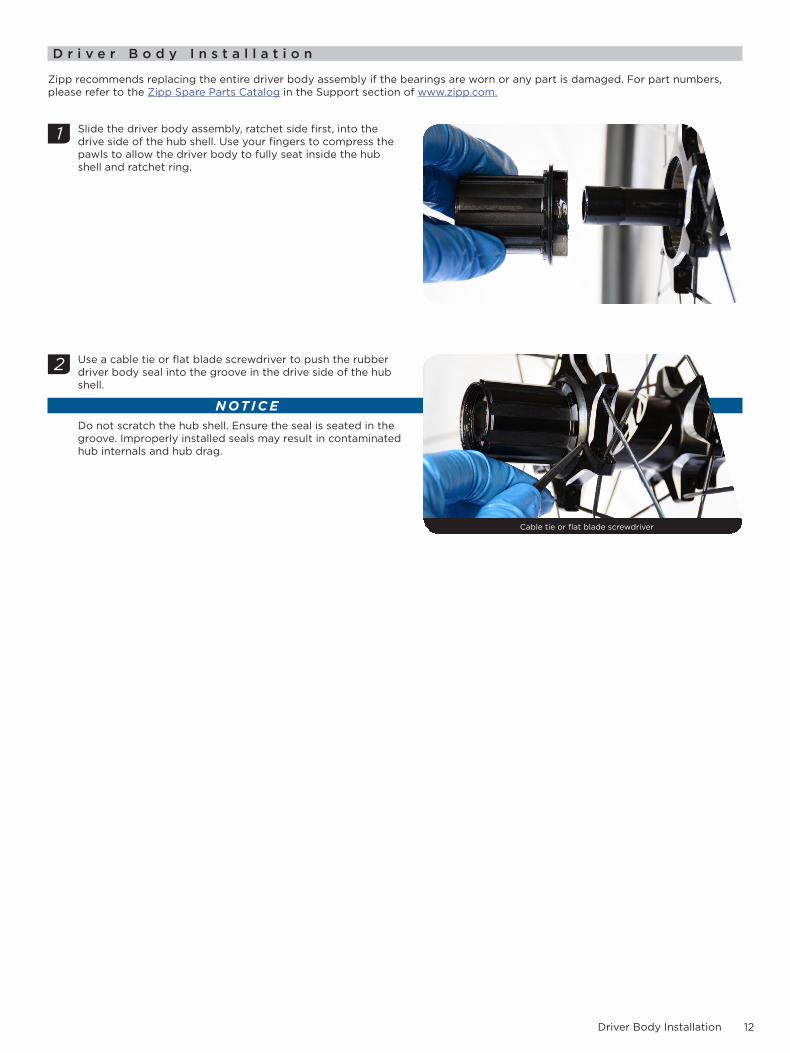
Slide the driver body assembly, ratchet side first, into the drive side of the hub shell. Use your fingers to compress the pawls to allow the driver body to fully seat inside the hub shell and ratchet ring.
Use a cable tie or flat blade screwdriver to push the rubber driver body seal into the groove in the drive side of the hub shell.
NOTICEDo not scratch the hub shell. Ensure the seal is seated in the groove. Improperly installed seals may result in contaminated hub internals and hub drag.
1
2
Cable tie or flat blade screwdriver 22 mm
13End Cap Installation
E n d C a p I n s t a l l a t i o n
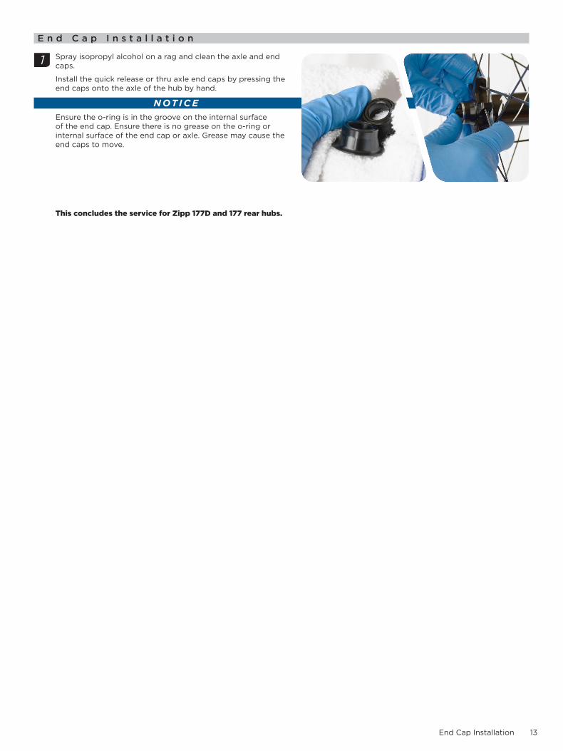
Spray isopropyl alcohol on a rag and clean the axle and end caps.
Install the quick release or thru axle end caps by pressing the end caps onto the axle of the hub by hand.
NOTICEEnsure the o-ring is in the groove on the internal surface of the end cap. Ensure there is no grease on the o-ring or internal surface of the end cap or axle. Grease may cause the end caps to move.
This concludes the service for Zipp 177D and 177 rear hubs.
1
14Front Hub Service
F r o n t H u b S e r v i c eThe hub can be serviced while in the wheel. However, if your spokes or rim are damaged, you can remove the hub from the wheel which will make servicing your hub easier. To remove the hub, use a spoke wrench to de-tension the spokes, then use a pair of metal snips to cut the spokes, remove the hub from the wheel, and remove the spoke ends from the hub (not pictured).
T o o l s N e e d e d f o r S e r v i c e
• Safety glasses• Clean, lint-free rags• Nitrile gloves• Isopropyl alcohol• Bench vise• Aluminum vise blocks• Plastic mallet
• Sealed bearing puller with 17 mm slotted attachment• Sealed bearing press• (2) 6903 bearing press adapters (77D)• (2) 6803 bearing press adapters (77)• (2) 17 mm (ID) over-axle bearing press spacers (min length 9 mm)
R e p l a c e m e n t P a r t s
• (2) 61903 Zipp® 77D hub bearings• (2) 61803 Zipp 77 hub bearings
For part numbers, please refer to the Zipp Spare Parts Catalog in the Support section of www.zipp.com.
SA F E T Y I N S T R U C TI O N SAlways wear nitrile gloves when working with bicycle grease.

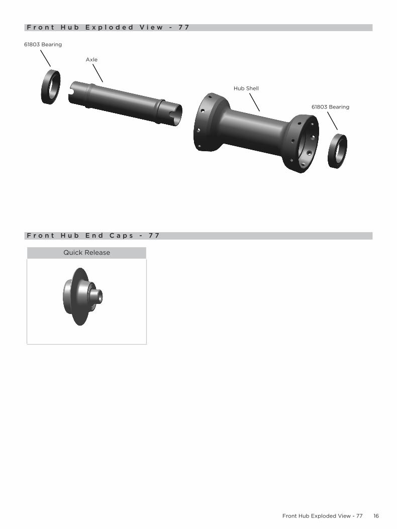
15Front Hub Exploded View - 77D
F r o n t H u b E x p l o d e d V i e w - 7 7 D
F r o n t H u b E n d C a p s - 7 7 D
Quick Release 15 mm x 100 mm 12 mm x 100 mm
Axle
61903 Bearing
Hub Shell
61903 Bearing
16Front Hub Exploded View - 77
F r o n t H u b E x p l o d e d V i e w - 7 7
F r o n t H u b E n d C a p s - 7 7
Quick Release
Axle
61803 Bearing
Hub Shell
61803 Bearing
17Front Hub Bearing Removal
F r o n t H u b B e a r i n g R e m o v a l
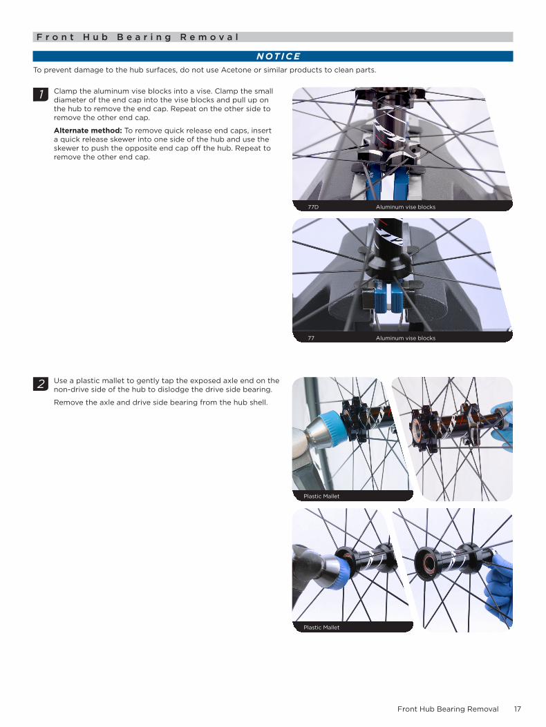
NOTICETo prevent damage to the hub surfaces, do not use Acetone or similar products to clean parts.
Clamp the aluminum vise blocks into a vise. Clamp the small diameter of the end cap into the vise blocks and pull up on the hub to remove the end cap. Repeat on the other side to remove the other end cap.
Alternate method: To remove quick release end caps, insert a quick release skewer into one side of the hub and use the skewer to push the opposite end cap off the hub. Repeat to remove the other end cap.
Use a plastic mallet to gently tap the exposed axle end on the non-drive side of the hub to dislodge the drive side bearing.
Remove the axle and drive side bearing from the hub shell.
1
77D Aluminum vise blocks
77 Aluminum vise blocks
2
Plastic Mallet
Plastic Mallet
18Front Hub Exploded View - 77
Install the 17 mm bearing puller slotted attachment through the non-drive side bearing. Align the slotted attachment with the bottom of the bearing, then tighten the slotted attachment to expand the puller inside the bearing.
NOTICEDo not overtighten the slotted attachment. For more detailed assembly and usage information, consult your bearing puller manufacturer's instructions.
Thread the shaft of the bearing puller into the slotted attachment. Hold the wheel firmly in place and forcefully pull back on the slide hammer to remove the bearing from the non-drive side of the hub shell.
Remove the bearing from the slotted attachment.
Spray isopropyl alcohol in the front hub bearing bores and axle, and clean them with a rag.
3
17 mm Bearing puller slotted attachment
17 mm Bearing puller slotted attachment
Bearing puller
4
Bearing puller
5

19Front Hub Bearing Installation
F r o n t H u b B e a r i n g I n s t a l l a t i o n
NOTICETo prevent damage when pressing the bearings into the front hub, make sure that the bearing press adaptors contact both the inner and outer races of the bearing.
Install a new bearing into the non-drive side bearing bore of the hub shell with the orange seal facing outward.
Slide a bearing adapter onto the threaded rod of the bearing press tool. Insert the threaded rod through the non-drive side of the hub shell and position the narrow end of the bearing adapter into the center of the bearing.
Slide the second bearing adapter onto the threaded rod, and position the adapter into the drive side hub shell bearing bore.
Thread the bearing press handle onto the threaded rod. Turn the threaded handle clockwise to press the bearing into the non-drive side bearing bore until it is hand tight.
Remove the bearing press tool.
NOTICEDo not overtighten the bearing.
1
77D Non-drive side 6903 bearing
77 Non-drive side 6803 bearing
2
Bearing Press / 6903 Adapter -- 6903 Adapter / Bearing press
Bearing press / 6803 Adapter -- 6803 Adapter / Bearing press
20Front Hub Bearing Installation
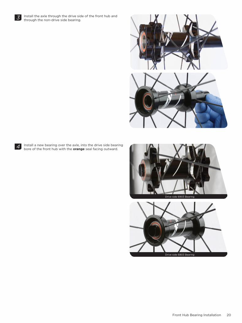
Install the axle through the drive side of the front hub and through the non-drive side bearing.
Install a new bearing over the axle, into the drive side bearing bore of the front hub with the orange seal facing outward.
53
4
Drive side 6903 Bearing
Drive side 6803 Bearing
21Front Hub Bearing Installation
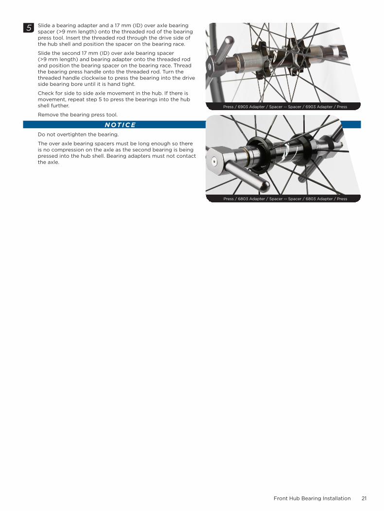
Slide a bearing adapter and a 17 mm (ID) over axle bearing spacer (>9 mm length) onto the threaded rod of the bearing press tool. Insert the threaded rod through the drive side of the hub shell and position the spacer on the bearing race.
Slide the second 17 mm (ID) over axle bearing spacer (>9 mm length) and bearing adapter onto the threaded rod and position the bearing spacer on the bearing race. Thread the bearing press handle onto the threaded rod. Turn the threaded handle clockwise to press the bearing into the drive side bearing bore until it is hand tight.
Check for side to side axle movement in the hub. If there is movement, repeat step 5 to press the bearings into the hub shell further.
Remove the bearing press tool.
NOTICEDo not overtighten the bearing.
The over axle bearing spacers must be long enough so there is no compression on the axle as the second bearing is being pressed into the hub shell. Bearing adapters must not contact the axle.
5
Press / 6903 Adapter / Spacer -- Spacer / 6903 Adapter / Press
Press / 6803 Adapter / Spacer -- Spacer / 6803 Adapter / Press

22End Cap Installation
E n d C a p I n s t a l l a t i o n
Spray isopropyl alcohol on a rag and clean the axle and end caps.
Install the quick release or thru axle end caps by pressing the end caps onto the axle of the hub by hand.
NOTICEEnsure the o-ring is in the groove on the internal surface of the end cap. Ensure there is no grease on the o-ring or internal surface of the end cap or axle. Grease may cause the end caps to move.
This concludes service for Zipp 77D and 77 front hubs.
1

23
“We will revolutionize the relationship that our users have with SRAM products, cultivating a bond between the rider and bicycle. Our technical communication will be delivered in innovative and exciting ways, with deliberation and accuracy
that inspires loyalty and trust across the globe.”
-SRAM TechCom Vision Statement
ASIAN HEADQUARTERS SRAM Taiwan No. 1598-8 Chung Shan Road Shen Kang Hsiang, Taichung City Taiwan R.O.C.
WORLD HEADQUARTERS SRAM LLC
1000 W. Fulton Market, 4th Floor Chicago, Illinois 60607
USA
EUROPEAN HEADQUARTERS SRAM Europe
Paasbosweg 14-16 3862ZS Nijkerk
The Netherlands
www.sram.com