Embed Size (px)
DESCRIPTION
Ericsson RBS6000
Citation preview
RBS 6000 Commissioning Procedure
1 IntroductionThis document describes step-by-step instructions for integration of a RBS 6000 series.
2 Objective
This document serves the purpose of describing the procedure related to theCommissioning and integration of a RBS 6000 series. This first version will concentrate on the RBS 6201, the indoor macro version.
3 PrerequisitesComplete RBS carry-in, installation, and check power system.
4 Tools for Verification
4.1 PC ToolsWindows 7 or Vista, laptop, PCPre-install / pre-configure the following tools according to the documenttitled “EMAS Installation Guide”.� Java plug-in version is 1.5 for ENodeB Element Manager� Internet Explorer or Mozilla Firefox.� HyperTerminal or Putty and serial terminal software� FTP client software installed (Filezilla or Ipswitch WS_FTP Professional) NB! If Filezilla is used, be sure to set the FTP transfer method to Binary.
4.2 Software� The latest RBS Software Packages BP_CXP102083%10_R6T.
� Site specific .xml files.1. xxxxxxSiteInstall (xxxxxx is the Identity of the eNodeB)
4.3 Hardware� Ethernet crossover RJ45 to RJ45 cable for RBS-Thin Client connection (Ethernet).� Serial RS-232C, RJ45-Dsub9 cables for RBS-Thin Client connection.
5 ConfigurationIn this document the following notation is used for commands.
$ te▲log▲readThis would mean that you should enter ’te’ <space key> ’log’ <space key> ’read’and then press <enter key>. $ appears when you open a serial connection andpress the return key.5.1 Prepare for Integration.5.2 Check Miscellaneous Equipment (i.e. TMA/RET)5.3 No alarm on transmission equipment (If Applicable).5.4 Cabling between the Thin Client and RBS: Ethernet connection is made from thelaptop to LMB connector on the DUL interface on the RBS6201. 5.5 Connect serial cable to LMA connector on the DUL interface of the eNodeB RBS 62015.6 Thin Client IP Address Change (see section 7)5.7 Check Serial Connection (HyperTerminal/Putty)
6 Preparing the Laptop
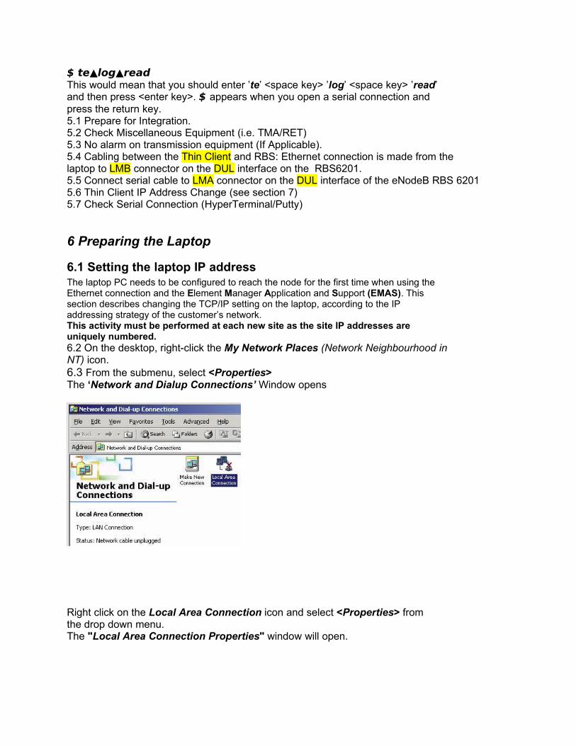
6.1 Setting the laptop IP addressThe laptop PC needs to be configured to reach the node for the first time when using theEthernet connection and the Element Manager Application and Support (EMAS). Thissection describes changing the TCP/IP setting on the laptop, according to the IPaddressing strategy of the customer’s network.This activity must be performed at each new site as the site IP addresses areuniquely numbered.6.2 On the desktop, right-click the My Network Places (Network Neighbourhood inNT) icon.6.3 From the submenu, select <Properties>The ‘Network and Dialup Connections’ Window opens
Right click on the Local Area Connection icon and select <Properties> fromthe drop down menu.The "Local Area Connection Properties" window will open.
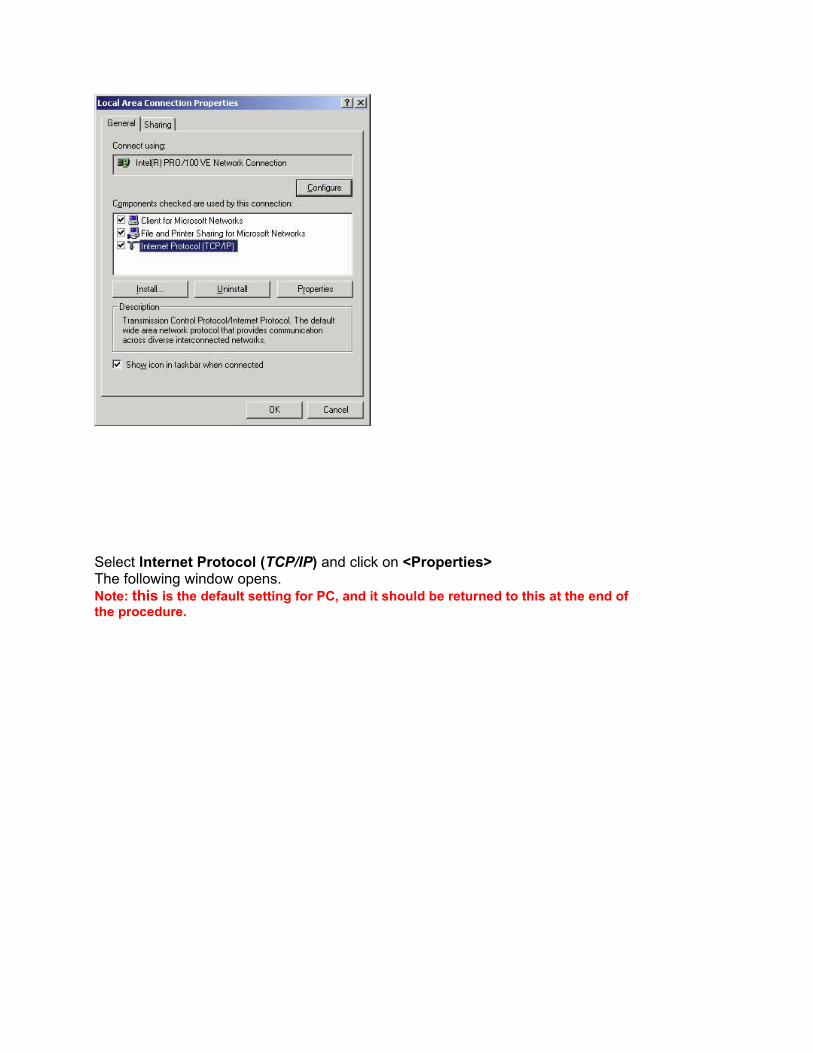
Select Internet Protocol (TCP/IP) and click on <Properties>The following window opens.Note: this is the default setting for PC, and it should be returned to this at the end ofthe procedure.
NB! You can avoid this setting if your PC get routing info from eNB. Check this by open an MS-DOS window (Run… from Start menu on your PC and cmd). If you get the following routing information when writing the command ipconfig in the MS-DOS window, you can proceed without setting the IPv4 address:
IPv4 Address. . . . . . . . . . . : 169.254.33.0Subnet Mask . . . . . . . . . . . : 255.255.0.0Default Gateway . . . . . . . . . : 169.254.1.10
The Laptop PC IP Address is set in this window using the following process,NOTE: The IP address of the Laptop PC (thin client) cannot be the same asthe Ethernet IP address of the RBS node.Networking convention dictates that the commissioning laptop (thin client) addressis equal to the RBS Node Ethernet address incremented by one.
Example (Site specific IP address (i.e. site 139901)� RBS Ethernet IP Address = 10.26.67.254� Laptop PC (thin client) IP Address = 10.26.67.255The Subnet mask can be set as follows.� Subnet Mask = 255.255.0.0
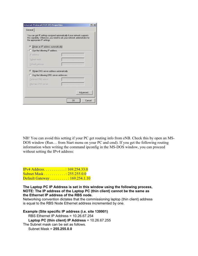
Select 'Use the following IP address' in the TCP/IP properties window.Enter the IP address for the Laptop PC (thin client), and also enter the SubnetMask as detailed above. Check that the 'Use the following DNS serveraddress' is selected and that the address and subnet mask is blank.6.7 Click <OK> close all the windows.6.8 With some operating systems it may be required to restart the Laptop PC (thinclient) to activate the new IP settings.The Laptop PC (thin client) is now configured.
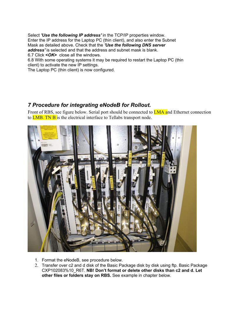
7 Procedure for integrating eNodeB for Rollout.Front of RBS, see figure below. Serial port should be connected to LMA and Ethernet connection to LMB. TN B is the electrical interface to Tellabs transport node.
1. Format the eNodeB, see procedure below.2. Transfer over c2 and d disk of the Basic Package disk by disk using ftp. Basic Package
CXP102083%10_R6T. NB! Don’t format or delete other disks than c2 and d. Let other files or folders stay on RBS. See example in chapter below.
3. Do reload command on serial interface and the node should come up with basic configuration (CV) after a couple of minutes.
4. Start up Element Manager by using the following address in the browser: http://169.254.1.10/em/index.html. Download the Client to your PC and Install it.
5. When the Client is installed, start it form Programs -> EM-Application.6. You can either start RBS Element Manager or RBS Configuraion tool -> Integrate RBS.7. From EMAS click tools in the top tab menu line and choose Configuration tool (only one
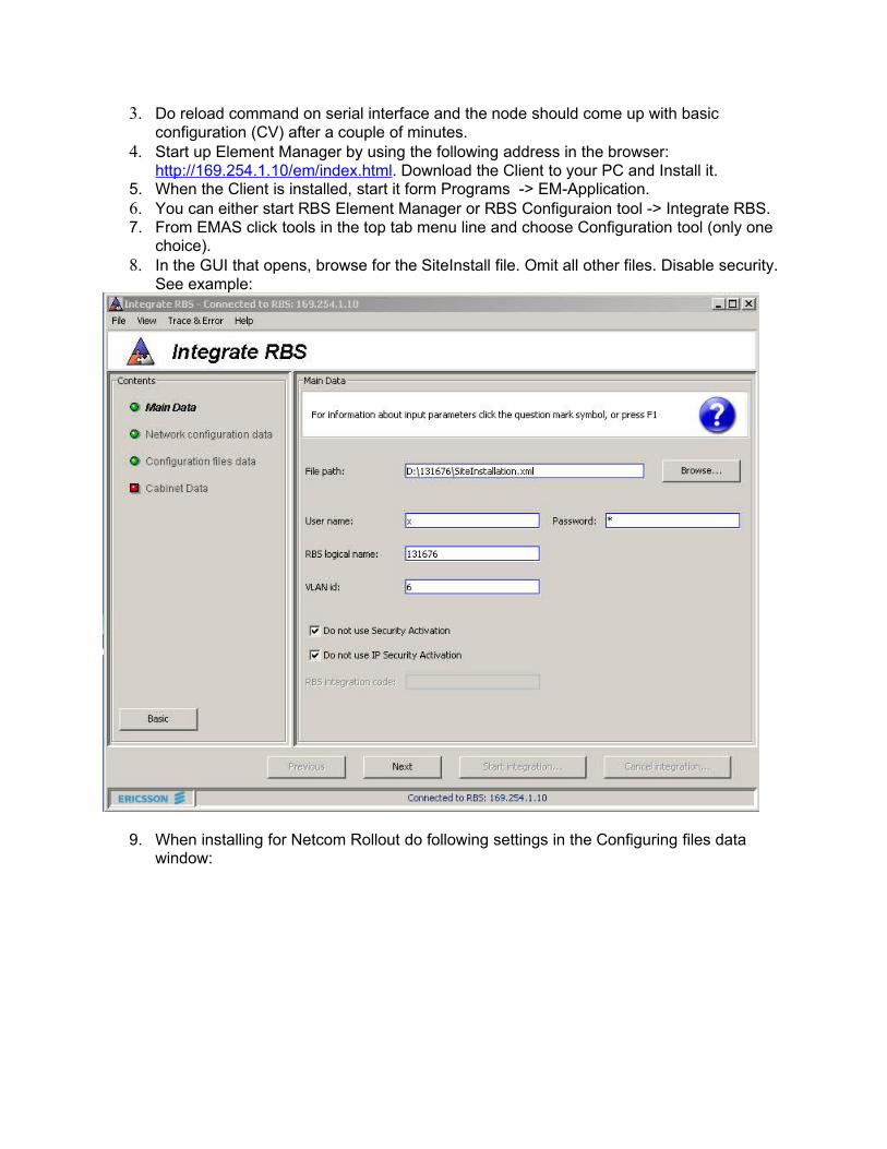
choice).8. In the GUI that opens, browse for the SiteInstall file. Omit all other files. Disable security.
See example:
9. When installing for Netcom Rollout do following settings in the Configuring files data window:
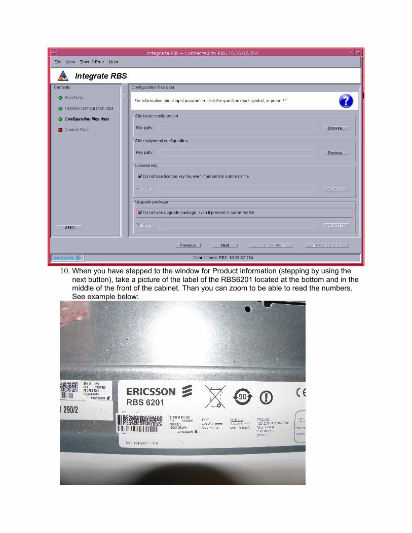
10. When you have stepped to the window for Product information (stepping by using the next button), take a picture of the label of the RBS6201 located at the bottom and in the middle of the front of the cabinet. Than you can zoom to be able to read the numbers. See example below:
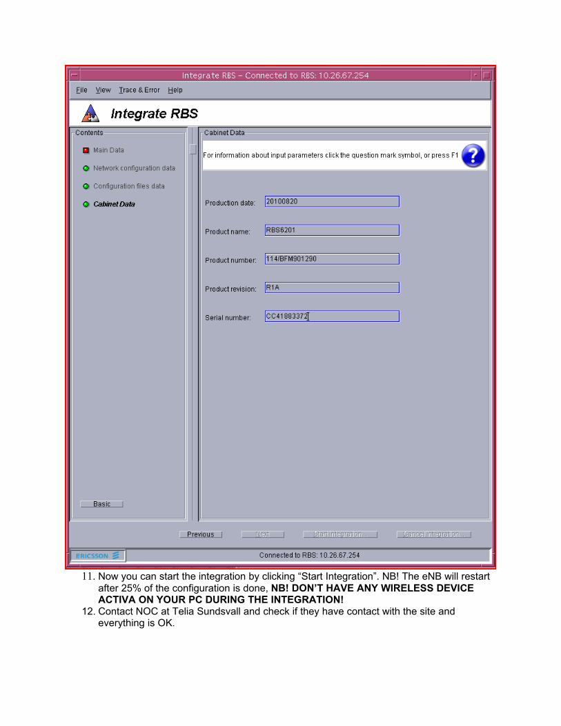
11. Now you can start the integration by clicking “Start Integration”. NB! The eNB will restart after 25% of the configuration is done, NB! DON’T HAVE ANY WIRELESS DEVICE ACTIVA ON YOUR PC DURING THE INTEGRATION!
12. Contact NOC at Telia Sundsvall and check if they have contact with the site and everything is OK.
8 Formatting the RBS 6000This step requires a serial connection to the DUL NB! Specific pinconfig of the RS232 connector. See pinlayout on own sheet.HyperTerminal or Puttyl serial terminal software (Go to Section 17.1 forHyperTerminal Setup Instructions Go to Section 17.2 for Putty7.1 Note: As detailed in this procedure the RBS 6000 will be placed into a BACKUPmode, this is an 'idle' mode where the RBS is in a state where it is not in serviceor executing any of its own processes.Force the RBS into BACKUP mode using the commands in the serial windowbelow,$ reload▲- -The expected response that will be contained in the serial window is “Stop dueto remain in backup set”Now format the RBS hard disks using the following commands, responding withY when prompted to continue. Note: All data on the hard disk will bedestroyed.$ formathd▲/d Y $ formathd▲/c2 Y
Once the second format command has completed enter the following command$ reload▲- - The expected response that will be contained in the serial window is “Stop dueto remain in backup set”
7.2 With the RBS 6000 in the “BACKUP” mode, proceed to the next section to set theRBS 6000 Ethernet IP address, using the following format.$ ifconfig le0 <RBS IP_address> e.g. $ ifconfig▲le0▲169.254.1.10 (169.254.1.10 is the standard address for the eNodeB when delivered from NPC (Node Production Centre)Verify the IP address that has been input by using the following command, thereply will show the IP address information that has been set. If the information isincorrect set the IP address again. Example printout following the 'ifconfig' command.
$ ifconfig le0ip-address: 169.254.1.10 subnetmask: 255.255.0.0 broadcast: 169.254.255.254
Do reload now and eNB should come up with basic_cv. The distribution of SW take a couple of minutes and the following status shows that it is ready:
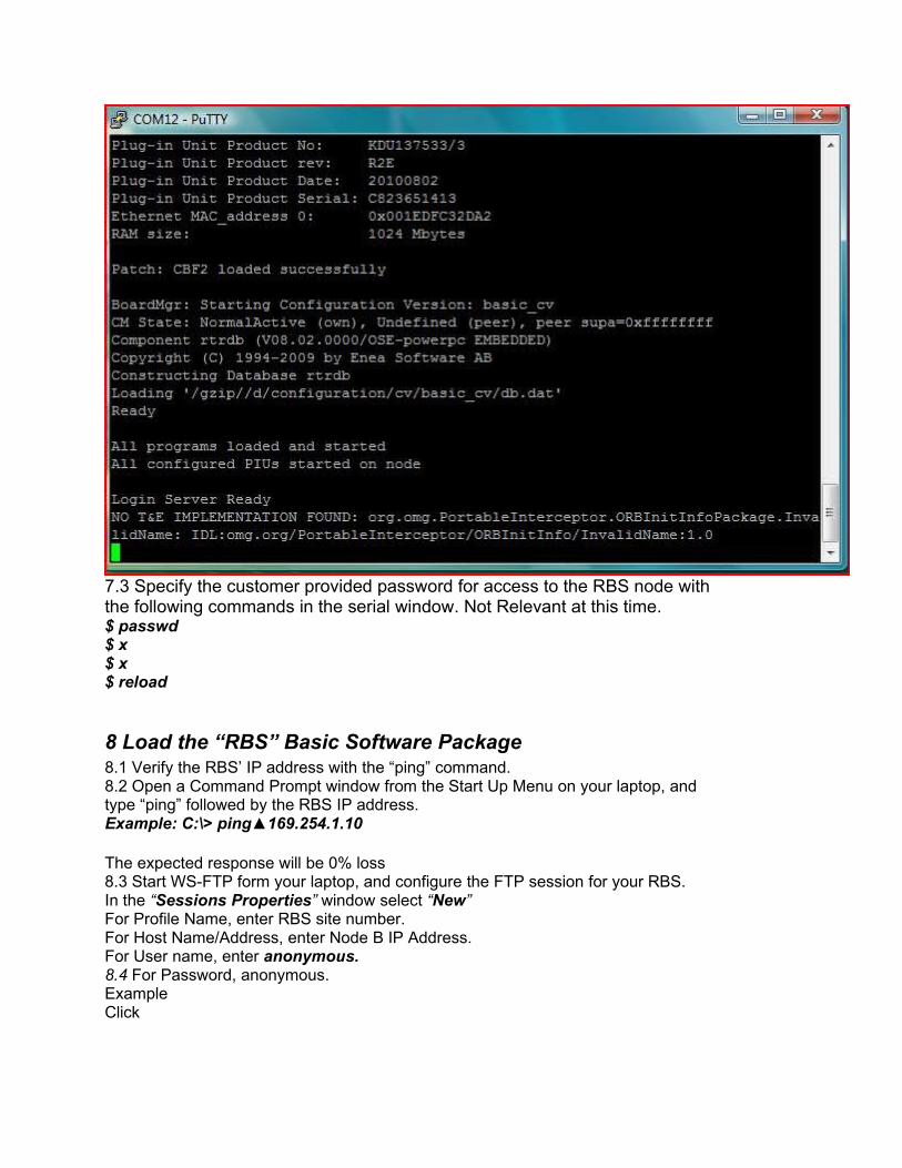
7.3 Specify the customer provided password for access to the RBS node withthe following commands in the serial window. Not Relevant at this time.$ passwd$ x$ x$ reload
8 Load the “RBS” Basic Software Package8.1 Verify the RBS’ IP address with the “ping” command.8.2 Open a Command Prompt window from the Start Up Menu on your laptop, andtype “ping” followed by the RBS IP address.Example: C:\> ping▲169.254.1.10
The expected response will be 0% loss8.3 Start WS-FTP form your laptop, and configure the FTP session for your RBS.In the “Sessions Properties” window select “New”For Profile Name, enter RBS site number.For Host Name/Address, enter Node B IP Address.For User name, enter anonymous.8.4 For Password, anonymous.ExampleClick
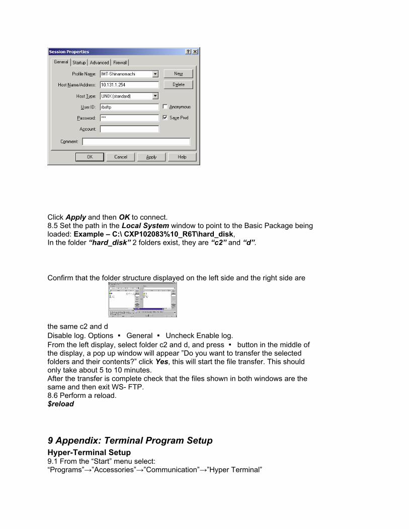
Click Apply and then OK to connect.8.5 Set the path in the Local System window to point to the Basic Package beingloaded: Example – C:\ CXP102083%10_R6T\hard_disk,In the folder “hard_disk” 2 folders exist, they are “c2” and “d”.
Confirm that the folder structure displayed on the left side and the right side are
the same c2 and dDisable log. Options � General � Uncheck Enable log.From the left display, select folder c2 and d, and press � button in the middle ofthe display, a pop up window will appear ”Do you want to transfer the selectedfolders and their contents?” click Yes, this will start the file transfer. This shouldonly take about 5 to 10 minutes.After the transfer is complete check that the files shown in both windows are thesame and then exit WS- FTP.8.6 Perform a reload.$reload
9 Appendix: Terminal Program SetupHyper-Terminal Setup9.1 From the “Start” menu select:“Programs”→”Accessories”→”Communication”→”Hyper Terminal”
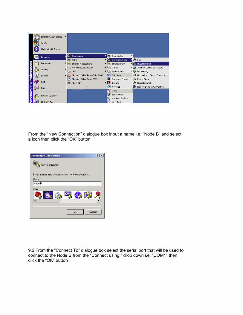
From the “New Connection” dialogue box input a name i.e. “Node B” and selecta icon then click the “OK” button
9.2 From the “Connect To” dialogue box select the serial port that will be used toconnect to the Node B from the “Connect using:” drop down i.e. “COM1” thenclick the “OK” button
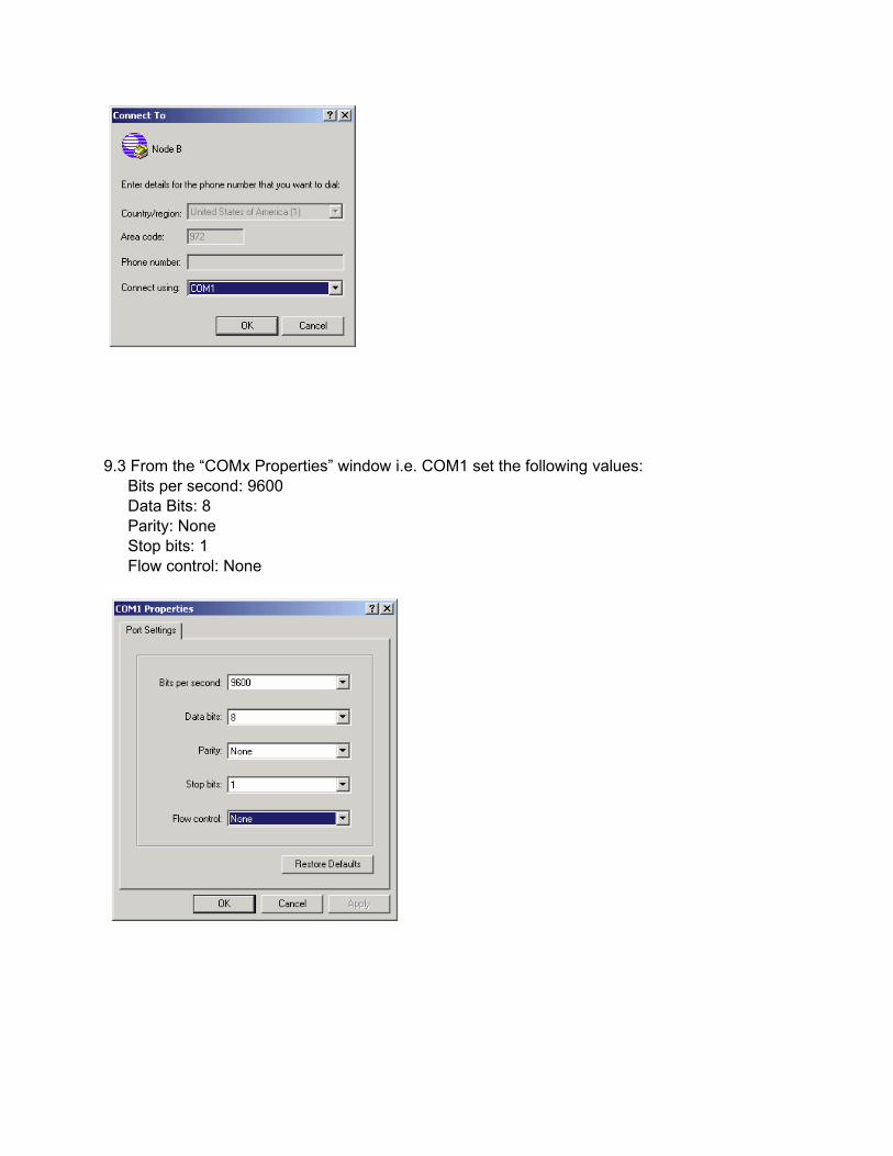
9.3 From the “COMx Properties” window i.e. COM1 set the following values:� Bits per second: 9600� Data Bits: 8� Parity: None� Stop bits: 1� Flow control: None
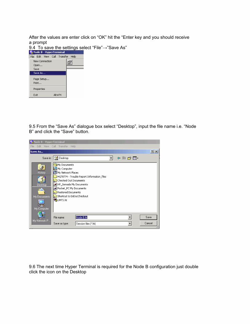
After the values are enter click on “OK” hit the “Enter key and you should receivea prompt9.4 To save the settings select “File”→”Save As”
9.5 From the “Save As” dialogue box select “Desktop”, input the file name i.e. “NodeB” and click the “Save” button.
9.6 The next time Hyper Terminal is required for the Node B configuration just doubleclick the icon on the Desktop
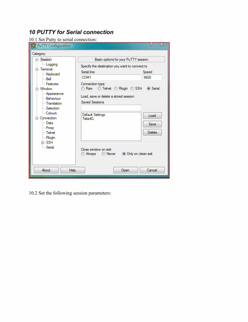
10 PUTTY for Serial connection10.1 Set Putty to serial connection:
10.2 Set the following session parameters:
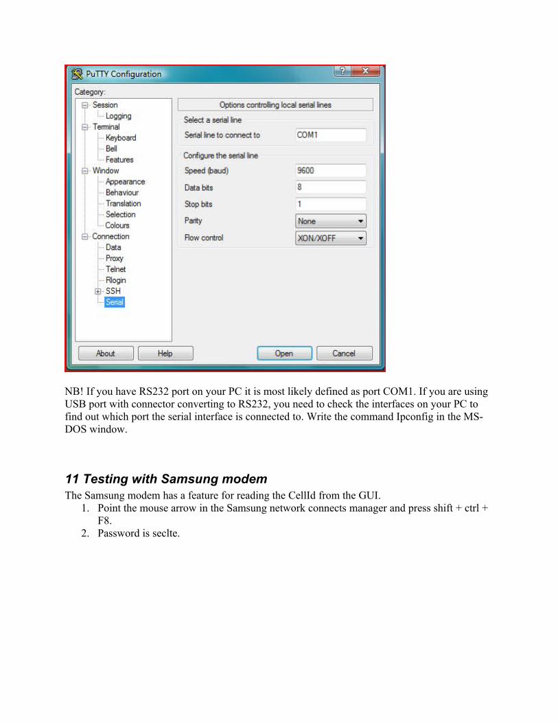
NB! If you have RS232 port on your PC it is most likely defined as port COM1. If you are using USB port with connector converting to RS232, you need to check the interfaces on your PC to find out which port the serial interface is connected to. Write the command Ipconfig in the MS-DOS window.
11 Testing with Samsung modemThe Samsung modem has a feature for reading the CellId from the GUI.
1. Point the mouse arrow in the Samsung network connects manager and press shift + ctrl + F8.
2. Password is seclte.
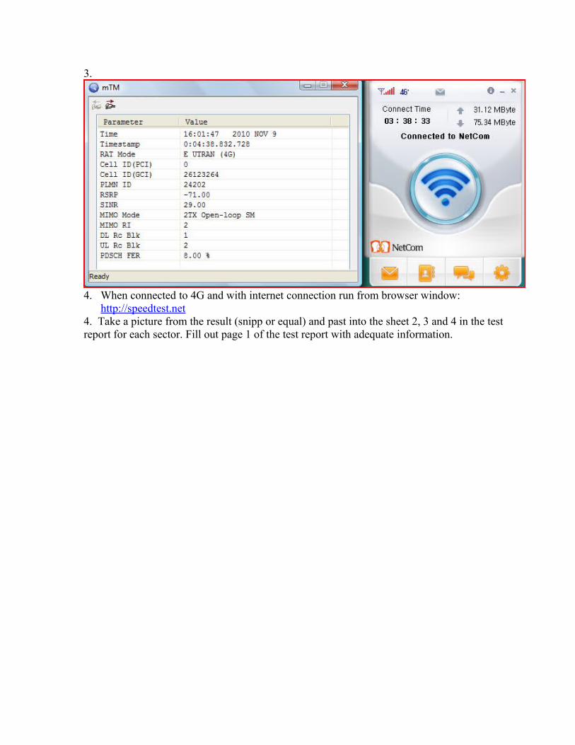
3.
4. When connected to 4G and with internet connection run from browser window: http://speedtest.net
4. Take a picture from the result (snipp or equal) and past into the sheet 2, 3 and 4 in the test report for each sector. Fill out page 1 of the test report with adequate information.
![[XLS] · Web viewRBS 6102 S-01 B1m N 001-A06988 RBS 6202 S-01 B1m N 001-A06989 RBS 6131 S-01 B1m N 001-A06990 RBS 6000 S-11 B1m 001-A03151 5M00X7W 2152.5~2167.5MHz (100kHz間隔151波)](https://img.dokumen.tips/doc/110x75/5ad10f687f8b9a72118b9ed6/xls-viewrbs-6102-s01-b1m-n-001-a06988-rbs-6202-s01-b1m-n-001-a06989-rbs.jpg)