Embed Size (px)
Citation preview

Digital Clamp Multimeters
72-7224 / 72-7226

Table of Contents
OverviewInspectionSafety InformationRules For Safe OperationInternational Electrical SymbolsThe Meter StructureRotary SwitchFunction ButtonsButton UseDisplay SymbolsMeasurement Operation A. DC/AC Voltage Measurement B. Measuring Resistance C. Testing Diodes D. Testing for Continuity E. Frequency Measurement F. Duty Cycle Measurement G. DC/AC Current Measurement
3456910111214151818202224262830
Title Page
Model 72-7224 / 72-7226: OPERATING MANUAL
1

Sleep ModeSpecifications A. General Specifications B. Environmental RequirementsAccuracy Specifications A. DC Voltage B. AC Voltage C. Resistance D. Diode Test E. Continuity Test F. Frequency G. Duty Cycle H. DC Current I. AC CurrentMaintenance A. General Service B. Replacing the Battery
3233333435353637373839404042444445
Title Page
Model 72-7224 / 72-7226: OPERATING MANUAL
2

OverviewThis Operating Manual covers information on safety and cautions. Please read therelevant information carefully and observe all the Warnings and Notes strictly.
WarningTo avoid electric shock or personal injury, read the “Safety Information” and “Rulesfor Safe Operation” carefully before using the Meter.
Digital Clamp Multimeter Models 72-7224 and 72-7226 (hereafter referred to as “theMeter”) are 3 3/4 digits with precise operation, fashionable structure and highly reliablemeasuring instrument. The Meter uses large scale of integrated circuit with doubleintegrated A/D converter as its core and has full range overload protection.
Both models measure AC/DC Voltage, AC/DC Current, Frequency, Duty Cycle,Resistance, Diodes and Continuity, and also include Data Hold, Sleep Mode andRelative Mode features.
Model 72-7226 also provides True RMS measurement.
Model 72-7224 / 72-7226: OPERATING MANUAL
3

InspectionOpen the package case and take out the Meter. Check the following items carefullyto see if any items are missing or damaged.
Item Description Qty
1234
English Operating ManualTest LeadCarrying Bag9V Battery (NEDA1604, 6F22 or 006P)
1 piece1 pair1 piece1 piece
In the event you find any items missing or damaged, please contact your dealerimmediately.
Model 72-7224 / 72-7226: OPERATING MANUAL
4

Safety InformationThis Meter complies with the standards IEC61010: in pollution degree 2, overvoltagecategory (CAT. II 600V, CAT. III 300V) and double insulation.
CAT. II: Local level, appliance, PORTABLE EQUIPMENT etc., with smaller transientovervoltages than CAT. III.CAT. III: Distribution level, fixed installation, with smaller transient overvoltages thanCAT. IV
Use the Meter only as specified in this operating manual, otherwise the protectionprovided by the Meter may be impaired.
In this manual, a Warning identifies conditions and actions that pose hazards to theuser, or may damage the Meter or the equipment under test.
A Note identifies the information that user should pay attention to.
International electrical symbols used on the Meter and in this Operating Manual areexplained on page 9.
Model 72-7224 / 72-7226: OPERATING MANUAL
5

Rules For Safe Operation
WarningTo avoid possible electric shock or personal injury, and to avoid possible damageto the Meter or to the equipment under test, adhere to the following rules:
Before using the Meter inspect the case. Do not use the Meter if it is damagedor the case (or part of the case) is removed. Look for cracks or missing plastic. Pay attention to the insulation around the connectors.Inspect the test leads for damaged insulation or exposed metal. Check the testleads for continuity. Replace damaged test leads with identical model numberor electrical specifications before using the Meter.Do not apply more than the rated voltage, as marked on the Meter, between theterminals or between any terminal and ground. If the value to be measured isunknown, use the maximum measurement position and reduce the range stepby step until a satisfactory reading is obtained.When measurement has been completed, disconnect the connection betweenthe test leads and the circuit under test, remove the test leads away from theinput terminals of the Meter and turn the Meter power off.
l
l
l
l
Model 72-7224 / 72-7226: OPERATING MANUAL
6
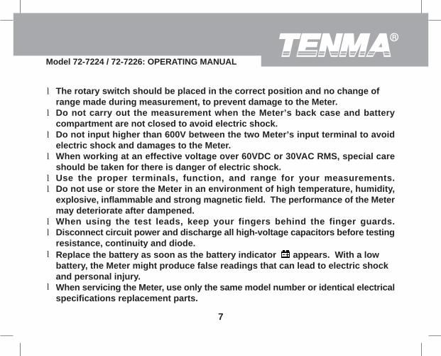
The rotary switch should be placed in the correct position and no change ofrange made during measurement, to prevent damage to the Meter.Do not carry out the measurement when the Meter’s back case and batterycompartment are not closed to avoid electric shock.Do not input higher than 600V between the two Meter’s input terminal to avoidelectric shock and damages to the Meter.When working at an effective voltage over 60VDC or 30VAC RMS, special careshould be taken for there is danger of electric shock.Use the proper terminals, function, and range for your measurements.Do not use or store the Meter in an environment of high temperature, humidity,explosive, inflammable and strong magnetic field. The performance of the Metermay deteriorate after dampened.When using the test leads, keep your fingers behind the finger guards.Disconnect circuit power and discharge all high-voltage capacitors before testingresistance, continuity and diode.Replace the battery as soon as the battery indicator appears. With a lowbattery, the Meter might produce false readings that can lead to electric shockand personal injury.When servicing the Meter, use only the same model number or identical electricalspecifications replacement parts.
l
l
l
l
ll
ll
l
l
Model 72-7224 / 72-7226: OPERATING MANUAL
7

The internal circuit of the Meter shall not be altered at will to avoid damage ofthe Meter and any accident.Soft cloth and mild detergent should be used to clean the surface of the Meterwhen servicing. No abrasive and solvent should be used to prevent the surfaceof the Meter from corrosion, damage and accident.The Meter is suitable for indoor use.Turn the Meter off when it is not in use and take out the battery when not usingfor a long time.Periodically check the battery as it may leak after some time. If leakage is apparent,the battery should be immediately replaced to prevent damage to theMeter.
l
l
ll
l
Model 72-7224 / 72-7226: OPERATING MANUAL
8

International Electrical Symbols
AC (Alternating Current)DC (Direct Current)AC or DCGroundDouble InsulatedWarning. Refer to the Operating ManualLow BatteryContinuity TestDiodeFuseApplication around and removal from HAZARDOUS LIVEconductors is permitted.Conforms to Standards of European Union
Model 72-7224 / 72-7226: OPERATING MANUAL
9

The Meter Structure (see figure 1)
(figure 1)
Input TerminalsLCD DisplayFunction ButtonsRotary SwitchTrigger: press the lever to open the transformerjaws. When the pressure on the lever is released,the jaws will close.Hand Guards: to protect user’s hand from touchingthe dangerous area.Transformer Jaw: designed to pick up the AC andDC current flowing through the conductor. Theconductor under test should pass perpendicularthrough the jaw.
1.2.3.4.5.
6.
7.
Model 72-7224 / 72-7226: OPERATING MANUAL
10

Rotary SwitchThe following table provides information regarding the Rotary Switch positions.
Rotary Switch PositionPower is turned offAC or DC voltage measurementResistance measurement : Diode test : Continuity testFrequency Measurement and DutyMeasurementAC and DC current measurement range
FunctionOFFV
Hz / Duty%
40A 400A&
/
Model 72-7224 / 72-7226: OPERATING MANUAL
11

Function ButtonsThe following table provides information regarding the rotary switch positions.
Button Operation Performed Press HOLD to enter the Hold mode in any mode, the Meter will beep to confirm. Press HOLD again to exit the Hold mode, the Meter will again beep to confirm.At and range: The Meter is defaults to auto ranging mode. Press the REL key to select manual ranging mode. When the Meter is at manual ranging mode, press to step down the range.At range: Press to enter the REL mode. It subtracts a stored value from the present measurement value and displays a result.At Hz/Duty% range: Press to switch between Hz measurement mode and Duty % measurement mode.
l
l
l
l
ll
l
HOLD
REL V
A
Model 72-7224 / 72-7226: OPERATING MANUAL
12

Button Operation PerformedSELECT Press SELECT button to select the alternate functions marked in
blue colour on the Meter’s faceplate including , , 40 , and 400 .
If the meter enters sleep mode, press and hold the SELECT button to reactivate meter.
l
l
VA A
Model 72-7224 / 72-7226: OPERATING MANUAL
13

Function Button UseNot every function button is used in every rotary switch position. The table belowindicates which button can be used in which switch position.
Rotary Switch Positions
Function ButtonsSELECT REL HOLD
llllll
ll
lll
N/A
l
l
ll
N/A
N/A
V
Hz / Duty%40A
400A
/
Model 72-7224 / 72-7226: OPERATING MANUAL
14

Display Symbols (see figure 2)
(figure 2)
4
1
2
3 5
6
8 9
10
1213
14
16
7
11
15
Model 72-7224 / 72-7226: OPERATING MANUAL
15

Number Meaning123
4
56789
ACDC
SymbolIndicator for AC voltage or currentIndicator for DC voltageThe battery is low.Warning: To avoid false readings, which could lead topossible electric shock or personal injury, replace thebattery as soon as the battery indicator appears.The Meter is in the auto range mode in which the Meterautomatically selects the range with the best resolution.Diode test.The continuity buzzer is onIndicator for Duty.Data hold is activeIndicator for REL mode
%
Model 72-7224 / 72-7226: OPERATING MANUAL
16

Number Meaning10
111213
141516
,k ,M
HzA
mV, V
TRMSOL
Symbol: Ohm. The unit of resistance.
k : Kilohm. 1x10³ or 1000 ohmsM : Megohm. 1x10⁶ or 1,000,000 ohmsThe unit of FrequencyAmperes (amps). The unit of current.Volts. The unit of voltage.mV: Millivolt. 1x10⁻³ or 0.001 voltsIndicates negative readingIndicator for TRMS modeThe input value is too large for the selected range
Model 72-7224 / 72-7226: OPERATING MANUAL
17

Measurement Operation
A. DC/AC Voltage Measurement (see figure 3)
(figure 3)
Warning
To avoid damage to the meter, or risk of personalinjury, do not attempt to measure higher than 600VAC/DC, although readings may be obtained.
The DC Voltage ranges are:400mV, 4V, 40V, 400V and 600V.
The AC Voltage ranges are:4V, 40V, 400V and 600V.
To measure DC voltage, connect the Meter as follows:
Insert the red test lead into the Hz Duty% terminal and the black test leadinto the COM terminal.
1.
Red Black
Model 72-7224 / 72-7226: OPERATING MANUAL
18

When DC/AC voltage measurement has been completed, disconnect the testleads from the circuit under test, and remove them from the input terminals.
Set the rotary switch to . DC mesaurement mode and auto ranging is a default.Press SELECT to switch to AC measurement mode or press to switch tomanual ranging measurement mode.Connect the test leads across with the object being measured.The measured value shows on the display.
2.
3.
VREL
Model 72-7224 / 72-7226: OPERATING MANUAL
19
Notel

B. Measuring Resistance (see figure 4)
(figure 4)
Red Black
WarningTo avoid damage to the Meter or to the devicesunder test, disconnect circuit power and dischargeall the high-voltage capacitors before measuringresistance.
The resistance ranges are:400 , 4k , 40k ,400k ,4M and 40M .
To measure resistance, connect the Meter as follows:
Insert the red test lead into the Hz Duty% terminal and the black test lead into theCOM terminal.
1.
2.
3.
Set the rotary switch to . Resistance measurement is default to auto range mode,press to switch to manual ranging measurement mode.Connect the test leads across with the object being measured.The measured value shows on the display.
REL
Model 72-7224 / 72-7226: OPERATING MANUAL
20

For precise reading, the device under test should first be removed from its circuit.When resistance measurement has been completed, disconnect the test leadsfrom the circuit under test, and remove them from the input terminals.
Model 72-7224 / 72-7226: OPERATING MANUAL
21
Notell

C. Testing Diodes (see figure 5)
WarningTo avoid damage to the Meter or to the devicesunder test, disconnect circuit power and dischargeall the high-voltage capacitors before testingdiodes.
Use the diode test to check diodes, transistors, andother semiconductor devices. The diode test sendsa current through the semicondutor junction, thenmeasure the voltage drop across the junction. Agood silicon junction drops between 0.5V and 0.8V.
To test the diode out of a circuit, connect the Meteras follows:
Insert the red test lead into the Hz Duty% terminal and the black test leadinto the COM terminal.
1.
(figure 5)
Red Black
Model 72-7224 / 72-7226: OPERATING MANUAL
22

To obtain a more precise reading, You could removing the object from its circuitwill allow more accurate measurement.When diode testing has been completed, disconnect the test leads from the circuitunder test, and remove them from the input terminals.
Set the rotary switch to . Diode measurement mode is a default or presssSELECT to select measurement mode.For forward voltage drop readings on any semiconductor component, place thered test lead on the component’s anode and place the black test lead on thecomponent’s cathode.
2.
3.
Model 72-7224 / 72-7226: OPERATING MANUAL
23
Notel
l

D. Testing for Continuity (see figure 6)
(figure 6)
Red Black
WarningTo avoid damage to the Meter or to the devicesunder test, disconnect circuit power and dischargeall the high-voltage capacitors before measuringcontinuity.
To test for continuity, connect the Meter as follows:Insert the red test lead into the Hz Duty% terminal and the black test lead into theCOM terminal.Set the rotary switch to and press SELECTbutton to select measurement mode.The buzzer sounds if the resistance of a circuitunder test is less than 50
1.
2.
3.
4.
5.
The buzzer may or may not sound if the resistance of a circuit under test is between50 to 100The buzzer will not sound if the resistance of a circuit under test is higher than100
Model 72-7224 / 72-7226: OPERATING MANUAL
24

When continuity testing has been completed, disconnect the test leads from thecircuit under test, and remove them from the input terminals.
Model 72-7224 / 72-7226: OPERATING MANUAL
25
Notel

E. Frequency Measurement (see figure 7)
Warning
To avoid damage to the meter, or risk of personalinjury, do not attempt to measure higher than 600VAC/DC, although readings may be obtained.
The frequency ranges are:10Hz, 100Hz, 1kHz, 10kHz, 100kHz, 1MHz and10MHz.
To measure frequency, connect the Meter as follows:Insert the red test lead into the Hz Duty% terminal and the black test lead into theCOM terminal.
1.
2.3.
(figure 7)
Red Black
Set the rotary switch to Hz.Connect the test leads across with the object being measured.The measured value shows on the display.
Model 72-7224 / 72-7226: OPERATING MANUAL
26

When frequency measurement has been completed, disconnect the test leadsfrom the circuit under test, and remove them from the input terminals.
Model 72-7224 / 72-7226: OPERATING MANUAL
27
Notel

F. Duty Cycle Measurement (see figure 8)
(figure 8)
Red Black
Warning
To avoid damage to the meter, or risk of personalinjury, do not attempt to measure higher than600V AC/DC, although readings may be obtained.
The duty cycle range is: 0.1%~99.9%.
To measure duty cycle, connect the Meter as follows:
Insert the red test lead into the Hz Duty% terminal and the black test lead into theCOM terminal.
1.
2.
3.
RELSet the rotary switch to Hz and press to select Duty Cycle measurementmode.Connect the test leads across with the object being measured.The measured value shows on the display.
Model 72-7224 / 72-7226: OPERATING MANUAL
28

When duty cycle measurement has been completed, disconnect the test leadsfrom the circuit under test, and remove them from the input terminals.
Model 72-7224 / 72-7226: OPERATING MANUAL
29
Notel

G. DC/AC Current Measurement (see figure 9)
The measuremnet ranges of current are: 40.00and 400.0 .
To measure current, do the following:1.
2.
3.4.
(figure 9)
Set the rotary switch to 40 or 400 . DCmeasuremnet mode is a default. Press SELECT toswitch between DC and AC measurement mode.Hold the Meter tight, don’t release. The Hallcomponents are very senstive not only to the magnetbut also to heat and machines reaction force. It isimportant that the meter be held firmly and steadilyduring current measurement.Press the lever to open the transformer jaw.
AA
A A
Center the conductor within the transformer jaw, then release the Meter slowly untilthe trasnformer jaw is completely closed, For best accuracy, it is important thatthe conductor under test be placed in the center of the transformer jaw, perpendicularto the jaw.Measure only one conductor at a time, multiple conductors in thetransformer clamp will cause inaccuracy.
40A400A
Model 72-7224 / 72-7226: OPERATING MANUAL
30

Press to subtract a stored value from the present measurement value anddisplay a result.When current measurement has been completed, disconnect the connectionbetween the conductor under test and the jaw, press the lever to open thetransformer jaw again and remove the jaw from the conductor under test.
REL
Model 72-7224 / 72-7226: OPERATING MANUAL
31
Notel
l
Sleep ModeTo preserve battery life, the Meter automatically turns off after 15 minutes of inactivity.
The Meter can be activated by pressing any button or changing the position of therotary switch.
Approximately one minute before entering sleep mode, the buzzer will beep fivetimes. Immediately before entering sleep mode, the buzzer will provide one longbeep.
To disable the Sleep Mode function, press and hold SELECT button while turning onthe Meter.
Model 72-7224 / 72-7226: OPERATING MANUAL
32

Specifications
A. General Specifications:
Maximum Voltage between any Terminals and ground: Refer to different rangeinput protection voltage.Display: 3 3/4 digits LCD display, Maximum display 3999Polarity: Automatically display.Overload: Display OL or –OLLow battery: DisplayMeasurement Speed: Updates 3 times/second.Measuremnet Deviation: The conductor being meaured is not placed in the centerof the jawt during AC/DC current measurement, it will cause extra 1% deviationbased on the stated accuracy.Drop Test: 1 meter drop test passed.Max. Jaw Size: 1.1" (28mm) diameter.Projected Max. Current conductor size: 1.0" (26mm) diameter.Power: 1 x 9V battery (NEDA1604 or 6F22 or 006P)
l
llllll
llll
Model 72-7224 / 72-7226: OPERATING MANUAL
33

Battery Life: typically 150hours (alkaline battery)Sleep Mode (can be disabled)Dimensions (H x W x L): 208mm x 76mm x 30mm.Weight: Approximate 260g (battery included)
llll
B. Environmental RequirementsThe Meter is suitable for indoor use.Altitude: Operating: 2000m Storage: 10000mSafety/ Compliances: IEC 61010 CAT.II 600V, CAT.III 300V over voltage anddouble insulation standard.Temperature and humidity:Operating: 0ºC~30ºC ( 85%R.H);
30ºC~40ºC ( 75%R.H); 40ºC~50ºC ( 45%R.H); Storage: -20ºC~+60ºC ( 85%R.H)
ll
l
l
Note: Use near strong electromagnetic fields may cause inaccurate and undesirablereadings.
Model 72-7224 / 72-7226: OPERATING MANUAL
34
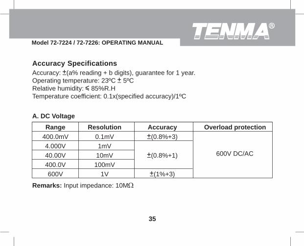
Accuracy SpecificationsAccuracy: (a% reading + b digits), guarantee for 1 year.Operating temperature: 23ºC 5ºCRelative humidity: 85%R.HTemperature coefficient: 0.1x(specified accuracy)/1ºC
A. DC Voltage
Range Resolution Accuracy Overload protection400.0mV4.000V40.00V400.0V600V
0.1mV1mV
10mV100mV
1V
(0.8%+3)
(0.8%+1)
(1%+3)
600V DC/AC
Remarks: Input impedance: 10M
Model 72-7224 / 72-7226: OPERATING MANUAL
35

B. AC Voltage
Range Resolution Accuracy Overload protection4.000V40.00V400.0V600V
1mV10mV
100mV1V
(1%+5)
(1.2%+5)
600V DC/AC
Remarks:Input impedance: 10M // less than 100pFFrequency response: 40Hz~400Hz.Change to AC:
lll
Change to AC by using average response method. Input sine wave, then adjustthe reading until it is same as the effective value.
Combine AC and True RMS response method. Input sine wave to adjust. Nonsine wave must follow the below data to adjust:
Peak factor: 1.4~2.0, add 1.0% on the stated accuracyPeak factor: 2.0~2.5, add 2.5% on the stated accuracyPeak factor: 2.5~3.0, add 4.0% on the stated accuracy.
72-7224:
72-7224:
Model 72-7224 / 72-7226: OPERATING MANUAL
36

C. Resistance
Range Resolution Accuracy Overload protection400.04.000k40.00k400.0k4.000M40.00M
100m1
101001k
10k
(1.2%+2)
(1%+2)
(1.2%+2)(1.5%+2)
600Vp
D. Diode Test
Range Resolution Accuracy Overload protection
1mVDisplay approximate forwardvoltage drop: 0.5V~0.8V
600Vp
Remark: Open circuit voltage approximate 1.48V.
Model 72-7224 / 72-7226: OPERATING MANUAL
37

E. Continuity Test
Range Resolution Accuracy Overload protection
100m Around 50 ,the buzzer beeps 600Vp
Remark:Open circuit voltage approximate 0.45V.The buzzer may or may not beeps when the resistance of a circuit under test isbetween 50 ~100The buzzer will not beep when the resistance of a circuit under test is > 100 .
ll
l
Model 72-7224 / 72-7226: OPERATING MANUAL
38

F. Frequency
Range Resolution Accuracy Overload protection10Hz
100Hz1kHz
10kHz100kHz1MHz
10MHz
0.001Hz0.01Hz0.1Hz1Hz
10Hz100Hz1kHz
(0.1%+3) 600Vp
For reference only
Remark:Input Sensitivity as follows:When 100kHz: 300mV rms;When > 100kHz: 600mV rmsWhen > 1MHz: 800mV rms
Model 72-7224 / 72-7226: OPERATING MANUAL
39

G. Duty Cycle
Range Resolution Accuracy Overload protection
0.1% For reference only 600Vp0.1%~99.9%
H. DC Current
Range Resolution Accuracy Overload protection0.01A0.1A
400A DC/AC40.00A400.0A
(2%+5)(2%+3)
WarningThe operating temperature must be 0ºC ~40ºC when measuring current.
Remark:To obtain a positive reading when measuring DC current, the current must flow inthe direction from the rear of the meter to the front. Hold the Meter tight, do nowrelease. The Hall components are very sensitive not only to the magnet but it isimportant that the meter be held firmly and steadily during current measurement.
l
Model 72-7224 / 72-7226: OPERATING MANUAL
40

Hold the Meter tight and press the lever to open the transformer jaw. Center theconductor within the transformer jaws, then release the Meter slowly until thetransformer jaw is completely closed. Make sure the conductor to be tested isplaced at the center of the transformer jaw, otherwise it will cause +1.0% deviationbased on the stated accuracy.Remove the transformer jaw.Press to display zero.Repeat the above 1. procedure.The obtained reading will be more precise.
l
llll
REL
Model 72-7224 / 72-7226: OPERATING MANUAL
41

I. AC Current
Range Resolution Accuracy Overload protection0.01A0.1A
400A DC/AC40.00A400.0A
(2.5%+8)(2.5%+5)
50Hz ~ 60Hz
Frequency Response
WarningThe operating temperature must be 0ºC ~40ºC when measuring current.
Remark:It may have 10 digits or less unstable or wrong digits, it will not affect measurementresult.
Model 72-7224 / 72-7226: OPERATING MANUAL
42

72-7224:Change to AC by using average response method. Input sine wave, then adjustthe reading until it is same as the effective value.72-7726:Combine AC and True RMS response method. Input sine wave to adjust. Nonsine wave must follow the below data to adjust:
Peak factor: 1.4~2.0, add 1.0% on the stated accuracyPeak factor: 2.0~2.5, add 2.5% on the stated accuracyPeak factor: 2.5~3.0, add 4.0% on the stated accuracy.
l Change to AC:
Model 72-7224 / 72-7226: OPERATING MANUAL
43

MAINTENANCEThis section provides basic maintenance information including battery replacementinstruction.
WarningDo not attempt to repair or service your Meter unless you are qualified to do soand have the relevant calibration, performance test, and service information.
To avoid electrical shock or damage to the Meter, do not get water inside the case.
A. General ServicePeriodically wipe the case with a damp cloth and mild detergent. Do not useabrasives or solvents.To clean the terminals with cotton bar with detergent, as dirt or moisture in theterminals can affect readings.Turn the Meter power off when it is not in use.Take out the battery if the meter will not be used for a long period of time.Do not use or store the Meter in a place of humidity, high temperature, explosive,inflammable and strong magnetic field.
l
l
lll
Model 72-7224 / 72-7226: OPERATING MANUAL
44

B. Replacing the Battery (see figure 10)
WarningTo avoid false readings, which could lead to possibleelectric shock or personal injury, replace the batteryas soon as the battery indicator “ ” appears.
Make sure the transformer jaw and the tets leads aredisconected from the circuit being tested beforeopening the case bottom.To replace the battery:
Turn the Meter off and remove all the connections from the input terminalsTurn the Meter’s front case down.Remove the screw from the battery compartment, and separate the batterycompartment from the case bottom.Take out the old battery and replace with a new 9V battery (NEDA1604, 6F22 or006P.Rejoin the case bottom and the battery compartment, and reinstall the screw.
(figure 10)
1.2.3.
4.
5.** END **
This operating manual is subject to change without notice.
Screw
Model 72-7224 / 72-7226: OPERATING MANUAL
45

Copyright 2006 Tenma Test Equipment.All rights reserved.
Tenma Test Equipment405 S. Pioneer Blvd.Springboro,Ohio 45066www.tenma.com
Model 72-7224 / 72-7226: OPERATING MANUAL
46