Embed Size (px)
Citation preview

MEDIATEK -3329
Datasheet Rev.A03
66-channel GPS Engine BoardAntenna Modulewith MTK Chipset
MEDIATEK-3329
1
MEDIATEK-3329
Datasheet Rev.A03
History
Date Rev. Description
2009/07/10 A00 First Release
2009/07/23 A01 Add RoHS Compliant
2010/03/23 A02Add Packing and Handling Section, plus SMT and soldering
cautions
2010/04/30 A03Page 10: Reference design circuit
Page 17: Modify for RMC Magnetic Variation data
2
MEDIATEK-3329
Datasheet Rev.A03
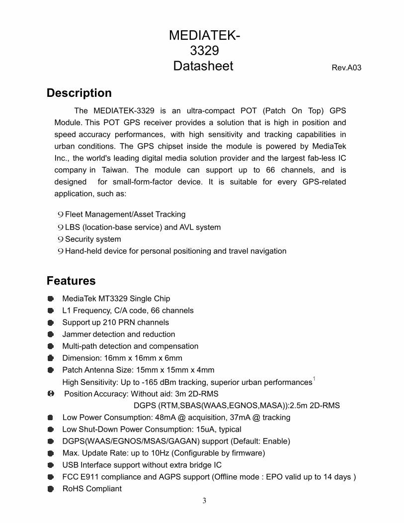
Description
The MEDIATEK-3329 is an ultra-compact POT (Patch On Top) GPS
Module. This POT GPS receiver provides a solution that is high in position and
speed accuracy performances, with high sensitivity and tracking capabilities in
urban conditions. The GPS chipset inside the module is powered by MediaTek
Inc., the world's leading digital media solution provider and the largest fab-less IC
company in Taiwan. The module can support up to 66 channels, and is
designed for small-form-factor device. It is suitable for every GPS-related
application, such as:
Fleet Management/Asset Tracking
LBS (location-base service) and AVL system
Security system
Hand-held device for personal positioning and travel navigation
Features
MediaTek MT3329 Single Chip
L1 Frequency, C/A code, 66 channels
Support up 210 PRN channels
Jammer detection and reduction
Multi-path detection and compensation
Dimension: 16mm x 16mm x 6mm
Patch Antenna Size: 15mm x 15mm x 4mm
High Sensitivity: Up to -165 dBm tracking, superior urban performances1
Position Accuracy: Without aid: 3m 2D-RMS
DGPS (RTM,SBAS(WAAS,EGNOS,MASA)):2.5m 2D-RMS
Low Power Consumption: 48mA @ acquisition, 37mA @ tracking
Low Shut-Down Power Consumption: 15uA, typical
DGPS(WAAS/EGNOS/MSAS/GAGAN) support (Default: Enable)
Max. Update Rate: up to 10Hz (Configurable by firmware)
USB Interface support without extra bridge IC
FCC E911 compliance and AGPS support (Offline mode : EPO valid up to 14 days )
RoHS Compliant
3

System Block
MEDIATEK-3329 Datasheet Rev.A03
4

Mechanical
MEDIATEK-3329 Datasheet Rev.A03
Unit: mm
5

MEDIATEK-3329
Datasheet Rev.A03
Recommend PCB Layout Pad
Footprint Top View No traces and vias are allowed to pass the area
1.2
PCB Bottom View
Unit: mm
6

Pin Configuration
MEDIATEK-3329 Datasheet Rev.A03
Pin Definition
Top View
Pin Name I/O Description
1 VCC PI Main DC power input
2 ENABLE I High active, or keep floating for normal working
3 GND P Ground
4 VBACKUP PI Backup power input
5 3D-FIX O 3D-fix indicator
6 DPLUS I/O USB port D+
7 DMINUS I/O USB port D-
8 GND P Ground
9 TXD O Serial data output of NMEA
10 RXD I Serial data input for firmware update
7

MEDIATEK-3329
Datasheet Rev.A03
Description of I/O Pin
VCC (Pin1)
The main DC power supply of the module, the voltage should be kept between from 3.2V
to 5.0V. The Vcc ripple must be controlled under 50mVpp (Typical: 3.3V)
ENABLE (Pin2)
Keep open or pull high to Power ON. Pull low to shutdown the module.
Enable (High): 1.8V<= Venable<=VCC
Disable (Low): 0V<= Venable<=0.25V
GND (Pin3)
Ground
VBACKUP (Pin4)
This is the power for GPS chipset to keep RTC running when main power is removed. The
voltage should be kept between 2.0V~4.3V. (Typical: 3.0V)
The pin must be connected for normal operation.
3D-FIX (Pin5)
The 3D-FIX was assigned as fix flag output. If not used, keep floating.
Before 2D Fix
The pin should continuously output one-second high-level with one-second
low-level signal.
1s
1s
After 2D or 3D Fix
The pin should continuously output low-level signal.
Low
8

DPLUS (Pin6)
USB Port DPLUS Signal
DMINUS (Pin7)
USB Port DMINUS Signal
GND (Pin8)
Ground
MEDIATEK-3329 Datasheet Rev.A03
TXD (Pin9)
This is the UART transmitter of the module. It outputs the GPS information for application.
RXD (Pin10)
This is the UART receiver of the module. It is used to receive software commands and
firmware update.
9

\
Reference Design
USB Interface
MEDIATEK-3329 Datasheet Rev.A03
UART Interface
10

Specifications
MEDIATEK-3329 Datasheet Rev.A03
General
Chipset MTK MT3329
Frequency L1, 1575.42MHz
C/A Code 1.023 MHz
Channels 66 channels
SBAS WAAS, EGNOS,MSAS ,GAGAN Supported(Default: Enable)
Datum WGS84(Default), Tokyo-M, Tokyo-A, User Define
CPU ARM7EJ-S
Dimensions
Length/Width/Height 16*16*6 mm
Weight 6g
Performance Characteristics
Position AccuracyWithout aid: 3m 2D-RMS
DGPS(RTM,SBAS(WAAS,EGNOS,MASA)):2.5m 2D-RMS
Velocity AccuracyWithout aid:0.1 m/s
DGPS (RTCM, SBAS ):0.05m/s
Acceleration AccuracyWithout aid:0.1 m/s²
DGPS (RTCM, SBAS ):0.05m/s²
Timing Accuracy 100 ns RMS
Sensitivity1
Acquisition:-148dBm (Cold Start)
Reacquisition:-160dBm
Tracking:-165dBm
Update Rate 1Hz (Default)
Acquisition (Open sky, stationary)
Reacquisition Time1 Less than 1 second
Hot start1 1.0s (Typical)
Warm start1 34s (Typical)
Cold start1 35s (Typical)
1 Reference to GPS chipset specification
11

MEDIATEK-3329
Datasheet Rev.A03
Dynamic
Altitude Maximum 18,000m
Velocity Maximum 515m/s
Acceleration Maximum 4G
I/O
Signal Output 8 data bits, no parity, 1 stop bit
Available Baud Rates
Default:9600bps
(4800/9600/38400/57600/115200 bps by customization)
ProtocolsNMEA 0183 v3.01 (Default: GGA,GSA,GSV,RMC,VTG)
MTK NMEA Command
Data output Interface
USB Interface Logo certified USB 2.0 full-speed compatible
UART Interface TTL level serial port
Environment
Operating Temperature -40 °C to 85 °C
Storage Temperature -50 °C to 90 °C
Operating Humidity 5% to 95% (no condensing)
Mounting SMD Type ,10 Pin
12

DC Characteristics
MEDIATEK-3329 Datasheet Rev.A03
Parameter Condition Min. Typ. Max. Unit
Operation supply Voltage 3.2 3.3 5.0 V
Operation supply Ripple Voltage 50 mVpp
Backup Battery Voltage 2.0 3.0 4.3 V
RXA TTL H Level VCC=3.3V 2.1 2.8 V
RXA TTL L Level VCC=3.3V 0 0.9 V
TXA TTL H Level VCC=3.3V 2.1 2.8 V
TXA TTL L Level VCC=3.3V 0 0.8 V
USB D+ VCC=5.0V V
USB D- VCC=5.0V V
Power Consumption @ 3.3VAcquisition 43 48 53 mA
Tracking 32 37 42 mA
Backup Power Consumption@ 3.0V 25°C 10 uA
Shut-down Power Consumption
(via enable pin)
25°C 15 uA
NMEA Output Sentence
Table-1 lists each of the NMEA output sentences specifically developed and defined by
MTK for use within MTK products
NMEA Output Sentence Table-1
Option Description
GGA Time, position and fix type data.
GSA GPS receiver operating mode, active satellites
used in the position solution, and DOP values.
GSV The number of GPS satellites in view satellite ID
numbers, elevation, azimuth, and SNR values.
RMC Time, date, position, course and speed data.
Recommended Minimum Navigation Information.
VTG Course and speed information relative to the
ground.
13

MEDIATEK-3329
Datasheet Rev.A03
GGA—Global Positioning System Fixed Data. Time, Position and fix related data for
a GPS receiver
Table-2 contains the values for the following example:
$GPGGA,064951.000,2307.1256,N,12016.4438,E,1,8,0.95,39.9,M,17.8,M,,*65
GGA Data Format Table-2
Name Example Units Description
Message ID $GPGGA GGA protocol header
UTC Time 064951.000 hhmmss.sss
Latitude 2307.1256 ddmm.mmmm
N/S Indicator N N=north or S=south
Longitude 12016.4438 dddmm.mmmm
E/W Indicator E E=east or W=west
Position Fix
Indicator
1 See Table-3
Satellites Used 8 Range 0 to 14
HDOP 0.95 Horizontal Dilution of
Precision
MSL Altitude 39.9 meters Antenna Altitude above/below
mean-sae-level
Units M meters Units of antenna altitude
Geoidal
Separation
17.8 meters
Units M meters Units of geoidal separation
Age of Diff. Corr. second Null fields when DGPS is not
used
Checksum *65
<CR> <LF> End of message termination
Position Fix Indicator Table-3
Value Description
0 Fix not available
1 GPS fix
2 Differential GPS fix
14

MEDIATEK-3329
Datasheet Rev.A03
GSA—GNSS DOP and Active Satellites
Table-4 contains the values for the following example:
$GPGSA,A,3,29,21,26,15,18,09,06,10,,,,,2.32,0.95,2.11*00
GSA Data Format Table-4
Name Example Units Description
Message ID $GPGSA GSA protocol header
Mode 1 A See Table-5
Mode 2 3 See Table-6
Satellite Used 29 SV on Channel 1
Satellite Used 21 SV on Channel 2
.... …. …. ....
Satellite Used SV on Channel 12
PDOP 2.32 Position Dilution of Precision
HDOP 0.95 Horizontal Dilution of Precision
VDOP 2.11 Vertical Dilution of Precision
Checksum *00
<CR> <LF> End of message termination
Mode 1 Table-5
Value Description
M Manual—forced to operate in 2D or 3D mode
A 2D Automatic—allowed to automatically switch 2D/3D
Mode 2 Table-6
Value Description
1 Fix not available
2 2D ( 4 SVs used)
3 3D ( 4 SVs used)
15

MEDIATEK-3329
Datasheet Rev.A03
GSV—GNSS Satellites in View
Table-7 contains the values for the following example:
$GPGSV,3,1,09,29,36,029,42,21,46,314,43,26,44,020,43,15,21,321,39*7D
$GPGSV,3,2,09,18,26,314,40,09,57,170,44,06,20,229,37,10,26,084,37*77
$GPGSV,3,3,09,07,,,26*73
GSV Data Format Table-7
Name Example Units Description
Message ID $GPGSV GSV protocol header
Number of
Messages
3 Range 1 to 3
(Depending on the number of
satellites tracked, multiple
messages of GSV data may be
required.)
Message Number1 1 Range 1 to 3
Satellites in View 09
Satellite ID 29 Channel 1 (Range 1 to 32)
Elevation 36 degrees Channel 1 (Maximum 90)
Azimuth 029 degrees Channel 1 (True, Range 0 to
359)
SNR (C/No) 42 dBHz Range 0 to 99,
(null when not tracking)
.... …. …. ....
Satellite ID 15 Channel 4 (Range 1 to 32)
Elevation 21 degrees Channel 4 (Maximum 90)
Azimuth 321 degrees Channel 4 (True, Range 0 to
359)
SNR (C/No) 39 dBHz Range 0 to 99,
(null when not tracking)
Checksum *7D
<CR> <LF> End of message termination
16
MEDIATEK-3329
Datasheet Rev.A03
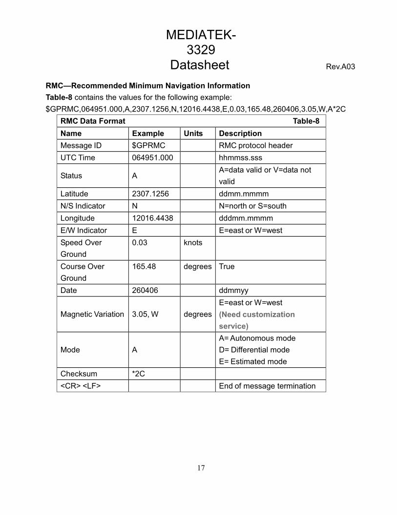
RMC—Recommended Minimum Navigation Information
Table-8 contains the values for the following example:
$GPRMC,064951.000,A,2307.1256,N,12016.4438,E,0.03,165.48,260406,3.05,W,A*2C
RMC Data Format Table-8
Name Example Units Description
Message ID $GPRMC RMC protocol header
UTC Time 064951.000 hhmmss.sss
Status AA=data valid or V=data not
valid
Latitude 2307.1256 ddmm.mmmm
N/S Indicator N N=north or S=south
Longitude 12016.4438 dddmm.mmmm
E/W Indicator E E=east or W=west
Speed Over
Ground
0.03 knots
Course Over
Ground
165.48 degrees True
Date 260406 ddmmyy
Magnetic Variation 3.05, W degrees
E=east or W=west
(Need customization
service)
Mode A
A= Autonomous mode
D= Differential mode
E= Estimated mode
Checksum *2C
<CR> <LF> End of message termination
17

MEDIATEK-3329
Datasheet Rev.A03
VTG—Course and speed information relative to the ground.
Table-9 contains the values for the following example:
$GPVTG,165.48,T,,M,0.03,N,0.06,K,A*37
VTG Data Format Table-9
Name Example Units Description
Message ID $GPVTG VTG protocol header
Course 165.48 degrees Measured heading
Reference T True
Course degrees Measured heading
Reference M Magnetic
(Need customization
service.)
Speed 0.03 knots Measured horizontal speed
Units N Knots
Speed 0.06 km/hr Measured horizontal speed
Units K Kilometers per hour
Mode A A= Autonomous mode
D= Differential mode
E= Estimated mode
Checksum *06
<CR> <LF> End of message termination
MTK NMEA Command Protocol
Packet Type:
103 PMTK_CMD_COLD_START
Packet Meaning:
Cold Start: Don’t use Time, Position, Almanacs and Ephemeris data at re-start.
Example:
$PMTK103*30<CR><LF>
18

MEDIATEK-3329
Datasheet Rev.A03
Manual Soldering:
Soldering iron:
Bit Temperature: Under 380°C Time: Under 3 sec.
Notes:
1. Please do not directly touch the soldering pads on the surface of the PCB
board, in order to prevent further oxidation
2. The solder paste must be defrosted to room temperature before use so it can
return to its optimal working temperature. The time required for this procedure
is unique and dependent on the properties of the solder paste used.
3. The steel plate must be properly assessed before and after use, so its
measurement stays strictly within the specification set by SOP.
4. Please watch out for the spacing between soldering joint, as excess solder may
cause electrical shortage
5. Please exercise with caution and do not use extensive amount of flux due to
possible siphon effects on neighboring components, which may lead to
electrical shortage.
6. Please do not use the heat gun for long periods of time when removing the
shielding or inner components of the GPS module, as it is very likely to cause a
shift to the inner components and will leads to electrical shortage.
19