Embed Size (px)
Citation preview
Operating instructions - Translation of the original -
English GBR
20.0
4.20
16
KIESELMANN GmbHPaul-Kieselmann-Str.4-10
D - 75438 Knittlingen
+49 (0) 7043 371-0Fax: +49 (0) 7043 [email protected]
1
Vacuum valve
Type: 6160DN 50 - DN 150spring loaded
20.4
.16 Vacuum valve Type: 6160
List of contents 1
1. General Information................................................................................................................ 21.1 Information for your safety ........................................................................................... 21.2 Marking of security instructions in the operating manual ............................................. 21.3 Designated use ............................................................................................................ 21.4 Personnel ..................................................................................................................... 21.5 Modifications, spare parts, accessories ....................................................................... 21.6 General instructions ..................................................................................................... 2
2. Safety informations.................................................................................................................. 32.1 Intended use ................................................................................................................ 32.2 General safety instructions .......................................................................................... 32.3 General notes .............................................................................................................. 3
3. Function and operation............................................................................................................ 43.1 Description of function ................................................................................................. 43.2 Installation instructions................................................................................................. 43.3 Welding guidelines....................................................................................................... 43.4 Service and maintenance ............................................................................................ 43.5 Technical Data ............................................................................................................. 53.6 Identification................................................................................................................. 53.7 Pressure setting ........................................................................................................... 6
4. Disassembly / Assembly ......................................................................................................... 74.1 DN 50 - DN 100 ......................................................................................................... 74.2 DN 125 - DN 150 ....................................................................................................... 8
5. Drawing and dimensions ......................................................................................................... 9
6. Spare parts list ...................................................................................................................... 11
7. Performance chart ................................................................................................................. 12
L i s t o f c o n t e n t s
20.4
.16
1. General Information 2
1 . G e n e r a l I n f o r m a t i o n
1.1 Information for your safetyWe are pleased that you have decided for a high-class KIESELMANN product. With correct application and ade-quate maintenance, our products provide long time and reliable operation.Before installation and initiation, please carefully read this instruction manual and the security advices containedin it. This guarantees reliable and safe operation of this product and your plant respectively. Please note that anincorrect application of the process components may lead to great material damages and personal injury. In case of damages caused by non observance of this instruction manual, incorrect initiation, handlingor external interference, guarantee and warranty will lapse!Our products are produced, mounted and tested with high diligence. However, if there is still a reason for com-plaint, we will naturally try to give you entire satisfaction within the scope of our warranty. We will be at yourdisposal also after expiration of the warranty. In addition, you will also find all necessary instructions and sparepart data for maintenance in this instruction manual. If you don't want to carry out the maintenance by yourself,our KIESELMANN service team will naturally be at your disposal.
1.2 Marking of security instructions in the operating manualHints are available in the chapter "safety instructions" or directly before the respective operation instruction. Thehints are highlighted with a danger symbol and a signal word. Texts beside these symbols have to be read andadhered to by all means. Please continue with the text and with the handling at the valve only afterwards.
1.3 Designated useThe fitting is designed exclusively for the purposes described below. Using the fitting for purposes other thanthose mentioned is considered contrary to its designated use. KIESELMANN cannot be held liable for any dam-age resulting from such use. The risk of such misuse lies entirely with the user. The prerequisite for the reliableand safe operation of the fitting is proper transportation and storage as well as competent installation andassembly.Operating the fitting within the limits of its designated use also involves observing the operating, inspection andmaintenance instructions.
1.4 PersonnelPersonnel entrusted with the operation and maintenance of the tank safety system must have the suitable qual-ification to carry out their tasks. They must be informed about possible dangers and must understand andobserve the safety instructions given in the relevant manual. Only allow qualified personnel to make electricalconnections.
1.5 Modifications, spare parts, accessoriesUnauthorized modifications, additions or conversions which affect the safety of the fitting are not permitted.Safety devices must not be bypassed, removed or made inactive. Only use original spare parts and accessoriesrecommended by the manufacturer.
1.6 General instructionsThe user is obliged to operate the fitting only when it is in good working order. In addition to the instructionsgiven in the operating manual, please observe the relevant accident prevention regulations, generally acceptedsafety regulations, regulations effective in the country of installation, working and safety instructions effective inthe user's plant.
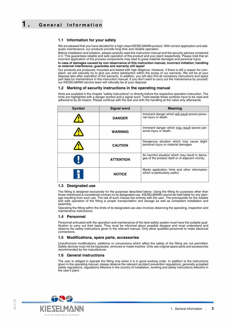
Symbol Signal word Meaning
DANGERImminent danger which will result severe perso-nal injury or death.
WARNINGImminent danger which may result severe per-sonal injury or death.
CAUTIONDangerous situation which may cause slightpersonal injury or material damages.
ATTENTIONAn harmful situation which may result in dama-ges of the product itself or of adjacent vicinity.
NOTICEMarks application hints and other informationwhich is particularly useful.
20.4
.16
2 . S a f e t y i n f o r m a t i o n s
2 . 1 Intended use
This vacuum valve is used to prevent underpressures in tanks and vessels for food and beverageindustry, pharmaceutical and chemical industries as well as in biotechnology.
2 . 2 General safety instructions
2 . 3 General notes
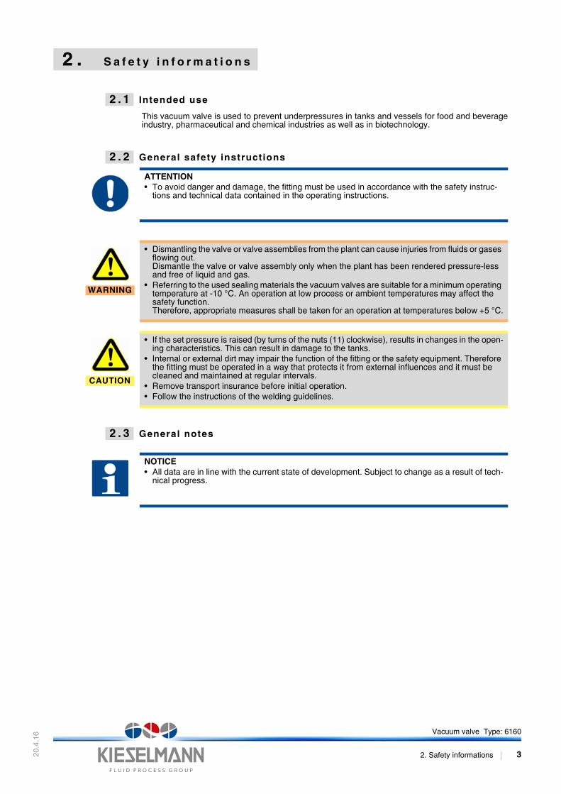
ATTENTION• To avoid danger and damage, the fitting must be used in accordance with the safety instruc-
tions and technical data contained in the operating instructions.
WARNING
• Dismantling the valve or valve assemblies from the plant can cause injuries from fluids or gases flowing out.Dismantle the valve or valve assembly only when the plant has been rendered pressure-less and free of liquid and gas.
• Referring to the used sealing materials the vacuum valves are suitable for a minimum operating temperature at -10 °C. An operation at low process or ambient temperatures may affect the safety function.Therefore, appropriate measures shall be taken for an operation at temperatures below +5 °C.
CAUTION
• If the set pressure is raised (by turns of the nuts (11) clockwise), results in changes in the open-ing characteristics. This can result in damage to the tanks.
• Internal or external dirt may impair the function of the fitting or the safety equipment. Therefore the fitting must be operated in a way that protects it from external influences and it must be cleaned and maintained at regular intervals.
• Remove transport insurance before initial operation.• Follow the instructions of the welding guidelines.
NOTICE• All data are in line with the current state of development. Subject to change as a result of tech-
nical progress.
Vacuum valve Type: 6160
2. Safety informations 3
20.4
.16
3 . F u n c t i o n a n d o p e r a t i o n
3 . 1 Description of function
The function of the vacuum valve is to prevent inadmissible pressure shortfalls (1bar absolutepressure), in tanks and containers, which can result in damage. At underpressure, the valve opensto the atmosphere. The pressure in the tank is brought to the atmospheric pressure by the inflowingair. When the pressures become equal, the valve closes by spring force. The flow capacitiesreferred to the relevant underpressure are shown in the capacity diagram (see “7. Performancechart” on page 12).
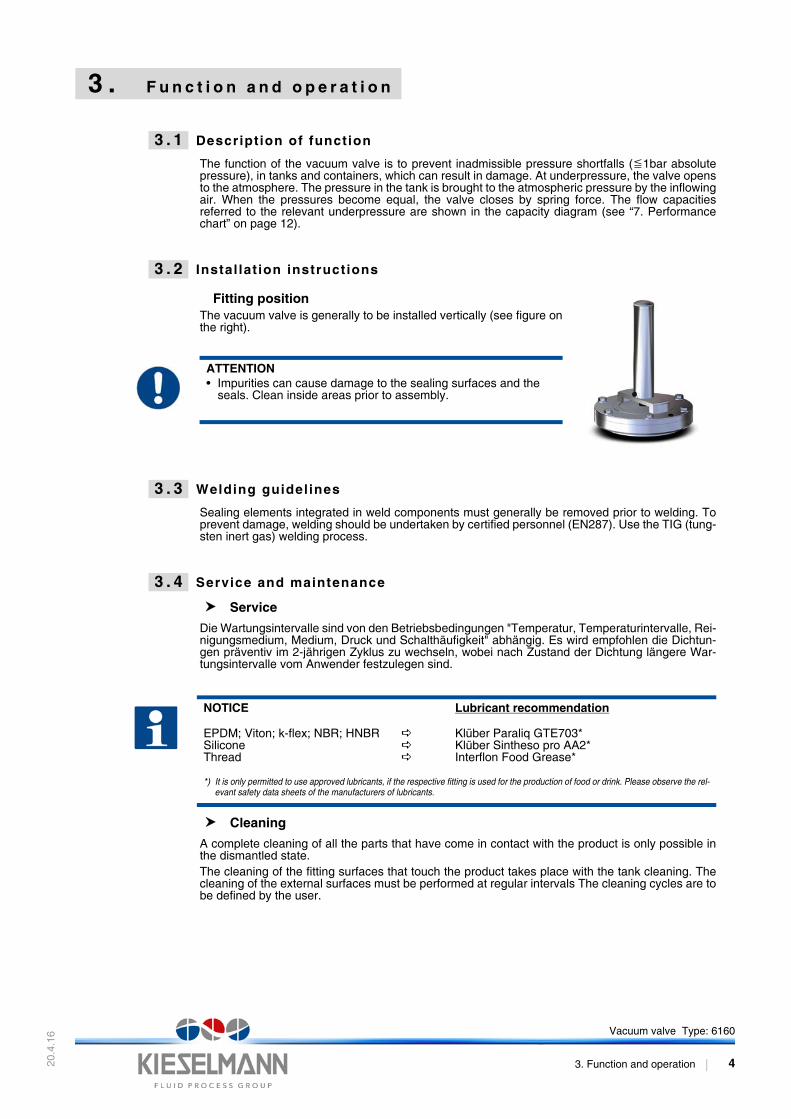
3 . 2 Instal lat ion instructions
Fitting positionThe vacuum valve is generally to be installed vertically (see figure onthe right).
3 . 3 Welding guidelines
Sealing elements integrated in weld components must generally be removed prior to welding. Toprevent damage, welding should be undertaken by certified personnel (EN287). Use the TIG (tung-sten inert gas) welding process.
3 . 4 Service and maintenance
Service
Die Wartungsintervalle sind von den Betriebsbedingungen "Temperatur, Temperaturintervalle, Rei-nigungsmedium, Medium, Druck und Schalthäufigkeit" abhängig. Es wird empfohlen die Dichtun-gen präventiv im 2-jährigen Zyklus zu wechseln, wobei nach Zustand der Dichtung längere War-tungsintervalle vom Anwender festzulegen sind.
Cleaning
A complete cleaning of all the parts that have come in contact with the product is only possible inthe dismantled state.The cleaning of the fitting surfaces that touch the product takes place with the tank cleaning. Thecleaning of the external surfaces must be performed at regular intervals The cleaning cycles are tobe defined by the user.
ATTENTION• Impurities can cause damage to the sealing surfaces and the
seals. Clean inside areas prior to assembly.
NOTICE Lubricant recommendation
EPDM; Viton; k-flex; NBR; HNBRSiliconeThread
Klüber Paraliq GTE703*Klüber Sintheso pro AA2*Interflon Food Grease*
*) It is only permitted to use approved lubricants, if the respective fitting is used for the production of food or drink. Please observe the rel-evant safety data sheets of the manufacturers of lubricants.
Vacuum valve Type: 6160
3. Function and operation 4
20.4
.16
3 . 5 Technical Data
3 . 6 Identif icat ion
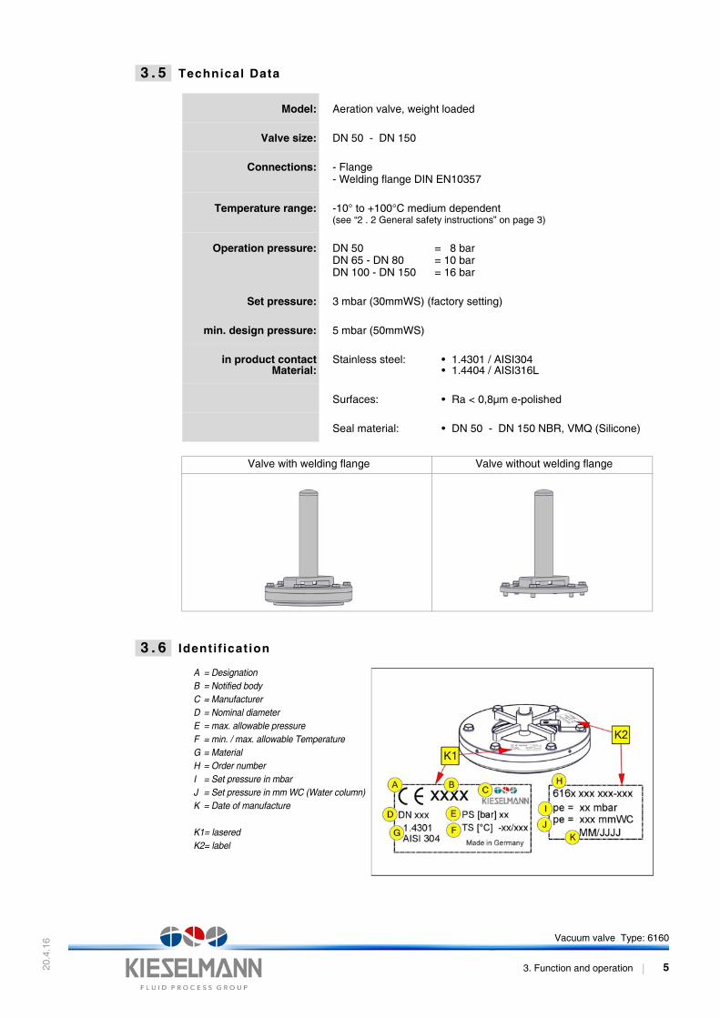
Model: Aeration valve, weight loaded
Valve size: DN 50 - DN 150
Connections: - Flange- Welding flange DIN EN10357
Temperature range: -10° to +100°C medium dependent(see “2 . 2 General safety instructions” on page 3)
Operation pressure: DN 50DN 65 - DN 80DN 100 - DN 150
= 8 bar= 10 bar= 16 bar
Set pressure: 3 mbar (30mmWS) (factory setting)
min. design pressure: 5 mbar (50mmWS)
in product contactMaterial:
Stainless steel: • 1.4301 / AISI304• 1.4404 / AISI316L
Surfaces: • Ra < 0,8µm e-polished
Seal material: • DN 50 - DN 150 NBR, VMQ (Silicone)
Valve with welding flange Valve without welding flange
A = DesignationB = Notified bodyC = ManufacturerD = Nominal diameter E = max. allowable pressureF = min. / max. allowable TemperatureG = MaterialH = Order numberI = Set pressure in mbarJ = Set pressure in mm WC (Water column)K = Date of manufacture
K1= laseredK2= label
Vacuum valve Type: 6160
3. Function and operation 5
20.4
.16
3 . 7 Pressure sett ing
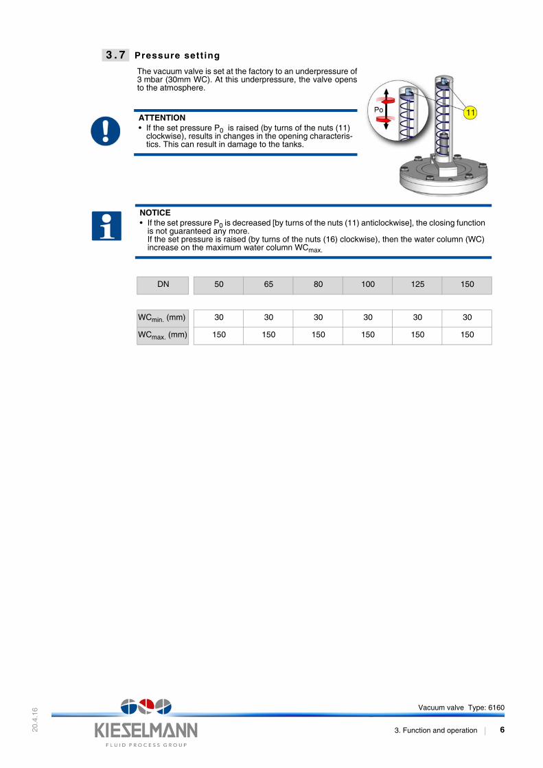
The vacuum valve is set at the factory to an underpressure of3 mbar (30mm WC). At this underpressure, the valve opensto the atmosphere.
ATTENTION• If the set pressure P0 is raised (by turns of the nuts (11)
clockwise), results in changes in the opening characteris-tics. This can result in damage to the tanks.
NOTICE• If the set pressure P0 is decreased [by turns of the nuts (11) anticlockwise], the closing function
is not guaranteed any more.If the set pressure is raised (by turns of the nuts (16) clockwise), then the water column (WC) increase on the maximum water column WCmax.
DN 50 65 80 100 125 150
WCmin. (mm) 30 30 30 30 30 30
WCmax. (mm) 150 150 150 150 150 150
Vacuum valve Type: 6160
3. Function and operation 6
20.4
.16
4 . D i s a s s e m b l y / A s s e m b l y
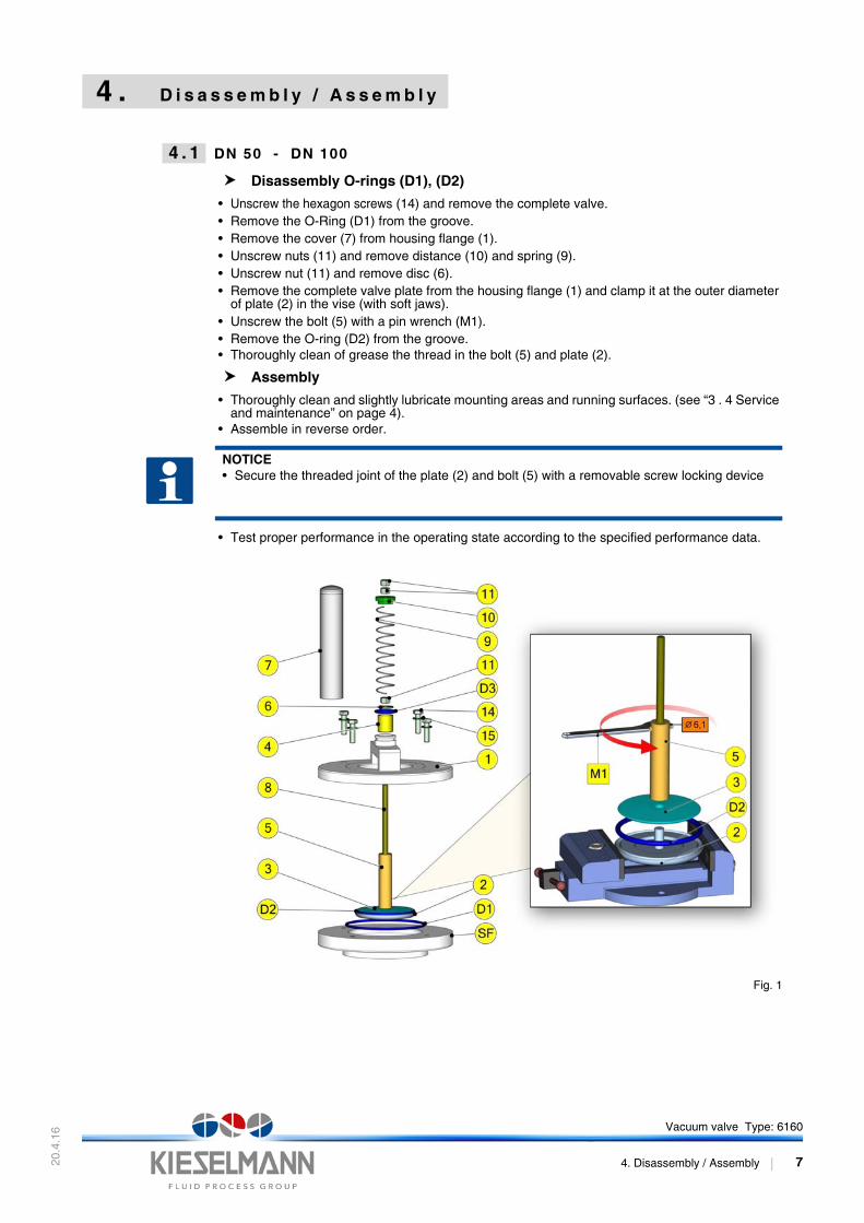
4 . 1 DN 50 - DN 100
Disassembly O-rings (D1), (D2)
• Unscrew the hexagon screws (14) and remove the complete valve.• Remove the O-Ring (D1) from the groove.• Remove the cover (7) from housing flange (1).• Unscrew nuts (11) and remove distance (10) and spring (9).• Unscrew nut (11) and remove disc (6).• Remove the complete valve plate from the housing flange (1) and clamp it at the outer diameter
of plate (2) in the vise (with soft jaws).• Unscrew the bolt (5) with a pin wrench (M1).• Remove the O-ring (D2) from the groove.• Thoroughly clean of grease the thread in the bolt (5) and plate (2).
Assembly
• Thoroughly clean and slightly lubricate mounting areas and running surfaces. (see “3 . 4 Service and maintenance” on page 4).
• Assemble in reverse order.
• Test proper performance in the operating state according to the specified performance data.
Fig. 1
NOTICE• Secure the threaded joint of the plate (2) and bolt (5) with a removable screw locking device
Vacuum valve Type: 6160
4. Disassembly / Assembly 7
20.4
.16
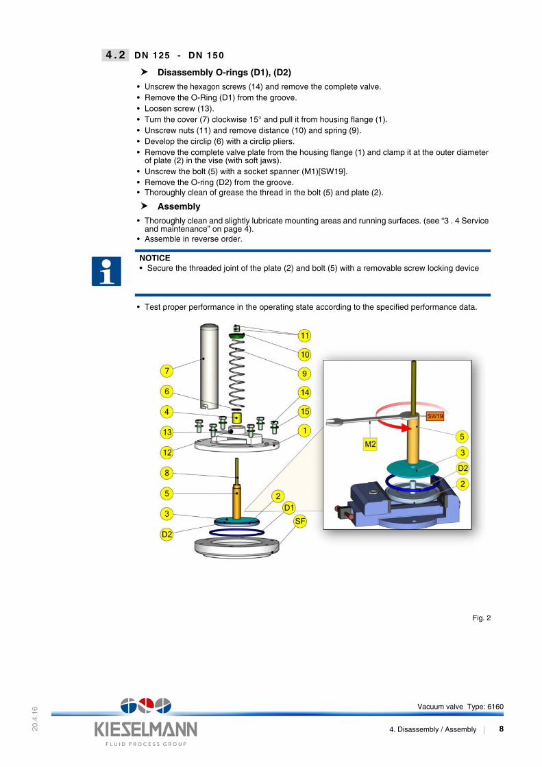
4 . 2 DN 125 - DN 150
Disassembly O-rings (D1), (D2)
• Unscrew the hexagon screws (14) and remove the complete valve.• Remove the O-Ring (D1) from the groove.• Loosen screw (13).• Turn the cover (7) clockwise 15° and pull it from housing flange (1).• Unscrew nuts (11) and remove distance (10) and spring (9).• Develop the circlip (6) with a circlip pliers.• Remove the complete valve plate from the housing flange (1) and clamp it at the outer diameter
of plate (2) in the vise (with soft jaws).• Unscrew the bolt (5) with a socket spanner (M1)[SW19].• Remove the O-ring (D2) from the groove.• Thoroughly clean of grease the thread in the bolt (5) and plate (2).
Assembly
• Thoroughly clean and slightly lubricate mounting areas and running surfaces. (see “3 . 4 Service and maintenance” on page 4).
• Assemble in reverse order.
• Test proper performance in the operating state according to the specified performance data.
Fig. 2
NOTICE• Secure the threaded joint of the plate (2) and bolt (5) with a removable screw locking device
Vacuum valve Type: 6160
4. Disassembly / Assembly 8
20.4
.16
5 . D r a w i n g a n d d i m e n s i o n s
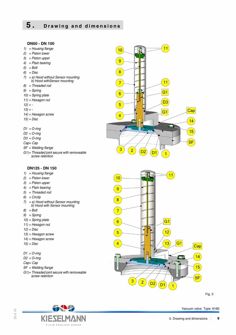
DN50 - DN 1001) = Housing flange2) = Piston lower3) = Piston upper4) = Plain bearing5) = Bolt6) = Disc7) = a) Hood without Sensor mounting
b) Hood withSensor mounting8) = Threaded rod 9) = Spring10) = Spring plate11) = Hexagon nut12) = -13) = -14) = Hexagon screw15) = Disc
D1 = O-ringD2 = O-ringD3 = O-ringCap= CapSF = Welding flangeG1)= Threaded joint secure with removeable
screw retention
DN125 - DN 1501) = Housing flange2) = Piston lower3) = Piston upper4) = Plain bearing5) = Threaded rod 6) = Circlip7) = a) Hood without Sensor mounting
b) Hood with Sensor mounting8) = Bolt9) = Spring10) = Spring plate11) = Hexagon nut12) = Disc13) = Hexagon screw14) = Hexagon screw15) = Disc
D1 = O-ringD2 = O-ringCap= CapSF = Welding flangeG1)= Threaded joint secure with removeable
screw retention
Fig. 3
Vacuum valve Type: 6160
5. Drawing and dimensions 9
20.4
.16
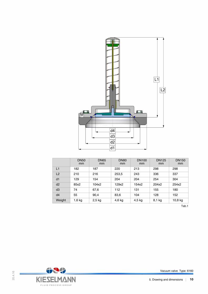
Tab.1
DN50mm
DN65mm
DN80mm
DN100mm
DN125mm
DN150mm
L1 182 187 220 213 298 298
L2 210 216 253,5 243 336 337
d1 129 154 204 204 254 304
d2 85x2 104x2 129x2 154x2 204x2 254x2
d3 74 67,6 112 131 155 180
d4 55 90,4 83,6 104 128 152
Weight 1,6 kg 2,5 kg 4,6 kg 4,5 kg 8,1 kg 10,8 kg
Vacuum valve Type: 6160
5. Drawing and dimensions 10
20.4
.16
22
21
21
20
52
55
20
00
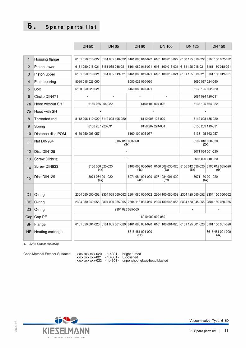
6 . S p a r e p a r t s l i s t
DN 50 DN 65 DN 80 DN 100 DN 125 DN 150
1 Housing flange 6161 050 010-022 6161 065 010-022 6161 080 010-022 6161 100 010-022 6160 125 010-022 6160 150 002-0
2 Piston lower 6161 050 018-021 6161 065 018-021 6161 080 018-021 6161 100 018-021 6161 125 018-021 6161 150 018-0
3 Piston upper 6161 050 019-021 6161 065 019-021 6161 080 019-021 6161 100 019-021 6161 125 019-021 6161 150 019-0
4 Plain bearing 8050 015 025-060 8050 023 020-060 8050 027 024-060
5 Bolt 6160 050 020-021 6160 080 020-021 6138 125 662-220
6 Circlip DIN471 - - - - 8084 024 120-031
7a Hood without SH1 6160 065 004-022 6160 100 004-022 6138 125 664-022
7b Hood with SH - - -
8 Threaded rod 8112 006 110-020 8112 008 105-020 8112 008 125-020 8112 008 185-020
9 Spring 8150 207 223-031 8150 207 224-031 8150 263 119-031
10 Distance disc POM 6160 050 005-057 6160 100 005-057 6138 125 663-057
11 Nut DIN934 8107 010 000-020(3x)
8107 010 000-020(2x)
12 Disc DIN125 - 8071 064 001-020
13 Screw DIN912 - 8095 006 010-020
14 Screw DIN933 8106 006 025-020(4x)
8106 008 030-020(4x)
8106 008 030-020(6x)
8106 012 030-020(6x)
8106 012 035-0(6x)
15 Disc DIN125 8071 064 001-020(4x)
8071 084 001-020(4x)
8071 084 001-020(6x)
8071 130 001-020(6x)
D1 O-ring 2304 050 050-052 2304 065 050-052 2304 080 050-052 2304 100 050-052 2304 125 050-052 2304 150 050-0
D2 O-ring 2304 080 040-055 2304 090 035-055 2304 113 035-055 2304 130 045-055 2304 153 045-055 2304 180 050-0
D3 O-ring 2304 025 035-055 - -
Cap Cap PE 8010 000 002-060
SF Flange 6161 050 001-020 6161 065 001-020 6161 080 001-020 6161 100 001-020 6161 125 001-020 6161 150 001-0
HP Heating cartridge 8615 481 001-000(2x)
8615 481 001-0(4x)
1. SH = Sensor mounting
Code Material Exterior Surfaces: xxxx xxx xxx-020xxxx xxx xxx-021xxxx xxx xxx-022
- 1.4301 -- 1.4301 -- 1.4301 -
bright turnedE-polishedunpolished, glass-bead blasted
Vacuum valve Type: 6160
6. Spare parts list 11
20.4
.16
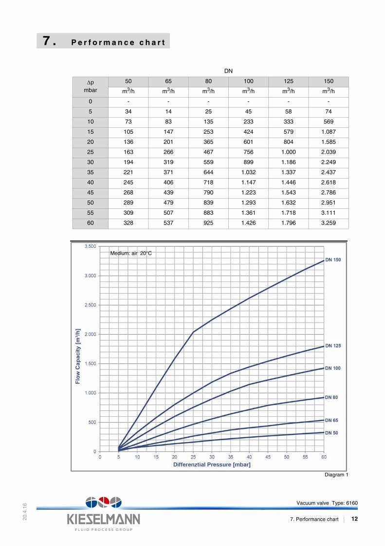
7 . P e r f o r m a n c e c h a r t
Diagram 1
DN
pmbar
50 65 80 100 125 150
m3/h m3/h m3/h m3/h m3/h m3/h
0 - - - - - -
5 34 14 25 45 58 74
10 73 83 135 233 333 569
15 105 147 253 424 579 1.087
20 136 201 365 601 804 1.585
25 163 266 467 756 1.000 2.039
30 194 319 559 899 1.186 2.249
35 221 371 644 1.032 1.337 2.437
40 245 406 718 1.147 1.446 2.618
45 268 439 790 1.223 1.543 2.786
50 289 479 839 1.293 1.632 2.951
55 309 507 883 1.361 1.718 3.111
60 328 537 925 1.426 1.796 3.259
Medium: air 20°C
Vacuum valve Type: 6160
7. Performance chart 12