Embed Size (px)
Citation preview
© 2020 SuperATV.com®. All Rights Reserved. Rev IN-LK-CA-DEF-6-001 / IN-LK-CA-DEFXMR-6 2/3/2022
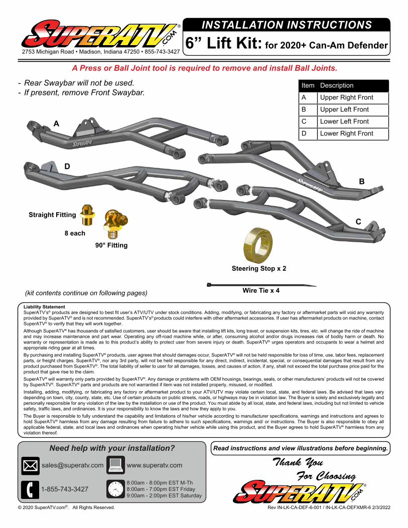
INSTALLATION INSTRUCTIONS
Item Description
A Upper Right Front
B Upper Left Front
C Lower Left Front
D Lower Right Front
6” Lift Kit: for 2020+ Can-Am Defender2753 Michigan Road • Madison, Indiana 47250 • 855-743-3427
Thank You For Choosing
Need help with your installation?
www.superatv.com
8:00am - 8:00pm EST M-Th8:00am - 7:00pm EST Friday9:00am - 2:00pm EST Saturday
1-855-743-3427
Read instructions and view illustrations before beginning.
(kit contents continue on following pages)
- Rear Swaybar will not be used.- If present, remove Front Swaybar.
A Press or Ball Joint tool is required to remove and install Ball Joints.
B
A
C
D
90° Fitting
Straight Fitting
8 each
Liability StatementSuperATV’s® products are designed to best fit user’s ATV/UTV under stock conditions. Adding, modifying, or fabricating any factory or aftermarket parts will void any warranty provided by SuperATV® and is not recommended. SuperATV’s® products could interfere with other aftermarket accessories. If user has aftermarket products on machine, contact SuperATV® to verify that they will work together.Although SuperATV® has thousands of satisfied customers, user should be aware that installing lift kits, long travel, or suspension kits, tires, etc. will change the ride of machine and may increase maintenance and part wear. Operating any off-road machine while, or after, consuming alcohol and/or drugs increases risk of bodily harm or death. No warranty or representation is made as to this product’s ability to protect user from severe injury or death. SuperATV® urges operators and occupants to wear a helmet and appropriate riding gear at all times.By purchasing and installing SuperATV® products, user agrees that should damages occur, SuperATV® will not be held responsible for loss of time, use, labor fees, replacement parts, or freight charges. SuperATV®, nor any 3rd party, will not be held responsible for any direct, indirect, incidental, special, or consequential damages that result from any product purchased from SuperATV®. The total liability of seller to user for all damages, losses, and causes of action, if any, shall not exceed the total purchase price paid for the product that gave rise to the claim.SuperATV® will warranty only parts provided by SuperATV®. Any damage or problems with OEM housings, bearings, seals, or other manufacturers’ products will not be covered by SuperATV®. SuperATV® parts and products are not warrantied if item was not installed properly, misused, or modified.Installing, adding, modifying, or fabricating any factory or aftermarket product to your ATV/UTV may violate certain local, state, and federal laws. Be advised that laws vary depending on town, city, county, state, etc. Use of certain products on public streets, roads, or highways may be in violation law. The Buyer is solely and exclusively legally and personally responsible for any violation of the law by the installation or use of the product. You must abide by all local, state, and federal laws, including but not limited to vehicle safety, traffic laws, and ordinances. It is your responsibility to know the laws and how they apply to you. The Buyer is responsible to fully understand the capability and limitations of his/her vehicle according to manufacturer specifications, warnings and instructions and agrees to hold SuperATV® harmless from any damage resulting from failure to adhere to such specifications, warnings and/ or instructions. The Buyer is also responsible to obey all applicable federal, state, and local laws and ordinances when operating his/her vehicle while using this product, and the Buyer agrees to hold SuperATV® harmless from any violation thereof.
Steering Stop x 2
Wire Tie x 4
2IN-LK-CA-DEF-6-001 / IN-LK-CA-DEFXMR-6
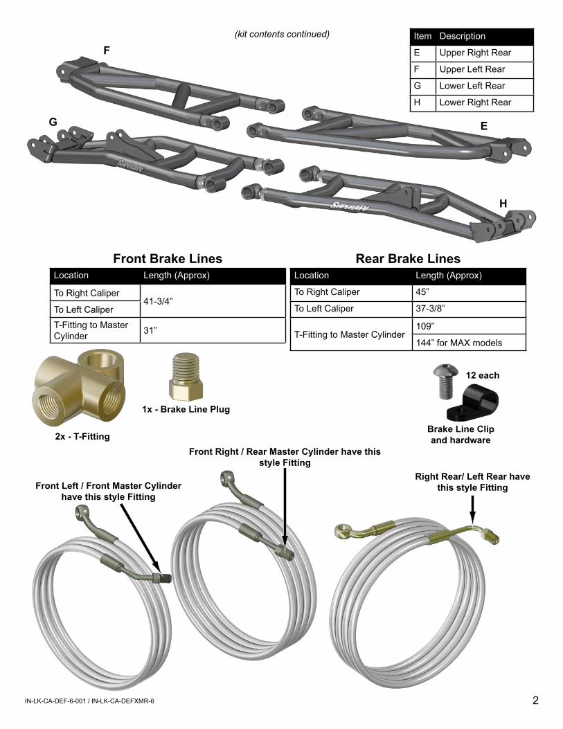
(kit contents continued) Item Description
E Upper Right Rear
F Upper Left Rear
G Lower Left Rear
H Lower Right Rear
F
E
H
G
Location Length (Approx)
To Right Caliper 45”
To Left Caliper 37-3/8”
T-Fitting to Master Cylinder109”
144” for MAX models
Rear Brake LinesLocation Length (Approx)
To Right Caliper41-3/4”
To Left CaliperT-Fitting to Master Cylinder 31”
Front Brake Lines
1x - Brake Line Plug
2x - T-FittingFront Right / Rear Master Cylinder have this
style Fitting
Front Left / Front Master Cylinder have this style Fitting
Brake Line Clip and hardware
12 each
Right Rear/ Left Rear have this style Fitting
3IN-LK-CA-DEF-6-001 / IN-LK-CA-DEFXMR-6
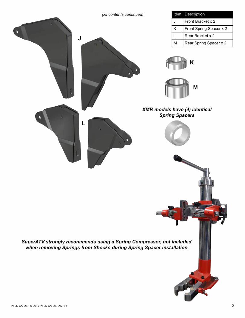
(kit contents continued) Item Description
J Front Bracket x 2
K Front Spring Spacer x 2
L Rear Bracket x 2
M Rear Spring Spacer x 2J
L
SuperATV strongly recommends using a Spring Compressor, not included, when removing Springs from Shocks during Spring Spacer installation.
K
M
XMR models have (4) identical Spring Spacers
4IN-LK-CA-DEF-6-001 / IN-LK-CA-DEFXMR-6
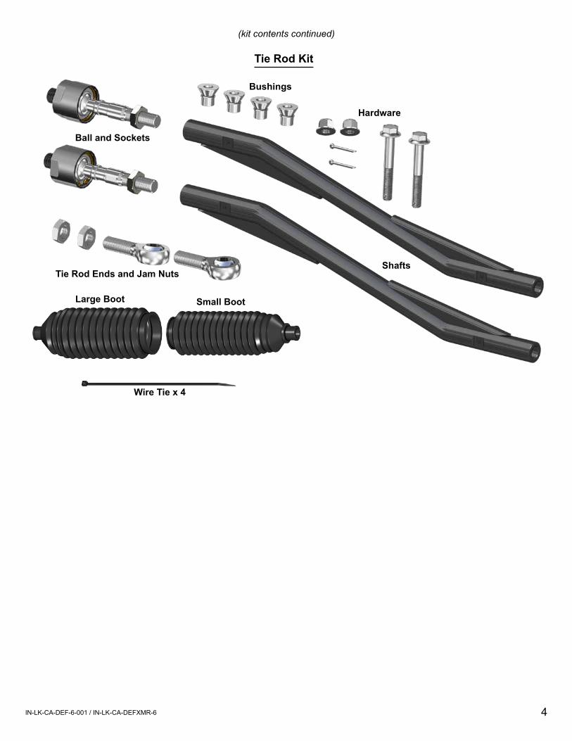
Bushings
Shafts
Ball and Sockets
Tie Rod Ends and Jam Nuts
Hardware
Tie Rod Kit
Large Boot Small Boot
Wire Tie x 4
(kit contents continued)
5IN-LK-CA-DEF-6-001 / IN-LK-CA-DEFXMR-6
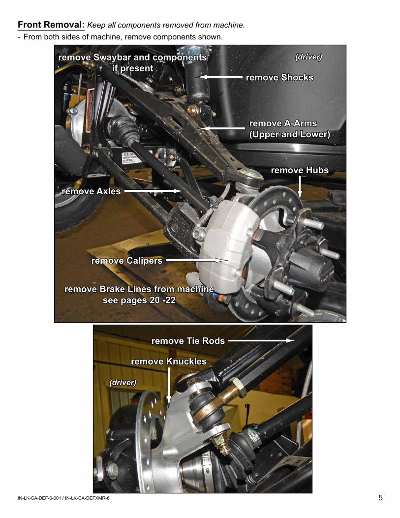
Front Removal: Keep all components removed from machine.- From both sides of machine, remove components shown.
remove A-Arms(Upper and Lower)
remove Axles
remove Brake Lines from machinesee pages 20 -22
(driver)
remove Shocks
remove Hubs
remove Calipers
remove Tie Rods
(driver)
remove Knuckles
remove Swaybar and components if present
6IN-LK-CA-DEF-6-001 / IN-LK-CA-DEFXMR-6
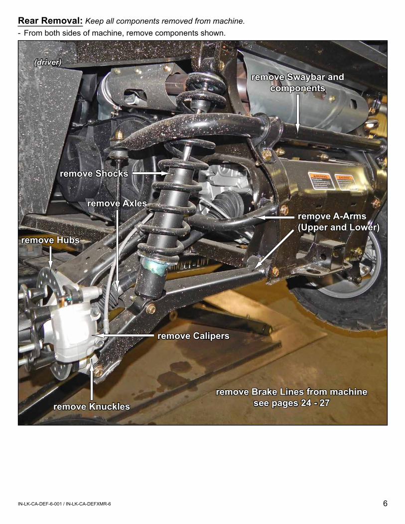
Rear Removal: Keep all components removed from machine.- From both sides of machine, remove components shown.
(driver)
remove Shocks
remove Axles
remove Swaybar and components
remove A-Arms(Upper and Lower)
remove Brake Lines from machinesee pages 24 - 27
remove Hubs
remove Calipers
remove Knuckles

7IN-LK-CA-DEF-6-001 / IN-LK-CA-DEFXMR-6
- Place Shock in Spring Compressor and remove Retainer and Spring.
- Install appropriate Spring Spacer as shown.- Reinstall Spring and Retainer.- Remove and repeat steps for remaining Shocks.- Set Shocks aside.
Spring
Retainer
(Rear Spacer (M) shown)
XMR Rear Shocks must adjust preload to highest
setting as shown
8IN-LK-CA-DEF-6-001 / IN-LK-CA-DEFXMR-6
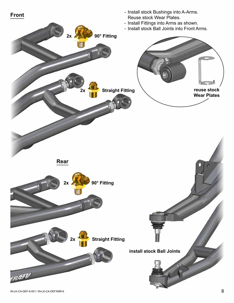
2x Straight Fitting
2x 90° Fitting
install stock Ball Joints
- Install stock Bushings into A-Arms. Reuse stock Wear Plates.
- Install Fittings into Arms as shown.- Install stock Ball Joints into Front Arms.
Front
Rear
2x Straight Fitting
2x 90° Fitting
reuse stock Wear Plates
9IN-LK-CA-DEF-6-001 / IN-LK-CA-DEFXMR-6
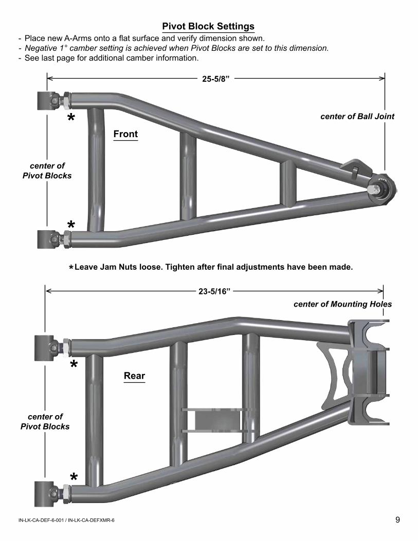
-PlacenewA-Armsontoaflatsurfaceandverifydimensionshown.- Negative 1° camber setting is achieved when Pivot Blocks are set to this dimension.- See last page for additional camber information.
center of Ball Joint*
*Leave Jam Nuts loose. Tighten after final adjustments have been made.*
center of Pivot Blocks
25-5/8”
center of Mounting Holes
*
*
center of Pivot Blocks
23-5/16”
Pivot Block Settings
Front
Rear
10IN-LK-CA-DEF-6-001 / IN-LK-CA-DEFXMR-6
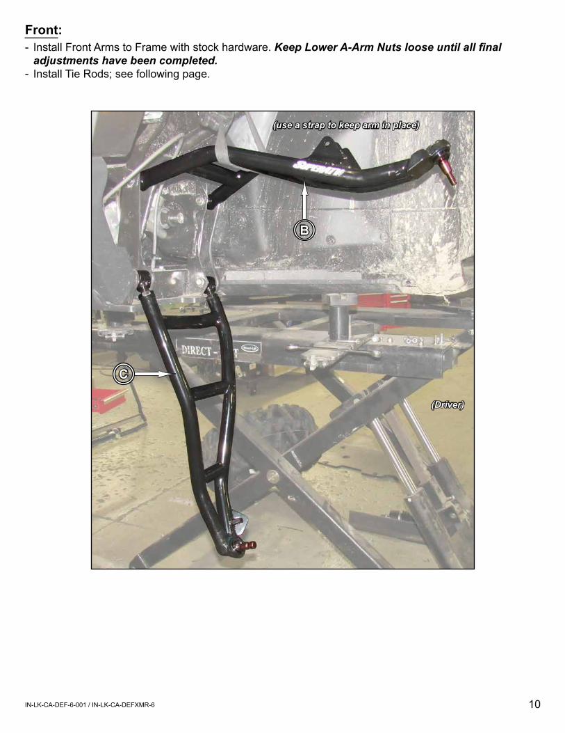
Front:- Install Front Arms to Frame with stock hardware. Keep Lower A-Arm Nuts loose until all final
adjustments have been completed.- Install Tie Rods; see following page.
B
C
(use a strap to keep arm in place)
(Driver)
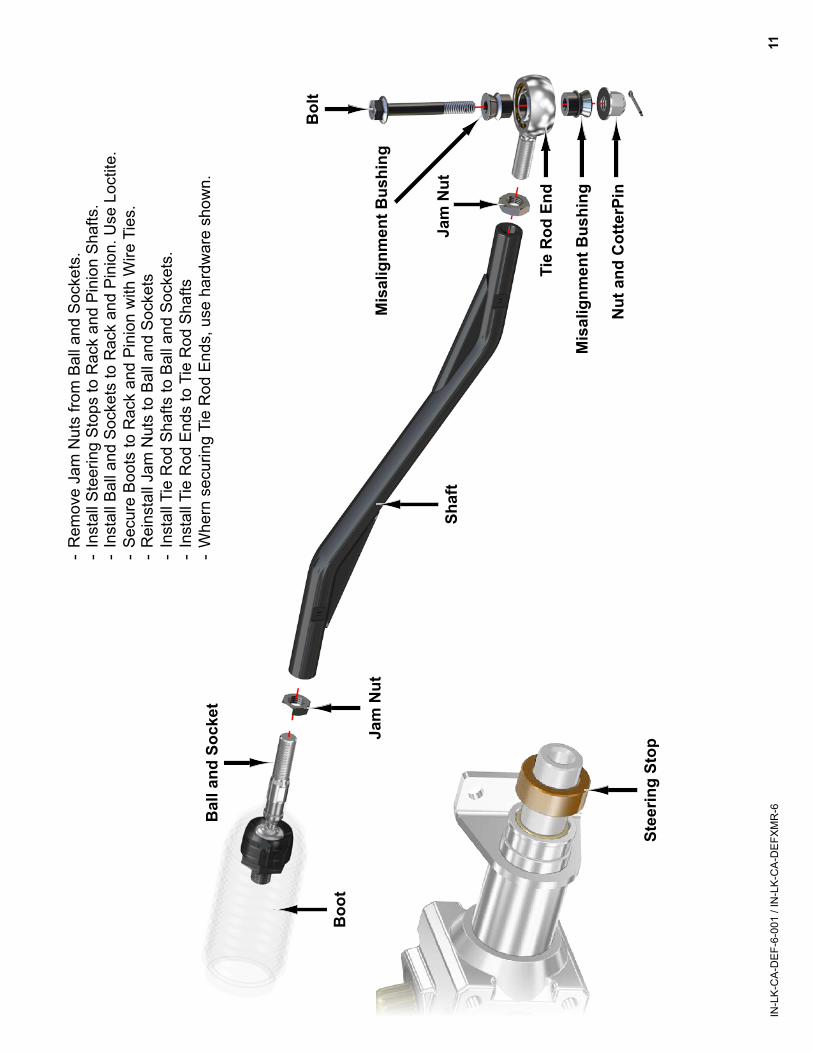
Shaf
t
Bal
l and
Soc
ket
Boo
t
Jam
Nut
Jam
Nut
Mis
alig
nmen
t Bus
hing
Mis
alig
nmen
t Bus
hing
Nut
and
Cot
terP
in
Bol
t
Tie
Rod
End
- R
emov
e Ja
m N
uts
from
Bal
l and
Soc
kets
.-
Inst
all S
teer
ing
Stop
s to
Rac
k an
d Pi
nion
Sha
fts.
- In
stal
l Bal
l and
Soc
kets
to R
ack
and
Pini
on. U
se L
octit
e.-
Secu
re B
oots
to R
ack
and
Pini
on w
ith W
ire T
ies.
- R
eins
tall
Jam
Nut
s to
Bal
l and
Soc
kets
- In
stal
l Tie
Rod
Sha
fts to
Bal
l and
Soc
kets
.-
Inst
all T
ie R
od E
nds
to T
ie R
od S
hafts
- W
hern
sec
urin
g Ti
e R
od E
nds,
use
har
dwar
e sh
own.
11IN
-LK-
CA-
DEF
-6-0
01 /
IN-L
K-C
A-D
EFXM
R-6
Stee
ring
Stop
12IN-LK-CA-DEF-6-001 / IN-LK-CA-DEFXMR-6
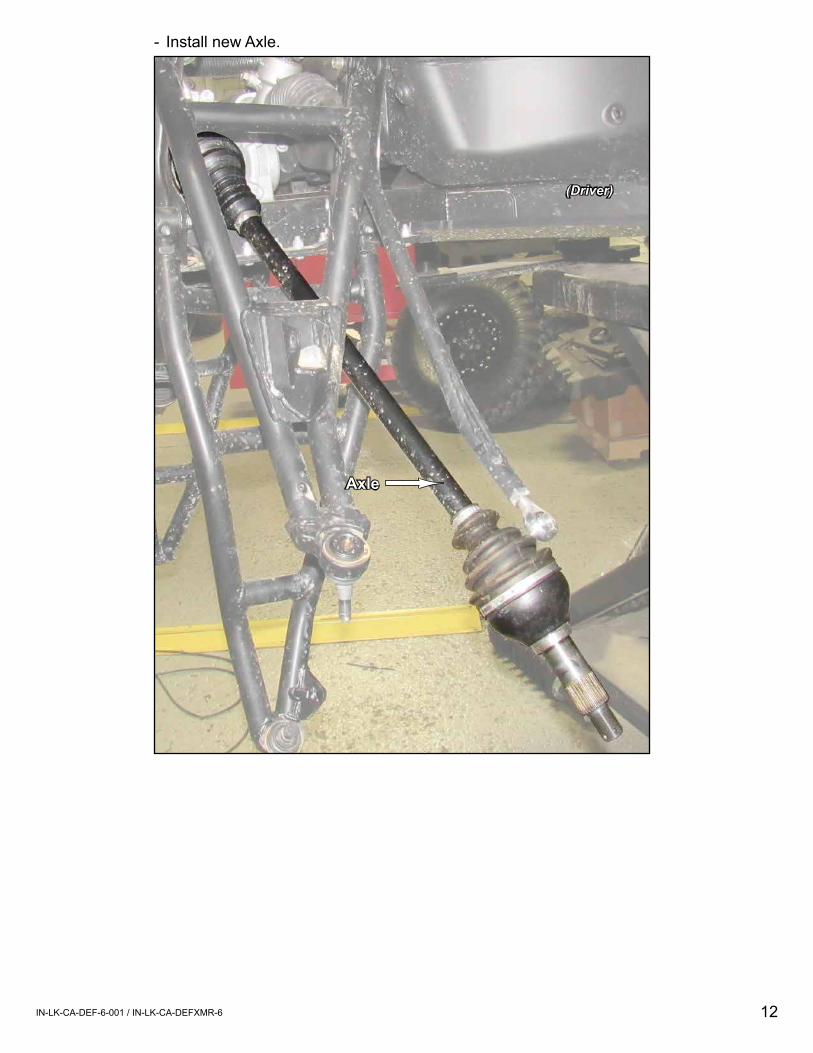
(Driver)
Axle
- Install new Axle.
13IN-LK-CA-DEF-6-001 / IN-LK-CA-DEFXMR-6
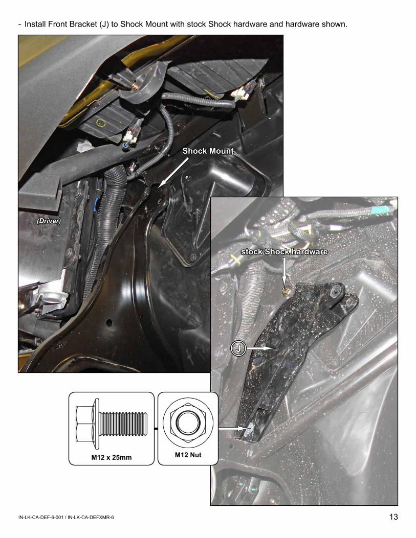
Shock Mount
(Driver)
- Install Front Bracket (J) to Shock Mount with stock Shock hardware and hardware shown.
J
stock Shock hardware
M12 NutM12 x 25mm
14IN-LK-CA-DEF-6-001 / IN-LK-CA-DEFXMR-6
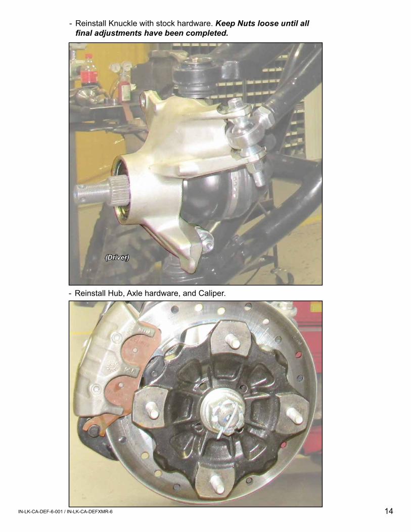
- Reinstall Hub, Axle hardware, and Caliper.
- Reinstall Knuckle with stock hardware. Keep Nuts loose until all final adjustments have been completed.
(Driver)
15IN-LK-CA-DEF-6-001 / IN-LK-CA-DEFXMR-6
(Driver)
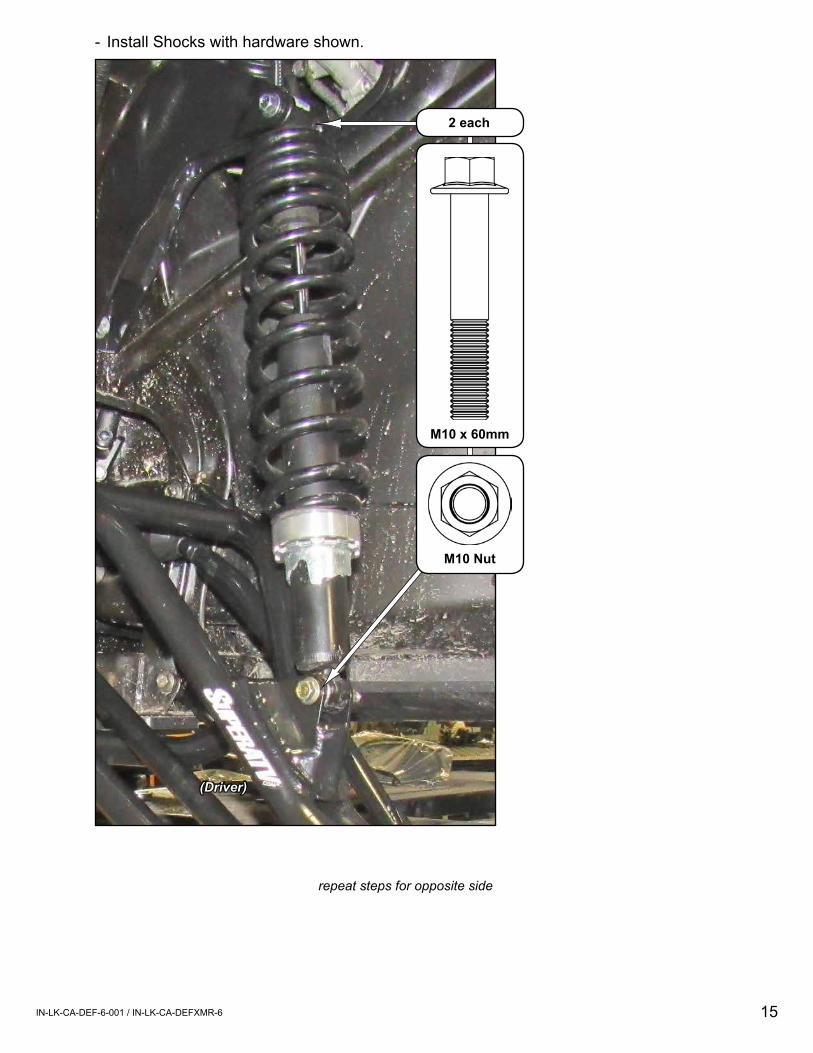
- Install Shocks with hardware shown.
2 each
M10 x 60mm
M10 Nut
repeat steps for opposite side
16IN-LK-CA-DEF-6-001 / IN-LK-CA-DEFXMR-6
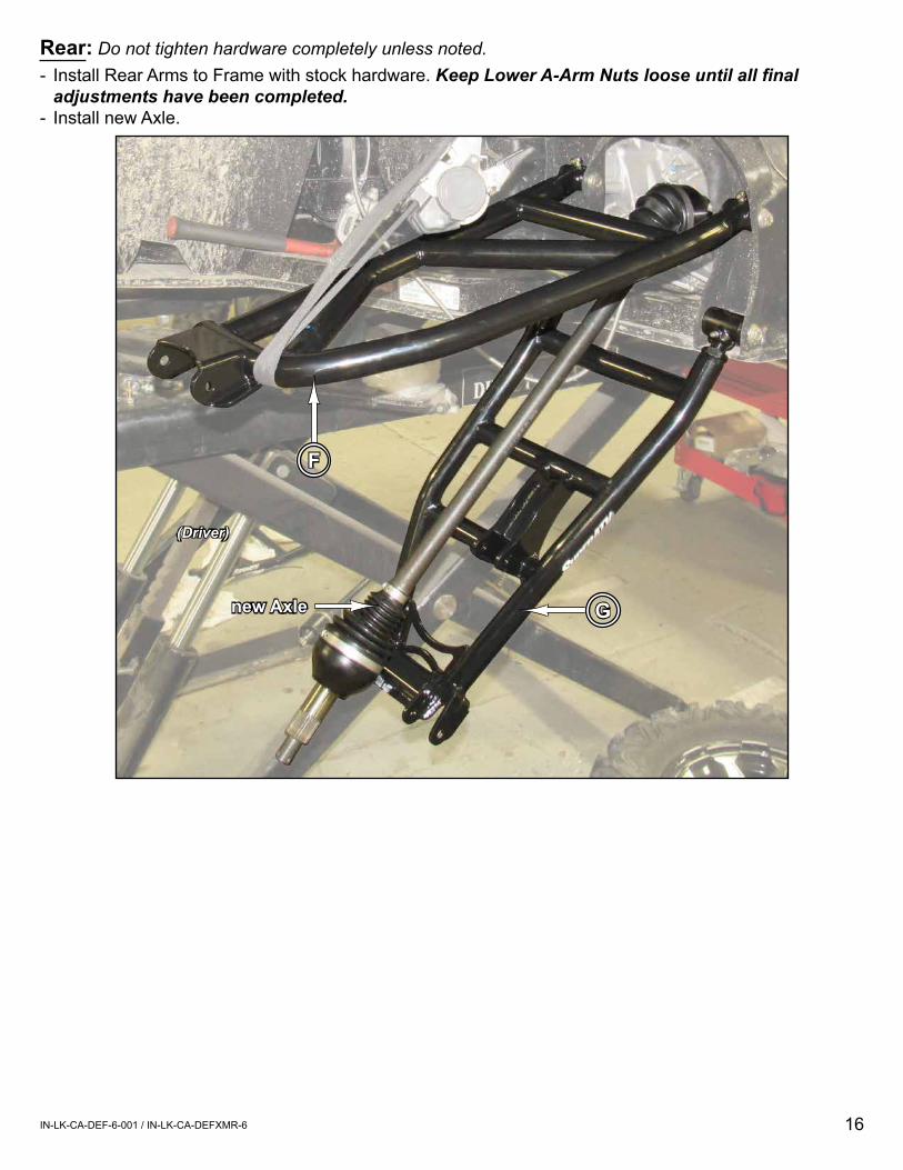
(Driver)
G
F
new Axle
Rear: Do not tighten hardware completely unless noted.- Install Rear Arms to Frame with stock hardware. Keep Lower A-Arm Nuts loose until all final
adjustments have been completed.- Install new Axle.
17IN-LK-CA-DEF-6-001 / IN-LK-CA-DEFXMR-6
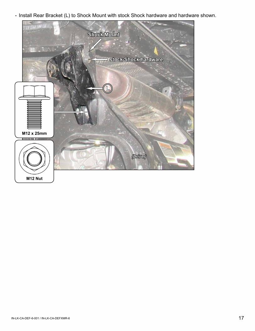
Shock Mount
stock Shock hardware
L
M12 Nut
M12 x 25mm
- Install Rear Bracket (L) to Shock Mount with stock Shock hardware and hardware shown.
(Driver)
18IN-LK-CA-DEF-6-001 / IN-LK-CA-DEFXMR-6
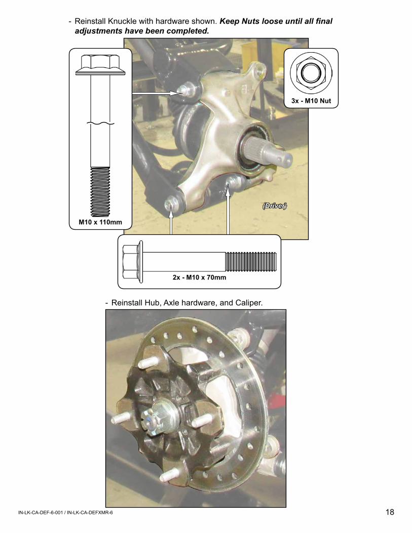
- Reinstall Hub, Axle hardware, and Caliper.
(Driver)
3x - M10 Nut
2x - M10 x 70mm
M10 x 110mm
- Reinstall Knuckle with hardware shown. Keep Nuts loose until all final adjustments have been completed.
19IN-LK-CA-DEF-6-001 / IN-LK-CA-DEFXMR-6
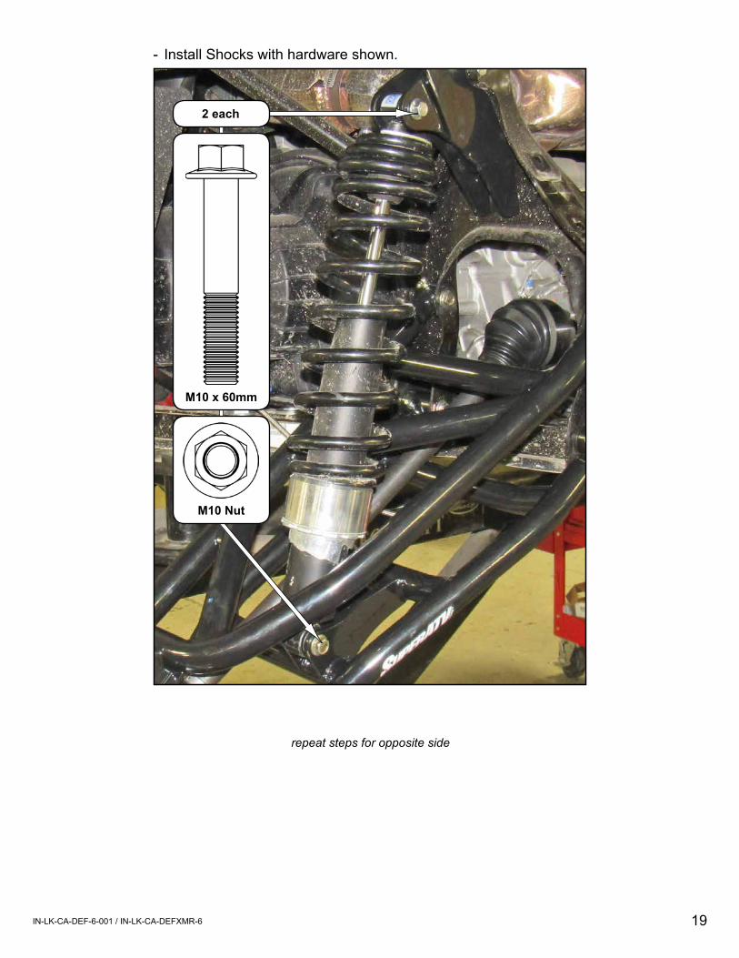
2 each
M10 x 60mm
M10 Nut
- Install Shocks with hardware shown.
repeat steps for opposite side
20IN-LK-CA-DEF-6-001 / IN-LK-CA-DEFXMR-6
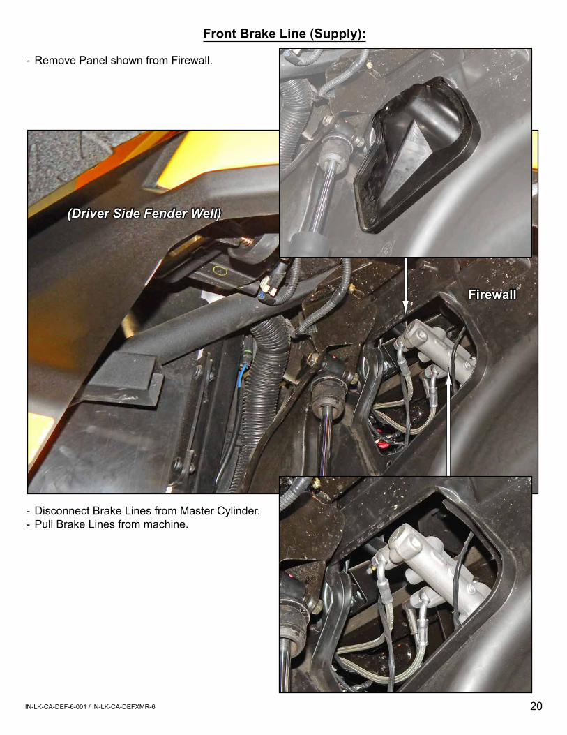
Front Brake Line (Supply):
- Remove Panel shown from Firewall.
- Disconnect Brake Lines from Master Cylinder.- Pull Brake Lines from machine.
(Driver Side Fender Well)
Firewall
21IN-LK-CA-DEF-6-001 / IN-LK-CA-DEFXMR-6
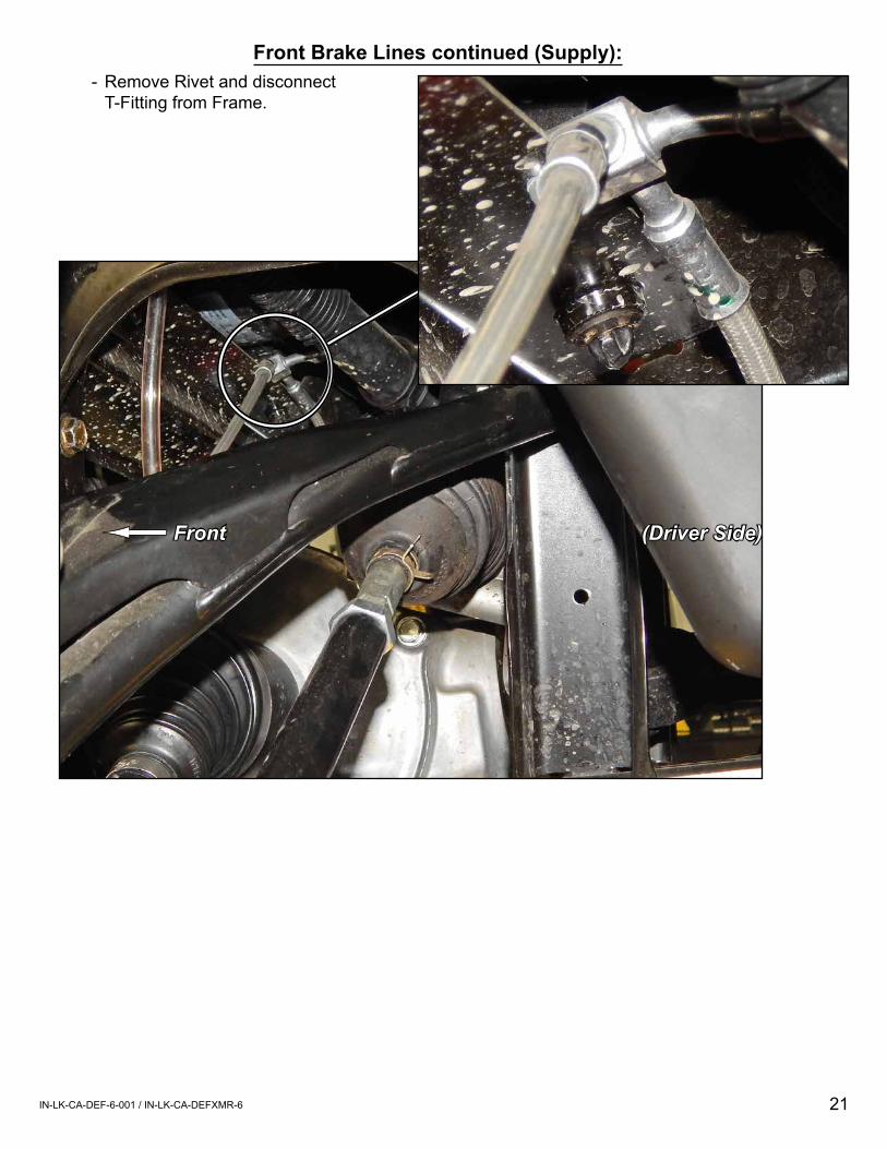
Front Brake Lines continued (Supply):
(Driver Side)
- Remove Rivet and disconnect T-Fitting from Frame.
Front
22IN-LK-CA-DEF-6-001 / IN-LK-CA-DEFXMR-6
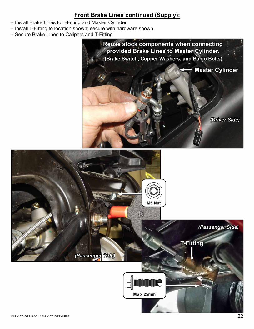
Front Brake Lines continued (Supply):- Install Brake Lines to T-Fitting and Master Cylinder.- Install T-Fitting to location shown; secure with hardware shown.- Secure Brake Lines to Calipers and T-Fitting.
(Driver Side)
Master Cylinder
Reuse stock components when connecting provided Brake Lines to Master Cylinder.
(Brake Switch, Copper Washers, and Banjo Bolts)
(Passenger Side)
T-Fitting
(Passenger Side)
M6 Nut
M6 x 25mm
23IN-LK-CA-DEF-6-001 / IN-LK-CA-DEFXMR-6
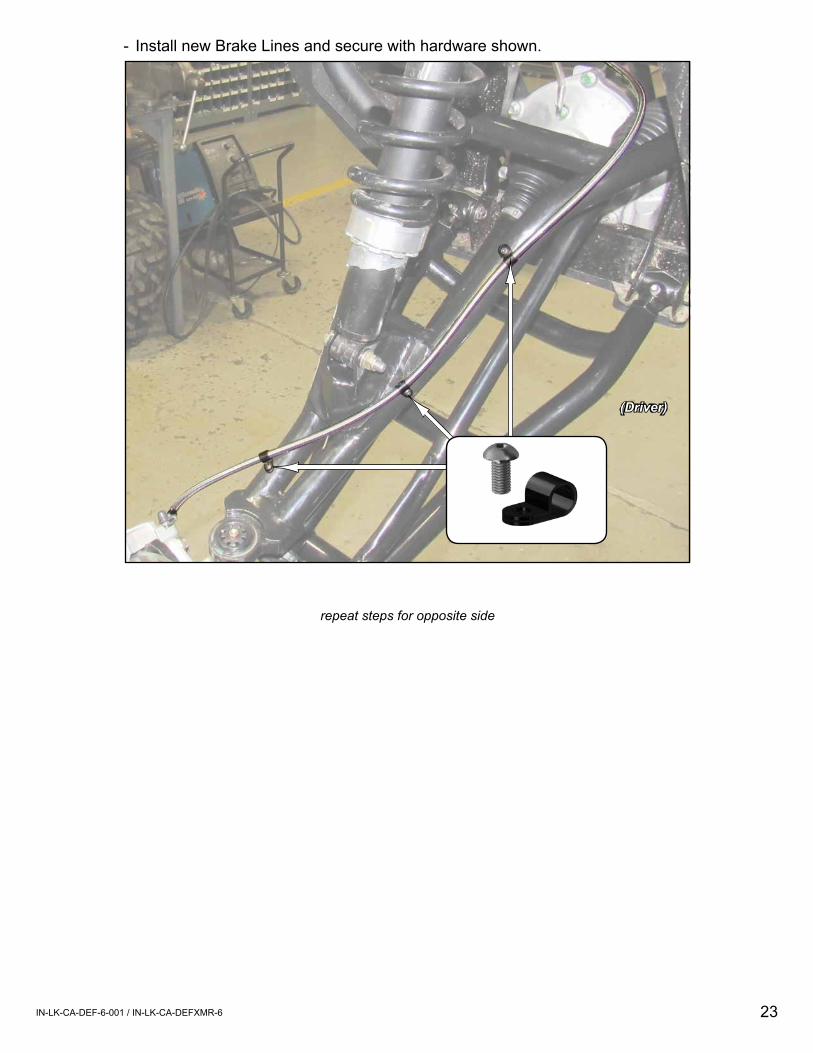
- Install new Brake Lines and secure with hardware shown.
(Driver)
repeat steps for opposite side
24IN-LK-CA-DEF-6-001 / IN-LK-CA-DEFXMR-6
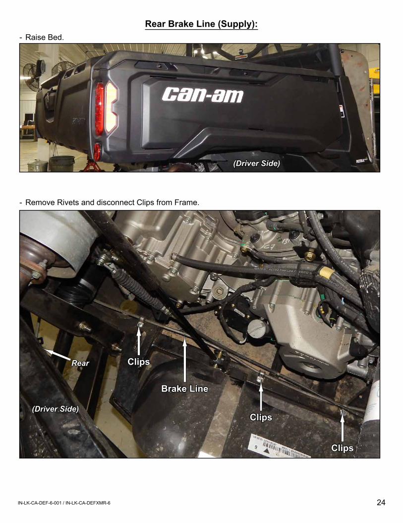
(Driver Side)
Rear Brake Line (Supply):- Raise Bed.
- Remove Rivets and disconnect Clips from Frame.
(Driver Side)
Rear
Brake Line
Clips
Clips
Clips

25IN-LK-CA-DEF-6-001 / IN-LK-CA-DEFXMR-6
(Driver Side)
- Remove Rivet and disconnect T-Fitting from Frame.Rear Brake Line (Supply) continued:
26IN-LK-CA-DEF-6-001 / IN-LK-CA-DEFXMR-6
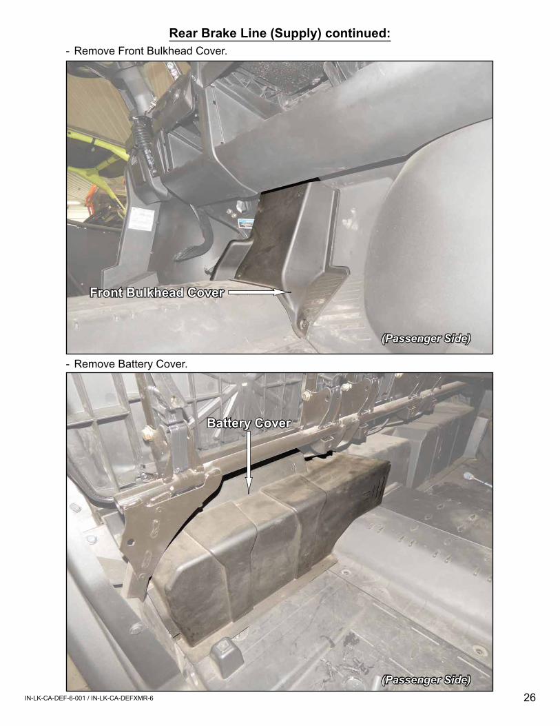
- Remove Front Bulkhead Cover.
- Remove Battery Cover.
Front Bulkhead Cover
(Passenger Side)
(Passenger Side)
Battery Cover
Rear Brake Line (Supply) continued:
27IN-LK-CA-DEF-6-001 / IN-LK-CA-DEFXMR-6
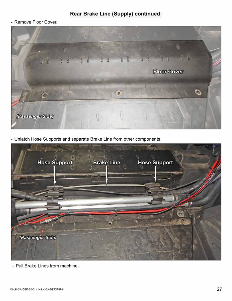
Floor Cover
Hose SupportHose Support
- Remove Floor Cover.
- Unlatch Hose Supports and separate Brake Line from other components.
(Passenger Side)
(Passenger Side)
Brake Line
- Pull Brake Lines from machine.
Rear Brake Line (Supply) continued:
28IN-LK-CA-DEF-6-001 / IN-LK-CA-DEFXMR-6
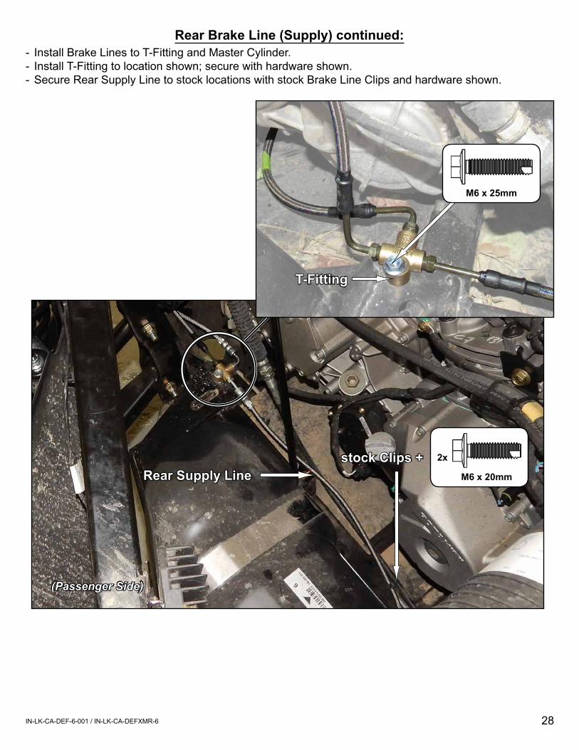
- Install Brake Lines to T-Fitting and Master Cylinder.- Install T-Fitting to location shown; secure with hardware shown.- Secure Rear Supply Line to stock locations with stock Brake Line Clips and hardware shown.
(Passenger Side)
Rear Supply Line M6 x 20mm
2xstock Clips +
Rear Brake Line (Supply) continued:
T-Fitting
M6 x 25mm
29IN-LK-CA-DEF-6-001 / IN-LK-CA-DEFXMR-6
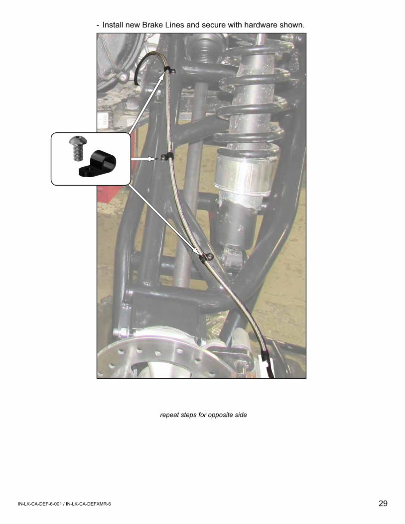
repeat steps for opposite side
- Install new Brake Lines and secure with hardware shown.
IN-Arm-Settings
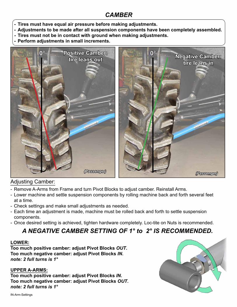
CAMBER
Negative Camber:tire leans in
Positive Camber: tire leans out
0°0°
(Passenger)(Passenger)
UPPER A-ARMS:Too much positive camber: adjust Pivot Blocks IN.Too much negative camber: adjust Pivot Blocks OUT.note: 2 full turns is 1°
LOWER:Too much positive camber: adjust Pivot Blocks OUT.Too much negative camber: adjust Pivot Blocks IN.note: 2 full turns is 1°
- Tires must have equal air pressure before making adjustments.- Adjustments to be made after all suspension components have been completely assembled. - Tires must not be in contact with ground when making adjustments.- Perform adjustments in small increments.
Adjusting Camber:- Remove A-Arms from Frame and turn Pivot Blocks to adjust camber. Reinstall Arms.- Lower machine and settle suspension components by rolling machine back and forth several feet
at a time.- Check settings and make small adjustments as needed.- Each time an adjustment is made, machine must be rolled back and forth to settle suspension
components.- Once desired setting is achieved, tighten hardware completely. Loc-tite on Nuts is recommended.
A NEGATIVE CAMBER SETTING OF 1° to 2° IS RECOMMENDED.