Embed Size (px)
Citation preview
© 2018 AT&T Intellectual Property. All rights reserved. AT&T, Globe logo, Mobilizing Your World and DIRECTV are registered trademarks and service marks of AT&T Intellectual Property
and/or AT&T affiliated companies. All other marks are the property of their respective owners.
5G NR: Optimizing RAN design architecture to support new standards
12/3/2018
Rajarajan SivarajSenior Member of Technical Staff, AT&T Labs, San Ramon, CA
Acknowledgements:
Jin Wang, Director, AT&T LabsLaurie Bigler, AVP, AT&T LabsRittwik Jana, Director, AT&T Labs ResearchDhruv Gupta, Principal Member of Technical Staff, AT&T Labs
5G NR: Optimizing Ran design architecture to support new standards
3
AGENDAIntroduction– IMT-2020 requirements for 5G
– 5G disaggregated RAN architecture for NR
– 5G Use-cases: uRLLC, eMBB, MTC
– Software Defined Networking (SDN) and Network Function Virtualization (NFV) principles for 5G
5G NR Radio Access: PHY layer enhancements– NR waveform: sub-6 GHz and mmWave
– NR frame structure: Sub-carriers and slots across frequency bands.
– Scalable TTI design and flexible slot durations in NR
– Massive MIMO, enhanced beamforming and modulation techniques
– NR signals
RAN layer enhancements for 5G NR: From MAC to RRC– Asynchronous HARQ
– MAC resource reservation, PDCP duplication and RLC windowing enhancements in 5G NR.
– Co-existence of 5G NR and 4G LTE: Multi-band aggregation, non co-located carrier aggregation, spectrum sharing
– QoS management
Summary
5G NR: Optimizing Ran design architecture to support new standards
4
INTRODUCTION
5G NR: Optimizing Ran design architecture to support new standards
5
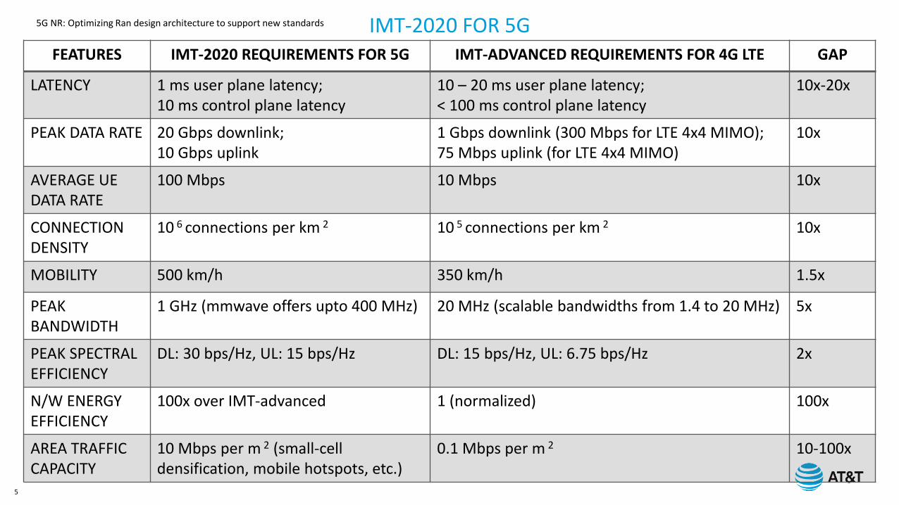
FEATURES IMT-2020 REQUIREMENTS FOR 5G IMT-ADVANCED REQUIREMENTS FOR 4G LTE GAP
LATENCY 1 ms user plane latency;10 ms control plane latency
10 – 20 ms user plane latency;< 100 ms control plane latency
10x-20x
PEAK DATA RATE 20 Gbps downlink;10 Gbps uplink
1 Gbps downlink (300 Mbps for LTE 4x4 MIMO);75 Mbps uplink (for LTE 4x4 MIMO)
10x
AVERAGE UEDATA RATE
100 Mbps 10 Mbps 10x
CONNECTION DENSITY
10 6 connections per km 2 10 5 connections per km 2 10x
MOBILITY 500 km/h 350 km/h 1.5x
PEAK BANDWIDTH
1 GHz (mmwave offers upto 400 MHz) 20 MHz (scalable bandwidths from 1.4 to 20 MHz) 5x
PEAK SPECTRAL EFFICIENCY
DL: 30 bps/Hz, UL: 15 bps/Hz DL: 15 bps/Hz, UL: 6.75 bps/Hz 2x
N/W ENERGY EFFICIENCY
100x over IMT-advanced 1 (normalized) 100x
AREA TRAFFIC CAPACITY
10 Mbps per m 2 (small-cell densification, mobile hotspots, etc.)
0.1 Mbps per m 2 10-100x
IMT-2020 FOR 5G
5G NR: Optimizing Ran design architecture to support new standards
6
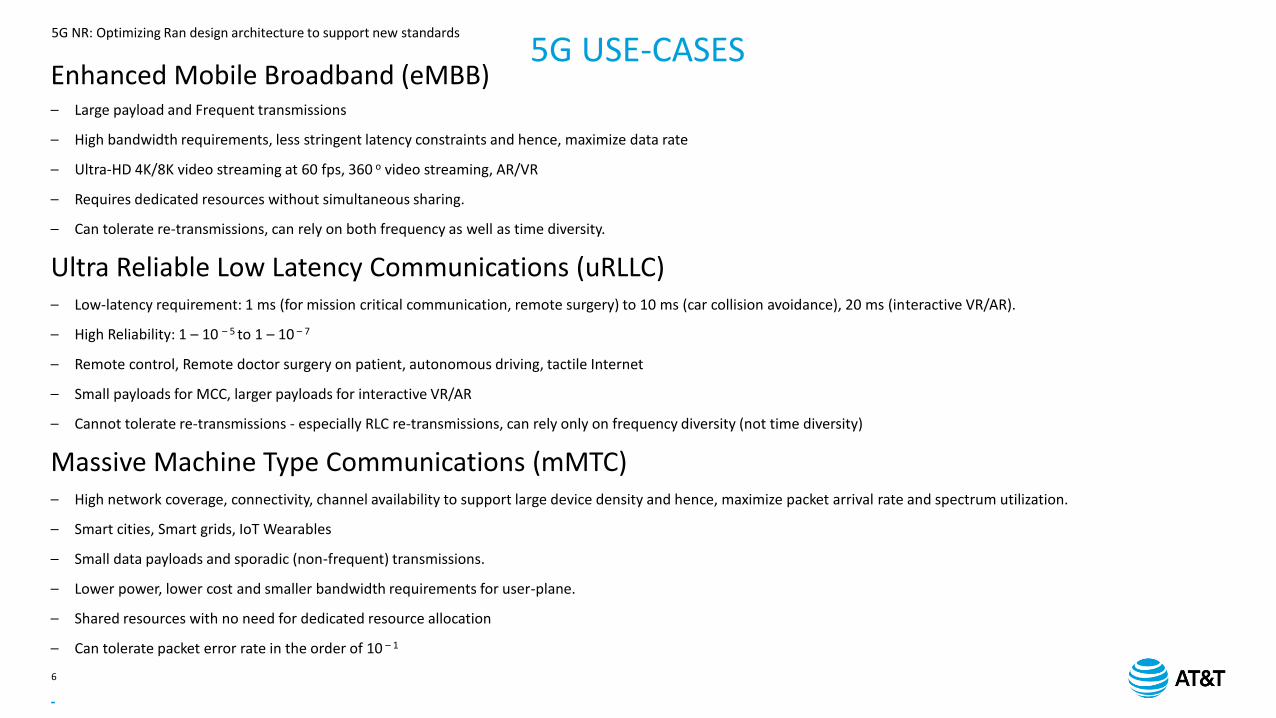
5G USE-CASESEnhanced Mobile Broadband (eMBB)– Large payload and Frequent transmissions
– High bandwidth requirements, less stringent latency constraints and hence, maximize data rate
– Ultra-HD 4K/8K video streaming at 60 fps, 360 o video streaming, AR/VR
– Requires dedicated resources without simultaneous sharing.
– Can tolerate re-transmissions, can rely on both frequency as well as time diversity.
Ultra Reliable Low Latency Communications (uRLLC)– Low-latency requirement: 1 ms (for mission critical communication, remote surgery) to 10 ms (car collision avoidance), 20 ms (interactive VR/AR).
– High Reliability: 1 – 10 – 5 to 1 – 10 – 7
– Remote control, Remote doctor surgery on patient, autonomous driving, tactile Internet
– Small payloads for MCC, larger payloads for interactive VR/AR
– Cannot tolerate re-transmissions - especially RLC re-transmissions, can rely only on frequency diversity (not time diversity)
Massive Machine Type Communications (mMTC)– High network coverage, connectivity, channel availability to support large device density and hence, maximize packet arrival rate and spectrum utilization.
– Smart cities, Smart grids, IoT Wearables
– Small data payloads and sporadic (non-frequent) transmissions.
– Lower power, lower cost and smaller bandwidth requirements for user-plane.
– Shared resources with no need for dedicated resource allocation
– Can tolerate packet error rate in the order of 10 – 1
-
5G NR: Optimizing Ran design architecture to support new standards
7
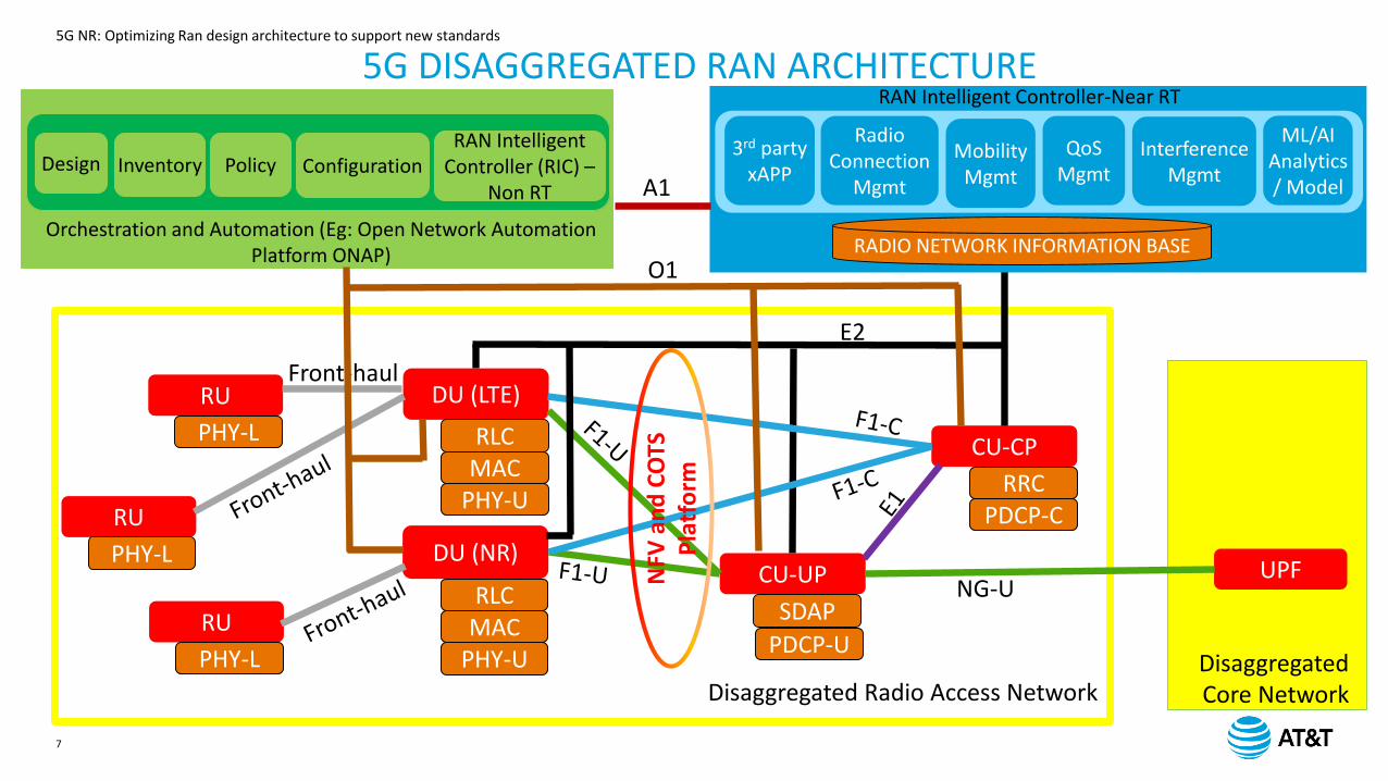
5G DISAGGREGATED RAN ARCHITECTURE
Disaggregated Radio Access Network
CU-CP
RRCPDCP-C
CU-UP
PDCP-U
DU (LTE)
RLCMAC
PHY-U
DU (NR)
RLCMAC
PHY-U
RU
E2
PHY-L
RU
PHY-L
RU
PHY-L
Front-haul
Disaggregated Core Network
UPFNG-U
SDAP
RAN Intelligent Controller-Near RT
3rd party xAPP
Radio Connection
Mgmt
MobilityMgmt
QoSMgmt
InterferenceMgmt
ML/AIAnalytics/ Model
RADIO NETWORK INFORMATION BASE
Design Inventory Policy ConfigurationRAN Intelligent
Controller (RIC) –Non RT
Orchestration and Automation (Eg: Open Network Automation Platform ONAP)
A1
O1
NFV
an
d C
OTS
P
latf
orm
5G NR: Optimizing Ran design architecture to support new standards
8
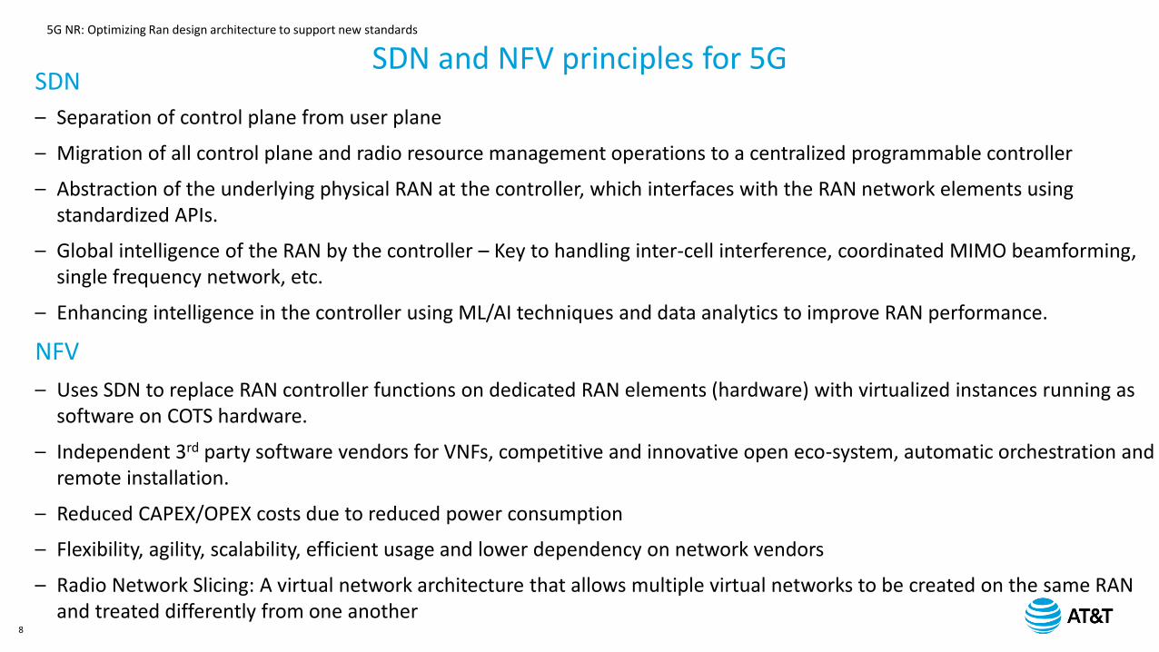
SDN and NFV principles for 5GSDN
– Separation of control plane from user plane
– Migration of all control plane and radio resource management operations to a centralized programmable controller
– Abstraction of the underlying physical RAN at the controller, which interfaces with the RAN network elements using standardized APIs.
– Global intelligence of the RAN by the controller – Key to handling inter-cell interference, coordinated MIMO beamforming, single frequency network, etc.
– Enhancing intelligence in the controller using ML/AI techniques and data analytics to improve RAN performance.
NFV
– Uses SDN to replace RAN controller functions on dedicated RAN elements (hardware) with virtualized instances running as software on COTS hardware.
– Independent 3rd party software vendors for VNFs, competitive and innovative open eco-system, automatic orchestration and remote installation.
– Reduced CAPEX/OPEX costs due to reduced power consumption
– Flexibility, agility, scalability, efficient usage and lower dependency on network vendors
– Radio Network Slicing: A virtual network architecture that allows multiple virtual networks to be created on the same RAN and treated differently from one another
5G NR: Optimizing Ran design architecture to support new standards
9
5G NR: PHY LAYER ENHANCEMENTS
5G NR: Optimizing Ran design architecture to support new standards
10
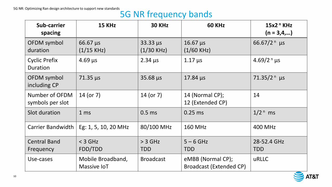
5G NR frequency bandsSub-carrier
spacing15 KHz 30 KHz 60 KHz 15x2 n KHz
(n = 3,4,…)
OFDM symbol duration
66.67 µs (1/15 KHz)
33.33 µs(1/30 KHz)
16.67 µs(1/60 KHz)
66.67/2 n µs
Cyclic Prefix Duration
4.69 µs 2.34 µs 1.17 µs 4.69/2 n µs
OFDM symbol including CP
71.35 µs 35.68 µs 17.84 µs 71.35/2 n µs
Number of OFDM symbols per slot
14 (or 7) 14 (or 7) 14 (Normal CP);12 (Extended CP)
14
Slot duration 1 ms 0.5 ms 0.25 ms 1/2 n ms
Carrier Bandwidth Eg: 1, 5, 10, 20 MHz 80/100 MHz 160 MHz 400 MHz
Central Band Frequency
< 3 GHzFDD/TDD
> 3 GHzTDD
5 – 6 GHzTDD
28-52.4 GHzTDD
Use-cases Mobile Broadband, Massive IoT
Broadcast eMBB (Normal CP);Broadcast (Extended CP)
uRLLC
5G NR: Optimizing Ran design architecture to support new standards
11
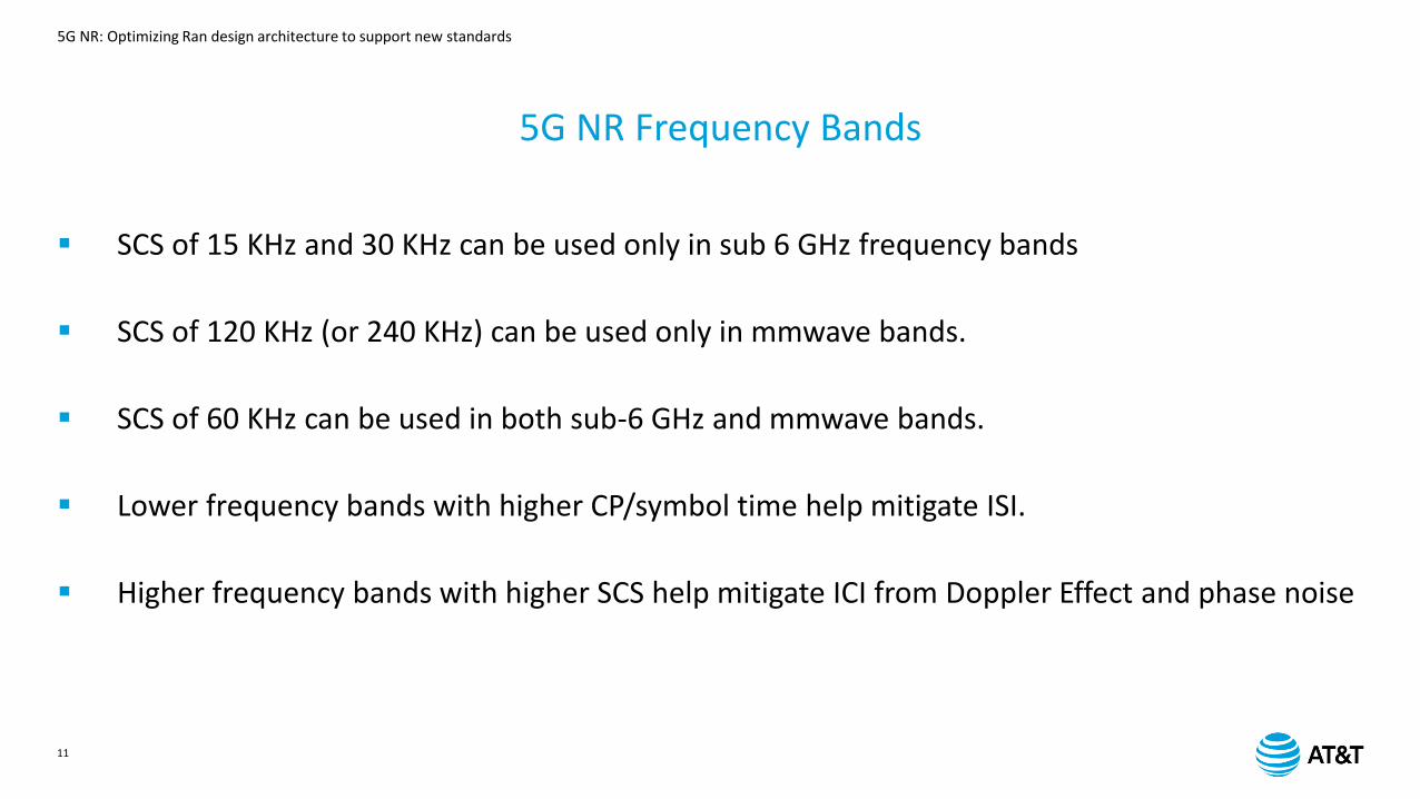
▪ SCS of 15 KHz and 30 KHz can be used only in sub 6 GHz frequency bands
▪ SCS of 120 KHz (or 240 KHz) can be used only in mmwave bands.
▪ SCS of 60 KHz can be used in both sub-6 GHz and mmwave bands.
▪ Lower frequency bands with higher CP/symbol time help mitigate ISI.
▪ Higher frequency bands with higher SCS help mitigate ICI from Doppler Effect and phase noise
5G NR Frequency Bands
5G NR: Optimizing Ran design architecture to support new standards
12
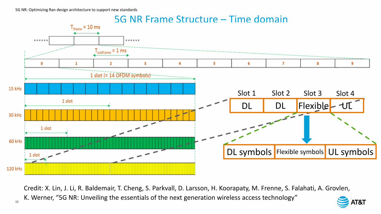
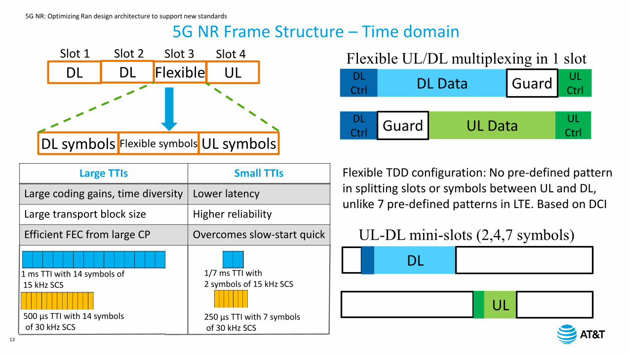
5G NR Frame Structure – Time domain
Credit: X. Lin, J. Li, R. Baldemair, T. Cheng, S. Parkvall, D. Larsson, H. Koorapaty, M. Frenne, S. Falahati, A. Grovlen,
K. Werner, “5G NR: Unveiling the essentials of the next generation wireless access technology”
S
ULFlexibleDLDL
DL symbols Flexible symbols UL symbols
Slot 1 Slot 2 Slot 3 Slot 4
5G NR: Optimizing Ran design architecture to support new standards
13
ULFlexibleDLDL
DL symbols Flexible symbols UL symbols
Slot 1 Slot 2 Slot 3 Slot 4
DLCtrl DL Data Guard
ULCtrl
DLCtrl Guard UL Data
ULCtrl
DL
UL
Flexible TDD configuration: No pre-defined pattern in splitting slots or symbols between UL and DL, unlike 7 pre-defined patterns in LTE. Based on DCI
Large TTIs Small TTIs
Large coding gains, time diversity Lower latency
Large transport block size Higher reliability
Efficient FEC from large CP Overcomes slow-start quick
1 ms TTI with 14 symbols of15 kHz SCS
500 µs TTI with 14 symbolsof 30 kHz SCS
1/7 ms TTI with 2 symbols of 15 kHz SCS
250 µs TTI with 7 symbolsof 30 kHz SCS
Flexible UL/DL multiplexing in 1 slot
UL-DL mini-slots (2,4,7 symbols)
5G NR Frame Structure – Time domain
5G NR: Optimizing Ran design architecture to support new standards
14
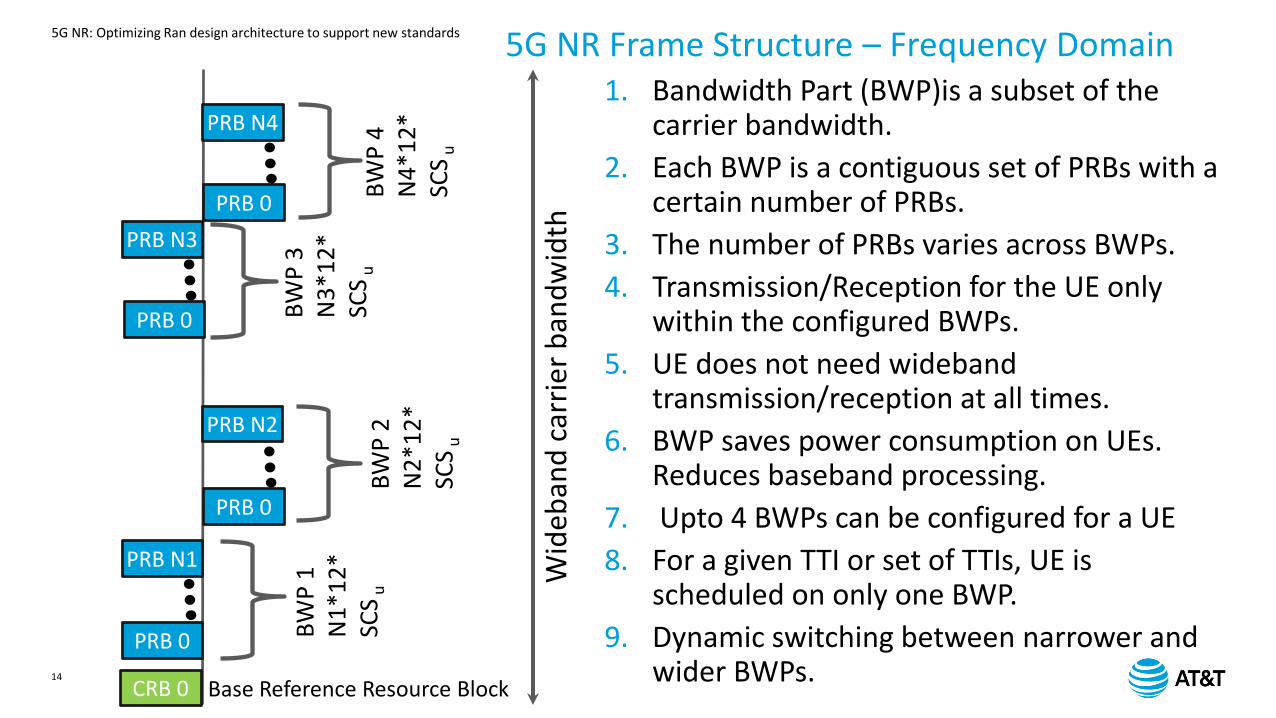
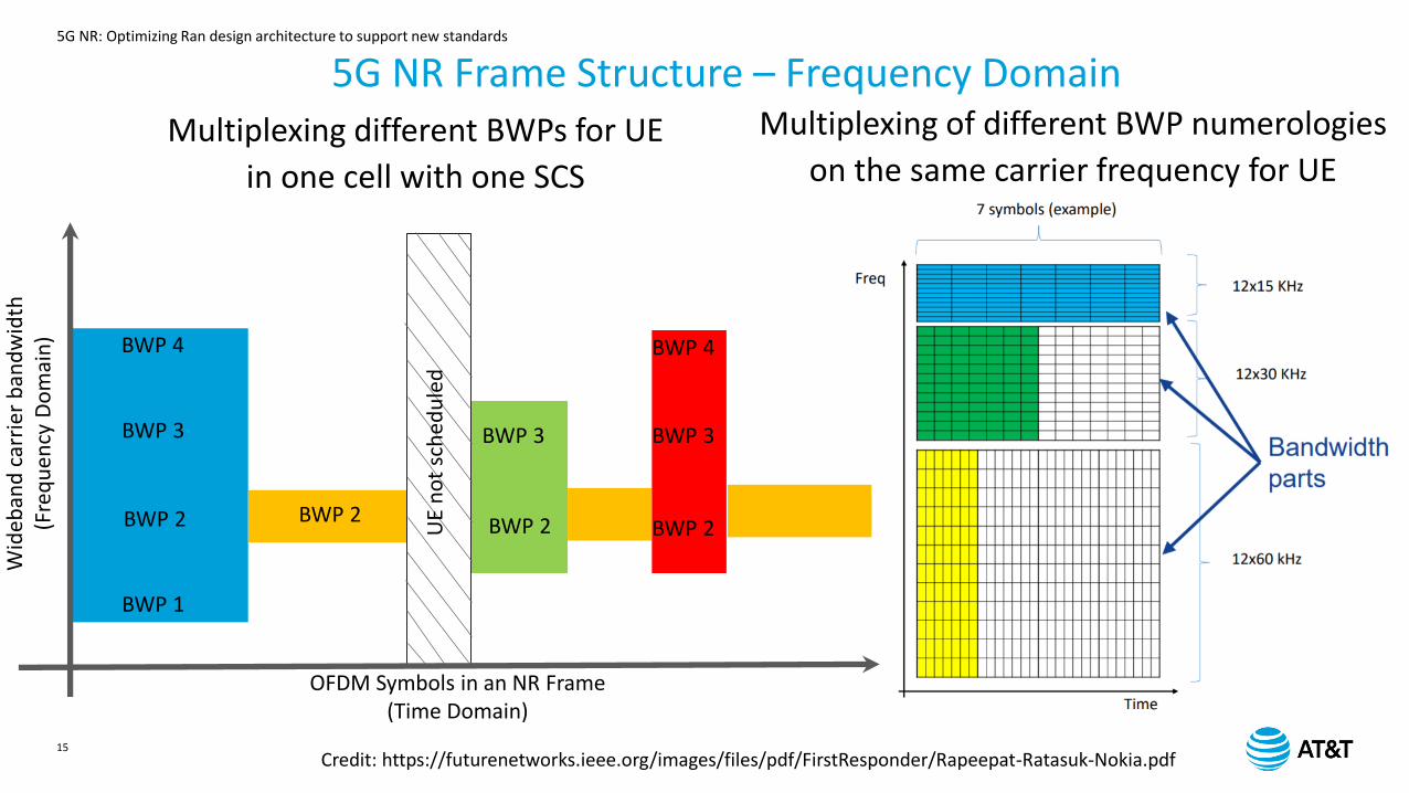
5G NR Frame Structure – Frequency Domain
PRB 0
PRB N1
PRB 0
PRB N2
PRB 0
PRB N3
PRB 0
PRB N4
BW
P 1
N1
*12
*SC
Su
B
WP
2N
2*1
2*
SCS
u
BW
P 4
N4
*12
*SC
Su
BW
P 3
N3
*12
*SC
Su
CRB 0 Base Reference Resource Block
Wid
eban
d c
arri
er
ban
dw
idth
1. Bandwidth Part (BWP)is a subset of the carrier bandwidth.
2. Each BWP is a contiguous set of PRBs with a certain number of PRBs.
3. The number of PRBs varies across BWPs.
4. Transmission/Reception for the UE only within the configured BWPs.
5. UE does not need wideband transmission/reception at all times.
6. BWP saves power consumption on UEs. Reduces baseband processing.
7. Upto 4 BWPs can be configured for a UE
8. For a given TTI or set of TTIs, UE is scheduled on only one BWP.
9. Dynamic switching between narrower and wider BWPs.
5G NR: Optimizing Ran design architecture to support new standards
15
BWP 1
BWP 2
BWP 3
BWP 4
BWP 2 BWP 2
BWP 3
BWP 2
BWP 3
BWP 4
Wid
eban
d c
arri
er b
and
wid
th(F
req
uen
cy D
om
ain
)
OFDM Symbols in an NR Frame(Time Domain)
UE
no
t sc
hed
ule
d
5G NR Frame Structure – Frequency DomainMultiplexing different BWPs for UE
in one cell with one SCS
Multiplexing of different BWP numerologies
on the same carrier frequency for UE
Credit: https://futurenetworks.ieee.org/images/files/pdf/FirstResponder/Rapeepat-Ratasuk-Nokia.pdf
5G NR: Optimizing Ran design architecture to support new standards
16
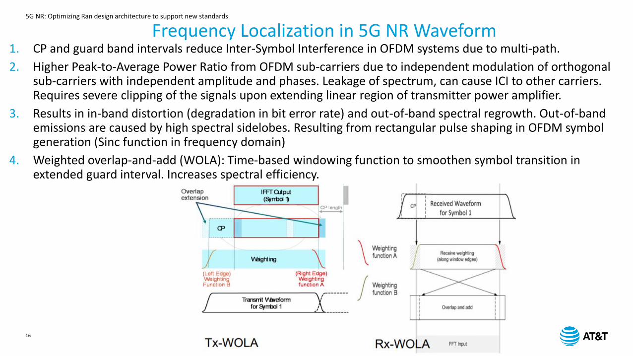
Frequency Localization in 5G NR Waveform1. CP and guard band intervals reduce Inter-Symbol Interference in OFDM systems due to multi-path.
2. Higher Peak-to-Average Power Ratio from OFDM sub-carriers due to independent modulation of orthogonal sub-carriers with independent amplitude and phases. Leakage of spectrum, can cause ICI to other carriers. Requires severe clipping of the signals upon extending linear region of transmitter power amplifier.
3. Results in in-band distortion (degradation in bit error rate) and out-of-band spectral regrowth. Out-of-band emissions are caused by high spectral sidelobes. Resulting from rectangular pulse shaping in OFDM symbol generation (Sinc function in frequency domain)
4. Weighted overlap-and-add (WOLA): Time-based windowing function to smoothen symbol transition in extended guard interval. Increases spectral efficiency.
5G NR: Optimizing Ran design architecture to support new standards
17
Massive MIMO and Enhanced Beamforming
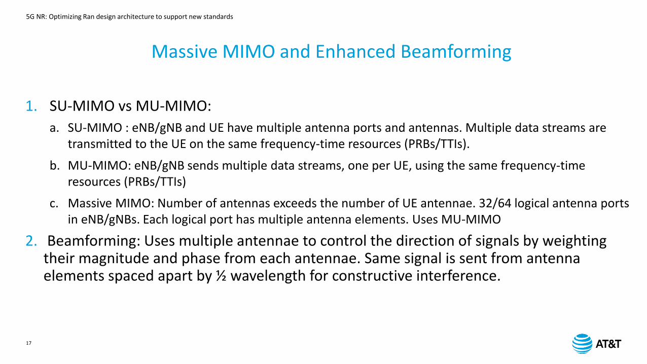
1. SU-MIMO vs MU-MIMO:
a. SU-MIMO : eNB/gNB and UE have multiple antenna ports and antennas. Multiple data streams are transmitted to the UE on the same frequency-time resources (PRBs/TTIs).
b. MU-MIMO: eNB/gNB sends multiple data streams, one per UE, using the same frequency-time resources (PRBs/TTIs)
c. Massive MIMO: Number of antennas exceeds the number of UE antennae. 32/64 logical antenna ports in eNB/gNBs. Each logical port has multiple antenna elements. Uses MU-MIMO
2. Beamforming: Uses multiple antennae to control the direction of signals by weighting their magnitude and phase from each antennae. Same signal is sent from antenna elements spaced apart by ½ wavelength for constructive interference.
5G NR: Optimizing Ran design architecture to support new standards
18
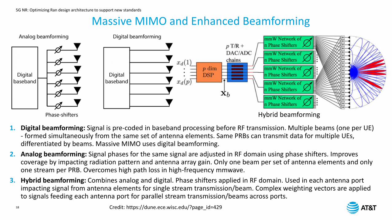
1. Digital beamforming: Signal is pre-coded in baseband processing before RF transmission. Multiple beams (one per UE) - formed simultaneously from the same set of antenna elements. Same PRBs can transmit data for multiple UEs, differentiated by beams. Massive MIMO uses digital beamforming.
2. Analog beamforming: Signal phases for the same signal are adjusted in RF domain using phase shifters. Improves coverage by impacting radiation pattern and antenna array gain. Only one beam per set of antenna elements and only one stream per PRB. Overcomes high path loss in high-frequency mmwave.
3. Hybrid beamforming: Combines analog and digital. Phase shifters applied in RF domain. Used in each antenna port impacting signal from antenna elements for single stream transmission/beam. Complex weighting vectors are applied to signals feeding each antenna port for parallel stream transmission/beams across ports.
Hybrid beamforming
Massive MIMO and Enhanced Beamforming
Credit: https://dune.ece.wisc.edu/?page_id=429
5G NR: Optimizing Ran design architecture to support new standards
19
NR Signals
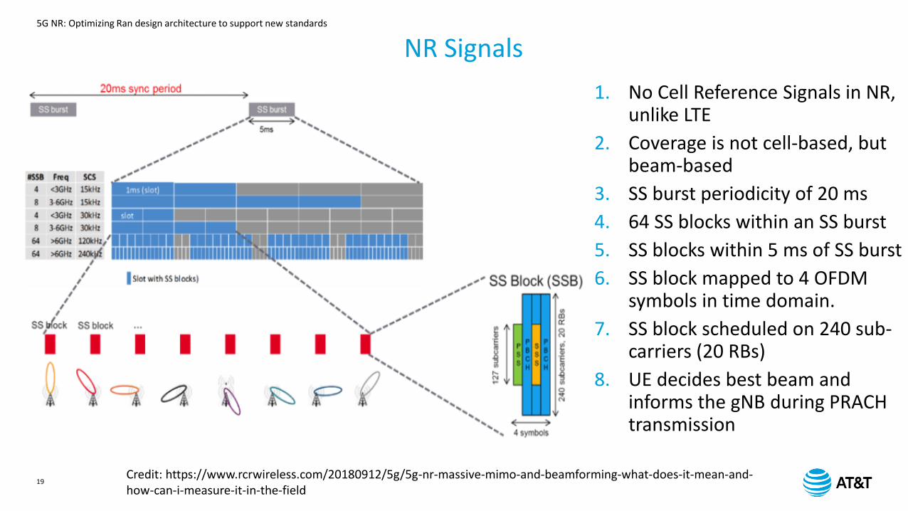
1. No Cell Reference Signals in NR, unlike LTE
2. Coverage is not cell-based, but beam-based
3. SS burst periodicity of 20 ms
4. 64 SS blocks within an SS burst
5. SS blocks within 5 ms of SS burst
6. SS block mapped to 4 OFDM symbols in time domain.
7. SS block scheduled on 240 sub-carriers (20 RBs)
8. UE decides best beam and informs the gNB during PRACH transmission
Credit: https://www.rcrwireless.com/20180912/5g/5g-nr-massive-mimo-and-beamforming-what-does-it-mean-and-how-can-i-measure-it-in-the-field

5G NR: Optimizing Ran design architecture to support new standards
20
NR Reference Signals
UL Data UL Control UL Sync
1. Demodulation Reference Signal (DMRS)– UE produces channel estimates for demod of associated PHY channel (PBCH, PDCCH, PUCCH, PDSCH, PUSCH)
2. Phase Tracking Reference Signals (PTRS)– Tracking the phase of the local oscillator at Tx and Rx to suppress phase noise/error at higher (mmwave) bands. Present in NR-PUSCH and NR-PDSCH.
3. Channel State Information – Ref Signal (CSI – RS) – DL CSI acquisition, RSRP measurements during mobility/beam/MIMO mgmt., freq/time tracking, UL reporting-based precoding. UE-specific. Periodic, semi-persistent.
4. Sounding Reference Signals (SRS) –Transmitted by UE to help gNB obtain CSI for each UE. Used for resource scheduling, link adaptation, massive MIMO/beam mgmt
Lean carrier design – Reference signal transmission only when necessaryNR PDCCHs are designed to transmit in a configurable CORESET
5G NR: Optimizing Ran design architecture to support new standards
21
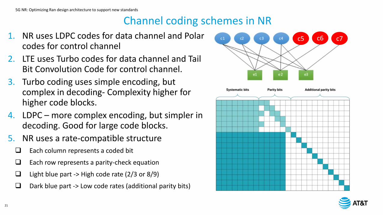
1. NR uses LDPC codes for data channel and Polar codes for control channel
2. LTE uses Turbo codes for data channel and Tail Bit Convolution Code for control channel.
3. Turbo coding uses simple encoding, but complex in decoding- Complexity higher for higher code blocks.
4. LDPC – more complex encoding, but simpler in decoding. Good for large code blocks.
5. NR uses a rate-compatible structure Each column represents a coded bit
Each row represents a parity-check equation
Light blue part -> High code rate (2/3 or 8/9)
Dark blue part -> Low code rates (additional parity bits)
Channel coding schemes in NR
c5 c6 c7
5G NR: Optimizing Ran design architecture to support new standards
22
RAN Layer enhancements for 5G NR: From MAC to RRC
5G NR: Optimizing Ran design architecture to support new standards
23
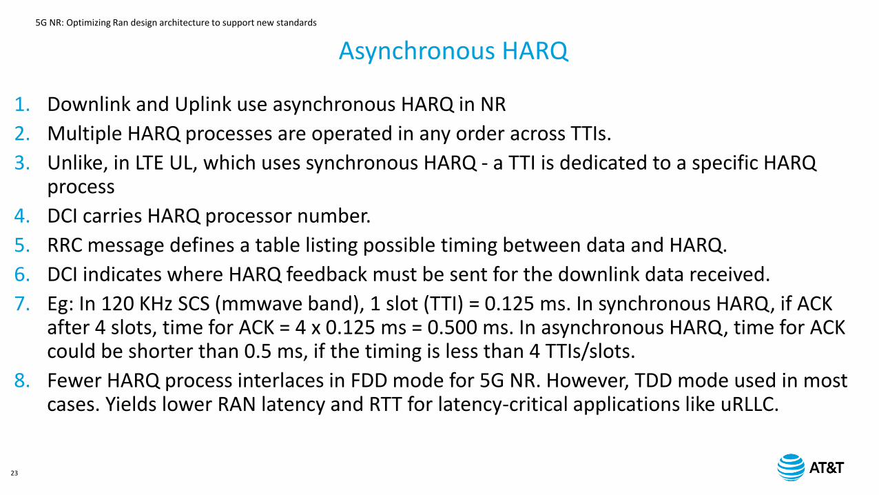
1. Downlink and Uplink use asynchronous HARQ in NR
2. Multiple HARQ processes are operated in any order across TTIs.
3. Unlike, in LTE UL, which uses synchronous HARQ - a TTI is dedicated to a specific HARQ process
4. DCI carries HARQ processor number.
5. RRC message defines a table listing possible timing between data and HARQ.
6. DCI indicates where HARQ feedback must be sent for the downlink data received.
7. Eg: In 120 KHz SCS (mmwave band), 1 slot (TTI) = 0.125 ms. In synchronous HARQ, if ACK after 4 slots, time for ACK = 4 x 0.125 ms = 0.500 ms. In asynchronous HARQ, time for ACK could be shorter than 0.5 ms, if the timing is less than 4 TTIs/slots.
8. Fewer HARQ process interlaces in FDD mode for 5G NR. However, TDD mode used in most cases. Yields lower RAN latency and RTT for latency-critical applications like uRLLC.
Asynchronous HARQ
5G NR: Optimizing Ran design architecture to support new standards
24
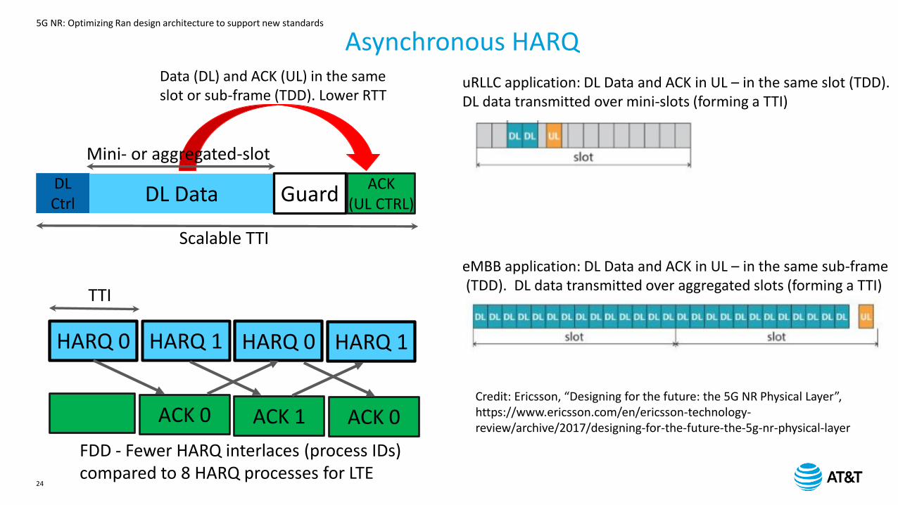
DLCtrl DL Data Guard
ACK(UL CTRL)
Scalable TTI
Data (DL) and ACK (UL) in the same slot or sub-frame (TDD). Lower RTT
Mini- or aggregated-slot
Asynchronous HARQ
uRLLC application: DL Data and ACK in UL – in the same slot (TDD). DL data transmitted over mini-slots (forming a TTI)
eMBB application: DL Data and ACK in UL – in the same sub-frame(TDD). DL data transmitted over aggregated slots (forming a TTI)
HARQ 0 HARQ 1 HARQ 0 HARQ 1
ACK 0 ACK 1 ACK 0
TTI
FDD - Fewer HARQ interlaces (process IDs) compared to 8 HARQ processes for LTE
Credit: Ericsson, “Designing for the future: the 5G NR Physical Layer”, https://www.ericsson.com/en/ericsson-technology-review/archive/2017/designing-for-the-future-the-5g-nr-physical-layer
5G NR: Optimizing Ran design architecture to support new standards
25
SS
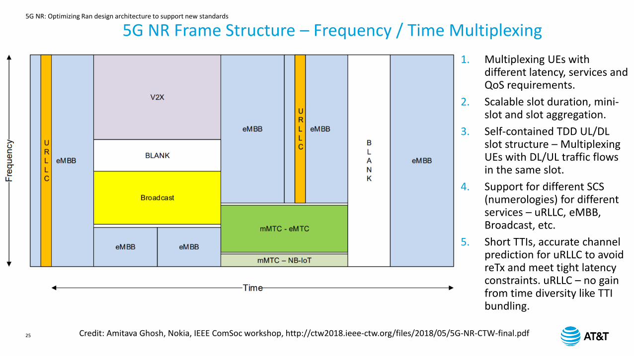
5G NR Frame Structure – Frequency / Time Multiplexing
1. Multiplexing UEs with different latency, services and QoS requirements.
2. Scalable slot duration, mini-slot and slot aggregation.
3. Self-contained TDD UL/DL slot structure – Multiplexing UEs with DL/UL traffic flows in the same slot.
4. Support for different SCS (numerologies) for different services – uRLLC, eMBB, Broadcast, etc.
5. Short TTIs, accurate channel prediction for uRLLC to avoid reTx and meet tight latency constraints. uRLLC – no gain from time diversity like TTI bundling.
Credit: Amitava Ghosh, Nokia, IEEE ComSoc workshop, http://ctw2018.ieee-ctw.org/files/2018/05/5G-NR-CTW-final.pdf
5G NR: Optimizing Ran design architecture to support new standards
n
n+4
n+8
n+12
n+16
n+20
m
m+4
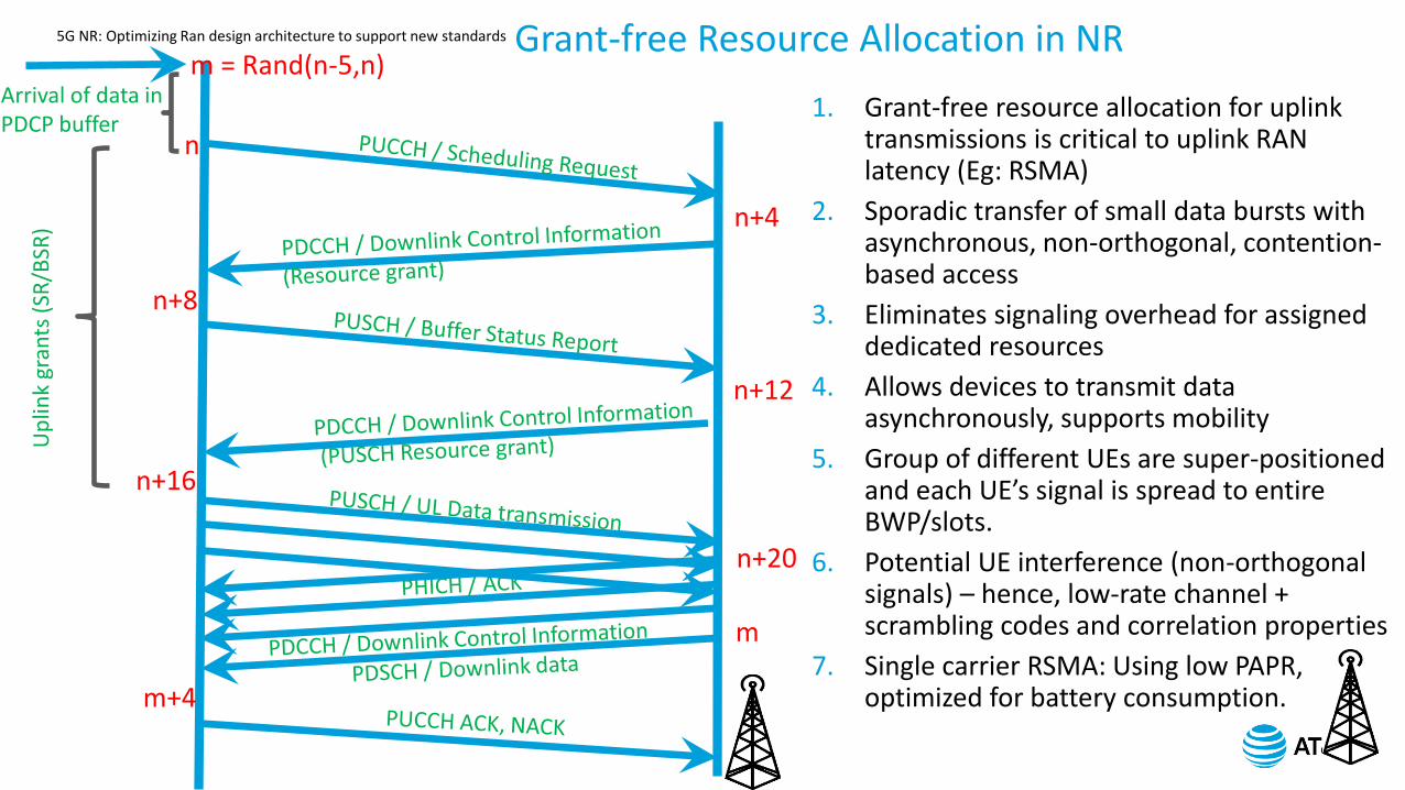
Arrival of data in PDCP buffer
m = Rand(n-5,n)U
plin
k gr
ants
(SR
/BSR
)Grant-free Resource Allocation in NR
1. Grant-free resource allocation for uplink transmissions is critical to uplink RAN latency (Eg: RSMA)
2. Sporadic transfer of small data bursts with asynchronous, non-orthogonal, contention-based access
3. Eliminates signaling overhead for assigned dedicated resources
4. Allows devices to transmit data asynchronously, supports mobility
5. Group of different UEs are super-positioned and each UE’s signal is spread to entire BWP/slots.
6. Potential UE interference (non-orthogonal signals) – hence, low-rate channel + scrambling codes and correlation properties
7. Single carrier RSMA: Using low PAPR, optimized for battery consumption.
5G NR: Optimizing Ran design architecture to support new standards
27
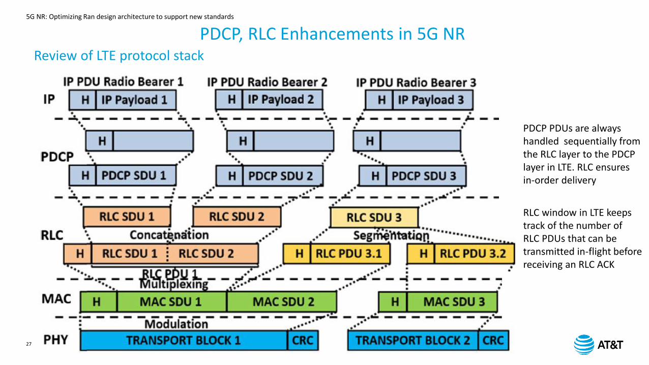
PDCP, RLC Enhancements in 5G NRReview of LTE protocol stack
PDCP PDUs are always handled sequentially from the RLC layer to the PDCP layer in LTE. RLC ensuresin-order delivery
RLC window in LTE keeps track of the number of RLC PDUs that can be transmitted in-flight beforereceiving an RLC ACK
5G NR: Optimizing Ran design architecture to support new standards
28
PDCP, RLC Enhancements in 5G NR
IP Core
Network
PDCPBuffer
RLC TxBuffer
RLC ReTxBuffer
PDCPPDU
MAC Tx PDU Buffer
RLCSDU
RLCPDU 1
RLCPDU 2
RLCPDU 3
RLCPDU n……
MACSDU
1
2
3
4
6
12
13
MAC ReTx PDU Buffer
8
USEREQUIPMENT
7
9
10
11
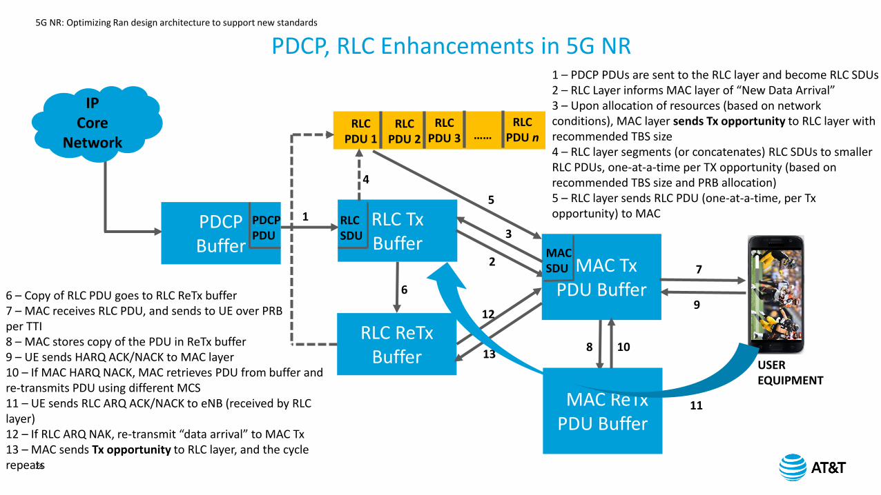
1 – PDCP PDUs are sent to the RLC layer and become RLC SDUs2 – RLC Layer informs MAC layer of “New Data Arrival”3 – Upon allocation of resources (based on network conditions), MAC layer sends Tx opportunity to RLC layer with recommended TBS size4 – RLC layer segments (or concatenates) RLC SDUs to smaller RLC PDUs, one-at-a-time per TX opportunity (based on recommended TBS size and PRB allocation)5 – RLC layer sends RLC PDU (one-at-a-time, per Tx opportunity) to MAC
6 – Copy of RLC PDU goes to RLC ReTx buffer7 – MAC receives RLC PDU, and sends to UE over PRBper TTI 8 – MAC stores copy of the PDU in ReTx buffer9 – UE sends HARQ ACK/NACK to MAC layer10 – If MAC HARQ NACK, MAC retrieves PDU from buffer and re-transmits PDU using different MCS11 – UE sends RLC ARQ ACK/NACK to eNB (received by RLC layer)12 – If RLC ARQ NAK, re-transmit “data arrival” to MAC Tx13 – MAC sends Tx opportunity to RLC layer, and the cycle repeats
5
5G NR: Optimizing Ran design architecture to support new standards
29
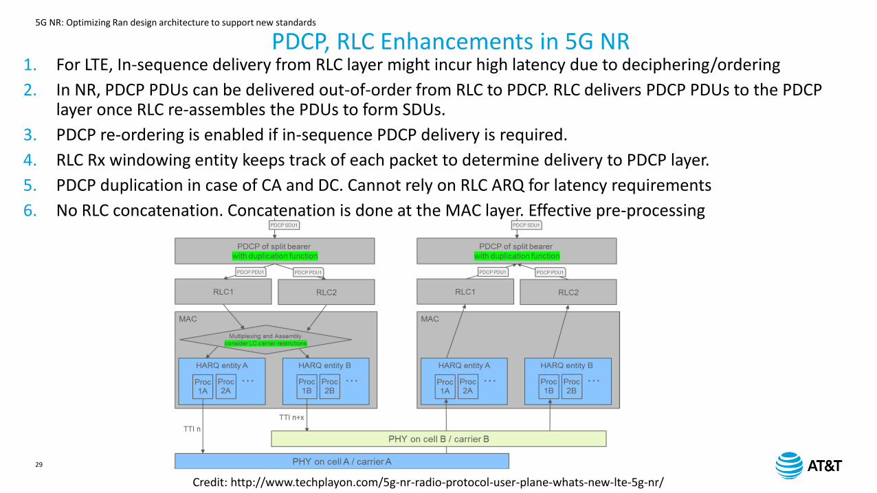
1. For LTE, In-sequence delivery from RLC layer might incur high latency due to deciphering/ordering
2. In NR, PDCP PDUs can be delivered out-of-order from RLC to PDCP. RLC delivers PDCP PDUs to the PDCP layer once RLC re-assembles the PDUs to form SDUs.
3. PDCP re-ordering is enabled if in-sequence PDCP delivery is required.
4. RLC Rx windowing entity keeps track of each packet to determine delivery to PDCP layer.
5. PDCP duplication in case of CA and DC. Cannot rely on RLC ARQ for latency requirements
6. No RLC concatenation. Concatenation is done at the MAC layer. Effective pre-processing
PDCP, RLC Enhancements in 5G NR
Credit: http://www.techplayon.com/5g-nr-radio-protocol-user-plane-whats-new-lte-5g-nr/
5G NR: Optimizing Ran design architecture to support new standards
30
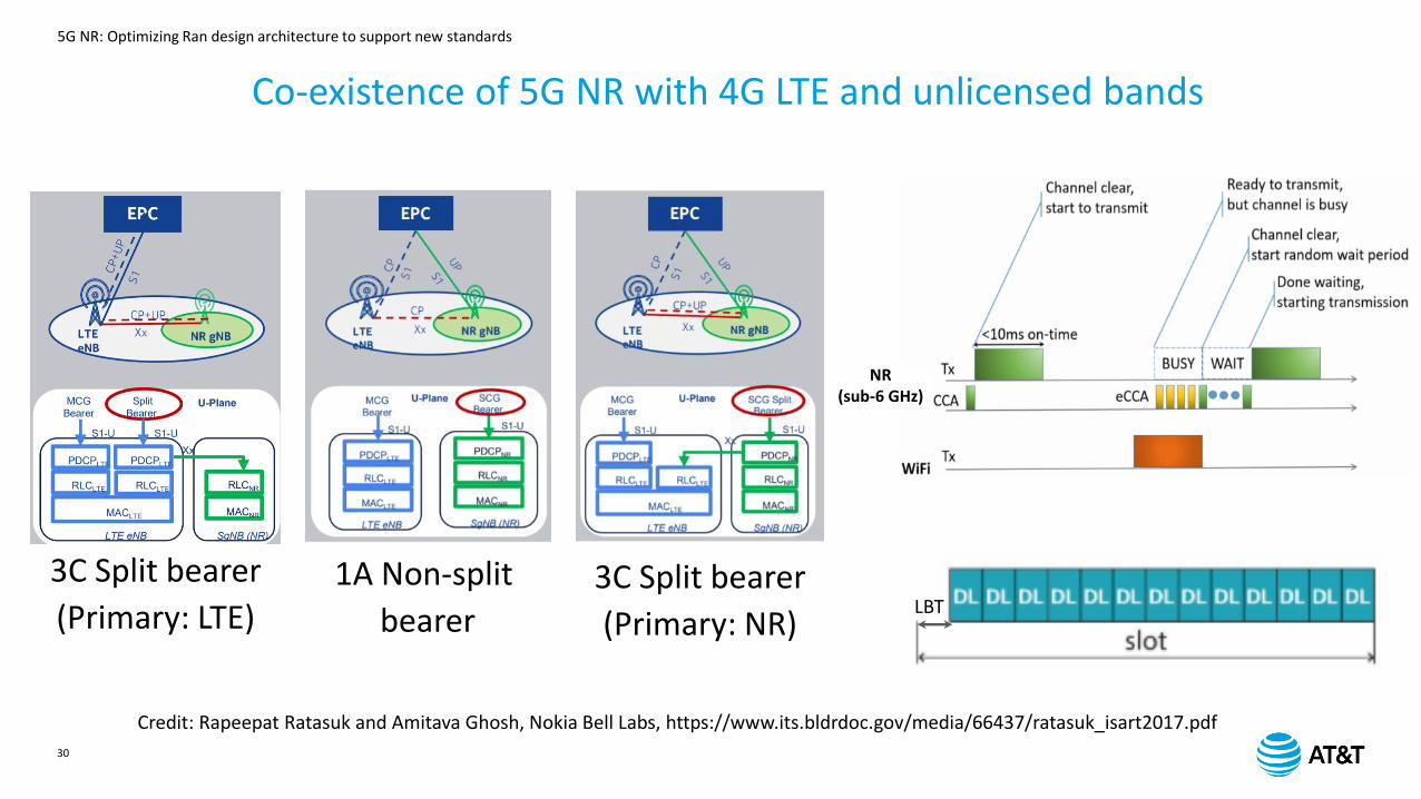
Co-existence of 5G NR with 4G LTE and unlicensed bands
3C Split bearer
(Primary: LTE)1A Non-split
bearer3C Split bearer
(Primary: NR)
NR(sub-6 GHz)
LBT
Credit: Rapeepat Ratasuk and Amitava Ghosh, Nokia Bell Labs, https://www.its.bldrdoc.gov/media/66437/ratasuk_isart2017.pdf
5G NR: Optimizing Ran design architecture to support new standards
31
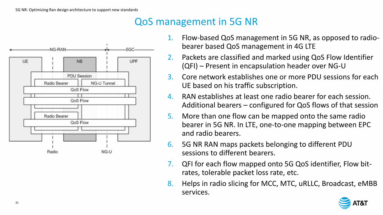
QoS management in 5G NR
1. Flow-based QoS management in 5G NR, as opposed to radio-bearer based QoS management in 4G LTE
2. Packets are classified and marked using QoS Flow Identifier (QFI) – Present in encapsulation header over NG-U
3. Core network establishes one or more PDU sessions for each UE based on his traffic subscription.
4. RAN establishes at least one radio bearer for each session. Additional bearers – configured for QoS flows of that session
5. More than one flow can be mapped onto the same radio bearer in 5G NR. In LTE, one-to-one mapping between EPC and radio bearers.
6. 5G NR RAN maps packets belonging to different PDU sessions to different bearers.
7. QFI for each flow mapped onto 5G QoS identifier, Flow bit-rates, tolerable packet loss rate, etc.
8. Helps in radio slicing for MCC, MTC, uRLLC, Broadcast, eMBBservices.
5G NR: Optimizing Ran design architecture to support new standards
32
Intelligence in the RAN and cross-layer implications
5G NR: Optimizing Ran design architecture to support new standards
33
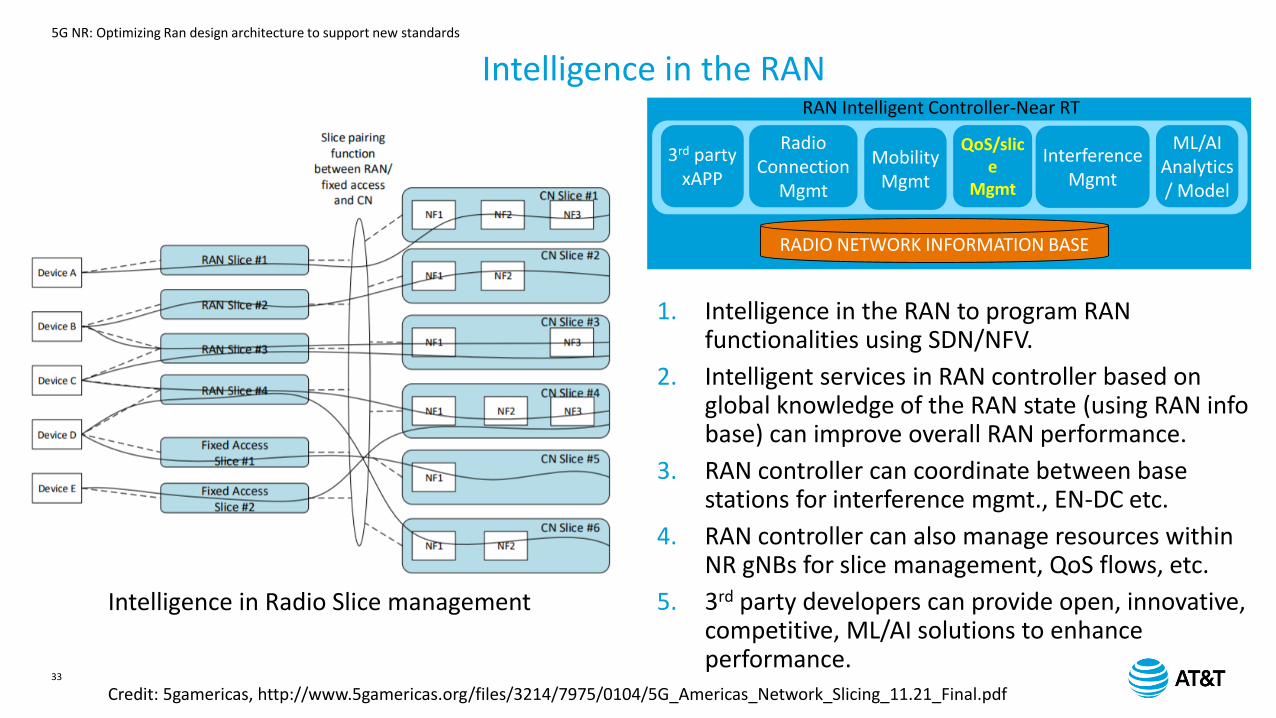
Intelligence in the RAN
Credit: 5gamericas, http://www.5gamericas.org/files/3214/7975/0104/5G_Americas_Network_Slicing_11.21_Final.pdf
RAN Intelligent Controller-Near RT
3rd party xAPP
Radio Connection
Mgmt
MobilityMgmt
QoS/slice
Mgmt
InterferenceMgmt
ML/AIAnalytics/ Model
RADIO NETWORK INFORMATION BASE
1. Intelligence in the RAN to program RAN functionalities using SDN/NFV.
2. Intelligent services in RAN controller based on global knowledge of the RAN state (using RAN info base) can improve overall RAN performance.
3. RAN controller can coordinate between base stations for interference mgmt., EN-DC etc.
4. RAN controller can also manage resources within NR gNBs for slice management, QoS flows, etc.
5. 3rd party developers can provide open, innovative, competitive, ML/AI solutions to enhance performance.
Intelligence in Radio Slice management
5G NR: Optimizing Ran design architecture to support new standards
34
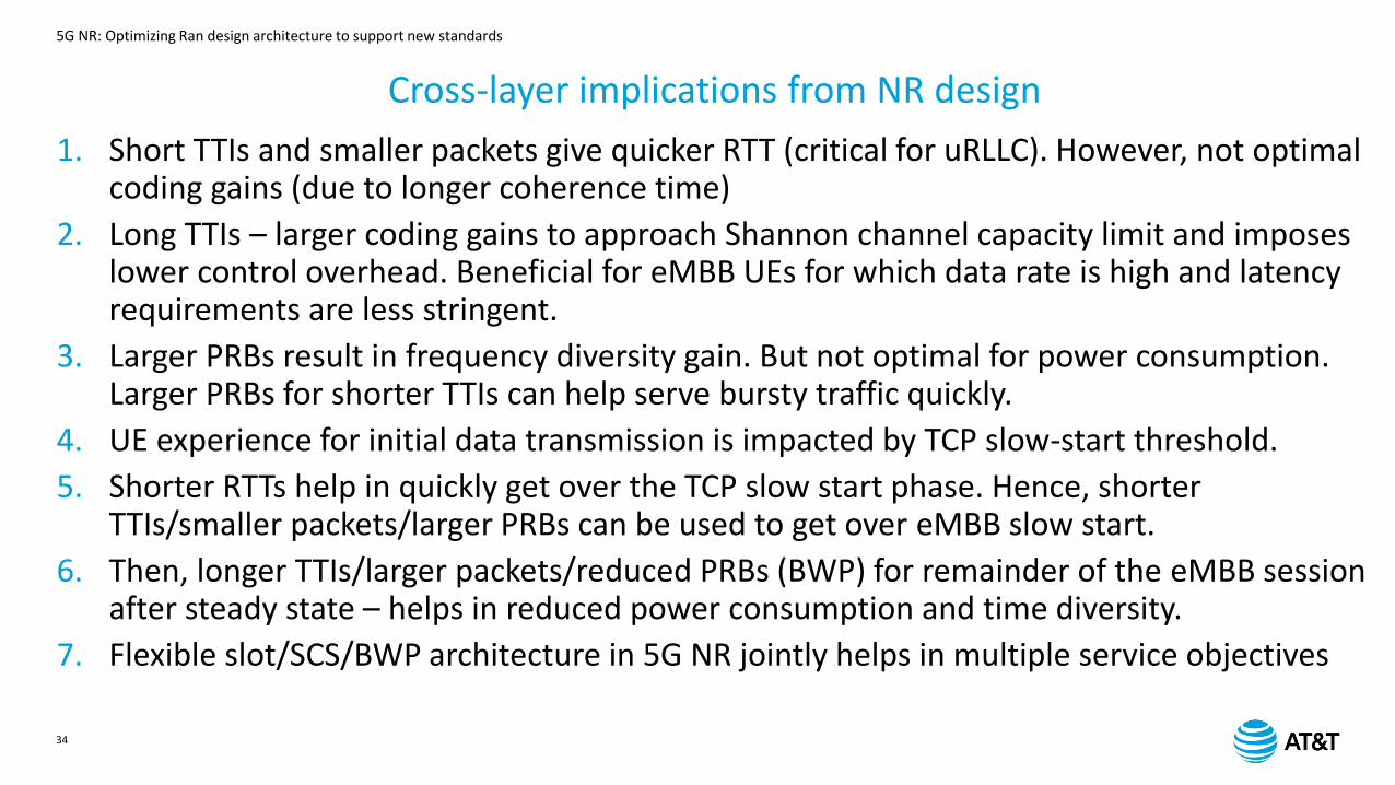
Cross-layer implications from NR design
1. Short TTIs and smaller packets give quicker RTT (critical for uRLLC). However, not optimal coding gains (due to longer coherence time)
2. Long TTIs – larger coding gains to approach Shannon channel capacity limit and imposes lower control overhead. Beneficial for eMBB UEs for which data rate is high and latency requirements are less stringent.
3. Larger PRBs result in frequency diversity gain. But not optimal for power consumption. Larger PRBs for shorter TTIs can help serve bursty traffic quickly.
4. UE experience for initial data transmission is impacted by TCP slow-start threshold.
5. Shorter RTTs help in quickly get over the TCP slow start phase. Hence, shorter TTIs/smaller packets/larger PRBs can be used to get over eMBB slow start.
6. Then, longer TTIs/larger packets/reduced PRBs (BWP) for remainder of the eMBB session after steady state – helps in reduced power consumption and time diversity.
7. Flexible slot/SCS/BWP architecture in 5G NR jointly helps in multiple service objectives
5G NR: Optimizing Ran design architecture to support new standards
35
SUMMARY
1. 5G Requirements, use-cases and frequency bands
2. 5G NR frame structure
3. Flexible slot, TTI, SCS, numerology – Time and frequency domains.
4. PHY layer enhancements (Massive MIMO, enhanced beamforming, modulation)
5. MAC layer enhancements (asynchronous HARQ, flexible scheduling, grant-free scheduling)
6. RLC layer enhancements (No RLC ARQ)
7. PDCP layer enhancements (PDCP Duplication, allowing PDCP out-of-order delivery)
8. NR Deployments and co-existence (Dual Connectivity, Spectrum sharing)
9. 5G NR QoS
10. Intelligence in NR and cross-layer implications for user experience.

5G NR: Optimizing Ran design architecture to support new standards