Embed Size (px)
Citation preview
8/3/2019 5968-3809E (Agilent LCR Meter)
http://slidepdf.com/reader/full/5968-3809e-agilent-lcr-meter 1/32
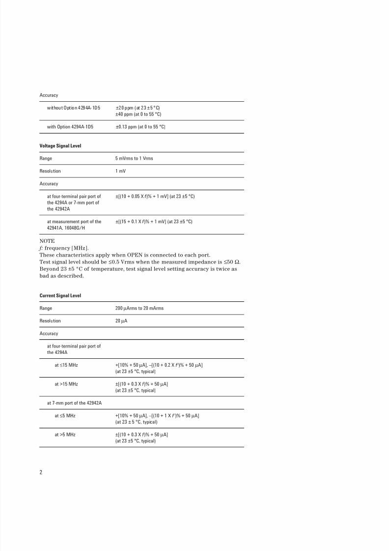
SpecificationsSpecifications describe the instrument’s warranted performance over the tem-
perature range of 0 °C to 40 °C (except as noted). Supplemental performance
characteristics are intended to provide information that is useful in applying
the instrument by given non-warranted performance parameters. These are
denoted as SPC (supplemental performance characteristics), typical, or nomi-
nal. Warm-up time must be greater than or equal to 30 minutes after power on
for all specifications.
Basic Characteristics
Measurement Parameter
Impedance Parameters |Z|-θ, R-X, Ls-Rs, Ls-Q, Cs-Rs, Cs-Q, Cs-D, |Y|-θ, G-B, Lp-G,
Lp-Q, Cp-G, Cp-Q, Cp-D, Complex Z-Y, |Z|-Ls, |Z|-Cs, |Z|-Lp,
|Z|-Cp, |Z|-Rs, |Z|-Q, |Z|-D, Lp-Rp, Cp-Rp
Measurement Terminal
Configuration Four-terminal pair configuration
Connector type Four BNC (female) connectors. Can be converted to one port ter-
minal using the Agilent 42942A Terminal Adapter (7-mm port) or
42941A Impedance Probe (3.5-mm port).
Source Characteristics
Frequency
Range 40 Hz to 110 MHz
Resolution 1 mHz
Agilent 4294A
Precision Impedance AnalyzerData Sheet
8/3/2019 5968-3809E (Agilent LCR Meter)
http://slidepdf.com/reader/full/5968-3809e-agilent-lcr-meter 2/32
2
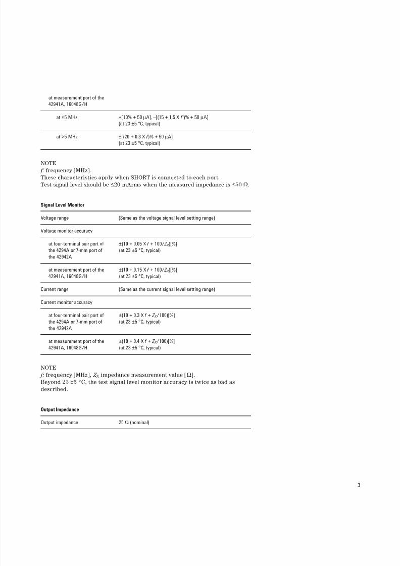
Accuracy
without Option 4294A-1D5 ±20 ppm (at 23 ±5 °C)
±40 ppm (at 0 to 55 °C)
with Option 4294A-1D5 ±0.13 ppm (at 0 to 55 °C)
Voltage Signal Level
Range 5 mVrms to 1 Vrms
Resolution 1 mV
Accuracy
at four-terminal pair port of ±[(10 + 0.05 X f )% + 1 mV] (at 23 ±5 °C)
the 4294A or 7-mm port of
the 42942A
at measurement port of the ±[(15 + 0.1 X f )% + 1 mV] (at 23 ±5 °C)
42941A, 16048G/H
NOTE
f: frequency [MHz].
These characteristics apply when OPEN is connected to each port.
Test signal level should be ≤0.5 Vrms when the measured impedance is ≤50 Ω.
Beyond 23 ±5 °C of temperature, test signal level setting accuracy is twice as
bad as described.
Current Signal Level
Range 200 µArms to 20 mArms
Resolution 20 µA
Accuracy
at four-terminal pair port of
the 4294A
at ≤15 MHz +[10% + 50 µA], –[(10 + 0.2 X f 2)% + 50 µA]
(at 23 ±5 °C, typical)
at >15 MHz ±[(10 + 0.3 X f )% + 50 µA](at 23 ±5 °C, typical)
at 7-mm port of the 42942A
at ≤5 MHz +[10% + 50 µA], –[(10 + 1 X f 2)% + 50 µA]
(at 23 ± 5 °C, typical)
at >5 MHz ±[(10 + 0.3 X f )% + 50 µA]
(at 23 ±5 °C, typical)
8/3/2019 5968-3809E (Agilent LCR Meter)
http://slidepdf.com/reader/full/5968-3809e-agilent-lcr-meter 3/32
3
at measurement port of the42941A, 16048G/H
at ≤5 MHz +[10% + 50 µA], –[(15 + 1.5 X f 2)% + 50 µA]
(at 23 ±5 °C, typical)
at >5 MHz ±[(20 + 0.3 X f )% + 50 µA]
(at 23 ±5 °C, typical)
NOTE
f: frequency [MHz].
These characteristics apply when SHORT is connected to each port.
Test signal level should be ≤20 mArms when the measured impedance is ≤50 Ω.
Signal Level Monitor
Voltage range (Same as the voltage signal level setting range)
Voltage monitor accuracy
at four-terminal pair port of ±(10 + 0.05 X f + 100/ Z X )[%]
the 4294A or 7-mm port of (at 23 ±5 °C, typical)
the 42942A
at measurement port of the ±(10 + 0.15 X f + 100/ Z X )[%]
42941A, 16048G/H (at 23 ±5 °C, typical)
Current range (Same as the current signal level setting range)
Current monitor accuracy
at four-terminal pair port of ±(10 + 0.3 X f + Z X /100)[%]
the 4294A or 7-mm port of (at 23 ±5 °C, typical)
the 42942A
at measurement port of the ±(10 + 0.4 X f + Z X /100)[%]
42941A, 16048G/H (at 23 ±5 °C, typical)
NOTE
f: frequency [MHz], Z X impedance measurement value [Ω].
Beyond 23 ±5 °C, the test signal level monitor accuracy is twice as bad as
described.
Output Impedance
Output impedance 25 Ω (nominal)
8/3/2019 5968-3809E (Agilent LCR Meter)
http://slidepdf.com/reader/full/5968-3809e-agilent-lcr-meter 4/32
4
DC Bias Function
DC voltage bias
Range 0 to ±40 V (see Figure 1)
Resolution 1 mV
Accuracy ±[0.1% + (5 + 30 X |I mon|) mV](at 23 ±5 °C)
±[0.2% + (10 + 30 X |I mon|) mV](beyond 23 ±5 °C)
DC current bias
Range 0 to ±100 mA (see Figure 1)
Resolution 40 µA
Accuracy ±[2% + (0.2 + |V mon|/20) mA] (at 23 ±5 °C)
±[4% + (0.4 + |V mon|/20) mA] (beyond 23 ±5 °C)
DC voltage bias at constant
voltage mode
Range 0 to ±40 V (see Figure 1)
Resolution 1 mV
Accuracy ±[0.5% + (5 + Z d X |I mon|) mV] (at 23 ±5 °C, typical)
±[1.0% + (10 + Z d X |I mon|) mV] (beyond 23 ±5 °C, typical)
DC current bias at constant current mode
Range 0 to ±100 mA (see Figure 1)
Resolution 40 µA
Accuracy ±[1% + (0.5 + |V mon|/10000) mA] (at 23 ±5 °C, typical)
±[2% + (1.0 + |V mon|/5000) mA] (beyond 23 ±5 °C, typical)
DC bias monitor
DC voltage range (Same as the dc voltage bias setting range)
DC voltage accuracy ±[0.2% + (5 + Z d X |I mon|) mV] (at 23 ±5 °C)
±[0.4% + (10 + Z d X |I mon|) mV] (beyond 23 ±5 °C)
DC current range (Same as the dc current bias setting range)
8/3/2019 5968-3809E (Agilent LCR Meter)
http://slidepdf.com/reader/full/5968-3809e-agilent-lcr-meter 5/32
5
DC current monitor accuracy ±[1% + (0.5 + |V mon|/10000)mA] (at 23 ±5 °C)±[2% + (1.0 + |V mon|/5000)mA] (beyond 23 ±5 °C)
Output impedance 25 Ω (nominal)
NOTE
V mon : dc voltage bias monitor reading value [mV]
I mon : dc current bias monitor reading value [mA]
Z d = 0.3 (at four-terminal pair port of the 4294A, adapter setup: NONE)
Zd = 2.0 (at 3.5 mm port of the 42941A, adapter setup: 42941A Impedance
Probe)
Zd = 0.5 (at 7-mm port of the 42942A, adapter setup: 42942A Terminal
Adapter)
Zd = 1.0 (at measurement port of the 16048G, adapter setup: four-terminal
pair 1 m)
Zd = 1.5 (at measurement port of the 16048H, adapter setup:four-terminal
pair 2 m)
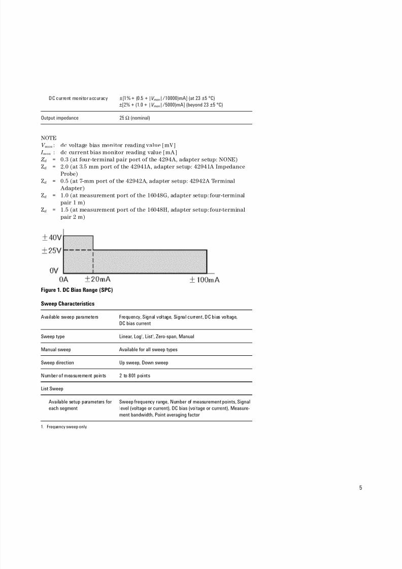
Figure 1. DC Bias Range (SPC)
Sweep Characteristics
Available sweep parameters Frequency, Signal voltage, Signal current, DC bias voltage,
DC bias current
Sweep type Linear, Log1, List1, Zero-span, Manual
Manual sweep Available for all sweep types
Sweep direction Up sweep, Down sweep
Number of measurement points 2 to 801 points
List Sweep
Available setup parameters for Sweep frequency range, Number of measurement points, Signal
each segment level (voltage or current), DC bias (voltage or current), Measure-
ment bandwidth, Point averaging factor
1. Frequency sweep only.
8/3/2019 5968-3809E (Agilent LCR Meter)
http://slidepdf.com/reader/full/5968-3809e-agilent-lcr-meter 6/32
6
Number of segments 1 to 18
Sweep span type Segment span or single span
Delay time
Type Point delay or sweep delay
Range 0 sec to 30 sec
Resolution 1 msec
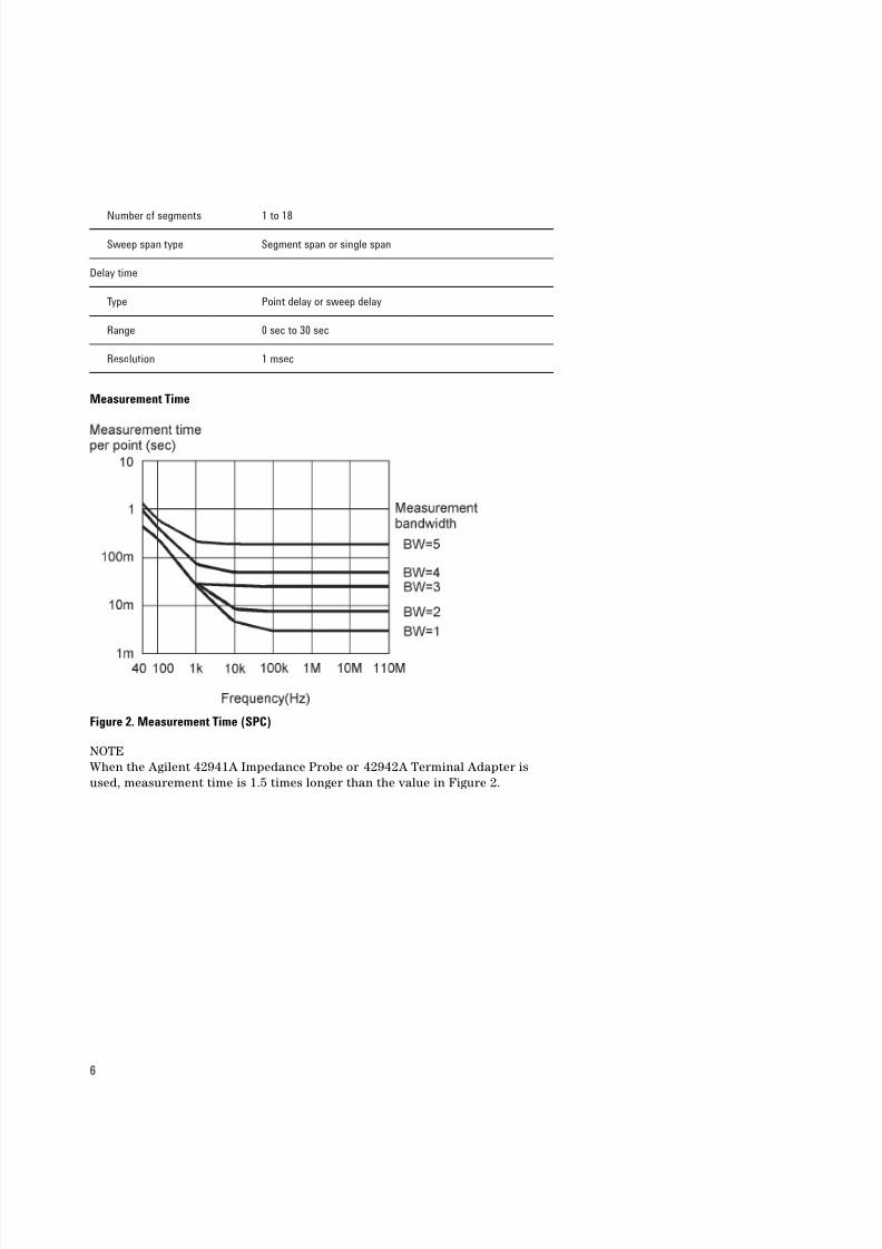
Measurement Time
Figure 2. Measurement Time (SPC)
NOTE
When the Agilent 42941A Impedance Probe or 42942A Terminal Adapter is
used, measurement time is 1.5 times longer than the value in Figure 2.
8/3/2019 5968-3809E (Agilent LCR Meter)
http://slidepdf.com/reader/full/5968-3809e-agilent-lcr-meter 7/32
7
Trigger Function
Trigger type Continuous, Single, Number of groups
Trigger source Internal (Free run), External (BNC connector input), GPIB or LAN,
Manual (Front key)
Trigger event type Point trigger, Sweep trigger
Measurement Bandwidth/Averaging
Measurement bandwidth
Range 1 (Fast) to 5 (Precise), 5 steps
Averaging
Type Sweep-to-sweep averaging, Point averaging
Averaging factor 1 to 256 (integer)
Adapter Setup
Adapter Selection
NONE No adapter (the 16047E, etc. direct connection type test fixture is
connected)
4TP 1M Four-terminal pair 1 m (16048G)
4TP 2M Four-terminal pair 2 m (16048H)
7-mm 42942A Terminal Adapter (42942A)
PROBE 42941A Impedance Probe (42941A)
Calibration
Calibration
User cal ibrat ion Cal ibrat ion performed with user-defined calibration kit (OPEN,
SHORT, LOAD)
Port extension Compensation performed when the measurement terminal isexpanded from the 7-mm connector of the 42942A Terminal
Adapter or the 3.5-mm connector of the 42941A Impedance
Probe. Enter electrical length or delay time for the extension.
Fixture compensation Compensation performed at the device contacts of the test fix-
ture using OPEN, SHORT, LOAD.
Calibration points Fixed points, or User points determined by sweep setups
8/3/2019 5968-3809E (Agilent LCR Meter)
http://slidepdf.com/reader/full/5968-3809e-agilent-lcr-meter 8/32
8
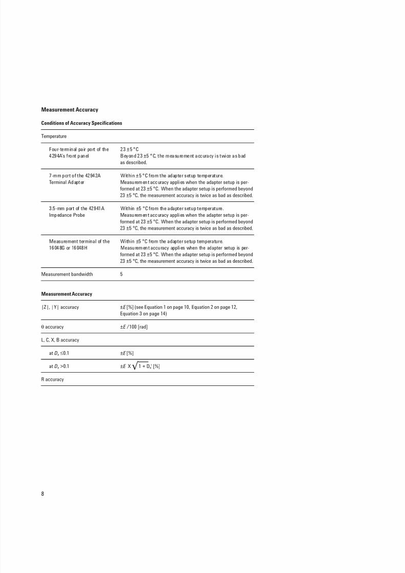
Measurement Accuracy
Conditions of Accuracy Specifications
Temperature
Four-terminal pair port of the 23 ±5 °C
4294A’s front panel Beyond 23 ±5 °C, the measurement accuracy is twice as bad
as described.
7-mm port of the 42942A Within ±5 °C from the adapter setup temperature.
Terminal Adapter Measurement accuracy applies when the adapter setup is per-
formed at 23 ±5 °C. When the adapter setup is performed beyond
23 ±5 °C, the measurement accuracy is twice as bad as described.
3.5-mm port of the 42941A Within ±5 °C from the adapter setup temperature.
Impedance Probe Measurement accuracy applies when the adapter setup is per-
formed at 23 ±5 °C. When the adapter setup is performed beyond
23 ±5 °C, the measurement accuracy is twice as bad as described.
Measurement terminal of the Within ±5 °C from the adapter setup temperature.
16048G or 16048H Measurement accuracy applies when the adapter setup is per-
formed at 23 ±5 °C. When the adapter setup is performed beyond
23 ±5 °C, the measurement accuracy is twice as bad as described.
Measurement bandwidth 5
Measurement Accuracy
|Z|, |Y| accuracy ±E [%] (see Equation 1 on page 10, Equation 2 on page 12,
Equation 3 on page 14)
θ accuracy ±E /100 [rad]
L, C, X, B accuracy
at D x ≤0.1 ±E [%]
at D x >0.1 ±E X 1 + Dx2 [%]
R accuracy
`b
8/3/2019 5968-3809E (Agilent LCR Meter)
http://slidepdf.com/reader/full/5968-3809e-agilent-lcr-meter 9/32
9
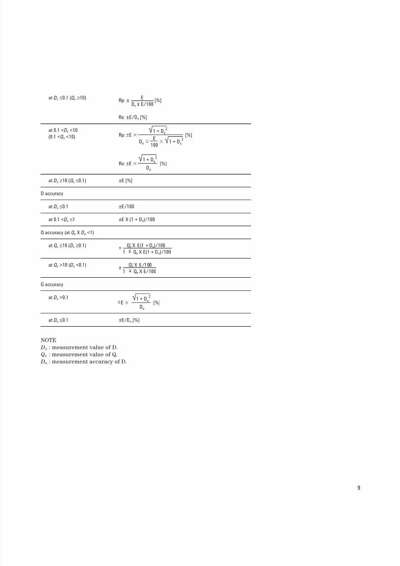
at D x ≤0.1 (Q x ≥10) ERp: ±Dx E/100
[%]
Rs: ±E/Dx [%]
at 0.1 <D x <10
(0.1 <Q x <10)
at D x ≥10 (Q x ≤0.1) ±E [%]
D accuracy
at D x ≤0.1 ±E/100
at 0.1 <D x ≤1 ±E X (1 + Dx)/100
Q accuracy (at Q x X Da <1)
at Q x ≤10 (D x ≥0.1) Qx2 X E(1 + Dx)/100
±1 Qx X E(1 + Dx)/100
at Q x >10 (D x <0.1) Qx2 X E/100
±1 Qx X E/100
G accuracy
at D x >0.1
at D x ≤0.1 ±E/Dx [%]
NOTE
D x : measurement value of D.
Q x : measurement value of Q.
Da : measurement accuracy of D.
±
±
Rp: ±E
Dx
[%]1 + Dx
2
1 + Dx2E
100
Rs: ±EDx
[%]1 + Dx
2
EDx
[%]1 + Dx2
±
8/3/2019 5968-3809E (Agilent LCR Meter)
http://slidepdf.com/reader/full/5968-3809e-agilent-lcr-meter 10/32
10
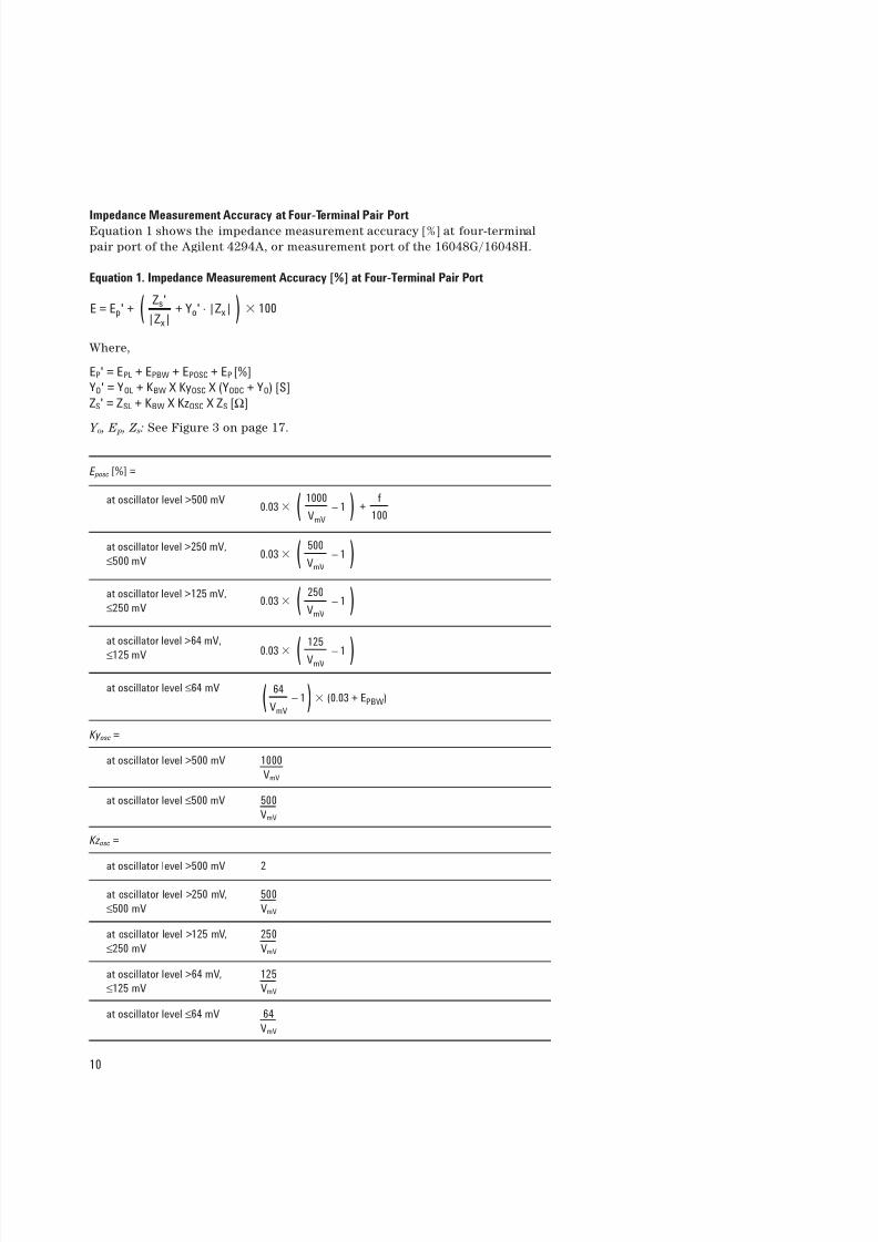
Impedance Measurement Accuracy at Four-Terminal Pair PortEquation 1 shows the impedance measurement accuracy [%] at four-terminal
pair port of the Agilent 4294A, or measurement port of the 16048G/16048H.
Equation 1. Impedance Measurement Accuracy [%] at Four-Terminal Pair Port
Where,
EP' = EPL + EPBW + EPOSC + EP [%]
YO' = YOL + KBW X KyOSC X (YODC + YO) [S]
ZS' = ZSL + KBW X KzOSC X ZS [Ω]
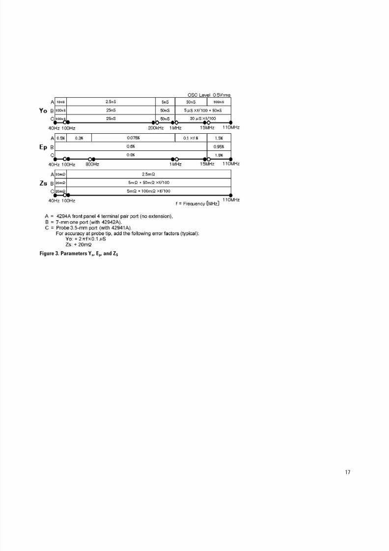
Y o , E p , Z s: See Figure 3 on page 17.
E posc [%] =
at oscillator level >500 mV
at oscillator level >250 mV,
≤500 mV
at oscillator level >125 mV,
≤250 mV
at oscillator level >64 mV,
≤125 mV
at oscillator level ≤64 mV
Ky osc =
at oscillator level >500 mV 1000
VmV
at oscillator level ≤500 mV 500
VmV
Kz osc =
at oscillator level >500 mV 2
at oscillator level >250 mV, 500
≤500 mV VmV
at oscillator level >125 mV, 250
≤250 mV VmV
at oscillator level >64 mV, 125
≤125 mV VmV
at oscillator level ≤64 mV 64
VmV
E = Ep' + ( Zs'+ Yo' . |Zx| ) 100
|Zx|
0.03 ( 1000 – 1 ) +
VmV
f
100
0.03 ( 500 – 1 )VmV
0.03 ( 250 – 1 )VmV
0.03
(125
– 1
)VmV
(0.03 + EPBW)( 64 – 1)VmV
8/3/2019 5968-3809E (Agilent LCR Meter)
http://slidepdf.com/reader/full/5968-3809e-agilent-lcr-meter 11/32
E PBW [%] =
at measurement BW = 5 0
at measurement BW = 4
frequency ≥50 kHz 0.03
frequency <50 kHz 0.06
at measurement BW = 3
frequency ≥50 kHz 0.1
frequency <50 kHz 0.2
at measurement BW = 2
frequency ≥50 kHz 0.2
frequency <50 kHz 0.4
at measurement BW = 1
frequency ≥50 kHz 0.4
frequency <50 kHz 0.8
K BW =
at measurement BW = 5 1
at measurement BW = 4 1
at measurement BW = 3
frequency ≤1 MHz 3
frequency >1 MHz 4
at measurement BW = 2
frequency ≤1 MHz 4
frequency >1 MHz 5
at measurement BW = 1
frequency ≤1 MHz 6
frequency >1 MHz 10
Y ODC =
at dc bias range = 1 mA 0 [S]
at dc bias range = 10 mA 1 [µS]
at dc bias range = 100 mA 10 [µS]
11

8/3/2019 5968-3809E (Agilent LCR Meter)
http://slidepdf.com/reader/full/5968-3809e-agilent-lcr-meter 12/32
12
E PL [%] =
when 16048G is used f0.02 + 2 X
100
when 16048H is used f0.02 + 3 X
100
Y OL =
when 16048G is used f500 X
100[nS]
when 16048H is used f1 X
100[µS]
Z SL =
when 16048G or 16048H is used
frequency ≥500 Hz 2 [mΩ]
frequency <500 Hz 5 [mΩ]
NOTE
SPC at frequency >10 MHz.
f : frequency in MHz.
V mV : oscillator level in mV
Impedance Measurement Accuracy at 7-mm Port of the Agilent 42942AEquation 2 shows the impedance measurement accuracy [%] at 7-mm port of
the 42942A Terminal Adapter.
Equation 2. Impedance Measurement Accuracy [%] at 7-mm Port of the Agilent 42942A
Where,
EP' = EPBW + EPOSC + EP [%]
YO' = KBW X KyOSC X (YODC + YO) [S]
ZS' = KBW X KzOSC X ZS [Ω]
Y o , E p , Z s: See Figure 3 on page 17.
E posc [%] =
at oscillator level >500 mV
at oscillator level >125 mV, 0
≤500 mV
E = Ep' + ( Zs'+ Yo' . |Zx| ) 100
|Zx|
( VmV – 1)500
f
100
8/3/2019 5968-3809E (Agilent LCR Meter)
http://slidepdf.com/reader/full/5968-3809e-agilent-lcr-meter 13/32
13
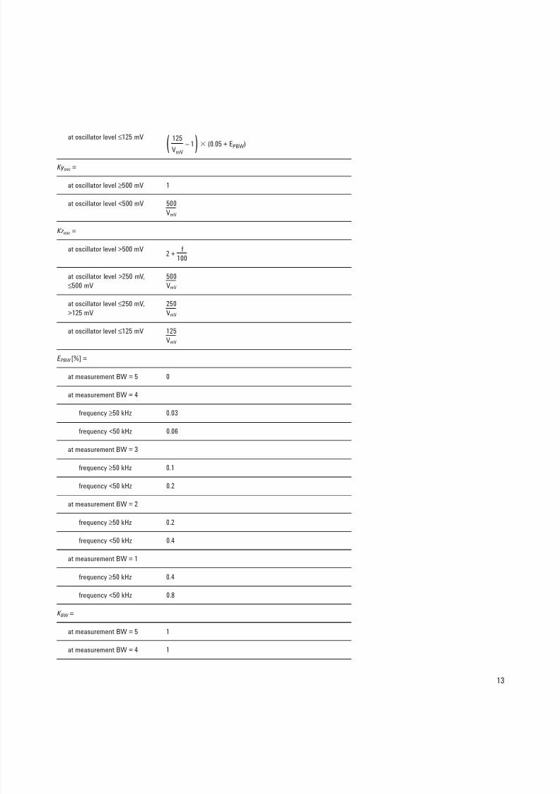
at oscillator level ≤125 mV
Ky osc =
at oscillator level ≥500 mV 1
at oscillator level <500 mV 500
VmV
Kz osc =
at oscillator level >500 mV2 +
f
100
at oscillator level >250 mV, 500≤500 mV VmV
at oscillator level ≤250 mV, 250
>125 mV VmV
at oscillator level ≤125 mV 125
VmV
E PBW [%] =
at measurement BW = 5 0
at measurement BW = 4
frequency ≥50 kHz 0.03
frequency <50 kHz 0.06
at measurement BW = 3
frequency ≥50 kHz 0.1
frequency <50 kHz 0.2
at measurement BW = 2
frequency ≥50 kHz 0.2
frequency <50 kHz 0.4
at measurement BW = 1
frequency ≥50 kHz 0.4
frequency <50 kHz 0.8
K BW =
at measurement BW = 5 1
at measurement BW = 4 1
(0.05 + EPBW)(125 – 1)VmV
8/3/2019 5968-3809E (Agilent LCR Meter)
http://slidepdf.com/reader/full/5968-3809e-agilent-lcr-meter 14/32
14
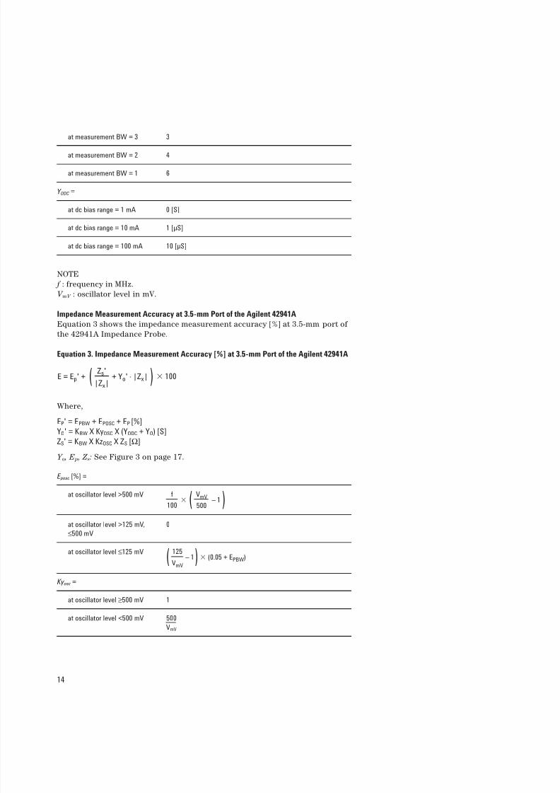
at measurement BW = 3 3
at measurement BW = 2 4
at measurement BW = 1 6
Y ODC =
at dc bias range = 1 mA 0 [S]
at dc bias range = 10 mA 1 [µS]
at dc bias range = 100 mA 10 [µS]
NOTE f : frequency in MHz.
V mV : oscillator level in mV.
Impedance Measurement Accuracy at 3.5-mm Port of the Agilent 42941A
Equation 3 shows the impedance measurement accuracy [%] at 3.5-mm port of
the 42941A Impedance Probe.
Equation 3. Impedance Measurement Accuracy [%] at 3.5-mm Port of the Agilent 42941A
Where,
EP' = EPBW + EPOSC + EP [%]
YO' = KBW X KyOSC X (YODC + YO) [S]
ZS' = KBW X KzOSC X ZS [Ω]
Y o , E p , Z s: See Figure 3 on page 17.
E posc [%] =
at oscillator level >500 mV
at oscillator level >125 mV, 0
≤500 mV
at oscillator level ≤125 mV
Ky osc =
at oscillator level ≥500 mV 1
at oscillator level <500 mV 500
VmV
E = Ep' + ( Zs'+ Yo' . |Zx| ) 100
|Zx|
( VmV – 1)500
f
100
(0.05 + EPBW)
(125
– 1
)VmV
8/3/2019 5968-3809E (Agilent LCR Meter)
http://slidepdf.com/reader/full/5968-3809e-agilent-lcr-meter 15/32
15
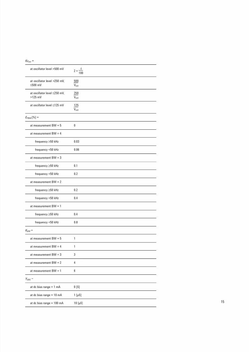
Kz osc =
at oscillator level >500 mV2 +
f
100
at oscillator level >250 mV, 500
≤500 mV VmV
at oscillator level ≤250 mV, 250
>125 mV VmV
at oscillator level ≤125 mV 125
VmV
E PBW [%] =
at measurement BW = 5 0
at measurement BW = 4
frequency ≥50 kHz 0.03
frequency <50 kHz 0.06
at measurement BW = 3
frequency ≥50 kHz 0.1
frequency <50 kHz 0.2
at measurement BW = 2
frequency ≥50 kHz 0.2
frequency <50 kHz 0.4
at measurement BW = 1
frequency ≥50 kHz 0.4
frequency <50 kHz 0.8
K BW =
at measurement BW = 5 1
at measurement BW = 4 1
at measurement BW = 3 3
at measurement BW = 2 4
at measurement BW = 1 6
Y ODC =
at dc bias range = 1 mA 0 [S]
at dc bias range = 10 mA 1 [µS]
at dc bias range = 100 mA 10 [µS]
8/3/2019 5968-3809E (Agilent LCR Meter)
http://slidepdf.com/reader/full/5968-3809e-agilent-lcr-meter 16/32
16
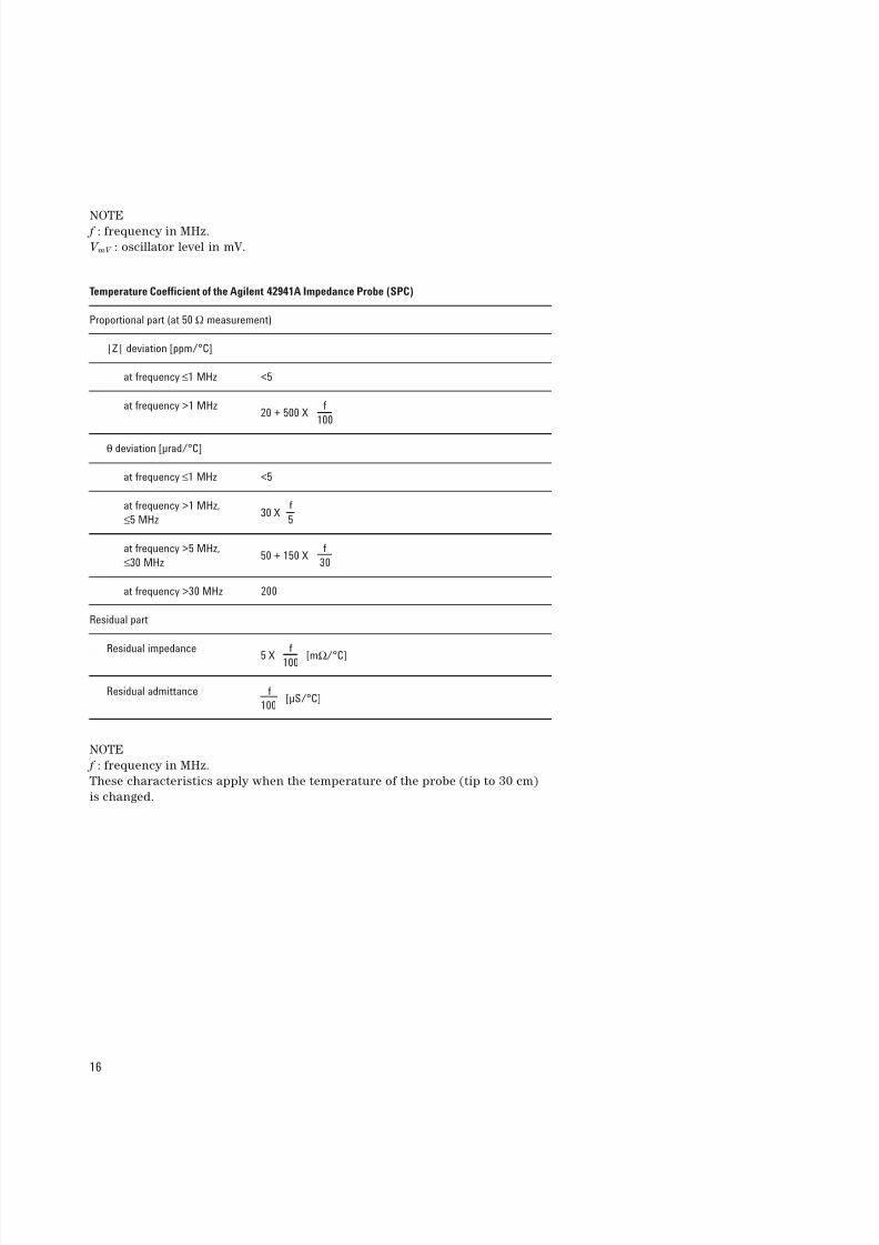
NOTE f : frequency in MHz.
V mV : oscillator level in mV.
Temperature Coefficient of the Agilent 42941A Impedance Probe (SPC)
Proportional part (at 50 Ω measurement)
|Z| deviation [ppm/°C]
at frequency ≤1 MHz <5
at frequency >1 MHz20 + 500 X
f
100
θ deviation [µrad/°C]
at frequency ≤1 MHz <5
at frequency >1 MHz,30 X
f
≤5 MHz 5
at frequency >5 MHz,50 + 150 X
f
≤30 MHz 30
at frequency >30 MHz 200
Residual part
Residual impedance5 X
f[mΩ/°C]100
Residual admittance f[µS/°C]
100
NOTE
f : frequency in MHz.
These characteristics apply when the temperature of the probe (tip to 30 cm)
is changed.
8/3/2019 5968-3809E (Agilent LCR Meter)
http://slidepdf.com/reader/full/5968-3809e-agilent-lcr-meter 17/32
17
Figure 3. Parameters Yo, Ep, and ZS
8/3/2019 5968-3809E (Agilent LCR Meter)
http://slidepdf.com/reader/full/5968-3809e-agilent-lcr-meter 18/32
18
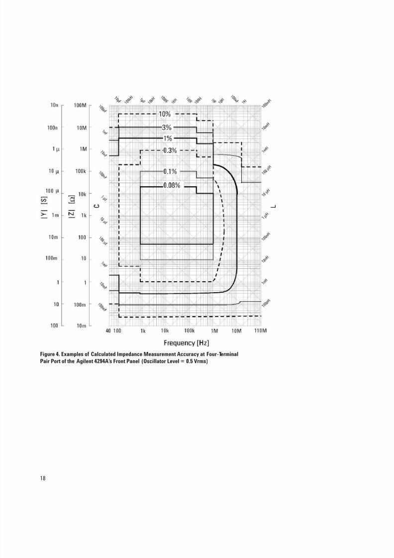
Figure 4. Examples of Calculated Impedance Measurement Accuracy at Four-Terminal
Pair Port of the Agilent 4294A’s Front Panel (Oscillator Level = 0.5 Vrms)

8/3/2019 5968-3809E (Agilent LCR Meter)
http://slidepdf.com/reader/full/5968-3809e-agilent-lcr-meter 19/32
19
Figure 5. Impedance Measurement Accuracy at 7-mm Port of the Agilent 42942A Terminal
Adapter Connected to the Agilent 4294A (Oscillator Level = 0.5 Vrms)
8/3/2019 5968-3809E (Agilent LCR Meter)
http://slidepdf.com/reader/full/5968-3809e-agilent-lcr-meter 20/32
20
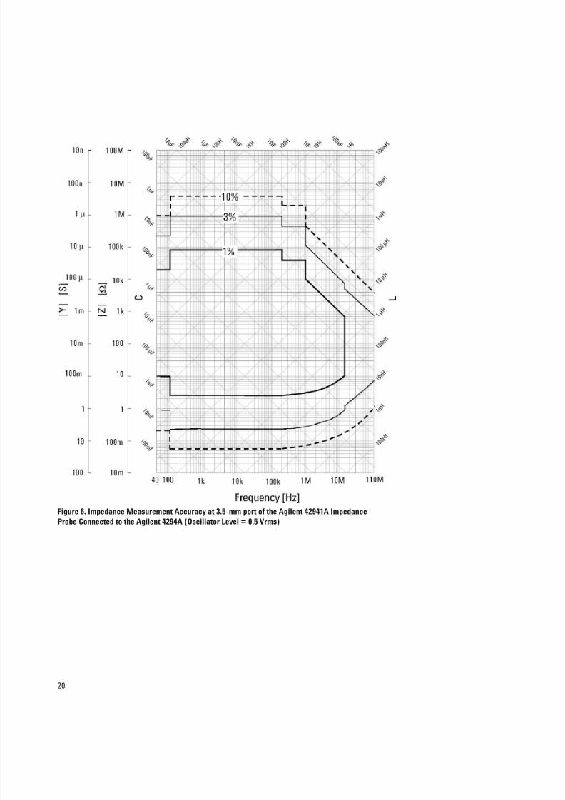
Figure 6. Impedance Measurement Accuracy at 3.5-mm port of the Agilent 42941A Impedance
Probe Connected to the Agilent 4294A (Oscillator Level = 0.5 Vrms)
8/3/2019 5968-3809E (Agilent LCR Meter)
http://slidepdf.com/reader/full/5968-3809e-agilent-lcr-meter 21/32
21
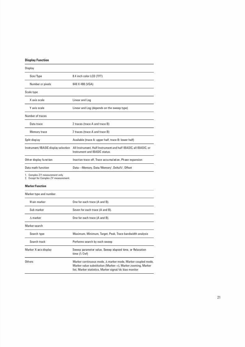
Display Function
Display
Size/Type 8.4 inch color LCD (TFT)
Number or pixels 640 X 480 (VGA)
Scale type
X axis scale Linear and Log
Y axis scale Linear and Log (depends on the sweep type)
Number of traces
Data trace 2 traces (trace A and trace B)
Memory trace 2 traces (trace A and trace B)
Split display Available (trace A: upper half, trace B: lower half)
Instrument/IBASIC display selection All Instrument, Half Instrument and half IBASIC, all IBASIC, or
Instrument and IBASIC status.
Other display funct ion Inact ive trace off , Trace accumulation, Phase expansion
Data math function Data—Memory, Data/Memory1, Delta%2, Offset
1. Complex Z-Y measurement only.2. Except for Complex Z-Y measurement.
Marker Function
Marker type and number
Main marker One for each trace (A and B).
Sub marker Seven for each trace (A and B).
∆ marker One for each trace (A and B).
Marker search
Search type Maximum, Minimum, Target, Peak, Trace bandwidth analysis
Search track Performs search by each sweep
Marker X-axis display Sweep parameter value, Sweep elapsed time, or Relaxation
time (1/2πf)
Others Marker continuous mode, ∆ marker mode, Marker coupled mode,
Marker value substitution (Marker→), Marker zooming, Marker
list, Marker statistics, Marker signal/dc bias monitor
8/3/2019 5968-3809E (Agilent LCR Meter)
http://slidepdf.com/reader/full/5968-3809e-agilent-lcr-meter 22/32
22
Equivalent Circuit Analysis
Circuit model 3 component model (4 models), 4 component model (1 model)
Analysis type Equivalent circuit parameters calculation, Frequency characteris-
tics simulation
Limit Line Test
Available setup parameters for each Sweep start value, sweep stop value, upper limit (middle value)
segment and lower limit (delta limit) for sweep start, upper limit
(middle value) and lower limit (delta limit) for sweep stop
Number of segments 1 to 18
Other functions Beep fail, Limit line offset
Mass Storage
Flexible disk drive
Type 3.5 inch, Built-in
Size 1.44 MB
Format DOS
Formatting Available
Volatile memory disk
Size 512 KB
Non-volatile memory disk (Flash memory)
Size 10 MB
Stored data State (binary), Data (binary or ASCII), Display graphics (TIFF)
Printer Parallel Port
Interface Standard IEEE 1284 Centronics
Printer control language HP PCL3 printer control language
Connector type 25 pin D-SUB connector
8/3/2019 5968-3809E (Agilent LCR Meter)
http://slidepdf.com/reader/full/5968-3809e-agilent-lcr-meter 23/32
23
GPIB
Standard conformity IEEE 448.1-1987, IEEE 488.2-1987, IEC 625, JIS C ,1901-1987
Available functions (function code)1 SH1, AH1, T6, TE0, L4, LE0, SR1, RL1, PP0, DC1, DT1, C1, C2, C3,
C4, C11, E2
Numeric data transfer format ASCII, 32 or 64 bit IEEE 754 floating point format, DOS PC format
(32 bit IEEE reversed byte order)
1. See document of the standard for the meaning of each code.
Instrument BASIC
Keyboard
Type PS/2 style 101 English
Connector Type Mini-DIN connector
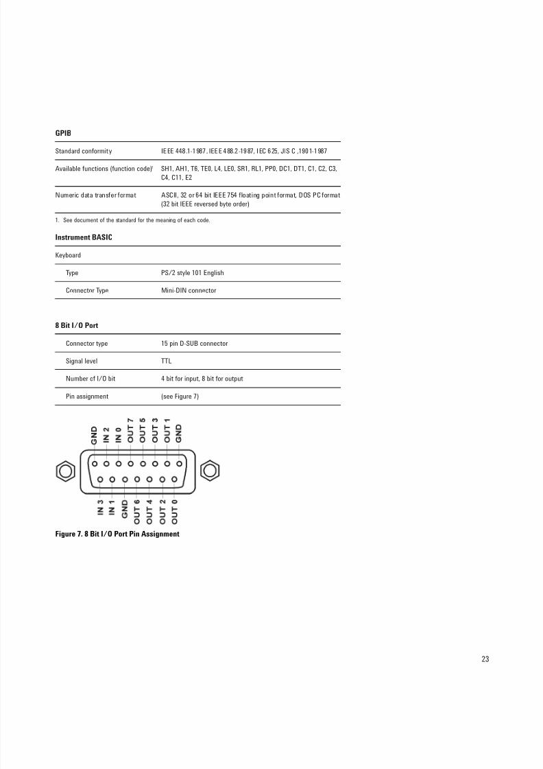
8 Bit I/O Port
Connector type 15 pin D-SUB connector
Signal level TTL
Number of I/O bit 4 bit for input, 8 bit for output
Pin assignment (see Figure 7)
Figure 7. 8 Bit I/O Port Pin Assignment
8/3/2019 5968-3809E (Agilent LCR Meter)
http://slidepdf.com/reader/full/5968-3809e-agilent-lcr-meter 24/32
24
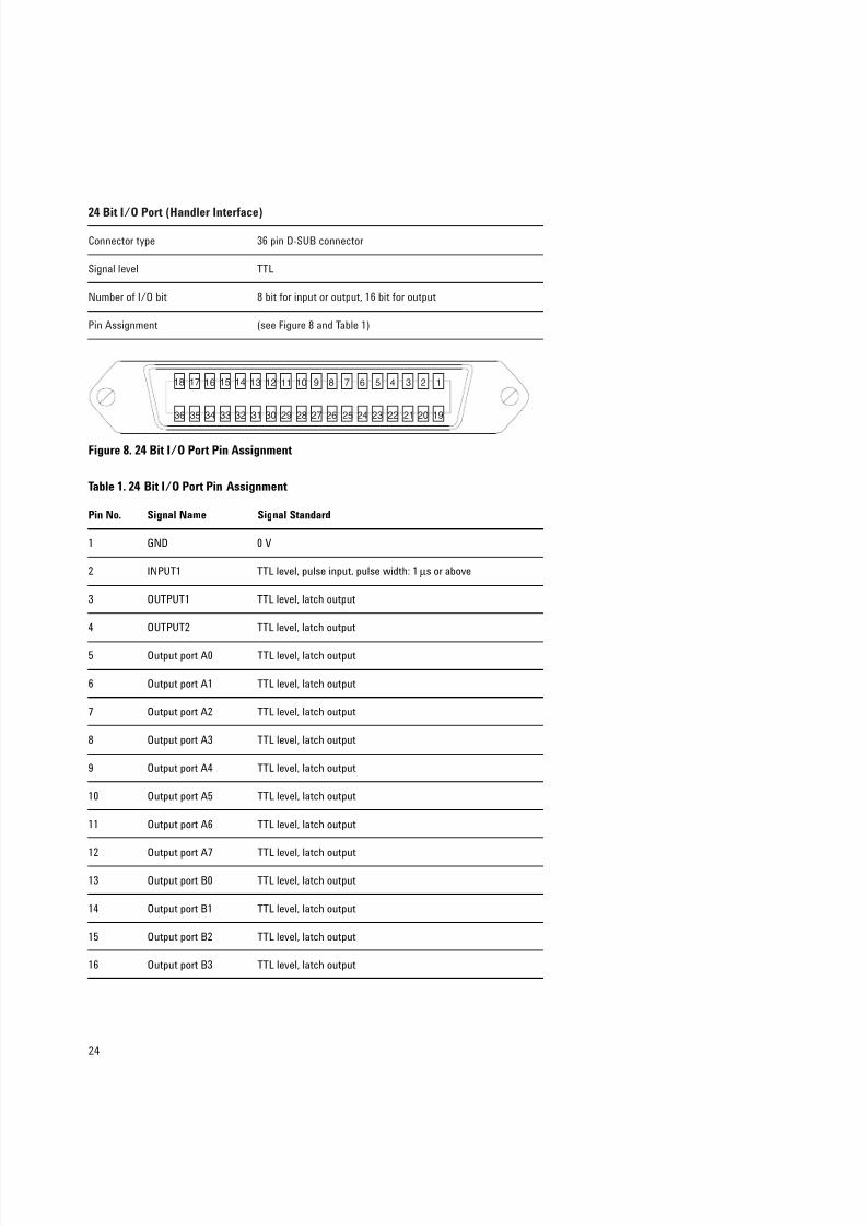
24 Bit I/O Port (Handler Interface)
Connector type 36 pin D-SUB connector
Signal level TTL
Number of I/O bit 8 bit for input or output, 16 bit for output
Pin Assignment (see Figure 8 and Table 1)
123456789101112131415161718
192021222324252627282930313233343536
Table 1. 24 Bit I/O Port Pin Assignment
Pin No. Signal Name Signal Standard
1 GND 0 V
2 INPUT1 TTL level, pulse input, pulse width: 1 µs or above
3 OUTPUT1 TTL level, latch output
4 OUTPUT2 TTL level, latch output
5 Output port A0 TTL level, latch output
6 Output port A1 TTL level, latch output
7 Output port A2 TTL level, latch output
8 Output port A3 TTL level, latch output
9 Output port A4 TTL level, latch output
10 Output port A5 TTL level, latch output
11 Output port A6 TTL level, latch output
12 Output port A7 TTL level, latch output
13 Output port B0 TTL level, latch output
14 Output port B1 TTL level, latch output
15 Output port B2 TTL level, latch output
16 Output port B3 TTL level, latch output
Figure 8. 24 Bit I/O Port Pin Assignment
8/3/2019 5968-3809E (Agilent LCR Meter)
http://slidepdf.com/reader/full/5968-3809e-agilent-lcr-meter 25/32
25
Table 1. 24 Bit I/0 Port Pin Assignment
Pin No. Signal Name Signal Standard
17 Output port B4 TTL level, latch output
18 Output port B5 TTL level, latch output
19 Output port B6 TTL level, latch output
20 Output port B7 TTL level, latch output
21 Input/Output port C0 TTL level, latch output
22 Input/Output port C1 TTL level, latch output
23 Input/Output port C2 TTL level, latch output
24 Input/Output port C3 TTL level, latch output
25 Input/Output port D0 TTL level, latch output
26 Input/Output port D1 TTL level, latch output
27 Input/Output port D2 TTL level, latch output
28 Input/Output port D3 TTL level, latch output
29 Port C status TTL level, input mode; LOW, output mode: HIGH
30 Port D status TTL level, input mode; LOW, output mode: HIGH
31 Write strobe signal TTL level, active low, pulse output (width: 10 µs, typical)
32 +5 V pullup
33 SWEEP END signal TTL level, active low, pulse output (width: 20 µs, typical)
34 +5 V +5 V, 100 mA MAX
35 PASS/FAIL signal TTL level, PASS: HIGH, FAIL; LOW, latch output
36 PASS/FAIL write TTL level, active low, pulse output (width: 10 µs, typical)
strobe signal
LAN Interface
Standard conformity 10 Base-T Ethertwist, RJ45 connector
Protocol TCP/IP
Supported application Telnet, FTP, FTP with automatic execution
8/3/2019 5968-3809E (Agilent LCR Meter)
http://slidepdf.com/reader/full/5968-3809e-agilent-lcr-meter 26/32
26
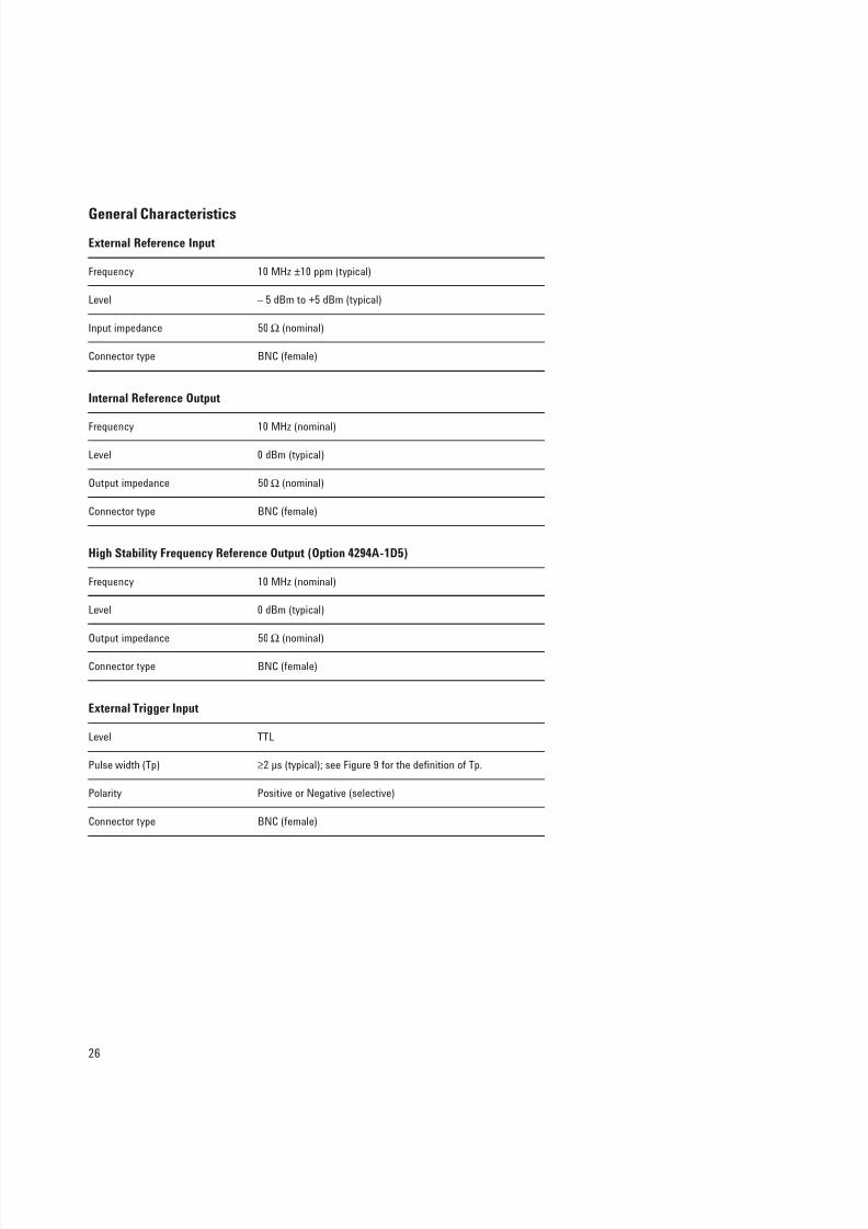
General Characteristics
External Reference Input
Frequency 10 MHz ±10 ppm (typical)
Level – 5 dBm to +5 dBm (typical)
Input impedance 50 Ω (nominal)
Connector type BNC (female)
Internal Reference Output
Frequency 10 MHz (nominal)
Level 0 dBm (typical)
Output impedance 50 Ω (nominal)
Connector type BNC (female)
High Stability Frequency Reference Output (Option 4294A-1D5)
Frequency 10 MHz (nominal)
Level 0 dBm (typical)
Output impedance 50 Ω (nominal)
Connector type BNC (female)
External Trigger Input
Level TTL
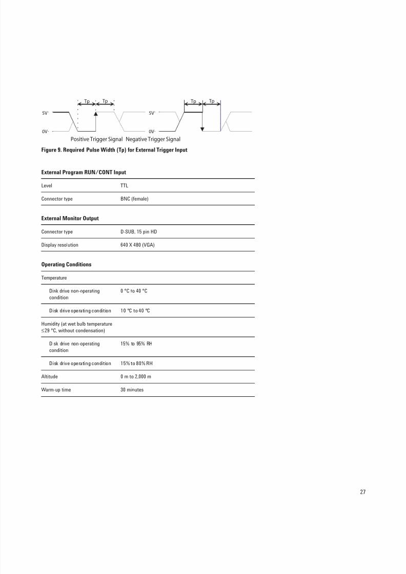
Pulse width (Tp) ≥2 µs (typical); see Figure 9 for the definition of Tp.
Polarity Positive or Negative (selective)
Connector type BNC (female)
8/3/2019 5968-3809E (Agilent LCR Meter)
http://slidepdf.com/reader/full/5968-3809e-agilent-lcr-meter 27/32
27
Figure 9. Required Pulse Width (Tp) for External Trigger Input
External Program RUN/CONT Input
Level TTL
Connector type BNC (female)
External Monitor Output
Connector type D-SUB, 15 pin HD
Display resolution 640 X 480 (VGA)
Operating Conditions
Temperature
Disk drive non-operating 0 °C to 40 °C
condition
Disk drive operating condition 10 °C to 40 °C
Humidity (at wet bulb temperature
≤29 °C, without condensation)
Disk drive non-operating 15% to 95% RH
condition
Disk drive operating condition 15% to 80% RH
Altitude 0 m to 2,000 m
Warm-up time 30 minutes
Tp Tp Tp Tp
5V
0V
5V
0V
Positive Trigger Signal Negative Trigger Signal
8/3/2019 5968-3809E (Agilent LCR Meter)
http://slidepdf.com/reader/full/5968-3809e-agilent-lcr-meter 28/32
28
Non-operating Conditions
Temperature –20 °C to +60 °C
Humidity (at wet bulb temperature 15% to 95% RH
≤45 °C, without condensation)
Altitude 0 m to 4,572 m
Others
EMC EN 55011(1991)/CISPR 11(1990) Group 1, Class A
EN 50082-1(1992)/IEC 61000-4-2(1995) 4 kV CD, 8 kV AD
EN 50082-1(1992)/IEC 61000-4-3(1995) 3 V/m, 27 MHz to 1 GHz
EN 50082-1(1992)/IEC 61000-4-4(1995) 0,5 kV Signal Line, 1 kV
Power Line
EN 61000-3-2(1995)/IEC 61000-3-2(1995)
EN 61000-3-3(1995)/IEC 61000-3-3(1994)z
Safety EN 61010-1(1993) +Amd2(1995)/IEC61010-1(1990)
+Am1(1992) +Am2(1995)
CSA-C22.2 N0.1010.1-92
Power requirement 90 V to 132 V, or 198 V to 264 V (automatically switched),
47 Hz to 63 Hz, 300 VA max.
Weight 25 kg (SPC)
Dimensions See Figures 10 through 12.
8/3/2019 5968-3809E (Agilent LCR Meter)
http://slidepdf.com/reader/full/5968-3809e-agilent-lcr-meter 29/32
29
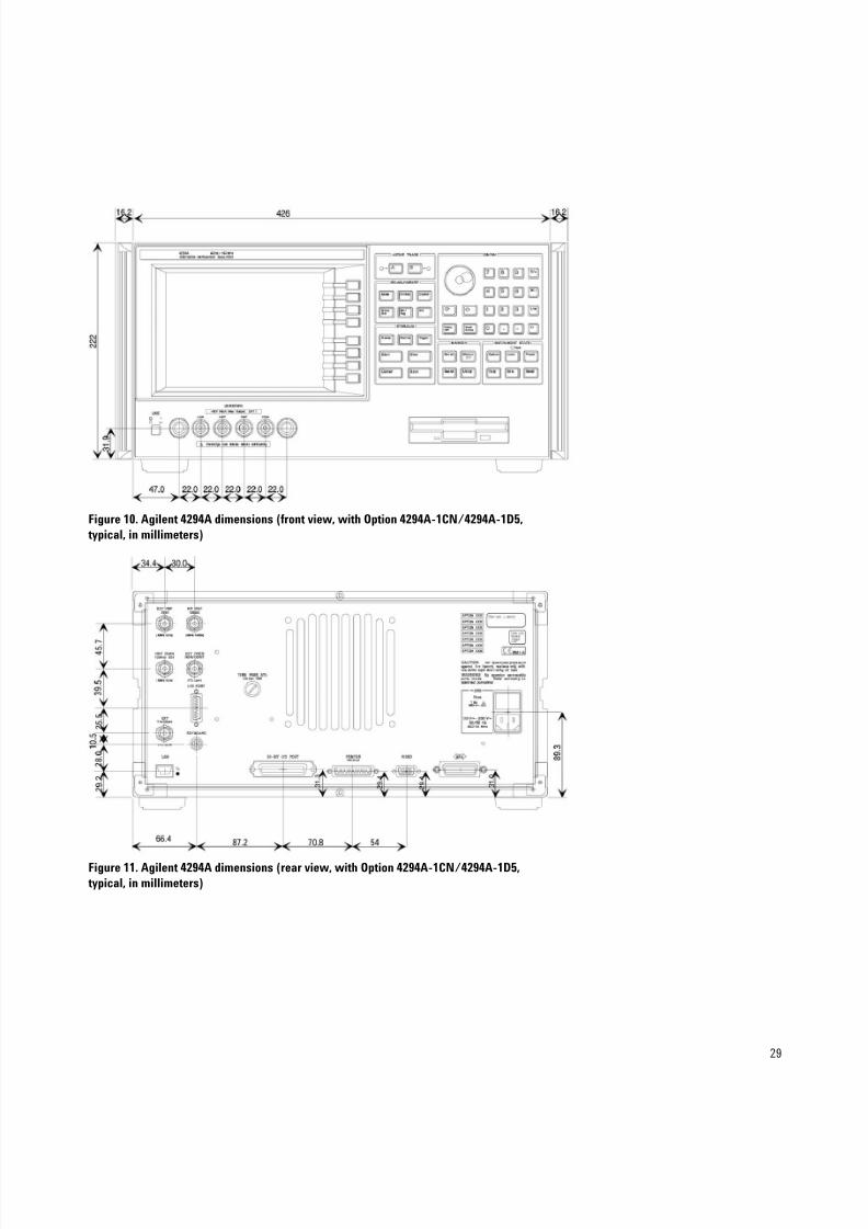
Figure 10. Agilent 4294A dimensions (front view, with Option 4294A-1CN/4294A-1D5,
typical, in millimeters)
Figure 11. Agilent 4294A dimensions (rear view, with Option 4294A-1CN/4294A-1D5,
typical, in millimeters)
8/3/2019 5968-3809E (Agilent LCR Meter)
http://slidepdf.com/reader/full/5968-3809e-agilent-lcr-meter 30/32
30
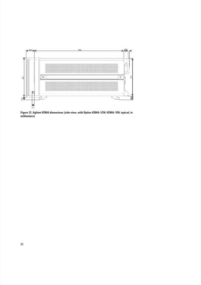
Figure 12. Agilent 4294A dimensions (side view, with Option 4294A-1CN/4294A-1D5, typical, in
millimeters)
46.0
11.1
23.4502
2 2 1
1 3 . 1
2 1 1
1
9 . 8
8/3/2019 5968-3809E (Agilent LCR Meter)
http://slidepdf.com/reader/full/5968-3809e-agilent-lcr-meter 31/32
31
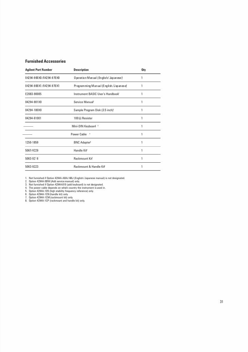
Furnished Accessories
Agilent Part Number Description Qty
04294-900X0/04294-970X0 Operation Manual (English/Japanese)1 1
04294-900X1/04294-970X1 Programming Manual (English/Japanese)1 1
E2083-90005 Instrument BASIC User’s Handbook1 1
04294-901X0 Service Manual2 1
04294-180X0 Sample Program Disk (3.5 inch)1 1
04294-61001 100 Ω Resister 1
——— Mini-DIN Keyboard 3 1
——— Power Cable 4 1
1250-1859 BNC Adapter5 1
5063-9229 Handle Kit6 1
5063-9216 Rackmount Kit7 1
5063-9223 Rackmount & Handle Kit8 1
1. Not furnished if Option 4294A-ABA/ABJ (English/Japanese manual) is not designated.2. Option 4294A-0BW (Add service manual) only.
3. Not furnished if Option 4294A-810 (add keyboard) is not designated.4. The power cable depends on which country the instrument is used in.5. Option 4294A-1D5 (high stability frequency reference) only.6. Option 4294A-1CN (handle kit) only.7. Option 4294A-1CM (rackmount kit) only.8. Option 4294A-1CP (rackmount and handle kit) only.
8/3/2019 5968-3809E (Agilent LCR Meter)
http://slidepdf.com/reader/full/5968-3809e-agilent-lcr-meter 32/32
www.agilent.com/find/emailupdates
Get the latest information on the productsand applications you select.
www.agilent.com/find/agilentdirect
Quickly choose and use your test
equipment solutions with confidence.
Agilent Email Updates
Agilent Direct
Remove all doubt
Our repair and calibration services will get
your equipment back to you, performing
like new, when promised. You will get
full value out of your Agilent equipment
throughout its lifetime. Your equipment
will be serviced by Agilent-trained techni-
cians using the latest factory calibration
procedures, automated repair diagnostics
and genuine parts. You will always have the
utmost confidence in your measurements.
Agilent offers a wide range of additional
expert test and measurement services for
your equipment, including initial start-up
assistance onsite education and training,
as well as design, system integration, and
project management.
For more information on repair and
calibration services, go to
www.agilent.com/find/removealldoubt
www.agilent.com
For more information on Agilent Technolo-
gies’ products, applications
or services, please contact your local
Agilent office. The complete list is
available at:
www.agilent.com/find/contactus
Americas
Canada (877) 894-4414
Latin America 305 269 7500
United States (800) 829-4444
Asia Pacific
Australia 1 800 629 485
China 800 810 0189
Hong Kong 800 938 693
India 1 800 112 929
Japan 0120 (421) 345
Korea 080 769 0800
Malaysia 1 800 888 848Singapore 1 800 375 8100
Taiwan 0800 047 866
Thailand 1 800 226 008
Europe & Middle East
Austria 0820 87 44 11
Belgium 32 (0)2 404 93 40
Denmark 45 70 13 15 15
Finland 358 (0)10 855 2100
France 0825 010 700*
*0.125 ¤/minute
Germany 01805 24 6333**
**0.14 ¤/minute
Ireland 1890 924 204
Israel 972-3-9288-504/544
Italy 39 02 92 60 8484
Netherlands 31 (0)20 547 2111
Spain 34 (91)631 3300
Sweden 0200-88 22 55
Switzerland 0800 80 53 53
United Kingdom 44 (0)118 9276201
Other European Countries:
www.agilent.com/find/contactusRevised: March 27, 2008
Product specifications and descriptions in
this document subject to change
without notice.
© Agilent Technologies, Inc., 1999, 2000,2002, 2003, 2008Printed in USA, April 10, 20085968-3809E
Web Resource
www.agilent.com/find/impedance


![Agilent ESAシリーズ・ スペクトラム・アナライザ セルフデ …literature.cdn.keysight.com/litweb/pdf/5968-3658JA.pdfします(図4)。[Marker→]{Mkr→CF Step}](https://img.dokumen.tips/doc/110x75/5f9e04ee0419da32c2250596/agilent-esafff-fffffff-fff-i4imarkeraimkracf.jpg)