Embed Size (px)
Citation preview

Please file in Service Binder5672 437 - 04 06/2016
Vitogate 300
Installation and Service Instructionsfor use by heating contractor
Communication with heating systems via BACnet or Modbus
Product may not be exactly as shown
Read and save these instructionsfor future reference.
IMPORTANT
Certified as a component part for Viessmann boilers

2
5672 4
37 -
04
Vitogate 300 Installation and Service
Safety, Installation and Warranty Requirements
Please ensure that these instructions are read and understood before commencing installation. Failure to comply with the instructions listed below and details printed in this manual can cause product/property damage, severe personal injury, and/or loss of life. Ensure all requirements below are understood and fulfilled (including detailed information found in manual subsections).
Product documentation Read all applicable documentation before commencing installation. Store documentation near boiler in a readily accessible location for reference in the future by service personnel.
For a listing of applicable literature, please see section entitled “Important Regulatory and Safety Requirements”.
Licensed professional heating contractor The installation, adjustment, service and maintenance of this equipment must be performed by a licensed professional heating contractor.
Please see section entitled Safety and “Important Regulatory and Installation Requirements”.
Advice to owner Once the installation work is complete, the heating contractor must familiarize the system operator/ ultimate owner with all equipment, as well as safety precautions/requirements, shutdown procedure, and the need for professional service annually before the heating season begins.
Safety
Warranty Information contained in this and related product documentation must be read and followed. Failure to do so renders the warranty null and void.
2
Safety, Installation and Warranty Requirements

3
5672 4
37 -
04
Vitogate 300 Installation and Service
3
Safety
General Information
Installation
Connections
Commissioning
Parts
Specifications
Safety, Installation and Warranty Requirements..............2 Product documentation...........................................2 Licensed professional heating contractor...................2 Advice to owner....................................................2 Warranty...............................................................2
Important Regulatory and Installation Requirements........4 Approvals.............................................................4 Codes..................................................................4 Working on the equipment......................................4 Power supply........................................................4
About these Installation Instructions..............................4
Preparing for Installation................................................5Wall Mounting (with enclosure)...................................6Power Supply Connections for Wall Mounting (with enclosure).........................................................7CM2 Junction Box DIN Rail Mounting............................8Power Supply Connections for CM2 Junction Box..........9Vitogate and Power Supply Location for CA3..............10Power Supply Connections for CA3............................11
Power Supply...........................................................12Connection Diagram..................................................12Making the LON Connection.......................................13
Integrating the Vitotronic Unit into LON.......................14Updating LON Participant List...................................14Carrying out Participant Check..................................14Commissioning.........................................................15
Parts List.................................................................16
Vitogate 300, Type BN/MB.......................................17Power Supply Unit....................................................17
Page
Table of Contents
Page

4
5672 4
37 -
04
Vitogate 300 Installation and ServiceGeneral Information
Important Regulatory and Installation Requirements
ApprovalsViessmann boilers, burners and controls are approved for sale in North America by CSA International.
CodesThe installation of this unit shall be in accordance with local codes. In the absence of local codes, use: - CSA C22.1 Part 1 and/or local codes in Canada- National Electrical Code ANSI/NFPA 70 in the U.S.Always use latest editions of codes.The heating contractor must comply with the Standard for Controls and Safety Devices for Automatically Fired Boilers, ANSI/ASME CSD-1 where required by the authority having jurisdiction.
Working on the equipmentThe installation, adjustment, service, and maintenance of this product must be done by a licensed professional heating contractor who is qualified and experienced in the installation, service, and maintenance of hot water boilers. There are no user serviceable parts on the boiler, burner, or control.
Power supplyInstall power supply in accordance with the regulations of the authorities having jurisdiction or, in absence of such requirements, in accordance with National Codes. Viessmann recommends the installation of a disconnect switch to the 120V power supply outside of the boiler room.Ensure main power supply to equipment, the heating system, and all external controls have been deactivated. Close main oil or gas supply valve. Take precautions in both instances to avoid accidental activation of power during service work.
Please carefully read this manual prior to attempting installation. Any warranty is null and void if these instructions are not followed.
For information regarding other Viessmann System Technology componentry, please reference documentation of the respective product.
We offer frequent installation and service seminars to familiarize our partners with our products. Please inquire.
The completeness and functionality of field supplied electrical controls and components must be verified by the heating contractor. These include low water cut-offs, flow switches (if used), staging controls, pumps, motorized valves, air vents, thermostats, etc.
WARNINGTurn off electric power supply before servicing. Contact with live electric components can cause shock or loss of life.
About these Installation Instructions
Take note of all symbols and notations intended to draw attention to potential hazards or important product information.
CAUTIONCautions draw your attention to the presence of potential hazards or important product information.
WARNINGWarnings draw your attention to the presence of potential hazards or important product information.
IMPORTANT
Indicates an imminently hazardous situation which, if not avoided, could result in death, serious injury or substantial product/property damage.
Indicates an imminently hazardous situation which, if not avoided, may result in minor injury or product / property damage.
Helpful hints for installation, operation or maintenance which pertain to the product.
This symbol indicates to note additional information
This symbol indicates that other instructions must be referenced.

5
5672 4
37 -
04
Vitogate 300 Installation and Service Installation
Preparing for Installation
Product informationThe Vitogate 300, type BN/MB gateway is designed to integrate the Vitotronic control units using the integral LON communication module (accessory*) to BACnet or Modbus control systems. For supported appliances/devices and further information, see www.vitogate.info.The Vitogate 300, type BN/MB must be integrated into the BACnet or Modbus control system by an authorized contractor.* Depending on the relevant control, this may be an additional accessory item.
FunctionsThe Vitogate 300, type BN/MB enables system users to utilize the following functions in conjunction with a BACnet or Modbus control system:
H Adjustment of the heating system operating states (standby/heating mode)
H Setting heating system parameters (temperature setpoint)
H Relaying fault and error messages
Intended useInstall and operate Vitogate products as intended in conjunction with the electronic control units and controllers for the Viessmann heat and power generatorsdesigned for this system, giving due consideration to the associated installation, service and operating instructions. In particular, observe the current and voltage specifications for connections and hook-ups.Use of the Vitogate products are exclusively for monitoring, operating and optimizing systems with the user and communication interfaces specified for this purpose in the relevant printed documentation. In the case of communication interfaces, ensure on site that the system requirements specified in the product documentation are met at all times for every transfer medium employed. Only use the specified components for the mains power supply (e.g. mains power adaptors).
Vitogate 300, type BN/MB and its power supply unit are suitable for mounting on a DIN rail (TS35 Top Hat Rail 35 mm x 15 mm or 35 mm x 7.5 mm).
Legend A Power supply unitB Vitogate 300

6
5672 4
37 -
04
Vitogate 300 Installation and ServiceInstallation
Wall Mounting (with enclosure)
Legend A Module enclosure (complete with a Vitogate 300 and power supply unit)B Enclosure coverC Wall anchors (field supplied)D Mounting screws (field supplied)
7
5672 4
37 -
04
Vitogate 300 Installation and Service Installation
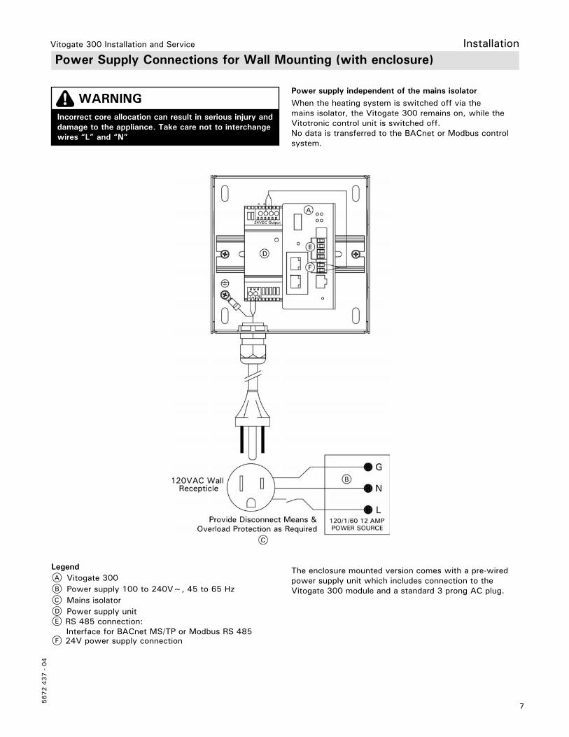
Power Supply Connections for Wall Mounting (with enclosure)
Power supply independent of the mains isolatorWhen the heating system is switched off via the mains isolator, the Vitogate 300 remains on, while the Vitotronic control unit is switched off.No data is transferred to the BACnet or Modbus control system.
WARNINGIncorrect core allocation can result in serious injury and damage to the appliance. Take care not to interchangewires “L” and “N”
Legend A Vitogate 300B Power supply 100 to 240V~, 45 to 65 HzC Mains isolatorD Power supply unitE RS 485 connection: Interface for BACnet MS/TP or Modbus RS 485F 24V power supply connection
The enclosure mounted version comes with a pre-wired power supply unit which includes connection to the Vitogate 300 module and a standard 3 prong AC plug.

8
5672 4
37 -
04
Vitogate 300 Installation and ServiceInstallation
CM2 Junction Box DIN Rail Mounting
1. Measure to allow for clearances as shown, than use the DIN rail as a template to mark and centre punch hole locations.
2. Drill two holes 3/16 in.
3. Mount the DIN rail A with the mounting hardware to the inside of the junction box as shown.
4. Mount the Vitogate 300 C to junction box side DIN rail A and mount the power supply unit B to the junction box main DIN rail D.
Legend A Junction box side DIN rail 3 in. (75 mm)B Power supply unitC Vitogate 300D Junction box main DIN rail

9
5672 4
37 -
04
Vitogate 300 Installation and Service
Legend A Vitogate 300B Power supply unitC RS 485 connection: Interface for BACnet MS/TP or Modbus RS 485D Junction box main DIN railE Junction box side DIN railF Junction box
WARNINGIncorrect core allocation can result in serious injury and damage to the appliance. Take care not to interchangewires “L” and “N”
1. Connect the 24VDC power supply cable (supplied) to the power supply unit, with the red or brown wire to the +terminal and the black or blue wire to the - terminal as shown.
2. Connect the other end of the 24VDC power supply cable (supplied), into the Vitogate 300, with the red or brown wire to the +24 terminal and the black or blue wire to the GND terminal as shown. Note: The power supply plug in the Vitogate 300 can be easily removed to aid with wiring connection.
3. Make a connection from the power supply unit L and N connections to any vacant L and N connections of the junction box terminals 14 thru 17.
Power Supply Connections for CM2 Junction Box
For more details refer to the Installation and Service Instructions applicable to the boiler.
Installation
Power supply via the mains isolatorWhen the heating system is switched off via the mains isolator, the Vitogate 300 and the Vitotronic control unit are also switched off.No data is transferred to the BACnet or Modbus control system.

10
5672 4
37 -
04
Vitogate 300 Installation and ServiceInstallation
Vitogate and Power Supply Mounting Location for CA3
Legend A Power supply unitB Vitogate 300C Ancillary DIN rail
1. Mount the Vitogate 300 B to junction box main DIN rail C and mount the power supply unit A to the junction box main DIN rail C.

11
5672 4
37 -
04
Vitogate 300 Installation and Service
Power Supply Connections for CA3Installation
Legend A Vitogate 300B Power supply unitC RS 485 connection: Interface for BACnet MS/TP or Modbus RS 485D Ancillary DIN rail (within Vitotronic 300 GW6C housing)E External accessories DIN rail1 Red or brown wire2 Black or blue wire3 Black or blue wire4 Red or brown wire
WARNINGIncorrect core allocation can result in serious injury and damage to the appliance. Take care not to interchangewires “L” and “N”
1. Connect the 24VDC power supply cable (supplied) to the power supply unit, with the red or brown wire to the +terminal and the black or blue wire to the - terminal as shown.
2. Connect the other end of the 24VDC power supply cable (supplied), into the Vitogate 300, with the red or brown wire to the +24 terminal and the black or blue wire to the GND terminal as shown. Note: The power supply plug in the Vitogate 300 can be easily removed to aid with wiring connection.
3. Make a connection from the power supply unit L and N connections to any vacant L and N connections of the junction box terminals 12 thru 14.
For more details refer to the Installation and Service Instructions applicable to the boiler.
Power supply via the mains isolatorWhen the heating system is switched off via the mains isolator, the Vitogate 300 and the Vitotronic control unit are also switched off.No data is transferred to the BACnet or Modbus control system.
Control connections

12
5672 4
37 -
04
Vitogate 300 Installation and ServiceConnections
WARNINGThe absence of component grounding in the system can lead to serious injury from electrical current if an electrical fault occurs. Connect the appliance and pipework to the equipotential bonding of the building in question.
WARNINGIncorrect core allocation can result in serious injury and damage to the appliance.Never interchange cores “L” and “N”.
WARNINGIncorrectly executed electrical installations can result in injuries from electrical current and in equipment damage.
Direct power supply Isolators for non-grounded conductors
H The mains isolator (if installed) must simultaneously isolate all non-grounded conductors from the mains.
H If no mains isolator is installed, all non grounded conductors must be isolated from the mains by the upstream circuit breaker.
CAUTIONAn incorrect phase sequence can cause damageto the appliance. Check for phase equality withthe power supply connection of the control unit.
Connect the power supply (if required) and implement all grounding measures (e.g. RCD circuit) in accordance with the following regulations:
H In Canada all electrical wiring is to be done in accordance with the latest edition of CSA C22.1 Part 1
and/or local codes. In the U.S. use the National Electrical Code ANSI/NFPA 70. The heating contractor must also comply with both the Standard for Controls and Safety Devices for Automatically Fired Boilers, ANSI/ASME CSD-1, and the Installation Code for Hydronic Heating Systems, CSA B214-01, where required by the authority having jurisdiction.
H Connection requirements specified by your local power supply utility
H Protect the power cable with max. 12A
IMPORTANTProtect the Vitogate 300 power cable with the appropriate fuse.
Connection Diagram
LegendLON status Illuminates greenRX Flashes yellow: Device receives data.TX Flashes yellow: Device sends data.Power Illuminates green: Power ON, operating voltage ‘live’Status* Multi color status LED: red, green, orange
A DIP switch: 1 - Bias voltage for RS 485 interface 2 - Bias voltage for RS 485 interface 3 - 120 Ω terminatorB RS 485 connection: Interface for BACnet MS/TP or Modbus RS 485 (this plug in the Vitogate 300 can be easily removed to aid with wiring connection). C Power supply connection 24VDC D LAN connection with PC/Laptop or BACnet IP or Modbus TCP/IPE LON connection, 2 piece RJ 45 sockets, screenedF USB connection for software updates
Meaning of the status* indication
Illuminates green Reset is being held down
Flashes green Standard operation
Flashes green/red DHCP server enabled
Illuminates orange Indication during re-start
Flashes orange Indication following the start phase when there is no gateway configuration
Flashes red Indication in the case of BUS errors in the MS/TP network (e.g. framing errors)
Illuminates red Indication prior to a reset while files are being connected.
Power Supply

13
5672 4
37 -
04
Connections Making the LON Connection
All Viessmann appliances are connected with RJ45 connectors. The Viessmann LON always requires cores “1” and “2” plus the screen. The cores are interchangeable.The installation is therefore reverse polarity protected.
Note: When connecting devices and routing cables, observe the relevant safety requirements. Ensure the safe electrical separation of all on-site components (including PC/laptops).
The Viessmann LON is designed for “Line” BUS topology with a terminal end resistor at both ends (accessories). Further information can be found in the “Viessmann LON manual”; see www.viessmann.de/lon.The transfer distances for LON are subject to the electrical properties of the respective cable. For this reason, only use the specified cable types. Use only one cable type within each LON.Cable types (on site):
H 2-core cable, CAT5, screened
H JY(St)Y 2 x 2 x 0.8 mm (telephone cable)Observe the cabling requirements for the operation of the LON interface FTT 10-A (see www.echelon.com).
Connection with LON cable
Legend A Vitotronic control unitB Vitogate 300C Terminal end resistorD LON cable, 23 ft. (7 m) long
Installation spacing ≤23 ft. (≤7 m)
Connection with LON cable and LON coupling
Legend A Vitotronic control unitB Vitogate 300C Terminal end resistorD LON cable, 23 ft. (7 m) long: Max. 3 cables between 2 devicesE LON extension jackInstallation spacing 23 to 69 ft. (7 to 21 m)
Connection with on-site cable and LON plug
Installation spacing ≤3000 ft.(≤900 m) (with LON connector)
Connection with LON cable, on-site cable and LON socket
Installation spacing ≤3000 ft.(≤ 900 m) (with LON sockets)
Legend A Vitotronic control unitB Vitogate 300C Terminal end resistorD RJ45 male plug endE On-site cable (field supplied)F Up to 99 participants
Legend A Vitotronic control unitB Vitogate 300C Terminal end resistorD LON cable, 23 ft. (7 m) longE On-site cable (field supplied)F LON socketsG Up to 99 participants
ConnectionsVitogate 300 Installation and Service

14
5672 4
37 -
04
Vitogate 300 Installation and Service
Integrating the Vitotronic Control Unit into LON
The LON communication module (accessory*) must be installed into the Vitotronic control unit.* Depending on the relevant control, this may be an additional accessory item.
Note: The data transfer via LON can take several minute
LON system number and participant numberSet LON system number, LON participant number and further functions via code 2.
Refer to the relevant Vitotronic control unit Service Instructions and the following table.
Note: In the same LON system, each number an only be allocated once. Only one Vitotronic control unit per system may be programmed as the fault manager.
Example: Single boiler system with Vitotronic 300, Vitotronic 200-H heating circuit control unit downstream and Vitogate 300, type BN/MB
Vitotronic 300 Vitotronic 200-H Vitogate 300
Participant no. 1 Code “77:1”
Participant no. 10Code “77:10”
Delivered condition Vitogate 300:Participant no. 97
Control unit is fault managerCode “79:1”
Control unit is not fault manager.Code “79:0”
Device is fault manager.
Viessmann system numberCode “98:1”
Viessmann system numberCode “98:1”
--
LON participant fault monitoringCode “9C:20”
LON participant fault monitoringCode “9C:20”
--
Commissioning
Updating LON Participant List
Carrying out Participant Check
Refer to the relevant Vitotronic control unit Installation and Service Instructions.
Refer to the relevant Vitotronic control unit Installation and Service Instructions.

15
5672 4
37 -
04
Vitogate 300 Installation and Service
Commissioning
Commissioning
Devices required for commissioning:
H PC/laptop with the following equipment: – Minimum monitor resolution 1024 x 768 – Integral or external Ethernet network module – PDF Reader
H Supported web browsers: – MS Internet Explorer V 7 or higher – Mozilla Firefox V 2 or higher – Mobile Safari V 3.1 or higher – Google Chrome V 18.0 or higher
H Twisted pair network cable
Enabling the DHCP serverDynamic Host Configuration Protocol (DHCP) makes IP addresses available to clients on request.If the computer has been set up as DHCP client (standard setting), the DHCP server of the Vitogate 300 can be used to provide an IP address.Hold down the reset button on the Vitogate 300 for at least 5 sec, but no longer than 10 sec.The DHCP server has been enabled once the LED LON status flashes green/red alternately.
Note: The DHCP server does not need to be enabled if a manual IP address is to be used.
Creating an Ethernet networkConnect the computer network module by means of a twisted pair network cable with the RJ45 connection of the Vitogate 300.
Creating a connection with the Vitogate 300 configuration webserverAn IP address is automatically assigned to the computer if the DHCP server has been enabled.If a manual IP address is to be used, make the following settings on the computer:
H IP address: 169.254.0.2 (or higher)
H Subnet mask: 255.255.0.0
H Standard gateway: Leave blank.
Calling up the Vitogate 300 configuration webserverOpen the Vitogate 300 configuration screens:Start web browser:
H Enter IP address 169.254.0.1 into the address line.
H User name: vitogate
H Password: viessmann You can change the password later.
The gateway default screen is called up.
Note: The configuration screens are described in the integral Vitogate 300 online help.

16
5672 4
37 -
04
Vitogate 300 Installation and Service
Parts ListParts
Parts0001 Replacement module0002 LON connecting cable, 7m RJ450003 Power module, 120-240/24V0005 Harness, power 24V0006 Technical Literature Set
Other Parts (not illustrated)0100 Accessory pack, DIN rail and fasteners *10101 Power cable, 120/1/60 2m *20103 Installation/Service Instructions0104 Online Help Guide0105 Parts List
*1 Only for Vitogate 7559705 for Vitocrossal 200.
*2 Only for Vitogate 7559706 compact wall-mount unit.

17
5672 4
37 -
04
Vitogate 300 Installation and Service
Vitogate 300, Type BN/MB
Power Supply Unit
Mains voltage 12 to 24V AC/DC
Power consumption Max. 320 mA
Rated output Max. 3.85 W
Frequency range 47 to 63 Hz
Permiss. ambient temperature- During operation 32 to 113°F (0 to 45°C)- During transport and storage
32 to 113°F (0 to 45°C)14 to 149°F (−10 to +65°C)
Permiss. humidity- During operation 20 to 80% - During storage and transport
20 to 80% relative humidity, non-condensing10 to 85% relative humidity, non-condensing
Dimensions (height x width x depth) 4 x 2 x 2.75 in. (100 x 48 x 70 mm)
Installation DIN rail (TS35 Top Hat Rail 35 mm x 15 mm or 35 mm x 7.5 mm)
Power supply unit STEP-PS 1AC/24DC 0.75/FL.
Rated voltage 100 to 240V~
Rated frequency 45 to 65 Hz
Output voltage 24VDC ±1%
Output current max. 1.4A
Permiss. ambient temperature- Operation > 131°F (> 55°C) line loss- Storage and transport
-13 to 158°F (–25 to +70°C)-40 to 185°F (−40 to +85°C)
Max. humidity 95% relative humidity at 77°F (25°C), non-condensing
Dimensions (height x width x depth) 6 x 1.4 x 1.7 in. (150 x 36 x 43 mm)
Installation DIN rail (TS35 Top Hat Rail 35 mm x 15 mm or 35 mm x 7.5 mm)
Specifications

18
5672 4
37 -
04
Vitogate 300 Installation and Service

19
5672 4
37 -
04
Vitogate 300 Installation and Service

5672 4
37 -
04
Tec
hnic
al in
form
atio
n su
bjec
t to
cha
nge
witho
ut n
otic
e.Pr
inte
d on
env
ironm
enta
lly f
riend
ly
(rec
ycle
d an
d re
cycl
able
) pa
per.
Vitogate 300 Installation and Service
Scan for digital copy
of this document