Embed Size (px)
Citation preview
Instruction 51-116010-26-06
Copyright®, 2003, 2006by S&S Cycle, Inc.
All rights reserved. Printed in the U.S.A. Because every industry has a leader
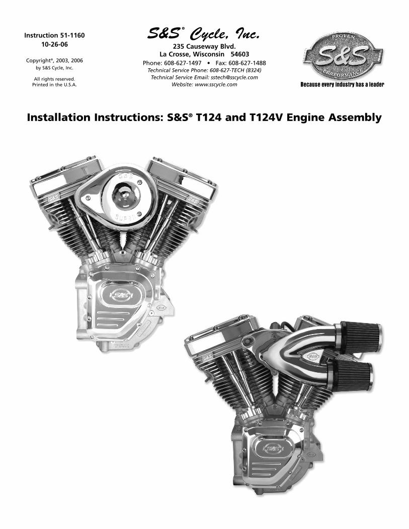
Installation Instructions: S&S® T124 and T124V Engine Assembly
S&S ® Cycle, Inc.235 Causeway Blvd.
La Crosse, Wisconsin 54603Phone: 608-627-1497 • Fax: 608-627-1488
Technical Service Phone: 608-627-TECH (8324)Technical Service Email: [email protected]
Website: www.sscycle.com

2
SAFE INSTALLATION AND OPERATION RULES:
Before installing your new S&S part it is your responsibility to read andfollow the installation and maintenance procedures in theseinstructions and follow the basic rules below for your personal safety.
l Gasoline is extremely flammable and explosive under certainconditions and toxic when inhaled. Do not smoke. Perform installationin a well ventilated area away from open flames or sparks.
l If motorcycle has been running, wait until engine and exhaust pipeshave cooled down to avoid getting burned before performing anyinstallation steps.
l Before performing any installation steps disconnect battery toeliminate potential sparks and inadvertent engagement of starter whileworking on electrical components.
l Read instructions thoroughly and carefully so all procedures arecompletely understood before performing any installation steps.Contact S&S with any questions you may have if any steps are unclearor any abnormalities occur during installation or operation ofmotorcycle with a S&S part on it.
l Consult an appropriate service manual for your motorcycle for correctdisassembly and reassembly procedures for any parts that need to beremoved to facilitate installation.
l Use good judgement when performing installation and operatingmotorcycle. Good judgement begins with a clear head. Don't letalcohol, drugs or fatigue impair your judgement. Start installationwhen you are fresh.
l Be sure all federal, state and local laws are obeyed with theinstallation.
l For optimum performance and safety and to minimize potentialdamage to carb or other components, use all mounting hardware thatis provided and follow all installation instructions.
l Motorcycle exhaust fumes are toxic and poisonous and must notbe inhaled. Run motorcycle in a well ventilated area where fumescan dissipate.
DISCLAIMER:
S&S parts are designed for high performance, off road, racingapplications and are intended for the very experienced rider only. Theinstallation of S&S parts may void or adversely effect your factorywarranty. In addition such installation and use may violate certainfederal, state, and local laws, rules and ordinances as well as other lawswhen used on motor vehicles used on public highways, especially instates where pollution laws may apply. Always check federal, state, andlocal laws before modifying your motorcycle. It is the sole and exclusiveresponsibility of the user to determine the suitability of the product forhis or her use, and the user shall assume all legal, personal injury risk andliability and all other obligations, duties, and risks associated therewith.
The words Harley®, Harley-Davidson®, H-D®, Sportster®, Evolution®, andall H-D part numbers and model designations are used in reference only.S&S Cycle is not associated with Harley-Davidson, Inc.
IMPORTANT NOTICE:Statements in this instruction sheet preceded by the following wordsare of special significance.
WARNINGMeans there is the possibility of injury to yourself or others.
CAUTIONMeans there is the possibility of damage to the part or motorcycle.
NOTEOther information of particular importance has been placed in italic type.
S&S recommends you take special notice of these items.
WARRANTY:All S&S parts are guaranteed to the original purchaser to be free ofmanufacturing defects in materials and workmanship for a period oftwelve (12) months from the date of purchase. Merchandise that failsto conform to these conditions will be repaired or replaced at S&S’soption if the parts are returned to us by the purchaser within the 12month warranty period or within 10 days thereafter.
In the event warranty service is required, the original purchaser mustcall or write S&S immediately with the problem. Some problems can berectified by a telephone call and need no further course of action.
A part that is suspect of being defective must not be replaced by aDealer without prior authorization from S&S. If it is deemed necessaryfor S&S to make an evaluation to determine whether the part wasdefective, a return authorization number must be obtained from S&S.The parts must be packaged properly so as to not cause further damageand be returned prepaid to S&S with a copy of the original invoice ofpurchase and a detailed letter outlining the nature of the problem, howthe part was used and the circumstances at the time of failure. If afteran evaluation has been made by S&S and the part was found to bedefective, repair, replacement or refund will be granted.
ADDITIONAL WARRANTY PROVISIONS:(1) S&S shall have no obligation in the event an S&S part is modified byany other person or organization.
(2) S&S shall have no obligation if an S&S part becomes defective inwhole or in part as a result of improper installation, impropermaintenance, improper use, abnormal operation, or any other misuseor mistreatment of the S&S part.
(3) S&S shall not be liable for any consequential or incidental damagesresulting from the failure of an S&S part, the breach of any warranties,the failure to deliver, delay in delivery, delivery in non-conformingcondition, or for any other breach of contract or duty between S&S anda customer.
(4) S&S parts are designed exclusively for use in Harley-Davidson® andother American v-twin motorcycles. S&S shall have no warranty orliability obligation if an S&S part is used in any other application.
1- IntroductionS&S® T124 Engines are available in two versions The firstversion is designed and intended for installation in a stockHarley-Davidson® Twin Cam 88® chassis. It will bolt directlyto the stock transmission and engine mounts of chassisdesigned for stock Twin Cam 88® engines. The secondversion the T124V is machined with an 1984-1999 rearmotor mount. It may be installed in a stock or Harley-Davidson® Evolution® chassis. Both versions are availablein natural aluminum or black powder coat finish.
The oil lines for the T124V engine connect to the engineon the rear of the cam chest. The top fitting is oil return.The lower fitting is oil supply.
Installation can be performed by any Harley-Davidson®
repair shop equipped to do complete engine overhauls.
No special tools other than those used in normal enginebuilding operations are required.
NOTESl Installation of a fuel injected engine in a motorcycle that
was originally equipped with a carburetor is fairly difficultand expensive. This conversion requires a fuel pumpequipped gas tank as well as wiring harness.
l All S&S T124 assemblies are for Twin Cam 88® non-counterbalanced engine applications, and are not for usein Twin Cam 88B® counterbalanced applications.
3
7- Oil Line Installation8- Exhaust System9- Initial Start-up and Engine Break-In10- Tuning Guidelines11- Engine Specs and Torque Values12- Service Intervals
Instruction Contents:1- Introduction2- Additional Features3- Modification Notes4- Engine to Frame Assembly5- Ignition System6- Fuel System
Please read these instructions carefully before starting work. Proceed with the installation only after the instructions arecompletely understood. These instructions should be supplemented by the appropriate OEM service manual for yourmotorcycle. Follow all safety information.
2- Additional Features:l Greater overall strength than stock crankcases, especially
in the front motor mount, an important consideration inhigh performance applications.
l All oil passages between the crankcase and cam supportplate are O-ring sealed.
l Compatible with stock components. Use stock oil pump,cam support plate, gear cover, etc.
l Uses 1999-2002 Timken® style sprocket shaft bearing. l Uses 2003-up pinion shaft bearing
S&S® T124 and T124V instructions often refer toprocedures described in other S&S instructions or aHarley-Davidson® Service Manual. These materials shouldbe cross-referenced as necessary.
IMPORTANTBefore proceeding, verify that serial numbers on crankcasesmatch numbers on packing carton and certificate of origin.Contact S&S immediately if numbers do not match.
NOTE - Valid certificate of origin is required for any transferor sale of longblock assemblies. Certificate of origin isrequired to title and license any motorcycle which is to bedriven on public streets and highways.
4
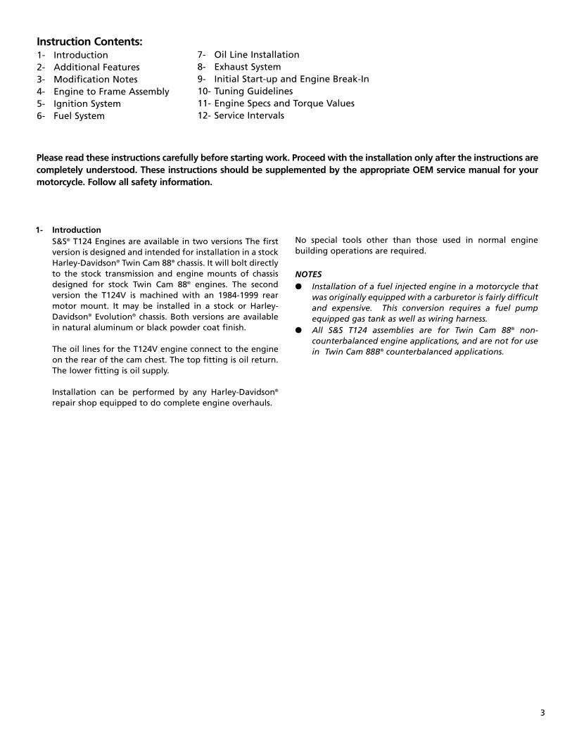
Dynomometer chart showing typical horsepower and torque curves for S&S 124” T124 engine.
Horsepower and torque curves will vary, dependent on the engines state of tune, and the ignition and fuel systemsused on the completed engine.
Torque
Horsepower
5
3- Modification NotesS&S® Cycle cautions against modifying these crankcasesdue to the possibility of damaging or weakening them.Modifying S&S crankcases in any fashion voids allmanufacturer warranties. Should the customer elect tomodify the crankcases regardless, it is imperative thatthey and the information tag attached to them beinspected beforehand to confirm that the correct model,style, bore size, etc. have been provided. The customermust confirm that crankcases and related parts are correctbefore assembling them or having them modified in anymanner, and assumes all liability for modifications.
Under no circumstance will S&S be held responsible forexpenses related to the modification of any S&S part inthe event warranty service is required. Modified parts willnot be accepted for credit or exchange. This will applyregardless of cause or fault: customer, retailer,manufacturer, or other.
For further information, contact S&S Technical Services at608-627-8324, FAX 608-627-1488 or [email protected]
NOTE - Modification includes but is not limited to appearancechanges such as painting, powdercoating, plating, andpolishing. Proper preparation for these procedures as well asthe processes themselves may require the use of polishingcompounds, chemicals or procedures that are potentiallyharmful to crankcases.
l Passages and internal cavities may become obstructed byresidues from materials used to polish, paint, plate orpowdercoat surfaces. Additionally, surface finishingprocesses can damage critical machined surfaces. Any ofthe above may cause premature wear, damage or failureof other engine components as well as the crankcasesthemselves.
l Glass bead and polishing residues are abrasive and can bedifficult to remove from recesses and small passages.Abrasive residues can cause oil contamination andextensive engine damage. Engine damage caused bypowder coating, polishing, glass bead blasting, or othermodification will not be covered under warranty.
Powder Coating - Subjecting heat-treated alloys such asthose used in S&S crankcases to excessive heat candrastically alter their strength and their critical properties.The degree of change depends upon the temperaturesreached and the duration of exposure. When powdercoating or otherwise processing alloy parts, S&S exposesthem to a maximum temperature of 370°F for no longerthan 20 minutes. Under no circumstances should parts beheated past 400°F!
S&S strongly recommends trial-fitting every enginebefore frame is painted or powdercoated.
4- Engine To Frame AssemblyThe engine should be installed into the frame beforethe ignition, fuel, exhaust, and oil system componentsare installed.
Follow the engine to frame fitting below:
Engine to Frame Test Fit
NOTE - The engine must be fitted to the frame it is installedinto. It must rest squarely on its attachment points, and boltedsolidly to the frame without stressing the engine case at anypoint.
Failure to correctly mount the engine can cause problems notcovered under warranty including but not limited to,excessive vibration, driveline mis-alignment, and brokencastings.
A- Test-fit instructions for T124 style cases with stock1999-up engine mounts.
1- Clean frame engine mounts and carefully removeany irregularities from mounting surfaces. Alsoinspect crankcase mounting bosses for burrs.
2- Position engine in frame, check for clearance atframe, and alignment to transmission. It is agood idea to replace rubber engine mounts atthis time. Old mounts deform over time and caninduce unwanted stresses on the engine case.
Improper alignment of engine and frame mounts may causeabnormal stresses resulting in damage to crankcases or otherparts.
B- Test-fit instructions for T124V style cases with 1984-1999 mounts.
1- Clean frame engine mounts and carefully removeany irregularities from mounting surfaces. Alsoinspect crankcase mounting bosses for burrs.
2- Position engine assembly in frame.
3- Install engine mounting bolts in motor mounts, andcheck clearance between mounting bosses on casesand frame and any other areas where frame andcases may contact each other. Bolts may be difficultto install if contact is severe.
4- If engine contact frame, remove it and relievejust enough material in offending area toprovide clearance.
5- Place engine in frame, install one rear mountingbolt and snug nut.
6- Measure gap between crankcase mountingbosses and frame motor mounts with feelergauge to determine if shimming is required.
CAUTION
CAUTION
CAUTION
6
7- If gap exists, fabricate shim just thick enough tofill gap
8- Install opposite corner shim and mounting boltand nut, and tighten identical to other bolt.
9- Check other corners with feeler gauge to confirmthickness required is same as before. If not,determine cause and correct.
NOTE- S&S® T124V engine installation in 1984-1999 designmotorcycle frame is essentially the same as stock, althoughadditional clearancing and shimming may occasionally berequired. When this style of case is solid mounted instead ofrubber mounted, additional care must be taken in installingthe case. Main areas of concern are between cases and framemotor mounts. Checking clearance around and between casemounting bosses and frame is necessary to insure thatcrankcase rests squarely on motor mount pad and no stress isapplied to crankcases when mounting bolts are tightened.Shimming may be required to compensate for variancesbetween frames.
Replace all other motorcycle components removed forengine installation. Consult authorized Harley-Davidson®
service manual for installation procedure for stock partsnot covered in S&S instructions.
NOTE- On certain models it may be necessary to switch theshift linkage to the outside of the shift lever. Make certainthat there is clearance between the shifter rod and the enginecrankcases.
5- Ignition System Installation
A- All Carbureted S&S T124 and T124V assemblies comewith an S&S IST (Intelligent Spark Technology)ignition. Use of this ignition system is highlyrecommended. All aspects of ignition timing-advance, retard, and curves are handledautomatically by the S&S IST ignition.
B- Once the IST ignition has been installed per theincluded instruction sheet 51-1155, no otheradjustments are necessary
NOTESl If the S&S IST ignition is not used, S&S recommends using
electronic ignition with adjustable advance curve in S&ST124 and T124V engines. Adjustable curve permitsslowing rate of advance to control or eliminate pingingunder heavy load or when elevated temperatures or poorquality gasoline encountered.
l All other ignition systems other than the included S&S ISTignition install per manufacturers instructions.S&Srecommends setting the total ignition advance to 28degrees. Timing degree recommendations given by S&Stake precedence over the ignition manufacturersinstructions.
Timing that is too advanced will result in detonation andengine damage. Timing that is too retarded will result inengine over-heating and engine damage. (This cautionapplies only to installations other than the S&S IST Ignition)
If S&S determines that engine damage was caused byimproper ignition timing, repair will not be covered underwarranty.
Excessive ignition advance will cause engine to kick backagainst the starter during start-up and “buck” when ridden atsteady speed with partial throttle. An advanced condition canalso cause pinging or ignition knock and possible pistondamage. These symptoms may not be noticed if electronicignition with “soft” advance curve is used.
Excessive ignition retard causes sluggish performance andsevere overheating with possible subsequent damage to theengine, and must also be avoided. Immediate or rapid exhaustpipe discoloration is usually a sign of retarded ignition timing.
6- Fuel system installation and tuning
NOTES - S&S® Engine assemblies are available with eithercarbureted or fuel injected systems.
Assembled Engines are shipped with the carburetor or fuelinjection system installed. Refer to the included instructions foroperation and tuning .
A- Install fuel system.
1- Engine assemblies supplied with Super “G”carburetors, refer to included instruction sheet51-1012.
2- Engine assemblies supplied with Super “D”carburetors,refer to included Special ApplicationRacing Carburetor Supplement for additionalinformation.
3- Engine assemblies supplied with fuel injection, referto included Induction System instruction Sheet.
B- Re-install and connect fuel tank.
1- Refer to appropriate service manual. Inspect fuellines and clamps - replace as necessary.
2- Check fuel line connections and routing. Avoidhot surfaces. Make certain that the protectivecover has been placed over fuel line, and that itis clear from sharp edges and abrasive surfaces.
3- Fill the fuel tank with a sufficient quantity ofgasoline for the initial start-up procedure.
4- Double check that all fuel line connections havebeen made correctly and there is no gas leakageat any point in the system.
CAUTION
CAUTION
7- Oil Line Installation
A- For 1999-2006 Harley-Davidson® FL models
Oil line installation is crucial to engine life. If you are not surethat you can properly perform this operation, please contactthe S&S Tech Department for a referral to a shop in your area.
NOTE- Installation instructions are based on an engine andtransmission already in the chassis.
NOTE- Apply thread sealant to all tapered pipe threads.
1- Remove the stock oil supply and return fittingsfrom the transmission.
2- Install two supplied 3⁄8 NPT pipe plugs (S&S PN 50-8330)in the oil fitting location.
NOTE- Apply thread sealant to all tapered pipe threads.
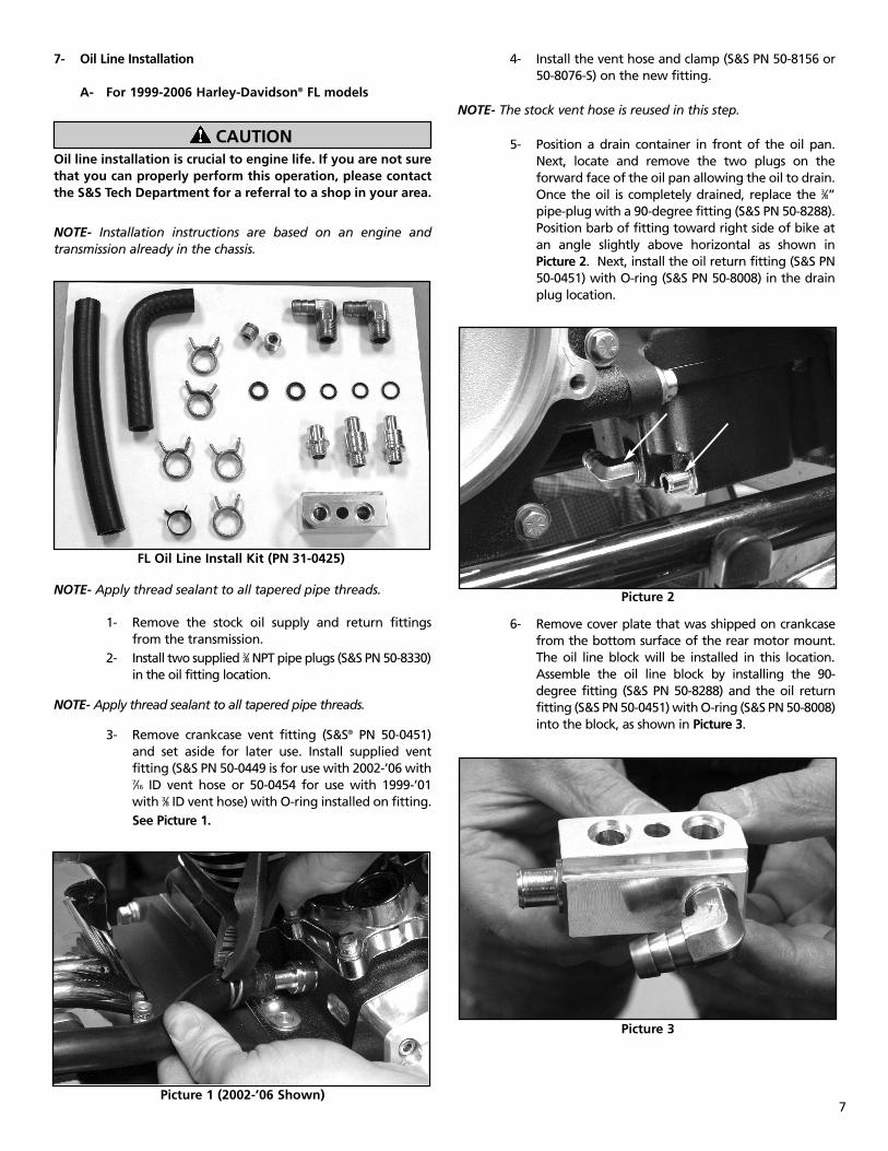
3- Remove crankcase vent fitting (S&S® PN 50-0451)and set aside for later use. Install supplied ventfitting (S&S PN 50-0449 is for use with 2002-’06 with7⁄16 ID vent hose or 50-0454 for use with 1999-’01with 3⁄8 ID vent hose) with O-ring installed on fitting.See Picture 1.
4- Install the vent hose and clamp (S&S PN 50-8156 or50-8076-S) on the new fitting.
NOTE- The stock vent hose is reused in this step.
5- Position a drain container in front of the oil pan.Next, locate and remove the two plugs on theforward face of the oil pan allowing the oil to drain.Once the oil is completely drained, replace the 3⁄8”pipe-plug with a 90-degree fitting (S&S PN 50-8288).Position barb of fitting toward right side of bike atan angle slightly above horizontal as shown inPicture 2. Next, install the oil return fitting (S&S PN50-0451) with O-ring (S&S PN 50-8008) in the drainplug location.
6- Remove cover plate that was shipped on crankcasefrom the bottom surface of the rear motor mount.The oil line block will be installed in this location.Assemble the oil line block by installing the 90-degree fitting (S&S PN 50-8288) and the oil returnfitting (S&S PN 50-0451) with O-ring (S&S PN 50-8008)into the block, as shown in Picture 3.
7
CAUTION
FL Oil Line Install Kit (PN 31-0425)
Picture 1 (2002-’06 Shown)
Picture 2
Picture 3
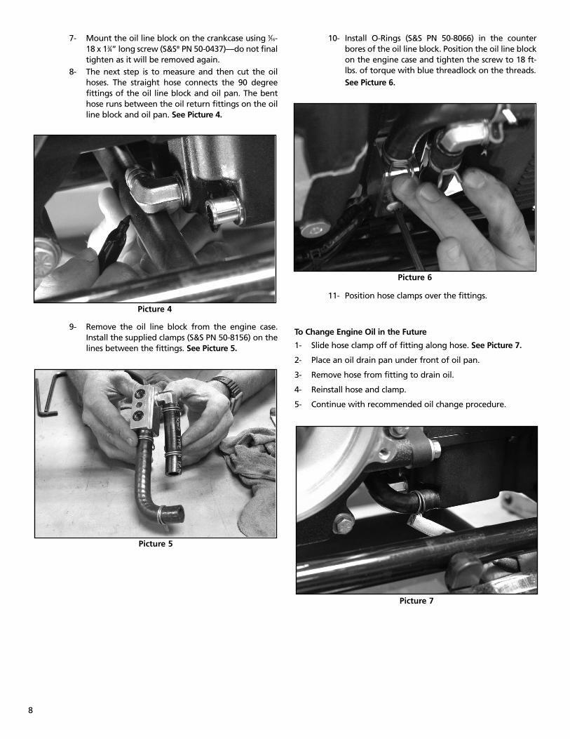
7- Mount the oil line block on the crankcase using 5⁄16-18 x 13⁄4” long screw (S&S® PN 50-0437)—do not finaltighten as it will be removed again.
8- The next step is to measure and then cut the oilhoses. The straight hose connects the 90 degreefittings of the oil line block and oil pan. The benthose runs between the oil return fittings on the oilline block and oil pan. See Picture 4.
9- Remove the oil line block from the engine case.Install the supplied clamps (S&S PN 50-8156) on thelines between the fittings. See Picture 5.
10- Install O-Rings (S&S PN 50-8066) in the counterbores of the oil line block. Position the oil line blockon the engine case and tighten the screw to 18 ft-lbs. of torque with blue threadlock on the threads.See Picture 6.
11- Position hose clamps over the fittings.
To Change Engine Oil in the Future
1- Slide hose clamp off of fitting along hose. See Picture 7.
2- Place an oil drain pan under front of oil pan.
3- Remove hose from fitting to drain oil.
4- Reinstall hose and clamp.
5- Continue with recommended oil change procedure.
8
Picture 4
Picture 5
Picture 6
Picture 7
9
1- Block, Oil line .........................................................106-11682- BHSHCS, 5⁄16-18 x 13⁄4 (10 pack) .................................106-11693- O-ring (10 pack).........................................................50-80664- Fitting, Pipe, 90 degree (2 pack)...........................106-11705- Fitting,
7⁄16 (2 pack) ............................................................106-11713⁄8 (2 pack) ............................................................106-1172
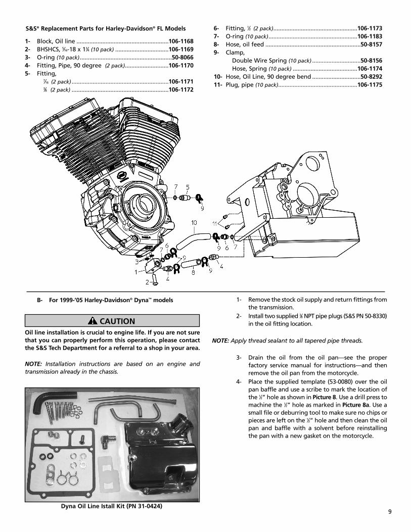
S&S® Replacement Parts for Harley-Davidson® FL Models 6- Fitting, 1⁄2 (2 pack)....................................................106-11737- O-ring (10 pack).......................................................106-11838- Hose, oil feed ...........................................................50-81579- Clamp,
Double Wire Spring (10 pack) ..............................50-8156Hose, Spring (10 pack) ........................................106-1174
10- Hose, Oil Line, 90 degree bend ..............................50-829211- Plug, pipe (10 pack).................................................106-1175
B- For 1999-’05 Harley-Davidson® Dyna™ models
Oil line installation is crucial to engine life. If you are not surethat you can properly perform this operation, please contactthe S&S Tech Department for a referral to a shop in your area.
NOTE: Installation instructions are based on an engine andtransmission already in the chassis.
1- Remove the stock oil supply and return fittings fromthe transmission.
2- Install two supplied 3⁄8 NPT pipe plugs (S&S PN 50-8330)in the oil fitting location.
NOTE: Apply thread sealant to all tapered pipe threads.
3- Drain the oil from the oil pan—see the properfactory service manual for instructions—and thenremove the oil pan from the motorcycle.
4- Place the supplied template (53-0080) over the oilpan baffle and use a scribe to mark the location ofthe 1⁄2” hole as shown in Picture 8. Use a drill press tomachine the 1⁄2” hole as marked in Picture 8a. Use asmall file or deburring tool to make sure no chips orpieces are left on the 1⁄2” hole and then clean the oilpan and baffle with a solvent before reinstallingthe pan with a new gasket on the motorcycle.
CAUTION
Dyna Oil Line Istall Kit (PN 31-0424)
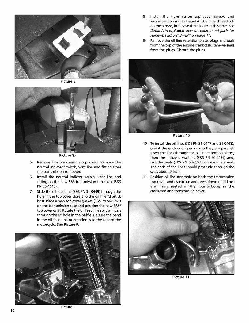
5- Remove the transmission top cover. Remove theneutral indicator switch, vent line and fitting fromthe transmission top cover.
6- Install the neutral indictor switch, vent line andfitting on the new S&S transmission top cover (S&SPN 56-1615).
7- Slide the oil feed line (S&S PN 31-0449) through thehole in the top cover closest to the oil filler/dipstickboss. Place a new top cover gasket (S&S PN 56-1261)on the transmission case and position the new S&S®
top cover on it. Rotate the oil feed line so it will passthrough the 1⁄2” hole in the baffle. Be sure the bendin the oil feed line orientation is to the rear of themotorcycle. See Picture 9.
8- Install the transmission top cover screws andwashers according to Detail A. Use blue threadlockon the screws, but leave them loose at this time. SeeDetail A in exploded view of replacement parts forHarley-Davidson® DynaTM on page 11.
9- Remove the oil line retention plate, plugs and sealsfrom the top of the engine crankcase. Remove sealsfrom the plugs. Discard the plugs.
10- To install the oil lines (S&S PN 31-0447 and 31-0448),orient the ends and openings so they are parallel.Insert the lines through the oil line retention plates,then the included washers (S&S PN 50-0439) and,last the seals (S&S PN 50-8271) on each line end.The ends of the lines should protrude through theseals about 1⁄8 inch.
11- Position oil line assembly on both the transmissiontop cover and crankcase and press down until linesare firmly seated in the counterbores in thecrankcase and transmission cover.
10Picture 9
Picture 8a
Picture 10
Picture 11
Picture 8
12- Press the oil line retention plates into place untilthey seat. Install the two screws (5⁄16-18 x 3⁄4 buttonhead) through the oil line retention plates. Firstscrew goes in the transmission top cover and thesecond mounts into the crankcase near the rearmotor mount. Treat both screws with bluethreadlock and tighten to 18-ft-lbs.
13- Tighten transmission top cover screws to 100-120 in-lbs.14- Install the vent line (S&S PN 50-8291) with clamps
(S&S PN 50-8156).15- Reconect neutral switch wires.16- Check function of neutral switch.
11
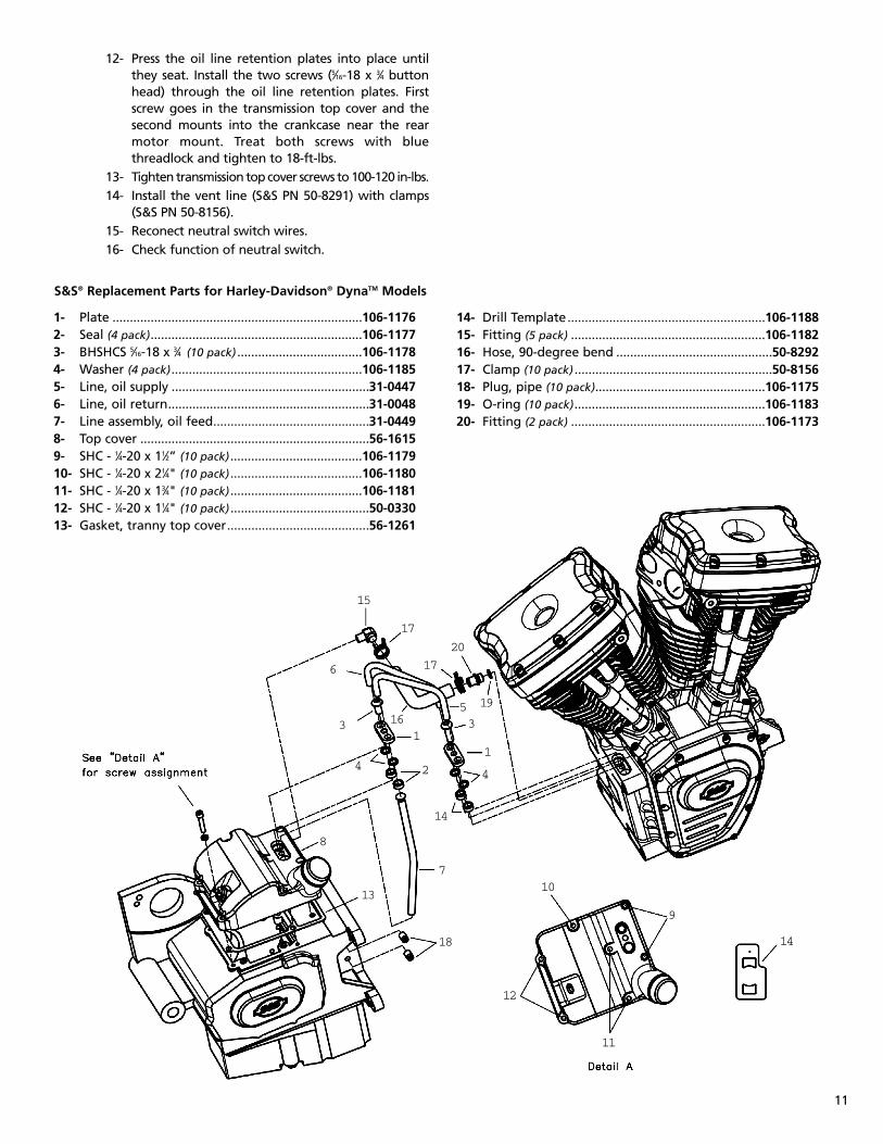
S&S® Replacement Parts for Harley-Davidson® DynaTM Models
1- Plate ........................................................................106-11762- Seal (4 pack).............................................................106-11773- BHSHCS 5⁄16-18 x 3⁄4 (10 pack) ....................................106-11784- Washer (4 pack).......................................................106-11855- Line, oil supply .........................................................31-04476- Line, oil return..........................................................31-00487- Line assembly, oil feed.............................................31-04498- Top cover ..................................................................56-16159- SHC - 1⁄4-20 x 11⁄2” (10 pack)......................................106-117910- SHC - 1⁄4-20 x 21⁄4" (10 pack)......................................106-118011- SHC - 1⁄4-20 x 13⁄4" (10 pack)......................................106-118112- SHC - 1⁄4-20 x 11⁄4" (10 pack) ........................................50-033013- Gasket, tranny top cover.........................................56-1261
14- Drill Template.........................................................106-118815- Fitting (5 pack) ........................................................106-118216- Hose, 90-degree bend .............................................50-829217- Clamp (10 pack) .........................................................50-815618- Plug, pipe (10 pack).................................................106-117519- O-ring (10 pack).......................................................106-118320- Fitting (2 pack) ........................................................106-1173
11
14
1
12
9
18
7
14
13
8
3
4 2 4
1
35 19
20
16
6
17
15
17
10

12
C- Oil recommendations
NOTESl S&S® Cycle recommends the use of Mobil 1® V-TWIN 20W-
50 synthetic oil in our engines.l S&S Cycle recommends the use of S&S® oil filters, PN 31-4103
(black), or PN 31-4104 (chrome).
All reference to Harley-Davidson® part numbers is foridentification purposes only. We in no way are implying thatany of S&S® Cycle’s products are original equipment parts orthat they are equivalent to the corresponding Harley-Davidson® part number shown.
If not using Mobil 1® V-TWIN 20W-50:
D- Verify oiling system operation before starting
If engine is run with foreign material in the oil tank, enginedamage will occur. Engine damage caused by foreign materialin the oil tank is not covered under the S&S warranty.
Restricted oil flow may result in extensive engine damage notcovered under warranty.
Improper installation of oil lines or fittings may result in partsdamage not covered under warranty.
1- Fill the oil tank to the proper level.
2 - Remove spark plugs. Ground plug wires tocylinder head with either a jumper wire orthrough a test plug.
3- Remove oil sender unit.
4- Turn ignition on and turn the engine over withthe starter motor until engine oil appears at theoil pressure sender hole.
5- Re-install and re-connect oil sender unit.
6- Verify that engine oil is returning to oil tank.
7- Start motorcycle. Verify oil pressure by watchingoil pressure light.
NOTESl If oil fails to appear at oil sender hole within 30 seconds
of starter operation, allow the starter to cool. Verify thatoil line routing is correct and that the oil tank is full to theproper level.
l Oil pressure indicator lamp should light when ignition isturned on. Lamp will go out after engine is started andthere is oil pressure at the switch in the crankcase.
Avoid excessive time of starter engagement. Overheating ofstarter motor will result in damage. Oil pump should primeand deliver oil to the oil sender hole within 30 seconds.
8- Exhaust System
NOTE - The engine must be correctly mounted into the framebefore the exhaust system is installed.
1- Place new woven-metal gasket into exhaust ports ofcylinder heads.
2- Inspect the exhaust pipe header flanges and retainingrings. Replace if distorted, warped, or otherwisedamaged.
3- Apply a high-temp. anti-seize lubricant to threads ofexhaust studs at cylinder heads.
4- Install exhausts to cylinder heads. Hand tightenexhaust stud nuts.
5- Attach exhausts to lower mounting bracket. Shim ifnecessary. Hand tighten mounting hardware.
6- Tighten exhaust flange nuts at head to 60-80 in-lbs.
In some instances, brake master cylinder must be spaced outfrom frame to clear crankcase. UNDER NO CIRCUMSTANCESSHOULD MASTER CYLINDER OR BRAKE LINE BE ALLOWED TOCONTACT EXHAUST PIPE IN FINAL INSTALLATION. Heattransferred to brake fluid may expand and cause brakes toseize, resulting in possible fire hazard and loss of control ofmotorcycle with injury or death to rider and others.
NOTE - Make certain that the exhaust system is not pre-loaded, or in a bind, at the lower mounting points. Make allspacing adjustments prior to final-tightening of the upperexhaust mounting hardware at the cylinder heads. Failure tofollow this procedure may cause excessive vibration and resultin failure of exhaust pipes or mounting hardware.
Viscosity Ambient Temperature (º F)
SAE 20W50 Above 20º - 100º
SAE 50 Above 60º - 100º
SAE 60 Above 80º - 100º
CAUTION
CAUTION
CAUTION
WARNING
CAUTION
9- Initial Start-Up And Engine Break-In
NOTE - engines are designed for high performance and assuch are not as tolerant of inadequate break-in as stock orlower performance engines. Correct break-in will assurelonger engine life and will prevent unnecessary enginedamage. Engine damage caused by improper break-in is notcovered under the S&S® warranty.
A- Initial start-up
1- For the initial start up, the fuel and ignitionsystems should be adjusted to their baselinesettings. (Baseline settings allow the bike to startand run, and are the starting point for tuning.)This is adequate for the initial start-up and heat-cycling of the engine.
NOTE - Because there are several ignition and fuel systemcombinations possible with the S&S® T124 and T124V engine,baseline settings are not listed here. Refer to the appropriateignition or fuel system instruction sheet.
2- Run engine approximately one minute at 1250-1750 rpm. DO NOT crack throttle or subject toany loads during this period as head gaskets aresusceptible to failure at this time. During thistime, check to see that oil pressure is normal, andthat oil is returning the oil tank.
3- Shut off engine and thoroughly check for any oilleaks, fuel leaks, or other problems. Let enginecool to the touch.
4- After engine has cooled, start up again and allowthe motor to build some heat. Engine should notbe run longer than three to four minutes. Whenthe cylinders become warm/hot to the touch(approximately 150°) shut the motor down and letit cool to room temp. Follow the same cautions asfor the initial start-up, and continue to watch forproblems.
5- Repeat this procedure 3 or 4 times. Eachsuccessive time it should take slightly longer towarm up and you can increase the temperatureslightly each time. You can be more liberal eachtime with the rpm, gently vary rpm continuouslyfrom idle up to 2500 rpm in the final cycle. Themotor should not reach full operatingtemperature during these cycles. Do not allowengine temperature to become excessive.
B. Engine break-in
1- Closely monitor engine for excessive heat build-up. Do not allow the engine to idle for longperiods of time. Be especially watchful when airtemperatures exceed 90 degrees. Slow speedoperation in urban areas during the summertimeis especially hard on engines.. Temperature forengine oil should be between 180º - 240º F. Ifengine oil temperature stays above 220º F, andcorrect ignition timing has been verified, S&S®
Cycle suggests that an oil cooler be installed. Donot run engine under conditions where oiltemperatures continue to remain high.
2- For the first 50 miles ride the motorcycle in a veryconservative manner. The first 50 miles are mostcritical for new rings and piston break-in. Enginedamage is most likely to occur during this period.Keep heat down by not exceeding 2500 rpm.Avoid lugging the motor, riding in hot weatheror in traffic. Vary the engine speed. Do not lugthe engine. Change the oil at 50 miles. This willremove the heavy accumulation of break inresidue from the oiling system.
3- The next 500 miles should be spent runningengine no faster than 3500 rpm or 60 mph.Correct any obvious ignition or fuel problems, ifpresent. Avoid continuous steady speeds, and donot lug the engine. Vary engine rpm. change theoil again at 500 miles.
Lugging or running engine prematurely at sustained high rpmmay result in damage to pistons and other enginecomponents. S&S voids it’s guarantee if engine is not brokenin properly.
4- For the balance of the first 1000 miles the motorcan be run in a normal but conservative manner.You can be more liberal with the rpm range andmotorcycle can be operated at normal highwayspeeds. Avoid overheating or putting any hardstrain on the engine: no drag racing, dyno runs,excessive speed, trailer towing or sidecaroperation.
5- After 1000 miles, verify Ignition and fuel systemsettings and adjustments. Change the engine oil.The break in process is complete.
13
CAUTION
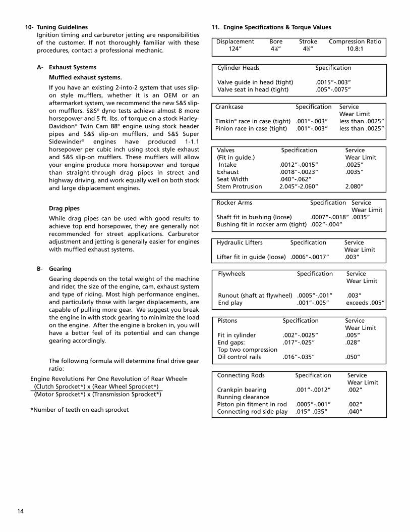
10- Tuning GuidelinesIgnition timing and carburetor jetting are responsibilitiesof the customer. If not thoroughly familiar with theseprocedures, contact a professional mechanic.
A- Exhaust Systems
Muffled exhaust systems.
If you have an existing 2-into-2 system that uses slip-on style mufflers, whether it is an OEM or anaftermarket system, we recommend the new S&S slip-on mufflers. S&S® dyno tests achieve almost 8 morehorsepower and 5 ft. lbs. of torque on a stock Harley-Davidson® Twin Cam 88® engine using stock headerpipes and S&S slip-on mufflers, and S&S SuperSidewinder® engines have produced 1-1.1horsepower per cubic inch using stock style exhaustand S&S slip-on mufflers. These mufflers will allowyour engine produce more horsepower and torquethan straight-through drag pipes in street andhighway driving, and work equally well on both stockand large displacement engines.
Drag pipes
While drag pipes can be used with good results toachieve top end horsepower, they are generally notrecommended for street applications. Carburetoradjustment and jetting is generally easier for engineswith muffled exhaust systems.
B- Gearing
Gearing depends on the total weight of the machineand rider, the size of the engine, cam, exhaust systemand type of riding. Most high performance engines,and particularly those with larger displacements, arecapable of pulling more gear. We suggest you breakthe engine in with stock gearing to minimize the loadon the engine. After the engine is broken in, you willhave a better feel of its potential and can changegearing accordingly.
The following formula will determine final drive gearratio:
Engine Revolutions Per One Revolution of Rear Wheel=(Clutch Sprocket*) x (Rear Wheel Sprocket*)(Motor Sprocket*) x (Transmission Sprocket*)
*Number of teeth on each sprocket
11. Engine Specifications & Torque Values
14
Displacement Bore Stroke Compression Ratio124” 41⁄8” 45⁄8” 10.8:1
Cylinder Heads Specification
Valve guide in head (tight) .0015”-.003”Valve seat in head (tight) .005”-.0075”
Valves Specification Service(Fit in guide.) Wear LimitIntake .0012”-.0015” .0025”
Exhaust .0018”-.0023” .0035”Seat Width .040”-.062”Stem Protrusion 2.045”-2.060” 2.080”
Rocker Arms Specification ServiceWear Limit
Shaft fit in bushing (loose) .0007”-.0018” .0035”Bushing fit in rocker arm (tight) .002”-.004”
Hydraulic Lifters Specification ServiceWear Limit
Lifter fit in guide (loose) .0006”-.0017” .003”
Pistons Specification ServiceWear Limit
Fit in cylinder .002”-.0025” .005”End gaps: .017”-.025” .028”Top two compressionOil control rails .016”-.035” .050”
Crankcase Specification ServiceWear Limit
Timkin® race in case (tight) .001”-.003” less than .0025”Pinion race in case (tight) .001”-.003” less than .0025”
Connecting Rods Specification ServiceWear Limit
Crankpin bearing .001”-.0012” .002”Running clearancePiston pin fitment in rod .0005”-.001” .002”Connecting rod side-play .015”-.035” .040”
Flywheels Specification ServiceWear Limit
Runout (shaft at flywheel) .0005”-.001” .003”End play .001”-.005” exceeds .005”
15
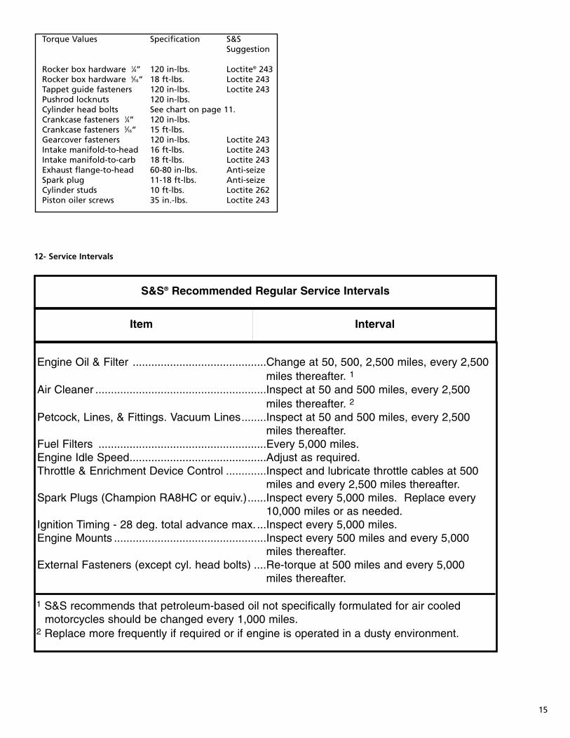
Torque Values Specification S&SSuggestion
Rocker box hardware 1⁄4” 120 in-lbs. Loctite® 243Rocker box hardware 5⁄16” 18 ft-lbs. Loctite 243Tappet guide fasteners 120 in-lbs. Loctite 243Pushrod locknuts 120 in-lbs.Cylinder head bolts See chart on page 11.Crankcase fasteners 1⁄4” 120 in-lbs.Crankcase fasteners 5⁄16” 15 ft-lbs.Gearcover fasteners 120 in-lbs. Loctite 243Intake manifold-to-head 16 ft-lbs. Loctite 243Intake manifold-to-carb 18 ft-lbs. Loctite 243Exhaust flange-to-head 60-80 in-lbs. Anti-seizeSpark plug 11-18 ft-lbs. Anti-seizeCylinder studs 10 ft-lbs. Loctite 262Piston oiler screws 35 in.-lbs. Loctite 243
S&S® Recommended Regular Service Intervals
Item Interval
Engine Oil & Filter ...........................................Change at 50, 500, 2,500 miles, every 2,500 ........................................................................miles thereafter. 1
Air Cleaner .......................................................Inspect at 50 and 500 miles, every 2,500 ........................................................................miles thereafter. 2
Petcock, Lines, & Fittings. Vacuum Lines........Inspect at 50 and 500 miles, every 2,500 ........................................................................miles thereafter.
Fuel Filters ......................................................Every 5,000 miles.Engine Idle Speed............................................Adjust as required.Throttle & Enrichment Device Control .............Inspect and lubricate throttle cables at 500 ........................................................................miles and every 2,500 miles thereafter.
Spark Plugs (Champion RA8HC or equiv.)......Inspect every 5,000 miles. Replace every ........................................................................10,000 miles or as needed.
Ignition Timing - 28 deg. total advance max. ...Inspect every 5,000 miles.Engine Mounts .................................................Inspect every 500 miles and every 5,000 ........................................................................miles thereafter.
External Fasteners (except cyl. head bolts) ....Re-torque at 500 miles and every 5,000 ........................................................................miles thereafter.
1 S&S recommends that petroleum-based oil not specifically formulated for air cooled motorcycles should be changed every 1,000 miles.
2 Replace more frequently if required or if engine is operated in a dusty environment.
12- Service Intervals
16
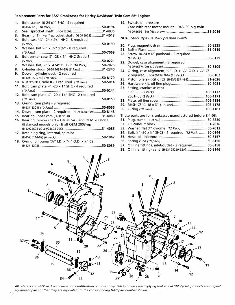
1. Bolt, stator 10-24 x1” SHC - 4 required(H-D#2720) (10 Pack) ....................................................50-0194
2. Seal, sprocket shaft (H-D#12068) ..............................31-40353. Bearing, Timken® sprocket shaft (H-D#9028)...........31-40134. Bolt, case 5⁄16” -24 x 23⁄4” HHC - 8 required
(5 Pack) .......................................................................50-01905. Washer, flat 5⁄16” x 11⁄16” x 1⁄16” - 8 required
(10 Pack) .....................................................................50-70696. Bolt center case 1⁄4” -28 x 6” HHC Grade 8
(5 Pack) .......................................................................50-02217. Washer, flat, 1⁄4” x .474” x .050” (10 Pack)................50-70768. Cylinder studs (H-D#16834-99) (8 Pack) ......................31-23409. Dowel, cylinder deck - 2 required
(H-D#16595-99) (10 Pack) ..............................................50-817910. Nut 1⁄4”-28 Grade 8 - 1 required (10 Pack) ...............50-501411. Bolt, cam plate 1⁄4” -20 x 1” SHC - 4 required
(10 Pack) .....................................................................50-024412. Bolt, cam plate 1⁄4” -20 x 11⁄4” SHC - 2 required
(10 Pack) .....................................................................50-015313. O-ring, cam plate - 9 required
(H-D#11301) (10 Pack) ..................................................50-806614. Dowel, cam plate - 2 required (H-D#16589-99) ........50-814815. Bearing, inner cam (H-D# 9198).................................31-408016. Bearing, pinion shaft – Fits all S&S and OEM 2000-’02
(Balanced models only) & all OEM 2003-up(H-D#24604-00 & #24604-00C) ........................................31-4085
17. Retaining ring, internal, spiraloc(H-D#35114-02) (6 pack)................................................50-1047
18. O-ring, oil pump 11⁄16” I.D. x 15⁄16” O.D. x 1⁄8” CS(H-D#11293) .................................................................50-8039
19. Switch, oil pressureCase with rear motor mount, 1948-’99 big twin(H-D#26561-84) (Not shown)..............................................31-2016
NOTE: Stock style use stock pressure switch.
20. Plug, magnetic drain ..............................................50-833521. Baffle Plate ..............................................................31-011922. Screw 10-24 x 3⁄8” panhead - 2 required
(10 Pack) .....................................................................50-013923. Dowel, case alignment - 2 required
(H-D#16574-99) (10 Pack) ..............................................50-810924. O-ring, case alignment, 9⁄16” I.D. x 11⁄16” O.D. x 1⁄16” CS
2 required, (H-D#26432-76A) (10 Pack) .......................50-810225. Piston oilers - (Kit of 2) (H-D#22371-99)....................31-202626. Hardware kit, oil line plugs.....................................50-108127. Fitting, crankcase vent
1999-'00 (2 Pack)......................................................106-11722001-'06 (2 Pack)......................................................106-1171
28. Plate, oil line cover ................................................106-118429. BHSH CS 5⁄16 -18 x 3⁄4" (10 Pack)..................................106-117830. O-ring (10 Pack) .......................................................106-1183
These parts are for crankcases manufactured before 8-1-06:31. Plug, sump (H-D#765).................................................50-833032. Oil conduit block......................................................31-207633. Washer, flat 1⁄4” chrome (12 Pack) ............................50-701334. Bolt, 1⁄4” -20 x 3⁄4” SHCS - 1 required (12 Pack) .........50-014435. Hose, oil, inlet/outlet ...............................................50-815736. Spring clips (10 pack).................................................50-815637. Oil line fittings, inlet/outlet - 2 required................50-815838. Oil line fitting- vent (H-D# 25259-93A)......................50-8146
Replacement Parts for S&S® Crankcases for Harley-Davidson® Twin Cam 88® Engines
All reference to H-D® part numbers is for identification purposes only. We in no way are implying that any of S&S Cycle’s products are originalequipment parts or that they are equivalent to the corresponding H-D® part number shown.
1
2
3
4
5
6
7
7
88
8
88
8
8
8
9
9
10
11
12
1314
12
14
15
15
1617
17
18
28 20
20
21
22
22
23
24
25
26
27 2930
31
32
13
13
3334
35
35
36
36
36
36
37
38
13
13


![Index [] · 2 Red Shift® Cams Twin Cam® Applications & Specs Red Shift® Application Matrix for 1999-Up Twin Cam ® Engines Red Shift® Specs for 1999-Up Twin Cam ® Engines 1999-2006](https://img.dokumen.tips/doc/110x75/5f94d203b8690b2d316b27c1/index-2-red-shift-cams-twin-cam-applications-specs-red-shift-application.jpg)