Embed Size (px)
Citation preview

Name(s):______________________________________Date box was packaged, inspected, weighed, & veri�ed to insure all parts were inside & correct:_____________
Packaging Inspection Check-O� Form
2014-18 GM 1500, 7”-9” LIFT KITPART# 50768, 50769, 50780, 50781
559-226-81964603 E. VINE AVE.
FRESNO, CA 93725www.mcgaughys.com
13. U-Bolts w/ Hardware (4)
6. Front Lift Spindles (2)
17. Lift Blocks
19. Lower A-Arm Support Rods (2)
14. Di�erential Drop Brackets (2)
20. Sway Bar Drop Brackets (2)
4 & 5. Compression Strut Brackets (4)
15. Hardware Pack
11. Sway Bar Extenders
10. Rear Bump Stop Extenders
22. Spare Tire Spacer
9. Weld-In Filler Plates (2)
16. CV Axle Spacers (2)
12. Outer Tie-Rod Ends (2)
8. Front Brake Line Bracket Extenders (2)
BOX 1 BOX 3
21. Rear Shocks (2)
2. Rear Crossmember
18. Compression Struts (2) w/ Bushings & Sleeves
3. Front Crossmember
1. Skid Plate
7. Adjustable Front Lift Struts (2)
BOX 2
Parts listed and pictured are for 4wd kits. If you ordered a 2wd kit, some
parts will be omitted.

559-226-81964603 E. VINE AVE.
FRESNO, CA 93725www.mcgaughys.com
- If you are the installer only, and not the owner of the vehicle, please makesure the owner of the vehicle gets these instructions. They contain very important information about the lift kit, maintainace, and warranty.
-Before moving forward with installation, please layout all parts from boxes and ensure everything is present. If any parts are missing, please contact McGaughy’s Suspension immediately at 559-226-8196.
-If you alter the �nish of any of the provided components, like zinc plating, chroming, or powder-coating, which can cause damage to the strength and structure of the metal, any warranties will be null and void.
-If any components are ground on or modi�ed in any way, then no returns or exchages will be accepted and any warranties will be null and void.
-NO welding is required to install any part of this lift kit. Do not weld any components.
-Over-sized tires and heavier wheels can cause premature wear on factory and aftermarket components like ball joints, bushings, tie-rod ends, wheelbearings, idler arms, drive-lines, etc.... You may need to replace / install newcomponents sooner than factory recommendations based on the tires and wheels you choose. Please note that the heavier and wider wheels and tirescombined with aggressive driving (o�-road and on highways) will cause morewear on ALL moving parts, factory and aftermarket. Especially when vehicle isin 4wd or Auto-4wd / AWD modes.
READ THESE ENTIRE INSTRUCTIONSBEFORE STARTING ANYTHING

-McGaughy’s warrants all McGaughy’s products against manufacturer’sdefects in materials or workmanship for a period of ONE-YEAR from the dateof original purchase. All McGaughy’s spindles carry a LIFETIME warrantyagainst manufacturer’s defects.
-Warranty will not extend to any product or part there in, that has beenimproperly installed, abused, or neglected
-McGaughy’s will not warranty any product(s) that were modi�ed in any way.Check �t all products prior to custom painting, powder-coating, or any formof fabrication (sanding, drilling, painting, chroming, etc).
-There are NO WARRANTIES neither espressed nor implied for powder-coating on any McGaughy’s products.
-McGaughy’s is not responsible for damages and/or warranty of other vehicle parts (factory or aftermarket) related or non-related to the install ofMcGaughy’s component(s).
-Warranty is limited to the repair or replacement (of McGaughy’s productonly), at McGaughy’s discretion. And only after inspection of the defectivepart, once returned to McGaughy’s with proof of purchase, date of purchase, and all shipping costs prepaid.
-Any cost of labor, freight, incidental or consequential damages are expresslyexcluded from warranty.
559-226-81964603 E. VINE AVE.
FRESNO, CA 93725www.mcgaughys.com
WARRANTY INFORMATION

559-226-81964603 E. VINE AVE.
FRESNO, CA 93725www.mcgaughys.com
2014-18 GM 1500, 7”-9” LIFT KITPART# 50768, 50769, 50780, 50781
***READ THESE ENTIRE INSTRUCTIONS BEFORE STARTING ANYTHING***-The factory wheels and tires will not �t on the front of vehicle once lift kit is installed, without using
the provided wheel spacer. One provided for use with spare tire only. You must use at least a 17”diameter wheel and 8” wide. With a maximum backspacing of 4-5/8”-This kit will not work on vehicles with factory auto ride suspension.
-If you have a 2wd vehicle, then you will disregard any instructions related to the front di�erentialand CV axles.
1.
9.10.
11.
2.
3.
4.12.
5.
13.
6.
14.
7.
15.
8.
16.
17. 18.
19.20.
21.22.
1. Skid Plate2. Rear Crossmember3. Front Crossmember4. Front Compression Strut Brackets5. Rear Compression Strut Brackets6. Front Lift Spindles7. Adjustable Front Lift Struts
8. Front Brake Line Brackets9. Weld-In Filler Plates10. Rear Bump Stop Extenders11. Sway Bar Extenders12. Outer Tie-Rod Ends13. U-Bolts14. Di�erential Drop Brackets15. Hardware Pack
16. CV Axle Spacers17. Rear Lift Blocks18. Compression Struts19. Lower A-Arm Support Rods20. Sway Bar Drop Brackets21. Rear Shocks22. Spare Tire Wheel Spacer

1.
FRONT INSTALLATION Always use the proper tools and consult the factory service manual for torque values and procedures. With the vehicle turned o� and the parking brake set, secure the rear wheels/tires with wheel chocks. Use a jack and lift the front of the vehicle. Place jack stands under the frame on both sides of the vehicle. Remove the front wheels.
1. Remove the factory outer tie-rod ends.2. Unplug the factory ABS line from the a-arm and the frame. Remove the factory brake hose bracket from the spindleand from the coil pocket.3. Disconnect the calipers and secure out of the way. Make sure they do not hang from the brake hose.4. Remove the factory clips on the wheel studs. Take o� the bearing cover, axle nut and washer, and the rotor with the hub bearing all as one unit. (pic 1)5. Unbolt the factory ball joints and remove the factory spindles.6. Remove the factory front struts from the vehicle.7. Remove the factory brake line bracket that connects the brake hose to the upper a-arm.8. Un-bolt and remove CV axles.9. Remove the sway bar end links from the lower a-arms. Un -bolt and remove sway bar from the vehicle completely.10. Now un-bolt and remove the factory lower a-arms. (pic 2)11. Remove the factory front skid plate and shield. (pic 3)12. Uninstall the driveshaft from the di�erential.13. Un-bolt the factory rear crossmember. Disconnect the two clamps, vacuum line, and electrical plug from thedi�erential housing and remove.
14. You will need to cut 3” o� the driver side lower a-arm frame mount. Measure over 3” from the inside edge and mark with a straight edge. Use a sawzall to cut straight down your mark. (pic 4)15. On the passenger side, you will need to measure over 3-1/2” from the inside edge. Use the same method and markand cut like you did on the opposite side. MEASURING 3.5” ON THIS SIDE THOUGH. (pic 5)
2.1. 3.
4. 5.

2.
16. Install the di�erential drop down brackets as shown. Use the factory hardware and torque to 75 lbs. (pic 6-7)17. Now install the factory di�erential onto the new di�erential drop brackets. Use the provided 1/2”x 1-3/4” bolts onthe driver side and the 9/16” x 1-3/4” bolts on the passenger side. Be sure to use the laser cut washers on the head ofthe bolts. Torque the driver side bolts to 75 lbs and the passenger side bolts to 95 lbs.18. Next, re-install the vacuum line and electrical plug onto the factory di�erential.
19. Install the front crossmember, using the factory lower a-arm hardware into the factory a-arm pockets. DO NOT TIGHTEN YET. (pic 8)20. Install the rear crossmember, using the factory lower a-arm hardware into the factory a-arm pockets. DO NOTTIGHTEN YET. 21. Install the factory lower a-arms into the new location on the front and rear crossmembers. Use the provided 5/8” x5” hardware. Be sure to install the lower a-rm support rod at this time. DO NOT TIGHTEN YET. (pic 9)22. Install the new skid plate, using the provided 7/16” x 1-1/4” hardware on the front crossmember and the provided1/2” x 1-1/4” hardware on the rear crossmember. DO NOT TIGHTEN YET.
6. 7.
Picture #6 is the DRIVER SIDEDIFF DROP BRACKET
Picture #7 is the PASSENGERSIDE DIFF DROP BRACKET
8. 9. 10.
11. 23. With the bushings and sleeves pressed into the compression struts, installthe compression struts into the brackets that are on the rear crossmember.Next, install the frame brackets on the opposite side of the compression struts.Now lift the bars up so that you cann mark where the brackets will install ontothe frame. Once the hole is marked and drilled, bolt the brackets to the frame.Lastly, hold the compression struts back up to the rear frame brackets and install using the provided hardware. (pic 10-11)
Now go over all the bolts and hardware and tighten up everything. Besure to tighten the upper bolts on both crossmembers, the bolts for the lower a-arms, the bolts on the skid plate, and the bolts on the comprssionstruts.
3.
24. Now you can assemble the new front struts. Be sure to use a strut compressor to disassemble the factory struts.(pic 12)25. Follow the diagram on to which parts will be reused from the factory strut to the new strut. (pic 13)26. The strut comes set at the 7” position in the box. It can be adjusted to 8” or 9” before you assemble. Use the diagram to get the height you are wanting. (pic 14)27. Once the new struts are properly put together and set to the height desired, you can use the strut compressor andinstall the factory coil and top hat onto the new strut with the new top nut provided.28. Now install the full strut onto the vehicle into the factory location using the factroy hardware.
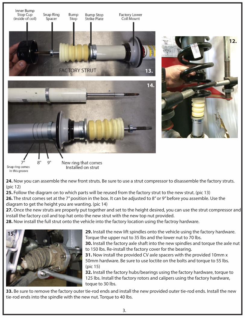
29. Install the new lift spindles onto the vehicle using the factory hardware.Torque the upper nut to 35 lbs and the lower nut to 70 lbs.30. Install the factory axle shaft into the new spindles and torque the axle nutto 150 lbs. Re-install the factory cover for the bearing.31. Now install the provided CV axle spacers with the provided 10mm x 50mm hardware. Be sure to use loctite on the bolts and torque to 55 lbs. (pic 15)32. Install the factory hubs/bearings using the factory hardware, torque to125 lbs. Install the factory rotors and calipers using the factory hardware, toque to 30 lbs.
12.
14.
13.
15.
33. Be sure to remove the factory outer tie-rod ends and install the new provided outer tie-rod ends. Install the newtie-rod ends into the spindle with the new nut. Torque to 40 lbs.

34. Install the sway bar drop brackets to the frame using the provided 10mm hardware. Torque to 25 lbs. (pic 16)35. Next, bolt the sway bar with the factory mounts to the new drop down brackets. Use the provided 7/16” x 2-1/4”hardware. Torque to 50 lbs. (pic 16)36. Install the provided sway bar extenders onto the end of the factory sway bar. (pic 17) The extender bracketinstalls on the bottom side of the sway bar with the larger side against the sway bar. Use the provided 18mmhardware. Torque to 110 lbs. Now install the factor sway bar end link into the factory location on the lower a-arm andinto the new extender bracket. (pic 18)
37. Install the new front brake line bracket extenders to the factory mount using the factory hardware. Then bolt thefactory bracket to the new extender bracket using the provided 1/4” hardware. (pic 19-20)38. Use the provided 1/4” x 3/4” hardware to bolt the factory brake hose and ABS line to the new lift spindle. Connectthe ABS line back together and use wire ties to secure the line out of the way. Besure there is enough slack for whenthe suspension travels.
39. Install the factory drive line into the factory di�erential just how it wasoriginally. Tighten all hardware and torque to factory specs. (pic 21)
4.
16.17.
18.
19. 20.
Picture #19 is the DRIVER SIDEBRAKE LINE BRACKET
Picture #20 is the PASSENGERSIDE BRAKE LINE BRACKET
21.

5.
REAR INSTALLATION With the vehicle turned o� and the parking brake set, secure the front wheels/tires with wheel chocks. Use a jack and lift the rear of the vehicle. Place jack stands under the frame on both side of the vehicle. Remove the rear wheels.
1. With the rear end supported, loosen the u-bolts on one side of thevehicle but do not remove. On theopposite side, remove those u-bolts fully and install the new lift blocksand provided u-bolts and hardware.Make sure the center pin is on the bottom of the block and �ts into the axle. The short side of the block willbe towards the front of the vehicle, with the long end towards the rear.2. Now install the lift block and u-bolts onto the opposide side of the vehicle making sure the block is aligned properly. (pic 1-2)3. Unbolt the factory bump stops. Use the provided the 10mm allen bolt to install the new bump stopextender and the factory bump stop.(pic 3)4. Using the provided self drilling hexhead screws. Re-route the factorybrake line bracket from the top of theframe to the underside of the frame.Be sure to check for clearance. (pic 4)5. Install the new rear lift shocks using the factory hardware.
6. Make sure the factory ABS line has enough slack so that when the rear end is at its fullest downward travel, the lineisn’t stretched. Wire tie the ABS line to the u-bolt and anywhere else needed to keep it out of the way.7. Take the driver side emergency brake cable out of the factory bracket and put the passenger side cable into itsplace. Bolt the bracket back in the same way it was originally installed using the factory hardware.8. Be sure to check the rear di�erential �uid. If it is not at the proper level, then �ll with the proper �uid.9. Double check all rear components, making sure there is plenty of clearance for all hoses, wires, and lines.10. Properly install wheels and tires and set vehicle on the ground. Check again for clearance on all brake lines.
1.
2.
3.
4.

* Double check all of the front and rear fasteners and components, making sure everything has been torqued to the proper specifications.This MUST be done before operating the vehicle.
* Vehicle MUST be properly aligned before driving.
* After 500 miles, be sure to go over all of the front and rear suspension and lift components to make sure nothing has come loose and every-thing is still tight.
* We recommend periodically checking all of the front and rear suspension and lift components to be sure they are tight and in proper working order.
6.
INSTALLATION NOTE:DO NOT remove the factory bumps stops in the front of the vehicle. They are located under the factory
upper control arms. These bump stops limit the travel of the suspension. If removed, it will allow the suspension to cycle farthar than the lift kit was designed to do.
Any removal or modi�cation of these bump stops in any way, will void all warranties on any componentin this lift kit.