Embed Size (px)
Citation preview

EXT-UHDV-HBTLS-TXEXT-UHDA-HBTL-RX
User ManualVersion A1
4K Ultra HD HDBaseT™ Multi-Format 2x1 Auto-Switching Sender w/ Scaler
Receiver w/ Audio-De-Embedder and POH

2
Important Safety Instructions
1. Read these instructions.
2. Keep these instructions.
3. Heed all warnings.
4. Follow all instructions.
5. Do not use this product near water.
6. Clean only with a dry cloth.
7. Do not block any ventilation openings. Install in accordance with the manufacturer’s instructions.
8. Do not install or place this product near any heat sources such as radiators, heat registers, stoves, or other apparatus (including amplifiers) that produce heat.
9. Do not defeat the safety purpose of the polarized or grounding-type plug. A polarized plug has two blades with one wider than the other. A grounding type plug has two blades and a third grounding prong. The wide blade or the third prong are provided for your safety. If the provided plug does not fit into your outlet, consult an electrician for replace-ment of the obsolete outlet.
10. Protect the power cord from being walked on or pinched particularly at plugs, convenience receptacles, and the point where they exit from the apparatus.
11. Only use attachments/accessories specified by the manufacturer.
12. To reduce the risk of electric shock and/or damage to this product, never handle or touch this unit or power cord if your hands are wet or damp. Do not expose this product to rain or moisture.
13. Unplug this apparatus during lightning storms or when unused for long periods of time.
14. Refer all servicing to qualified service personnel. Servicing is required when the apparatus has been damaged in any way, such as power-supply cord or plug is damaged, liquid has been spilled or objects have fallen into the apparatus, the apparatus has been exposed to rain or moisture, does not operate normally, or has been dropped.
15. Batteries that may be included with this product and/or accessories should never be exposed to open flame or excessive heat. Always dispose of used batteries according to the instructions.

3
Warranty Information
For the latest warranty coverage information, refer to the Warranty and Return Policy under the Connect section of the Gefen website at http://www.gefen.com/connect/warranty-and-return-policy

4
Contact Us
Technical Support
1-707-283-5900 1-800-472-5555 8:00 AM to 5:00 PM Monday - Friday, Pacific Time
Web
http://www.gefen.com
Mailing Address
GefenNortek Security & Control, LLCc/o Customer Service1800 S McDowell Blvd Petaluma, CA 94954 USA
© 2018 Noretk Security & Control, LLC. All Rights Reserved.
All trademarks are the property of their respective owners.
Gefen and Nortek Security & Control, LLC reserve the right to make changes in the hardware, packaging, and any accompanying documentation without prior notice.

5
Operating Notes
Important• While Unshielded (UTP) CAT-5e is usually adequate, shielded (STP) CAT-6A is recommended. Shielded (STP) CAT-5e or unshielded (UTP) CAT-5e or CAT- 6A may be acceptable depending on cable quality. Care should always be given to keep these cables away from power lines and other sources of electromagnetic interference.
• Cable quality is critical when handling 4K HDMI signals. We highly recommend Gefen HDMI cables. They have been designed and tested to reliably transport the the full throughput of HDMI standard.
• Power Over HDBaseT (POH) is a standard HDBaseT™ implementation of PoE that provides power from one device to the other over the link cable. This Sender and Receiver units comply with the POH standard. The EXT-UHDV-HBTLS-TX Sender can power the EXT-UHDA-HBTL-RX the Receiver, or the EXT-UHDA-HBTL-RX Receiver unit can power the EXT-UHDV-HBTLS-TX Sender.
• The EXT-UHDV-HBTLS-TX and the EXT-UHDA-HBT-RX, wehen used together, can pass both HDCP 2.2 and 1.4.
• The information in this manual has been carefully checked and is believed to be accurate. However, Gefen and Core Brands, LLC assume no responsibility for any inaccuracies that may be contained in this manual. In no event will Gefen and Core Brands, LLC be liable for direct, indirect, special, incidental, or consequential damages resulting from any defect or omission in this manual.
• All information contained herein is subject to change without notice.

6
This product may use software that is subject to open source licenses, including one or more of the General Public License Version 2 and Version 2.1, Lesser General Public License Version 2.1 and Version 3, BSD, and BSD-style licenses. Distribution and use of this product is subject to the license terms and limitations of liability provided in those licenses. Specific license terms and Copyright Notifications are provided in the source code. For three years from date of activation of this product, any party may request, and we will supply, for software covered by an applicable license (e.g. GPL or LGPL), a complete machine-readable copy of the corresponding open source code on a medium customarily used for software interchange. The following software and libraries are included with this product and subject to their respective open source licenses:
• lwIP• jQuery
lwIP is licenced under the BSD licence:
Copyright (c) 2001-2004 Swedish Institute of Computer Science.All rights reserved.
Redistribution and use in source and binary forms, with or without modification,are permitted provided that the following conditions are met:
1. Redistributions of source code must retain the above copyright notice, this list of conditions and the following disclaimer.
2. Redistributions in binary form must reproduce the above copyright notice, this list of conditions and the following disclaimer in the documentation and/or other materials provided with the distribution.
3. The name of the author may not be used to endorse or promote products derived from this software without specific prior written permission.
THIS SOFTWARE IS PROVIDED BY THE AUTHOR ` AS IS’’ AND ANY EXPRESS OR IMPLIED WARRANTIES, INCLUDING, BUT NOT LIMITED TO, THE IMPLIED WARRANTIES OF MERCHANTABILITY AND FITNESS FOR A PARTICULAR PURPOSE ARE DISCLAIMED. IN NO EVENT SHALL THE AUTHOR BE LIABLE FOR ANY DIRECT, INDIRECT, INCIDENTAL, SPECIAL, EXEMPLARY, OR CONSEQUENTIAL DAMAGES (INCLUDING, BUT NOT LIMITED TO, PROCUREMENT OF SUBSTITUTE GOODS OR SERVICES; LOSS OF USE, DATA, OR PROFITS; OR BUSINESS INTERRUPTION) HOWEVER CAUSED AND ON ANY THEORY OF LIABILITY, WHETHER IN CONTRACT, STRICT LIABILITY, OR TORT (INCLUDING NEGLIGENCE OR OTHERWISE) ARISING IN ANY WAY OUT OF THE USE OF THIS SOFTWARE, EVEN IF ADVISED OF THE POSSIBILITY OF SUCH DAMAGE.
Licensing

7
EXT-UHDV-HBTLS-TX*• HDMI Input supports 600 MHz TMDS Clock and data throughput of up to 18 Gbps (4K
Ultra HD (3840 x 2160) or 4K Cinema-DCI (4096 x 2160) up to 60 Hz, 4:4:4)
• Extension system supports 340 MHz TMDS Clock and data throughput of up to 10.2 Gbps
• Automatic switching of HDMI and VGA inputs
• Manual switching of HDMI and VGA inputs via front panel button or RS-232
• HDMI and VGA scaling up to 4K Ultra HD 3840 x 2160 @ 30 Hz, 4:4:4)
• VGA Phase and Clock adjustments
• Extend HDMI, VGA with analog audio, and RS-232 over a single CAT-5e:
4K Ultra HD (3840 x 2160 @ 30 Hz, 4:4:4), up to 130 ft/40 m, 8-bit color
4K Cinema (DCI) (4096 x 2160 @ 30 Hz 4:4:4), up to 130 ft/40 m, 8-bit color
1080p Full HD (60 Hz) or WUXGA (1920x1200 @ 60 Hz), up to 230 ft/70 m (up to 12-bit Deep Color)
• HDMI Features Supported:
HDMI 2.0
HDCP 2.2 and 1.4
12-bit Deep Color (at 1080p)
LPCM 7.1, Dolby Atmos®, Dolby® TrueHD, DTS:X™, and DTS-HD Master Audio™ pass- through
3DTV pass-through
CEC pass-through
Lip Sync pass-through
• Analog L/R audio input for VGA
• RS-232 control of switching, scaler, and EDID management functions
• Bi-Directional RS-232 extension when used with EXT-UHDA-HBTL-RX
• 2-way IR extension when used with EXT-UHDA-HBTL-RX
• Bi-Directional Power over HDBaseT™ (POH) provides power from the Sender to the Receiver or vice-versa, over the link cable. Only one side needs external power
• Uses Gefen’s implementation of HDBaseT™ technology with enhanced features
• Advanced EDID Management for rapid integration of source and display
• Field-updateable firmware via USB Micro-B and RS-232 ports, using the Gefen Syner-G™ software
• Locking power connector
• Compact, ultra-low-profile enclosure is surface-mountable and can be hidden away *Features and specifications are subject to change without notice.
All trademarks and registered trademarks are properties of their respective owners.
Features

8
EXT-UHDA-HBTL-RX*• Supports 340 MHz TMDS Clock and data throughput of up to 10.2 Gbps
• Extends HDMI, 2-way IR, and RS-232 over a single CAT-5e:
4K Ultra HD (3840 x 2160 @ 60 Hz, 4:2:0), up to 130 ft/40 m (8-bit color)
4K Ultra HD (3840 x 2160 @ 30 Hz, 4:4:4), up to 130 ft/40 m (8-bit color)
4K Cinema-DCI (4096 x 2160 @ 24 or 30 Hz 4:4:4), up to 130 ft/40 m (8-bit color)
1080p Full HD (60 Hz) or WUXGA (1920x1200 @ 60 Hz), up to 230 ft/70 m (up to 12-bit Deep Color)
• HDMI Features Supported:
HDMI 2.0
HDCP 2.2 and 1.4
12-bit Deep Color (at 1080p)
LPCM 7.1, Dolby Atmos®, Dolby® TrueHD, DTS:X™, and DTS-HD Master Audio™ pass- through
3DTV pass-through
CEC pass-through
Lip Sync pass-through
• RS-232 control of switching, scaler, and EDID management functions of a compatible Sender (such as EXT-UHDV-HBTLS-TX or EXT-UHDV-WP-HBTLS-TX)
• Bi-Directional RS-232 extension when used with a compatible Sender
• 2-way IR extension when used with EXT-UHDV-HBTLS-TX
• Digital (optical and coaxial) and Analog audio breakout
• Bi-Directional Power over HDBaseT™ (POH) provides power to the Receiver or a compatible Sender unit over the link cable - only one side will need external power
• Uses Gefen’s implementation of HDBaseT™ technology with enhanced features
• Locking power connector
• Compact, ultra-low-profile enclosure is surface-mountable and can be hidden away
*Features and specifications are subject to change without notice.
All trademarks and registered trademarks are properties of their respective owners.
Features

9
EXT-UHDV-HBTLS-TX*
The following items are included in the EXT-UHDV-HBTLS-TX package. If any of these items are not present in the box when you first open it, please contact Gefen Technical Support as soon as possible.
(1) 4K Ultra HD Multi-Format 2x1 HDBaseT™ Sender unit (1) 12V DC power supply with locking connector (1) 3-pin Phoenix plug (attached to unit) (2) Mounting Brackets (4) Self-adhesive rubber feet (1) Quick Start Guide
EXT-UHDA-HBTL-RX*
The following items are included in the EXT-UHDA-HBTL-RX. If any of these items are not present in the box when you first open it, please contact Gefen Technical Support as soon as possible.
(1) 4K Ultra HD HDBaseT™ Receiver unit (1) 12V DC power supply with locking connector (1) 3-pin Phoenix plug (attached to unit) (2) Mounting Brackets (4) Self-adhesive rubber feet (1) Quick-Start Guide
*Features and specifications are subject to change without notice.
All trademarks and registered trademarks are properties of their respective owners.
Packing Lists

10
Table of Contents
Controls, Connectors, and Indicators ............................................................................ 11EXT-UHDV-HBTLS-TX ...........................................................................................................11EXT-UHDA-HBTL-RX ............................................................................................................ 14
Installation .....................................................................................................................17Physical Installation, EXT-UHDV-HBTLS-TX ..................................................................... 17Physical Installation, EXT-UHDA-HBTL-RX ....................................................................... 17Sample Wiring Diagram ....................................................................................................... 18
LED Status ...................................................................................................................... 19
Scaler Functions and Picture Adjustments .................................................................20
EDID Management ....................................................................................................... 21
OSD ................................................................................................................................. 22OSD Buttons ..........................................................................................................................22OSD Operation ......................................................................................................................22OSD Options .......................................................................................................................... 23
RS-232 ............................................................................................................................29Features ..............................................................................................................................29Commands ............................................................................................................................ 32
IR Control ....................................................................................................................... 34Controlling the Source from the Viewing Location .............................................................34Controlling the Display from the Source Location .............................................................. 35Controlling the Source & Display from the Head-End and Viewing Locations 36
Firmware Update .......................................................................................................... 37
Specifications ................................................................................................................ 38

11
EXT-UHDV-HBTLS-TX
Controls, Connectors, and Indicators
Aut o VGAHDM IPowe r
Volum e
Inpu t Menu
4K Ultra HD Multi-Format 2x1 HDBaseT™ Sender w/ Scaler, Auto-Switching & POH
Firmware
1 2 3 4 5 6 7 8 9
12V DCLine In VGA InHDMI In IR Out
RS232
IR In/Ext
Tx G RxEXT-UHDV-HBTLS-TX
HDBaseT™ Out
10 11 12 13 14 15 16 17
ID Name Description
1 Power Indicator This LED indicator glows solid blue when the unit is powered. See LED Status (Page 19) for more information.
2 Auto Indicator This LED glows solid green when Auto-Switching is active. See LED Status (Page 19) for more information.
3 HDMI Indicator This LED indicator glows solid green when the HDMI input has been selected. See LED Status (Page 19) for more information.
4 VGA Indicator This LED indicator glows solid green when the VGA input has been selected. See LED Status (Page 19) for more information.
5 Input/Auto Switch To switch between HDMI and VGA inputs, press and release this button. To activate or deactivate Auto-Switching, press and hold this button for 3 seconds or longer until the function engages or disengages. The Auto LED (see 2 above) will be illuminated when Auto-Switching is active. See LED Status (Page 19) for more information.
6 Volume Down Button Press and release this button to decrease audio output. Press both Volume Up and Volme Down buttons simultaneously to mute the audio. Press Volume Up or Volume Down buttons to unmute.

12
Controls, Connectors, and Indicators
ID Name Description
7 Volume Up Button Press and release this button to increase audio output. Press both Volume Up and Volme Down buttons simultaneously to mute the audio. Press Volume Up or Volume Down buttons to unmute.
8 Menu Button Press and release the Menu button to enter and exit the On-Screen-Display (OSD).
9 Firmware Update Port To do a firmware update, attach a USB thumb drive containing the new firmware to this port, using a USB Micro-B male to USB Type-A female cable or adaptor. The Gefen Syner-G™ software, running on a PC connected to the RS-232 port of the Sender unit (Page 28) will administer the firmware update process.
10 HDMI Input Connect a Gefen HDMI cable from your source to this input.
11 VGA Input Connect a VGA cable from your source to this input.
12 VGA Audio Input Connect a 3.5mm stereo audio cable from the analog stereo audio output of your source to be used with the VGA input.
13 IR In/Ext 3.5mm mini-stereo jack. Connect an IR Extender (Gefen part no. EXT-RMT-EXTIRN) to this port. Alternatively, connect a 3.5mm mini-stereo connector from this port to the output of an automation system with an electrical IR output.
14 IR Out Connect an EXT-IREMIT IR Emitter (1 pc included) from this port to the IR sensor of the device to be controlled.
15 RS-232 Port This port can be used for extending 2-way RS-232 communications between the Sender and the Receiver, for remote control of the Sender, for Gefen Syner-G™ interface using an Rs-232 connection with a computer. Connect Tx, Rx, and Ground from an automation control device or an RS-232 device-to-be-controlled, using the removable 3-pin “Captive Screw” Phoenix connector.
13
Controls, Connectors, and Indicators
ID Name Description
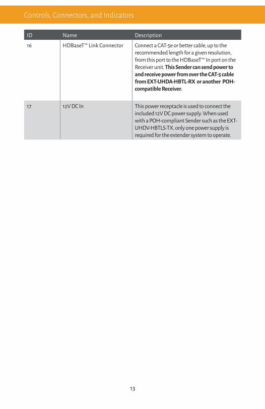
16 HDBaseT™ Link Connector Connect a CAT-5e or better cable, up to the recommended length for a given resolution, from this port to the HDBaseT™ In port on the Receiver unit. This Sender can send power to and receive power from over the CAT-5 cable from EXT-UHDA-HBTL-RX or another POH- compatible Receiver.
17 12V DC In This power receptacle is used to connect the included 12V DC power supply. When used with a POH-compliant Sender such as the EXT-UHDV-HBTLS-TX, only one power supply is required for the extender system to operate.

14
5
EXT-UHDA-HBTL-RX
Powe rLink HDCP
Prog 1 Prog 2
RS-232 Pass-Thru
Tx G RxRS-23 2
IR In/Ex t IR Out HDM I Out
Audi o OutLine Coax Optical HDBaseT ™ In 12V DC
EXT-UHDA-HBTL-RX4321
6 7 8 9 10 11 12 13
ID Name Description
1 RS-232/Program Switch This 3-position slide switch places the unit in RS-232 extension or factory service modes (Prog 1 and Prog 2). During normal operation, this switch should be in RS-232 Pass-Thru position.
2 Link Indicator This LED glows solid green when a link is established between the Sender and Receiver. See LED Status (Page 19) for more information.
3 HDCP Indicator This LED indicator glows solid green when the active HDMI signal contains HDCP encryption. See LED Status (Page 19) for more information.
4 Power Indicator This LED indicator glows solid blue when the unit is powered. See LED Status (Page 19) for more information.
Controls, Connectors, and Indicators

15
Controls, Connectors, and Indicators
ID Name Description
5 RS-232 Port This port can be used for extending 2-way RS-232 communications between the Sender and the Receiver, for remote control of the Sender, for Gefen Syner-G™ interface using an Rs-232 connection with a computer. Connect Tx, Rx, and Ground from an automation control device or an RS-232 device-to-be-controlled, using the removable 3-pin “Captive Screw” Phoenix connector. Please note that The Sender and Receiver’s Tx, Rx, and Ground pin-outs for their Phoenix connectors are different. To ensure proper operation, please follow the pin-out of each connector as printed on each unit’s enclosure.
6 IR In/Ext 3.5mm mini-stereo jack. Connect an IR Extender (Gefen part no. EXT-RMT-EXTIRN) to this port. Alternatively, connect a 3.5mm mini-stereo connector from this port to the output of an automation system with an electrical IR output.
7 IR Out Connect an EXT-IREMIT IR Emitter (sold separately) from this port to the IR sensor of the device to be controlled.
8 HDMI Out Use a Gefen HDMI cable to connect an HDMI display to this port.
9 Line Out This port provides analog Left and Right channels of audio de-embedded from the HDMI signal, for use with outboard amplification. Connect a 3.5mm stereo audio cable from this port to the analog stereo input of your amplifier or processor.
16
Controls, Connectors, and Indicators
ID Name Description
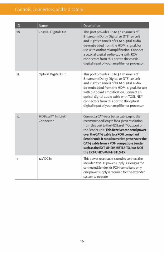
10 Coaxial Digital Out This port provides up to 5.1 channels of Bitstream (Dolby Digital or DTS), or Left and Right channels of PCM digital audio de-embedded from the HDMI signal, for use with outboard amplification. Connect a coaxial digital audio cable with RCA connectors from this port to the coaxial digital input of your amplifier or processor.
11 Optical Digital Out This port provides up to 5.1 channels of Bitstream (Dolby Digital or DTS), or Left and Right channels of PCM digital audio de-embedded from the HDMI signal, for use with outboard amplification. Connect an optical digital audio cable with TOSLINK® connectors from this port to the optical digital input of your amplifier or processor.
12 HDBaseT™ In (Link) Connector
Connect a CAT-5e or better cable, up to the recommended length for a given resolution, from this port to the HDBaseT™ Out port on the Sender unit. This Receiver can send power over the CAT-5 cable to a POH compliant Sender unit. It can also receive power over the CAT-5 cable from a POH compatible Sender such as the EXT-UHDV-HBTLS-TX, but NOT the EXT-UHDV-WP-HBTLS-TX.
13 12V DC In This power receptacle is used to connect the included 12V DC power supply. As long as the connected Sender ids POH-compliant, only one power supply is required for the extender system to operate.

17
InstallationPhysical Installation
EXT-UHDA-HBTLA-TX:
1. The Sender’s ultra-low-profile enclosure can be surface-mounted using a pair of mount-ing brackets that can be attached to each side of the enclosure using the provided screws. It can also be placed on a shelf.
2. When surface-mounting the Sender, please secure it to the mounting surface using screws appropriate for that specific surface (not included with the product).
EXT-UHDA-HBTL-RX:
1. The Receiver’s ultra-low-profile enclosure can be hidden behind the display. It also fea-tures a pair of mounting brackets that can be attached to each side of the enclosure using the provided screws.
2. When surface-mounting the Receiver, please secure it to the mounting surface using screws appropriate for that specific surface (not included with the product).

18
Installation
Notes1. The wiring diagram above shows cables and accessories that may not be included with the products. Select accessories (as identified by Gefen part numbers) are available for purchase from your Gefen distributor.
2. Power supply connections are not shown in the diagrams above.
Sample Wiring Diagram
EXT-UHDA-HBTL-RX
VGA CABLE
4K Ultra HD Source
EXT-UHDV-HBTLS-TXSender (Back)
VGA Source
RS-232 AutomationControl Device
or Device-To-Be-Controlled
RS-232 AutomationControl Device
or Device-To-Be-Controlled
Display
Powered Speakersor Audio Amplifier
w/analog L/R input
Audio Amplifierw/ coaxial digital input
Audio Amplifierw/ optical digital input
HDMI CABLE
RS-232 CABLE
CAT-5e CABLE
3.5MM AUDIO CABLEOPTICAL DIGITAL AUDIO
IR INIR OUT
COAXIAL DIGITAL AUDIO
EXT-UHDA-HBTL-RXReceiver (Back) 12V DCLine In VGA InHDMI In IR Out
RS232
IR In/Ext
Tx G RxEXT-UHDV-HBTLS-TX
HDBaseT™ Out
IR Extender for source control
IR Emitter to display
IR Extender
for display control
IR Emitter to sources
EXT-UHDV-HBTLS-TX

19
Off • The unit is not powered. Check the power supply and the Link connection between the Sender and the Receiver unit.
LED StatusThe Power, Auto, HDMI, and VGA indicators on the Sender, and Power, Link, and HDCP indicators on the Receiver unit provide basic information on the current status of each unit.
Power Description
Solid blue • The unit is powered.
Link (Receiver only) Description
Solid green • Link integrity is good between the Sender and Receiver unit.
Off • Link is not detected. Check the power supply and the Link connection between the Sender and the Receiver unit.
HDMI (Sender only) Description
Solid green • HDMI Input is selected.
Off • VGA input is selected.
HDCP (Receiver only) Description
Solid green • The HDMI signal being extended between Sender and Receiver has HDCP Encryption.
Off • Either the VGA or an unencrypted HDMI signal is being extended.
VGA (Sender only) Description
Solid green • VGA Input is selected.
Off • HDMI input is selected.
Auto* (Sender only) Description
Solid green • Automatic Input Switching is active.
Off • Automatic Input Switching is off.
* To Enable/Disable Auto-Switching, press and hold the Input/Auto Button for 3 seconds or longer until the backlight turns on or off.

20
Scaler Functions and Picture Adjustments The EXT-UHDV-HBTLS-TX features a powerful Scaler that is always active for both HDMI and VGA inputs. The input signal can be scaled to an array of resolutions, timing, and aspect ratio up to 4K Ultra HD (3840 x 2160) at 30 Hz, 4:4:4.
Output aspect ratio automatically follows the source to maintain the best possible picture at all times.
Scaler Output can be set to one of the following:
1 - 1024x768 60 Hz2 - 1280x720 50 Hz3 - 1280x720 60 Hz4 - 1360x768 60 Hz5 - 1920x1080 50 Hz6 - 1920x1080 60 Hz7 - 3840x2160 30 Hz
The EXT-UHDV-HBTLS-TX also features VGA Clock and Phase adjustments.
All of the above scaler and picture adjustment parameters can be configured via RS-232 commands (Page 26) or Gefen Syner-G™ software.

21
EDID Managemnent The EXT-UHDV-HBTLS-TX also features advanced EDID Management capabilities for quick optimization of a source’s output to best match the display’s capabilities.
EDID Management can be done via RS-232 commands (Page 26) or using the Gefen Syner-G™ software.
When using Gefen Syner-G™, Internal, External, and Custom EDIDs can be downloaded from the EXT-UHDV-HBTLS-TX, modified via the advanced EDID Editor that is built into the Gefen Syner-G™ software, and uploaded back into the Sender.

22
OSDThe EXT-UHDV-HBTLS-TX features an On-Screen Display (OSD) that can be used to configure options.
Use the front panel buttons on the EXT-UHDV-HBTLS-TX to activate/deactivate the OSD, navigate, and select options.
OSD Buttons:
ID Name
1 Down (<down>) Button
2 UP (<up>) Button
3 Menu Button
OSD Operation:
• OSD Activation: Press and release the MENU button on the front panel
• OSD Deactivation: The OSD will automatically deactivate if an input command (Menu, <up> or <down>) has not been detected in 5 seconds. This time-out is not adjustable.
• Navigation: Use the <up> button on the front panel to navigate to the option directly above the currently highlighted menu option. Conversely, use the <down> button to navigate to the option directly below the currently highlighted menu option.
• Select: Press and release the MENU button while the OSD is activated to navigate to the next menu layer or to select the currently highlighted option.
Aut o VGAHDM IPowe r
Volum e
Inpu t Menu
4K Ultra HD Multi-Format 2x1 HDBaseT™ Sender w/ Scaler, Auto-Switching & POH
Firmware
1 2 3

23
OSD
Main Menu
Resolution - Manage the built-in scaler’s output resolution. This option affects both the HDMI and VGA inputs.
EDID: Manage the EDID that is used with the HDMI input.
HDCP: Manage HDCP functions.
VGA: Manage VGA options, including the Auto-Sync feature.
System: Manage System options, such as Factory Default and RS-232 Baud Rate.
Exit: Leave the OSD.
OSD Options

24
Resolution Menu
Sets the output resolution for both the HDMI and VGA inputs. The following options are available:
3840x2160 30 Hz1920x1080 60 Hz1920x1080 50 Hz1280x720 60 Hz1280x720 50 Hz1360x768 60 Hz1024x768 60 Hz
Note: The signal from 4K (3840 x 2160 ) Ultra HD sources that operate at 60 Hz will automatically be converted to 3840 x 2160 30 Hz.
Back: Go back to the previous layer of the OSD.
OSD

25
EDID Menu
Sets the EDID that will be used with the HDMI input.
Selecting an EDID will aid in forcing a particular resolution/timing and audio format.
The following EDID options are available:
1080P 2CH: EDID with various CEA and VESA timings and a preferred timing of 1920x1080 60 Hz, progressive. Audio support is limited to 2 channels of LPCM (Front Left and Front Right channels), which is the maximum number of audio channels supported by this product.
4K UHD 300 MHz 2CH: EDID with various CEA and VESA timings and a preferred timing of 3840x2160 30 Hz, progressive. Audio support is limited to 2 channels of LPCM (Front Left and Front Right channels), which is the maximum number of audio channels supported by this product.
External: EDID that is transferred from the display/device connected to the Receiver at the remote location. Note that some resolutions/timings and audio formats that are available on the display/device connected to the Receiver may not be compatible with this product.
Custom: This EDID is user-managed and uploaded/managed from the Gefen Syner-G™ software. Note that some resolutions/timings and audio formats that are present in a user EDID may not be compatible with this product.
Back: Go back to the previous layer of the OSD.
Note: The VGA EDID is fixed and includes a number of standard VESA timings that are
OSD

26
HDCP Menu
Sets the HDCP operating mode for the HDMI input. The following HDCP operating modes are available:
HDCP Active: This HDCP operating mode will follow the detected HDMI input’s HDCP encryption level, if present. Acceptable HDCP encryption levels include HDCP 2.2 and HDCP 1.4. If the connected HDMI source is unencrypted, HDCP encryption will not be enforced on the Receiver’s HDMI output.
HDCP On: A minimum of HDCP 1.4 encryption will always be enforced on the Receiver’s HDMI output,m regardless of whertheer the iunput is encrypted or not. If HDCP encryption is detected on the HDMI input device, the same level of encryption will be active and enforced on the Receiver’s HDMI output.
Back: Go back to the previous layer of the OSD.
Note: HDCP 1.4 will also be active on the Receiver’s output if the VGA input is active and the HDCP operating mode is set to “HDCP On”.
OSD

27
VGA Menu
The VGA menu is used to adjust options that relate to the VGA input. The following options are available:
Auto-Sync: Enable and Disable the Auto-Sync feature. When this option is enabled, an Auto-Sync function will be performed when a VGA input is connected or the VGA input has been selected. Perform Auto-Sync: This option performs a manual Auto-Sync function on demand. This can be used regardless of whether the Auto-Sync feature is Enabled or Disabled.
VGA Phase: This option can be used fegardless of whether Auto-Sync is Enabled or Disabled. It is used to fine-tune the output image if the Auto-Sync function does not produce a perfectly clear image.
Back: Go back to the previous layer of the OSD.
OSD

28
System Menu
The System menu is used to modify options that relate to operational functions on the EXT-UHDV-HBTLS-TX. The following options are available:
RS-232 Baud Rate: Sets the operating baud rate for the RS-232 serial interface. The following options are available:
• 115200• 57600• 38400• 19200• 9600• 4800• 2400
Factory Default: Use this option to return the unit to factory default settings.
Firmware Version: Displays the current firmware version that is installed on the EXT-UHDV-HBTLS-TX.
Back: Go back to the previous layer of the OSD.
OSD

29
RS-232RS-232 Features
The EXT-UHDV-HBTLS-TX & EXT-UHDA-HBTL-RX, when used together, support the following RS-232-related functions:
a. Bi-directional RS-232 extension between Sender and Receiver.
b. Control of Sender’s input switching, scaler functions, and EDID mangement from the viewing side, via the Receiver’s RS-232 port. This can be done via an automation control device or the Gefen Syner-G™ software.
c. Gefen Syner-G™ interface via RS-232 ports of Sender and Receiver. Gefen Syner-G™ software is used for firmware updates and EDID management of the Sender.
Please see the RS-232 commands section (Page 26) on how to configure the Sender and Receiver to perform the above functions.
a. Bi-directional RS-232 extension between Sender and Receiver:
1. Connect RS-232 Tx, Rx, and Ground from an automation control device to the removable 3-pin “Captive Screw” Phoenix connector that is attached to the RS-232 port of the Sender unit. Each of the 3 pins is identified on the connector panel.
2. Make sure that the 3 position slide switch on the front panel of the Receiver is set to RS-232 Pass-Thru mode. Connect RS-232 Tx, Rx, and Ground from the device-to-be-controlled, to the removable 3-pin “Captive Screw” Phoenix connector that is attached to the RS-232 port of the Receiver unit. Each of the 3 pins is identified on the top panel, near the connector.
3. Since RS-232 is a bi-directional communications protocol, you can also connect the automation controller to the receiver and the device-to-be-controlled to the sender, depending on your application.

30
b. Control of Sender’s input switching, scaler functions, and EDID mangement from the viewing side, via the Receiver’s RS-232 port:
1. Connect RS-232 Tx, Rx, and Ground from a computer with a Serial (RS-232) port, or using a USB-to-RS-232 adapator, to the removable 3-pin “Captive Screw” Phoenix connector that is attached to the RS-232 port of the Sender unit. Each of the 3 pins is identified on the connector panel.
2. Establish Serial (RS-232) communications between the computer and the Sender unit. Send the #SET_RS232_MODE 2 command to the Sender to place it in “Remote-End-Control” mode. To revert the Sender to its default RS-232 extension mode, the RS-232 command #SET_RS232_MODE 1 needs to be sent from the Receiver.
3. Disconnect the PC from the Sender unit. Wire the Sender unit as needed and install it in its location.
4. Make sure that the 3 position slide switch on the front panel of the Receiver is set to RS-232 Pass-Thru mode. Connect RS-232 Tx, Rx, and Ground from an automation control device to the removable 3-pin “Captive Screw” Phoenix connector that is at-tached to the RS-232 port of the Receiver unit. Each of the 3 pins is identified on the top panel, near the connector.
5. Program your automation control decvice with the RS-232 control commands (Page 26) for the EXT-UHDV-HBTLS-TX. All commands sent to the RS-232 port of the Receiver unit will be extended to the Sender unit via the HDBaseT™ Link cable.
RS-232

31
c. Interface with Gefen Syner-G™ via RS-232 ports of Sender and Receiver.:
1. Direct interface with the Sender: Connect RS-232 Tx, Rx, and Ground from a computer with a Serial (RS-232 port), or using a USB-to-RS-232 adapator, to the removable 3-pin “Captive Screw” Phoenix connector that is attached to the RS-232 port of the Sender unit. Each of the 3 pins is identified on the connector panel. If the Sender was configured to be in “Remote-End-Control” mode (see section (b) on previous page), return it to its default mode by following step (2) of section (b).
2. Direct interface with the Receiver: Since the Receiver does not have any customizable features , it cannot be used with Gefen Syner-G™.
3. Interface with the Sender by connecting through the Receiver:
i. Place the Sender unit in “Remote-End-Control” mode (see section (b) on previous page for details). Wire the Sender unit as needed and install it in its location.
ii. Make sure that the 3 position slide switch on the front panel of the Receiver is set to RS-232 Pass-Thru mode.
iii. Connect RS-232 Tx, Rx, and Ground from a computer with a Serial (RS-232 port), or using a USB-to-RS-232 adapator, to the removable 3-pin “Captive Screw” Phoenix connector that is attached to the RS-232 port of the Receiver unit.
RS-232

32
RS-232
RS-232 Commands (EXT-UHDV-HBTLS-TX)

33
RS-232

34
Controlling the Source from the Viewing Location
1. Connect an EXT-RMT-EXTIRN IR Extender (sold separately) to the IR In/Ext port on the Receiver unit. If using an automation system, connect the 3.5mm mini-stereo connector from the IR In/Ext port on the Receiver unit to the IR Output port of the automation system. IR signals will be transmitted over the Link cable.
2. Connect an EXT-IREMIT IR Emitter (sold separately) from the IR Out port of the Sender unit, to the IR sensor window on the source device.
IR Control
4K Ultra HD Source EXT-UHDV-HBTLS-TXSender (Back)
VGA Source
EXT-UHDA-HBTL-RXReceiver (Back)
12V DCLine In VGA InHDMI In IR Out
RS232
IR In/Ext
Tx G RxEXT-UHDV-HBTLS-TX
HDBaseT™ Out
EXT-RMT-EXTIRNIR Extender
for source control
EXT-IREMITIR Emitter to sources
CAT-5e Link Cable
IR Signalto Sources
IR Signalto Sources
IR Signalto Sources
Third-Party Controller with Electrical IR Output
-OR-
IR Signalto Sources

35
IR Control
Controlling the Display from the Source Location
1. Connect an EXT-RMT-EXTIRN IR Extender (sold separately) to the IR In/Ext port on the Sender unit. If using an automation system, connect the 3.5mm mini-stereo connector from the IR In/Ext port on the Receiver unit to the IR Output of the automation system. IR signals will be transmitted over the Link cable.
2. Connect an EXT-IREMIT IR Emitter (sold separately) from the IR Out port on the Receiver unit to the IR sensor on the display.
EXT-UHDV-HBTLS-TXSender (Back)
EXT-UHDA-HBTL-RXReceiver (Back)
12V DCLine In VGA InHDMI In IR Out
RS232
IR In/Ext
Tx G RxEXT-UHDV-HBTLS-TX
HDBaseT™ Out
CAT-5e Link Cable
EXT-RMT-EXTIRNIR Extender for display
control
IR Signalto Display
IR Signalto Display
IR Signalto Display
DisplayIR Emitter to display
-OR-
Third-Party Controller with Electrical IR Output
IR Signalto Display

36
IR Control
Controlling the Source & Display from the Head-End and Viewing Locations
1. This set-up will require an additional EXT-RMT-EXTIRN and EXT-IREMIT, sold separately by your Gefen distributor.
2. Follow instructions on page 26 and 27.
4K Ultra HD Source EXT-UHDV-HBTLS-TXSender (Back)
VGA Source
EXT-UHDA-HBTL-RXReceiver (Back)
12V DCLine In VGA InHDMI In IR Out
RS232
IR In/Ext
Tx G RxEXT-UHDV-HBTLS-TX
HDBaseT™ Out
EXT-RMT-EXTIRNIR Extender
for source control
EXT-IREMITIR Emitter to sources
CAT-5e Link Cable
IR Signalto Sources
IR Signalto Sources
IR Signalto Sources
Third-Party Controller with Electrical IR Output
-OR-
IR Signalto Sources
EXT-RMT-EXTIRNIR Extender for display
control
IR Signalto Display
IR Signalto Display
IR Signalto Display
DisplayIR Emitter to display
-OR-
Third-Party Controller with Electrical IR Output
IR Signalto Display

37
Firmeware Update
Firmware Update
1. Over time, the Sender unit may require a firmware update to add functionality or fix issues.
2. To perform a firmware update, a Windows PC that is running the Gefen Syner-G™ software needs to be connected to to the RS-232 port of the Sender. Use direct RS-232 connection if your PC has a serial port. If not, use a USB-to-RS-232 adapator.
3. To update the Sender unit, the Gefen Syner-G™software will send the necessary commands to place the product in firmware update mode. The firmware will be loaded into the Sender from a USB thumb drive, connected to the Micro-USB Firmware port on the Sender’s front panel via a USB-Micro-B-male-to-USB-Type-A-female cable or adaptor (available from major electronics stores).
4. Follow on-screen instructions in Gefen Syner-G™ to perform the firmware update.
5. Once a unit has successfully been updated, cycle the power by removing power from the Sender unit, wait for the Power LED to deactivate, and then reconnect the power supply.

38
Supported Formats
HDMI InputMaximum Video Resolution/Timing
• 4K Cinema - DCI (4096 x 2160 to 60Hz, 4:4:4)• 4K Ultra HD (3840 x 2160 to 60Hz, 4:4:4)
VGA InputMaximum Video Resolution/Timing
• WUXGA (1920x1200 to 60 Hz 4:4:4)
HDBaseT ExtensionMaximum Video Resolution/Timing
• 4K Ultra HD (3840 x 2160 at 30Hz, 4:4:4)
Audio (HDMI Pass-Thru) • Up to 8 channels of HBR, Bitstream, & LPCM
HDCP • 2.2 and 1.4
Connectors & Indicators
Video Input Connectors • 1 x HDMI Type A 19-pin, female• 1 x VGA HD-15, female
L/R Analog VGA Audio Input Connector • 1 x 3.5mm mini-stereo jack
HDBaseT™ Link Connector • 1 x RJ-45, shielded
Firmware Update Connector • 1 x USB Micro-B, female
RS-232 Connector • 1 x 3-pin Phoenix
IR Extender Type • EXT-RMT-EXTIRN
IR In/Ext Connector • 1 x 3.5mm mini-stereo, female
IR Out Connector • 1 x 3.5mm mini-stereo, female
Power Connector • 1 x 12V DC, locking, 5.5mm barrel/2.1mm pin
Auto-Manual Switch • 1 x tact-type
Power Indicator • 1 x LED, blue
Auto (Switching) Indicator • 1 x LED, green
HDMI Indicator • 1 x LED, green
VGA Indicator • 1 x LED, green
Operational
HDMI Input TMDS Clock/Video Bandwidth • 600 MHz/18 Gbps
Extension TMDS Clock/Video Bandwidth • 340 MHz/10.2 Gbps
Power Consumption • Not powering a Receiver: 9W maximum• Powering a Receiver: 22W maximum
Operating Temperature • +32 to +122 °F (0 to +50 °C)
Operating Humidity • 5% to 90% RH, non-condensing
Storage Temperature • -4 to +185 °F (-20 to +85 °C)
Storage Humidity (RH) • 0% to 95% RH, non-condensing
MTBF • 50000 hours
Specifications*EXT-UHDV-HBTLS-TX

39
Physical
Dimensions (W x H x D, not including connectors)
Not including mounting brackets:• 7.7” x 0.93” x 4” (195mm x 24 x 100mm)Including mounting brackets:• 8.7” x 0.93” x 4” (221mm x 24 x 100mm)
Net Weight • 0.8 lbs (0.35 kg)
* Features and specifications are subject to change without notice. All trademarks and registered trademarks are properties of their respective owners. Copyright© 2018 Nortek Security & Control, LLC
Specifications*

40
Supported Formats
Maximum Video Output Resolution/Timing
Overall Capability: • 4K Cinema - DCI (4096 x 2160 to 60Hz, 4:2:0)• 4K Ultra HD (3840 x 2160 to 60Hz, 4:2:0)When used with EXT-UHDV-HBTLS-TX:• 4K Ultra HD (3840 x 2160 at 30Hz, 4:4:4)
Audio (HDMI Pass-Thru) • Up to 8 channels of HBR, Bitstream, & LPCM
Audio (De-Embedded) • Up to 6 channels of Bitstream, or 2 channels of LPCM
HDCP • 2.2 and 1.4
Connectors & Indicators
Video Output Connector • 1 x HDMI Type A 19-pin, female
De-Embedded Audio Output Ports • L/R Analog: 1 x 3.5mm mini-stereo jack• Coaxial Digital: 1 x RCA, female• Optical Digital: 1 x TOSLINK®
HDBaseT™ Link Connector • 1 x RJ-45, shielded
RS-232 Connector • 1 x 3-pin Phoenix
Firmware Update Connector • 1 x USB Micro-B, female
IR Extender Type • EXT-RMT-EXTIRN
IR In/Ext Connector • 1 x 3.5mm mini-stereo, female
IR Out Connector • 1 x 3.5mm mini-stereo, female
Power Connector • 1 x 12V DC, locking, 5.5mm barrel/2.1mm pin
RS-232/Program Switch • 1 x 3-position, slide-type
Power Indicator • 1 x LED, blue
Link Indicator • 1 x LED, green
HDCP Indicator • 1 x LED, green
Operational
TMDS Clock • 340 MHz
Video Bandwidth • 10.2 Gbps
Power Consumption • Not powering a Sender: 9W maximum• Powering a Sender: 22W maximum
Operating Temperature • +32 to +122 °F (0 to +50 °C)
Operating Humidity • 5% to 90% RH, non-condensing
Storage Temperature • -4 to +185 °F (-20 to +85 °C)
Storage Humidity (RH) • 0% to 95% RH, non-condensing
MTBF • 50000 hours
EXT-UHDA-HBTL-RX
Specifications*
41
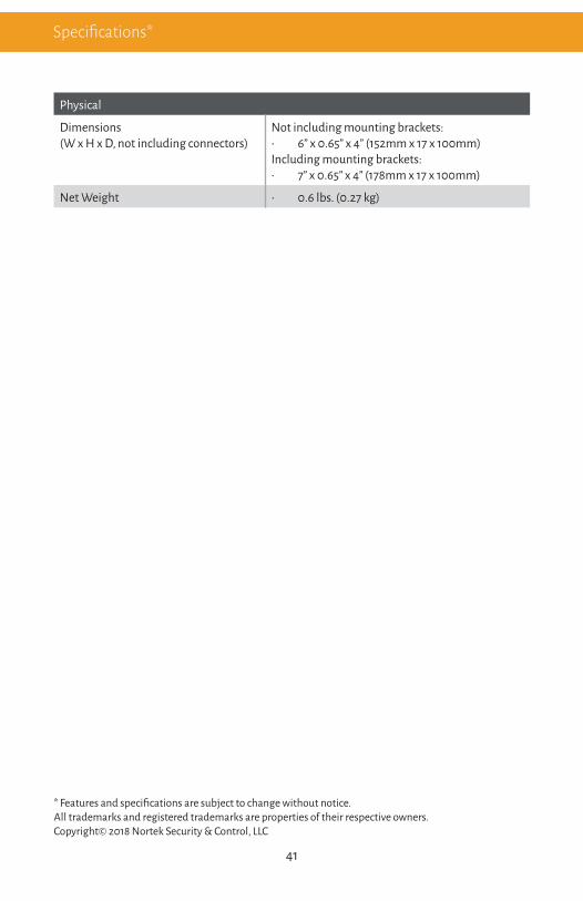
Physical
Dimensions (W x H x D, not including connectors)
Not including mounting brackets:• 6” x 0.65” x 4” (152mm x 17 x 100mm)Including mounting brackets:• 7” x 0.65” x 4” (178mm x 17 x 100mm)
Net Weight • 0.6 lbs. (0.27 kg)
* Features and specifications are subject to change without notice. All trademarks and registered trademarks are properties of their respective owners. Copyright© 2018 Nortek Security & Control, LLC
Specifications*

5919 Sea Otter Place, Suite 100 , Carlsbad, CA 92010, USA1800 S McDowell Blvd, Petaluma, CA 94954, USA
1-707-283-5900 1-800-472-5555Copyright© 2018 Nortek Security & Control, LLC
Part Number: MAN-EXT-UHDV-HBTLS Version A2