Embed Size (px)
Citation preview
48º CONGRESO ESPAÑOL DE ACÚSTICA ENCUENTRO IBÉRICO DE ACÚSTICA EUROPEAN SYMPOSIUM ON UNDERWATER ACOUSTICS APPLICATIONS EUROPEAN SYMPOSIUM ON SUSTAINABLE BUILDING ACOUSTICS
EXPERIMENTAL EVALUATION OF SOUND ABSORPTION OF MICROPERFORATED MDF PANELS
PACS no. 43.55.Ev PATRAQUIM, Ricardo1; GODINHO, Luís1; AMADO MENDES, Paulo1; PEREIRA, Matheus1; ABREU, Marcos2
1 ISISE, Departamento de Eng.ª Civil Universidade de Coimbra, Portugal Rua Luís Reis Santos, Pólo II da FCTUC, 3030-788 Coimbra, Portugal {[email protected], [email protected], [email protected],
[email protected]} 2 Departamento de Eng.ª Civil Universidade de Coimbra, Portugal Rua Luís Reis Santos, Pólo II da FCTUC, 3030-788 Coimbra, Portugal {[email protected]} ABSTRACT This work presents an experimental analysis of the acoustic behaviour of microperforated MDF panels. The experimental tests are performed over small specimens, using the impedance tube method (ISO 10534-2). The main objectives are the experimental evaluation of the efficiency of such solutions for different assembly conditions and the study of the influence of the size of the air cavity behind the panels and its filling with porous materials. The experimental results are also compared with theoretical models available in the literature. The results indicate that the tested solutions are efficient, with good sound absorption, and an interesting visual appearance.
Keywords: Wooden microperforated panels. Sound absorption. Impedance tube method ISO 10534-2. RESUMO Este trabalho apresenta uma análise experimental do comportamento acústico de painéis microperfurados em MDF. O estudo experimental foi realizado com provetes de pequena dimensão, utilizando o método do tubo de impedância (ISO 10534-2). O principal objetivo é avaliar a eficiência de tais soluções em função da montagem, estudar a influência da dimensão da caixa-de-ar no tardoz dos painéis e o preenchimento da mesma com materiais porosos. Os dados experimentais são ainda comparados com alguns resultados de modelos teóricos disponíveis na literatura. Os resultados indicam que as soluções testadas são eficientes, possuindo boa absorção sonora e um aspeto visual interessante.
Palavras-chave: Painéis microperfurados. Absorção sonora. Método tubo de impedância ISO 10534-2. 1. INTRODUCTION In order to control the reflections inside the rooms and to increase the sound absorption of their surfaces (ceilings and walls) it is usual to cover them with perforated wooden panels, leaving a cavity between them and the support surface, which may be, or not, filled with porous material. However, in some cases, due to the perforations of the panels, the visual appearance of the
panels is not considered adequate. If the dimensions of the perforations are considerably reduced, they become practically invisible when observed at a certain distance. When the perforations have dimension of the order of magnitude of the viscous boundary layer, i.e. submillimetric, energy dissipation is essentially due to the effects of air viscosity. In this way, the use of porous material can be avoided in the back air cavity, which allows the development of translucent (or even transparent) solutions. However, today, the search for new architectural solutions shows that it is of all interest to extend the concept of microperforation to traditional wood coatings. The concept of microperforated panels as sound absorber elements was explored in the seventies of the last century by Maa [1]. The main products developed were thin plates of the order of 1 mm, essentially metallic or acrylic (transparent or semi-transparent), with perforations smaller than 1 mm. They were used where the use of porous or fibrous materials was discouraged. The main advantage of using microperforated panels, besides the possibility of being transparent, is that they can present significant absorption in the low and medium frequencies. In the present work, the concept of microperforation is studied in wood panels whose thickness is no longer the typical one found in the original solutions. An experimental analysis of the behavior of microperforated panels in MDF is performed. The main objective is to complement the works presented by the authors [2] [3], to test the efficiency of such solutions with different assemblies, such as the size of the back air cavity, and the use of porous material in it. The experimental tests were performed in small samples using the impedance tube method ISO 10534-2 [4]. 2. MODELING SOUND ABSORPTION ON MICROPERFORATED PAN ELS 2.1 SOUND ABSORPTION COEFFICIENT
The sound absorption coefficient is defined by 2
1 R−=α , where R is the reflection
coefficient. For a given angle of incidence, iθ , this can be obtained from the acoustic
impedance of the surface, sZ ,
cos
cosS i C
S i C
Z ZR
Z Z
θθ
−=+
(1)
where cZ is the characteristic acoustic impedance of the propagation medium.
Thus, obtaining the sound absorption coefficient is based on the determination of the acoustic impedance presented by a sound absorber system. The surface acoustic impedance of a system with a microperforated panel is given by
interiorMPpanelsystem ZZZ += (2)
In order to determine interiorZ , the surface acoustic impedance of the existing system on the
back of the microperforated panel (e.g. empty air cavity or totally or partially filled by porous material), the transfer matrix concept is used to determine the surface acoustic impedance of an interface of a material, using the continuity of the velocity of the particle (on both sides of that interface) and knowing the acoustic properties of the medium. For more details on this modeling approach see [5]. 2.2 MODELING THE ACOUSTIC IMPEDANCE OF A MICROPERFO RATED PANEL The model adopted in the present work is based on the contributions of Maa [6], incorporating the corrections proposed by Ingard [7], Morse and Ingard [8] and Cremer and Muller [9]. The model proposed by Maa [6], developed from the works by Rayleigh [10] and later by Crandall [11], is based on the conversion of the acoustic impedance of a single hole into an average value corresponding to the open area of the panel, ε :
εtubes
MPpanelZ
Z = (3)
Consider the microperforated panel as a set of short tubes, of the same length as the panel thickness, and the non-perforated part made of a very dense and rigid material, and therefore perfectly reflective. It is further assumed that the wavelength of the propagating sound is large enough compared to the cross-sectional dimension of the tube (i.e., hole). According to [6, 10, and 11], the acoustic impedance of a circular tube of radius r and length
λ<0l is given by the expression:
( )( ) ( )
+−⋅+
++
+
−−−−=
−
30
22
00
1
0
100
47.047.113
16222
21
εεπ
ωρλ
πρηωρ
ρω
ri
rc
ixJix
ixJliZ
tubes (4)
with ηρω 0rx = , where ω is the angular frequency, 0ρ is the volumetric mass of air
( -3m kg 1.21=0ρ ) and η is the air viscosity ( poiseuille 10 x 1.84 -5≈η ). The last term of equation
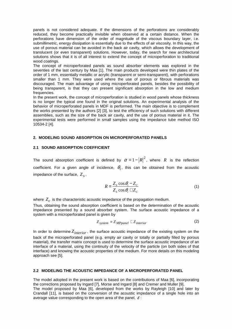
(4) corresponds to the corrective terms due to the air viscosity [7], the radiation (of a hole in a baffle) and the effects of the back air cavity reactance [8,9]. 3. TEST METHODOLOGY The experimental determination of the sound absorption coefficient in samples of reduced size was carried out using the impedance tube method, in accordance with ISO 10534-2 [4]. This method consists of the emission of a constant average intensity noise along the frequency spectrum, called white noise, in flat waves, with the aid of an amplifier and a loudspeaker. When the sound waves impinge on the sample, there are variations in pressure caused by the transformation of some of the sound energy incident to mechanical energy, which decreases the reflected sound pressure. These pressure variations are recorded by two microphones in predefined positions. The signals from the microphones are processed by a digital analyzer and, after being processed, the values of the sound absorption are obtained as a function of the frequency of the sound. The series of tests described in this paper make use of an impedance tube made of steel, following the recommendations of ISO 10534-2 [4] (Figure 1). The spacing between microphones is 0.05 m and the diameter of the tube is approximately 0.10 m. The distance between the nearest microphone and the sample surface is 0.25 m. Signal acquisition is accomplished through a NI USB 4431 acquisition system from National Instruments.
Figure 1: Pictures of the test equipment (impedance tube).
The entire test procedure followed in this work is described in more detail in Godinho et al [12].
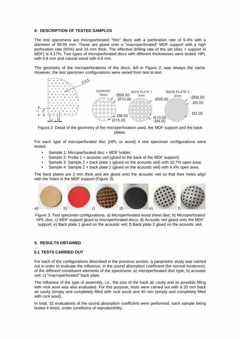
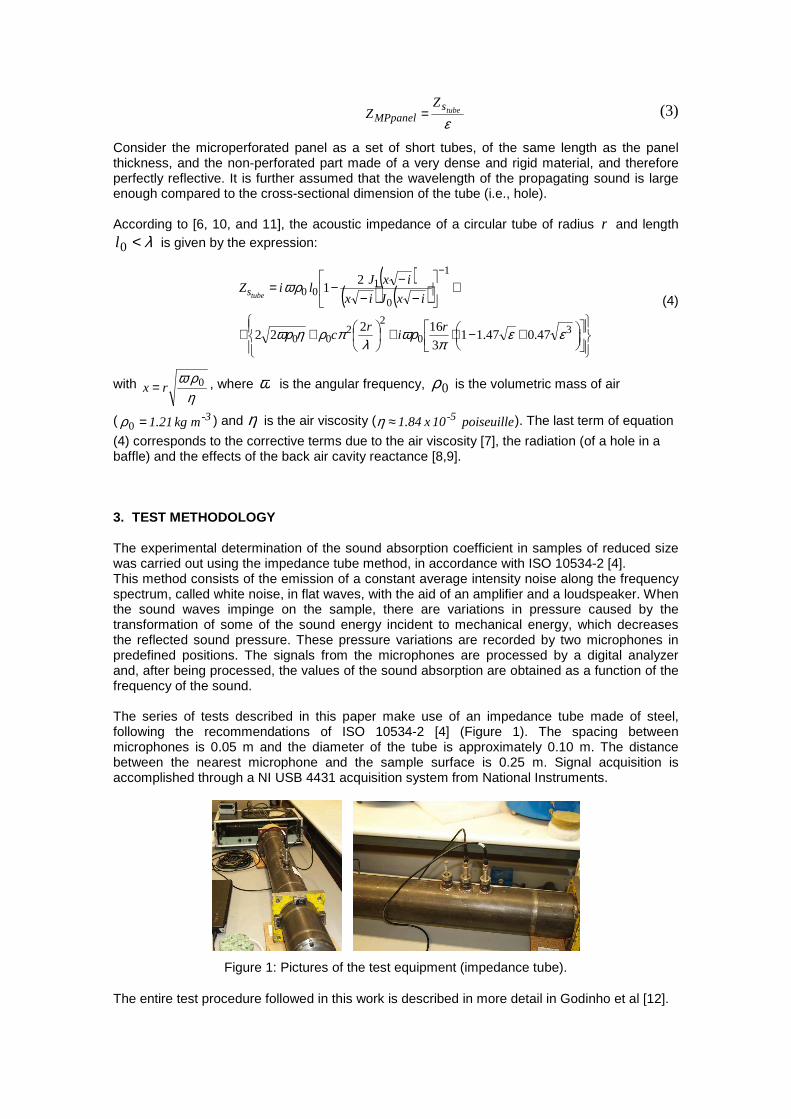
4. DESCRIPTION OF TESTED SAMPLES The test specimens are microperforated "thin" discs with a perforation rate of 6.4% with a diameter of 99.95 mm. These are glued onto a "macroperforated" MDF support with a high perforation rate (65%) and 16 mm thick. The effective drilling rate of the set (disc + support in MDF) is 4.17%. Two types of microperforated discs with different thicknesses were tested: HPL with 0.8 mm and natural wood with 0.6 mm. The geometry of the microperforations of the discs, left in Figure 2, was always the same. However, the test specimen configurations were varied from test to test.
Figura 2: Detail of the geometry of the microperforation used, the MDF support and the back plates.
For each type of microperforated disc (HPL or wood) 4 test specimen configurations were tested:
• Sample 1: Microperforated disc + MDF holder; • Sample 2: Probe 1 + acoustic veil (glued to the back of the MDF support); • Sample 3: Sample 2 + back plate 1 (glued on the acoustic veil) with 32.7% open area; • Sample 4: Sample 2 + back plate 2 (glued on the acoustic veil) with 8.4% open area.
The back plates are 3 mm thick and are glued onto the acoustic veil so that their holes align with the holes in the MDF support (Figure 3).
a) b) c) d) e) f)
Figure 3: Test specimen configurations: a) Microperforated wood sheet disc; b) Microperforated HPL disc; c) MDF support glued to microperforated discs; d) Acoustic veil glued onto the MDF support; e) Back plate 1 glued on the acoustic veil; f) Back plate 2 glued on the acoustic veil.
5. RESULTS OBTAINED
5.1 TESTS CARRIED OUT For each of the configurations described in the previous section, a parametric study was carried out in order to evaluate the influence, in the sound absorption coefficient (for normal incidence), of the different constituent elements of the specimens: a) microperforated disc type; b) acoustic veil; c) "macroperforated" back plate.
The influence of the type of assembly, i.e., the size of the back air cavity and its possible filling with rock wool was also evaluated. For this purpose, tests were carried out with a 20 mm back air cavity (empty and completely filled with rock wool) and 40 mm (empty and completely filled with rock wool).
In total, 32 evaluations of the sound absorption coefficient were performed, each sample being tested 4 times, under conditions of reproducibility.
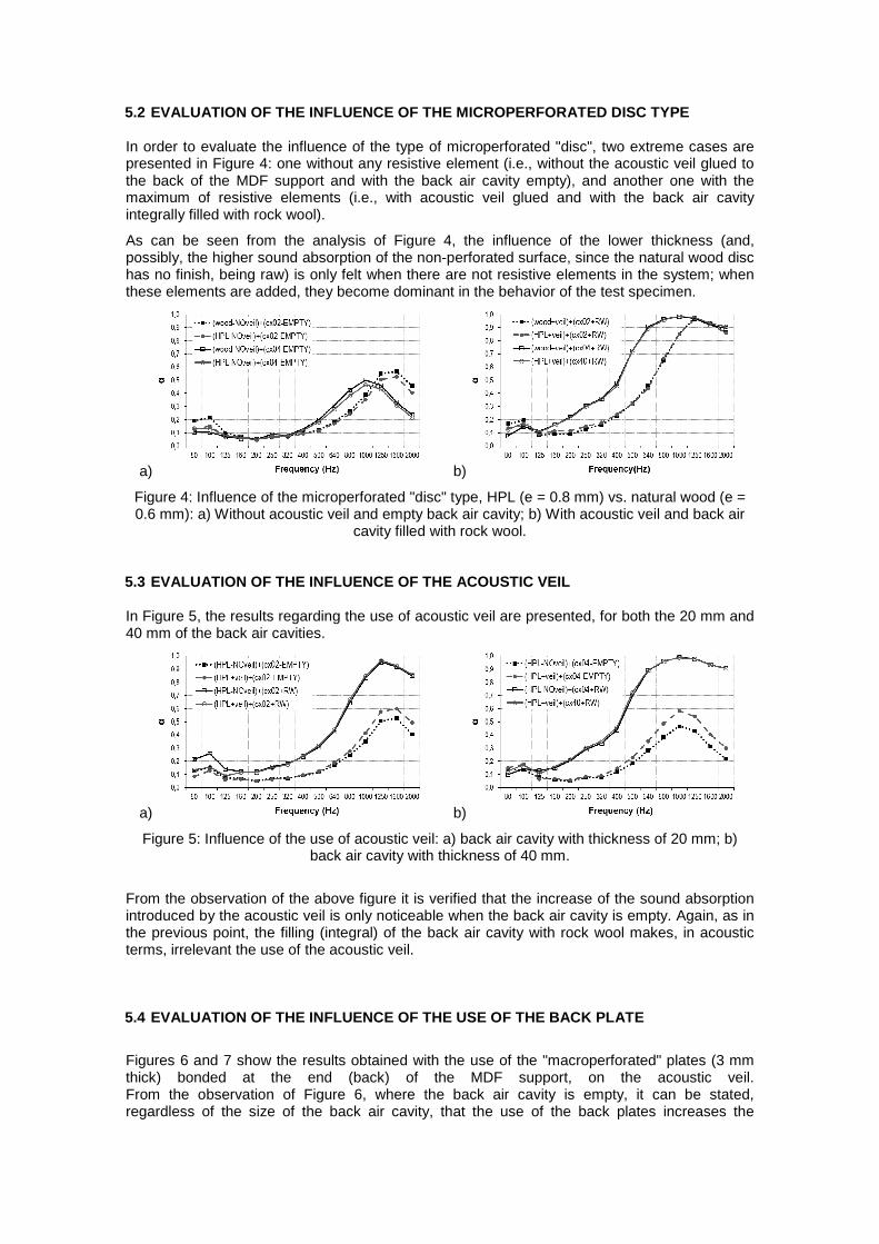
5.2 EVALUATION OF THE INFLUENCE OF THE MICROPERFOR ATED DISC TYPE In order to evaluate the influence of the type of microperforated "disc", two extreme cases are presented in Figure 4: one without any resistive element (i.e., without the acoustic veil glued to the back of the MDF support and with the back air cavity empty), and another one with the maximum of resistive elements (i.e., with acoustic veil glued and with the back air cavity integrally filled with rock wool).
As can be seen from the analysis of Figure 4, the influence of the lower thickness (and, possibly, the higher sound absorption of the non-perforated surface, since the natural wood disc has no finish, being raw) is only felt when there are not resistive elements in the system; when these elements are added, they become dominant in the behavior of the test specimen.
a) b)
Figure 4: Influence of the microperforated "disc" type, HPL (e = 0.8 mm) vs. natural wood (e = 0.6 mm): a) Without acoustic veil and empty back air cavity; b) With acoustic veil and back air
cavity filled with rock wool.
5.3 EVALUATION OF THE INFLUENCE OF THE ACOUSTIC VE IL In Figure 5, the results regarding the use of acoustic veil are presented, for both the 20 mm and 40 mm of the back air cavities.
a) b)
Figure 5: Influence of the use of acoustic veil: a) back air cavity with thickness of 20 mm; b) back air cavity with thickness of 40 mm.
From the observation of the above figure it is verified that the increase of the sound absorption introduced by the acoustic veil is only noticeable when the back air cavity is empty. Again, as in the previous point, the filling (integral) of the back air cavity with rock wool makes, in acoustic terms, irrelevant the use of the acoustic veil. 5.4 EVALUATION OF THE INFLUENCE OF THE USE OF THE BACK PLATE
Figures 6 and 7 show the results obtained with the use of the "macroperforated" plates (3 mm thick) bonded at the end (back) of the MDF support, on the acoustic veil. From the observation of Figure 6, where the back air cavity is empty, it can be stated, regardless of the size of the back air cavity, that the use of the back plates increases the
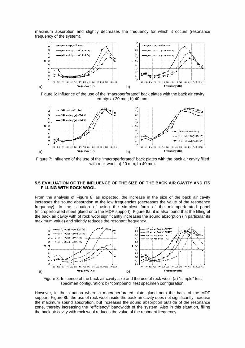
maximum absorption and slightly decreases the frequency for which it occurs (resonance frequency of the system).
a) b)
Figure 6: Influence of the use of the “macroperforated” back plates with the back air cavity empty: a) 20 mm; b) 40 mm.
a) b)
Figure 7: Influence of the use of the “macroperforated” back plates with the back air cavity filled with rock wool: a) 20 mm; b) 40 mm.
5.5 EVALUATION OF THE INFLUENCE OF THE SIZE OF THE BACK AIR CAVITY AND ITS
FILLING WITH ROCK WOOL From the analysis of Figure 8, as expected, the increase in the size of the back air cavity increases the sound absorption at the low frequencies (decreases the value of the resonance frequency). In the situation of using the simplest form of the microperforated panel (microperforated sheet glued onto the MDF support), Figure 8a, it is also found that the filling of the back air cavity with of rock wool significantly increases the sound absorption (in particular its maximum value) and slightly reduces the resonant frequency.
a) b)
Figure 8: Influence of the back air cavity size and the use of rock wool: (a) "simple" test specimen configuration; b) "compound" test specimen configuration.
However, in the situation where a macroperforated plate glued onto the back of the MDF support, Figure 8b, the use of rock wool inside the back air cavity does not significantly increase the maximum sound absorption, but increases the sound absorption outside of the resonance zone, thereby increasing the "efficiency" bandwidth of the system. Also in this situation, filling the back air cavity with rock wool reduces the value of the resonant frequency.
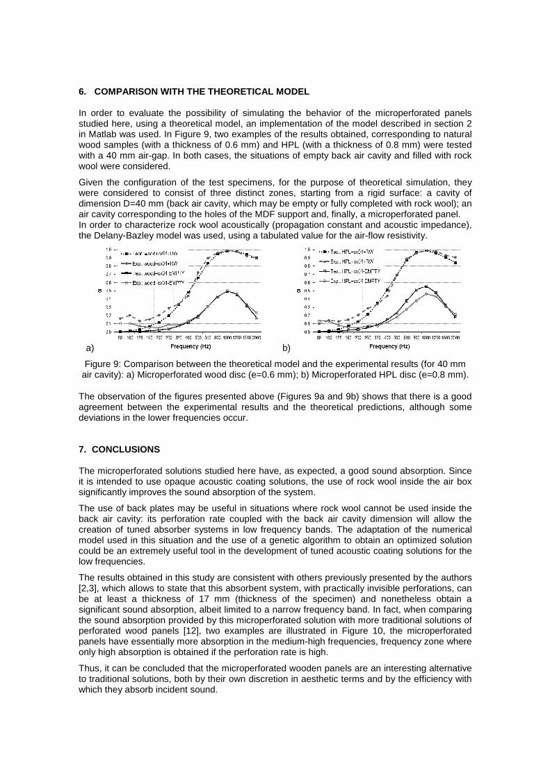
6. COMPARISON WITH THE THEORETICAL MODEL In order to evaluate the possibility of simulating the behavior of the microperforated panels studied here, using a theoretical model, an implementation of the model described in section 2 in Matlab was used. In Figure 9, two examples of the results obtained, corresponding to natural wood samples (with a thickness of 0.6 mm) and HPL (with a thickness of 0.8 mm) were tested with a 40 mm air-gap. In both cases, the situations of empty back air cavity and filled with rock wool were considered.
Given the configuration of the test specimens, for the purpose of theoretical simulation, they were considered to consist of three distinct zones, starting from a rigid surface: a cavity of dimension D=40 mm (back air cavity, which may be empty or fully completed with rock wool); an air cavity corresponding to the holes of the MDF support and, finally, a microperforated panel. In order to characterize rock wool acoustically (propagation constant and acoustic impedance), the Delany-Bazley model was used, using a tabulated value for the air-flow resistivity.
a) b)
Figure 9: Comparison between the theoretical model and the experimental results (for 40 mm air cavity): a) Microperforated wood disc (e=0.6 mm); b) Microperforated HPL disc (e=0.8 mm).
The observation of the figures presented above (Figures 9a and 9b) shows that there is a good agreement between the experimental results and the theoretical predictions, although some deviations in the lower frequencies occur. 7. CONCLUSIONS The microperforated solutions studied here have, as expected, a good sound absorption. Since it is intended to use opaque acoustic coating solutions, the use of rock wool inside the air box significantly improves the sound absorption of the system.
The use of back plates may be useful in situations where rock wool cannot be used inside the back air cavity: its perforation rate coupled with the back air cavity dimension will allow the creation of tuned absorber systems in low frequency bands. The adaptation of the numerical model used in this situation and the use of a genetic algorithm to obtain an optimized solution could be an extremely useful tool in the development of tuned acoustic coating solutions for the low frequencies.
The results obtained in this study are consistent with others previously presented by the authors [2,3], which allows to state that this absorbent system, with practically invisible perforations, can be at least a thickness of 17 mm (thickness of the specimen) and nonetheless obtain a significant sound absorption, albeit limited to a narrow frequency band. In fact, when comparing the sound absorption provided by this microperforated solution with more traditional solutions of perforated wood panels [12], two examples are illustrated in Figure 10, the microperforated panels have essentially more absorption in the medium-high frequencies, frequency zone where only high absorption is obtained if the perforation rate is high.
Thus, it can be concluded that the microperforated wooden panels are an interesting alternative to traditional solutions, both by their own discretion in aesthetic terms and by the efficiency with which they absorb incident sound.
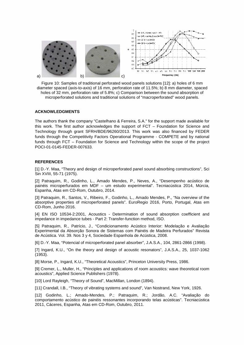
a) b) c)
Figure 10: Samples of traditional perforated wood panels solutions [12]: a) holes of 6 mm diameter spaced (axis-to-axis) of 16 mm, perforation rate of 11.5%; b) 8 mm diameter, spaced
holes of 32 mm, perforation rate of 5.8%; c) Comparison between the sound absorption of microperforated solutions and traditional solutions of “macroperforated” wood panels.
ACKNOWLEDGMENTS The authors thank the company "Castelhano & Ferreira, S.A." for the support made available for this work. The first author acknowledges the support of FCT – Foundation for Science and Technology through grant SFRH/BDE/96260/2013. This work was also financed by FEDER funds through the Competitivity Factors Operational Programme - COMPETE and by national funds through FCT – Foundation for Science and Technology within the scope of the project POCI-01-0145-FEDER-007633.
REFERENCES
[1] D.-Y. Maa, “Theory and design of microperforated panel sound absorbing constructions”, Sci Sin XVIII, 55-71 (1975).
[2] Patraquim, R., Godinho, L., Amado Mendes, P., Neves, A., “Desempenho acústico de painéis microperfurados em MDF – um estudo experimental”. Tecniacústica 2014, Múrcia, Espanha, Atas em CD-Rom, Outubro, 2014.
[3] Patraquim, R., Santos, V., Ribeiro, F., Godinho, L., Amado Mendes, P., “Na overview of the absorptive properties of microperforated panels”. EuroRegio 2016, Porto, Portugal, Atas em CD-Rom, Junho 2016.
[4] EN ISO 10534-2:2001, Acoustics - Determination of sound absorption coefficient and impedance in impedance tubes - Part 2: Transfer-function method, ISO.
[5] Patraquim, R., Patrício, J., “Condicionamento Acústico Interior: Modelação e Avaliação Experimental da Absorção Sonora de Sistemas com Painéis de Madeira Perfurados” Revista de Acústica. Vol. 39. Nos 3 y 4, Sociedade Espanhola de Acústica, 2008.
[6] D.-Y. Maa, “Potencial of microperforated panel absorber”, J.A.S.A., 104, 2861-2866 (1998).
[7] Ingard, K.U., “On the theory and design of acoustic resonators”, J.A.S.A., 25, 1037-1062 (1953).
[8] Morse, P., Ingard, K.U., “Theoretical Acoustics”, Princeton University Press, 1986.
[9] Cremer, L., Muller, H., “Principles and applications of room acoustics: wave theoretical room acoustics”, Applied Science Publishers (1978).
[10] Lord Rayleigh, “Theory of Sound”, MacMillan, London (1894).
[11] Crandall, I.B., “Theory of vibrating systems and sound”, Van Nostrand, New York, 1926.
[12] Godinho, L.; Amado-Mendes, P.; Patraquim, R.; Jordão, A.C. “Avaliação do comportamento acústico de painéis ressonantes incorporando telas acústicas”. Tecniacústica 2011, Cáceres, Espanha, Atas em CD-Rom, Outubro, 2011.