Embed Size (px)
Citation preview

GEDigital Energy
Instruction ManualProduct version: 4.0x
GE publication code: 1601-0150-AL (GEK-106494V)
489 GeneratorManagement Relay
1601-0150-AL

Copyright © 2014 GE Multilin Inc. All rights reserved.
489 Generator Management Relay Instruction Manual for version 4.0x.
489 Generator Management Relay, EnerVista, Digital Energy, Multilin, and GE Multilin are trademarks or registered trademarks of GE Multilin Inc.
The contents of this manual are the property of GE Multilin Inc. This documentation is furnished on license and may not be reproduced in whole or in part without the permission of GE Multilin. The content of this manual is for informational use only and is subject to change without notice.
Part number: 1601-0150-AL (December 2014)
TABLE OF CONTENTS
489 GENERATOR MANAGEMENT RELAY – INSTRUCTION MANUAL iii
Table of Contents1 INTRODUCTION Safety symbols and definitions....................................................................................1
For further assistance ...................................................................................................1
2 GETTING STARTED Important Procedures ...................................................................................................3Cautions and Warnings...............................................................................................................................3Inspection Checklist ......................................................................................................................................3Manual Organization ....................................................................................................................................4
Using the Relay ...............................................................................................................5Menu Navigation ............................................................................................................................................5Panel Keying Example..................................................................................................................................9
Changing Setpoints......................................................................................................11Introduction.................................................................................................................................................... 11The HELP Key................................................................................................................................................. 12Numerical Setpoints................................................................................................................................... 12Enumeration Setpoints ............................................................................................................................. 13Output Relay Setpoints ............................................................................................................................. 15Text Setpoints................................................................................................................................................ 16
Installation.....................................................................................................................18Placing the Relay in Service.................................................................................................................... 18Testing .............................................................................................................................................................. 18
3 INTRODUCTION Overview ........................................................................................................................19Description...................................................................................................................................................... 19Ordering........................................................................................................................................................... 22Other Accessories ....................................................................................................................................... 23
Specifications ................................................................................................................24Inputs ................................................................................................................................................................ 24Outputs............................................................................................................................................................. 25Protection........................................................................................................................................................ 26Digital Inputs.................................................................................................................................................. 29Monitoring....................................................................................................................................................... 30Power Supply................................................................................................................................................. 31Communications ......................................................................................................................................... 32Testing .............................................................................................................................................................. 32Approvals ........................................................................................................................................................ 33Physical ............................................................................................................................................................ 33Environmental...............................................................................................................................................34Long-term Storage ..................................................................................................................................... 35
4 INSTALLATION Mechanical Installation...............................................................................................37Description...................................................................................................................................................... 37Product Identification................................................................................................................................ 38Installation ...................................................................................................................................................... 39Unit Withdrawal and Insertion.............................................................................................................. 40Ethernet Connection .................................................................................................................................. 42Terminal Locations ..................................................................................................................................... 43
Electrical Installation...................................................................................................45Typical Wiring................................................................................................................................................ 45General Wiring Considerations ............................................................................................................. 46Control Power................................................................................................................................................ 46

iv 489 GENERATOR MANAGEMENT RELAY – INSTRUCTION MANUAL
TABLE OF CONTENTS
Current Inputs................................................................................................................................................47Voltage Inputs................................................................................................................................................50Digital Inputs ..................................................................................................................................................50Analog Inputs.................................................................................................................................................50Analog Outputs .............................................................................................................................................51RTD Sensor Connections ..........................................................................................................................51Output Relays ................................................................................................................................................52IRIG-B.................................................................................................................................................................53RS485 Ports.....................................................................................................................................................53Dielectric Strength.......................................................................................................................................54
5 INTERFACES Faceplate Interface ......................................................................................................57Display...............................................................................................................................................................57LED Indicators................................................................................................................................................57RS232 Program Port ...................................................................................................................................59Keypad ..............................................................................................................................................................59Setpoint Entry ................................................................................................................................................62Diagnostic Messages .................................................................................................................................64Self-Test Warnings ......................................................................................................................................64Flash Messages.............................................................................................................................................65
EnerVista Software Interface .....................................................................................66Overview ..........................................................................................................................................................66Hardware.........................................................................................................................................................66Installing the EnerVista 489 Setup Software...................................................................................68
Connecting EnerVista 489 Setup to the Relay.........................................................71Configuring Serial Communications ...................................................................................................71Using the Quick Connect Feature ........................................................................................................72Configuring Ethernet Communications.............................................................................................73Connecting to the Relay............................................................................................................................75
Working with Setpoints and Setpoint Files..............................................................77Engaging a Device.......................................................................................................................................77Entering Setpoints .......................................................................................................................................77Using Setpoint Files.....................................................................................................................................79
Upgrading Relay Firmware.........................................................................................85Description ......................................................................................................................................................85Saving Setpoints to a File .........................................................................................................................85Loading New Firmware.............................................................................................................................85
Advanced EnerVista 489 Setup Features .................................................................87Triggered Events...........................................................................................................................................87Waveform Capture (Trace Memory)....................................................................................................87Phasors .............................................................................................................................................................90Trending (Data Logger)..............................................................................................................................92Event Recorder..............................................................................................................................................95Modbus User Map........................................................................................................................................96Viewing Actual Values................................................................................................................................96
Using EnerVista Viewpoint with the 489 ..................................................................99Plug and Play Example ..............................................................................................................................99
6 SETPOINTS Overview ..................................................................................................................... 103Setpoint Message Map...........................................................................................................................103Trips / Alarms/ Control Features........................................................................................................108Relay Assignment Practices.................................................................................................................109Dual Setpoints ............................................................................................................................................110Commissioning...........................................................................................................................................110

TABLE OF CONTENTS
489 GENERATOR MANAGEMENT RELAY – INSTRUCTION MANUAL v
S1 489 Setup ............................................................................................................... 110Passcode ...................................................................................................................................................... 110Preferences ................................................................................................................................................. 111Communications ...................................................................................................................................... 113Real Time Clock ......................................................................................................................................... 114Default Messages..................................................................................................................................... 115Message Scratchpad.............................................................................................................................. 116Clear Data .................................................................................................................................................... 117
S2 System Setup ........................................................................................................ 119Current Sensing......................................................................................................................................... 119Voltage Sensing......................................................................................................................................... 119Generator Parameters ........................................................................................................................... 120Serial Start/Stop Initiation .................................................................................................................... 121
S3 Digital Inputs ........................................................................................................ 122Description................................................................................................................................................... 122Breaker Status ........................................................................................................................................... 122General Input A to G................................................................................................................................ 123Remote Reset ............................................................................................................................................. 124Test Input...................................................................................................................................................... 124Thermal Reset ............................................................................................................................................ 124Dual Setpoints............................................................................................................................................ 125Sequential Trip ........................................................................................................................................... 126Field-Breaker .............................................................................................................................................. 127Tachometer................................................................................................................................................. 127Waveform Capture .................................................................................................................................. 128Ground Switch Status............................................................................................................................. 128
S4 Output Relays ....................................................................................................... 129Description................................................................................................................................................... 129Relay Reset Mode ..................................................................................................................................... 129
S5 Current Elements ................................................................................................. 130Inverse Time Overcurrent Curve Characteristics....................................................................... 130Overcurrent Alarm ................................................................................................................................... 134Offline Overcurrent .................................................................................................................................. 134Inadvertent Energization ...................................................................................................................... 135Phase Overcurrent................................................................................................................................... 136Negative Sequence ................................................................................................................................. 137Ground Overcurrent................................................................................................................................ 139Phase Differential ..................................................................................................................................... 140Ground Directional................................................................................................................................... 141High-Set Phase OC................................................................................................................................... 143
S6 Voltage Elements ................................................................................................. 144Undervoltage.............................................................................................................................................. 144Overvoltage................................................................................................................................................. 145Volts/Hertz ................................................................................................................................................... 146Phase Reversal .......................................................................................................................................... 149Underfrequency ........................................................................................................................................ 150Overfrequency ........................................................................................................................................... 151Neutral Overvoltage................................................................................................................................ 152Neutral Undervoltage............................................................................................................................. 154Loss of Excitation...................................................................................................................................... 156Distance Element...................................................................................................................................... 157
S7 Power Elements.................................................................................................... 161Power Measurement Conventions................................................................................................... 161Reactive Power.......................................................................................................................................... 162Reverse Power ........................................................................................................................................... 163
vi 489 GENERATOR MANAGEMENT RELAY – INSTRUCTION MANUAL
TABLE OF CONTENTS
Low Forward Power.................................................................................................................................164S8 RTD Temperature ................................................................................................. 165
RTD Types .....................................................................................................................................................165RTDs 1 to 6 ...................................................................................................................................................166RTDs 7 to 10.................................................................................................................................................167RTD 11 ............................................................................................................................................................168RTD 12 ............................................................................................................................................................168Open RTD Sensor ......................................................................................................................................169RTD Short/Low Temp...............................................................................................................................170
S9 Thermal Model ...................................................................................................... 171489 Thermal Model ..................................................................................................................................171Model Setup.................................................................................................................................................172Thermal Elements .....................................................................................................................................190
S10 Monitoring........................................................................................................... 191Trip Counter .................................................................................................................................................191Breaker Failure ...........................................................................................................................................191Trip Coil Monitor.........................................................................................................................................192VT Fuse Failure ...........................................................................................................................................193Demand.........................................................................................................................................................194Pulse Output ................................................................................................................................................195Running Hour Setup.................................................................................................................................196
S11 Analog Inputs/Outputs ..................................................................................... 197Analog Outputs 1 to 4.............................................................................................................................197Analog Inputs 1 to 4.................................................................................................................................199
S12 Testing.................................................................................................................. 201Simulation Mode........................................................................................................................................201Pre-Fault Setup ..........................................................................................................................................202Fault Setup ...................................................................................................................................................203Test Output Relays....................................................................................................................................203Test Analog Output ..................................................................................................................................204Comm Port Monitor..................................................................................................................................205Factory Service...........................................................................................................................................205
7 ACTUAL VALUES Overview ..................................................................................................................... 207Actual Values Main Menu......................................................................................................................207Description ...................................................................................................................................................209
A1 Status ..................................................................................................................... 210Network Status...........................................................................................................................................210Generator Status.......................................................................................................................................210Last Trip Data..............................................................................................................................................211Alarm Status................................................................................................................................................212Trip Pickups..................................................................................................................................................215Alarm Pickups .............................................................................................................................................218Digital Inputs ...............................................................................................................................................221Real Time Clock..........................................................................................................................................221
A2 Metering Data ...................................................................................................... 222Current Metering .......................................................................................................................................222Voltage Metering.......................................................................................................................................223Power Metering..........................................................................................................................................224Temperature................................................................................................................................................225Demand Metering.....................................................................................................................................226Analog Inputs..............................................................................................................................................226Speed..............................................................................................................................................................227
A3 Learned Data........................................................................................................ 228Parameter Averages................................................................................................................................228
TABLE OF CONTENTS
489 GENERATOR MANAGEMENT RELAY – INSTRUCTION MANUAL vii
RTD Maximums.......................................................................................................................................... 228Analog Input Min/Max............................................................................................................................ 229
A4 Maintenance......................................................................................................... 230Trip Counters .............................................................................................................................................. 230General Counters...................................................................................................................................... 232Timers ............................................................................................................................................................ 232
A5 Event Recorder..................................................................................................... 233Event Recorder .......................................................................................................................................... 233
A6 Product Information............................................................................................ 236489 Model Info ........................................................................................................................................... 236Calibration Info .......................................................................................................................................... 236
Diagnostics................................................................................................................. 237Diagnostic Messages.............................................................................................................................. 237Flash Messages ......................................................................................................................................... 238
8 TESTING Test Setup ................................................................................................................... 243Description................................................................................................................................................... 243
Hardware Functional Tests ..................................................................................... 246Output Current Accuracy...................................................................................................................... 246Phase Voltage Input Accuracy ........................................................................................................... 246Ground (1 A), Neutral, and Differential Current Accuracy...................................................... 247Neutral Voltage (Fundamental) Accuracy..................................................................................... 248Negative Sequence Current Accuracy ........................................................................................... 248RTD Accuracy ............................................................................................................................................. 249Digital Inputs and Trip Coil Supervision ......................................................................................... 251Analog Inputs and Outputs.................................................................................................................. 251Output Relays............................................................................................................................................. 253
Additional Functional Tests..................................................................................... 254Overload Curve Accuracy..................................................................................................................... 254Power Measurement Test..................................................................................................................... 255Reactive Power Accuracy..................................................................................................................... 255Voltage Phase Reversal Accuracy .................................................................................................... 256Injection Test Setup #2 .......................................................................................................................... 257GE Multilin 50:0.025 Ground Accuracy ........................................................................................... 257Neutral Voltage (3rd Harmonic) Accuracy.................................................................................... 258Phase Differential Trip Accuracy ....................................................................................................... 258Injection Test Setup #3 .......................................................................................................................... 261Voltage Restrained Overcurrent Accuracy................................................................................... 262Distance Element Accuracy................................................................................................................. 263
9 APPENDIX Stator Ground Fault .................................................................................................. 265Description................................................................................................................................................... 265Neutral Overvoltage Element ............................................................................................................. 266Ground Overcurrent Element ............................................................................................................. 267Ground Directional Element ................................................................................................................ 268Third Harmonic Voltage Element...................................................................................................... 270References................................................................................................................................................... 271
Stator Differential Protection - Secured Logic with CT Saturation Detection and Current Direction............................................................................................ 272
CT Saturation Detection ........................................................................................................................ 272Current Directionality Check ............................................................................................................... 274Final Logic with Switch-off Transient.............................................................................................. 274Enhancement for a Special Application......................................................................................... 275
Current Transformers............................................................................................... 278

viii 489 GENERATOR MANAGEMENT RELAY – INSTRUCTION MANUAL
TABLE OF CONTENTS
Ground Fault CTs for 50:0.025 A CT..................................................................................................278Ground Fault CTs for 5 A Secondary CT .........................................................................................280Phase CTs......................................................................................................................................................281
Time Overcurrent Curves......................................................................................... 282ANSI Curves .................................................................................................................................................282Definite Time Curves................................................................................................................................286IAC Curves ....................................................................................................................................................287IEC Curves.....................................................................................................................................................291
Revision History ......................................................................................................... 294Change Notes .............................................................................................................................................294Changes to the 489 Manual.................................................................................................................294
EU Declaration of Conformity ................................................................................. 299EU Declaration of Conformity .............................................................................................................299
Warranty..................................................................................................................... 300
10 INDEX
489 GENERATOR MANAGEMENT RELAY – INSTRUCTION MANUAL 1
489 Generator Management Relay
Chapter 1: Introduction
Introduction
This chapter outlines safety and technical support information.
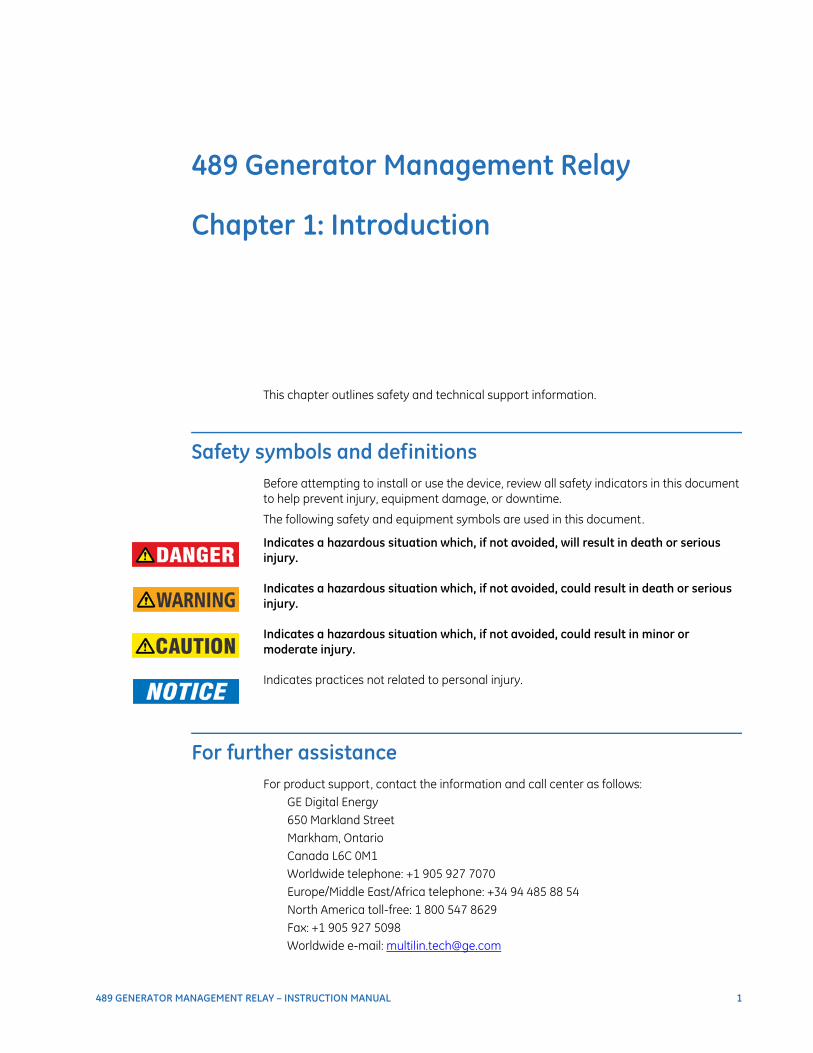
Safety symbols and definitionsBefore attempting to install or use the device, review all safety indicators in this document to help prevent injury, equipment damage, or downtime.
The following safety and equipment symbols are used in this document.
Indicates a hazardous situation which, if not avoided, will result in death or serious injury.
Indicates a hazardous situation which, if not avoided, could result in death or serious injury.
Indicates a hazardous situation which, if not avoided, could result in minor or moderate injury.
Indicates practices not related to personal injury.
For further assistanceFor product support, contact the information and call center as follows:
GE Digital Energy650 Markland StreetMarkham, OntarioCanada L6C 0M1Worldwide telephone: +1 905 927 7070Europe/Middle East/Africa telephone: +34 94 485 88 54North America toll-free: 1 800 547 8629Fax: +1 905 927 5098Worldwide e-mail: [email protected]

2 489 GENERATOR MANAGEMENT RELAY – INSTRUCTION MANUAL
FOR FURTHER ASSISTANCE CHAPTER 1: INTRODUCTION
Europe e-mail: [email protected]: http://www.gedigitalenergy.com/multilin
489 GENERATOR MANAGEMENT RELAY – INSTRUCTION MANUAL 3
489 Generator Management Relay
Chapter 2: Getting Started
Getting Started
Important Procedures
Cautions and WarningsPlease read this chapter to guide you through the initial setup of your new relay.
Before attempting to install or use the relay, it is imperative that all WARNINGS and CAUTIONS in this manual are reviewed to help prevent personal injury, equipment damage, and/or downtime.
Inspection Checklist• Open the relay packaging and inspect the unit for physical damage.
• View the rear nameplate and verify that the correct model has been ordered.
• Ensure that the following items are included:
• Instruction Manual
• GE EnerVista CD (includes software and relay documentation)
• mounting screws
• For product information, instruction manual updates, and the latest software updates, please visit the GE Multilin website at http://www.gedigitalenergy.com.
If there is any noticeable physical damage, or any of the contents listed are missing, please contact GE Multilin immediately.

4 489 GENERATOR MANAGEMENT RELAY – INSTRUCTION MANUAL
IMPORTANT PROCEDURES CHAPTER 2: GETTING STARTED
Manual OrganizationReading a lengthy instruction manual on a new product is not a task most people enjoy. To speed things up, this introductory chapter provides guidelines for basic relay usability. Important wiring considerations and precautions discussed in Electrical Installation on page 45 should be observed for reliable operation. Detailed information regarding accuracy, output relay contact ratings, and so forth are detailed in Specifications on page 24. The remainder of this manual should be read and kept for reference to ensure maximum benefit from the 489 Generator Management Relay. For further information, please consult your local sales representative or the factory. Comments about new features or modifications for your specific requirements are welcome and encouraged.
Setpoints and actual values are indicated as follows in the manual:
A4 MAINTENANCE TRIP COUNTERS TOTAL NUMBER OF TRIPS
This ‘path representation’ illustrates the location of an specific actual value or setpoint with regards to its previous menus and sub-menus. In the example above, the TOTAL NUMBER
OF TRIPS actual value is shown to be an item in the TRIP COUNTERS sub-menu, which itself is an item in the A4 MAINTENANCE menu, which is an item of ACTUAL VALUES.
Sub-menu levels are entered by pressing the MESSAGE or ENTER key. When inside a submenu, the MESSAGE or ESCAPE key returns to the previous sub-menu. The MESSAGE and MESSAGE keys are used to scroll through the settings in a sub-menu. The display indicates which keys can be used at any given point.

CHAPTER 2: GETTING STARTED USING THE RELAY
489 GENERATOR MANAGEMENT RELAY – INSTRUCTION MANUAL 5
Using the Relay
Menu NavigationThe relay has three types of display messages: actual value, setpoint, and target messages. A summary of the menu structure for setpoints and actual values can be found at the beginning of chapters 5 and 6, respectively.
Setpoints are programmable settings entered by the user. These types of messages are located within a menu structure that groups the information into categories. Navigating the menu structure is described below.
Actual values include the following information:
1. Generator and System Status:
a. Generator status either online, offline, or tripped.
b. The status of digital inputs.
c. Last trip information, including values such as cause of last trip, time and date oftrip, pre-trip temperature measurements, pre-trip analog inputs values, and pre-trip instantaneous values of power system quantities.
d. Active alarms.
e. Relay date and time.
2. Metering Data:
a. Instantaneous current measurements including phase, neutral, and ground cur-
rents.
b. Instantaneous phase to phase and phase to ground voltages (depending on theVT connections), average voltage, and system frequency.
c. Power quantities including apparent, real and reactive power.
d. Current and power demand including peak values.
e. Analog inputs.
f. Generator speed.
g. System phasors.
h. RTD temperatures.
3. Learned Data:
a. Average magnitudes of generator load, negative-sequence current, and phase-
phase voltage.
b. RTD learned data, which includes the maximum temperature measured by eachof the twelve (12) RTDs.
c. Minimum and maximum values of analog inputs.
4. Maintenance data. This is useful statistical information that may be used for preventive maintenance. It includes:
a. Trip counters
6 489 GENERATOR MANAGEMENT RELAY – INSTRUCTION MANUAL
USING THE RELAY CHAPTER 2: GETTING STARTED
b. General counters such as number of breaker operations and number of thermalresets.
c. Generator hours online timer.
5. Event recorder downloading tool.
6. Product information including model number, firmware version, additional product information, and calibration dates.
7. Oscillography and data logger downloading tool.
Alarm, trip conditions, diagnostics, and system flash messages are grouped under Target Messages.
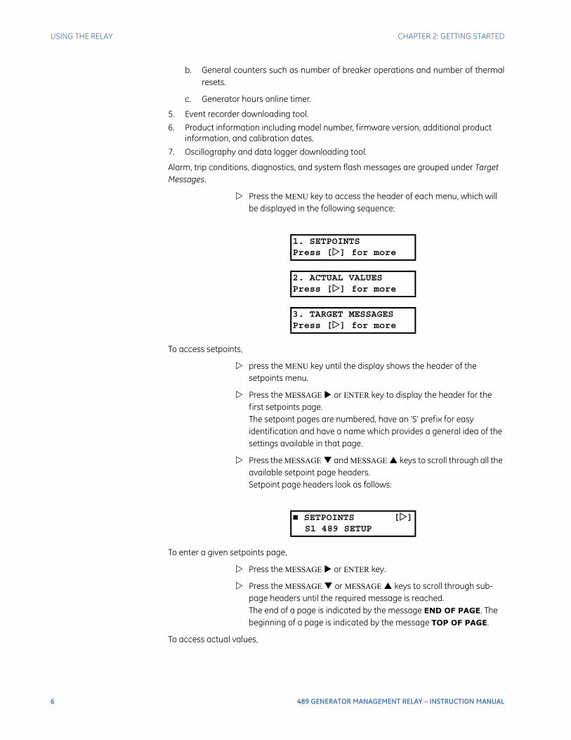
Press the MENU key to access the header of each menu, which will be displayed in the following sequence:
To access setpoints,
press the MENU key until the display shows the header of the setpoints menu.
Press the MESSAGE or ENTER key to display the header for the first setpoints page. The setpoint pages are numbered, have an ‘S’ prefix for easy identification and have a name which provides a general idea of the settings available in that page.
Press the MESSAGE and MESSAGE keys to scroll through all the available setpoint page headers. Setpoint page headers look as follows:
To enter a given setpoints page,
Press the MESSAGE or ENTER key.
Press the MESSAGE or MESSAGE keys to scroll through sub-page headers until the required message is reached. The end of a page is indicated by the message END OF PAGE. The beginning of a page is indicated by the message TOP OF PAGE.
To access actual values,
1. SETPOINTSPress [] for more
2. ACTUAL VALUESPress [] for more
3. TARGET MESSAGESPress [] for more
SETPOINTS []S1 489 SETUP
CHAPTER 2: GETTING STARTED USING THE RELAY
489 GENERATOR MANAGEMENT RELAY – INSTRUCTION MANUAL 7
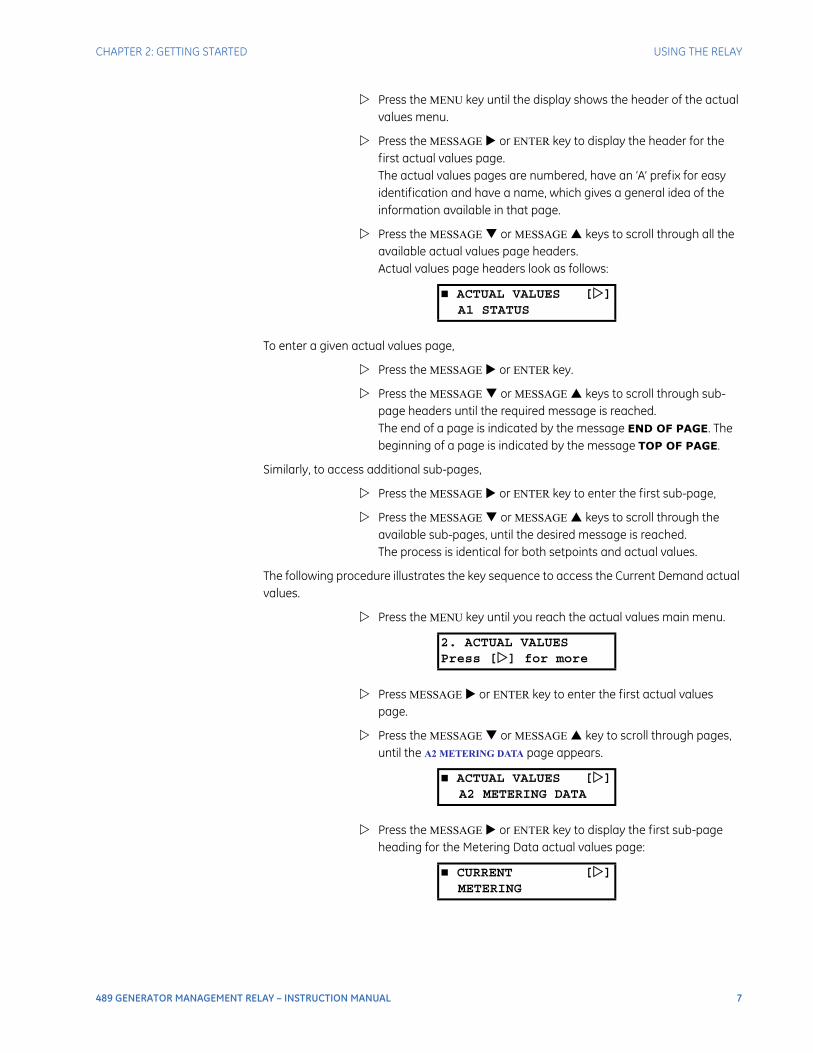
Press the MENU key until the display shows the header of the actual values menu.
Press the MESSAGE or ENTER key to display the header for the first actual values page. The actual values pages are numbered, have an ‘A’ prefix for easy identification and have a name, which gives a general idea of the information available in that page.
Press the MESSAGE or MESSAGE keys to scroll through all the available actual values page headers. Actual values page headers look as follows:
To enter a given actual values page,
Press the MESSAGE or ENTER key.
Press the MESSAGE or MESSAGE keys to scroll through sub-page headers until the required message is reached. The end of a page is indicated by the message END OF PAGE. The beginning of a page is indicated by the message TOP OF PAGE.
Similarly, to access additional sub-pages,
Press the MESSAGE or ENTER key to enter the first sub-page,
Press the MESSAGE or MESSAGE keys to scroll through the available sub-pages, until the desired message is reached. The process is identical for both setpoints and actual values.
The following procedure illustrates the key sequence to access the Current Demand actual values.
Press the MENU key until you reach the actual values main menu.
Press MESSAGE or ENTER key to enter the first actual values page.
Press the MESSAGE or MESSAGE key to scroll through pages, until the A2 METERING DATA page appears.
Press the MESSAGE or ENTER key to display the first sub-page heading for the Metering Data actual values page:
ACTUAL VALUES []A1 STATUS
2. ACTUAL VALUESPress [] for more
ACTUAL VALUES []A2 METERING DATA
CURRENT []METERING
8 489 GENERATOR MANAGEMENT RELAY – INSTRUCTION MANUAL
USING THE RELAY CHAPTER 2: GETTING STARTED
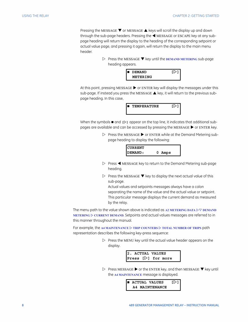
Pressing the MESSAGE or MESSAGE keys will scroll the display up and down through the sub-page headers. Pressing the MESSAGE or ESCAPE key at any sub-page heading will return the display to the heading of the corresponding setpoint or actual value page, and pressing it again, will return the display to the main menu header.
Press the MESSAGE key until the DEMAND METERING sub-page heading appears.
At this point, pressing MESSAGE or ENTER key will display the messages under this sub-page. If instead you press the MESSAGE key, it will return to the previous sub-page heading. In this case,
When the symbols and [] appear on the top line, it indicates that additional sub-pages are available and can be accessed by pressing the MESSAGE or ENTER key.
Press the MESSAGE or ENTER while at the Demand Metering sub-page heading to display the following:
Press MESSAGE key to return to the Demand Metering sub-page heading.
Press the MESSAGE key to display the next actual value of this sub-page. Actual values and setpoints messages always have a colon separating the name of the value and the actual value or setpoint. This particular message displays the current demand as measured by the relay.
The menu path to the value shown above is indicated as A2 METERING DATA DEMAND
METERING CURRENT DEMAND. Setpoints and actual values messages are referred to in this manner throughout the manual.
For example, the A4 MAINTENANCE TRIP COUNTERS TOTAL NUMBER OF TRIPS path representation describes the following key-press sequence:
Press the MENU key until the actual value header appears on the display.
Press MESSAGE or the ENTER key, and then MESSAGE key until the A4 MAINTENANCE message is displayed.
DEMAND []METERING
TEMPERATURE []
CURRENTDEMAND: 0 Amps
2. ACTUAL VALUESPress [] for more
ACTUAL VALUES []A4 MAINTENANCE
CHAPTER 2: GETTING STARTED USING THE RELAY
489 GENERATOR MANAGEMENT RELAY – INSTRUCTION MANUAL 9
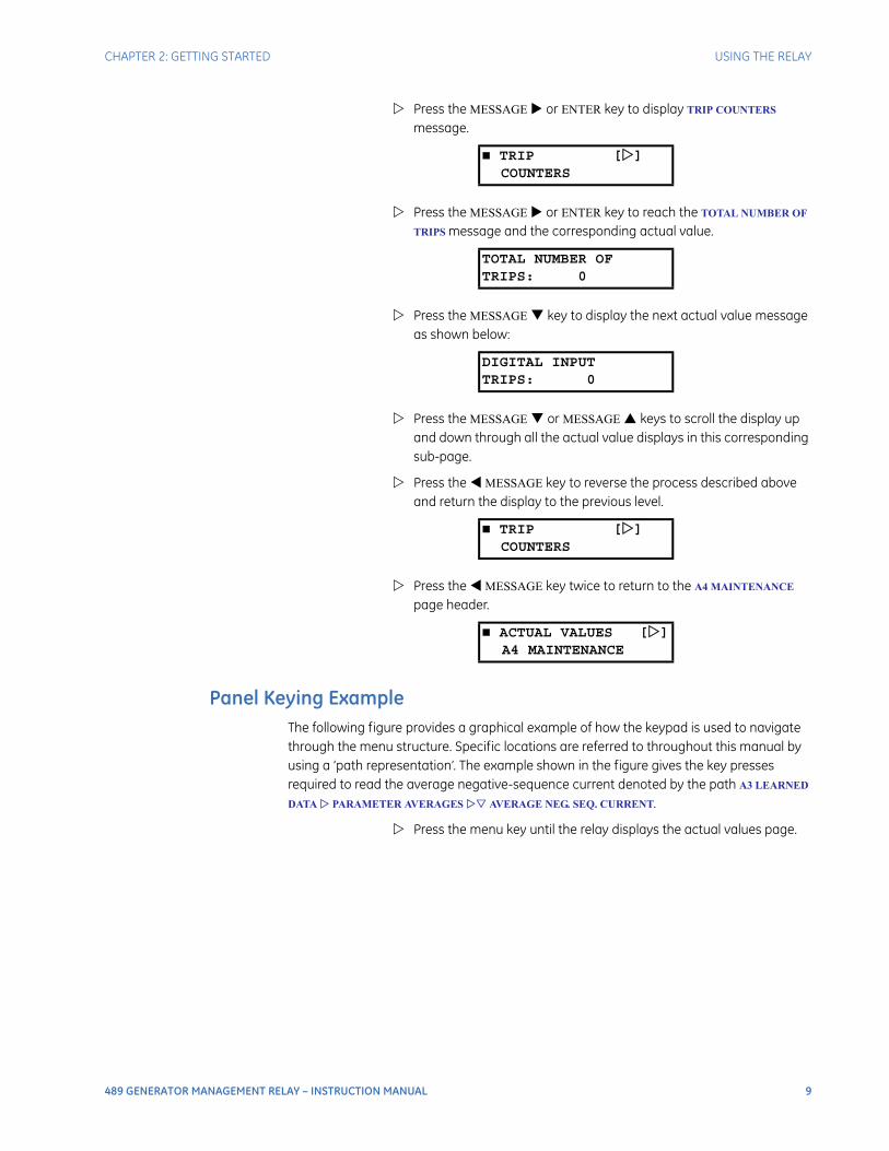
Press the MESSAGE or ENTER key to display TRIP COUNTERS message.
Press the MESSAGE or ENTER key to reach the TOTAL NUMBER OF
TRIPS message and the corresponding actual value.
Press the MESSAGE key to display the next actual value message as shown below:
Press the MESSAGE or MESSAGE keys to scroll the display up and down through all the actual value displays in this corresponding sub-page.
Press the MESSAGE key to reverse the process described above and return the display to the previous level.
Press the MESSAGE key twice to return to the A4 MAINTENANCE page header.
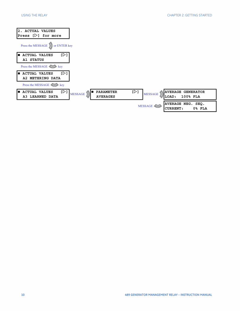
Panel Keying ExampleThe following figure provides a graphical example of how the keypad is used to navigate through the menu structure. Specific locations are referred to throughout this manual by using a ‘path representation’. The example shown in the figure gives the key presses required to read the average negative-sequence current denoted by the path A3 LEARNED
DATA PARAMETER AVERAGES AVERAGE NEG. SEQ. CURRENT.
Press the menu key until the relay displays the actual values page.
TRIP []COUNTERS
TOTAL NUMBER OFTRIPS: 0
DIGITAL INPUTTRIPS: 0
TRIP []COUNTERS
ACTUAL VALUES []A4 MAINTENANCE
10 489 GENERATOR MANAGEMENT RELAY – INSTRUCTION MANUAL
USING THE RELAY CHAPTER 2: GETTING STARTED
2. ACTUAL VALUESPress [] for more
Press the MESSAGE or ENTER key
ACTUAL VALUES []A1 STATUS
Press the MESSAGE key
ACTUAL VALUES []A2 METERING DATA
Press the MESSAGE key
ACTUAL VALUES []A3 LEARNED DATA
MESSAGE PARAMETER []
AVERAGESMESSAGE
AVERAGE GENERATORLOAD: 100% FLA
MESSAGE AVERAGE NEG. SEQ.CURRENT: 0% FLA

CHAPTER 2: GETTING STARTED CHANGING SETPOINTS
489 GENERATOR MANAGEMENT RELAY – INSTRUCTION MANUAL 11
Changing Setpoints
IntroductionThere are several classes of setpoints, each distinguished by the way their values are displayed and edited.
The relay's menu is arranged in a tree structure. Each setting in the menu is referred to as a setpoint, and each setpoint in the menu may be accessed as described in the previous section.
The settings are arranged in pages with each page containing related settings; for example, all the Phase Overcurrent settings are contained within the same page. As previously explained, the top menu page of each setting group describes the settings contained within that page. Pressing the MESSAGE keys allows the user to move between these top menus.
All of the 489 settings fall into one of following categories: device settings, system settings, digital input settings, output relay settings, current element settings, voltage element settings, power element settings, RTD temperature settings, thermal model settings, monitoring settings, analog input/output settings, and testing settings.
IMPORTANT NOTE: Settings are stored and used by the relay immediately after they are entered. As such, caution must be exercised when entering settings while the relay is in service. Modifying or storing protection settings is not recommended when the relay is in service since any incompatibility or lack of coordination with other previously saved settings may cause unwanted operations.
Now that we have become more familiar with maneuvering through messages, we can learn how to edit the values used by all setpoint classes.
Hardware and passcode security features are designed to provide protection against unauthorized setpoint changes. Since we will be programming new setpoints using the front panel keys, a hardware jumper must be installed across the setpoint access terminals (C1 and C2) on the back of the relay case. Attempts to enter a new setpoint without this electrical connection will result in an error message.
The jumper does not restrict setpoint access via serial communications. The relay has a programmable passcode setpoint, which may be used to disallow setpoint changes from both the front panel and the serial communications ports. This passcode consists of up to eight (8) alphanumeric characters.
The factory default passcode is “0”. When this specific value is programmed into the relay it has the effect of removing all setpoint modification restrictions. Therefore, only the setpoint access jumper can be used to restrict setpoint access via the front panel and there are no restrictions via the communications ports.
When the passcode is programmed to any other value, setpoint access is restricted for the front panel and all communications ports. Access is not permitted until the passcode is entered via the keypad or is programmed into a specific register (via communications). Note that enabling setpoint access on one interface does not automatically enable access for any of the other interfaces (i.e., the passcode must be explicitly set in the relay via the interface from which access is desired).
12 489 GENERATOR MANAGEMENT RELAY – INSTRUCTION MANUAL
CHANGING SETPOINTS CHAPTER 2: GETTING STARTED
A front panel command can disable setpoint access once all modifications are complete. For the communications ports, writing an invalid passcode into the register previously used to enable setpoint access disables access. In addition, setpoint access is automatically disabled on an interface if no activity is detected for thirty minutes.
The EnerVista 489 Setup software incorporates a facility for programming the relay passcode as well as enabling and disabling setpoint access. For example, when an attempt is made to modify a setpoint but access is restricted, the software will prompt the user to enter the passcode and send it to the relay before the setpoint is actually written to the relay. If a SCADA system is used for relay programming, it is the programmer's responsibility to incorporate appropriate security for the application.
The HELP KeyPressing the HELP key displays context-sensitive information about setpoints such as the range of values and the method of changing the setpoint. Help messages will automatically scroll through all messages currently appropriate.
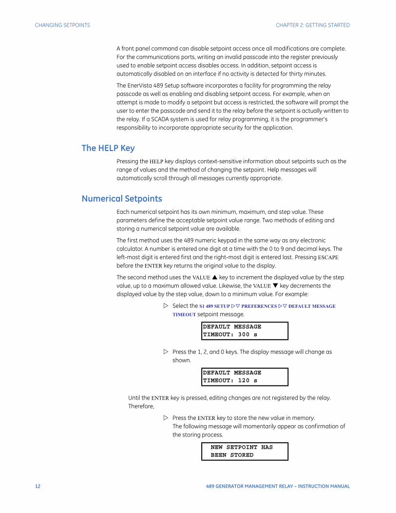
Numerical SetpointsEach numerical setpoint has its own minimum, maximum, and step value. These parameters define the acceptable setpoint value range. Two methods of editing and storing a numerical setpoint value are available.
The first method uses the 489 numeric keypad in the same way as any electronic calculator. A number is entered one digit at a time with the 0 to 9 and decimal keys. The left-most digit is entered first and the right-most digit is entered last. Pressing ESCAPE before the ENTER key returns the original value to the display.
The second method uses the VALUE key to increment the displayed value by the step value, up to a maximum allowed value. Likewise, the VALUE key decrements the displayed value by the step value, down to a minimum value. For example:
Select the S1 489 SETUP PREFERENCES DEFAULT MESSAGE
TIMEOUT setpoint message.
Press the 1, 2, and 0 keys. The display message will change as shown.
Until the ENTER key is pressed, editing changes are not registered by the relay. Therefore,
Press the ENTER key to store the new value in memory. The following message will momentarily appear as confirmation of the storing process.
DEFAULT MESSAGETIMEOUT: 300 s
DEFAULT MESSAGETIMEOUT: 120 s
NEW SETPOINT HASBEEN STORED
CHAPTER 2: GETTING STARTED CHANGING SETPOINTS
489 GENERATOR MANAGEMENT RELAY – INSTRUCTION MANUAL 13
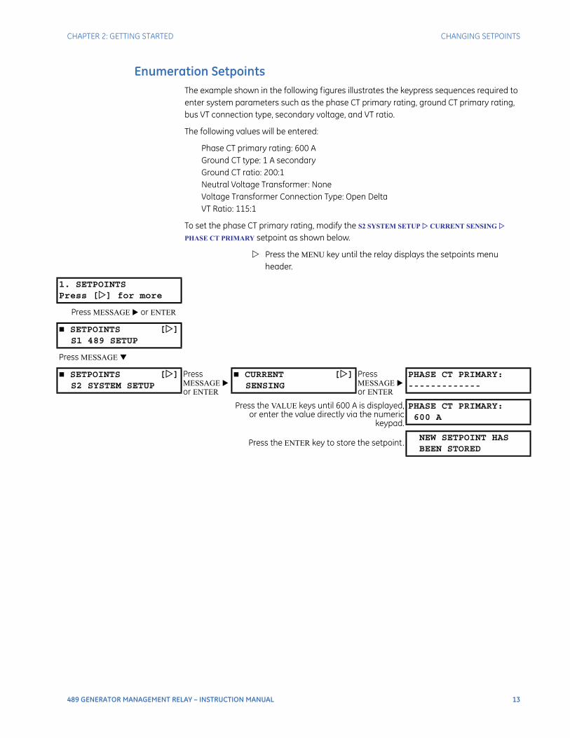
Enumeration SetpointsThe example shown in the following figures illustrates the keypress sequences required to enter system parameters such as the phase CT primary rating, ground CT primary rating, bus VT connection type, secondary voltage, and VT ratio.
The following values will be entered:
Phase CT primary rating: 600 AGround CT type: 1 A secondaryGround CT ratio: 200:1Neutral Voltage Transformer: NoneVoltage Transformer Connection Type: Open DeltaVT Ratio: 115:1
To set the phase CT primary rating, modify the S2 SYSTEM SETUP CURRENT SENSING
PHASE CT PRIMARY setpoint as shown below.
Press the MENU key until the relay displays the setpoints menu header.
1. SETPOINTSPress [] for more
Press MESSAGE or ENTER
SETPOINTS []S1 489 SETUP
Press MESSAGE
SETPOINTS []S2 SYSTEM SETUP
Press MESSAGE or ENTER
CURRENT []SENSING
Press MESSAGE or ENTER
PHASE CT PRIMARY:-------------
Press the VALUE keys until 600 A is displayed,or enter the value directly via the numeric
keypad.
PHASE CT PRIMARY:600 A
Press the ENTER key to store the setpoint.NEW SETPOINT HASBEEN STORED
14 489 GENERATOR MANAGEMENT RELAY – INSTRUCTION MANUAL
CHANGING SETPOINTS CHAPTER 2: GETTING STARTED
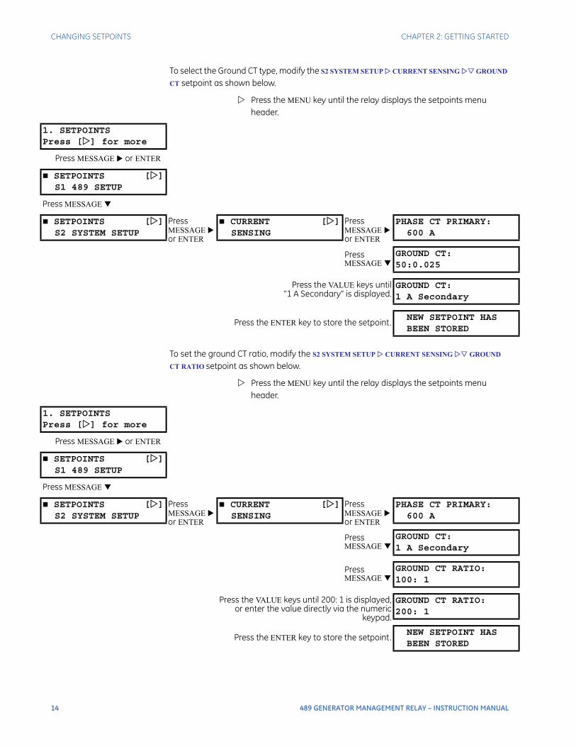
To select the Ground CT type, modify the S2 SYSTEM SETUP CURRENT SENSING GROUND
CT setpoint as shown below.
Press the MENU key until the relay displays the setpoints menu header.
To set the ground CT ratio, modify the S2 SYSTEM SETUP CURRENT SENSING GROUND
CT RATIO setpoint as shown below.
Press the MENU key until the relay displays the setpoints menu header.
1. SETPOINTSPress [] for more
Press MESSAGE or ENTER
SETPOINTS []S1 489 SETUP
Press MESSAGE
SETPOINTS []S2 SYSTEM SETUP
Press MESSAGE or ENTER
CURRENT []SENSING
Press MESSAGE or ENTER
PHASE CT PRIMARY:600 A
Press MESSAGE
GROUND CT:50:0.025
Press the VALUE keys until“1 A Secondary” is displayed.
GROUND CT:1 A Secondary
Press the ENTER key to store the setpoint.NEW SETPOINT HASBEEN STORED
1. SETPOINTSPress [] for more
Press MESSAGE or ENTER
SETPOINTS []S1 489 SETUP
Press MESSAGE
SETPOINTS []S2 SYSTEM SETUP
Press MESSAGE or ENTER
CURRENT []SENSING
Press MESSAGE or ENTER
PHASE CT PRIMARY:600 A
Press MESSAGE
GROUND CT:1 A Secondary
Press MESSAGE
GROUND CT RATIO:100: 1
Press the VALUE keys until 200: 1 is displayed,or enter the value directly via the numeric
keypad.
GROUND CT RATIO:200: 1
Press the ENTER key to store the setpoint.NEW SETPOINT HASBEEN STORED

CHAPTER 2: GETTING STARTED CHANGING SETPOINTS
489 GENERATOR MANAGEMENT RELAY – INSTRUCTION MANUAL 15
To set the VT connection type and ratings, modify the S2 SYSTEM SETUP VOLTAGE
SENSING VT CONNECTION TYPE and the S2 SYSTEM SETUP VOLTAGE SENSING
VOLTAGE TRANSFORMER RATIO setpoints as shown below.
Press the MENU key until the relay displays the setpoints menu header.
If an entered setpoint value is out of range, the relay displays a message with the following format:
In this case, 1 is the minimum setpoint value, 300 is the maximum, and 0.01 is the step value. To have access to information on maximum, minimum, and step value, press the HELP key.
Output Relay SetpointsThe output relays 1 Trip and 5 Alarm can be associated to auxiliary relays 2 to 4. Each can be selected individually, or in combination, in response to customer specific requirements. These relays are initiated through the ASSIGN ALARM RELAYS or ASSIGN TRIP RELAYS setpoints specific to a protection element or function.
1. SETPOINTSPress [] for more
Press MESSAGE or ENTER
SETPOINTS []S1 489 SETUP
Press MESSAGE
SETPOINTS []S2 SYSTEM SETUP
Press MESSAGE or ENTER
CURRENT []SENSING
Press MESSAGE
VOLTAGE []SENSING
Press MESSAGE or ENTER
VT CONNECTION TYPE:None
Press the VALUE keys until“Open Delta” is displayed.
VT CONNECTION TYPE:Open Delta
Press the ENTER key to store the setpoint.NEW SETPOINT HASBEEN STORED
Press MESSAGE
VOLTAGE TRANSFORMERRATIO: 5.00: 1
Press the VALUE keys until 115.00 : 1 isdisplayed, or enter the value directly via the
numeric keypad.
VOLTAGE TRANSFORMERRATIO: 115.0: 1
Press the ENTER key to store the setpoint.NEW SETPOINT HASBEEN STORED
OUT-OF-RANGE! ENTER:1-300:1 by 0.01:1
“1-300:1” indicates the range and “0.01:1” indicates the step value
16 489 GENERATOR MANAGEMENT RELAY – INSTRUCTION MANUAL
CHANGING SETPOINTS CHAPTER 2: GETTING STARTED
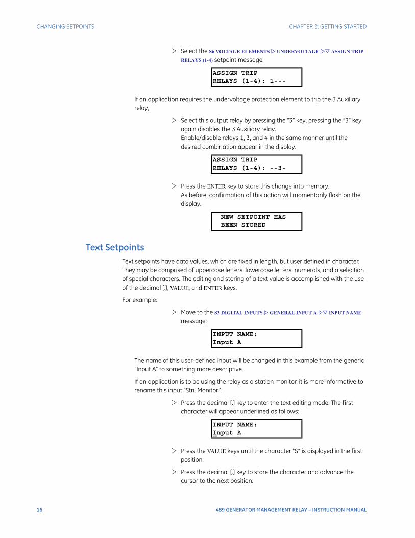
Select the S6 VOLTAGE ELEMENTS UNDERVOLTAGE ASSIGN TRIP
RELAYS (1-4) setpoint message.
If an application requires the undervoltage protection element to trip the 3 Auxiliary relay,
Select this output relay by pressing the “3” key; pressing the “3” key again disables the 3 Auxiliary relay. Enable/disable relays 1, 3, and 4 in the same manner until the desired combination appear in the display.
Press the ENTER key to store this change into memory. As before, confirmation of this action will momentarily flash on the display.
Text SetpointsText setpoints have data values, which are fixed in length, but user defined in character. They may be comprised of uppercase letters, lowercase letters, numerals, and a selection of special characters. The editing and storing of a text value is accomplished with the use of the decimal [.], VALUE, and ENTER keys.
For example:
Move to the S3 DIGITAL INPUTS GENERAL INPUT A INPUT NAME message:
The name of this user-defined input will be changed in this example from the generic “Input A” to something more descriptive.
If an application is to be using the relay as a station monitor, it is more informative to rename this input “Stn. Monitor”.
Press the decimal [.] key to enter the text editing mode. The first character will appear underlined as follows:
Press the VALUE keys until the character “S” is displayed in the first position.
Press the decimal [.] key to store the character and advance the cursor to the next position.
ASSIGN TRIPRELAYS (1-4): 1---
ASSIGN TRIPRELAYS (1-4): --3-
NEW SETPOINT HASBEEN STORED
INPUT NAME:Input A
INPUT NAME:Input A

CHAPTER 2: GETTING STARTED CHANGING SETPOINTS
489 GENERATOR MANAGEMENT RELAY – INSTRUCTION MANUAL 17
Change the second character to a “t” in the same manner.
Continue entering characters in this way until all characters of the text “Stn. Monitor” are entered. Note that a space is selected like a character. If a character is entered incorrectly, press the decimal [.] key repeatedly until the cursor returns to the position of the error. Re-enter the character as required.
Once complete, press the ENTER key to remove the solid cursor and view the result. Once a character is entered, by pressing the ENTER key, it is automatically saved in flash memory, as a new setpoint.
INPUT NAME:Stn. Monitor

18 489 GENERATOR MANAGEMENT RELAY – INSTRUCTION MANUAL
INSTALLATION CHAPTER 2: GETTING STARTED
Installation
Placing the Relay in ServiceThe relay is defaulted to the Not Ready state when it leaves the factory. A minor self-test warning message informs the user that the 489 Generator Management Relay has not yet been programmed. If this warning is ignored, protection will be active using factory default setpoints and the Relay In Service LED Indicator will be on.
TestingExtensive commissioning tests are available in Chapter 7. Tables for recording required settings are available in Microsoft Excel format from the GE Multilin website at http://www.GEmultilin.com. The website also contains additional technical papers and FAQs relevant to the 489 Generator Management Relay.
489 GENERATOR MANAGEMENT RELAY – INSTRUCTION MANUAL 19
489 Generator Management Relay
Chapter 3: Introduction
Introduction
Overview
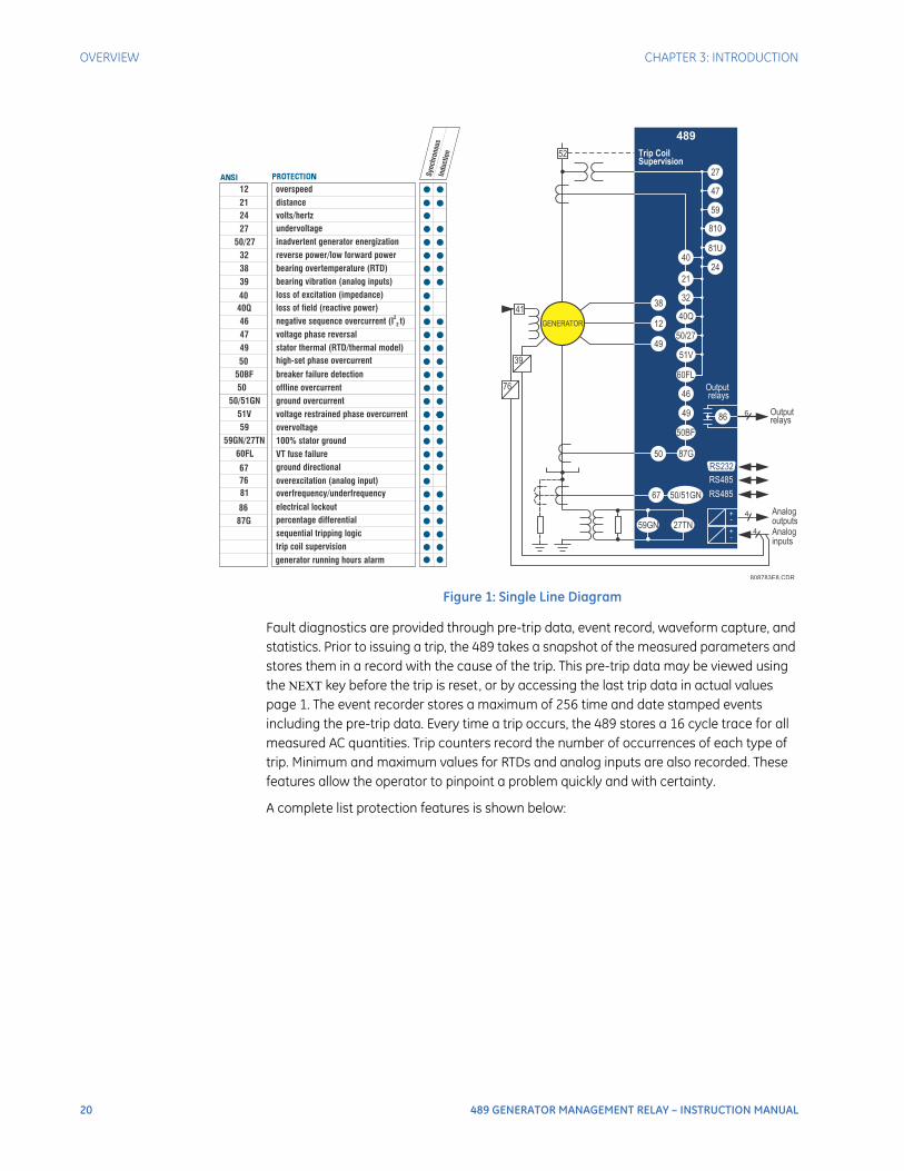
DescriptionThe 489 Generator Management Relay is a microprocessor-based relay designed for the protection and management of synchronous and induction generators. The 489 is equipped with 6 output relays for trips and alarms. Generator protection, fault diagnostics, power metering, and RTU functions are integrated into one economical drawout package. The single line diagram illustrates the 489 functionality using ANSI (American National Standards Institute) device numbers.
20 489 GENERATOR MANAGEMENT RELAY – INSTRUCTION MANUAL
OVERVIEW CHAPTER 3: INTRODUCTION
Figure 1: Single Line Diagram
Fault diagnostics are provided through pre-trip data, event record, waveform capture, and statistics. Prior to issuing a trip, the 489 takes a snapshot of the measured parameters and stores them in a record with the cause of the trip. This pre-trip data may be viewed using the NEXT key before the trip is reset, or by accessing the last trip data in actual values page 1. The event recorder stores a maximum of 256 time and date stamped events including the pre-trip data. Every time a trip occurs, the 489 stores a 16 cycle trace for all measured AC quantities. Trip counters record the number of occurrences of each type of trip. Minimum and maximum values for RTDs and analog inputs are also recorded. These features allow the operator to pinpoint a problem quickly and with certainty.
A complete list protection features is shown below:
87G
27TN59GN
49
50
46
86
49
12
38
50BF
Outputrelays
Trip CoilSupervision
RS485
RS485
Analoginputs
Analogoutputs
Outputrelays
489
RS232
+
+
-
-
4
4
6
52
GENERATOR
41
39
76
50/51GN
60FL
51V
50/27
32
21
40
40Q
24
59
810
81U
27
47
67
12 overspeed
volts/hertzundervoltageinadvertent generator energizationreverse power/low forward powerbearing overtemperature (RTD)bearing vibration (analog inputs)
loss of field (reactive power)negative sequence overcurrent (I t)2
2
voltage phase reversalstator thermal (RTD/thermal model)
breaker failure detectionoffline overcurrentground overcurrentvoltage restrained phase overcurrentovervoltage100% stator groundVT fuse failure
overexcitation (analog input)overfrequency/underfrequency
percentage differentialelectrical lockout
ground directional
high-set phase overcurrent
loss of excitation (impedance)
distance
sequential tripping logictrip coil supervision
2427
50/27323839
40Q464749
50BF50
50/51GN51V59
59GN/27TN60FL
7681
87G86
67
50
40
21
Sync
hron
ous
Indu
ctio
n
generator running hours alarm
808783E8.CDR
CHAPTER 3: INTRODUCTION OVERVIEW
489 GENERATOR MANAGEMENT RELAY – INSTRUCTION MANUAL 21
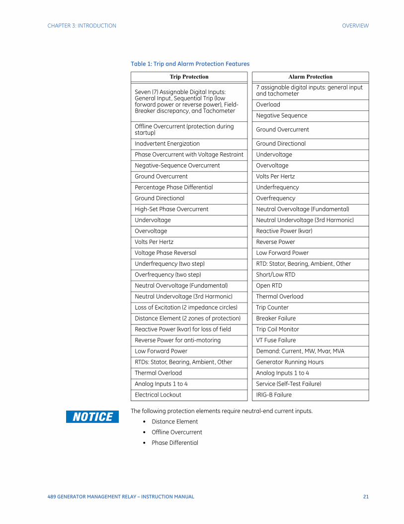
The following protection elements require neutral-end current inputs.
• Distance Element
• Offline Overcurrent
• Phase Differential
Table 1: Trip and Alarm Protection Features
Trip Protection Alarm Protection
Seven (7) Assignable Digital Inputs: General Input, Sequential Trip (low forward power or reverse power), Field-Breaker discrepancy, and Tachometer
7 assignable digital inputs: general input and tachometer
Overload
Negative Sequence
Offline Overcurrent (protection during startup) Ground Overcurrent
Inadvertent Energization Ground Directional
Phase Overcurrent with Voltage Restraint Undervoltage
Negative-Sequence Overcurrent Overvoltage
Ground Overcurrent Volts Per Hertz
Percentage Phase Differential Underfrequency
Ground Directional Overfrequency
High-Set Phase Overcurrent Neutral Overvoltage (Fundamental)
Undervoltage Neutral Undervoltage (3rd Harmonic)
Overvoltage Reactive Power (kvar)
Volts Per Hertz Reverse Power
Voltage Phase Reversal Low Forward Power
Underfrequency (two step) RTD: Stator, Bearing, Ambient, Other
Overfrequency (two step) Short/Low RTD
Neutral Overvoltage (Fundamental) Open RTD
Neutral Undervoltage (3rd Harmonic) Thermal Overload
Loss of Excitation (2 impedance circles) Trip Counter
Distance Element (2 zones of protection) Breaker Failure
Reactive Power (kvar) for loss of field Trip Coil Monitor
Reverse Power for anti-motoring VT Fuse Failure
Low Forward Power Demand: Current, MW, Mvar, MVA
RTDs: Stator, Bearing, Ambient, Other Generator Running Hours
Thermal Overload Analog Inputs 1 to 4
Analog Inputs 1 to 4 Service (Self-Test Failure)
Electrical Lockout IRIG-B Failure

22 489 GENERATOR MANAGEMENT RELAY – INSTRUCTION MANUAL
OVERVIEW CHAPTER 3: INTRODUCTION
Power metering is a standard feature in the 489. The table below outlines the metered parameters available to the operator through the front panel and communications ports. The 489 is equipped with three independent communications ports. The front panel RS232 port may be used for setpoint programming, local interrogation or control, and firmware upgrades. The computer RS485 port may be connected to a PLC, DCS, or PC based interface software. The auxiliary RS485 port may be used for redundancy or simultaneous interrogation and/or control from a second PLC, DCS, or PC program. There are also four 4 to 20 mA transducer outputs that may be assigned to any measured parameter. The range of these outputs is scalable. Additional features are outlined below.
OrderingAll features of the 489 are standard, there are no options. The phase CT secondaries, control power, and analog output range must be specified at the time of order. There are two ground CT inputs: one for a 50:0.025 CT and one for a ground CT with a 1 A secondary (may also accommodate a 5 A secondary). The VT inputs accommodate VTs in either a delta or wye configuration. The output relays are always non-failsafe with the exception of the service relay. The EnerVista 489 Setup software is provided with each unit. A metal demo case may be ordered for demonstration or testing purposes.
Table 2: Metering and Additional Features
Metering Additional Features
Voltage (phasors) Drawout Case (maintenance and testing)
Current (phasors) and Amps Demand Breaker Failure
Real Power, MW Demand, MWh Trip Coil Supervision
Apparent Power and MVA demand VT Fuse Failure
MW, Mvar, and ±MVarh demand Simulation
Frequency Flash Memory for easy firmware upgrades
Power Factor
RTD
Speed in RPM with a Key Phasor Input
User-Programmable Analog Inputs
CHAPTER 3: INTRODUCTION OVERVIEW
489 GENERATOR MANAGEMENT RELAY – INSTRUCTION MANUAL 23
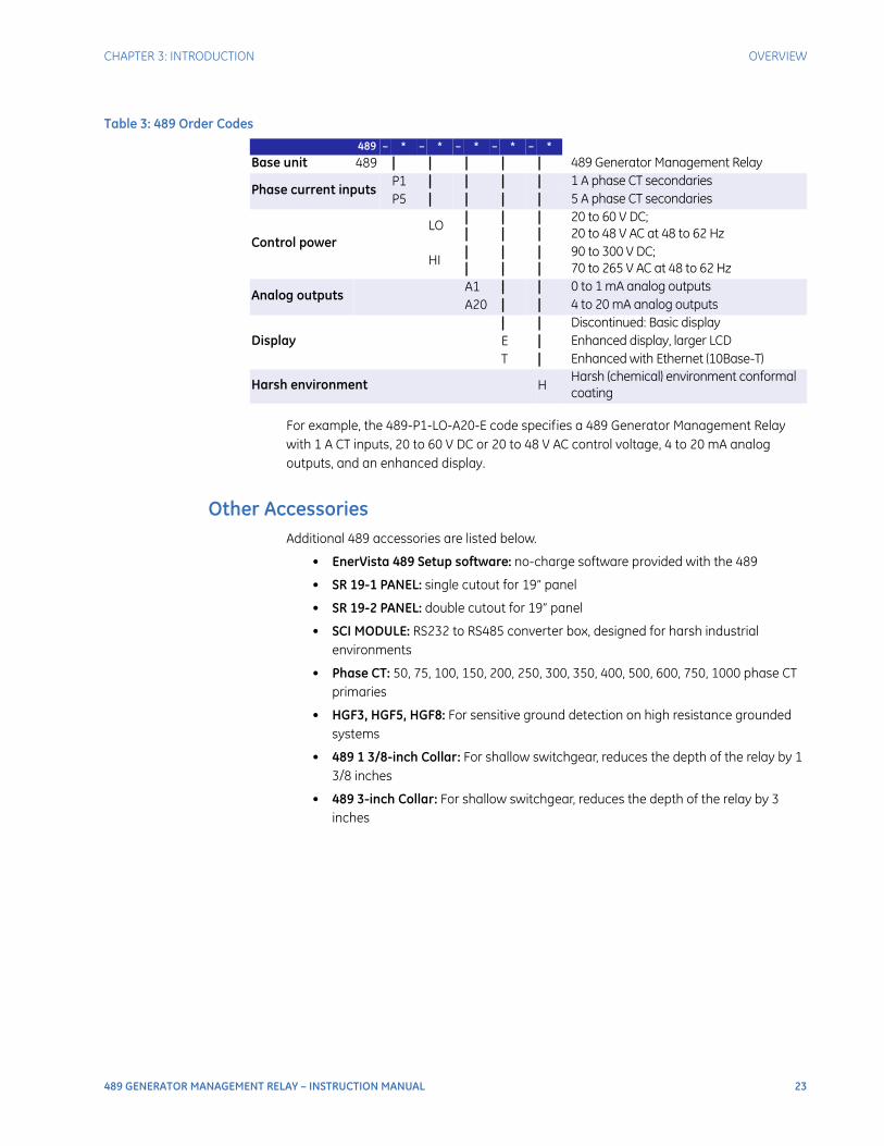
For example, the 489-P1-LO-A20-E code specifies a 489 Generator Management Relay with 1 A CT inputs, 20 to 60 V DC or 20 to 48 V AC control voltage, 4 to 20 mA analog outputs, and an enhanced display.
Other AccessoriesAdditional 489 accessories are listed below.
• EnerVista 489 Setup software: no-charge software provided with the 489
• SR 19-1 PANEL: single cutout for 19” panel
• SR 19-2 PANEL: double cutout for 19” panel
• SCI MODULE: RS232 to RS485 converter box, designed for harsh industrial environments
• Phase CT: 50, 75, 100, 150, 200, 250, 300, 350, 400, 500, 600, 750, 1000 phase CT primaries
• HGF3, HGF5, HGF8: For sensitive ground detection on high resistance grounded systems
• 489 1 3/8-inch Collar: For shallow switchgear, reduces the depth of the relay by 1 3/8 inches
• 489 3-inch Collar: For shallow switchgear, reduces the depth of the relay by 3 inches
Table 3: 489 Order Codes
489 – * – * – * – * – *
Base unit 489 | | | | | 489 Generator Management Relay
Phase current inputsP1 | | | | 1 A phase CT secondariesP5 | | | | 5 A phase CT secondaries
Control powerLO
||
||
||
20 to 60 V DC;20 to 48 V AC at 48 to 62 Hz
HI||
||
||
90 to 300 V DC;70 to 265 V AC at 48 to 62 Hz
Analog outputsA1 | | 0 to 1 mA analog outputsA20 | | 4 to 20 mA analog outputs
Display| | Discontinued: Basic displayE | Enhanced display, larger LCDT | Enhanced with Ethernet (10Base-T)
Harsh environment HHarsh (chemical) environment conformal coating
24 489 GENERATOR MANAGEMENT RELAY – INSTRUCTION MANUAL
SPECIFICATIONS CHAPTER 3: INTRODUCTION
Specifications
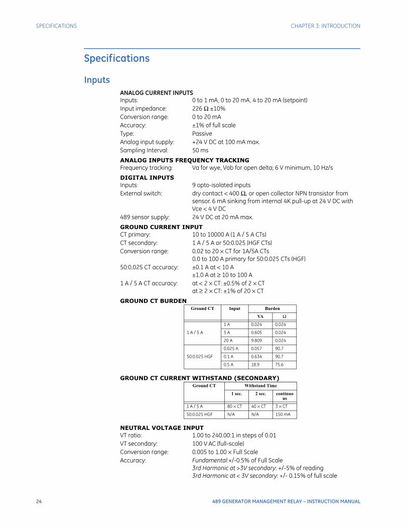
InputsANALOG CURRENT INPUTSInputs: 0 to 1 mA, 0 to 20 mA, 4 to 20 mA (setpoint)Input impedance: 226 Ω ±10%Conversion range: 0 to 20 mAAccuracy: ±1% of full scaleType: PassiveAnalog input supply: +24 V DC at 100 mA max.Sampling Interval: 50 ms
ANALOG INPUTS FREQUENCY TRACKINGFrequency tracking: Va for wye, Vab for open delta; 6 V minimum, 10 Hz/s
DIGITAL INPUTSInputs: 9 opto-isolated inputsExternal switch: dry contact < 400 Ω, or open collector NPN transistor from
sensor. 6 mA sinking from internal 4K pull-up at 24 V DC with Vce < 4 V DC
489 sensor supply: 24 V DC at 20 mA max.
GROUND CURRENT INPUTCT primary: 10 to 10000 A (1 A / 5 A CTs)CT secondary: 1 A / 5 A or 50:0.025 (HGF CTs)Conversion range: 0.02 to 20 × CT for 1A/5A CTs
0.0 to 100 A primary for 50:0.025 CTs (HGF)50:0.025 CT accuracy: ±0.1 A at < 10 A
±1.0 A at ≥ 10 to 100 A1 A / 5 A CT accuracy: at < 2 × CT: ±0.5% of 2 × CT
at ≥ 2 × CT: ±1% of 20 × CT
GROUND CT BURDEN
GROUND CT CURRENT WITHSTAND (SECONDARY)
NEUTRAL VOLTAGE INPUTVT ratio: 1.00 to 240.00:1 in steps of 0.01VT secondary: 100 V AC (full-scale) Conversion range: 0.005 to 1.00 × Full ScaleAccuracy: Fundamental:+/-0.5% of Full Scale
3rd Harmonic at >3V secondary: +/-5% of reading3rd Harmonic at < 3V secondary: +/- 0.15% of full scale
Ground CT Input Burden
VA Ω
1 A / 5 A
1 A 0.024 0.024
5 A 0.605 0.024
20 A 9.809 0.024
50:0.025 HGF
0.025 A 0.057 90.7
0.1 A 0.634 90.7
0.5 A 18.9 75.6
Ground CT Withstand Time
1 sec. 2 sec. continuous
1 A / 5 A 80 × CT 40 × CT 3 × CT
50:0.025 HGF N/A N/A 150 mA
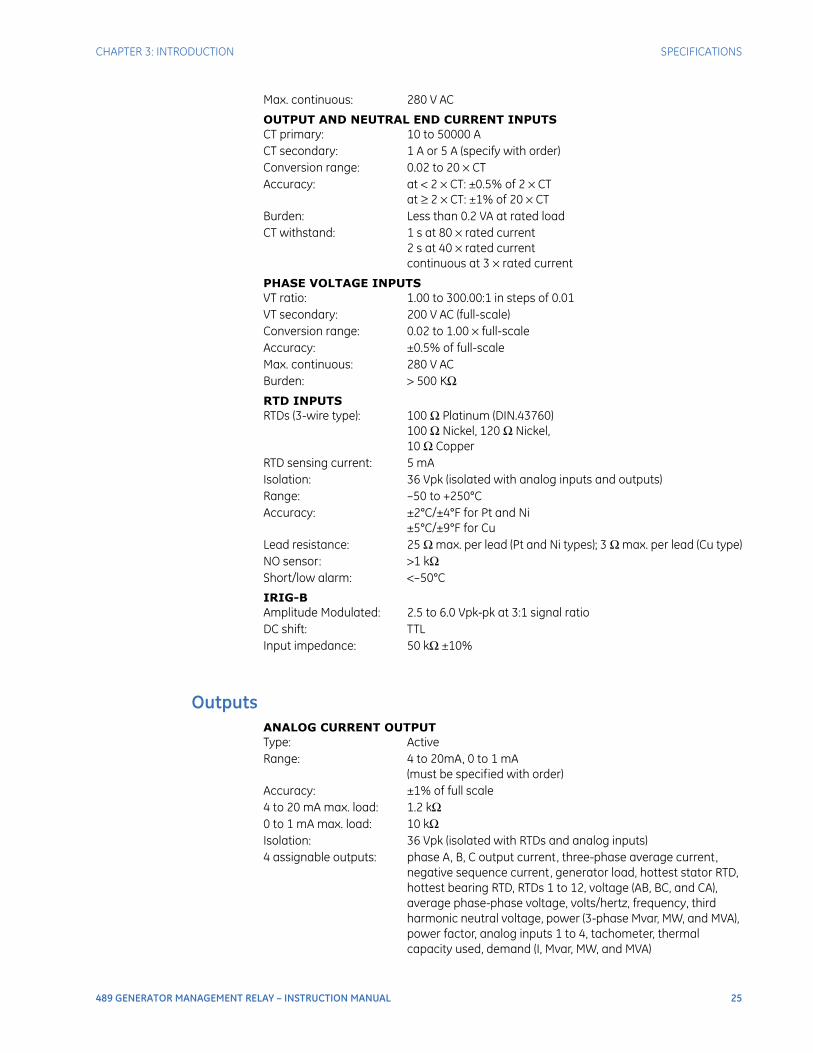
CHAPTER 3: INTRODUCTION SPECIFICATIONS
489 GENERATOR MANAGEMENT RELAY – INSTRUCTION MANUAL 25
Max. continuous: 280 V AC
OUTPUT AND NEUTRAL END CURRENT INPUTSCT primary: 10 to 50000 ACT secondary: 1 A or 5 A (specify with order)Conversion range: 0.02 to 20 × CTAccuracy: at < 2 × CT: ±0.5% of 2 × CT
at ≥ 2 × CT: ±1% of 20 × CTBurden: Less than 0.2 VA at rated load CT withstand: 1 s at 80 × rated current
2 s at 40 × rated currentcontinuous at 3 × rated current
PHASE VOLTAGE INPUTSVT ratio: 1.00 to 300.00:1 in steps of 0.01VT secondary: 200 V AC (full-scale)Conversion range: 0.02 to 1.00 × full-scaleAccuracy: ±0.5% of full-scaleMax. continuous: 280 V ACBurden: > 500 KΩRTD INPUTSRTDs (3-wire type): 100 Ω Platinum (DIN.43760)
100 Ω Nickel, 120 Ω Nickel,10 Ω Copper
RTD sensing current: 5 mAIsolation: 36 Vpk (isolated with analog inputs and outputs)Range: –50 to +250°CAccuracy: ±2°C/±4°F for Pt and Ni
±5°C/±9°F for CuLead resistance: 25 Ω max. per lead (Pt and Ni types); 3 Ω max. per lead (Cu type)NO sensor: >1 kΩShort/low alarm: <–50°C
IRIG-BAmplitude Modulated: 2.5 to 6.0 Vpk-pk at 3:1 signal ratioDC shift: TTLInput impedance: 50 kΩ ±10%
OutputsANALOG CURRENT OUTPUTType: ActiveRange: 4 to 20mA, 0 to 1 mA
(must be specified with order)Accuracy: ±1% of full scale4 to 20 mA max. load: 1.2 kΩ0 to 1 mA max. load: 10 kΩIsolation: 36 Vpk (isolated with RTDs and analog inputs)4 assignable outputs: phase A, B, C output current, three-phase average current,
negative sequence current, generator load, hottest stator RTD, hottest bearing RTD, RTDs 1 to 12, voltage (AB, BC, and CA), average phase-phase voltage, volts/hertz, frequency, third harmonic neutral voltage, power (3-phase Mvar, MW, and MVA), power factor, analog inputs 1 to 4, tachometer, thermal capacity used, demand (I, Mvar, MW, and MVA)
26 489 GENERATOR MANAGEMENT RELAY – INSTRUCTION MANUAL
SPECIFICATIONS CHAPTER 3: INTRODUCTION
PULSE OUTPUTParameters: + kwh, +kvarh, –kvarhInterval: 1 to 50000 in steps of 1Pulse width: 200 to 1000 ms in steps of 1
RELAYS
Relay contacts must be considered unsafe to touch when the relay is energized! If the output relay contacts are required for low voltage accessible applications, it is the customer's responsibility to ensure proper insulation levels.
Configuration: 6 electromechanical Form-C relaysContact material: silver alloyOperate time: 10 msMake/carry: 30 A for 0.2 s,
10 A continuous (for 100000 operations)Maximum ratings for 100000 operations:
ProtectionPHASE DISTANCE (IMPEDANCE)Characteristics: offset mhoReach (secondary Ω): 0.1 to 500.0 Ω in steps of 0.1Reach accuracy: ±5%Characteristic angle: 50 to 85° in steps of 1Time delay: 0.15 to 150.0 s in steps of 0.1Timing accuracy: ±50 ms or ±0.5% of total timeNumber of zones: 2
GROUND DIRECTIONALPickup level: 0.05 to 20.00 × CT in steps of 0.01Time delay: 0.1 to 120.0 s in steps of 0.1Pickup accuracy: as per phase current inputsTiming accuracy: ±100 ms or ±0.5% of total timeElements: Trip and Alarm
GROUND OVERCURRENTPickup level: 0.05 to 20.00 × CT in steps of 0.01Curve shapes: ANSI, IEC, IAC, Flexcurve, Definite TimeTime delay: 0.00 to 100.00 s in steps of 0.01Pickup accuracy: as per ground current inputTiming accuracy: +50 ms at 50/60 Hz or ±0.5% total timeElements: Trip
Voltage Break Max. Load
DC Resistive
30 V 10 A 300 W
125 V 0.5 A 62.5 W
250 V 0.3 A 75 W
DC inductiveL/R = 40 ms
30 V 5 A 150 W
125 V 0.25 A 31.3 W
250 V 0.15 A 37.5 W
AC Resistive120 V 10 A 2770 VA
250 V 10 A 2770 VA
AC Inductive PF = 0.4
120 V 4 A 480 VA
250 V 3 A 750 VA

CHAPTER 3: INTRODUCTION SPECIFICATIONS
489 GENERATOR MANAGEMENT RELAY – INSTRUCTION MANUAL 27
HIGH-SET PHASE OVERCURRENTPickup level: 0.15 to 20.00 × CT in steps of 0.01Time delay: 0.00 to 100.00 s in steps of 0.01Pickup accuracy: as per phase current inputsTiming accuracy: ±50 ms at 50/60 Hz or ±0.5% total timeElements: Trip
INADVERTENT ENERGIZATIONArming signal: undervoltage and/or offline from breaker statusPickup level: 0.05 to 3.00 × CT in steps of 0.01 of any one phaseTime delay: no intentional delayPickup accuracy: as per phase current inputsTiming accuracy: +50 ms at 50/60 HzElements: Trip
LOSS OF EXCITATION (IMPEDANCE)Pickup level: 2.5 to 300.0 Ω secondary in steps of 0.1 with adjustable
impedance offset 1.0 to 300.0 Ω secondary in steps of 0.1Time delay: 0.1 to 10.0 s in steps of 0.1Pickup accuracy: as per voltage and phase current inputsTiming accuracy: ±100 ms or ±0.5% of total timeElements: Trip (2 zones using impedance circles)
NEGATIVE SEQUENCE OVERCURRENTPickup level: 3 to 100% FLA in steps of 1Curve shapes: I2
2t trip defined by k, definite time alarmTime delay: 0.1 to 100.0 s in steps of 0.1Pickup accuracy: as per phase current inputsTiming accuracy: ±100ms or ± 0.5% of total timeElements: Trip and Alarm
NEUTRAL OVERVOLTAGE (FUNDAMENTAL)Pickup level: 2.0 to 100.0 V secondary in steps of 0.01Time delay: 0.1 to 120.0 s in steps of 0.1Pickup accuracy: as per neutral voltage inputTiming accuracy: ±100 ms or ±0.5% of total timeElements: Trip and Alarm
NEUTRAL UNDERVOLTAGE(3RD HARMONIC)Blocking signals: low power and low voltage if open deltaPickup level: 0.5 to 20.0 V secondary in steps of 0.01 if open delta VT;
adaptive if wye VTTime delay: 5 to 120 s in steps of 1Pickup accuracy: as per Neutral Voltage InputTiming accuracy: ±3.0 sElements: Trip and Alarm
OFFLINE OVERCURRENTPickup level: 0.05 to 1.00 × CT in steps of 0.01 of any one phaseTime delay: 3 to 99 cycles in steps of 1Pickup accuracy: as per phase current inputsTiming accuracy: +50ms at 50/60 HzElements: Trip
OTHER FEATURESSerial Start/Stop Initiation, Remote Reset (configurable digital input), Test Input
(configurable digital input), Thermal Reset (configurable digital input), Dual Setpoints, Pre-Trip Data, Event Recorder, Waveform
28 489 GENERATOR MANAGEMENT RELAY – INSTRUCTION MANUAL
SPECIFICATIONS CHAPTER 3: INTRODUCTION
Memory, Fault Simulation, VT Failure, Trip Counter, Breaker Failure, Trip Coil Monitor, Generator Running Hours Alarm, IRIG-B Failure Alarm
OVERCURRENT ALARMPickup level: 0.10 to 1.50 × FLA in steps of 0.01 (average phase current)Time delay: 0.1 to 250.0 s in steps of 0.1Pickup accuracy: as per phase current inputsTiming accuracy: ±100 ms or ±0.5% of total timeElements: Alarm
OVERFREQUENCYRequired voltage: 0.50 to 0.99 × rated voltage in Phase A Block from online: 0 to 5 sec. in steps of 1Pickup level: 25.01 to 70.00 in steps of 0.01Curve shapes: 1 level alarm, 2 level trip definite timeTime delay: 0.1 to 5000.0 s in steps of 0.1Pickup accuracy: ±0.02 HzTiming accuracy: ±150 ms or ±1% of total time at 50Hz and 60Hz; ±300 ms or 2%
of total time at 25HzElements: Trip and Alarm
OVERLOAD / STALL PROTECTION / THERMAL MODELOverload curves:
15 Standard Overload Curves, Custom Curve, and Voltage Dependent Custom Curve (all curves time out against average phase current)
Curve biasing: Phase Unbalance, Hot/Cold Curve Ratio, Stator RTD, Online Cooling Rate, Offline Cooling Rate, Line Voltage
Overload pickup: 1.01 to 1.25Pickup accuracy: as per phase current inputsTiming accuracy: ±100 ms or ±2% of total timeElements: Trip and Alarm
OVERVOLTAGEPickup level: 1.01 to 1.50 × rated V in steps of 0.01Curve shapes: Inverse Time, definite time alarmTime Delay: 0.2 to 120.0 s in steps of 0.1Pickup accuracy: as per Voltage InputsTiming accuracy: ±100 ms or ±0.5% of total timeElements: Trip and Alarm
PHASE DIFFERENTIALPickup level: 0.05 to 1.00 × CT in steps of 0.01Curve shape: Dual SlopeTime delay: 0 to 100 cycles in steps of 1Pickup accuracy: as per phase current inputsTiming accuracy: +50 ms at 50/60 Hz or ±0.5% total timeElements: Trip
PHASE OVERCURRENTVoltage restraint: programmable fixed characteristicPickup level: 0.15 to 20.00 × CT in steps of 0.01 of any one phaseCurve shapes: ANSI, IEC, IAC, FlexCurve, Definite TimeTime delay: 0.000 to 100.000 s in steps of 0.001Pickup accuracy: as per phase current inputsTiming accuracy: +50 ms at 50/60 Hz or ±0.5% total timeElements: Trip
CHAPTER 3: INTRODUCTION SPECIFICATIONS
489 GENERATOR MANAGEMENT RELAY – INSTRUCTION MANUAL 29
RTDS 1 TO 12Pickup: 1 to 250°C in steps of 1Pickup hysteresis: 2°CTime delay: 3 sec.Elements: Trip and Alarm
UNDERFREQUENCYRequired voltage: 0.50 to 0.99 × rated voltage in Phase A Block from online: 0 to 5 sec. in steps of 1Pickup level: 20.00 to 60.00 in steps of 0.01Curve shapes: 1 level alarm, two level trip definite timeTime delay: 0.1 to 5000.0 sec. in steps of 0.1Pickup accuracy: ±0.02 HzTiming accuracy: ±150 ms or ±1% of total time at 50Hz and 60Hz; ±300 ms or 2%
of total time at 25HzElements: Trip and Alarm
UNDERVOLTAGEPickup level: 0.50 to 0.99 × rated V in steps of 0.01Curve shapes: Inverse Time, definite time alarmTime Delay: 0.2 to 120.0 s in steps of 0.1Pickup accuracy: as per voltage inputsTiming accuracy: ±100 ms or ±0.5% of total timeElements: Trip and Alarm
VOLTAGE PHASE REVERSALConfiguration: ABC or ACB phase rotationTiming accuracy: 200 to 400 msElements: Trip
VOLTS PER HERTZPickup level: 1.00 to 1.99 × nominal in steps of 0.01Curve shapes: Inverse Time, definite time alarmTime delay: 0.1 to 120.0 s in steps of 0.1Pickup accuracy: as per voltage inputsTiming accuracy: ±100 ms at ≥ 1.2 × Pickup
±300 ms at < 1.2 × PickupElements: Trip and Alarm
Digital InputsFIELD BREAKER DISCREPANCYConfigurable: assignable to Digital Inputs 1 to 7Time delay: 0.1 to 500.0 s in steps of 0.1Timing accuracy: ±100 ms or ±0.5% of total timeElements: Trip
30 489 GENERATOR MANAGEMENT RELAY – INSTRUCTION MANUAL
SPECIFICATIONS CHAPTER 3: INTRODUCTION
GENERAL INPUT A TO GConfigurable: ssignable Digital Inputs 1 to 7Time delay: 0.1 to 5000.0 s in steps of 0.1Block from online: 0 to 5000 s in steps of 1Timing accuracy: ±100 ms or ±0.5% of total timeElements: Trip, Alarm, and Control
SEQUENTIAL TRIPConfigurable: assignable to Digital Inputs 1 to 7Pickup level: 0.02 to 0.99 × rated MW in steps of 0.01, Low Forward Power /
Reverse PowerTime delay: 0.2 to 120.0 s in steps of 0.1Pickup accuracy: see power meteringTiming accuracy: ±100 ms or ±0.5% of total timeElements: Trip
TACHOMETERConfigurable: assignable to Digital Inputs 4 to 7RPM measurement: 0 to 7200 RPMDuty cycle of pulse: >10%Pickup level: 101 to 175 × rated speed in steps of 1Time delay: 1 to 250 s in steps of 1Timing accuracy: ±0.5 s or ±0.5% of total timeElements: Trip and Alarm
MonitoringDEMAND METERINGMetered values: maximum phase current,
3 phase real power,3 phase apparent power,3 phase reactive power
Measurement type: rolling demandDemand interval: 5 to 90 min. in steps of 1Update rate: 1 minuteElements: Alarm
ENERGY METERINGDescription: continuous total of +watthours and ±varhoursRange: 0.000 to 4000000.000 MvarhTiming accuracy: ±0.5%Update Rate: 50 ms
LOW FORWARD POWERBlock from online: 0 to 15000 s in steps of 1Pickup level: 0.02 to 0.99 × rated MW Time delay: 0.2 to 120.0 s in steps of 0.1Pickup accuracy: see power meteringTiming accuracy: ±100 ms or ±0.5% of total timeElements: Trip and Alarm
CHAPTER 3: INTRODUCTION SPECIFICATIONS
489 GENERATOR MANAGEMENT RELAY – INSTRUCTION MANUAL 31
POWER METERINGRange: -2000.000 to 2000.000 MW,
–2000.000 to 2000.000 Mvar,0 to 2000.000 MVA
Accuracy at Iavg < 2 × CT: ±1% of × 2 × CT × VTratio × VTfull-scale
Accuracy at Iavg > 2 × CT: ±1.5% of × 20 × CT × VTratio × VTfull-scale
REACTIVE POWERBlock from online: 0 to 5000 s in steps of 1Pickup level: 0.02 to 1.50 × rated Mvar
(positive and negative)Time delay: 0.2 to 120.0 s in steps of 0.1Pickup accuracy: see power meteringTiming accuracy: ±100ms or ±0.5% of total timeElements: Trip and Alarm
REVERSE POWERBlock from online: 0 to 5000 s in steps of 1Pickup level: 0.02 to 0.99 × rated MWTime delay: 0.2 to 120.0 s in steps of 0.1Pickup accuracy: see power meteringTiming accuracy: ±100 ms or ±0.5% of total timeElements: Trip and Alarm
TRIP COIL SUPERVISIONApplicable voltage: 20 to 300 V DC/ACTrickle current: 2 to 5 mA
Power SupplyCONTROL POWEROptions: LO / HI (specify with order)LO range: 20 to 60 V DC
20 to 48 V AC at 48 to 62 HzHI range: 90 to 300 V DC
70 to 265 V AC at 48 to 62 HzPower: 45 VA (max.), 25 VA typicalTotal loss of voltage ride through time (0% control power): 16.7 ms
It is recommended that the 489 be powered up at least once per year to prevent deterioration of electrolytic capacitors in the power supply.
FUSECurrent rating: 2.5 AType: 5x20mm HRC SLO-BLO Littelfuse Model: 215-02.5
An external fuse must be used if the supply voltage exceeds 250 V
3
3
32 489 GENERATOR MANAGEMENT RELAY – INSTRUCTION MANUAL
SPECIFICATIONS CHAPTER 3: INTRODUCTION
CommunicationsCOMMUNICATIONS PORTSRS232 port: 1, front panel, non-isolatedRS485 ports: 2, isolated together at 36 VpkRS485 baud rates: 300, 1200, 2400, 4800, 9600, 19200RS232 baud rate: 9600Parity: None, Odd, EvenProtocol: Modbus® RTU / half duplex, DNP 3.0
TestingPRODUCTION TESTSThermal cycling: Operational test at ambient, reducing to –40°C and then
increasing to 60°CDielectric strength: (order code ’LO’) 550 VAC for 1 second
(order code ’HI’) 2200 VAC for 1 second
DO NOT CONNECT FILTER GROUND TO SAFETY GROUND DURING ANY PRODUCTION TESTS!
TYPE TESTINGThe table below lists the 489 type tests:
Test Reference Standard Test Level
Dielectric voltage withstand EN60255-5 2.3KV
Impulse voltage withstand EN60255-5 5KV
Insulation resistance EN60255-5 500Vdc
Damped Oscillatory IEC61000-4-18IEC60255-22-1 2.5KV CM, 1KV DM
Electrostatic Discharge EN61000-4-2/IEC60255-22-2 Level 4
RF immunity EN61000-4-3/IEC60255-22-3 Level 3
Fast Transient Disturbance EN61000-4-4/IEC60255-22-4 Class A and B
Surge Immunity EN61000-4-5/IEC60255-22-5 Level 3 & 4
Conducted RF Immunity EN61000-4-6/IEC60255-22-6 Level 3
Radiated & Conducted Emissions CISPR11 /CISPR22/ IEC60255-25 Class A
Sinusoidal Vibration IEC60255-21-1 Class 1
Power magnetic Immunity IEC61000-4-8 Level 4
Voltage Dip & interruption IEC61000-4-11 0, 40, 70% dips, 250/300 cycle interrupts
Ingress Protection IEC60529 IP40 front , IP10A Back
Environmental (Cold) IEC60068-2-1 -40C 16 hrs
Environmental (Dry heat) IEC60068-2-2 85C 16hrs
Relative Humidity Cyclic IEC60068-2-30 6day variant 2

CHAPTER 3: INTRODUCTION SPECIFICATIONS
489 GENERATOR MANAGEMENT RELAY – INSTRUCTION MANUAL 33
Approvals
PhysicalCASEDrawout: Fully drawout (automatic CT shorts)Seal: Seal provisionDoor: Dust tight doorMounting: Panel or 19" rack mountIP Class: IP10A
PACKAGINGShipping box: 12” × 11” × 10” (W × H × D)
30.5cm × 27.9cm × 25.4cmShipping weight: 17 lbs / 7.7 kg max.
TERMINALSLow voltage (A, B, C, D terminals): 12 AWG maxHigh voltage (E, F, G, H terminals): #8 ring lug, 10 AWG wire standard
EFT IEEE/ANSI C37.90.1 4KV, 2.5Khz
Damped Oscillation IEEE/ANSI C37.90.1 2.5KV, 1.0Mhz
ESD IEEE/ANSIC37.90.3 8KV CD/ 15KV AD
UL508 e83849 NKCR
Safety UL C22.2-14 e83849 NKCR7
UL1053 e83849 NKCR
Test Reference Standard Test Level
Applicable Council Directive According to
CE compliance Low voltage directive EN60255-5/EN60255-27
EMC Directive EN50263
North America cULus UL508
UL1053
C22.2.No 14
ISO Manufactured under a registered quality program ISO9001

34 489 GENERATOR MANAGEMENT RELAY – INSTRUCTION MANUAL
SPECIFICATIONS CHAPTER 3: INTRODUCTION
Environmental
At temperatures less than –20°C, the LCD contrast may be impaired.
Ambient temperatures:
Storage/Shipping: -40C to 85C
Operating: -40C to 60C
Humidity: Operating up to 95% (non condensing) @ 55C (As per IEC60068-2-30 Variant 2, 6days)
Altitude: 2000m (max)
Pollution Degree: II
Overvoltage Category: II
Ingress protection: IP40 Front , IP10A back

CHAPTER 3: INTRODUCTION SPECIFICATIONS
489 GENERATOR MANAGEMENT RELAY – INSTRUCTION MANUAL 35
Long-term StorageLONG-TERM STORAGEEnvironment: In addition to the above environmental considerations, the
relay should be stored in an environment that is dry, corrosive-free, and not in direct sunlight.
Correct storage: Prevents premature component failures caused by environmental factors such as moisture or corrosive gases. Exposure to high humidity or corrosive environments will prematurely degrade the electronic components in any electronic device regardless of its use or manufacturer, unless specific precautions, such as those mentioned in the Environmental section above, are taken.
It is recommended that all relays be powered up once per year, for one hour continuously, to avoid deterioration of electrolytic capacitors and subsequent relay failure.

36 489 GENERATOR MANAGEMENT RELAY – INSTRUCTION MANUAL
SPECIFICATIONS CHAPTER 3: INTRODUCTION
489 GENERATOR MANAGEMENT RELAY – INSTRUCTION MANUAL 37
489 Generator Management Relay
Chapter 4: Installation
Installation
Mechanical Installation
DescriptionThe 489 is packaged in the standard GE Multilin SR-series arrangement, which consists of a drawout unit and a companion fixed case. The case provides mechanical protection to the unit, and is used to make permanent connections to all external equipment. The only electrical components mounted in the case are those required to connect the unit to the external wiring. Connections in the case are fitted with mechanisms required to allow the safe removal of the relay unit from an energized panel, such as automatic CT shorting. The unit is mechanically held in the case by pins on the locking handle, which cannot be fully lowered to the locked position until the electrical connections are completely mated. Any 489 can be installed in any 489 case, except for custom manufactured units that are clearly identified as such on both case and unit, and are equipped with an index pin keying mechanism to prevent incorrect pairings.
No special ventilation requirements need to be observed during the installation of the unit, but the unit should be wiped clean with a damp cloth.

38 489 GENERATOR MANAGEMENT RELAY – INSTRUCTION MANUAL
MECHANICAL INSTALLATION CHAPTER 4: INSTALLATION
Figure 2: 489 Dimensions
To prevent unauthorized removal of the drawout unit, a wire lead seal can be installed in the slot provided on the handle as shown below. With this seal in place, the drawout unit cannot be removed. A passcode or setpoint access jumper can be used to prevent entry of setpoints but still allow monitoring of actual values. If access to the front panel controls must be restricted, a separate seal can be installed on the outside of the cover to prevent it from being opened.
Figure 3: Drawout Unit Seal
Hazard may result if the product is not used for its intended purpose.
Product IdentificationEach 489 unit and case are equipped with a permanent label. This label is installed on the left side (when facing the front of the relay) of both unit and case. The case label details which units can be installed.
The case label details the model number, manufacture date, and special notes.
The unit label details the model number, type, serial number, file number, manufacture date, phase current inputs, special notes, overvoltage category, insulation voltage, pollution degree, control power, and output contact rating.
Seal location

CHAPTER 4: INSTALLATION MECHANICAL INSTALLATION
489 GENERATOR MANAGEMENT RELAY – INSTRUCTION MANUAL 39
Figure 4: Product Case and Unit Labels
InstallationThe 489 case, alone or adjacent to another SR-series unit, can be installed in a standard 19-inch rack panel (see 489 Dimensions on page 38). Provision must be made for the front door to swing open without interference to, or from, adjacent equipment. The 489 unit is normally mounted in its case when shipped from the factory and should be removed before mounting the case in the supporting panel. Unit withdrawal is described in the next section.
After the mounting hole in the panel has been prepared, slide the 489 case into the panel from the front. Applying firm pressure on the front to ensure the front bezel fits snugly against the front of the panel, bend out the pair of retaining tabs (to a horizontal position) from each side of the case, as shown below. The case is now securely mounted, ready for panel wiring.
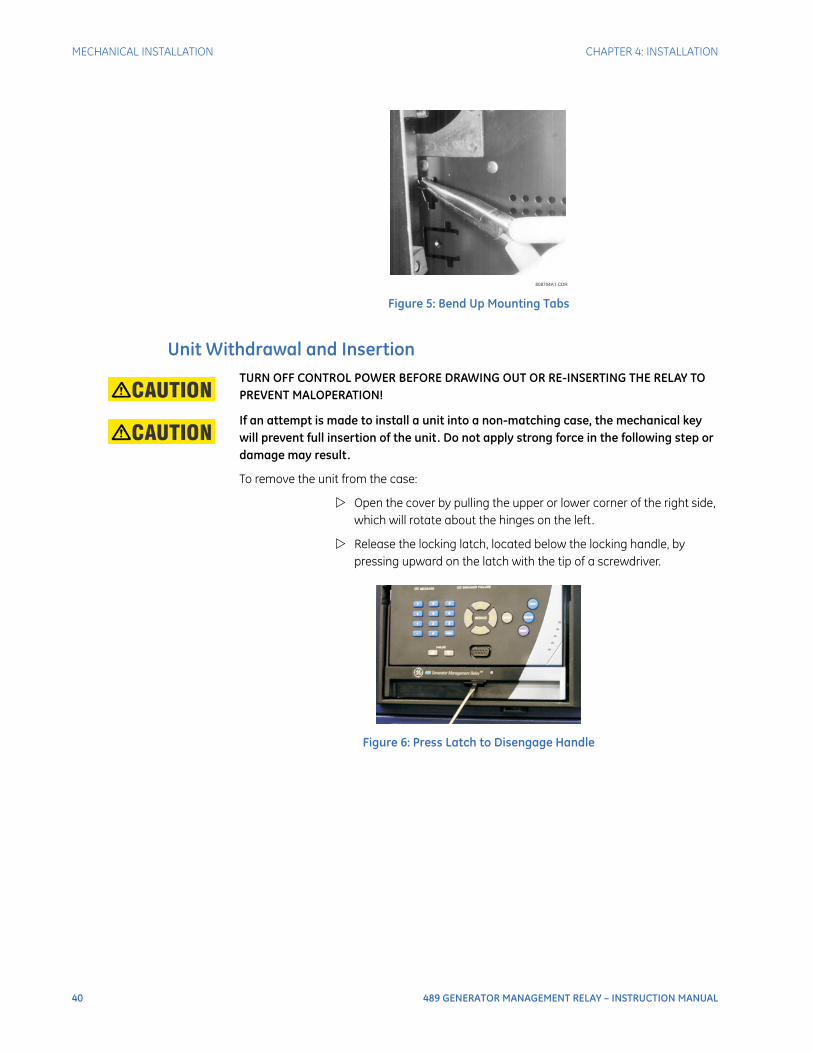
40 489 GENERATOR MANAGEMENT RELAY – INSTRUCTION MANUAL
MECHANICAL INSTALLATION CHAPTER 4: INSTALLATION
Figure 5: Bend Up Mounting Tabs
Unit Withdrawal and InsertionTURN OFF CONTROL POWER BEFORE DRAWING OUT OR RE-INSERTING THE RELAY TO PREVENT MALOPERATION!
If an attempt is made to install a unit into a non-matching case, the mechanical key will prevent full insertion of the unit. Do not apply strong force in the following step or damage may result.
To remove the unit from the case:
Open the cover by pulling the upper or lower corner of the right side, which will rotate about the hinges on the left.
Release the locking latch, located below the locking handle, by pressing upward on the latch with the tip of a screwdriver.
Figure 6: Press Latch to Disengage Handle
808704A1.CDR
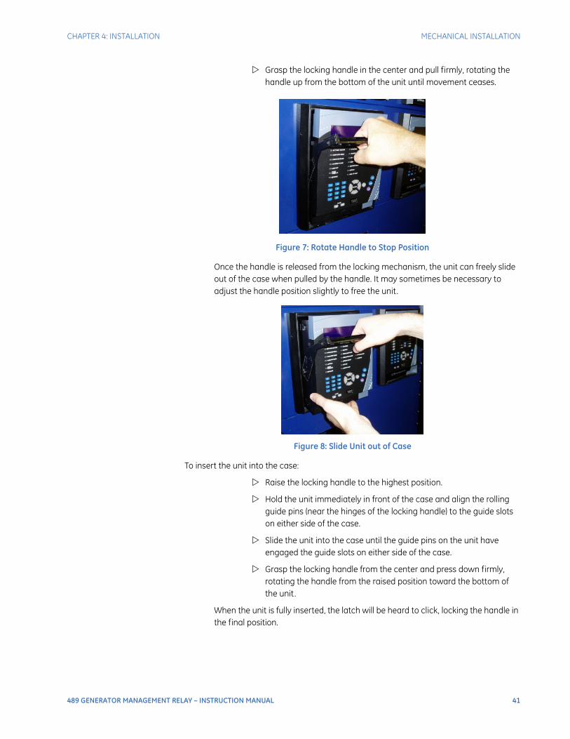
CHAPTER 4: INSTALLATION MECHANICAL INSTALLATION
489 GENERATOR MANAGEMENT RELAY – INSTRUCTION MANUAL 41
Grasp the locking handle in the center and pull firmly, rotating the handle up from the bottom of the unit until movement ceases.
Figure 7: Rotate Handle to Stop Position
Once the handle is released from the locking mechanism, the unit can freely slide out of the case when pulled by the handle. It may sometimes be necessary to adjust the handle position slightly to free the unit.
Figure 8: Slide Unit out of Case
To insert the unit into the case:
Raise the locking handle to the highest position.
Hold the unit immediately in front of the case and align the rolling guide pins (near the hinges of the locking handle) to the guide slots on either side of the case.
Slide the unit into the case until the guide pins on the unit have engaged the guide slots on either side of the case.
Grasp the locking handle from the center and press down firmly, rotating the handle from the raised position toward the bottom of the unit.
When the unit is fully inserted, the latch will be heard to click, locking the handle in the final position.
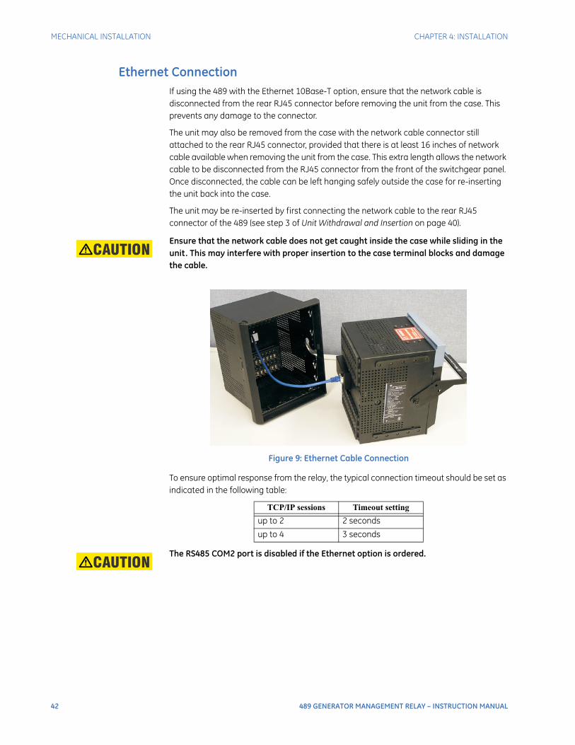
42 489 GENERATOR MANAGEMENT RELAY – INSTRUCTION MANUAL
MECHANICAL INSTALLATION CHAPTER 4: INSTALLATION
Ethernet ConnectionIf using the 489 with the Ethernet 10Base-T option, ensure that the network cable is disconnected from the rear RJ45 connector before removing the unit from the case. This prevents any damage to the connector.
The unit may also be removed from the case with the network cable connector still attached to the rear RJ45 connector, provided that there is at least 16 inches of network cable available when removing the unit from the case. This extra length allows the network cable to be disconnected from the RJ45 connector from the front of the switchgear panel. Once disconnected, the cable can be left hanging safely outside the case for re-inserting the unit back into the case.
The unit may be re-inserted by first connecting the network cable to the rear RJ45 connector of the 489 (see step 3 of Unit Withdrawal and Insertion on page 40).
Ensure that the network cable does not get caught inside the case while sliding in the unit. This may interfere with proper insertion to the case terminal blocks and damage the cable.
Figure 9: Ethernet Cable Connection
To ensure optimal response from the relay, the typical connection timeout should be set as indicated in the following table:
The RS485 COM2 port is disabled if the Ethernet option is ordered.
TCP/IP sessions Timeout setting
up to 2 2 seconds
up to 4 3 seconds
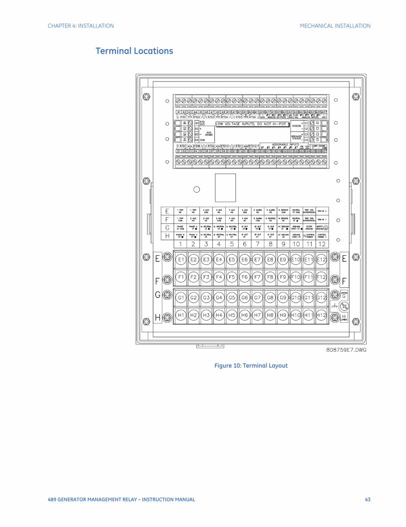
CHAPTER 4: INSTALLATION MECHANICAL INSTALLATION
489 GENERATOR MANAGEMENT RELAY – INSTRUCTION MANUAL 43
Terminal Locations
Figure 10: Terminal Layout

44 489 GENERATOR MANAGEMENT RELAY – INSTRUCTION MANUAL
MECHANICAL INSTALLATION CHAPTER 4: INSTALLATION
Table 4: 489 Terminal List
Terminal Description Terminal Description
A01 RTD #1 Hot D21 Assignable Switch 6
A02 RTD #1 Compensation D22 Assignable Switch 7
A03 RTD Return D23 Switch Common
A04 RTD #2 Compensation D24 Switch +24 V DC
A05 RTD #2 Hot D25 Computer RS485 +
A06 RTD #3 Hot D26 Computer RS485 –
A07 RTD #3 Compensation D27 Computer RS485 Common
A08 RTD Return E01 1 Trip NC
A09 RTD #4 Compensation E02 1 Trip NO
A10 RTD #4 Hot E03 2 Auxiliary Common
A11 RTD #5 Hot E04 3 Auxiliary NC
A12 RTD #5 Compensation E05 3 Auxiliary NO
A13 RTD Return E06 4 Auxiliary Common
A14 RTD #6 Compensation E07 5 Alarm NC
A15 RTD #6 Hot E08 5 Alarm NO
A16 Analog Output Common – E09 6 Service Common
A17 Analog Output 1 + E10 Neutral VT Common
A18 Analog Output 2 + E11 Coil Supervision +
A19 Analog Output 3 + E12 IRIG-B +
A20 Analog Output 4 + F01 1 Trip Common
A21 Analog Shield F02 2 Auxiliary NO
A22 Analog Input 24 V DC Supply + F03 2 Auxiliary NC
A23 Analog Input 1 + F04 3 Auxiliary Common
A24 Analog Input 2 + F05 4 Auxiliary NO
A25 Analog Input 3 + F06 4 Auxiliary NC
A26 Analog Input 4 + F07 5 Alarm Common
A27 Analog Input Common – F08 6 Service NO
B01 RTD Shield F09 6 Service NC
B02 Auxiliary RS485 + F10 Neutral VT +
B03 Auxiliary RS485 – F11 Coil Supervision –
B04 Auxiliary RS485 Common F12 IRIG-B –
C01 Access + G01 Phase VT Common
C02 Access – G02 Phase A VT •
C03 Breaker Status + G03 Neutral Phase A CT •
C04 Breaker Status – G04 Neutral Phase B CT •
D01 RTD #7 Hot G05 Neutral Phase C CT •
D02 RTD #7 Compensation G06 Output Phase A CT •
D03 RTD Return G07 Output Phase B CT •
D04 RTD #8 Compensation G08 Output Phase C CT •
D05 RTD #8 Hot G09 1A Ground CT •
D06 RTD #9 Hot G10 HGF Ground CT •
D07 RTD #9 Compensation G11 Filter Ground
D08 RTD Return G12 Safety Ground
D09 RTD #10 Compensation H01 Phase B VT •
D10 RTD #10 Hot H02 Phase C VT •
D11 RTD #11 Hot H03 Neutral Phase A CT
D12 RTD #11 Compensation H04 Neutral Phase B CT
D13 RTD Return H05 Neutral Phase C CT
D14 RTD #12 Compensation H06 Output Phase A CT
D15 RTD #12 Hot H07 Output Phase B CT
D16 Assignable Switch 1 H08 Output Phase C CT
D17 Assignable Switch 2 H09 1A Ground CT
D18 Assignable Switch 3 H10 HGF Ground CT
D19 Assignable Switch 4 H11 Control Power –
D20 Assignable Switch 5 H12 Control Power +

CHAPTER 4: INSTALLATION ELECTRICAL INSTALLATION
489 GENERATOR MANAGEMENT RELAY – INSTRUCTION MANUAL 45
Electrical Installation
Typical Wiring
Figure 11: Typical Wiring Diagram
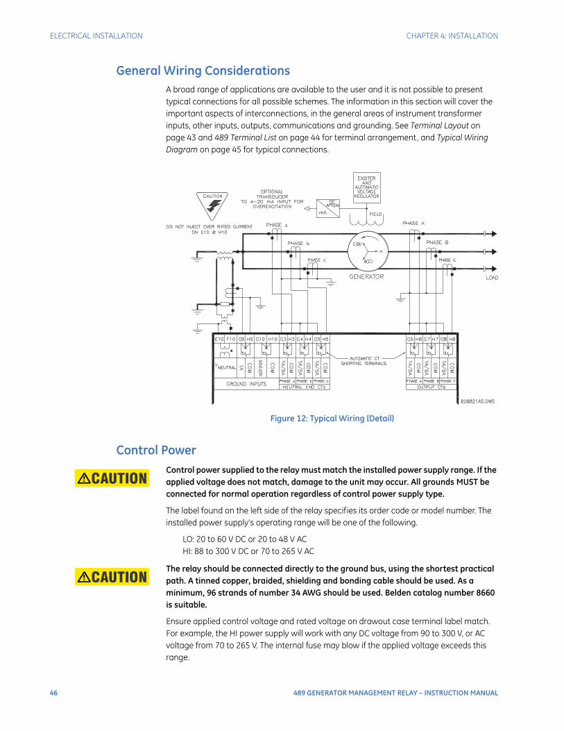
46 489 GENERATOR MANAGEMENT RELAY – INSTRUCTION MANUAL
ELECTRICAL INSTALLATION CHAPTER 4: INSTALLATION
General Wiring ConsiderationsA broad range of applications are available to the user and it is not possible to present typical connections for all possible schemes. The information in this section will cover the important aspects of interconnections, in the general areas of instrument transformer inputs, other inputs, outputs, communications and grounding. See Terminal Layout on page 43 and 489 Terminal List on page 44 for terminal arrangement, and Typical Wiring Diagram on page 45 for typical connections.
Figure 12: Typical Wiring (Detail)
Control PowerControl power supplied to the relay must match the installed power supply range. If the applied voltage does not match, damage to the unit may occur. All grounds MUST be connected for normal operation regardless of control power supply type.
The label found on the left side of the relay specifies its order code or model number. The installed power supply’s operating range will be one of the following.
LO: 20 to 60 V DC or 20 to 48 V ACHI: 88 to 300 V DC or 70 to 265 V AC
The relay should be connected directly to the ground bus, using the shortest practical path. A tinned copper, braided, shielding and bonding cable should be used. As a minimum, 96 strands of number 34 AWG should be used. Belden catalog number 8660 is suitable.
Ensure applied control voltage and rated voltage on drawout case terminal label match. For example, the HI power supply will work with any DC voltage from 90 to 300 V, or AC voltage from 70 to 265 V. The internal fuse may blow if the applied voltage exceeds this range.
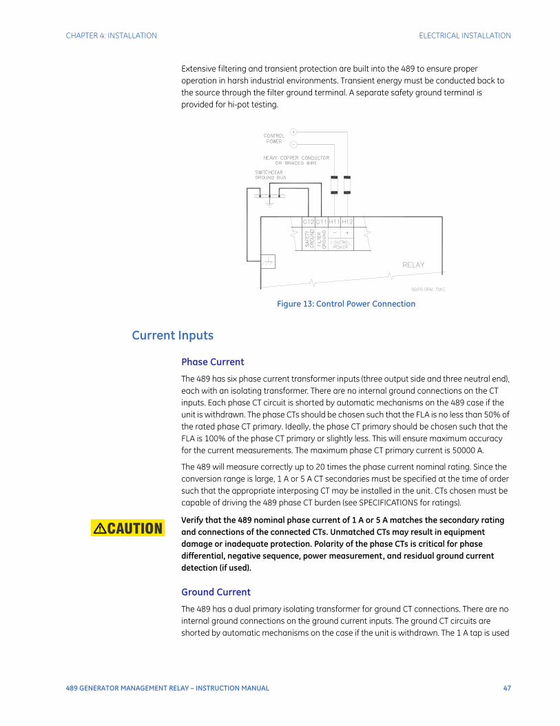
CHAPTER 4: INSTALLATION ELECTRICAL INSTALLATION
489 GENERATOR MANAGEMENT RELAY – INSTRUCTION MANUAL 47
Extensive filtering and transient protection are built into the 489 to ensure proper operation in harsh industrial environments. Transient energy must be conducted back to the source through the filter ground terminal. A separate safety ground terminal is provided for hi-pot testing.
Figure 13: Control Power Connection
Current Inputs
Phase Current
The 489 has six phase current transformer inputs (three output side and three neutral end), each with an isolating transformer. There are no internal ground connections on the CT inputs. Each phase CT circuit is shorted by automatic mechanisms on the 489 case if the unit is withdrawn. The phase CTs should be chosen such that the FLA is no less than 50% of the rated phase CT primary. Ideally, the phase CT primary should be chosen such that the FLA is 100% of the phase CT primary or slightly less. This will ensure maximum accuracy for the current measurements. The maximum phase CT primary current is 50000 A.
The 489 will measure correctly up to 20 times the phase current nominal rating. Since the conversion range is large, 1 A or 5 A CT secondaries must be specified at the time of order such that the appropriate interposing CT may be installed in the unit. CTs chosen must be capable of driving the 489 phase CT burden (see SPECIFICATIONS for ratings).
Verify that the 489 nominal phase current of 1 A or 5 A matches the secondary rating and connections of the connected CTs. Unmatched CTs may result in equipment damage or inadequate protection. Polarity of the phase CTs is critical for phase differential, negative sequence, power measurement, and residual ground current detection (if used).
Ground Current
The 489 has a dual primary isolating transformer for ground CT connections. There are no internal ground connections on the ground current inputs. The ground CT circuits are shorted by automatic mechanisms on the case if the unit is withdrawn. The 1 A tap is used
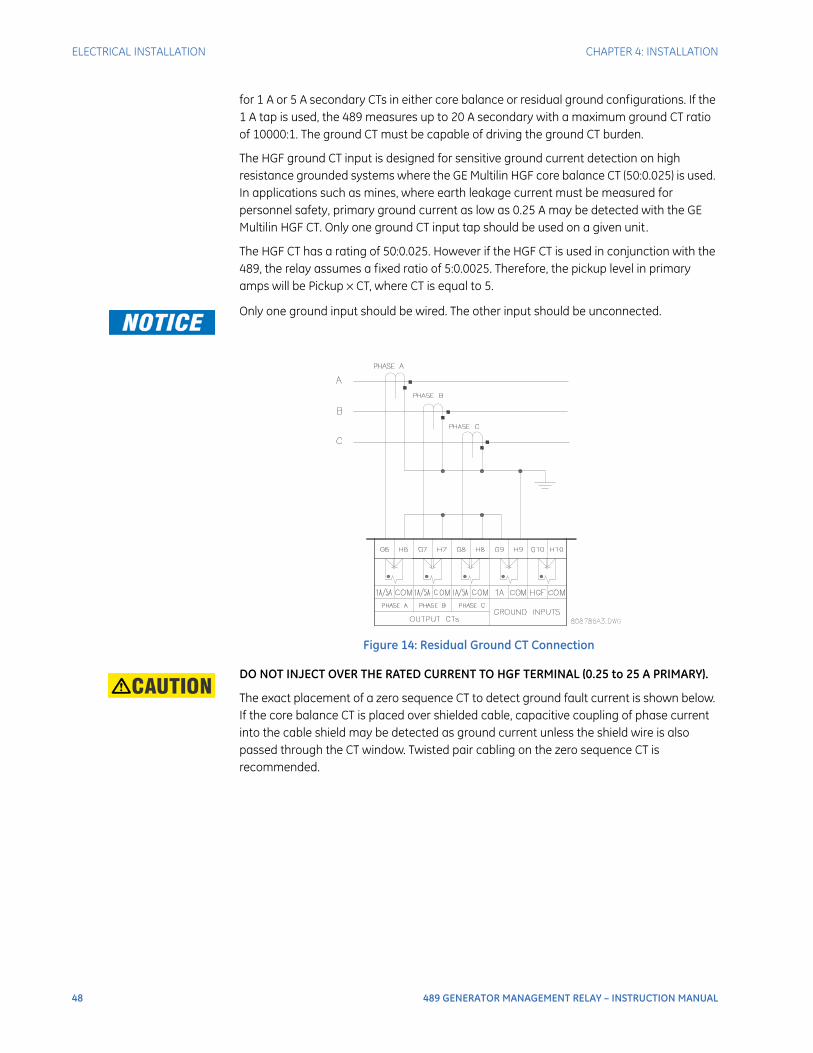
48 489 GENERATOR MANAGEMENT RELAY – INSTRUCTION MANUAL
ELECTRICAL INSTALLATION CHAPTER 4: INSTALLATION
for 1 A or 5 A secondary CTs in either core balance or residual ground configurations. If the 1 A tap is used, the 489 measures up to 20 A secondary with a maximum ground CT ratio of 10000:1. The ground CT must be capable of driving the ground CT burden.
The HGF ground CT input is designed for sensitive ground current detection on high resistance grounded systems where the GE Multilin HGF core balance CT (50:0.025) is used. In applications such as mines, where earth leakage current must be measured for personnel safety, primary ground current as low as 0.25 A may be detected with the GE Multilin HGF CT. Only one ground CT input tap should be used on a given unit.
The HGF CT has a rating of 50:0.025. However if the HGF CT is used in conjunction with the 489, the relay assumes a fixed ratio of 5:0.0025. Therefore, the pickup level in primary amps will be Pickup × CT, where CT is equal to 5.
Only one ground input should be wired. The other input should be unconnected.
Figure 14: Residual Ground CT Connection
DO NOT INJECT OVER THE RATED CURRENT TO HGF TERMINAL (0.25 to 25 A PRIMARY).
The exact placement of a zero sequence CT to detect ground fault current is shown below. If the core balance CT is placed over shielded cable, capacitive coupling of phase current into the cable shield may be detected as ground current unless the shield wire is also passed through the CT window. Twisted pair cabling on the zero sequence CT is recommended.
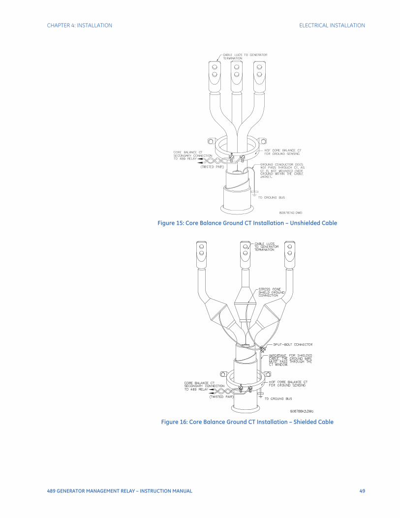
CHAPTER 4: INSTALLATION ELECTRICAL INSTALLATION
489 GENERATOR MANAGEMENT RELAY – INSTRUCTION MANUAL 49
Figure 15: Core Balance Ground CT Installation – Unshielded Cable
Figure 16: Core Balance Ground CT Installation – Shielded Cable
50 489 GENERATOR MANAGEMENT RELAY – INSTRUCTION MANUAL
ELECTRICAL INSTALLATION CHAPTER 4: INSTALLATION
Voltage InputsThe 489 has four voltage transformer inputs, three for generator terminal voltage and one for neutral voltage. There are no internal fuses or ground connections on the voltage inputs. The maximum phase VT ratio is 300.00:1 and the maximum neutral VT ratio is 240.00:1. The two possible VT connections for generator terminal voltage measurement are open delta or wye (see Typical Wiring Diagram on page 45). The voltage channels are connected in wye internally, which means that the jumper shown on the delta-source connection of the Typical Wiring Diagram, between the phase B input and the 489 neutral terminal, must be installed for open delta VTs.
Polarity of the generator terminal VTs is critical for correct power measurement and voltage phase reversal operation.
Digital InputsThere are 9 digital inputs that are designed for dry contact connections only. Two of the digital inputs, Access and Breaker Status have their own common terminal, the balance of the digital inputs share one common terminal (see Typical Wiring Diagram on page 45).
In addition, the +24 V DC switch supply is brought out for control power of an inductive or capacitive proximity probe. The NPN transistor output could be taken to one of the assignable digital inputs configured as a counter or tachometer. Refer to the Specifications section of this manual for maximum current draw from the +24 V DC switch supply.
DO NOT INJECT VOLTAGES TO DIGITAL INPUTS. DRY CONTACT CONNECTIONS ONLY.
Analog InputsTerminals are provided on the 489 for the input of four 0 to 1 mA, 0 to 20 mA, or 4 to 20 mA current signals (field programmable). This current signal can be used to monitor any external quantity such as: vibration, pressure, field current, etc. The four inputs share one common return. Polarity of these inputs must be observed for proper operation The analog input circuitry is isolated as a group with the Analog Output circuitry and the RTD circuitry. Only one ground reference should be used for the three circuits. Transorbs limit this isolation to ±36 V with respect to the 489 safety ground.
In addition, the +24 V DC analog input supply is brought out for control power of loop powered transducers. Refer to the Specifications section of this manual for maximum current draw from this supply.
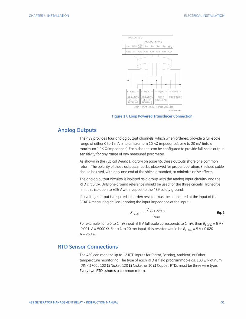
CHAPTER 4: INSTALLATION ELECTRICAL INSTALLATION
489 GENERATOR MANAGEMENT RELAY – INSTRUCTION MANUAL 51
Figure 17: Loop Powered Transducer Connection
Analog OutputsThe 489 provides four analog output channels, which when ordered, provide a full-scale range of either 0 to 1 mA (into a maximum 10 kΩ impedance), or 4 to 20 mA (into a maximum 1.2K Ω impedance). Each channel can be configured to provide full-scale output sensitivity for any range of any measured parameter.
As shown in the Typical Wiring Diagram on page 45, these outputs share one common return. The polarity of these outputs must be observed for proper operation. Shielded cable should be used, with only one end of the shield grounded, to minimize noise effects.
The analog output circuitry is isolated as a group with the Analog Input circuitry and the RTD circuitry. Only one ground reference should be used for the three circuits. Transorbs limit this isolation to ±36 V with respect to the 489 safety ground.
If a voltage output is required, a burden resistor must be connected at the input of the SCADA measuring device. Ignoring the input impedance of the input:
Eq. 1
For example, for a 0 to 1 mA input, if 5 V full scale corresponds to 1 mA, then RLOAD = 5 V /0.001 A = 5000 Ω. For a 4 to 20 mA input, this resistor would be RLOAD = 5 V / 0.020
A = 250 Ω.
RTD Sensor ConnectionsThe 489 can monitor up to 12 RTD inputs for Stator, Bearing, Ambient, or Other temperature monitoring. The type of each RTD is field programmable as: 100 Ω Platinum (DIN 43760), 100 Ω Nickel, 120 Ω Nickel, or 10 Ω Copper. RTDs must be three wire type. Every two RTDs shares a common return.
RLOADVFULL-SCALE
IMAX------------------------------=
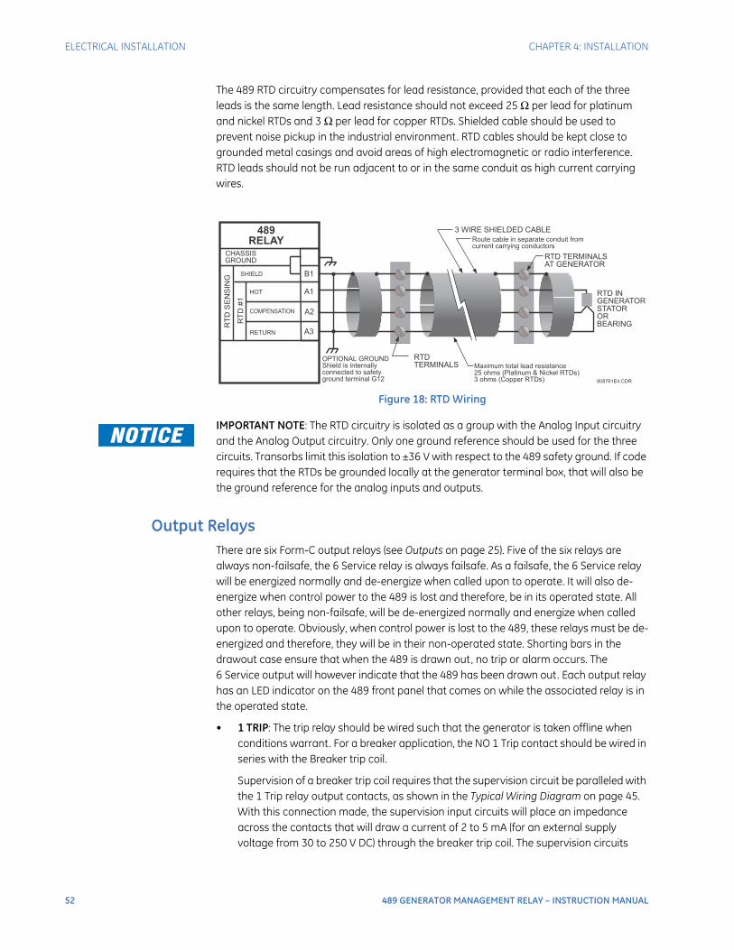
52 489 GENERATOR MANAGEMENT RELAY – INSTRUCTION MANUAL
ELECTRICAL INSTALLATION CHAPTER 4: INSTALLATION
The 489 RTD circuitry compensates for lead resistance, provided that each of the three leads is the same length. Lead resistance should not exceed 25 Ω per lead for platinum and nickel RTDs and 3 Ω per lead for copper RTDs. Shielded cable should be used to prevent noise pickup in the industrial environment. RTD cables should be kept close to grounded metal casings and avoid areas of high electromagnetic or radio interference. RTD leads should not be run adjacent to or in the same conduit as high current carrying wires.
Figure 18: RTD Wiring
IMPORTANT NOTE: The RTD circuitry is isolated as a group with the Analog Input circuitry and the Analog Output circuitry. Only one ground reference should be used for the three circuits. Transorbs limit this isolation to ±36 V with respect to the 489 safety ground. If code requires that the RTDs be grounded locally at the generator terminal box, that will also be the ground reference for the analog inputs and outputs.
Output RelaysThere are six Form-C output relays (see Outputs on page 25). Five of the six relays are always non-failsafe, the 6 Service relay is always failsafe. As a failsafe, the 6 Service relay will be energized normally and de-energize when called upon to operate. It will also de-energize when control power to the 489 is lost and therefore, be in its operated state. All other relays, being non-failsafe, will be de-energized normally and energize when called upon to operate. Obviously, when control power is lost to the 489, these relays must be de-energized and therefore, they will be in their non-operated state. Shorting bars in the drawout case ensure that when the 489 is drawn out, no trip or alarm occurs. The 6 Service output will however indicate that the 489 has been drawn out. Each output relay has an LED indicator on the 489 front panel that comes on while the associated relay is in the operated state.
• 1 TRIP: The trip relay should be wired such that the generator is taken offline when conditions warrant. For a breaker application, the NO 1 Trip contact should be wired in series with the Breaker trip coil.
Supervision of a breaker trip coil requires that the supervision circuit be paralleled with the 1 Trip relay output contacts, as shown in the Typical Wiring Diagram on page 45. With this connection made, the supervision input circuits will place an impedance across the contacts that will draw a current of 2 to 5 mA (for an external supply voltage from 30 to 250 V DC) through the breaker trip coil. The supervision circuits
3 WIRE SHIELDED CABLE
RTD
TERMINALS
RTD TERMINALS
AT GENERATOR
Maximum total lead resistance
25 ohms (Platinum & Nickel RTDs)
3 ohms (Copper RTDs)
OPTIONAL GROUND
Shield is internally
connected to safety
ground terminal G12
Route cable in separate conduit from
current carrying conductors
RTD IN
GENERATOR
STATOR
OR
BEARING
808761E4.CDR
B1
A1
A2
A3
HOT
COMPENSATION
RETURN
SHIELD
CHASSIS
GROUND
RT
DS
EN
SIN
G
RT
D#1
489
RELAY
CHAPTER 4: INSTALLATION ELECTRICAL INSTALLATION
489 GENERATOR MANAGEMENT RELAY – INSTRUCTION MANUAL 53
respond to a loss of this trickle current as a failure condition. Circuit breakers equipped with standard control circuits have a breaker auxiliary contact permitting the trip coil to be energized only when the breaker is closed. When these contacts are open, as detected by the Breaker Status digital input, trip coil supervision circuit is automatically disabled. This logic provides that the trip circuit is monitored only when the breaker is closed.
• 2 AUXILIARY, 3 AUXILIARY, 4 AUXILIARY: The auxiliary relays may be programmed for numerous functions such as, trip echo, alarm echo, trip backup, alarm or trip differentiation, control circuitry, etc. They should be wired as configuration warrants.
• 5 ALARM: The alarm relay should connect to the appropriate annunciator or monitoring device.
• 6 SERVICE: The service relay will operate if any of the 489 diagnostics detect an internal failure or on loss of control power. This output may be monitored with an annunciator, PLC or DCS.
The service relay NC contact may also be wired in parallel with the trip relay on a breaker application. This will provide failsafe operation of the generator; that is, the generator will be tripped offline in the event that the 489 is not protecting it . Simple annunciation of such a failure will allow the operator or the operation computer to either continue, or do a sequenced shutdown.
Relay contacts must be considered unsafe to touch when the system is energized! If the customer requires the relay contacts for low voltage accessible applications, it is their responsibility to ensure proper insulation levels.
IRIG-BIRIG-B is a standard time-code format that allows stamping of events to be synchronized among connected devices within 1 millisecond. The IRIG-B time codes are serial, width-modulated formats which are either DC level shifted or amplitude modulated (AM). Third party equipment is available for generating the IRIG-B signal. This equipment may use a GPS satellite system to obtain the time reference enabling devices at different geographic locations to be synchronized.
Terminals E12 and F12 on the 489 unit are provided for the connection of an IRIG-B signal.
RS485 PortsTwo independent two-wire RS485 ports are provided. Up to 32 489 relays can be daisy-chained together on a communication channel without exceeding the driver capability. For larger systems, additional serial channels must be added. It is also possible to use commercially available repeaters to increase the number of relays on a single channel to more than 32. A suitable cable should have a characteristic impedance of 120 Ω (e.g. Belden #9841) and total wire length should not exceed 4000 feet (approximately 1200 metres). Commercially available repeaters will allow for transmission distances greater than 4000 ft.
Voltage differences between remote ends of the communication link are not uncommon. For this reason, surge protection devices are internally installed across all RS485 terminals. Internally, an isolated power supply with an optocoupled data interface is used to prevent noise coupling.
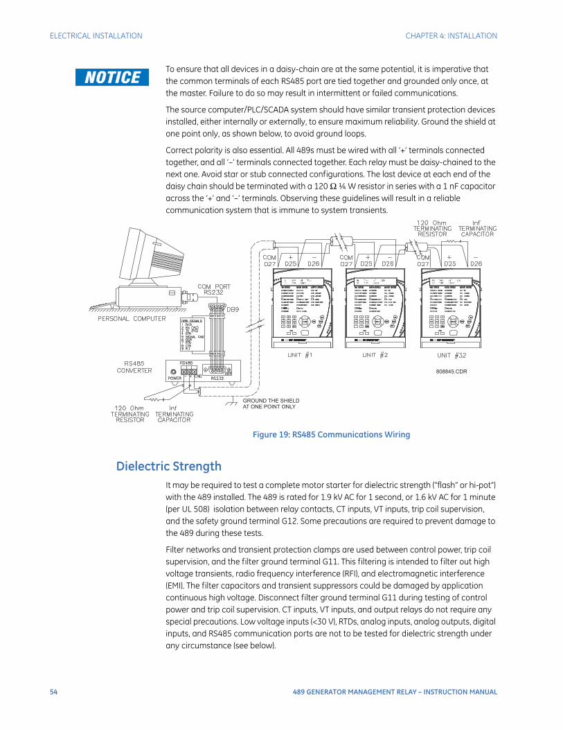
54 489 GENERATOR MANAGEMENT RELAY – INSTRUCTION MANUAL
ELECTRICAL INSTALLATION CHAPTER 4: INSTALLATION
To ensure that all devices in a daisy-chain are at the same potential, it is imperative that the common terminals of each RS485 port are tied together and grounded only once, at the master. Failure to do so may result in intermittent or failed communications.
The source computer/PLC/SCADA system should have similar transient protection devices installed, either internally or externally, to ensure maximum reliability. Ground the shield at one point only, as shown below, to avoid ground loops.
Correct polarity is also essential. All 489s must be wired with all ‘+’ terminals connected together, and all ‘–’ terminals connected together. Each relay must be daisy-chained to the next one. Avoid star or stub connected configurations. The last device at each end of the daisy chain should be terminated with a 120 Ω ¼ W resistor in series with a 1 nF capacitor across the ‘+’ and ‘–’ terminals. Observing these guidelines will result in a reliable communication system that is immune to system transients.
Figure 19: RS485 Communications Wiring
Dielectric StrengthIt may be required to test a complete motor starter for dielectric strength (“flash” or hi-pot”) with the 489 installed. The 489 is rated for 1.9 kV AC for 1 second, or 1.6 kV AC for 1 minute (per UL 508) isolation between relay contacts, CT inputs, VT inputs, trip coil supervision, and the safety ground terminal G12. Some precautions are required to prevent damage to the 489 during these tests.
Filter networks and transient protection clamps are used between control power, trip coil supervision, and the filter ground terminal G11. This filtering is intended to filter out high voltage transients, radio frequency interference (RFI), and electromagnetic interference (EMI). The filter capacitors and transient suppressors could be damaged by application continuous high voltage. Disconnect filter ground terminal G11 during testing of control power and trip coil supervision. CT inputs, VT inputs, and output relays do not require any special precautions. Low voltage inputs (<30 V), RTDs, analog inputs, analog outputs, digital inputs, and RS485 communication ports are not to be tested for dielectric strength under any circumstance (see below).
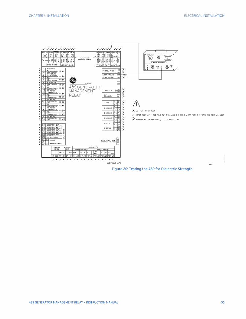
CHAPTER 4: INSTALLATION ELECTRICAL INSTALLATION
489 GENERATOR MANAGEMENT RELAY – INSTRUCTION MANUAL 55
Figure 20: Testing the 489 for Dielectric Strength
g GE Multilin

56 489 GENERATOR MANAGEMENT RELAY – INSTRUCTION MANUAL
ELECTRICAL INSTALLATION CHAPTER 4: INSTALLATION

489 GENERATOR MANAGEMENT RELAY – INSTRUCTION MANUAL 57
489 Generator Management Relay
Chapter 5: Interfaces
Interfaces
Faceplate Interface
DisplayAll messages appear on a 40-character liquid crystal display. Messages are in plain English and do not require the aid of an instruction manual for deciphering. When the user interface is not being used, the display defaults to the user-defined status messages. Any trip or alarm automatically overrides the default messages and is immediately displayed.
LED IndicatorsThere are three groups of LED indicators. They are 489 Status, Generator Status, and Output Status.
Figure 21: 489 LED Indicators
808732A3.CDR

58 489 GENERATOR MANAGEMENT RELAY – INSTRUCTION MANUAL
FACEPLATE INTERFACE CHAPTER 5: INTERFACES
489 Status LED Indicators
• 489 IN SERVICE: Indicates that control power is applied, all monitored input/output and internal systems are OK, the 489 has been programmed, and is in protection mode, not simulation mode. When in simulation or testing mode, the LED indicator will flash.
• SETPOINT ACCESS: Indicates that the access jumper is installed and passcode protection has been satisfied. Setpoints may be altered and stored.
• COMPUTER RS232: Flashes when there is any activity on the RS232 communications port. Remains on continuously if incoming data is valid.
• COMPUTER RS485 / AUXILIARY RS485: Flashes when there is any activity on the computer/auxiliary RS485 communications port. These LEDs remain on continuously if incoming data is valid and intended for the slave address programmed in the relay.
• ALT. SETPOINTS: Flashes when the alternate setpoint group is being edited and the primary setpoint group is active. Remains on continuously if the alternate setpoint group is active. The alternate setpoint group feature is enabled as one of the assignable digital inputs. The alternate setpoints group can be selected by setting the S3 DIGITAL INPUTS DUAL SETPOINTS ACTIVE SETPOINT GROUP setpoint to “Group 2”.
• RESET POSSIBLE: A trip or latched alarm may be reset. Pressing the RESET key clears the trip/alarm.
• MESSAGE: Under normal conditions, the default messages selected during setpoint programming are displayed. If any alarm or trip condition is generated, a diagnostic message overrides the displayed message and this indicator flashes. If there is more than one condition present, MESSAGE can be used to scroll through the messages. Pressing any other key returns to the normally displayed messages. While viewing normally displayed messages, the Message LED continues to flash if any diagnostic message is active.
To return to the diagnostic messages from the normally displayed messages, press the MENU key until the following message is displayed:
Now, press the MESSAGE key followed by the message key to scroll through the messages. Note that diagnostic messages for alarms disappear with the condition while diagnostic messages for trips remain until cleared by a reset.
Generator Status LED Indicators
• BREAKER OPEN: Uses the breaker status input signal to indicate that the breaker is open and the generator is offline.
• BREAKER CLOSED: Uses the breaker status input signal to indicate that the breaker is closed and the generator is online.
3. TARGET MESSAGESPress [] for more

CHAPTER 5: INTERFACES FACEPLATE INTERFACE
489 GENERATOR MANAGEMENT RELAY – INSTRUCTION MANUAL 59
• HOT STATOR: Indicates that the generator stator is above normal temperature when one of the stator RTD alarm or trip elements is picked up or the thermal model trip element is picked up.
• NEG. SEQUENCE: Indicates that the negative sequence current alarm or trip element is picked up.
• GROUND: Indicates that at least one of the ground overcurrent, neutral overvoltage (fundamental), or neutral undervoltage (3rd harmonic) alarm/trip elements is picked up.
• LOSS OF FIELD: Indicates that at least one of the reactive power (kvar) or field-breaker discrepancy alarm/trip elements is picked up.
• VT FAILURE: Indicates that the VT fuse failure alarm is picked up.
• BREAKER FAILURE: Indicates that the breaker failure or trip coil monitor alarm is picked up.
Output Status LED Indicators
• 1 TRIP: The 1 Trip relay has operated (energized).
• 2 AUXILIARY: The 2 Auxiliary relay has operated (energized).
• 3 AUXILIARY: The 3 Auxiliary relay has operated (energized).
• 4 AUXILIARY: The 4 Auxiliary relay has operated (energized).
• 5 ALARM: The 5 Alarm relay has operated (energized).
• 6 SERVICE: The 6 Service relay has operated (de-energized, 6 Service is fail-safe, normally energized).
RS232 Program PortThis port is intended for connection to a portable PC. Setpoint files may be created at any location and downloaded through this port with the EnerVista 489 Setup software. Local interrogation of setpoint and actual values is also possible. New firmware may be downloaded to the 489 flash memory through this port. Upgrading the relay firmware does not require a hardware EEPROM change.
Keypad
Description
The 489 display messages are organized into main menus, pages, and sub-pages. There are three main menus labeled Setpoints, Actual Values, and Target Messages.
Press the MENU key followed by the MESSAGE key to scroll through the three main menu headers, which appear in sequence as follows:
1. SETPOINTSPress [] for more
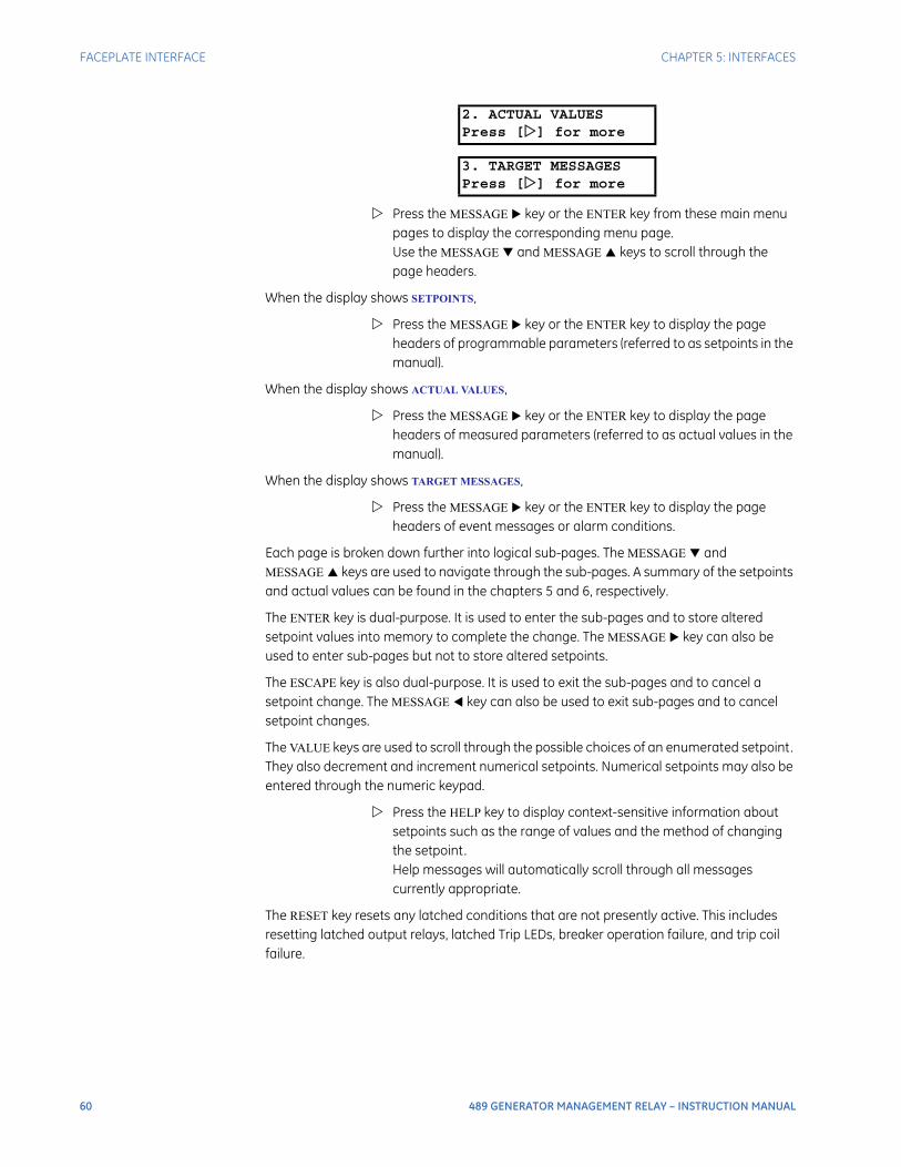
60 489 GENERATOR MANAGEMENT RELAY – INSTRUCTION MANUAL
FACEPLATE INTERFACE CHAPTER 5: INTERFACES
Press the MESSAGE key or the ENTER key from these main menu pages to display the corresponding menu page. Use the MESSAGE and MESSAGE keys to scroll through the page headers.
When the display shows SETPOINTS,
Press the MESSAGE key or the ENTER key to display the page headers of programmable parameters (referred to as setpoints in the manual).
When the display shows ACTUAL VALUES,
Press the MESSAGE key or the ENTER key to display the page headers of measured parameters (referred to as actual values in the manual).
When the display shows TARGET MESSAGES,
Press the MESSAGE key or the ENTER key to display the page headers of event messages or alarm conditions.
Each page is broken down further into logical sub-pages. The MESSAGE and MESSAGE keys are used to navigate through the sub-pages. A summary of the setpoints and actual values can be found in the chapters 5 and 6, respectively.
The ENTER key is dual-purpose. It is used to enter the sub-pages and to store altered setpoint values into memory to complete the change. The MESSAGE key can also be used to enter sub-pages but not to store altered setpoints.
The ESCAPE key is also dual-purpose. It is used to exit the sub-pages and to cancel a setpoint change. The MESSAGE key can also be used to exit sub-pages and to cancel setpoint changes.
The VALUE keys are used to scroll through the possible choices of an enumerated setpoint. They also decrement and increment numerical setpoints. Numerical setpoints may also be entered through the numeric keypad.
Press the HELP key to display context-sensitive information about setpoints such as the range of values and the method of changing the setpoint. Help messages will automatically scroll through all messages currently appropriate.
The RESET key resets any latched conditions that are not presently active. This includes resetting latched output relays, latched Trip LEDs, breaker operation failure, and trip coil failure.
2. ACTUAL VALUESPress [] for more
3. TARGET MESSAGESPress [] for more

CHAPTER 5: INTERFACES FACEPLATE INTERFACE
489 GENERATOR MANAGEMENT RELAY – INSTRUCTION MANUAL 61
The MESSAGE and MESSAGE keys scroll through any active conditions in the relay. Diagnostic messages are displayed indicating the state of protection and monitoring elements that are picked up, operating, or latched. When the Message LED is on, there are messages to be viewed with the MENU key by selecting target messages as described earlier.
Entering Alphanumeric Text
Text setpoints have data values that are fixed in length but user-defined in character. They may be comprised of upper case letters, lower case letters, numerals, and a selection of special characters. The editing and storing of a text value is accomplished with the use of the decimal [.], VALUE, and ENTER keys.
Move to message S3 DIGITAL INPUTS GENERAL INPUT A ASSIGN
DIGITAL INPUT, and scrolling with the VALUE keys, select “Input 1”. The relay will display the following message:
Press the MESSAGE key to view the INPUT NAME setpoint. The name of this user-defined input will be changed in this example from the generic “Input A” to something more descriptive.
If an application is to be using the relay as a station monitor, it is more informative to rename this input “Stn. Monitor”.
Press the decimal [.] to enter the text editing mode. The first character will appear underlined as follows:
Press the VALUE keys until the character “S” is displayed in the first position.
Press the decimal [.] key to store the character and advance the cursor to the next position.
Change the second character to a “t” in the same manner.
Continue entering characters in this way until all characters of the text “Stn. Monitor” are entered. Note that a space is selected like a character. If a character is entered incorrectly, press the decimal [.] key repeatedly until the cursor returns to the position of the error. Re-enter the character as required.
Once complete, press the ENTER key to remove the solid cursor and view the result. Once a character is entered, by pressing the ENTER key, it is automatically saved in Flash Memory, as a new setpoint.
ASSIGN DIGITALINPUT: Input 1
INPUT NAME:Input A
INPUT NAME:Stn. Monitor
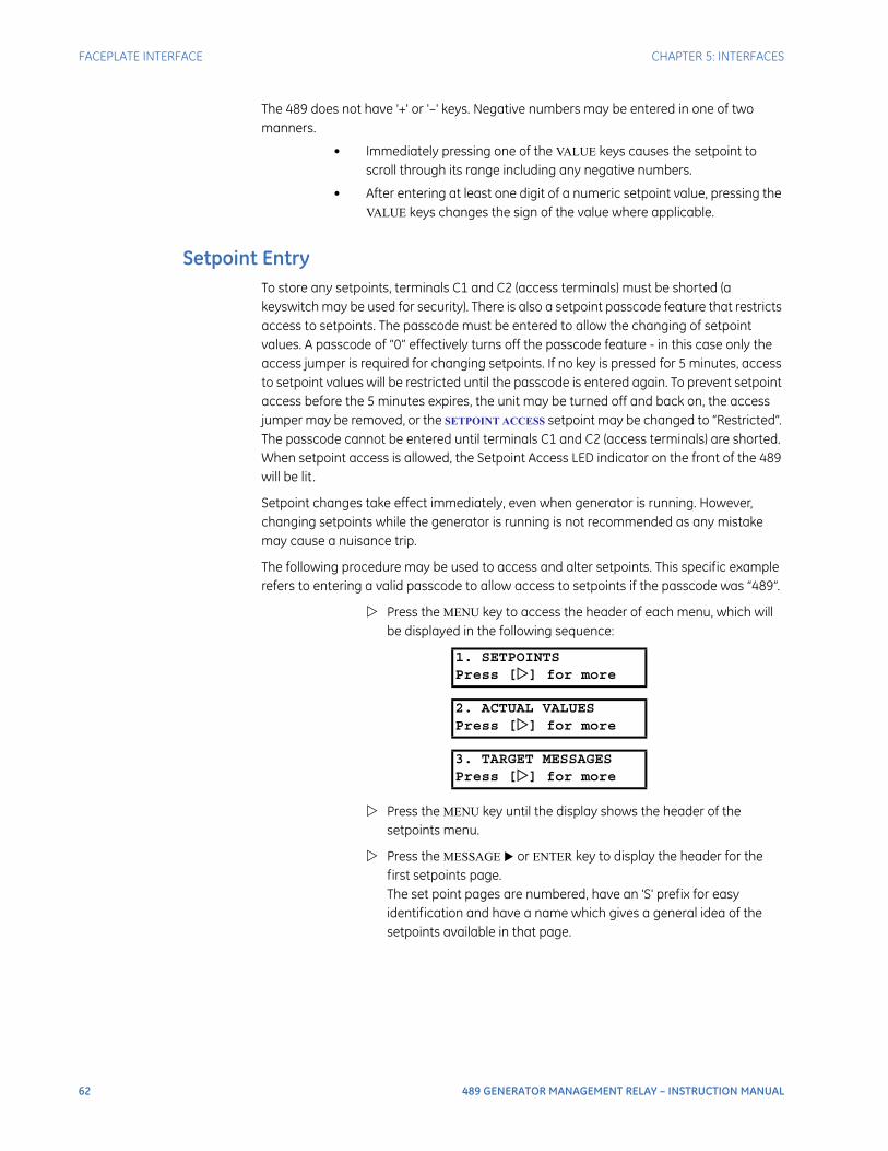
62 489 GENERATOR MANAGEMENT RELAY – INSTRUCTION MANUAL
FACEPLATE INTERFACE CHAPTER 5: INTERFACES
The 489 does not have '+' or '–' keys. Negative numbers may be entered in one of two manners.
• Immediately pressing one of the VALUE keys causes the setpoint to scroll through its range including any negative numbers.
• After entering at least one digit of a numeric setpoint value, pressing the VALUE keys changes the sign of the value where applicable.
Setpoint EntryTo store any setpoints, terminals C1 and C2 (access terminals) must be shorted (a keyswitch may be used for security). There is also a setpoint passcode feature that restricts access to setpoints. The passcode must be entered to allow the changing of setpoint values. A passcode of “0” effectively turns off the passcode feature - in this case only the access jumper is required for changing setpoints. If no key is pressed for 5 minutes, access to setpoint values will be restricted until the passcode is entered again. To prevent setpoint access before the 5 minutes expires, the unit may be turned off and back on, the access jumper may be removed, or the SETPOINT ACCESS setpoint may be changed to “Restricted”. The passcode cannot be entered until terminals C1 and C2 (access terminals) are shorted. When setpoint access is allowed, the Setpoint Access LED indicator on the front of the 489 will be lit .
Setpoint changes take effect immediately, even when generator is running. However, changing setpoints while the generator is running is not recommended as any mistake may cause a nuisance trip.
The following procedure may be used to access and alter setpoints. This specific example refers to entering a valid passcode to allow access to setpoints if the passcode was “489”.
Press the MENU key to access the header of each menu, which will be displayed in the following sequence:
Press the MENU key until the display shows the header of the setpoints menu.
Press the MESSAGE or ENTER key to display the header for the first setpoints page. The set point pages are numbered, have an 'S' prefix for easy identification and have a name which gives a general idea of the setpoints available in that page.
1. SETPOINTSPress [] for more
2. ACTUAL VALUESPress [] for more
3. TARGET MESSAGESPress [] for more

CHAPTER 5: INTERFACES FACEPLATE INTERFACE
489 GENERATOR MANAGEMENT RELAY – INSTRUCTION MANUAL 63
Press the MESSAGE or MESSAGE keys to scroll through all the available setpoint page headers. Setpoint page headers look as follows:
To enter a given setpoints page,
Press the MESSAGE or ENTER key.
Press the MESSAGE or MESSAGE keys to scroll through sub-page headers until the required message is reached. The end of a page is indicated by the message END OF PAGE. The beginning of a page is indicated by the message TOP OF PAGE.
Each page is broken further into subgroups.
Press MESSAGE or MESSAGE to cycle through subgroups until the desired subgroup appears on the screen.
Press the MESSAGE or ENTER key to enter a subgroup.
Each sub-group has one or more associated setpoint messages.
Press the MESSAGE or MESSAGE keys to scroll through setpoint messages until the desired message appears.
The majority of setpoints are changed by pressing the VALUE keys until the desired value appears, and then pressing ENTER. Numeric setpoints may also be entered through the numeric keys (including decimals). If the entered setpoint is out of range, the original setpoint value reappears. If the entered setpoint is out of step, an adjusted value will be stored (e.g. 101 for a setpoint that steps 95, 100, 105 is stored as 100). If a mistake is made entering the new value, pressing ESCAPE returns the setpoint to its original value. Text editing is a special case described in detail in Entering Alphanumeric Text on page 61. Each time a new setpoint is successfully stored, a message will flash on the display stating NEW SETPOINT HAS BEEN STORED.
Press the 4, 8, 9 keys, then press ENTER. The following flash message is displayed:
and the display returns to:
Press ESCAPE or MESSAGE to exit the subgroup. Pressing ESCAPE or MESSAGE numerous times will always return the cursor to the top of the page.
SETPOINTS []S1 489 SETUP
PASSCODE []
ENTER PASSCODEFOR ACCESS:
NEW SETPOINTHAS BEEN STORED
SETPOINT ACCESS:PERMITTED
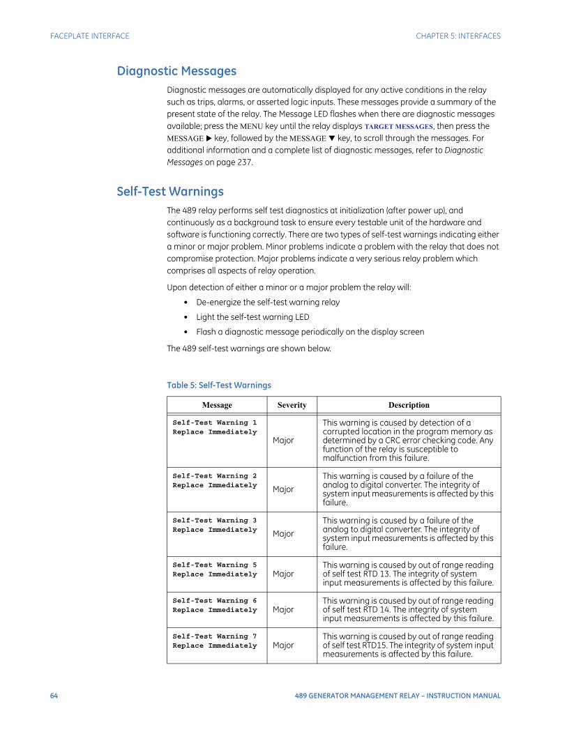
64 489 GENERATOR MANAGEMENT RELAY – INSTRUCTION MANUAL
FACEPLATE INTERFACE CHAPTER 5: INTERFACES
Diagnostic MessagesDiagnostic messages are automatically displayed for any active conditions in the relay such as trips, alarms, or asserted logic inputs. These messages provide a summary of the present state of the relay. The Message LED flashes when there are diagnostic messages available; press the MENU key until the relay displays TARGET MESSAGES, then press the MESSAGE key, followed by the MESSAGE key, to scroll through the messages. For additional information and a complete list of diagnostic messages, refer to Diagnostic Messages on page 237.
Self-Test WarningsThe 489 relay performs self test diagnostics at initialization (after power up), and continuously as a background task to ensure every testable unit of the hardware and software is functioning correctly. There are two types of self-test warnings indicating either a minor or major problem. Minor problems indicate a problem with the relay that does not compromise protection. Major problems indicate a very serious relay problem which comprises all aspects of relay operation.
Upon detection of either a minor or a major problem the relay will:
• De-energize the self-test warning relay
• Light the self-test warning LED
• Flash a diagnostic message periodically on the display screen
The 489 self-test warnings are shown below.
Table 5: Self-Test Warnings
Message Severity Description
Self-Test Warning 1Replace Immediately
Major
This warning is caused by detection of a corrupted location in the program memory as determined by a CRC error checking code. Any function of the relay is susceptible to malfunction from this failure.
Self-Test Warning 2Replace Immediately Major
This warning is caused by a failure of the analog to digital converter. The integrity of system input measurements is affected by this failure.
Self-Test Warning 3Replace Immediately Major
This warning is caused by a failure of the analog to digital converter. The integrity of system input measurements is affected by this failure.
Self-Test Warning 5Replace Immediately Major
This warning is caused by out of range reading of self test RTD 13. The integrity of system input measurements is affected by this failure.
Self-Test Warning 6Replace Immediately Major
This warning is caused by out of range reading of self test RTD 14. The integrity of system input measurements is affected by this failure.
Self-Test Warning 7Replace Immediately Major
This warning is caused by out of range reading of self test RTD15. The integrity of system input measurements is affected by this failure.
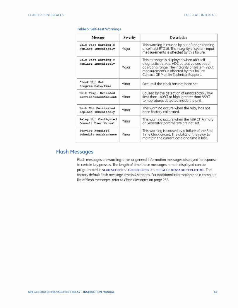
CHAPTER 5: INTERFACES FACEPLATE INTERFACE
489 GENERATOR MANAGEMENT RELAY – INSTRUCTION MANUAL 65
Flash MessagesFlash messages are warning, error, or general information messages displayed in response to certain key presses. The length of time these messages remain displayed can be programmed in S1 489 SETUP PREFERENCES DEFAULT MESSAGE CYCLE TIME. The factory default flash message time is 4 seconds. For additional information and a complete list of flash messages, refer to Flash Messages on page 238.
Self-Test Warning 8Replace Immediately Major
This warning is caused by out of range reading of self test RTD16. The integrity of system input measurements is affected by this failure.
Self-Test Warning 9Replace Immediately
Major
This message is displayed when 489 self diagnostic detects ADC output values out of operating range. The integrity of system input measurements is affected by this failure. Contact GE Multilin Technical Support.
Clock Not SetProgram Date/Time
Minor Occurs if the clock has not been set.
Unit Temp. ExceededService/CheckAmbient Minor
Caused by the detection of unacceptably low (less than –40°C) or high (greater than 85°C) temperatures detected inside the unit.
Unit Not CalibratedReplace Immediately
Minor This warning occurs when the relay has not been factory calibrated.
Relay Not ConfiguredConsult User Manual
Minor This warning occurs when the 489 CT Primary or Generator parameters are not set.
Service RequiredSchedule Maintenance Minor
This warning is caused by a failure of the Real Time Clock circuit. The ability of the relay to maintain the current date and time is lost.
Table 5: Self-Test Warnings
Message Severity Description

66 489 GENERATOR MANAGEMENT RELAY – INSTRUCTION MANUAL
ENERVISTA SOFTWARE INTERFACE CHAPTER 5: INTERFACES
EnerVista Software Interface
OverviewThe front panel provides local operator interface with a liquid crystal display. The EnerVista 489 Setup software provides a graphical user interface (GUI) as one of two human interfaces to a 489 device. The alternate human interface is implemented via the device's faceplate keypad and display (see the first section in this chapter).
The EnerVista 489 Setup software provides a single facility to configure, monitor, maintain, and trouble-shoot the operation of relay functions, connected over serial communication networks. It can be used while disconnected (i.e. off-line) or connected (i.e. on-line) to a 489 device. In off-line mode, setpoint files can be created for eventual downloading to the device. In on-line mode, you can communicate with the device in real-time.
This no-charge software, provided with every 489 relay, can be run from any computer supporting Microsoft Windows 95 or higher. This chapter provides a summary of the basic EnerVista 489 Setup software interface features. The EnerVista 489 Setup help file provides details for getting started and using the software interface.
With the EnerVista 489 Setup running on your PC, it is possible to
• Program and modify setpoints
• Load/save setpoint files from/to disk
• Read actual values and monitor status
• Perform waveform capture and log data
• Plot, print, and view trending graphs of selected actual values
• Download and playback waveforms
• Get help on any topic
HardwareCommunications from the EnerVista 489 Setup to the 489 can be accomplished three ways: RS232, RS485, and Ethernet (requires the MultiNet adapter) communications. The following figures below illustrate typical connections for RS232 and RS485 communications. For additional details on Ethernet communications, please see the MultiNet manual (GE Publication number GEK-106498).
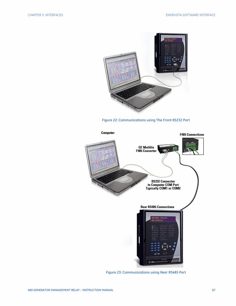
CHAPTER 5: INTERFACES ENERVISTA SOFTWARE INTERFACE
489 GENERATOR MANAGEMENT RELAY – INSTRUCTION MANUAL 67
Figure 22: Communications using The Front RS232 Port
Figure 23: Communications using Rear RS485 Port
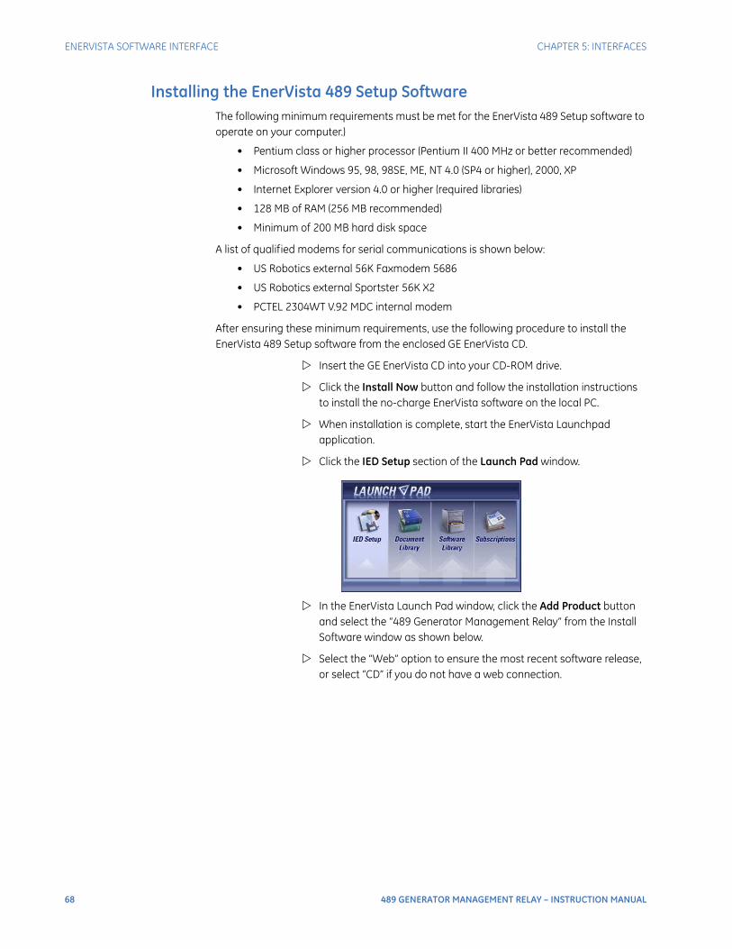
68 489 GENERATOR MANAGEMENT RELAY – INSTRUCTION MANUAL
ENERVISTA SOFTWARE INTERFACE CHAPTER 5: INTERFACES
Installing the EnerVista 489 Setup SoftwareThe following minimum requirements must be met for the EnerVista 489 Setup software to operate on your computer.)
• Pentium class or higher processor (Pentium II 400 MHz or better recommended)
• Microsoft Windows 95, 98, 98SE, ME, NT 4.0 (SP4 or higher), 2000, XP
• Internet Explorer version 4.0 or higher (required libraries)
• 128 MB of RAM (256 MB recommended)
• Minimum of 200 MB hard disk space
A list of qualified modems for serial communications is shown below:
• US Robotics external 56K Faxmodem 5686
• US Robotics external Sportster 56K X2
• PCTEL 2304WT V.92 MDC internal modem
After ensuring these minimum requirements, use the following procedure to install the EnerVista 489 Setup software from the enclosed GE EnerVista CD.
Insert the GE EnerVista CD into your CD-ROM drive.
Click the Install Now button and follow the installation instructions to install the no-charge EnerVista software on the local PC.
When installation is complete, start the EnerVista Launchpad application.
Click the IED Setup section of the Launch Pad window.
In the EnerVista Launch Pad window, click the Add Product button and select the “489 Generator Management Relay” from the Install Software window as shown below.
Select the “Web” option to ensure the most recent software release, or select “CD” if you do not have a web connection.
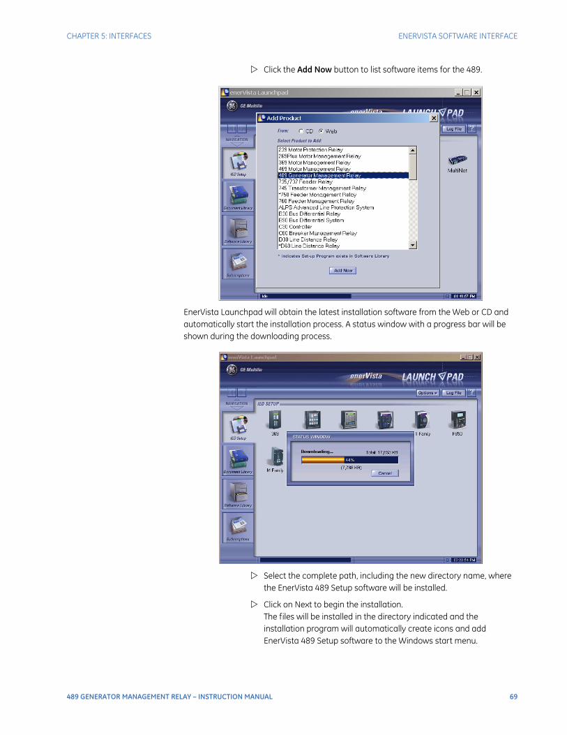
CHAPTER 5: INTERFACES ENERVISTA SOFTWARE INTERFACE
489 GENERATOR MANAGEMENT RELAY – INSTRUCTION MANUAL 69
Click the Add Now button to list software items for the 489.
EnerVista Launchpad will obtain the latest installation software from the Web or CD and automatically start the installation process. A status window with a progress bar will be shown during the downloading process.
Select the complete path, including the new directory name, where the EnerVista 489 Setup software will be installed.
Click on Next to begin the installation. The files will be installed in the directory indicated and the installation program will automatically create icons and add EnerVista 489 Setup software to the Windows start menu.
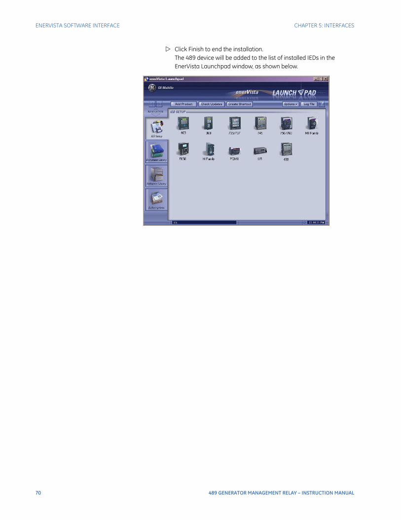
70 489 GENERATOR MANAGEMENT RELAY – INSTRUCTION MANUAL
ENERVISTA SOFTWARE INTERFACE CHAPTER 5: INTERFACES
Click Finish to end the installation. The 489 device will be added to the list of installed IEDs in the EnerVista Launchpad window, as shown below.
CHAPTER 5: INTERFACES CONNECTING ENERVISTA 489 SETUP TO THE RELAY
489 GENERATOR MANAGEMENT RELAY – INSTRUCTION MANUAL 71
Connecting EnerVista 489 Setup to the Relay
Configuring Serial CommunicationsBefore starting, verify that the serial cable is properly connected to either the RS232 port on the front panel of the device (for RS232 communications) or to the RS485 terminals on the back of the device (for RS485 communications). See Hardware on page 66 for connection details.
This example demonstrates an RS232 connection. For RS485 communications, the GE Multilin F485 converter will be required. Refer to the F485 manual for additional details. To configure the relay for Ethernet communications, see Configuring Ethernet Communications on page 73.
Install and start the latest version of the EnerVista 489 Setup software (available from the GE EnerVista CD). See the previous section for the installation procedure.
Click on the Device Setup button to open the Device Setup window.
Click the Add Site button to define a new site.
Enter the desired site name in the Site Name field. If desired, a short description of site can also be entered along with the display order of devices defined for the site. In this example, we will use “Pumping Station 1” as the site name.
Click the OK button when complete.
The new site will appear in the upper-left list in the EnerVista 489 Setup window.
Click the Add Device button to define the new device.
Enter the desired name in the Device Name field and a description (optional) of the site.

72 489 GENERATOR MANAGEMENT RELAY – INSTRUCTION MANUAL
CONNECTING ENERVISTA 489 SETUP TO THE RELAY CHAPTER 5: INTERFACES
Select “Serial” from the Interface drop-down list. This will display a number of interface parameters that must be entered for proper RS232 functionality.
Enter the slave address and COM port values (from the S1 489 SETUP
COMMUNICATIONS menu) in the Slave Address and COM Port fields.
Enter the physical communications parameters (baud rate and parity setpoints) in their respective fields. Note that when communicating to the relay from the front port, the default communications setpoints are a baud rate of 9600, with slave address of 1, no parity, 8 bits, and 1 stop bit. These values cannot be changed.
Click the Read Order Code button to connect to the 489 device and upload the order code. If a communications error occurs, ensure that the 489 serial communications values entered in the previous step correspond to the relay setting values.
Click OK when the relay order code has been received. The new device will be added to the Site List window (or Online window) located in the top left corner of the main EnerVista 489 Setup window.
The 489 Site Device has now been configured for serial communications. Proceed to Connecting to the Relay on page 75 to begin communications.
Using the Quick Connect FeatureThe Quick Connect button can be used to establish a fast connection through the front panel RS232 port of a 489 relay.
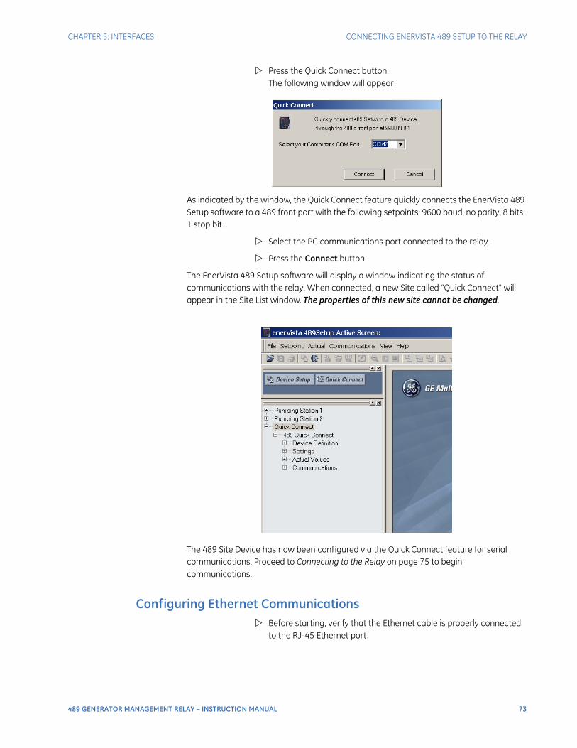
CHAPTER 5: INTERFACES CONNECTING ENERVISTA 489 SETUP TO THE RELAY
489 GENERATOR MANAGEMENT RELAY – INSTRUCTION MANUAL 73
Press the Quick Connect button.The following window will appear:
As indicated by the window, the Quick Connect feature quickly connects the EnerVista 489 Setup software to a 489 front port with the following setpoints: 9600 baud, no parity, 8 bits, 1 stop bit.
Select the PC communications port connected to the relay.
Press the Connect button.
The EnerVista 489 Setup software will display a window indicating the status of communications with the relay. When connected, a new Site called “Quick Connect” will appear in the Site List window. The properties of this new site cannot be changed.
The 489 Site Device has now been configured via the Quick Connect feature for serial communications. Proceed to Connecting to the Relay on page 75 to begin communications.
Configuring Ethernet Communications Before starting, verify that the Ethernet cable is properly connected
to the RJ-45 Ethernet port.
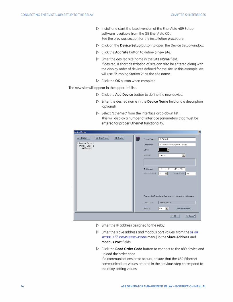
74 489 GENERATOR MANAGEMENT RELAY – INSTRUCTION MANUAL
CONNECTING ENERVISTA 489 SETUP TO THE RELAY CHAPTER 5: INTERFACES
Install and start the latest version of the EnerVista 489 Setup software (available from the GE EnerVista CD). See the previous section for the installation procedure.
Click on the Device Setup button to open the Device Setup window.
Click the Add Site button to define a new site.
Enter the desired site name in the Site Name field. If desired, a short description of site can also be entered along with the display order of devices defined for the site. In this example, we will use “Pumping Station 2” as the site name.
Click the OK button when complete.
The new site will appear in the upper-left list.
Click the Add Device button to define the new device.
Enter the desired name in the Device Name field and a description (optional).
Select “Ethernet” from the Interface drop-down list. This will display a number of interface parameters that must be entered for proper Ethernet functionality.
Enter the IP address assigned to the relay.
Enter the slave address and Modbus port values (from the S1 489
SETUP COMMUNICATIONS menu) in the Slave Address and Modbus Port fields.
Click the Read Order Code button to connect to the 489 device and upload the order code. If a communications error occurs, ensure that the 489 Ethernet communications values entered in the previous step correspond to the relay setting values.
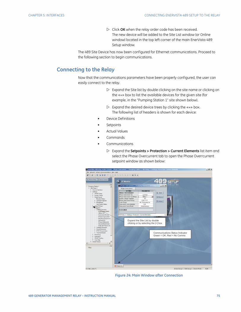
CHAPTER 5: INTERFACES CONNECTING ENERVISTA 489 SETUP TO THE RELAY
489 GENERATOR MANAGEMENT RELAY – INSTRUCTION MANUAL 75
Click OK when the relay order code has been received. The new device will be added to the Site List window (or Online window) located in the top left corner of the main EnerVista 489 Setup window.
The 489 Site Device has now been configured for Ethernet communications. Proceed to the following section to begin communications.
Connecting to the RelayNow that the communications parameters have been properly configured, the user can easily connect to the relay.
Expand the Site list by double clicking on the site name or clicking on the «+» box to list the available devices for the given site (for example, in the “Pumping Station 1” site shown below).
Expand the desired device trees by clicking the «+» box. The following list of headers is shown for each device:
• Device Definitions
• Setpoints
• Actual Values
• Commands
• Communications
Expand the Setpoints > Protection > Current Elements list item and select the Phase Overcurrent tab to open the Phase Overrcurrent setpoint window as shown below:
Figure 24: Main Window after Connection
-Expand the Site List by double
clicking or by selecting the [+] box
Communications Status Indicator
Green = OK, Red = No Comms

76 489 GENERATOR MANAGEMENT RELAY – INSTRUCTION MANUAL
CONNECTING ENERVISTA 489 SETUP TO THE RELAY CHAPTER 5: INTERFACES
The Phase Overcurrent setpoint window will open with a corresponding status indicator on the lower left of the EnerVista 489 Setup window.
If the status indicator is red, verify that the serial cable is properly connected to the relay, and that the relay has been properly configured for communications (steps described earlier).
Setpoints can now be edited, printed, or changed according to user specifications. Other setpoint and commands windows can be displayed and edited in a similar manner. Actual values windows are also available for display. These windows can be locked, arranged, and resized at will.
Refer to the EnerVista 489 Setup help file for additional information about using the software.
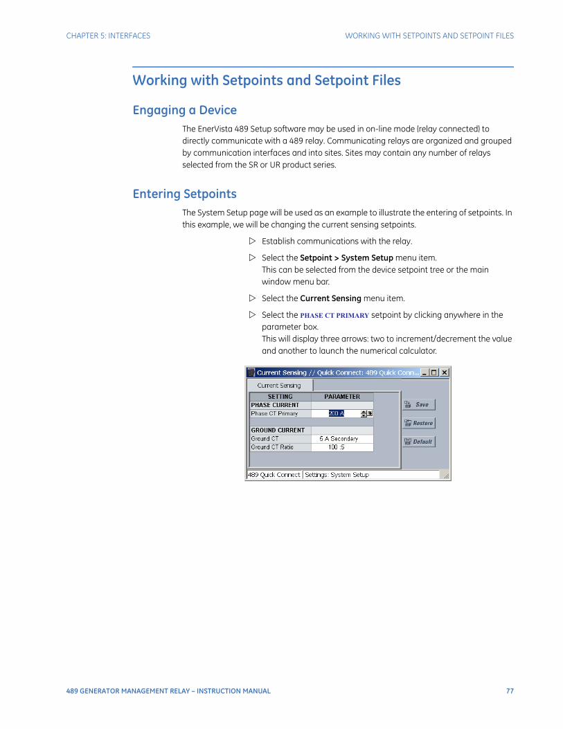
CHAPTER 5: INTERFACES WORKING WITH SETPOINTS AND SETPOINT FILES
489 GENERATOR MANAGEMENT RELAY – INSTRUCTION MANUAL 77
Working with Setpoints and Setpoint Files
Engaging a DeviceThe EnerVista 489 Setup software may be used in on-line mode (relay connected) to directly communicate with a 489 relay. Communicating relays are organized and grouped by communication interfaces and into sites. Sites may contain any number of relays selected from the SR or UR product series.
Entering SetpointsThe System Setup page will be used as an example to illustrate the entering of setpoints. In this example, we will be changing the current sensing setpoints.
Establish communications with the relay.
Select the Setpoint > System Setup menu item. This can be selected from the device setpoint tree or the main window menu bar.
Select the Current Sensing menu item.
Select the PHASE CT PRIMARY setpoint by clicking anywhere in the parameter box. This will display three arrows: two to increment/decrement the value and another to launch the numerical calculator.

78 489 GENERATOR MANAGEMENT RELAY – INSTRUCTION MANUAL
WORKING WITH SETPOINTS AND SETPOINT FILES CHAPTER 5: INTERFACES
Click the arrow at the end of the box to display a numerical keypad interface that allows the user to enter a value within the setpoint range displayed near the top of the keypad:
Click Accept to exit from the keypad and keep the new value.
Click on Cancel to exit from the keypad and retain the old value.
For setpoints requiring non-numerical pre-set values (e.g. VT CONNECTION TYPE below, in the Voltage Sensing window),
Click anywhere within the setpoint value box to display a drop-down selection menu arrow.
Click on the arrow to select the desired setpoint.
For setpoints requiring an alphanumeric text string (e.g. message scratchpad messages), the value may be entered directly within the setpoint value box.
In the Setpoint / System Setup dialog box, click on Save to save the values into the 489.
Click Yes to accept any changes.
Click No, and then Restore to retain previous values and exit.

CHAPTER 5: INTERFACES WORKING WITH SETPOINTS AND SETPOINT FILES
489 GENERATOR MANAGEMENT RELAY – INSTRUCTION MANUAL 79
Using Setpoint Files
Overview
The EnerVista 489 Setup software interface supports three ways of handling changes to relay setpoints:
• In off-line mode (relay disconnected) to create or edit relay setpoint files for later download to communicating relays.
• Directly modifying relay setpoints while connected to a communicating relay, then saving the setpoints when complete.
• Creating/editing setpoint files while connected to a communicating relay, then saving them to the relay when complete.
Settings files are organized on the basis of file names assigned by the user. A settings file contains data pertaining to the following types of relay settings:
• Device Definition
• Product Setup
• System Setup
• Digital Inputs
• Output Relays
• Voltage Elements
• Power Elements
• RTD Temperature
• Thermal Model
• Monitoring Functions
• Analog Inputs and Outputs
• Relay Testing
• User Memory Map Setting Tool
Factory default values are supplied and can be restored after any changes.
The EnerVista 489 Setup display relay setpoints with the same hierarchy as the front panel display. For specific details on setpoints, refer to Chapter 5.
Downloading and Saving Setpoints Files
Setpoints must be saved to a file on the local PC before performing any firmware upgrades. Saving setpoints is also highly recommended before making any setpoint changes or creating new setpoint files.
The EnerVista 489 Setup window, setpoint files are accessed in the Setpoints List control bar window or the Files window. Use the following procedure to download and save setpoint files to a local PC.
Ensure that the site and corresponding device(s) have been properly defined and configured as shown in Connecting EnerVista 489 Setup to the Relay on page 71.
Select the desired device from the site list.

80 489 GENERATOR MANAGEMENT RELAY – INSTRUCTION MANUAL
WORKING WITH SETPOINTS AND SETPOINT FILES CHAPTER 5: INTERFACES
Select the File > Read Settings from Device menu item to obtain settings information from the device.
After a few seconds of data retrieval, the software will request the name and destination path of the setpoint file. The corresponding file extension will be automatically assigned.
Press Save to complete the process. A new entry will be added to the tree, in the File pane, showing path and file name for the setpoint file.
Adding Setpoints Files to the Environment
The EnerVista 489 Setup software provides the capability to review and manage a large group of setpoint files. Use the following procedure to add a new or existing file to the list.
In the files pane, right-click on ‘Files’
Select the Add Existing Setting File item as shown:
The Open dialog box will appear, prompting for a previously saved setting file. As for any other Windows® application,
Browse for the file to add.
Click Open. The new file and complete path will be added to the file list.
Creating a New Setpoint File
The EnerVista 489 Setup software allows the user to create new setpoint files independent of a connected device. These can be uploaded to a relay at a later date. The following procedure illustrates how to create new setpoint files.
In the File pane, right click on ‘File’.

CHAPTER 5: INTERFACES WORKING WITH SETPOINTS AND SETPOINT FILES
489 GENERATOR MANAGEMENT RELAY – INSTRUCTION MANUAL 81
Select the New Settings File item. The EnerVista 489 Setup software displays the following box, allowing for the configuration of the setpoint file for the correct firmware version. It is important to define the correct firmware version to ensure that setpoints not available in a particular version are not downloaded into the relay.
Select the Firmware Version for the new setpoint file.
For future reference, enter some useful information in the Description box to facilitate the identification of the device and the purpose of the file.
To select a file name and path for the new file, click the button beside the Enter File Name box.
Select the file name and path to store the file, or select any displayed file name to update an existing file. All 489 setpoint files should have the extension ‘489’ (for example, ‘motor1.489’).
Click Save and OK to complete the process. Once this step is completed, the new file, with a complete path, will be added to the EnerVista 489 Setup software environment.
Upgrading Setpoint Files to a New Revision
It is often necessary to upgrade the revision code for a previously saved setpoint file after the 489 firmware has been upgraded (for example, this is required for firmware upgrades). This is illustrated in the following procedure.
Establish communications with the 489 relay.
Select the Actual > Product Information menu item and record the Software Revision identifier of the relay firmware as shown below.
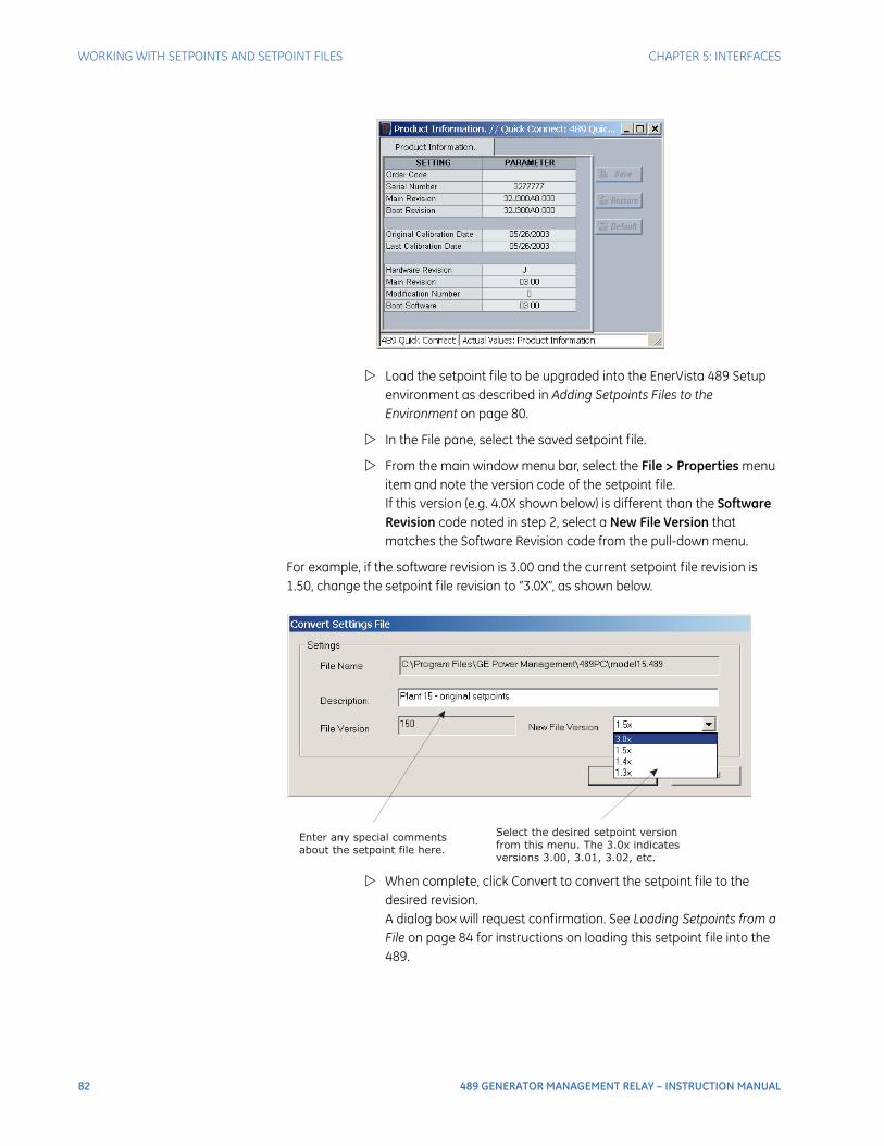
82 489 GENERATOR MANAGEMENT RELAY – INSTRUCTION MANUAL
WORKING WITH SETPOINTS AND SETPOINT FILES CHAPTER 5: INTERFACES
Load the setpoint file to be upgraded into the EnerVista 489 Setup environment as described in Adding Setpoints Files to the Environment on page 80.
In the File pane, select the saved setpoint file.
From the main window menu bar, select the File > Properties menu item and note the version code of the setpoint file. If this version (e.g. 4.0X shown below) is different than the Software Revision code noted in step 2, select a New File Version that matches the Software Revision code from the pull-down menu.
For example, if the software revision is 3.00 and the current setpoint file revision is 1.50, change the setpoint file revision to “3.0X”, as shown below.
When complete, click Convert to convert the setpoint file to the desired revision. A dialog box will request confirmation. See Loading Setpoints from a File on page 84 for instructions on loading this setpoint file into the 489.
Select the desired setpoint version
from this menu. The 3.0x indicates
versions 3.00, 3.01, 3.02, etc.
Enter any special comments
about the setpoint file here.
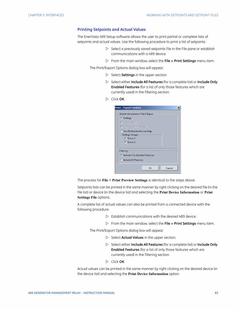
CHAPTER 5: INTERFACES WORKING WITH SETPOINTS AND SETPOINT FILES
489 GENERATOR MANAGEMENT RELAY – INSTRUCTION MANUAL 83
Printing Setpoints and Actual Values
The EnerVista 489 Setup software allows the user to print partial or complete lists of setpoints and actual values. Use the following procedure to print a list of setpoints:
Select a previously saved setpoints file in the File pane or establish communications with a 489 device.
From the main window, select the File > Print Settings menu item.
The Print/Export Options dialog box will appear.
Select Settings in the upper section.
Select either Include All Features (for a complete list) or Include Only Enabled Features (for a list of only those features which are currently used) in the filtering section.
Click OK.
The process for File > Print Preview Settings is identical to the steps above.
Setpoints lists can be printed in the same manner by right clicking on the desired file (in the file list) or device (in the device list) and selecting the Print Device Information or Print Settings File options.
A complete list of actual values can also be printed from a connected device with the following procedure:
Establish communications with the desired 489 device.
From the main window, select the File > Print Settings menu item.
The Print/Export Options dialog box will appear.
Select Actual Values in the upper section.
Select either Include All Features (for a complete list) or Include Only Enabled Features (for a list of only those features which are currently used) in the filtering section.
Click OK.
Actual values can be printed in the same manner by right clicking on the desired device (in the device list) and selecting the Print Device Information option.

84 489 GENERATOR MANAGEMENT RELAY – INSTRUCTION MANUAL
WORKING WITH SETPOINTS AND SETPOINT FILES CHAPTER 5: INTERFACES
Loading Setpoints from a File
An error message will occur when attempting to download a setpoint file with a revision number that does not match the relay firmware. If the firmware has been upgraded since saving the setpoint file, see Upgrading Setpoint Files to a New Revision on page 81 for instructions on changing the revision number of a setpoint file.
The following procedure illustrates how to load setpoints from a file. Before loading a setpoint file, it must first be added to the EnerVista 489 Setup environment as described in Adding Setpoints Files to the Environment on page 80.
Select the previously saved setpoint file from the File pane of the EnerVista 489 Setup software main window.
Select the File > Properties menu item and verify that the corresponding file is fully compatible with the hardware and firmware version of the target relay. If the versions are not identical, see Upgrading Setpoint Files to a New Revision on page 81 for details on changing the setpoints file version.
Right-click on the selected file.
Select the Write Settings to Device item.
The software will prompt for a target device.
Select the desired device.
Click Send.
If there is an incompatibility, an error of the following type will occur.
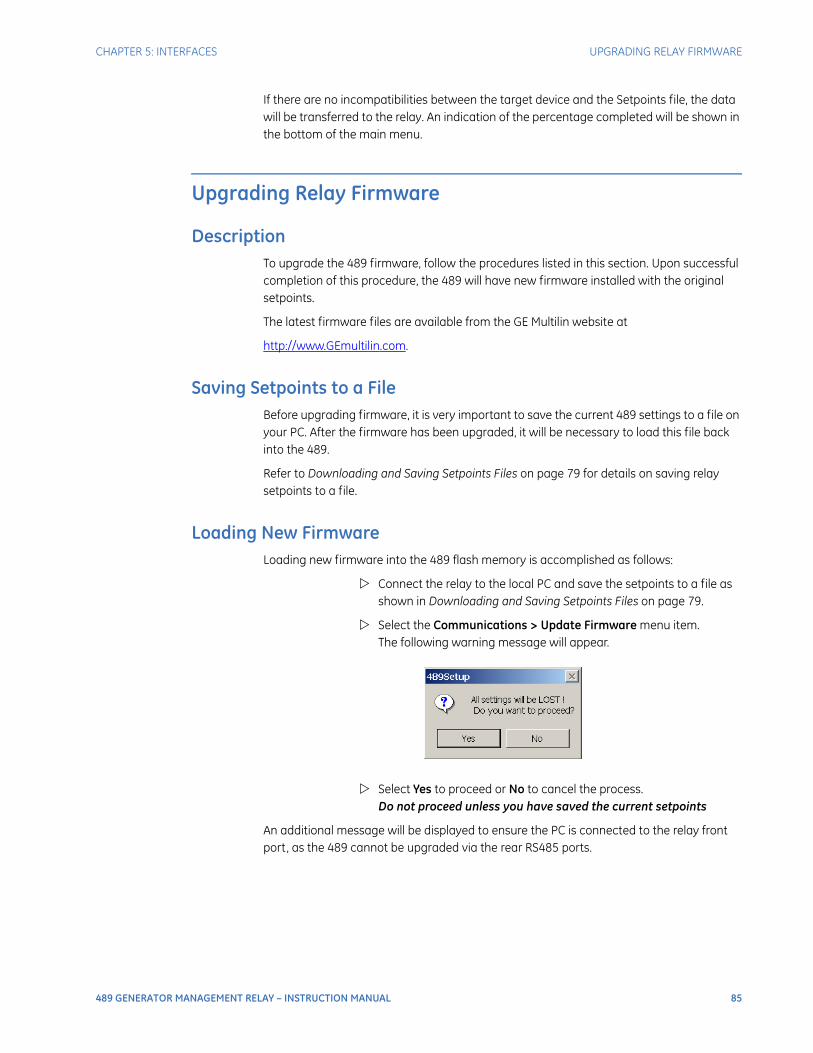
CHAPTER 5: INTERFACES UPGRADING RELAY FIRMWARE
489 GENERATOR MANAGEMENT RELAY – INSTRUCTION MANUAL 85
If there are no incompatibilities between the target device and the Setpoints file, the data will be transferred to the relay. An indication of the percentage completed will be shown in the bottom of the main menu.
Upgrading Relay Firmware
DescriptionTo upgrade the 489 firmware, follow the procedures listed in this section. Upon successful completion of this procedure, the 489 will have new firmware installed with the original setpoints.
The latest firmware files are available from the GE Multilin website at
http://www.GEmultilin.com.
Saving Setpoints to a FileBefore upgrading firmware, it is very important to save the current 489 settings to a file on your PC. After the firmware has been upgraded, it will be necessary to load this file back into the 489.
Refer to Downloading and Saving Setpoints Files on page 79 for details on saving relay setpoints to a file.
Loading New FirmwareLoading new firmware into the 489 flash memory is accomplished as follows:
Connect the relay to the local PC and save the setpoints to a file as shown in Downloading and Saving Setpoints Files on page 79.
Select the Communications > Update Firmware menu item.The following warning message will appear.
Select Yes to proceed or No to cancel the process. Do not proceed unless you have saved the current setpoints
An additional message will be displayed to ensure the PC is connected to the relay front port, as the 489 cannot be upgraded via the rear RS485 ports.
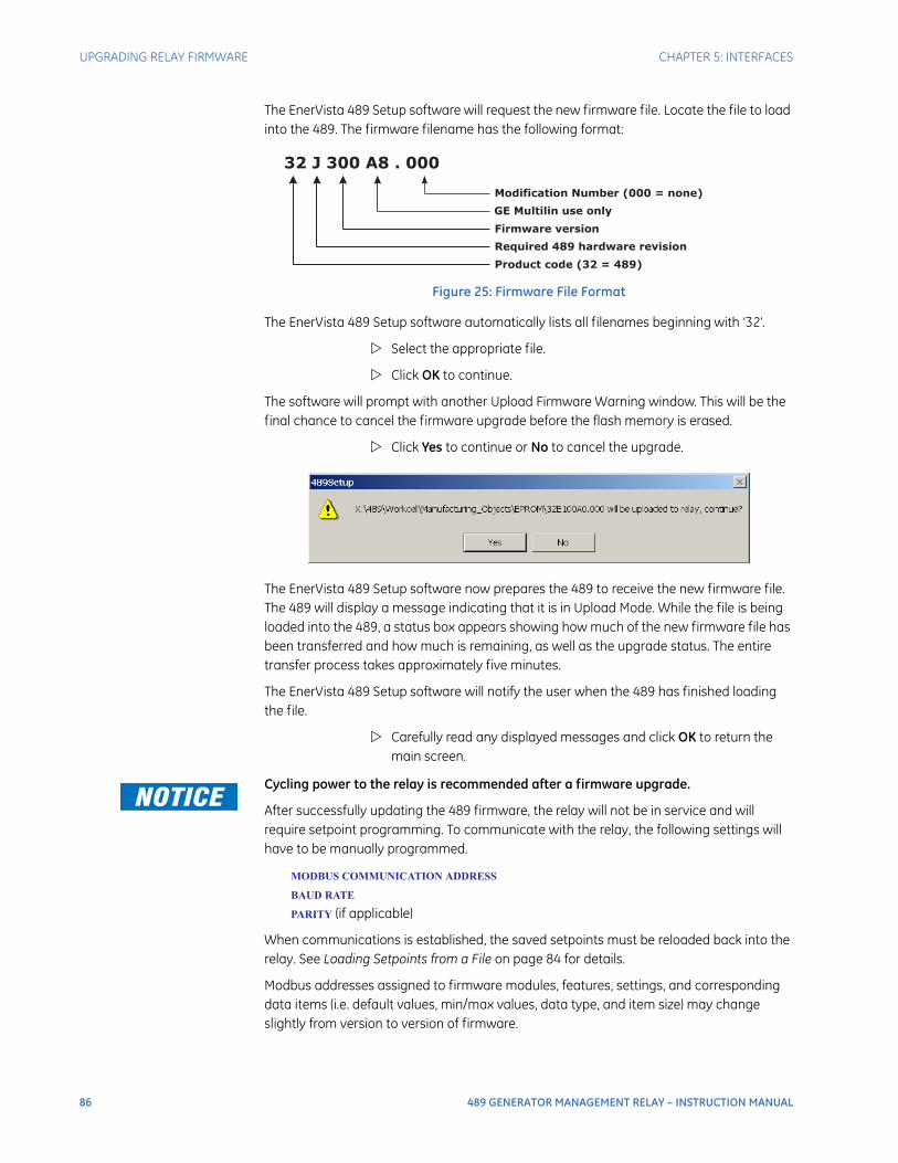
86 489 GENERATOR MANAGEMENT RELAY – INSTRUCTION MANUAL
UPGRADING RELAY FIRMWARE CHAPTER 5: INTERFACES
The EnerVista 489 Setup software will request the new firmware file. Locate the file to load into the 489. The firmware filename has the following format:
Figure 25: Firmware File Format
The EnerVista 489 Setup software automatically lists all filenames beginning with ‘32’.
Select the appropriate file.
Click OK to continue.
The software will prompt with another Upload Firmware Warning window. This will be the final chance to cancel the firmware upgrade before the flash memory is erased.
Click Yes to continue or No to cancel the upgrade.
The EnerVista 489 Setup software now prepares the 489 to receive the new firmware file. The 489 will display a message indicating that it is in Upload Mode. While the file is being loaded into the 489, a status box appears showing how much of the new firmware file has been transferred and how much is remaining, as well as the upgrade status. The entire transfer process takes approximately five minutes.
The EnerVista 489 Setup software will notify the user when the 489 has finished loading the file.
Carefully read any displayed messages and click OK to return the main screen.
Cycling power to the relay is recommended after a firmware upgrade.
After successfully updating the 489 firmware, the relay will not be in service and will require setpoint programming. To communicate with the relay, the following settings will have to be manually programmed.
MODBUS COMMUNICATION ADDRESS
BAUD RATE
PARITY (if applicable)
When communications is established, the saved setpoints must be reloaded back into the relay. See Loading Setpoints from a File on page 84 for details.
Modbus addresses assigned to firmware modules, features, settings, and corresponding data items (i.e. default values, min/max values, data type, and item size) may change slightly from version to version of firmware.
32 J 300 A8 . 000
Modification Number (000 = none)
GE Multilin use only
Firmware version
Required 489 hardware revision
Product code (32 = 489)

CHAPTER 5: INTERFACES ADVANCED ENERVISTA 489 SETUP FEATURES
489 GENERATOR MANAGEMENT RELAY – INSTRUCTION MANUAL 87
The addresses are rearranged when new features are added or existing features are enhanced or modified. The EEPROM DATA ERROR message displayed after upgrading/downgrading the firmware is a resettable, self-test message intended to inform users that the Modbus addresses have changed with the upgraded firmware. This message does not signal any problems when appearing after firmware upgrades.
Advanced EnerVista 489 Setup Features
Triggered EventsWhile the interface is in either on-line or off-line mode, data generated by triggered specified parameters can be viewed and analyzed via one of the following:
• Event Recorder: The event recorder captures contextual data associated with the last 256 events, listed in chronological order from most recent to the oldest.
• Oscillography: The oscillography waveform traces provide a visual display of power system and relay operation data captured during specific triggered events.
Waveform Capture (Trace Memory)The EnerVista 489 Setup software can be used to capture waveforms (or view trace memory) from the 489 relay at the instance of a trip. A maximum of 128 cycles can be captured and the trigger point can be adjusted to anywhere within the set cycles. A maximum of 16 waveforms can be buffered (stored) with the buffer/cycle trade-off.
The following waveforms can be captured:
• Phase A, B, and C currents (Ia, Ib, and Ic)
• Neutral end A, B, and C currents (Ineutral_a, Ineutral_b, and Ineutral_c)
• Ground currents (Ig)
• Phase A-N, B-N, and C-N voltages (Va, Vb, and Vc)
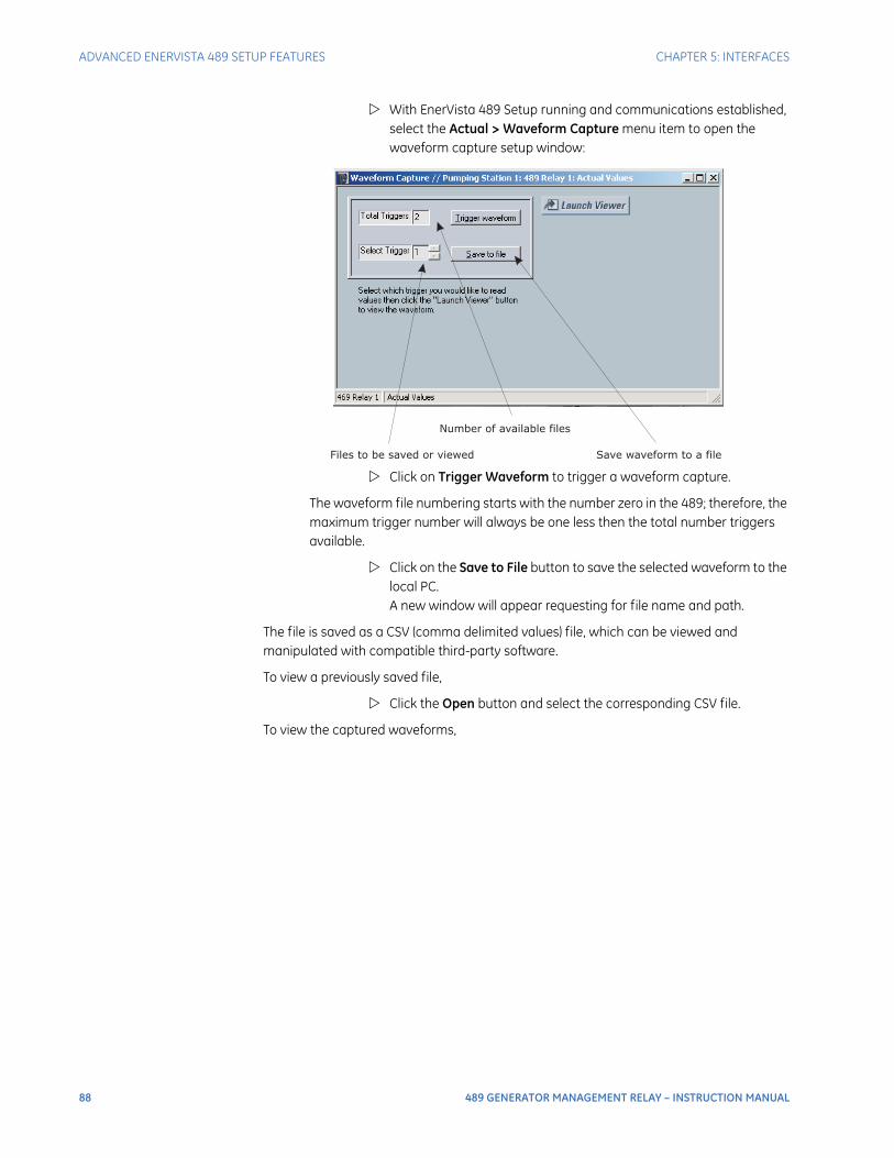
88 489 GENERATOR MANAGEMENT RELAY – INSTRUCTION MANUAL
ADVANCED ENERVISTA 489 SETUP FEATURES CHAPTER 5: INTERFACES
With EnerVista 489 Setup running and communications established, select the Actual > Waveform Capture menu item to open the waveform capture setup window:
Click on Trigger Waveform to trigger a waveform capture.
The waveform file numbering starts with the number zero in the 489; therefore, the maximum trigger number will always be one less then the total number triggers available.
Click on the Save to File button to save the selected waveform to the local PC. A new window will appear requesting for file name and path.
The file is saved as a CSV (comma delimited values) file, which can be viewed and manipulated with compatible third-party software.
To view a previously saved file,
Click the Open button and select the corresponding CSV file.
To view the captured waveforms,
Number of available files
Files to be saved or viewed Save waveform to a file
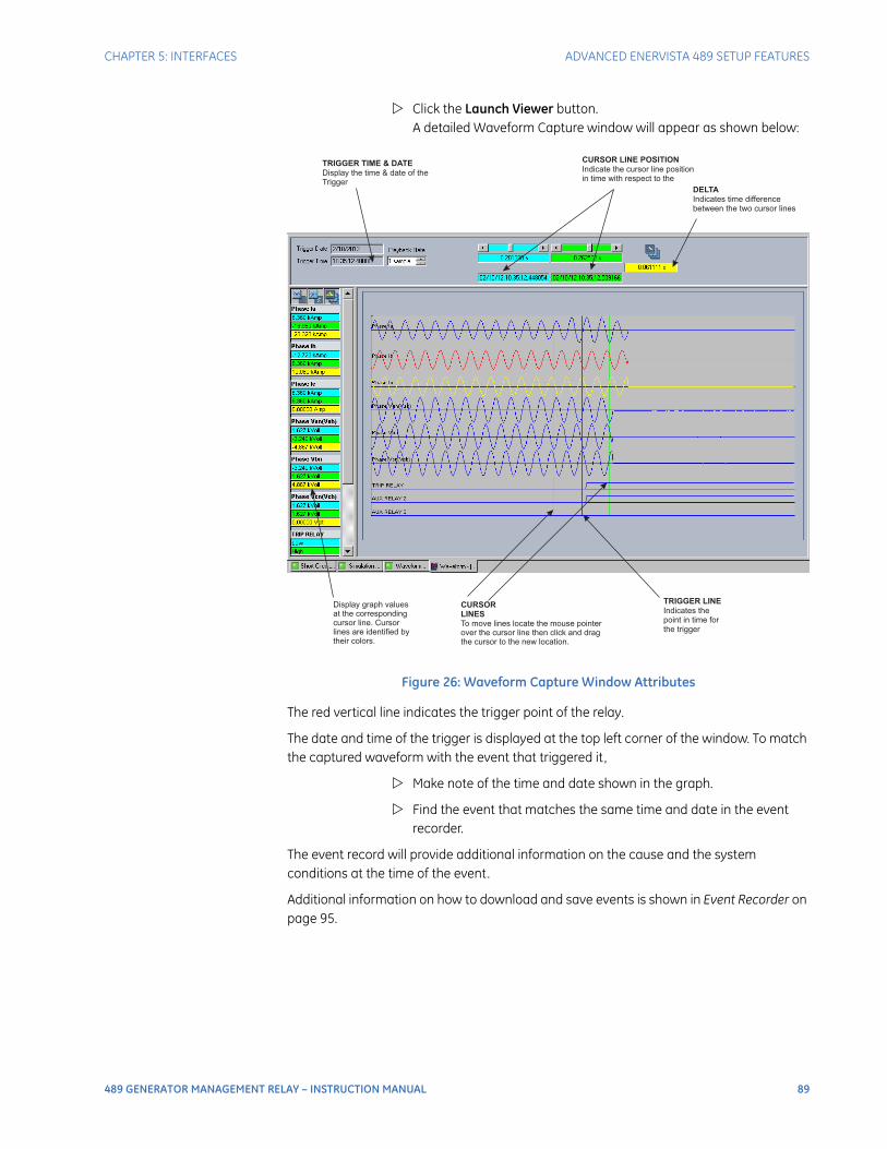
CHAPTER 5: INTERFACES ADVANCED ENERVISTA 489 SETUP FEATURES
489 GENERATOR MANAGEMENT RELAY – INSTRUCTION MANUAL 89
Click the Launch Viewer button. A detailed Waveform Capture window will appear as shown below:
Figure 26: Waveform Capture Window Attributes
The red vertical line indicates the trigger point of the relay.
The date and time of the trigger is displayed at the top left corner of the window. To match the captured waveform with the event that triggered it ,
Make note of the time and date shown in the graph.
Find the event that matches the same time and date in the event recorder.
The event record will provide additional information on the cause and the system conditions at the time of the event.
Additional information on how to download and save events is shown in Event Recorder on page 95.
Display graph valuesat the correspondingcursor line. Cursorlines are identified bytheir colors.
CURSOR
LINES
To move lines locate the mouse pointerover the cursor line then click and dragthe cursor to the new location.
DELTA
Indicates time differencebetween the two cursor lines
TRIGGER LINE
Indicates thepoint in time forthe trigger
TRIGGER TIME & DATE
Display the time & date of theTrigger
CURSOR LINE POSITION
Indicate the cursor line positionin time with respect to the
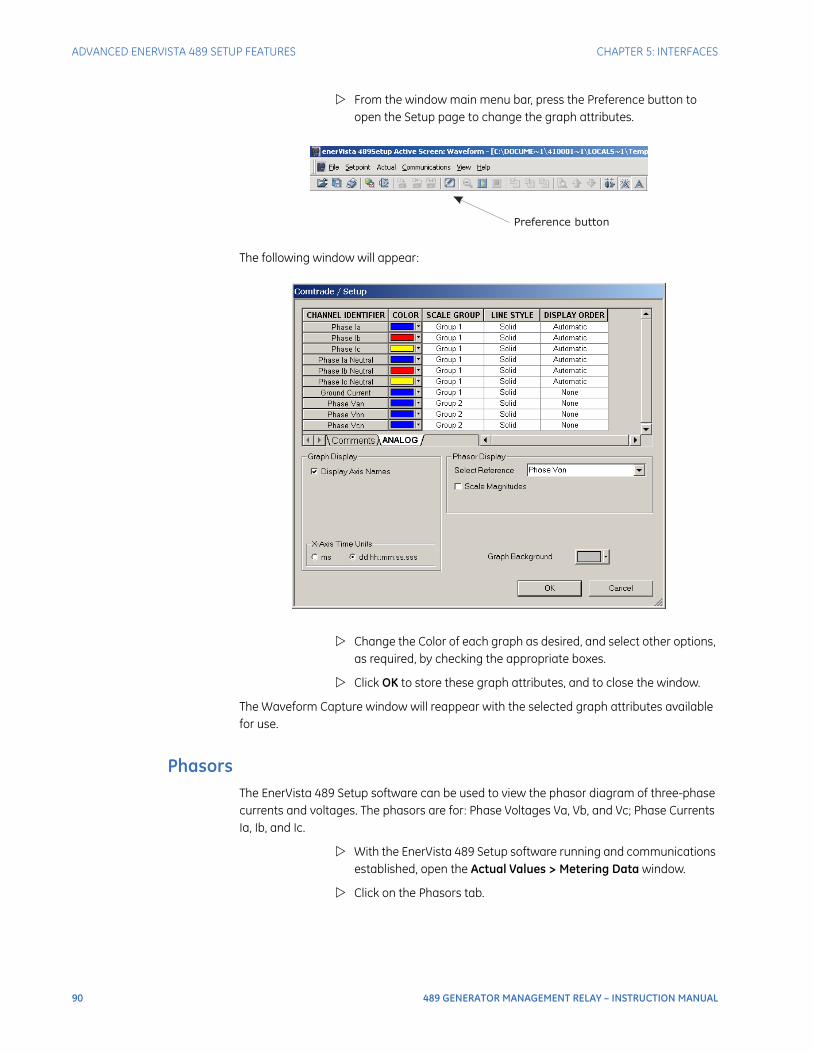
90 489 GENERATOR MANAGEMENT RELAY – INSTRUCTION MANUAL
ADVANCED ENERVISTA 489 SETUP FEATURES CHAPTER 5: INTERFACES
From the window main menu bar, press the Preference button to open the Setup page to change the graph attributes.
The following window will appear:
Change the Color of each graph as desired, and select other options, as required, by checking the appropriate boxes.
Click OK to store these graph attributes, and to close the window.
The Waveform Capture window will reappear with the selected graph attributes available for use.
PhasorsThe EnerVista 489 Setup software can be used to view the phasor diagram of three-phase currents and voltages. The phasors are for: Phase Voltages Va, Vb, and Vc; Phase Currents Ia, Ib, and Ic.
With the EnerVista 489 Setup software running and communications established, open the Actual Values > Metering Data window.
Click on the Phasors tab.
Preference button
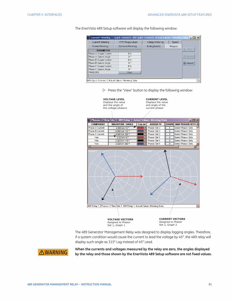
CHAPTER 5: INTERFACES ADVANCED ENERVISTA 489 SETUP FEATURES
489 GENERATOR MANAGEMENT RELAY – INSTRUCTION MANUAL 91
The EnerVista 489 Setup software will display the following window:
Press the “View” button to display the following window:
The 489 Generator Management Relay was designed to display lagging angles. Therefore, if a system condition would cause the current to lead the voltage by 45°, the 489 relay will display such angle as 315° Lag instead of 45° Lead.
When the currents and voltages measured by the relay are zero, the angles displayed by the relay and those shown by the EnerVista 489 Setup software are not fixed values.
VOLTAGE VECTORS
Assigned to Phasor
Set 1, Graph 1
CURRENT VECTORS
Assigned to Phasor
Set 2, Graph 2
CURRENT LEVEL
Displays the value
and angle of the
current phasor
VOLTAGE LEVEL
Displays the value
and the angle of
the voltage phasors

92 489 GENERATOR MANAGEMENT RELAY – INSTRUCTION MANUAL
ADVANCED ENERVISTA 489 SETUP FEATURES CHAPTER 5: INTERFACES
Trending (Data Logger)The trending or data logger feature is used to sample and record up to eight actual values at an interval defined by the user. Several parameters can be trended and graphed at sampling periods ranging from 1 second up to 1 hour. The parameters which can be trended by the EnerVista 489 Setup software are:
• Currents/Voltages:
Phase Currents A, B, and CGenerator LoadNegative-Sequence CurrentGround Current and Neutral CurrentDifferential Currents A, B, and CSystem FrequencyVoltages Vab, Vbc, Vca Van, Vbn & Vcn
• Power:
Power FactorReal (kW) Reactive (kvar), and Apparent (kVA) PowerPositive WatthoursPositive and Negative Varhours
• Temperature:
Hottest Stator RTDThermal Capacity UsedRTDs 1 through 12
• Demand:
CurrentPeak CurrentReactive PowerPeak Reactive PowerApparent PowerPeak Apparent Power
• Others:
Analog Inputs 1, 2, 3, and 4Tachometer
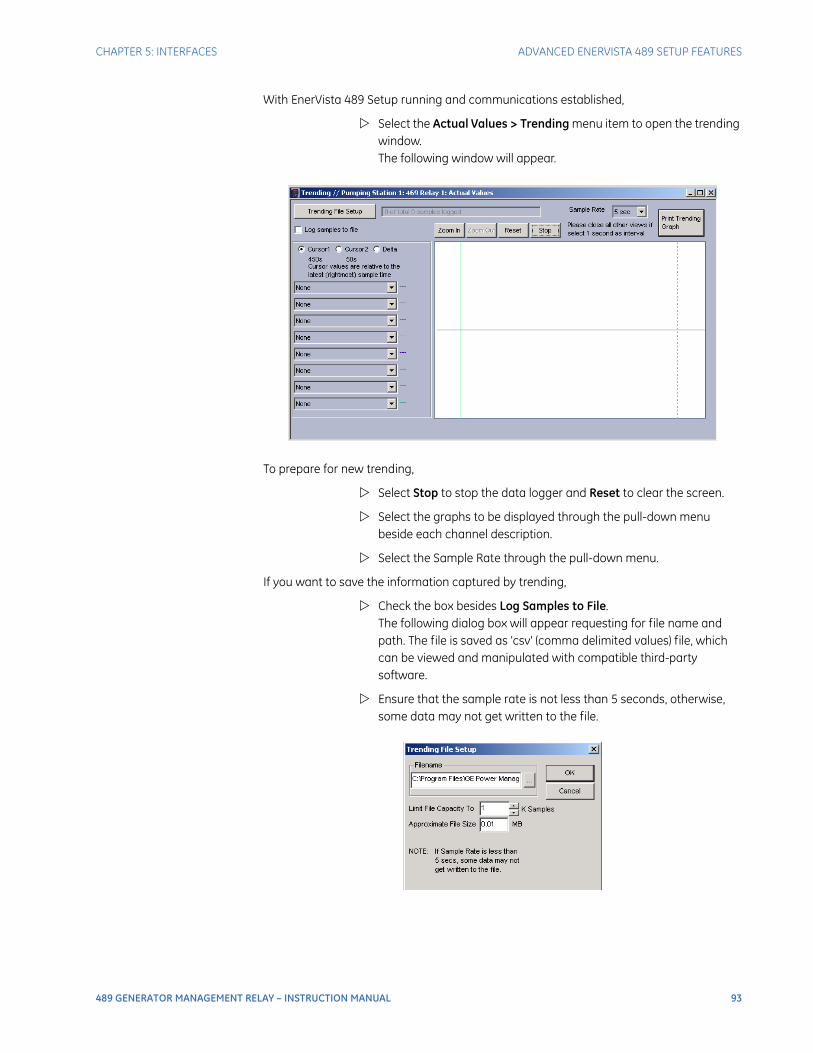
CHAPTER 5: INTERFACES ADVANCED ENERVISTA 489 SETUP FEATURES
489 GENERATOR MANAGEMENT RELAY – INSTRUCTION MANUAL 93
With EnerVista 489 Setup running and communications established,
Select the Actual Values > Trending menu item to open the trending window. The following window will appear.
To prepare for new trending,
Select Stop to stop the data logger and Reset to clear the screen.
Select the graphs to be displayed through the pull-down menu beside each channel description.
Select the Sample Rate through the pull-down menu.
If you want to save the information captured by trending,
Check the box besides Log Samples to File. The following dialog box will appear requesting for file name and path. The file is saved as 'csv' (comma delimited values) file, which can be viewed and manipulated with compatible third-party software.
Ensure that the sample rate is not less than 5 seconds, otherwise, some data may not get written to the file.
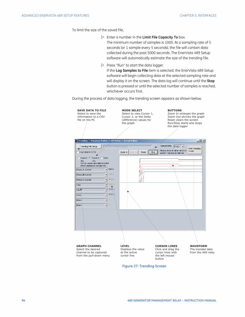
94 489 GENERATOR MANAGEMENT RELAY – INSTRUCTION MANUAL
ADVANCED ENERVISTA 489 SETUP FEATURES CHAPTER 5: INTERFACES
To limit the size of the saved file,
Enter a number in the Limit File Capacity To box. The minimum number of samples is 1000. At a sampling rate of 5 seconds (or 1 sample every 5 seconds), the file will contain data collected during the past 5000 seconds. The EnerVista 489 Setup software will automatically estimate the size of the trending file.
Press “Run” to start the data logger.If the Log Samples to File item is selected, the EnerVista 489 Setup software will begin collecting data at the selected sampling rate and will display it on the screen. The data log will continue until the Stop button is pressed or until the selected number of samples is reached, whichever occurs first.
During the process of data logging, the trending screen appears as shown below.
Figure 27: Trending Screen
SAVE DATA TO FILE
Select to save the
information to a CSV
file on the PC
MODE SELECT
Select to view Cursor 1,
Cursor 2, or the Delta
(difference) values for
the graph
BUTTONS
Zoom In enlarges the graph
Zoom Out shrinks the graph
Reset clears the screen
Run/Stop starts and stops
the data logger
GRAPH CHANNEL
Select the desired
channel to be captured
from the pull-down menu
LEVEL
Displays the value
at the active
cursor line
WAVEFORM
The trended data
from the 469 relay
CURSOR LINES
Click and drag the
cursor lines with
the left mouse
button
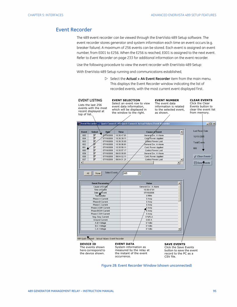
CHAPTER 5: INTERFACES ADVANCED ENERVISTA 489 SETUP FEATURES
489 GENERATOR MANAGEMENT RELAY – INSTRUCTION MANUAL 95
Event RecorderThe 489 event recorder can be viewed through the EnerVista 489 Setup software. The event recorder stores generator and system information each time an event occurs (e.g. breaker failure). A maximum of 256 events can be stored. Each event is assigned an event number, from E001 to E256. When the E256 is reached, E001 is assigned to the next event. Refer to Event Recorder on page 233 for additional information on the event recorder.
Use the following procedure to view the event recorder with EnerVista 489 Setup:
With EnerVista 489 Setup running and communications established,
Select the Actual > A4 Event Recorder item from the main menu. This displays the Event Recorder window indicating the list of recorded events, with the most current event displayed first.
Figure 28: Event Recorder Window (shown unconnected)
EVENT LISTINGLists the last 256 events with the most recent displayed at top of list.
EVENT SELECTIONSelect an event row to view event data information, which will be displayed in the window to the right.
EVENT NUMBERThe event data information is related to the selected event, as shown.
CLEAR EVENTSClick the Clear Events button to clear the event list from memory.
DEVICE IDThe events shown here correspond to the device shown.
EVENT DATASystem information as measured by the relay at the instant of the event occurrence.
SAVE EVENTSClick the Save Events button to save the event record to the PC as a CSV file.

96 489 GENERATOR MANAGEMENT RELAY – INSTRUCTION MANUAL
ADVANCED ENERVISTA 489 SETUP FEATURES CHAPTER 5: INTERFACES
To view detailed information for a given event and the system information at the moment of the event occurrence,
Change the event number on the Select Event box.
Modbus User MapThe EnerVista 489 Setup software provides a means to program the 489 User Map (Modbus addresses 0180h to 01F7h). Refer to GE Publication GEK-106491: 489 Communications Guide for additional information on the User Map.
Select a connected device in EnerVista 489 Setup.
Select the Setpoint > User Map menu item to open the following window.
This window allows the desired addresses to be written to User Map locations. The User Map values that correspond to these addresses are then displayed.
Viewing Actual ValuesYou can view real-time relay data such as input/output status and measured parameters. From the main window menu bar, selecting Actual Values opens a window with tabs, each tab containing data in accordance with the following list:

CHAPTER 5: INTERFACES ADVANCED ENERVISTA 489 SETUP FEATURES
489 GENERATOR MANAGEMENT RELAY – INSTRUCTION MANUAL 97
1. Generator and System Status:
• Generator status either stopped, starting, or running. It includes values such as generator load, thermal capacity used, generator speed, and instantaneous values of power system quantities.
• The status of digital inputs.
• Last trip information, including values such as cause of last trip, time and date of trip, generator speed and load at the time of trip, pre-trip temperature measurements, pre-trip analog inputs values, and pre-trip instantaneous values of power system quantities.
• Active alarms.
• Relay date and time.
• Present blocking conditions.
• General system status indication including the status of output relays, active pickup, alarm and trip conditions.
2. Metering Data:
• Instantaneous current measurements including phase, differential, unbalance, ground, average, generator load, and differential currents.
• RTD Temperatures including hottest RTDs.
• Instantaneous phase to phase and phase to ground voltages (depending on the VT connections), average voltage, and system frequency.
• Generator Speed
• Power Quantities including Apparent, Real and Reactive Power.
• Current and power demand including peak values.
• Analog inputs
• Vector information.
3. Generator Learned Data:
• Average Generator Load
• Average Negative-Sequence Current
• Phase-Phase Voltage
• RTD Maximum Values
4. Maintenance data. This is useful statistical information that may be used for preventive maintenance. It includes:
• Trip counters
• General counter such as Number of Breaker Operations.
• Timers such as Generator Running Hours.
5. RTD Learned Data - includes the maximum temperature measured by each of the 12 RTDs.
6. Event recorder downloading tool.
7. Product information including model number, firmware version, additional product information, and calibration dates.
8. Oscillography and Data Logger downloading tool.
Selecting an actual values window also opens the actual values tree from the corresponding device in the site list and highlights the current location in the hierarchy.
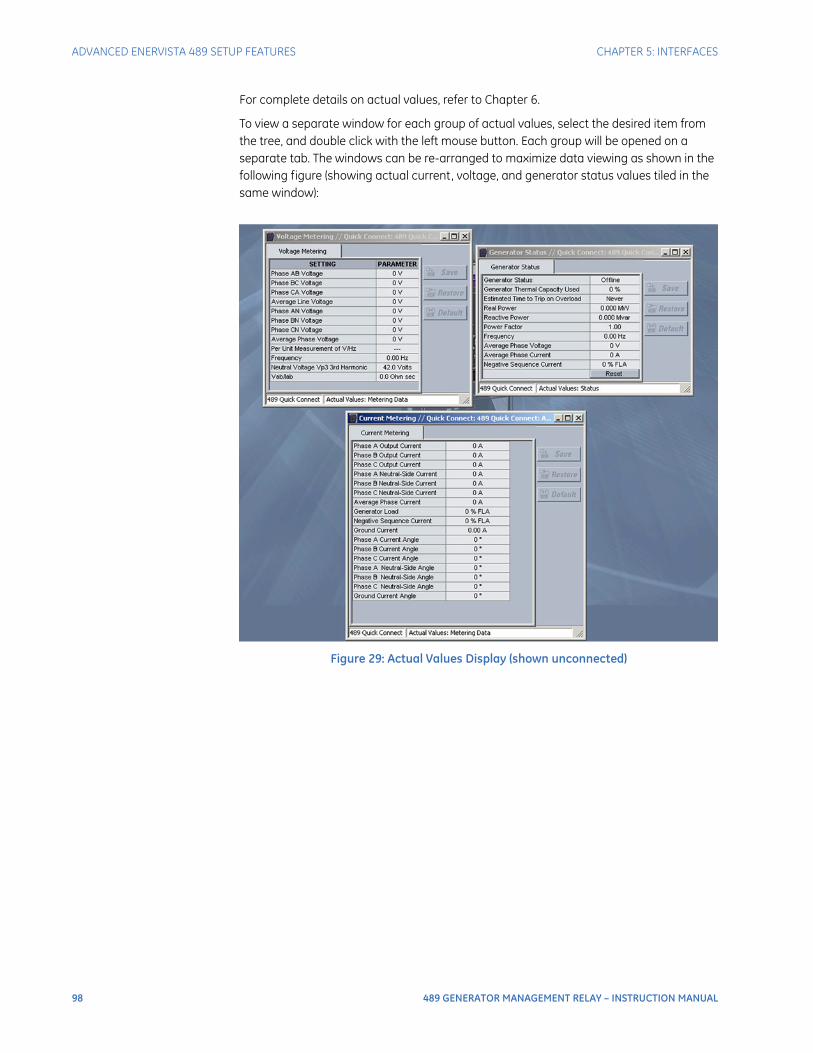
98 489 GENERATOR MANAGEMENT RELAY – INSTRUCTION MANUAL
ADVANCED ENERVISTA 489 SETUP FEATURES CHAPTER 5: INTERFACES
For complete details on actual values, refer to Chapter 6.
To view a separate window for each group of actual values, select the desired item from the tree, and double click with the left mouse button. Each group will be opened on a separate tab. The windows can be re-arranged to maximize data viewing as shown in the following figure (showing actual current, voltage, and generator status values tiled in the same window):
Figure 29: Actual Values Display (shown unconnected)
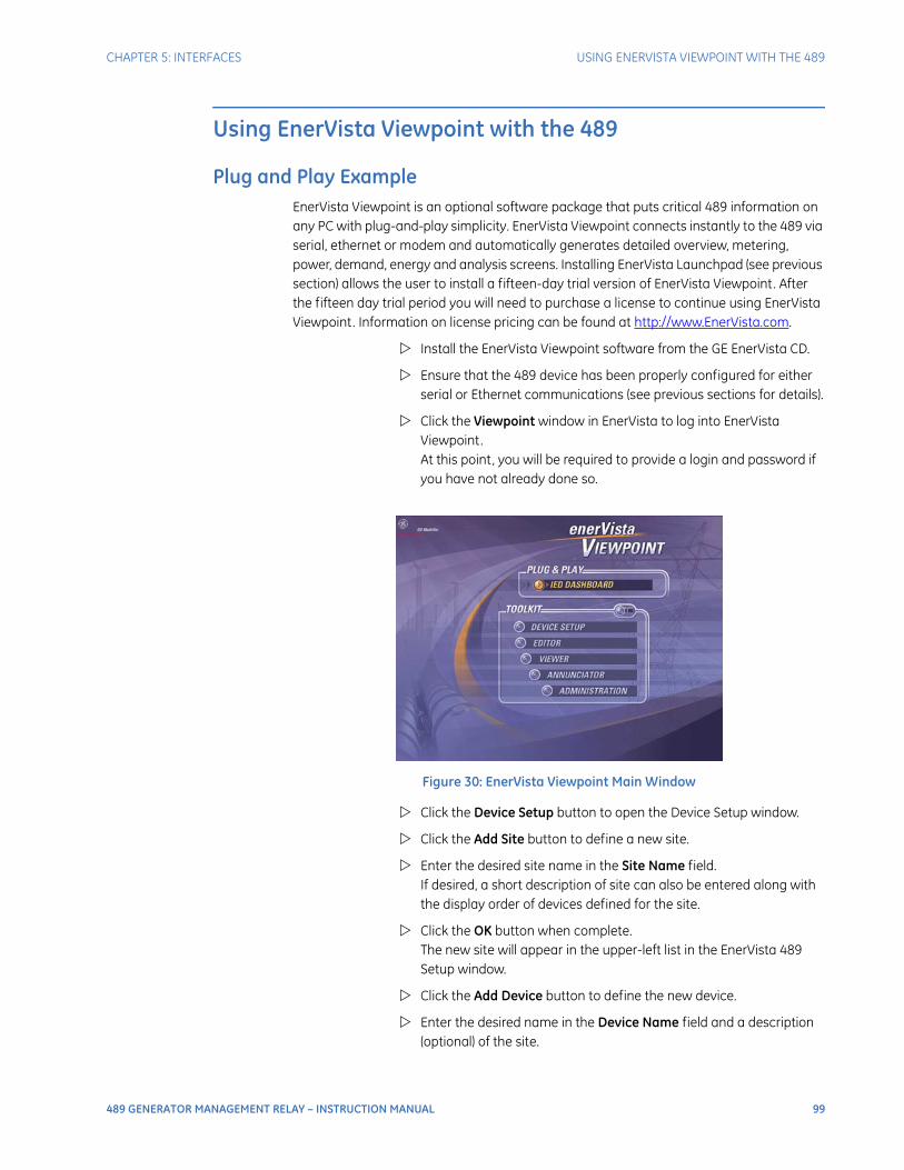
CHAPTER 5: INTERFACES USING ENERVISTA VIEWPOINT WITH THE 489
489 GENERATOR MANAGEMENT RELAY – INSTRUCTION MANUAL 99
Using EnerVista Viewpoint with the 489
Plug and Play ExampleEnerVista Viewpoint is an optional software package that puts critical 489 information on any PC with plug-and-play simplicity. EnerVista Viewpoint connects instantly to the 489 via serial, ethernet or modem and automatically generates detailed overview, metering, power, demand, energy and analysis screens. Installing EnerVista Launchpad (see previous section) allows the user to install a fifteen-day trial version of EnerVista Viewpoint. After the fifteen day trial period you will need to purchase a license to continue using EnerVista Viewpoint. Information on license pricing can be found at http://www.EnerVista.com.
Install the EnerVista Viewpoint software from the GE EnerVista CD.
Ensure that the 489 device has been properly configured for either serial or Ethernet communications (see previous sections for details).
Click the Viewpoint window in EnerVista to log into EnerVista Viewpoint. At this point, you will be required to provide a login and password if you have not already done so.
Figure 30: EnerVista Viewpoint Main Window
Click the Device Setup button to open the Device Setup window.
Click the Add Site button to define a new site.
Enter the desired site name in the Site Name field. If desired, a short description of site can also be entered along with the display order of devices defined for the site.
Click the OK button when complete. The new site will appear in the upper-left list in the EnerVista 489 Setup window.
Click the Add Device button to define the new device.
Enter the desired name in the Device Name field and a description (optional) of the site.
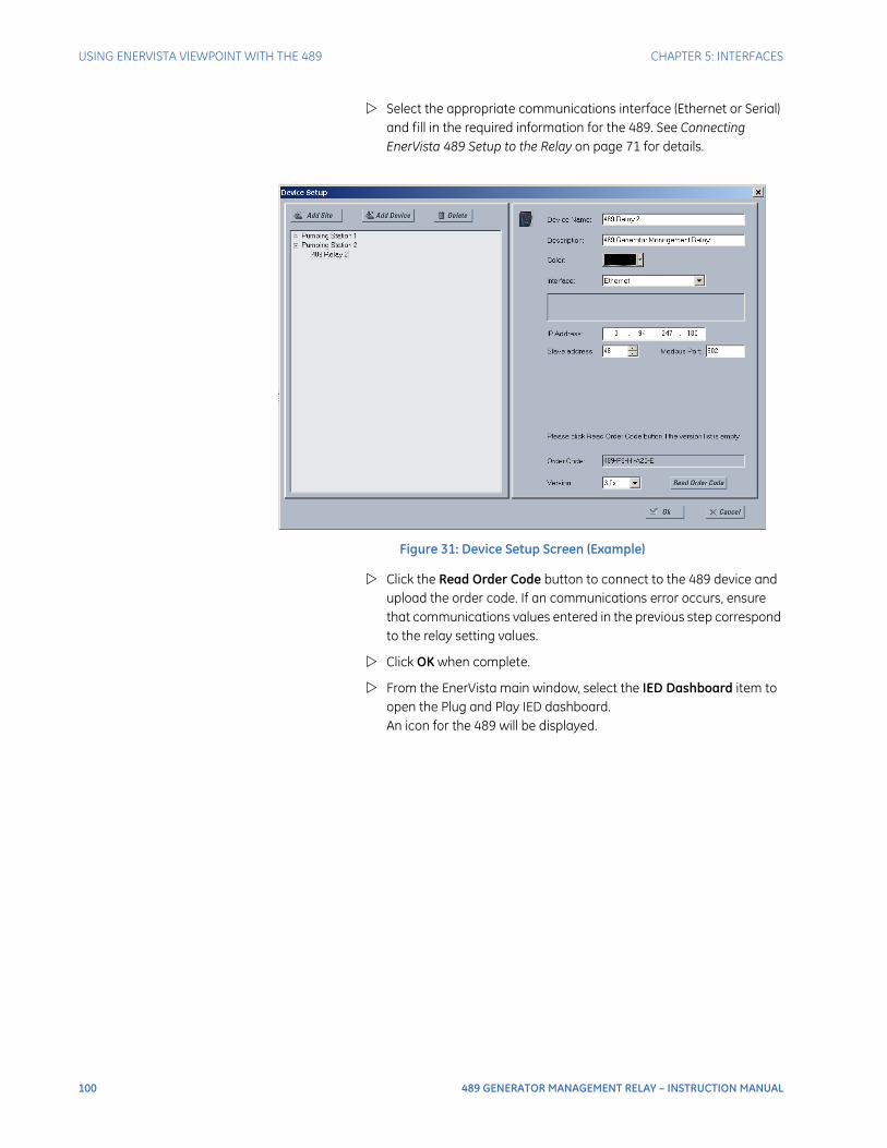
100 489 GENERATOR MANAGEMENT RELAY – INSTRUCTION MANUAL
USING ENERVISTA VIEWPOINT WITH THE 489 CHAPTER 5: INTERFACES
Select the appropriate communications interface (Ethernet or Serial) and fill in the required information for the 489. See Connecting EnerVista 489 Setup to the Relay on page 71 for details.
Figure 31: Device Setup Screen (Example)
Click the Read Order Code button to connect to the 489 device and upload the order code. If an communications error occurs, ensure that communications values entered in the previous step correspond to the relay setting values.
Click OK when complete.
From the EnerVista main window, select the IED Dashboard item to open the Plug and Play IED dashboard. An icon for the 489 will be displayed.

CHAPTER 5: INTERFACES USING ENERVISTA VIEWPOINT WITH THE 489
489 GENERATOR MANAGEMENT RELAY – INSTRUCTION MANUAL 101
Figure 32: ‘Plug and Play’ Dashboard
Click the Dashboard button below the 489 icon to view the device information.
We have now successfully accessed our 489 through EnerVista Viewpoint.
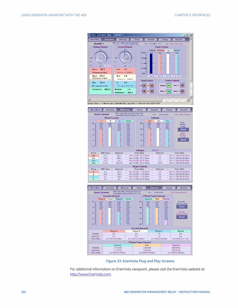
102 489 GENERATOR MANAGEMENT RELAY – INSTRUCTION MANUAL
USING ENERVISTA VIEWPOINT WITH THE 489 CHAPTER 5: INTERFACES
Figure 33: EnerVista Plug and Play Screens
For additional information on EnerVista viewpoint, please visit the EnerVista website at http://www.EnerVista.com.
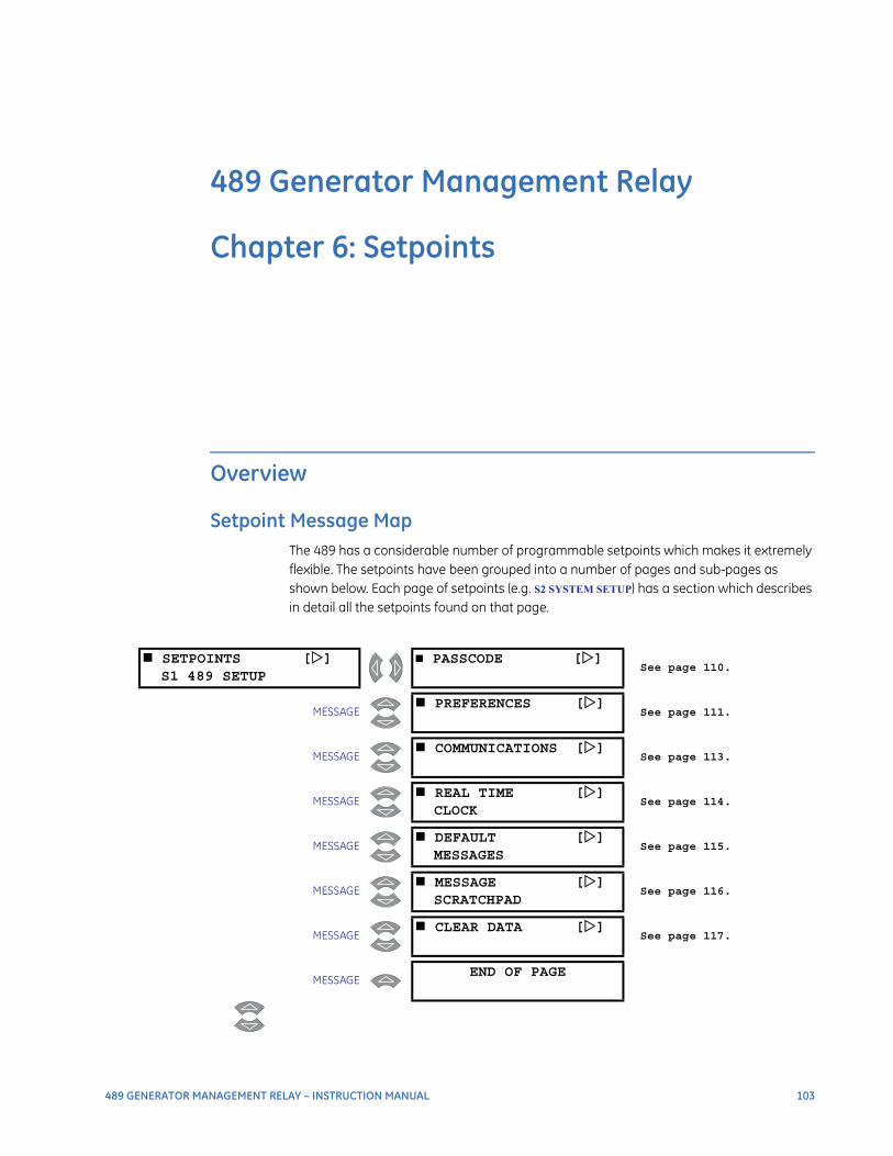
489 GENERATOR MANAGEMENT RELAY – INSTRUCTION MANUAL 103
489 Generator Management Relay
Chapter 6: Setpoints
Setpoints
Overview
Setpoint Message MapThe 489 has a considerable number of programmable setpoints which makes it extremely flexible. The setpoints have been grouped into a number of pages and sub-pages as shown below. Each page of setpoints (e.g. S2 SYSTEM SETUP) has a section which describes in detail all the setpoints found on that page.
SETPOINTS []S1 489 SETUP
PASSCODE []See page 110.
MESSAGE PREFERENCES []
See page 111.
MESSAGE COMMUNICATIONS []
See page 113.
MESSAGE REAL TIME []
CLOCKSee page 114.
MESSAGE DEFAULT []
MESSAGESSee page 115.
MESSAGE MESSAGE []
SCRATCHPADSee page 116.
MESSAGE CLEAR DATA []
See page 117.
MESSAGEEND OF PAGE

104 489 GENERATOR MANAGEMENT RELAY – INSTRUCTION MANUAL
OVERVIEW CHAPTER 6: SETPOINTS
SETPOINTS []S2 SYSTEM SETUP
CURRENT []SENSING
See page 119.
MESSAGE VOLTAGE []
SENSINGSee page 119.
MESSAGE GENERATOR []
PARAMETERSSee page 120.
MESSAGE SERIAL []
STOP/STARTSee page 121.
MESSAGEEND OF PAGE
SETPOINTS []S3 DIGITAL INPUTS
BREAKER []STATUS
See page 122.
MESSAGE GENERAL []
INPUT ASee page 123.
MESSAGE GENERAL []
INPUT BSee page 123.
↓
MESSAGE GENERAL []
INPUT GSee page 123.
MESSAGE REMOTE RESET []
See page 124.
MESSAGE TEST INPUT []
See page 124.
MESSAGE THERMAL RESET []
See page 124.
MESSAGE DUAL []
SETPOINTSSee page 125.
MESSAGE SEQUENTIAL []
TRIPSee page 126.
MESSAGE FIELD-BREAKER []
DISCREPANCYSee page 127.
MESSAGE TACHOMETER []
See page 127.
MESSAGE WAVEFORM []
CAPTURESee page 128.
MESSAGE GROUND []
SWITCH STATUSSee page 128.
MESSAGEEND OF PAGE
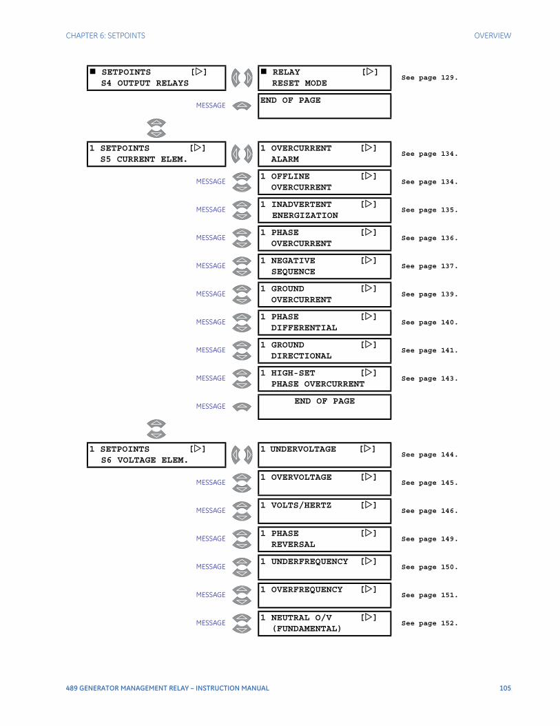
CHAPTER 6: SETPOINTS OVERVIEW
489 GENERATOR MANAGEMENT RELAY – INSTRUCTION MANUAL 105
SETPOINTS []S4 OUTPUT RELAYS
RELAY []RESET MODE
See page 129.
MESSAGEEND OF PAGE
1 SETPOINTS []S5 CURRENT ELEM.
1 OVERCURRENT []ALARM
See page 134.
MESSAGE1 OFFLINE []
OVERCURRENTSee page 134.
MESSAGE1 INADVERTENT []
ENERGIZATIONSee page 135.
MESSAGE1 PHASE []
OVERCURRENTSee page 136.
MESSAGE1 NEGATIVE []
SEQUENCESee page 137.
MESSAGE1 GROUND []
OVERCURRENTSee page 139.
MESSAGE1 PHASE []
DIFFERENTIALSee page 140.
MESSAGE1 GROUND []
DIRECTIONALSee page 141.
MESSAGE1 HIGH-SET []
PHASE OVERCURRENTSee page 143.
MESSAGEEND OF PAGE
1 SETPOINTS []S6 VOLTAGE ELEM.
1 UNDERVOLTAGE []See page 144.
MESSAGE1 OVERVOLTAGE []
See page 145.
MESSAGE1 VOLTS/HERTZ []
See page 146.
MESSAGE1 PHASE []
REVERSALSee page 149.
MESSAGE1 UNDERFREQUENCY []
See page 150.
MESSAGE1 OVERFREQUENCY []
See page 151.
MESSAGE1 NEUTRAL O/V []
(FUNDAMENTAL)See page 152.
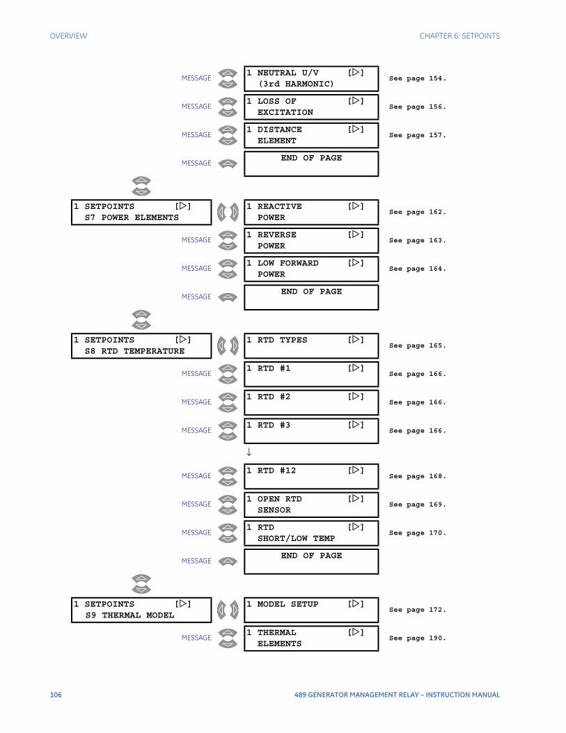
106 489 GENERATOR MANAGEMENT RELAY – INSTRUCTION MANUAL
OVERVIEW CHAPTER 6: SETPOINTS
MESSAGE1 NEUTRAL U/V []
(3rd HARMONIC)See page 154.
MESSAGE1 LOSS OF []
EXCITATIONSee page 156.
MESSAGE1 DISTANCE []
ELEMENTSee page 157.
MESSAGEEND OF PAGE
1 SETPOINTS []S7 POWER ELEMENTS
1 REACTIVE []POWER
See page 162.
MESSAGE1 REVERSE []
POWERSee page 163.
MESSAGE1 LOW FORWARD []
POWERSee page 164.
MESSAGEEND OF PAGE
1 SETPOINTS []S8 RTD TEMPERATURE
1 RTD TYPES []See page 165.
MESSAGE1 RTD #1 []
See page 166.
MESSAGE1 RTD #2 []
See page 166.
MESSAGE1 RTD #3 []
See page 166.
↓
MESSAGE1 RTD #12 []
See page 168.
MESSAGE1 OPEN RTD []
SENSORSee page 169.
MESSAGE1 RTD []
SHORT/LOW TEMPSee page 170.
MESSAGEEND OF PAGE
1 SETPOINTS []S9 THERMAL MODEL
1 MODEL SETUP []See page 172.
MESSAGE1 THERMAL []
ELEMENTSSee page 190.
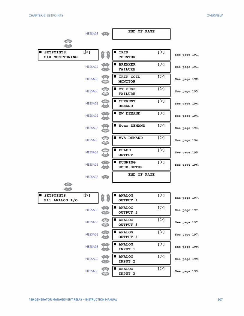
CHAPTER 6: SETPOINTS OVERVIEW
489 GENERATOR MANAGEMENT RELAY – INSTRUCTION MANUAL 107
MESSAGEEND OF PAGE
SETPOINTS []S10 MONITORING
TRIP []COUNTER
See page 191.
MESSAGE BREAKER []
FAILURESee page 191.
MESSAGE TRIP COIL []
MONITORSee page 192.
MESSAGE VT FUSE []
FAILURESee page 193.
MESSAGE CURRENT []
DEMANDSee page 194.
MESSAGE MW DEMAND []
See page 194.
MESSAGE Mvar DEMAND []
See page 194.
MESSAGE MVA DEMAND []
See page 194.
MESSAGE PULSE []
OUTPUTSee page 195.
MESSAGE RUNNING []
HOUR SETUPSee page 196.
MESSAGEEND OF PAGE
SETPOINTS []S11 ANALOG I/O
ANALOG []OUTPUT 1
See page 197.
MESSAGE ANALOG []
OUTPUT 2See page 197.
MESSAGE ANALOG []
OUTPUT 3See page 197.
MESSAGE ANALOG []
OUTPUT 4See page 197.
MESSAGE ANALOG []
INPUT 1See page 199.
MESSAGE ANALOG []
INPUT 2See page 199.
MESSAGE ANALOG []
INPUT 3See page 199.
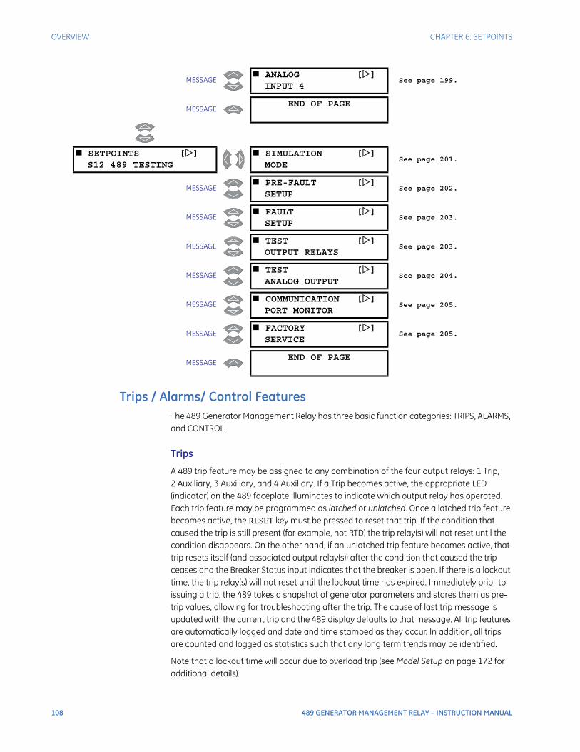
108 489 GENERATOR MANAGEMENT RELAY – INSTRUCTION MANUAL
OVERVIEW CHAPTER 6: SETPOINTS
Trips / Alarms/ Control FeaturesThe 489 Generator Management Relay has three basic function categories: TRIPS, ALARMS, and CONTROL.
Trips
A 489 trip feature may be assigned to any combination of the four output relays: 1 Trip, 2 Auxiliary, 3 Auxiliary, and 4 Auxiliary. If a Trip becomes active, the appropriate LED (indicator) on the 489 faceplate illuminates to indicate which output relay has operated. Each trip feature may be programmed as latched or unlatched. Once a latched trip feature becomes active, the RESET key must be pressed to reset that trip. If the condition that caused the trip is still present (for example, hot RTD) the trip relay(s) will not reset until the condition disappears. On the other hand, if an unlatched trip feature becomes active, that trip resets itself (and associated output relay(s)) after the condition that caused the trip ceases and the Breaker Status input indicates that the breaker is open. If there is a lockout time, the trip relay(s) will not reset until the lockout time has expired. Immediately prior to issuing a trip, the 489 takes a snapshot of generator parameters and stores them as pre-trip values, allowing for troubleshooting after the trip. The cause of last trip message is updated with the current trip and the 489 display defaults to that message. All trip features are automatically logged and date and time stamped as they occur. In addition, all trips are counted and logged as statistics such that any long term trends may be identified.
Note that a lockout time will occur due to overload trip (see Model Setup on page 172 for additional details).
MESSAGE ANALOG []
INPUT 4See page 199.
MESSAGEEND OF PAGE
SETPOINTS []S12 489 TESTING
SIMULATION []MODE
See page 201.
MESSAGE PRE-FAULT []
SETUPSee page 202.
MESSAGE FAULT []
SETUPSee page 203.
MESSAGE TEST []
OUTPUT RELAYSSee page 203.
MESSAGE TEST []
ANALOG OUTPUTSee page 204.
MESSAGE COMMUNICATION []
PORT MONITORSee page 205.
MESSAGE FACTORY []
SERVICESee page 205.
MESSAGEEND OF PAGE

CHAPTER 6: SETPOINTS OVERVIEW
489 GENERATOR MANAGEMENT RELAY – INSTRUCTION MANUAL 109
Alarms
A 489 alarm feature may be assigned to operate any combination of four output relays: 2 Auxiliary, 3 Auxiliary, 4 Auxiliary, and 5 Alarm. When an alarm becomes active, the appropriate LED (indicator) on the 489 faceplate will illuminate when an output relay(s) has operated. Each alarm feature may be programmed as latched or unlatched. Once a latched alarm feature becomes active, the reset key must be pressed to reset that alarm. If the condition that has caused the alarm is still present (for example, hot RTD) the Alarm relay(s) will not reset until the condition is no longer present. If on the other hand, an unlatched alarm feature becomes active, that alarm will reset itself (and associated output relay(s)) as soon as the condition that caused the alarm ceases. As soon as an alarm occurs, the alarms messages are updated to reflect the alarm and the 489 display defaults to that message. Since it may not be desirable to log all alarms as events, each alarm feature may be programmed to log as an event or not. If an alarm is programmed to log as an event, when it becomes active, it is automatically logged as a date and time stamped event.
Control
A 489 control feature may be assigned to operate any combination of five output relays: 1 Trip, 2 Auxiliary, 3 Auxiliary, 4 Auxiliary, and 5 Alarm. The combination of relays available for each function is determined by the suitability of each relay for that particular function. The appropriate LED (indicator) on the 489 faceplate will illuminate when an output relay(s) has been operated by a control function. Since it may not be desirable to log all control function as events, each control feature may be programmed to log as an event or not. If a control feature is programmed to log as an event, each control relay event is automatically logged with a date and time stamp.
Relay Assignment PracticesThere are six output relays. Five of the relays are always non-failsafe, the other (Service) is failsafe and dedicated to annunciate internal 489 faults (these faults include setpoint corruption, failed hardware components, loss of control power, etc.). The five remaining relays may be programmed for different types of features depending on what is required. One of the relays, 1 Trip, is intended to be used as a trip relay wired to the unit trip breaker. Another relay, 5 Alarm, is intended to be used as the main alarm relay. The three remaining relays, 2 Auxiliary, 3 Auxiliary, and 4 Auxiliary, are intended for special requirements.
When assigning features to relays 2, 3, and 4, it is a good idea to decide early on what is required since features that may be assigned may conflict. For example, if relay 2 is to be dedicated as a relay for sequential tripping, it cannot also be used to annunciate a specific alarm condition.
In order to ensure that conflicts in relay assignments do not occur, several precautions have been taken. All trips default to the 1 Trip output relay and all alarms default to the 5 Alarm relay. It is recommended that relay assignments be reviewed once all the setpoints have been programmed.

110 489 GENERATOR MANAGEMENT RELAY – INSTRUCTION MANUAL
S1 489 SETUP CHAPTER 6: SETPOINTS
Dual SetpointsThe 489 has dual settings for the current, voltage, power, RTD, and thermal model protection elements (setpoints pages S5 to S9). These setpoints are organized in two groups: the main group (Group 1) and the alternate group (Group 2). Only one group of settings is active in the protection scheme at a time. The active group can be selected using the ACTIVATE SETPOINT GROUP setpoint or an assigned digital input in the S3 Digital Inputs setpoints page. The LED indicator on the faceplate of the 489 will indicate when the alternate setpoints are active in the protection scheme. Independently, the setpoints in either group can be viewed and/or edited using the EDIT SETPOINT GROUP setpoint. Headers for each setpoint message subgroup that has dual settings will be denoted by a superscript number indicating which setpoint group is being viewed or edited. Also, when a setpoint that has dual settings is stored, the flash message that appears will indicate which setpoint group setting has been changed.
If only one setting group is required, edit and activate only Group 1 (that is, do not assign a digital input to Dual Setpoints, and do not alter the ACTIVATE SETPOINT GROUP setpoint or EDIT SETPOINT GROUP setpoint in S3 DIGITAL INPUTS).
Commissioning
Tables for recording of 489 programmed setpoints are available as a Microsoft Word document from the GE Multilin website at http://www.GEmultilin.com. See the Support Documents section of the 489 Generator Management Relay page for the latest version. This document is also available in print from the GE Multilin literature department (request publication number GET-8445).
S1 489 Setup
PasscodePATH: SETPOINTS S1 489 SETUP PASSCODE
A passcode access security feature is provided with the 489. The passcode is defaulted to “0” (without the quotes) at the time of shipping. Passcode protection is ignored when the passcode is “0”. In this case, the setpoint access jumper is the only protection when programming setpoints from the front panel keypad and setpoints may be altered using the RS232 and RS485 serial ports without access protection. If however, the passcode is changed to a non-zero value, passcode protection is enabled. The access jumper must be
PASSCODE [] ENTER PASSCODE FORACCESS:
Range: 1 to 8 numeric digits
MESSAGESETPOINT ACCESS:Permitted
Range: Permitted, Restricted
MESSAGECHANGE PASSCODE:No
Range: No, Yes

CHAPTER 6: SETPOINTS S1 489 SETUP
489 GENERATOR MANAGEMENT RELAY – INSTRUCTION MANUAL 111
installed and the passcode must be entered, to program setpoints from the front panel keypad. The passcode must also be entered individually from each serial communications port to gain setpoint programming access from that port.
The ENTER PASSCODE FOR ACCESS setpoint is seen only if the passcode is not 0 and SETPOINT ACCESS is “Restricted”. The SETPOINT ACCESS and CHANGE PASSWORD setpoints are seen only if the passcode is 0 and the SETPOINT ACCESS is “Permitted”.
To enable passcode protection on a new relay, follow the procedure below:
Press ENTER then MESSAGE DOWN until CHANGE PASSCODE message is displayed.
Select Yes and follow directions to enter a new passcode 1 to 8 digits in length.
Once a new passcode (other than “0”) is programmed, it must be entered to gain setpoint access whenever setpoint access is restricted. Assuming that a non-zero passcode has been programmed and setpoint access is restricted, then selecting the passcode subgroup causes the ENTER PASSCODE AGAIN message to appear.
Enter the correct passcode. A flash message will advise if the code is incorrect and allow a retry. If it is correct and the setpoint access jumper is installed, the SETPOINT ACCESS: Permitted message appears.
Setpoints can now be entered.
Exit the passcode message with the ESCAPE key and program the appropriate setpoints. If no keypress occurs for 30 minutes, access will be disabled and the passcode must be re-entered. Removing the setpoint access jumper or setting SETPOINT ACCESS to Restricted also disables setpoint access immediately.
If a new passcode is required, gain setpoint access as follows:
Enter the current valid passcode.
Press MESSAGE DOWN to display the CHANGE PASSCODE message and follow the directions. If an invalid passcode is entered, the encrypted passcode is viewable by pressing HELP.
Consult GE Multilin with this number if the currently programmed passcode is unknown. The passcode can be determined with deciphering software.
PreferencesPATH: SETPOINTS S1 489 SETUP PREFERENCES
PREFERENCES [] DEFAULT MESSAGECYCLE TIME: 2.0 s
Range: 0.5 to 10.0 s in steps of 1
MESSAGEDEFAULT MESSAGETIMEOUT: 300 s
Range: 10 to 900 s in steps of 1
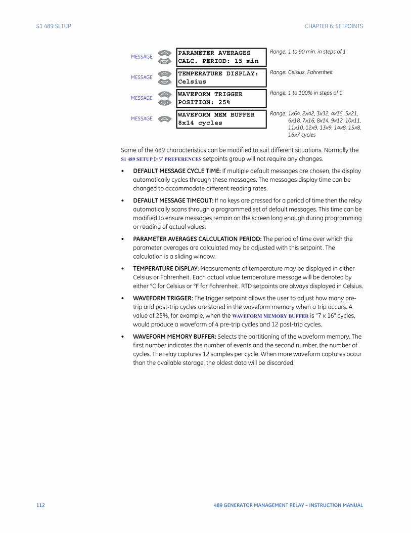
112 489 GENERATOR MANAGEMENT RELAY – INSTRUCTION MANUAL
S1 489 SETUP CHAPTER 6: SETPOINTS
Some of the 489 characteristics can be modified to suit different situations. Normally the S1 489 SETUP PREFERENCES setpoints group will not require any changes.
• DEFAULT MESSAGE CYCLE TIME: If multiple default messages are chosen, the display automatically cycles through these messages. The messages display time can be changed to accommodate different reading rates.
• DEFAULT MESSAGE TIMEOUT: If no keys are pressed for a period of time then the relay automatically scans through a programmed set of default messages. This time can be modified to ensure messages remain on the screen long enough during programming or reading of actual values.
• PARAMETER AVERAGES CALCULATION PERIOD: The period of time over which the parameter averages are calculated may be adjusted with this setpoint. The calculation is a sliding window.
• TEMPERATURE DISPLAY: Measurements of temperature may be displayed in either Celsius or Fahrenheit. Each actual value temperature message will be denoted by either °C for Celsius or °F for Fahrenheit. RTD setpoints are always displayed in Celsius.
• WAVEFORM TRIGGER: The trigger setpoint allows the user to adjust how many pre-trip and post-trip cycles are stored in the waveform memory when a trip occurs. A value of 25%, for example, when the WAVEFORM MEMORY BUFFER is “7 x 16" cycles, would produce a waveform of 4 pre-trip cycles and 12 post-trip cycles.
• WAVEFORM MEMORY BUFFER: Selects the partitioning of the waveform memory. The first number indicates the number of events and the second number, the number of cycles. The relay captures 12 samples per cycle. When more waveform captures occur than the available storage, the oldest data will be discarded.
MESSAGEPARAMETER AVERAGESCALC. PERIOD: 15 min
Range: 1 to 90 min. in steps of 1
MESSAGETEMPERATURE DISPLAY:Celsius
Range: Celsius, Fahrenheit
MESSAGEWAVEFORM TRIGGERPOSITION: 25%
Range: 1 to 100% in steps of 1
MESSAGEWAVEFORM MEM BUFFER8x14 cycles
Range: 1x64, 2x42, 3x32, 4x35, 5x21, 6x18, 7x16, 8x14, 9x12, 10x11, 11x10, 12x9, 13x9, 14x8, 15x8, 16x7 cycles
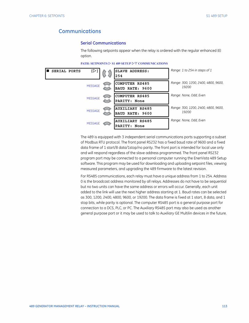
CHAPTER 6: SETPOINTS S1 489 SETUP
489 GENERATOR MANAGEMENT RELAY – INSTRUCTION MANUAL 113
Communications
Serial Communications
The following setpoints appear when the relay is ordered with the regular enhanced (E) option.
PATH: SETPOINTS S1 489 SETUP COMMUNICATIONS
The 489 is equipped with 3 independent serial communications ports supporting a subset of Modbus RTU protocol. The front panel RS232 has a fixed baud rate of 9600 and a fixed data frame of 1 start/8 data/1stop/no parity. The front port is intended for local use only and will respond regardless of the slave address programmed. The front panel RS232 program port may be connected to a personal computer running the EnerVista 489 Setup software. This program may be used for downloading and uploading setpoint files, viewing measured parameters, and upgrading the 489 firmware to the latest revision.
For RS485 communications, each relay must have a unique address from 1 to 254. Address 0 is the broadcast address monitored by all relays. Addresses do not have to be sequential but no two units can have the same address or errors will occur. Generally, each unit added to the link will use the next higher address starting at 1. Baud rates can be selected as 300, 1200, 2400, 4800, 9600, or 19200. The data frame is fixed at 1 start, 8 data, and 1 stop bits, while parity is optional. The computer RS485 port is a general purpose port for connection to a DCS, PLC, or PC. The Auxiliary RS485 port may also be used as another general purpose port or it may be used to talk to Auxiliary GE Multilin devices in the future.
SERIAL PORTS [] SLAVE ADDRESS:254
Range: 1 to 254 in steps of 1
MESSAGECOMPUTER RS485BAUD RATE: 9600
Range: 300, 1200, 2400, 4800, 9600, 19200
MESSAGECOMPUTER RS485PARITY: None
Range: None, Odd, Even
MESSAGEAUXILIARY RS485BAUD RATE: 9600
Range: 300, 1200, 2400, 4800, 9600, 19200
MESSAGEAUXILIARY RS485PARITY: None
Range: None, Odd, Even
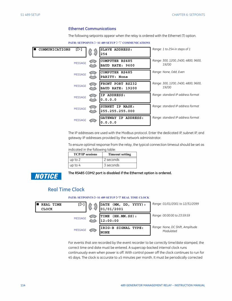
114 489 GENERATOR MANAGEMENT RELAY – INSTRUCTION MANUAL
S1 489 SETUP CHAPTER 6: SETPOINTS
Ethernet Communications
The following setpoints appear when the relay is ordered with the Ethernet (T) option.
PATH: SETPOINTS S1 489 SETUP COMMUNICATIONS
The IP addresses are used with the Modbus protocol. Enter the dedicated IP, subnet IP, and gateway IP addresses provided by the network administrator.
To ensure optimal response from the relay, the typical connection timeout should be set as indicated in the following table:
The RS485 COM2 port is disabled if the Ethernet option is ordered.
Real Time ClockPATH: SETPOINTS S1 489 SETUP REAL TIME CLOCK
For events that are recorded by the event recorder to be correctly time/date stamped, the correct time and date must be entered. A supercap-backed internal clock runs continuously even when power is off. With control power off the clock continues to run for 45 days. The clock is accurate to ±5 minutes per month. It must be periodically corrected
COMMUNICATIONS [] SLAVE ADDRESS:254
Range: 1 to 254 in steps of 1
MESSAGECOMPUTER RS485BAUD RATE: 9600
Range: 300, 1200, 2400, 4800, 9600, 19200
MESSAGECOMPUTER RS485PARITY: None
Range: None, Odd, Even
MESSAGEFRONT PORT RS232BAUD RATE: 19200
Range: 300, 1200, 2400, 4800, 9600, 19200
MESSAGEIP ADDRESS:0.0.0.0
Range: standard IP address format
MESSAGESUBNET IP MASK:255.255.255.000
Range: standard IP address format
MESSAGEGATEWAY IP ADDRESS:0.0.0.0
Range: standard IP address format
TCP/IP sessions Timeout setting
up to 2 2 seconds
up to 4 3 seconds
REAL TIME []CLOCK
DATE (MM, DD, YYYY):01/01/2001
Range: 01/01/2001 to 12/31/2099
MESSAGETIME (HH.MM.SS):12:00:00
Range: 00:00:00 to 23:59:59
MESSAGEIRIG-B SIGNAL TYPE:NONE
Range: None, DC Shift , Amplitude Modulated

CHAPTER 6: SETPOINTS S1 489 SETUP
489 GENERATOR MANAGEMENT RELAY – INSTRUCTION MANUAL 115
either manually through the front panel or via the clock update command over the RS485 serial link. If the approximate time an event occurred without synchronization to other relays is sufficient, then entry of time/date from the front panel keys is adequate.
If the RS485 serial communication link is used then all the relays can keep time in synchronization with each other. A new clock time is pre-loaded into the memory map via the RS485 communications port by a remote computer to each relay connected on the communications channel. The computer broadcasts (address 0) a “set clock” command to all relays. Then all relays in the system begin timing at the exact same instant. There can be up to 100 ms of delay in receiving serial commands so the clock time in each relay is ±100 ms, ± the absolute clock accuracy in the PLC or PC. See the chapter on Communications for information on programming the time preload and synchronizing commands.
An IRIG-B signal receiver may be connected to 489 units with hardware revision G or higher. The relay will continuously decode the time signal and set its internal time correspondingly. The “signal type” setpoint must be set to match the signal provided by the receiver.
Default MessagesPATH: SETPOINTS S1 489 SETUP DEFAULT MESSAGES
The 489 displays default messages after a period of keypad inactivity. Up to 20 default messages can be selected for display. If more than one message is chosen, they will automatically scroll at a rate determined by the S1 489 SETUP PREFERENCES DEFAULT
MESSAGE CYCLE TIME setpoint. Any actual value can be selected for display. In addition, up to 5 user-programmable messages can be created and displayed with the message
DEFAULT []MESSAGES
GENERATOR STATUS:Stopped
Range: N/A
MESSAGEA: 0 B: 0C: 0 Amps
Range: N/A
MESSAGEVab: 0 Vbc: 0Vca: 0 Volts
Range: N/A
MESSAGEFREQUENCY:0.00 Hz
Range: N/A
MESSAGEPOWER FACTOR:0.00
Range: N/A
MESSAGEREAL POWER:
0 MW
Range: N/A
MESSAGEREACTIVE POWER
0 Mvar
Range: N/A
MESSAGEDATE: 01/01/2001TIME: 12:00:00
Range: N/A
MESSAGEGE MULTILIN489 GENERATOR RELAY
Range: N/A
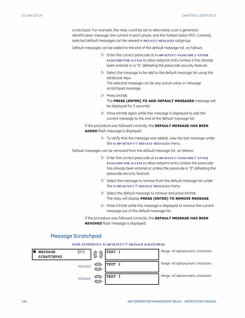
116 489 GENERATOR MANAGEMENT RELAY – INSTRUCTION MANUAL
S1 489 SETUP CHAPTER 6: SETPOINTS
scratchpad. For example, the relay could be set to alternately scan a generator identification message, the current in each phase, and the hottest stator RTD. Currently selected default messages can be viewed in DEFAULT MESSAGES subgroup.
Default messages can be added to the end of the default message list, as follows:
Enter the correct passcode at S1 489 SETUP PASSCODE ENTER
PASSCODE FOR ACCESS to allow setpoint entry (unless it has already been entered or is “0”, defeating the passcode security feature).
Select the message to be add to the default message list using the MESSAGE keys. The selected message can be any actual value or message scratchpad message.
Press ENTER. The PRESS [ENTER] TO ADD DEFAULT MESSAGES message will be displayed for 5 seconds:
Press ENTER again while this message is displayed to add the current message to the end of the default message list.
If the procedure was followed correctly, the DEFAULT MESSAGE HAS BEEN ADDED flash message is displayed:
To verify that the message was added, view the last message under the S1 489 SETUP DEFAULT MESSAGES menu.
Default messages can be removed from the default message list, as follows:
Enter the correct passcode at S1 489 SETUP PASSCODE ENTER
PASSCODE FOR ACCESS to allow setpoint entry (unless the passcode has already been entered or unless the passcode is “0” defeating the passcode security feature).
Select the message to remove from the default message list under the S1 489 SETUP DEFAULT MESSAGES menu.
Select the default message to remove and press ENTER. The relay will display PRESS [ENTER] TO REMOVE MESSAGE.
Press ENTER while this message is displayed to remove the current message out of the default message list.
If the procedure was followed correctly, the DEFAULT MESSAGE HAS BEEN REVOVED flash message is displayed.
Message ScratchpadPATH: SETPOINTS S1 489 SETUP MESSAGE SCRATCHPAD
MESSAGE []SCRATCHPAD
TEXT 1 Range: 40 alphanumeric characters
MESSAGETEXT 2 Range: 40 alphanumeric characters
MESSAGETEXT 3 Range: 40 alphanumeric characters

CHAPTER 6: SETPOINTS S1 489 SETUP
489 GENERATOR MANAGEMENT RELAY – INSTRUCTION MANUAL 117
Up to 5 message screens can be programmed under the message scratchpad area. These messages may be notes that pertain to the installation of the generator. In addition, these notes may be selected for scanning during default message display. This might be useful for reminding operators to perform certain tasks. The messages may be entered from the communications ports or through the keypad. To enter a 40 character message:
Select the user message to be changed.
Press the decimal [.] key to enter text mode. An underscore cursor will appear under the first character.
Use the VALUE keys to display the desired character. A space is selected like a character.
Press the [.] key to advance to the next character. To skip over a character press the [.] key. If an incorrect character is accidentally stored, press the [.] key enough times to scroll the cursor around to the character.
When the desired message is displayed press the ENTER key to store or the ESCAPE key to abort. The message is now permanently stored.
Press ESCAPE to cancel the altered message.
Clear DataPATH: SETPOINTS S1 489 SETUP CLEAR DATA
MESSAGETEXT 4 Range: 40 alphanumeric characters
MESSAGEGE MULTILIN489 GENERATOR RELAY
Range: 40 alphanumeric characters
CLEAR DATA [] CLEAR LAST TRIPDATA: No
Range: No, Yes
MESSAGECLEAR MWh and MvarhMETERS: No
Range: No, Yes
MESSAGECLEAR PEAK DEMANDDATA: No
Range: No, Yes
MESSAGECLEAR RTDMAXIMUMS: No
Range: No, Yes
MESSAGECLEAR ANALOG I/PMIN/MAX: No
Range: No, Yes
MESSAGECLEAR TRIPCOUNTERS: No
Range: No, Yes
MESSAGECLEAR EVENTRECORD: No
Range: No, Yes
MESSAGECLEAR GENERATORINFORMATION: No
Range: No, Yes

118 489 GENERATOR MANAGEMENT RELAY – INSTRUCTION MANUAL
S1 489 SETUP CHAPTER 6: SETPOINTS
These commands may be used to clear various historical data.
• CLEAR LAST TRIP DATA: The Last Trip Data may be cleared by executing this command.
• CLEAR MWh and Mvarh METERS: Executing this command will clear the MWh and Mvarh metering to zero.
• CLEAR PEAK DEMAND DATA: Execute this command to clear peak demand values.
• CLEAR RTD MAXIMUMS: All maximum RTD temperature measurements are stored and updated each time a new maximum temperature is established. Execute this command to clear the maximum values.
• CLEAR ANALOG I/P MIN/MAX: The minimum and maximum analog input values are stored for each Analog Input. Those minimum and maximum values may be cleared at any time.
• CLEAR TRIP COUNTERS: There are counters for each possible type of trip. Those counters may be cleared by executing this command.
• CLEAR EVENT RECORD: The event recorder saves the last 256 events, automatically overwriting the oldest event. If desired, all events can be cleared using this command to prevent confusion with old information.
• CLEAR GENERATOR INFORMATION: The number of thermal resets and the total generator running hours can be viewed in actual values. On a new installation, or if new equipment is installed, this information is cleared through this setpoint.
• CLEAR BREAKER INFORMATION: The total number of breaker operations can be viewed in actual values. On a new installation or if maintenance work is done on the breaker, this accumulator can be cleared with this setpoint.
MESSAGECLEAR BREAKERINFORMATION: No
Range: No, Yes
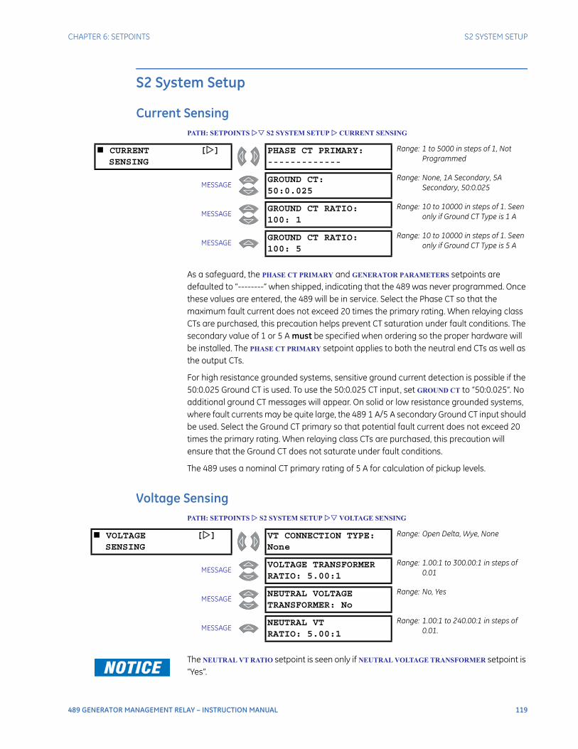
CHAPTER 6: SETPOINTS S2 SYSTEM SETUP
489 GENERATOR MANAGEMENT RELAY – INSTRUCTION MANUAL 119
S2 System Setup
Current SensingPATH: SETPOINTS S2 SYSTEM SETUP CURRENT SENSING
As a safeguard, the PHASE CT PRIMARY and GENERATOR PARAMETERS setpoints are defaulted to “--------” when shipped, indicating that the 489 was never programmed. Once these values are entered, the 489 will be in service. Select the Phase CT so that the maximum fault current does not exceed 20 times the primary rating. When relaying class CTs are purchased, this precaution helps prevent CT saturation under fault conditions. The secondary value of 1 or 5 A must be specified when ordering so the proper hardware will be installed. The PHASE CT PRIMARY setpoint applies to both the neutral end CTs as well as the output CTs.
For high resistance grounded systems, sensitive ground current detection is possible if the 50:0.025 Ground CT is used. To use the 50:0.025 CT input, set GROUND CT to “50:0.025”. No additional ground CT messages will appear. On solid or low resistance grounded systems, where fault currents may be quite large, the 489 1 A/5 A secondary Ground CT input should be used. Select the Ground CT primary so that potential fault current does not exceed 20 times the primary rating. When relaying class CTs are purchased, this precaution will ensure that the Ground CT does not saturate under fault conditions.
The 489 uses a nominal CT primary rating of 5 A for calculation of pickup levels.
Voltage SensingPATH: SETPOINTS S2 SYSTEM SETUP VOLTAGE SENSING
The NEUTRAL VT RATIO setpoint is seen only if NEUTRAL VOLTAGE TRANSFORMER setpoint is “Yes”.
CURRENT []SENSING
PHASE CT PRIMARY:-------------
Range: 1 to 5000 in steps of 1, Not Programmed
MESSAGEGROUND CT:50:0.025
Range: None, 1A Secondary, 5A Secondary, 50:0.025
MESSAGEGROUND CT RATIO:100: 1
Range: 10 to 10000 in steps of 1. Seen only if Ground CT Type is 1 A
MESSAGEGROUND CT RATIO:100: 5
Range: 10 to 10000 in steps of 1. Seen only if Ground CT Type is 5 A
VOLTAGE []SENSING
VT CONNECTION TYPE:None
Range: Open Delta, Wye, None
MESSAGEVOLTAGE TRANSFORMERRATIO: 5.00:1
Range: 1.00:1 to 300.00:1 in steps of 0.01
MESSAGENEUTRAL VOLTAGETRANSFORMER: No
Range: No, Yes
MESSAGENEUTRAL VTRATIO: 5.00:1
Range: 1.00:1 to 240.00:1 in steps of 0.01.
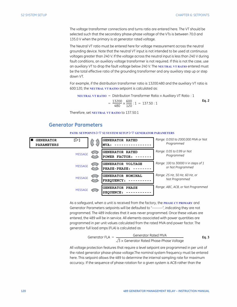
120 489 GENERATOR MANAGEMENT RELAY – INSTRUCTION MANUAL
S2 SYSTEM SETUP CHAPTER 6: SETPOINTS
The voltage transformer connections and turns ratio are entered here. The VT should be selected such that the secondary phase-phase voltage of the VTs is between 70.0 and 135.0 V when the primary is at generator rated voltage.
The Neutral VT ratio must be entered here for voltage measurement across the neutral grounding device. Note that the neutral VT input is not intended to be used at continuous voltages greater than 240 V. If the voltage across the neutral input is less than 240 V during fault conditions, an auxiliary voltage transformer is not required. If this is not the case, use an auxiliary VT to drop the fault voltage below 240 V. The NEUTRAL VT RATIO entered must be the total effective ratio of the grounding transformer and any auxiliary step up or step down VT.
For example, if the distribution transformer ratio is 13200:480 and the auxiliary VT ratio is 600:120, the NEUTRAL VT RATIO setpoint is calculated as:
Eq. 2
Therefore, set NEUTRAL VT RATIO to 137.50:1
Generator ParametersPATH: SETPOINTS S2 SYSTEM SETUP GENERATOR PARAMETERS
As a safeguard, when a unit is received from the factory, the PHASE CT PRIMARY and Generator Parameters setpoints will be defaulted to “--------”, indicating they are not programmed. The 489 indicates that it was never programmed. Once these values are entered, the 489 will be in service. All elements associated with power quantities are programmed in per unit values calculated from the rated MVA and power factor. The generator full load amps (FLA) is calculated as
Eq. 3
All voltage protection features that require a level setpoint are programmed in per unit of the rated generator phase-phase voltage.The nominal system frequency must be entered here. This setpoint allows the 489 to determine the internal sampling rate for maximum accuracy. If the sequence of phase rotation for a given system is ACB rather than the
NEUTRAL VT RATIO Distribution Transformer Ratio Auxiliary VT Ratio× : 1=
13200480
--------------- 600120---------× : 1 137.50 : 1= =
GENERATOR []PARAMETERS
GENERATOR RATEDMVA: ----------------
Range: 0.050 to 2000.000 MVA or NotProgrammed
MESSAGEGENERATOR RATEDPOWER FACTOR: -------
Range: 0.05 to 0.99 or NotProgrammed
MESSAGEGENERATOR VOLTAGEPHASE-PHASE: --------
Range: 100 to 30000 V in steps of 1or Not Programmed
MESSAGEGENERATOR NOMINALFREQUENCY: ----------
Range: 25 Hz, 50 Hz, 60 Hz, orNot Programmed
MESSAGEGENERATOR PHASESEQUENCE: -----------
Range: ABC, ACB, or Not Programmed
Generator FLA Generator Rated MVA
3 Generator Rated Phase-Phase Voltage×--------------------------------------------------------------------------------------------------------------=
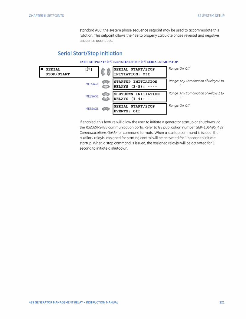
CHAPTER 6: SETPOINTS S2 SYSTEM SETUP
489 GENERATOR MANAGEMENT RELAY – INSTRUCTION MANUAL 121
standard ABC, the system phase sequence setpoint may be used to accommodate this rotation. This setpoint allows the 489 to properly calculate phase reversal and negative sequence quantities.
Serial Start/Stop InitiationPATH: SETPOINTS S2 SYSTEM SETUP SERIAL START/STOP
If enabled, this feature will allow the user to initiate a generator startup or shutdown via the RS232/RS485 communication ports. Refer to GE publication number GEK-106495: 489 Communications Guide for command formats. When a startup command is issued, the auxiliary relay(s) assigned for starting control will be activated for 1 second to initiate startup. When a stop command is issued, the assigned relay(s) will be activated for 1 second to initiate a shutdown.
SERIAL []STOP/START
SERIAL START/STOPINITIATION: Off
Range: On, Off
MESSAGESTARTUP INITIATIONRELAYS (2-5): ----
Range: Any Combination of Relays 2 to 5
MESSAGESHUTDOWN INITIATIONRELAYS (1-4): ----
Range: Any Combination of Relays 1 to 4
MESSAGESERIAL START/STOPEVENTS: Off
Range: On, Off
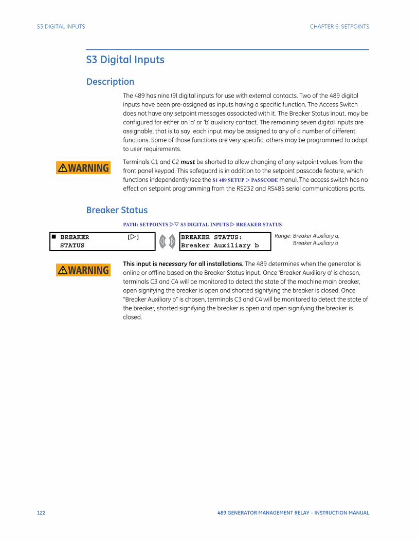
122 489 GENERATOR MANAGEMENT RELAY – INSTRUCTION MANUAL
S3 DIGITAL INPUTS CHAPTER 6: SETPOINTS
S3 Digital Inputs
DescriptionThe 489 has nine (9) digital inputs for use with external contacts. Two of the 489 digital inputs have been pre-assigned as inputs having a specific function. The Access Switch does not have any setpoint messages associated with it . The Breaker Status input, may be configured for either an 'a' or 'b' auxiliary contact. The remaining seven digital inputs are assignable; that is to say, each input may be assigned to any of a number of different functions. Some of those functions are very specific, others may be programmed to adapt to user requirements.
Terminals C1 and C2 must be shorted to allow changing of any setpoint values from the front panel keypad. This safeguard is in addition to the setpoint passcode feature, which functions independently (see the S1 489 SETUP PASSCODE menu). The access switch has no effect on setpoint programming from the RS232 and RS485 serial communications ports.
Breaker StatusPATH: SETPOINTS S3 DIGITAL INPUTS BREAKER STATUS
This input is necessary for all installations. The 489 determines when the generator is online or offline based on the Breaker Status input. Once 'Breaker Auxiliary a' is chosen, terminals C3 and C4 will be monitored to detect the state of the machine main breaker, open signifying the breaker is open and shorted signifying the breaker is closed. Once “Breaker Auxiliary b” is chosen, terminals C3 and C4 will be monitored to detect the state of the breaker, shorted signifying the breaker is open and open signifying the breaker is closed.
BREAKER []STATUS
BREAKER STATUS:Breaker Auxiliary b
Range: Breaker Auxiliary a,Breaker Auxiliary b
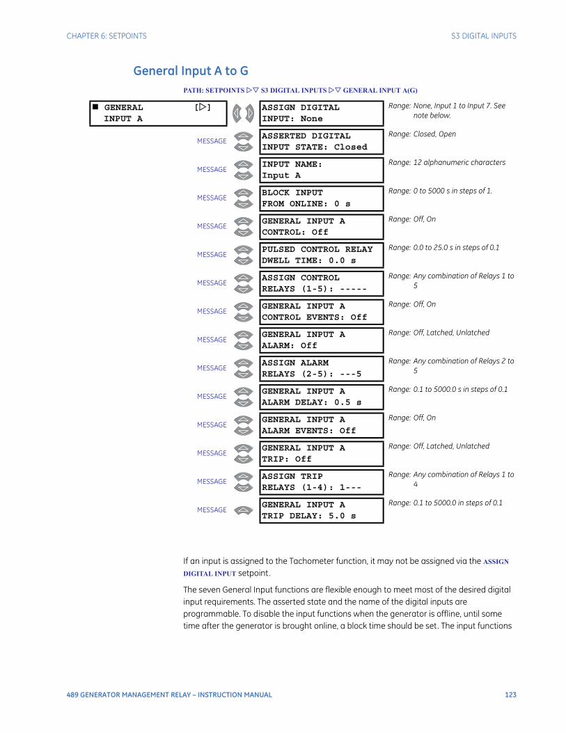
CHAPTER 6: SETPOINTS S3 DIGITAL INPUTS
489 GENERATOR MANAGEMENT RELAY – INSTRUCTION MANUAL 123
General Input A to GPATH: SETPOINTS S3 DIGITAL INPUTS GENERAL INPUT A(G)
If an input is assigned to the Tachometer function, it may not be assigned via the ASSIGN
DIGITAL INPUT setpoint.
The seven General Input functions are flexible enough to meet most of the desired digital input requirements. The asserted state and the name of the digital inputs are programmable. To disable the input functions when the generator is offline, until some time after the generator is brought online, a block time should be set. The input functions
GENERAL []INPUT A
ASSIGN DIGITALINPUT: None
Range: None, Input 1 to Input 7. See note below.
MESSAGEASSERTED DIGITALINPUT STATE: Closed
Range: Closed, Open
MESSAGEINPUT NAME:Input A
Range: 12 alphanumeric characters
MESSAGEBLOCK INPUTFROM ONLINE: 0 s
Range: 0 to 5000 s in steps of 1.
MESSAGEGENERAL INPUT ACONTROL: Off
Range: Off, On
MESSAGEPULSED CONTROL RELAYDWELL TIME: 0.0 s
Range: 0.0 to 25.0 s in steps of 0.1
MESSAGEASSIGN CONTROLRELAYS (1-5): -----
Range: Any combination of Relays 1 to 5
MESSAGEGENERAL INPUT ACONTROL EVENTS: Off
Range: Off, On
MESSAGEGENERAL INPUT AALARM: Off
Range: Off, Latched, Unlatched
MESSAGEASSIGN ALARMRELAYS (2-5): ---5
Range: Any combination of Relays 2 to 5
MESSAGEGENERAL INPUT AALARM DELAY: 0.5 s
Range: 0.1 to 5000.0 s in steps of 0.1
MESSAGEGENERAL INPUT AALARM EVENTS: Off
Range: Off, On
MESSAGEGENERAL INPUT ATRIP: Off
Range: Off, Latched, Unlatched
MESSAGEASSIGN TRIPRELAYS (1-4): 1---
Range: Any combination of Relays 1 to 4
MESSAGEGENERAL INPUT ATRIP DELAY: 5.0 s
Range: 0.1 to 5000.0 in steps of 0.1

124 489 GENERATOR MANAGEMENT RELAY – INSTRUCTION MANUAL
S3 DIGITAL INPUTS CHAPTER 6: SETPOINTS
will be enabled once the block delay has expired. A value of “0 s” for the BLOCK INPUT FROM
ONLINE block time indicates that the input functions are always enabled while the generator is offline as well as online.
Inputs may be configured for control, alarm, or trip. If the control feature is enabled, the assigned output relay(s) operate when the input is asserted. If the PULSED CONTROL RELAY
DWELL TIME is set to “0”, the output relay(s) operate only while the input is asserted. However, if a dwell time is assigned, the output relay(s) operate as soon as the input is asserted for a period of time specified by the setpoint. If an alarm or trip is enabled and the input is asserted, an alarm or trip will occur after the specified delay.
Remote ResetPATH: SETPOINTS S3 DIGITAL INPUTS REMOTE RESET
Once an input is assigned to the Remote Reset function, shorting that input will reset any latched trips or alarms that may be active, provided that any thermal lockout time has expired and the condition that caused the alarm or trip is no longer present.
If an input is assigned to the tachometer function, it may not be used here.
Test InputPATH: SETPOINTS S3 DIGITAL INPUTS TEST INPUT
Once the 489 is in service, it may be tested from time to time as part of a regular maintenance schedule. The unit will have accumulated statistical information relating historically to generator and breaker operation. This information includes: last trip data, peak demand data, MWh and Mvarh metering, parameter averages, RTD maximums, analog input minimums and maximums, number of trips, number of trips by type, number of breaker operations, the number of thermal resets, total generator running hours, and the event record. When the unit is under test and one of the inputs is assigned to the Test Input function, shorting that input will prevent all of this data from being corrupted or updated.
If an input is assigned to the tachometer function, it may not be used here.
Thermal ResetPATH: SETPOINTS S3 DIGITAL INPUTS THERMAL RESET
During testing or in an emergency, it may be desirable to reset the thermal memory used to zero. If an input is assigned to the Thermal Reset function, shorting that input will reset the thermal memory used to zero. All Thermal Resets will be recorded as events.
REMOTE RESET [] ASSIGN DIGITALINPUT: None
Range: None, Input 1, Input 2, Input 3, Input 4, Input 5, Input 6, Input 7
TEST INPUT [] ASSIGN DIGITALINPUT: None
Range: None, Input 1, Input 2, Input 3, Input 4, Input 5, Input 6, Input 7
THERMAL RESET [] ASSIGN DIGITALINPUT: None
Range: None, Input 1, Input 2, Input 3, Input 4, Input 5, Input 6, Input 7
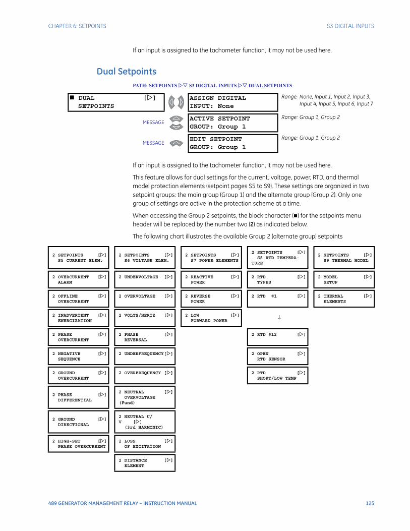
CHAPTER 6: SETPOINTS S3 DIGITAL INPUTS
489 GENERATOR MANAGEMENT RELAY – INSTRUCTION MANUAL 125
If an input is assigned to the tachometer function, it may not be used here.
Dual SetpointsPATH: SETPOINTS S3 DIGITAL INPUTS DUAL SETPOINTS
If an input is assigned to the tachometer function, it may not be used here.
This feature allows for dual settings for the current, voltage, power, RTD, and thermal model protection elements (setpoint pages S5 to S9). These settings are organized in two setpoint groups: the main group (Group 1) and the alternate group (Group 2). Only one group of settings are active in the protection scheme at a time.
When accessing the Group 2 setpoints, the block character () for the setpoints menu header will be replaced by the number two (2) as indicated below.
The following chart illustrates the available Group 2 (alternate group) setpoints
DUAL []SETPOINTS
ASSIGN DIGITALINPUT: None
Range: None, Input 1, Input 2, Input 3, Input 4, Input 5, Input 6, Input 7
MESSAGEACTIVE SETPOINTGROUP: Group 1
Range: Group 1, Group 2
MESSAGEEDIT SETPOINTGROUP: Group 1
Range: Group 1, Group 2
2 SETPOINTS []S5 CURRENT ELEM.
2 SETPOINTS []S6 VOLTAGE ELEM.
2 SETPOINTS []S7 POWER ELEMENTS
2 SETPOINTS []S8 RTD TEMPERA-
TURE
2 SETPOINTS []S9 THERMAL MODEL
2 OVERCURRENT []ALARM
2 UNDERVOLTAGE [] 2 REACTIVE []POWER
2 RTD []TYPES
2 MODEL []SETUP
2 OFFLINE []OVERCURRENT
2 OVERVOLTAGE [] 2 REVERSE []POWER
2 RTD #1 [] 2 THERMAL []ELEMENTS
2 INADVERTENT []ENERGIZATION
2 VOLTS/HERTZ [] 2 LOW []FORWARD POWER
↓
2 PHASE []OVERCURRENT
2 PHASE []REVERSAL
2 RTD #12 []
2 NEGATIVE []SEQUENCE
2 UNDERFREQUENCY[] 2 OPEN []RTD SENSOR
2 GROUND []OVERCURRENT
2 OVERFREQUENCY [] 2 RTD []SHORT/LOW TEMP
2 PHASE []DIFFERENTIAL
2 NEUTRAL []OVERVOLTAGE
(Fund)
2 GROUND []DIRECTIONAL
2 NEUTRAL U/V []
(3rd HARMONIC)
2 HIGH-SET []PHASE OVERCURRENT
2 LOSS []OF EXCITATION
2 DISTANCE []ELEMENT
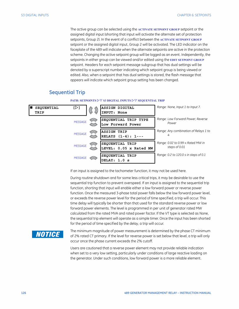
126 489 GENERATOR MANAGEMENT RELAY – INSTRUCTION MANUAL
S3 DIGITAL INPUTS CHAPTER 6: SETPOINTS
The active group can be selected using the ACTIVATE SETPOINT GROUP setpoint or the assigned digital input (shorting that input will activate the alternate set of protection setpoints, Group 2). In the event of a conflict between the ACTIVATE SETPOINT GROUP setpoint or the assigned digital input, Group 2 will be activated. The LED indicator on the faceplate of the 489 will indicate when the alternate setpoints are active in the protection scheme. Changing the active setpoint group will be logged as an event. Independently, the setpoints in either group can be viewed and/or edited using the EDIT SETPOINT GROUP setpoint. Headers for each setpoint message subgroup that has dual settings will be denoted by a superscript number indicating which setpoint group is being viewed or edited. Also, when a setpoint that has dual settings is stored, the flash message that appears will indicate which setpoint group setting has been changed.
Sequential TripPATH: SETPOINTS S3 DIGITAL INPUTS SEQUENTIAL TRIP
If an input is assigned to the tachometer function, it may not be used here.
During routine shutdown and for some less critical trips, it may be desirable to use the sequential trip function to prevent overspeed. If an input is assigned to the sequential trip function, shorting that input will enable either a low forward power or reverse power function. Once the measured 3-phase total power falls below the low forward power level, or exceeds the reverse power level for the period of time specified, a trip will occur. This time delay will typically be shorter than that used for the standard reverse power or low forward power elements. The level is programmed in per unit of generator rated MW calculated from the rated MVA and rated power factor. If the VT type is selected as None, the sequential trip element will operate as a simple timer. Once the input has been shorted for the period of time specified by the delay, a trip will occur.
The minimum magnitude of power measurement is determined by the phase CT minimum of 2% rated CT primary. If the level for reverse power is set below that level, a trip will only occur once the phase current exceeds the 2% cutoff.
Users are cautioned that a reverse power element may not provide reliable indication when set to a very low setting, particularly under conditions of large reactive loading on the generator. Under such conditions, low forward power is a more reliable element.
SEQUENTIAL []TRIP
ASSIGN DIGITALINPUT: None
Range: None, Input 1 to Input 7.
MESSAGESEQUENTIAL TRIP TYPELow Forward Power
Range: Low Forward Power, Reverse Power
MESSAGEASSIGN TRIPRELAYS (1-4): 1---
Range: Any combination of Relays 1 to 4
MESSAGESEQUENTIAL TRIPLEVEL: 0.05 x Rated MW
Range: 0.02 to 0.99 × Rated MW in steps of 0.01
MESSAGESEQUENTIAL TRIPDELAY: 1.0 s
Range: 0.2 to 120.0 s in steps of 0.1
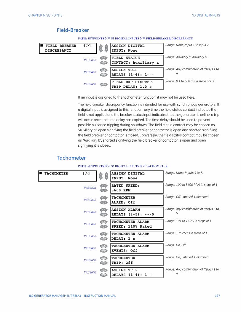
CHAPTER 6: SETPOINTS S3 DIGITAL INPUTS
489 GENERATOR MANAGEMENT RELAY – INSTRUCTION MANUAL 127
Field-BreakerPATH: SETPOINTS S3 DIGITAL INPUTS FIELD-BREAKER DISCREPANCY
If an input is assigned to the tachometer function, it may not be used here.
The field-breaker discrepancy function is intended for use with synchronous generators. If a digital input is assigned to this function, any time the field status contact indicates the field is not applied and the breaker status input indicates that the generator is online, a trip will occur once the time delay has expired. The time delay should be used to prevent possible nuisance tripping during shutdown. The field status contact may be chosen as “Auxiliary a”, open signifying the field breaker or contactor is open and shorted signifying the field breaker or contactor is closed. Conversely, the field status contact may be chosen as “Auxiliary b”, shorted signifying the field breaker or contactor is open and open signifying it is closed.
TachometerPATH: SETPOINTS S3 DIGITAL INPUTS TACHOMETER
FIELD-BREAKER []DISCREPANCY
ASSIGN DIGITALINPUT: None
Range: None, Input 1 to Input 7
MESSAGEFIELD STATUSCONTACT: Auxiliary a
Range: Auxiliary a, Auxiliary b
MESSAGEASSIGN TRIPRELAYS (1-4): 1---
Range: Any combination of Relays 1 to 4
MESSAGEFIELD-BKR DISCREP.TRIP DELAY: 1.0 s
Range: 0.1 to 500.0 s in steps of 0.1
TACHOMETER [] ASSIGN DIGITALINPUT: None
Range: None, Inputs 4 to 7.
MESSAGERATED SPEED:3600 RPM
Range: 100 to 3600 RPM in steps of 1
MESSAGETACHOMETERALARM: Off
Range: Off, Latched, Unlatched
MESSAGEASSIGN ALARMRELAYS (2-5): ---5
Range: Any combination of Relays 2 to 5
MESSAGETACHOMETER ALARMSPEED: 110% Rated
Range: 101 to 175% in steps of 1
MESSAGETACHOMETER ALARMDELAY: 1 s
Range: 1 to 250 s in steps of 1
MESSAGETACHOMETER ALARMEVENTS: Off
Range: On, Off
MESSAGETACHOMETERTRIP: Off
Range: Off, Latched, Unlatched
MESSAGEASSIGN TRIPRELAYS (1-4): 1---
Range: Any combination of Relays 1 to 4
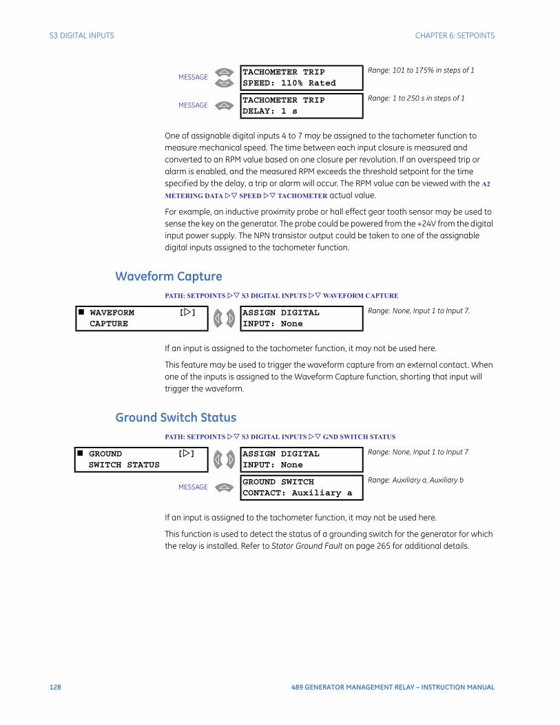
128 489 GENERATOR MANAGEMENT RELAY – INSTRUCTION MANUAL
S3 DIGITAL INPUTS CHAPTER 6: SETPOINTS
One of assignable digital inputs 4 to 7 may be assigned to the tachometer function to measure mechanical speed. The time between each input closure is measured and converted to an RPM value based on one closure per revolution. If an overspeed trip or alarm is enabled, and the measured RPM exceeds the threshold setpoint for the time specified by the delay, a trip or alarm will occur. The RPM value can be viewed with the A2
METERING DATA SPEED TACHOMETER actual value.
For example, an inductive proximity probe or hall effect gear tooth sensor may be used to sense the key on the generator. The probe could be powered from the +24V from the digital input power supply. The NPN transistor output could be taken to one of the assignable digital inputs assigned to the tachometer function.
Waveform CapturePATH: SETPOINTS S3 DIGITAL INPUTS WAVEFORM CAPTURE
If an input is assigned to the tachometer function, it may not be used here.
This feature may be used to trigger the waveform capture from an external contact. When one of the inputs is assigned to the Waveform Capture function, shorting that input will trigger the waveform.
Ground Switch StatusPATH: SETPOINTS S3 DIGITAL INPUTS GND SWITCH STATUS
If an input is assigned to the tachometer function, it may not be used here.
This function is used to detect the status of a grounding switch for the generator for which the relay is installed. Refer to Stator Ground Fault on page 265 for additional details.
MESSAGETACHOMETER TRIPSPEED: 110% Rated
Range: 101 to 175% in steps of 1
MESSAGETACHOMETER TRIPDELAY: 1 s
Range: 1 to 250 s in steps of 1
WAVEFORM []CAPTURE
ASSIGN DIGITALINPUT: None
Range: None, Input 1 to Input 7.
GROUND []SWITCH STATUS
ASSIGN DIGITALINPUT: None
Range: None, Input 1 to Input 7
MESSAGEGROUND SWITCHCONTACT: Auxiliary a
Range: Auxiliary a, Auxiliary b
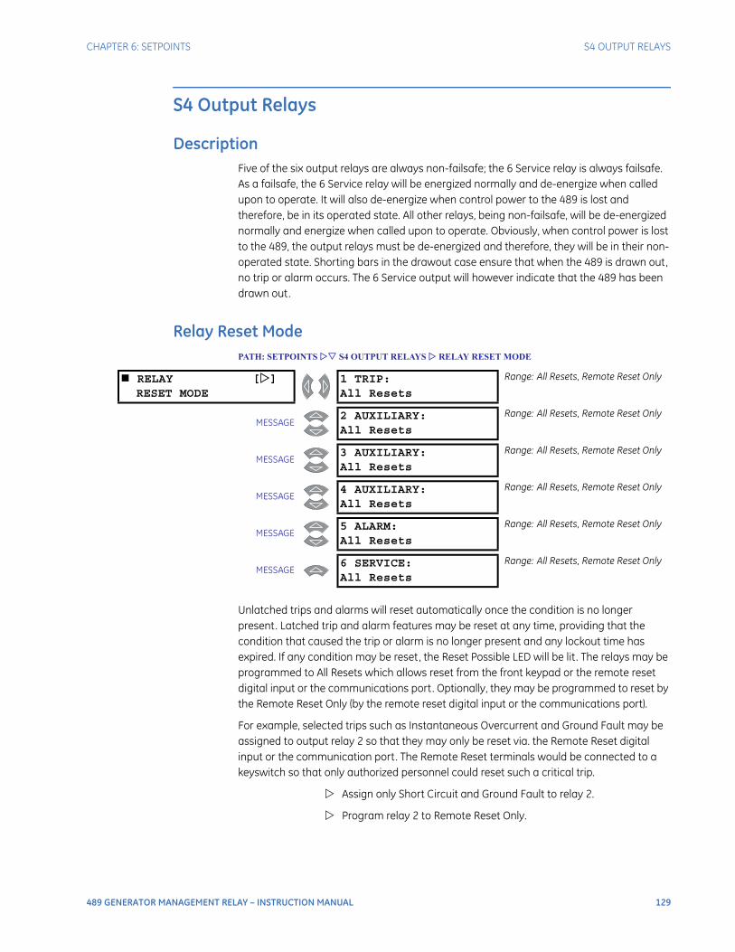
CHAPTER 6: SETPOINTS S4 OUTPUT RELAYS
489 GENERATOR MANAGEMENT RELAY – INSTRUCTION MANUAL 129
S4 Output Relays
DescriptionFive of the six output relays are always non-failsafe; the 6 Service relay is always failsafe. As a failsafe, the 6 Service relay will be energized normally and de-energize when called upon to operate. It will also de-energize when control power to the 489 is lost and therefore, be in its operated state. All other relays, being non-failsafe, will be de-energized normally and energize when called upon to operate. Obviously, when control power is lost to the 489, the output relays must be de-energized and therefore, they will be in their non-operated state. Shorting bars in the drawout case ensure that when the 489 is drawn out, no trip or alarm occurs. The 6 Service output will however indicate that the 489 has been drawn out.
Relay Reset ModePATH: SETPOINTS S4 OUTPUT RELAYS RELAY RESET MODE
Unlatched trips and alarms will reset automatically once the condition is no longer present. Latched trip and alarm features may be reset at any time, providing that the condition that caused the trip or alarm is no longer present and any lockout time has expired. If any condition may be reset, the Reset Possible LED will be lit . The relays may be programmed to All Resets which allows reset from the front keypad or the remote reset digital input or the communications port. Optionally, they may be programmed to reset by the Remote Reset Only (by the remote reset digital input or the communications port).
For example, selected trips such as Instantaneous Overcurrent and Ground Fault may be assigned to output relay 2 so that they may only be reset via. the Remote Reset digital input or the communication port. The Remote Reset terminals would be connected to a keyswitch so that only authorized personnel could reset such a critical trip.
Assign only Short Circuit and Ground Fault to relay 2.
Program relay 2 to Remote Reset Only.
RELAY []RESET MODE
1 TRIP:All Resets
Range: All Resets, Remote Reset Only
MESSAGE2 AUXILIARY:All Resets
Range: All Resets, Remote Reset Only
MESSAGE3 AUXILIARY:All Resets
Range: All Resets, Remote Reset Only
MESSAGE4 AUXILIARY:All Resets
Range: All Resets, Remote Reset Only
MESSAGE5 ALARM:All Resets
Range: All Resets, Remote Reset Only
MESSAGE6 SERVICE:All Resets
Range: All Resets, Remote Reset Only
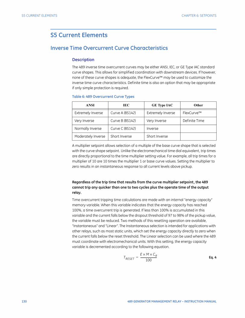
130 489 GENERATOR MANAGEMENT RELAY – INSTRUCTION MANUAL
S5 CURRENT ELEMENTS CHAPTER 6: SETPOINTS
S5 Current Elements
Inverse Time Overcurrent Curve Characteristics
Description
The 489 inverse time overcurrent curves may be either ANSI, IEC, or GE Type IAC standard curve shapes. This allows for simplified coordination with downstream devices. If however, none of these curve shapes is adequate, the FlexCurve™ may be used to customize the inverse time curve characteristics. Definite time is also an option that may be appropriate if only simple protection is required.
A multiplier setpoint allows selection of a multiple of the base curve shape that is selected with the curve shape setpoint. Unlike the electromechanical time dial equivalent, trip times are directly proportional to the time multiplier setting value. For example, all trip times for a multiplier of 10 are 10 times the multiplier 1 or base curve values. Setting the multiplier to zero results in an instantaneous response to all current levels above pickup.
Regardless of the trip time that results from the curve multiplier setpoint, the 489 cannot trip any quicker than one to two cycles plus the operate time of the output relay.
Time overcurrent tripping time calculations are made with an internal “energy capacity” memory variable. When this variable indicates that the energy capacity has reached 100%, a time overcurrent trip is generated. If less than 100% is accumulated in this variable and the current falls below the dropout threshold of 97 to 98% of the pickup value, the variable must be reduced. Two methods of this resetting operation are available, “Instantaneous” and “Linear”. The Instantaneous selection is intended for applications with other relays, such as most static units, which set the energy capacity directly to zero when the current falls below the reset threshold. The Linear selection can be used where the 489 must coordinate with electromechanical units. With this setting, the energy capacity variable is decremented according to the following equation.
Eq. 4
Table 6: 489 Overcurrent Curve Types
ANSI IEC GE Type IAC Other
Extremely Inverse Curve A (BS142) Extremely Inverse FlexCurve™
Very Inverse Curve B (BS142) Very Inverse Definite Time
Normally Inverse Curve C (BS142) Inverse
Moderately Inverse Short Inverse Short Inverse
TRESETE M CR××
100--------------------------=

CHAPTER 6: SETPOINTS S5 CURRENT ELEMENTS
489 GENERATOR MANAGEMENT RELAY – INSTRUCTION MANUAL 131
where: TRESET = reset time in secondsE = energy capacity reached (in %)M = curve multiplierCR= characteristic constant (5 for ANSI, IAC, Definite Time and FlexCurves™, 8 for IEC curves)
ANSI Curves
The ANSI time overcurrent curve shapes conform to industry standard curves and fit into the ANSI C37.90 curve classifications for extremely, very, normally, and moderately inverse. The 489 ANSI curves are derived from the formula:
Eq. 5
where: T = Trip Time in secondsM = Multiplier setpointI = Input CurrentIpickup = Pickup Current setpointA, B, C, D, E = Constants
IEC Curves
For European applications, the relay offers the four standard curves defined in IEC 255-4 and British standard BS142. These are defined as IEC Curve A, IEC Curve B, IEC Curve C, and Short Inverse. The formula for these curves is:
Eq. 6
Table 7: ANSI Inverse Time Curve Constants
ANSI Curve Shape Constants
A B C D E
Extremely Inverse 0.0399 0.2294 0.5000 3.0094 0.7222
Very Inverse 0.0615 0.7989 0.3400 –0.2840 4.0505
Normally Inverse 0.0274 2.2614 0.3000 –4.1899 9.1272
Moderately Inverse 0.1735 0.6791 0.8000 –0.0800 0.1271
T M A BI Ipickup⁄( ) C–
------------------------------------ D
I Ipickup⁄( ) C–( )2------------------------------------------- E
I Ipickup⁄( ) C–( )3-------------------------------------------+ + +
×=
T M KI Ipickup⁄( )E 1–
--------------------------------------
×=
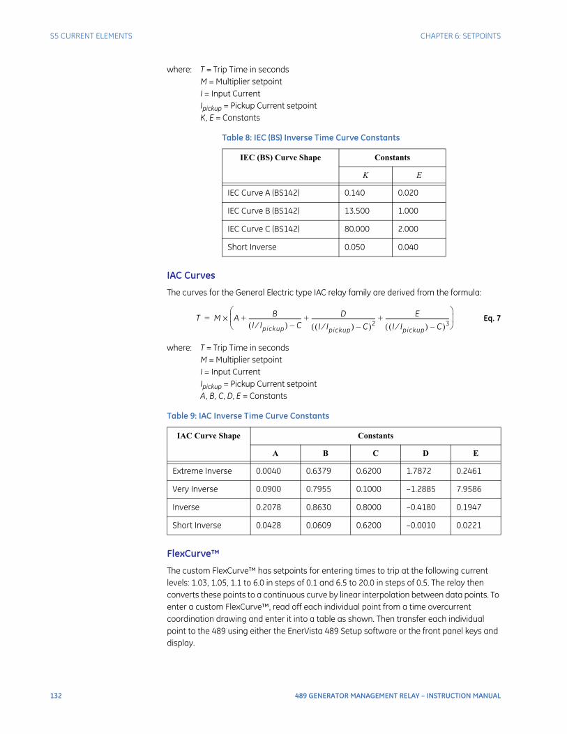
132 489 GENERATOR MANAGEMENT RELAY – INSTRUCTION MANUAL
S5 CURRENT ELEMENTS CHAPTER 6: SETPOINTS
where: T = Trip Time in secondsM = Multiplier setpointI = Input CurrentIpickup = Pickup Current setpointK, E = Constants
IAC Curves
The curves for the General Electric type IAC relay family are derived from the formula:
Eq. 7
where: T = Trip Time in secondsM = Multiplier setpointI = Input CurrentIpickup = Pickup Current setpointA, B, C, D, E = Constants
FlexCurve™
The custom FlexCurve™ has setpoints for entering times to trip at the following current levels: 1.03, 1.05, 1.1 to 6.0 in steps of 0.1 and 6.5 to 20.0 in steps of 0.5. The relay then converts these points to a continuous curve by linear interpolation between data points. To enter a custom FlexCurve™, read off each individual point from a time overcurrent coordination drawing and enter it into a table as shown. Then transfer each individual point to the 489 using either the EnerVista 489 Setup software or the front panel keys and display.
Table 8: IEC (BS) Inverse Time Curve Constants
IEC (BS) Curve Shape Constants
K E
IEC Curve A (BS142) 0.140 0.020
IEC Curve B (BS142) 13.500 1.000
IEC Curve C (BS142) 80.000 2.000
Short Inverse 0.050 0.040
Table 9: IAC Inverse Time Curve Constants
IAC Curve Shape Constants
A B C D E
Extreme Inverse 0.0040 0.6379 0.6200 1.7872 0.2461
Very Inverse 0.0900 0.7955 0.1000 –1.2885 7.9586
Inverse 0.2078 0.8630 0.8000 –0.4180 0.1947
Short Inverse 0.0428 0.0609 0.6200 –0.0010 0.0221
T M A BI Ipickup⁄( ) C–
------------------------------------ D
I Ipickup⁄( ) C–( )2------------------------------------------- E
I Ipickup⁄( ) C–( )3-------------------------------------------+ + +
×=
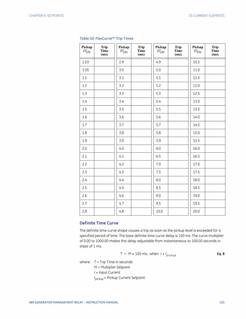
CHAPTER 6: SETPOINTS S5 CURRENT ELEMENTS
489 GENERATOR MANAGEMENT RELAY – INSTRUCTION MANUAL 133
Definite Time Curve
The definite time curve shape causes a trip as soon as the pickup level is exceeded for a specified period of time. The base definite time curve delay is 100 ms. The curve multiplier of 0.00 to 1000.00 makes this delay adjustable from instantaneous to 100.00 seconds in steps of 1 ms.
Eq. 8
where: T = Trip Time in secondsM = Multiplier SetpointI = Input CurrentIpickup = Pickup Current Setpoint
Table 10: FlexCurve™ Trip Times
PickupI/Ipkp
Trip Time(ms)
PickupI/Ipkp
Trip Time(ms)
PickupI/Ipkp
Trip Time(ms)
PickupI/Ipkp
Trip Time(ms)
1.03 2.9 4.9 10.5
1.05 3.0 5.0 11.0
1.1 3.1 5.1 11.5
1.2 3.2 5.2 12.0
1.3 3.3 5.3 12.5
1.4 3.4 5.4 13.0
1.5 3.5 5.5 13.5
1.6 3.6 5.6 14.0
1.7 3.7 5.7 14.5
1.8 3.8 5.8 15.0
1.9 3.9 5.9 15.5
2.0 4.0 6.0 16.0
2.1 4.1 6.5 16.5
2.2 4.2 7.0 17.0
2.3 4.3 7.5 17.5
2.4 4.4 8.0 18.0
2.5 4.5 8.5 18.5
2.6 4.6 9.0 19.0
2.7 4.7 9.5 19.5
2.8 4.8 10.0 20.0
T M 100 ms, when I Ipickup>×=
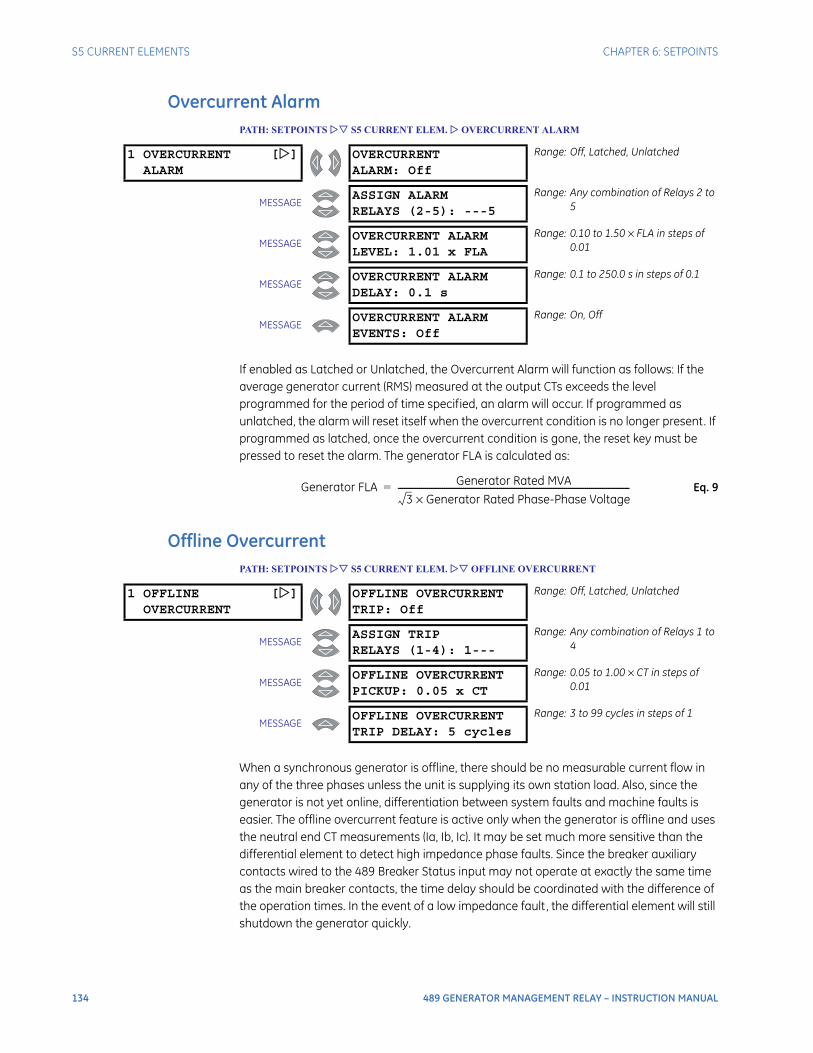
134 489 GENERATOR MANAGEMENT RELAY – INSTRUCTION MANUAL
S5 CURRENT ELEMENTS CHAPTER 6: SETPOINTS
Overcurrent AlarmPATH: SETPOINTS S5 CURRENT ELEM. OVERCURRENT ALARM
If enabled as Latched or Unlatched, the Overcurrent Alarm will function as follows: If the average generator current (RMS) measured at the output CTs exceeds the level programmed for the period of time specified, an alarm will occur. If programmed as unlatched, the alarm will reset itself when the overcurrent condition is no longer present. If programmed as latched, once the overcurrent condition is gone, the reset key must be pressed to reset the alarm. The generator FLA is calculated as:
Eq. 9
Offline OvercurrentPATH: SETPOINTS S5 CURRENT ELEM. OFFLINE OVERCURRENT
When a synchronous generator is offline, there should be no measurable current flow in any of the three phases unless the unit is supplying its own station load. Also, since the generator is not yet online, differentiation between system faults and machine faults is easier. The offline overcurrent feature is active only when the generator is offline and uses the neutral end CT measurements (Ia, Ib, Ic). It may be set much more sensitive than the differential element to detect high impedance phase faults. Since the breaker auxiliary contacts wired to the 489 Breaker Status input may not operate at exactly the same time as the main breaker contacts, the time delay should be coordinated with the difference of the operation times. In the event of a low impedance fault, the differential element will still shutdown the generator quickly.
1 OVERCURRENT []ALARM
OVERCURRENTALARM: Off
Range: Off, Latched, Unlatched
MESSAGEASSIGN ALARMRELAYS (2-5): ---5
Range: Any combination of Relays 2 to 5
MESSAGEOVERCURRENT ALARMLEVEL: 1.01 x FLA
Range: 0.10 to 1.50 × FLA in steps of 0.01
MESSAGEOVERCURRENT ALARMDELAY: 0.1 s
Range: 0.1 to 250.0 s in steps of 0.1
MESSAGEOVERCURRENT ALARMEVENTS: Off
Range: On, Off
Generator FLA Generator Rated MVA
3 Generator Rated Phase-Phase Voltage×--------------------------------------------------------------------------------------------------------------=
1 OFFLINE []OVERCURRENT
OFFLINE OVERCURRENTTRIP: Off
Range: Off, Latched, Unlatched
MESSAGEASSIGN TRIPRELAYS (1-4): 1---
Range: Any combination of Relays 1 to 4
MESSAGEOFFLINE OVERCURRENTPICKUP: 0.05 x CT
Range: 0.05 to 1.00 × CT in steps of 0.01
MESSAGEOFFLINE OVERCURRENTTRIP DELAY: 5 cycles
Range: 3 to 99 cycles in steps of 1
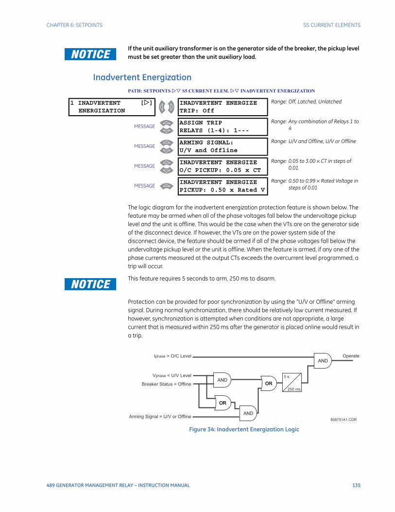
CHAPTER 6: SETPOINTS S5 CURRENT ELEMENTS
489 GENERATOR MANAGEMENT RELAY – INSTRUCTION MANUAL 135
If the unit auxiliary transformer is on the generator side of the breaker, the pickup level must be set greater than the unit auxiliary load.
Inadvertent EnergizationPATH: SETPOINTS S5 CURRENT ELEM. INADVERTENT ENERGIZATION
The logic diagram for the inadvertent energization protection feature is shown below. The feature may be armed when all of the phase voltages fall below the undervoltage pickup level and the unit is offline. This would be the case when the VTs are on the generator side of the disconnect device. If however, the VTs are on the power system side of the disconnect device, the feature should be armed if all of the phase voltages fall below the undervoltage pickup level or the unit is offline. When the feature is armed, if any one of the phase currents measured at the output CTs exceeds the overcurrent level programmed, a trip will occur.
This feature requires 5 seconds to arm, 250 ms to disarm.
Protection can be provided for poor synchronization by using the “U/V or Offline” arming signal. During normal synchronization, there should be relatively low current measured. If however, synchronization is attempted when conditions are not appropriate, a large current that is measured within 250 ms after the generator is placed online would result in a trip.
Figure 34: Inadvertent Energization Logic
1 INADVERTENT []ENERGIZATION
INADVERTENT ENERGIZETRIP: Off
Range: Off, Latched, Unlatched
MESSAGEASSIGN TRIPRELAYS (1-4): 1---
Range: Any combination of Relays 1 to 4
MESSAGEARMING SIGNAL:U/V and Offline
Range: U/V and Offline, U/V or Offline
MESSAGEINADVERTENT ENERGIZEO/C PICKUP: 0.05 x CT
Range: 0.05 to 3.00 × CT in steps of 0.01
MESSAGEINADVERTENT ENERGIZEPICKUP: 0.50 x Rated V
Range: 0.50 to 0.99 × Rated Voltage in steps of 0.01
AND
AND
AND
OROR
OROR
V < U/V Levelphase
I > O/C Levelphase Operate
Breaker Status = Offline
Arming Signal = U/V or Offline
5 s
250 ms
808731A1.CDR
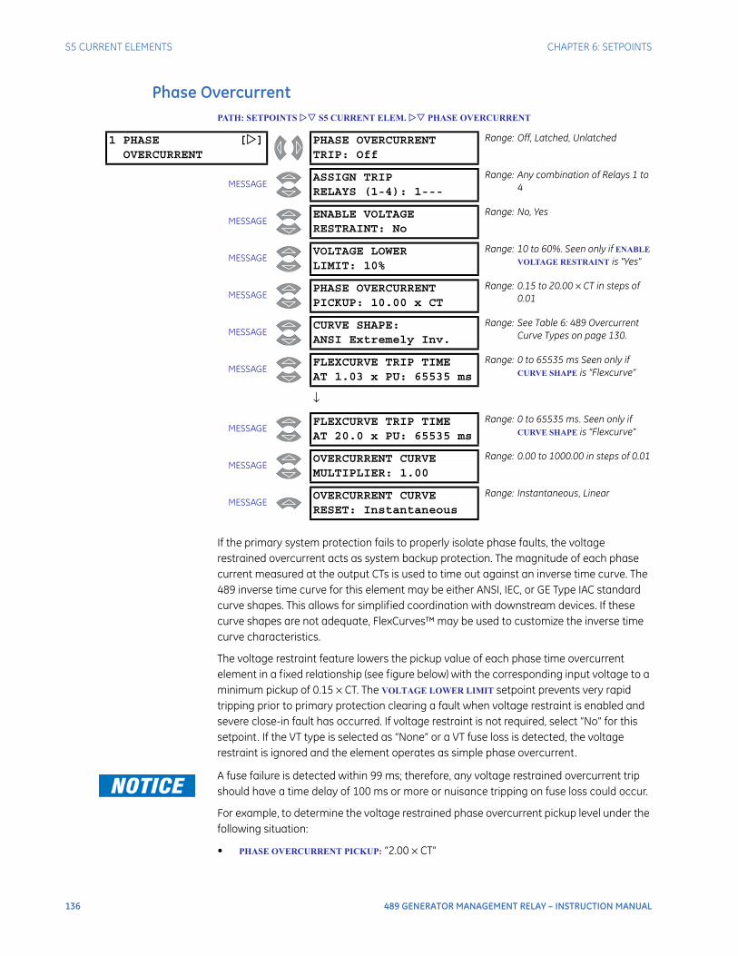
136 489 GENERATOR MANAGEMENT RELAY – INSTRUCTION MANUAL
S5 CURRENT ELEMENTS CHAPTER 6: SETPOINTS
Phase OvercurrentPATH: SETPOINTS S5 CURRENT ELEM. PHASE OVERCURRENT
If the primary system protection fails to properly isolate phase faults, the voltage restrained overcurrent acts as system backup protection. The magnitude of each phase current measured at the output CTs is used to time out against an inverse time curve. The 489 inverse time curve for this element may be either ANSI, IEC, or GE Type IAC standard curve shapes. This allows for simplified coordination with downstream devices. If these curve shapes are not adequate, FlexCurves™ may be used to customize the inverse time curve characteristics.
The voltage restraint feature lowers the pickup value of each phase time overcurrent element in a fixed relationship (see figure below) with the corresponding input voltage to a minimum pickup of 0.15 × CT. The VOLTAGE LOWER LIMIT setpoint prevents very rapid tripping prior to primary protection clearing a fault when voltage restraint is enabled and severe close-in fault has occurred. If voltage restraint is not required, select “No” for this setpoint. If the VT type is selected as “None” or a VT fuse loss is detected, the voltage restraint is ignored and the element operates as simple phase overcurrent.
A fuse failure is detected within 99 ms; therefore, any voltage restrained overcurrent trip should have a time delay of 100 ms or more or nuisance tripping on fuse loss could occur.
For example, to determine the voltage restrained phase overcurrent pickup level under the following situation:
• PHASE OVERCURRENT PICKUP: “2.00 × CT”
1 PHASE []OVERCURRENT
PHASE OVERCURRENTTRIP: Off
Range: Off, Latched, Unlatched
MESSAGEASSIGN TRIPRELAYS (1-4): 1---
Range: Any combination of Relays 1 to 4
MESSAGEENABLE VOLTAGERESTRAINT: No
Range: No, Yes
MESSAGEVOLTAGE LOWERLIMIT: 10%
Range: 10 to 60%. Seen only if ENABLE
VOLTAGE RESTRAINT is "Yes"
MESSAGEPHASE OVERCURRENTPICKUP: 10.00 x CT
Range: 0.15 to 20.00 × CT in steps of 0.01
MESSAGECURVE SHAPE:ANSI Extremely Inv.
Range: See Table 6: 489 Overcurrent Curve Types on page 130.
MESSAGEFLEXCURVE TRIP TIMEAT 1.03 x PU: 65535 ms
Range: 0 to 65535 ms Seen only if CURVE SHAPE is “Flexcurve”
↓
MESSAGEFLEXCURVE TRIP TIMEAT 20.0 x PU: 65535 ms
Range: 0 to 65535 ms. Seen only if CURVE SHAPE is “Flexcurve”
MESSAGEOVERCURRENT CURVEMULTIPLIER: 1.00
Range: 0.00 to 1000.00 in steps of 0.01
MESSAGEOVERCURRENT CURVERESET: Instantaneous
Range: Instantaneous, Linear
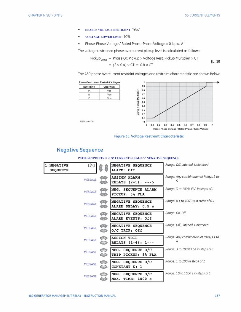
CHAPTER 6: SETPOINTS S5 CURRENT ELEMENTS
489 GENERATOR MANAGEMENT RELAY – INSTRUCTION MANUAL 137
• ENABLE VOLTAGE RESTRAINT: “Yes”
• VOLTAGE LOWER LIMIT: 10%
• Phase-Phase Voltage / Rated Phase-Phase Voltage = 0.4 p.u. V
The voltage restrained phase overcurrent pickup level is calculated as follows:
Eq. 10
The 489 phase overcurrent restraint voltages and restraint characteristic are shown below.
Figure 35: Voltage Restraint Characteristic
Negative SequencePATH: SETPOINTS S5 CURRENT ELEM. NEGATIVE SEQUENCE
Pickupvrest Phase OC Pickup Voltage Rest. Pickup Multiplier CT××=
2 0.4×( ) CT×= 0.8 CT×=
808792A4.CDR
Phase-Phase Voltage / Rated Phase-Phase Voltage
Cu
rve
Pic
ku
pM
ult
iplier
0
0 0.1 0.2 0.3 0.4 0.5 0.6 0.7 0.8 0.9 1
0.1
0.2
0.4
0.5
0.6
0.7
0.8
0.9
1
0.3
CURRENT VOLTAGE
IA Vab
IB Vbc
IC Vca
Phase Overcurrent Restraint Voltages:
1 NEGATIVE []SEQUENCE
NEGATIVE SEQUENCEALARM: Off
Range: Off, Latched, Unlatched
MESSAGEASSIGN ALARMRELAYS (2-5): ---5
Range: Any combination of Relays 2 to 5
MESSAGENEG. SEQUENCE ALARMPICKUP: 3% FLA
Range: 3 to 100% FLA in steps of 1
MESSAGENEGATIVE SEQUENCEALARM DELAY: 0.5 s
Range: 0.1 to 100.0 s in steps of 0.1
MESSAGENEGATIVE SEQUENCEALARM EVENTS: Off
Range: On, Off
MESSAGENEGATIVE SEQUENCEO/C TRIP: Off
Range: Off, Latched, Unlatched
MESSAGEASSIGN TRIPRELAYS (1-4): 1---
Range: Any combination of Relays 1 to 4
MESSAGENEG. SEQUENCE O/CTRIP PICKUP: 8% FLA
Range: 3 to 100% FLA in steps of 1
MESSAGENEG. SEQUENCE O/CCONSTANT K: 1
Range: 1 to 100 in steps of 1
MESSAGENEG. SEQUENCE O/CMAX. TIME: 1000 s
Range: 10 to 1000 s in steps of 1
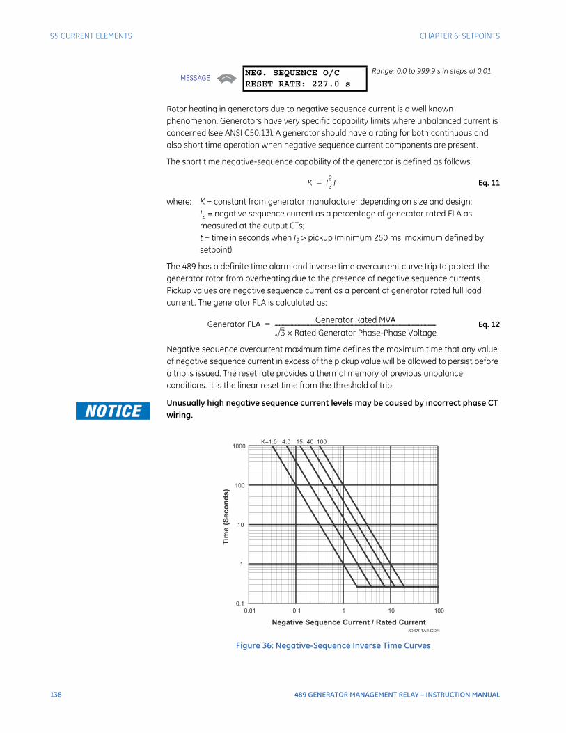
138 489 GENERATOR MANAGEMENT RELAY – INSTRUCTION MANUAL
S5 CURRENT ELEMENTS CHAPTER 6: SETPOINTS
Rotor heating in generators due to negative sequence current is a well known phenomenon. Generators have very specific capability limits where unbalanced current is concerned (see ANSI C50.13). A generator should have a rating for both continuous and also short time operation when negative sequence current components are present.
The short time negative-sequence capability of the generator is defined as follows:
Eq. 11
where: K = constant from generator manufacturer depending on size and design;I2 = negative sequence current as a percentage of generator rated FLA as measured at the output CTs;t = time in seconds when I2 > pickup (minimum 250 ms, maximum defined by setpoint).
The 489 has a definite time alarm and inverse time overcurrent curve trip to protect the generator rotor from overheating due to the presence of negative sequence currents. Pickup values are negative sequence current as a percent of generator rated full load current. The generator FLA is calculated as:
Eq. 12
Negative sequence overcurrent maximum time defines the maximum time that any value of negative sequence current in excess of the pickup value will be allowed to persist before a trip is issued. The reset rate provides a thermal memory of previous unbalance conditions. It is the linear reset time from the threshold of trip.
Unusually high negative sequence current levels may be caused by incorrect phase CT wiring.
Figure 36: Negative-Sequence Inverse Time Curves
MESSAGENEG. SEQUENCE O/CRESET RATE: 227.0 s
Range: 0.0 to 999.9 s in steps of 0.01
K I22T=
Generator FLA Generator Rated MVA
3 Rated Generator Phase-Phase Voltage×--------------------------------------------------------------------------------------------------------------=
808791A2.CDR
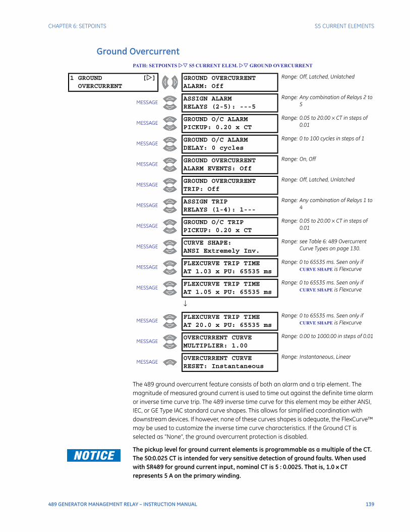
CHAPTER 6: SETPOINTS S5 CURRENT ELEMENTS
489 GENERATOR MANAGEMENT RELAY – INSTRUCTION MANUAL 139
Ground OvercurrentPATH: SETPOINTS S5 CURRENT ELEM. GROUND OVERCURRENT
The 489 ground overcurrent feature consists of both an alarm and a trip element. The magnitude of measured ground current is used to time out against the definite time alarm or inverse time curve trip. The 489 inverse time curve for this element may be either ANSI, IEC, or GE Type IAC standard curve shapes. This allows for simplified coordination with downstream devices. If however, none of these curves shapes is adequate, the FlexCurve™ may be used to customize the inverse time curve characteristics. If the Ground CT is selected as “None”, the ground overcurrent protection is disabled.
The pickup level for ground current elements is programmable as a multiple of the CT. The 50:0.025 CT is intended for very sensitive detection of ground faults. When used with SR489 for ground current input, nominal CT is 5 : 0.0025. That is, 1.0 x CT represents 5 A on the primary winding.
1 GROUND []OVERCURRENT
GROUND OVERCURRENTALARM: Off
Range: Off, Latched, Unlatched
MESSAGEASSIGN ALARMRELAYS (2-5): ---5
Range: Any combination of Relays 2 to 5
MESSAGEGROUND O/C ALARMPICKUP: 0.20 x CT
Range: 0.05 to 20.00 × CT in steps of 0.01
MESSAGEGROUND O/C ALARMDELAY: 0 cycles
Range: 0 to 100 cycles in steps of 1
MESSAGEGROUND OVERCURRENTALARM EVENTS: Off
Range: On, Off
MESSAGEGROUND OVERCURRENTTRIP: Off
Range: Off, Latched, Unlatched
MESSAGEASSIGN TRIPRELAYS (1-4): 1---
Range: Any combination of Relays 1 to 4
MESSAGEGROUND O/C TRIPPICKUP: 0.20 x CT
Range: 0.05 to 20.00 × CT in steps of 0.01
MESSAGECURVE SHAPE:ANSI Extremely Inv.
Range: see Table 6: 489 Overcurrent Curve Types on page 130.
MESSAGEFLEXCURVE TRIP TIMEAT 1.03 x PU: 65535 ms
Range: 0 to 65535 ms. Seen only if CURVE SHAPE is Flexcurve
MESSAGEFLEXCURVE TRIP TIMEAT 1.05 x PU: 65535 ms
Range: 0 to 65535 ms. Seen only if CURVE SHAPE is Flexcurve
↓
MESSAGEFLEXCURVE TRIP TIMEAT 20.0 x PU: 65535 ms
Range: 0 to 65535 ms. Seen only if CURVE SHAPE is Flexcurve
MESSAGEOVERCURRENT CURVEMULTIPLIER: 1.00
Range: 0.00 to 1000.00 in steps of 0.01
MESSAGEOVERCURRENT CURVERESET: Instantaneous
Range: Instantaneous, Linear
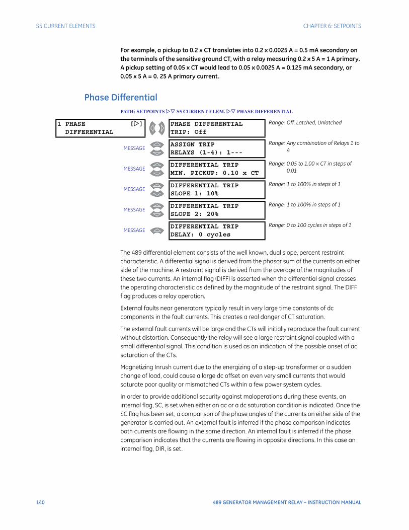
140 489 GENERATOR MANAGEMENT RELAY – INSTRUCTION MANUAL
S5 CURRENT ELEMENTS CHAPTER 6: SETPOINTS
For example, a pickup to 0.2 x CT translates into 0.2 x 0.0025 A = 0.5 mA secondary on the terminals of the sensitive ground CT, with a relay measuring 0.2 x 5 A = 1 A primary. A pickup setting of 0.05 x CT would lead to 0.05 x 0.0025 A = 0.125 mA secondary, or 0.05 x 5 A = 0. 25 A primary current.
Phase DifferentialPATH: SETPOINTS S5 CURRENT ELEM. PHASE DIFFERENTIAL
The 489 differential element consists of the well known, dual slope, percent restraint characteristic. A differential signal is derived from the phasor sum of the currents on either side of the machine. A restraint signal is derived from the average of the magnitudes of these two currents. An internal flag (DIFF) is asserted when the differential signal crosses the operating characteristic as defined by the magnitude of the restraint signal. The DIFF flag produces a relay operation.
External faults near generators typically result in very large time constants of dc components in the fault currents. This creates a real danger of CT saturation.
The external fault currents will be large and the CTs will initially reproduce the fault current without distortion. Consequently the relay will see a large restraint signal coupled with a small differential signal. This condition is used as an indication of the possible onset of ac saturation of the CTs.
Magnetizing Inrush current due to the energizing of a step-up transformer or a sudden change of load, could cause a large dc offset on even very small currents that would saturate poor quality or mismatched CTs within a few power system cycles.
In order to provide additional security against maloperations during these events, an internal flag, SC, is set when either an ac or a dc saturation condition is indicated. Once the SC flag has been set, a comparison of the phase angles of the currents on either side of the generator is carried out. An external fault is inferred if the phase comparison indicates both currents are flowing in the same direction. An internal fault is inferred if the phase comparison indicates that the currents are flowing in opposite directions. In this case an internal flag, DIR, is set.
1 PHASE []DIFFERENTIAL
PHASE DIFFERENTIALTRIP: Off
Range: Off, Latched, Unlatched
MESSAGEASSIGN TRIPRELAYS (1-4): 1---
Range: Any combination of Relays 1 to 4
MESSAGEDIFFERENTIAL TRIPMIN. PICKUP: 0.10 x CT
Range: 0.05 to 1.00 × CT in steps of 0.01
MESSAGEDIFFERENTIAL TRIPSLOPE 1: 10%
Range: 1 to 100% in steps of 1
MESSAGEDIFFERENTIAL TRIPSLOPE 2: 20%
Range: 1 to 100% in steps of 1
MESSAGEDIFFERENTIAL TRIPDELAY: 0 cycles
Range: 0 to 100 cycles in steps of 1

CHAPTER 6: SETPOINTS S5 CURRENT ELEMENTS
489 GENERATOR MANAGEMENT RELAY – INSTRUCTION MANUAL 141
If the SC flag is not set, then the relay will operate for a DIFF flag alone. If the SC flag is set then the directional flag supervises the differential flag. The requirement for both the DIFF flag and the DIR flag during the period where CT saturation is likely therefore enhances the security of the scheme.
The differential element for phase A will operate when:
Eq. 13
where the following hold:
Eq. 14
Eq. 15
Eq. 16
IA = phase current measured at the output CT Eq. 17
Ia = phase current measured at the neutral end CT Eq. 18
Differential elements for phase B and phase C operate in the same manner.
Figure 37: Differential Elements
Ground DirectionalPATH: SETPOINTS S5 CURRENT ELEM. GROUND DIRECTIONAL
Ioperate k Irestraint×>
Ioperate IA Ia+ operate current= =
IrestraintIA Ia+
2-------------------- restraint current= =
k characteristic slope of the differential element in percent=k Slope1 if IR 2 CT×<= ; k Slope2 if IR 2 CT×≥=
OPERATE
REGION
I (multiples of CT)RESTRAINT
I(m
ult
iple
so
fC
T)
OP
ER
AT
E
Slope 2 = 20%
808790A2.CDR
Slope 1 = 10%Minimum Pickup = 0.10 x CT
1
0.9
0.8
0.7
0.6
0.5
0.4
0.3
0.2
0.1
0 0.5 1 1.5 2 2.5 3 3.5 4 4.5 5
0
1 GROUND []DIRECTIONAL
SUPERVISE WITHDIGITAL INPUTS: Yes
Range: Yes, No.
MESSAGEGROUND DIRECTIONALMTA: 0°
Range: 0°, 90°, 180°, 270°MTA = Maximum Torque Angle
MESSAGEGROUND DIRECTIONALALARM: Off
Range: Off, Latched, Unlatched
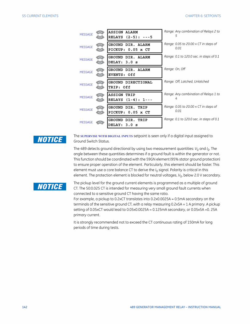
142 489 GENERATOR MANAGEMENT RELAY – INSTRUCTION MANUAL
S5 CURRENT ELEMENTS CHAPTER 6: SETPOINTS
The SUPERVISE WITH DIGITAL INPUTS setpoint is seen only if a digital input assigned to Ground Switch Status.
The 489 detects ground directional by using two measurement quantities: V0 and I0. The angle between these quantities determines if a ground fault is within the generator or not. This function should be coordinated with the 59GN element (95% stator ground protection) to ensure proper operation of the element. Particularly, this element should be faster. This element must use a core balance CT to derive the I0 signal. Polarity is critical in this element. The protection element is blocked for neutral voltages, V0, below 2.0 V secondary.
The pickup level for the ground current elements is programmed as a multiple of ground CT. The 50:0.025 CT is intended for measuring very small ground fault currents when connected to a sensitive ground CT having the same ratio. For example, a pickup to 0.2xCT translates into 0.2x0.0025A = 0.5mA secondary on the terminals of the sensitive ground CT, with a relay measuring 0.2x5A = 1 A primary. A pickup setting of 0.05xCT would lead to 0.05x0.0025A = 0.125mA secondary, or 0.05x5A =0. 25A primary current.
It is strongly recommended not to exceed the CT continuous rating of 150mA for long periods of time during tests.
MESSAGEASSIGN ALARMRELAYS (2-5): ---5
Range: Any combination of Relays 2 to 5
MESSAGEGROUND DIR. ALARMPICKUP: 0.05 x CT
Range: 0.05 to 20.00 × CT in steps of 0.01
MESSAGEGROUND DIR. ALARMDELAY: 3.0 s
Range: 0.1 to 120.0 sec. in steps of 0.1
MESSAGEGROUND DIR. ALARMEVENTS: Off
Range: On, Off
MESSAGEGROUND DIRECTIONALTRIP: Off
Range: Off, Latched, Unlatched
MESSAGEASSIGN TRIPRELAYS (1-4): 1---
Range: Any combination of Relays 1 to 4
MESSAGEGROUND DIR. TRIPPICKUP: 0.05 x CT
Range: 0.05 to 20.00 × CT in steps of 0.01
MESSAGEGROUND DIR. TRIPDELAY: 3.0 s
Range: 0.1 to 120.0 sec. in steps of 0.1
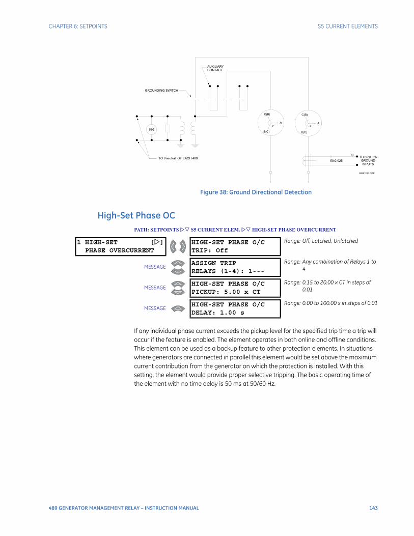
CHAPTER 6: SETPOINTS S5 CURRENT ELEMENTS
489 GENERATOR MANAGEMENT RELAY – INSTRUCTION MANUAL 143
Figure 38: Ground Directional Detection
High-Set Phase OCPATH: SETPOINTS S5 CURRENT ELEM. HIGH-SET PHASE OVERCURRENT
If any individual phase current exceeds the pickup level for the specified trip time a trip will occur if the feature is enabled. The element operates in both online and offline conditions. This element can be used as a backup feature to other protection elements. In situations where generators are connected in parallel this element would be set above the maximum current contribution from the generator on which the protection is installed. With this setting, the element would provide proper selective tripping. The basic operating time of the element with no time delay is 50 ms at 50/60 Hz.
59G
A A
C(B) C(B)
B(C) B(C)
TO 50:0.025GROUNDINPUTS
50:0.025
I0TO Vneutral OF EACH 489
AUXILIARYCONTACT
GROUNDING SWITCH
808812A3.CDR
1 HIGH-SET []PHASE OVERCURRENT
HIGH-SET PHASE O/CTRIP: Off
Range: Off, Latched, Unlatched
MESSAGEASSIGN TRIPRELAYS (1-4): 1---
Range: Any combination of Relays 1 to 4
MESSAGEHIGH-SET PHASE O/CPICKUP: 5.00 x CT
Range: 0.15 to 20.00 x CT in steps of 0.01
MESSAGEHIGH-SET PHASE O/CDELAY: 1.00 s
Range: 0.00 to 100.00 s in steps of 0.01
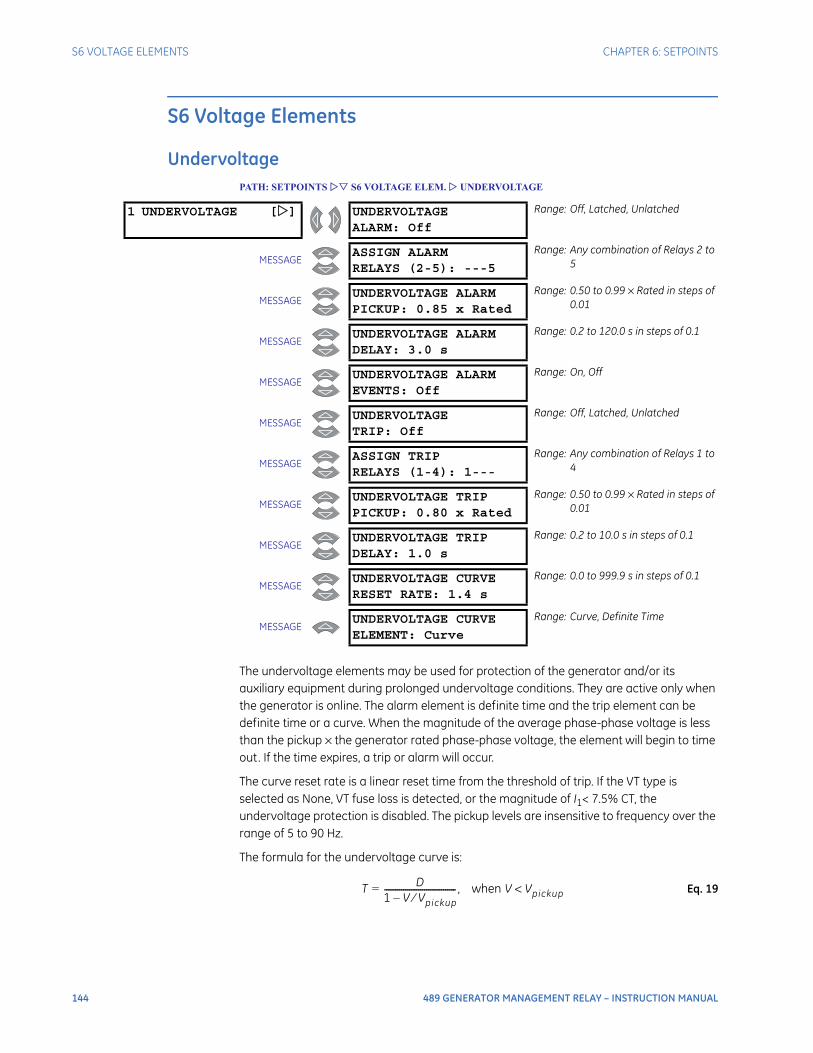
144 489 GENERATOR MANAGEMENT RELAY – INSTRUCTION MANUAL
S6 VOLTAGE ELEMENTS CHAPTER 6: SETPOINTS
S6 Voltage Elements
UndervoltagePATH: SETPOINTS S6 VOLTAGE ELEM. UNDERVOLTAGE
The undervoltage elements may be used for protection of the generator and/or its auxiliary equipment during prolonged undervoltage conditions. They are active only when the generator is online. The alarm element is definite time and the trip element can be definite time or a curve. When the magnitude of the average phase-phase voltage is less than the pickup × the generator rated phase-phase voltage, the element will begin to time out. If the time expires, a trip or alarm will occur.
The curve reset rate is a linear reset time from the threshold of trip. If the VT type is selected as None, VT fuse loss is detected, or the magnitude of I1< 7.5% CT, the undervoltage protection is disabled. The pickup levels are insensitive to frequency over the range of 5 to 90 Hz.
The formula for the undervoltage curve is:
Eq. 19
1 UNDERVOLTAGE [] UNDERVOLTAGEALARM: Off
Range: Off, Latched, Unlatched
MESSAGEASSIGN ALARMRELAYS (2-5): ---5
Range: Any combination of Relays 2 to 5
MESSAGEUNDERVOLTAGE ALARMPICKUP: 0.85 x Rated
Range: 0.50 to 0.99 × Rated in steps of 0.01
MESSAGEUNDERVOLTAGE ALARMDELAY: 3.0 s
Range: 0.2 to 120.0 s in steps of 0.1
MESSAGEUNDERVOLTAGE ALARMEVENTS: Off
Range: On, Off
MESSAGEUNDERVOLTAGETRIP: Off
Range: Off, Latched, Unlatched
MESSAGEASSIGN TRIPRELAYS (1-4): 1---
Range: Any combination of Relays 1 to 4
MESSAGEUNDERVOLTAGE TRIPPICKUP: 0.80 x Rated
Range: 0.50 to 0.99 × Rated in steps of 0.01
MESSAGEUNDERVOLTAGE TRIPDELAY: 1.0 s
Range: 0.2 to 10.0 s in steps of 0.1
MESSAGEUNDERVOLTAGE CURVERESET RATE: 1.4 s
Range: 0.0 to 999.9 s in steps of 0.1
MESSAGEUNDERVOLTAGE CURVEELEMENT: Curve
Range: Curve, Definite Time
T D1 V Vpickup⁄–----------------------------------= , when V Vpickup<
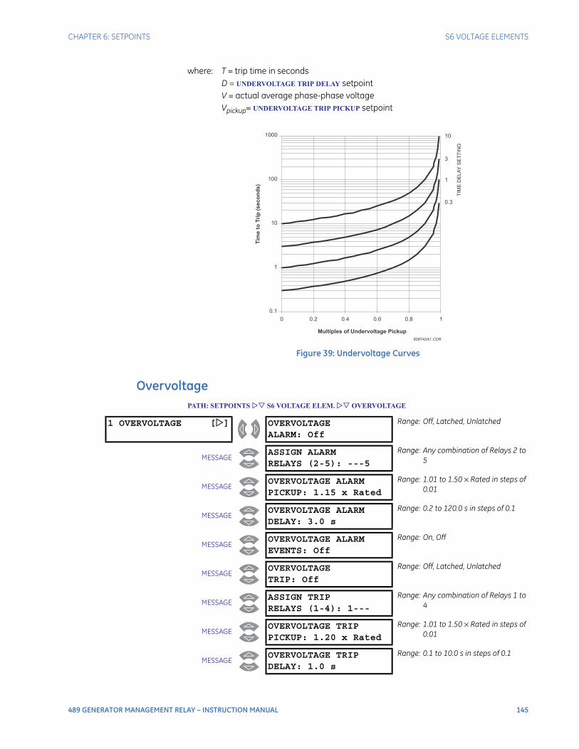
CHAPTER 6: SETPOINTS S6 VOLTAGE ELEMENTS
489 GENERATOR MANAGEMENT RELAY – INSTRUCTION MANUAL 145
where: T = trip time in secondsD = UNDERVOLTAGE TRIP DELAY setpointV = actual average phase-phase voltageVpickup= UNDERVOLTAGE TRIP PICKUP setpoint
Figure 39: Undervoltage Curves
OvervoltagePATH: SETPOINTS S6 VOLTAGE ELEM. OVERVOLTAGE
808742A1.CDR
0.1
1
10
100
1000
0 0.2 0.4 0.6 0.8 1
Multiples of Undervoltage Pickup
10
3
1
0.3
TIM
ED
ELA
YS
ET
TIN
G
Tim
eto
Trip
(se
co
nd
s)
1 OVERVOLTAGE [] OVERVOLTAGEALARM: Off
Range: Off, Latched, Unlatched
MESSAGEASSIGN ALARMRELAYS (2-5): ---5
Range: Any combination of Relays 2 to 5
MESSAGEOVERVOLTAGE ALARMPICKUP: 1.15 x Rated
Range: 1.01 to 1.50 × Rated in steps of 0.01
MESSAGEOVERVOLTAGE ALARMDELAY: 3.0 s
Range: 0.2 to 120.0 s in steps of 0.1
MESSAGEOVERVOLTAGE ALARMEVENTS: Off
Range: On, Off
MESSAGEOVERVOLTAGETRIP: Off
Range: Off, Latched, Unlatched
MESSAGEASSIGN TRIPRELAYS (1-4): 1---
Range: Any combination of Relays 1 to 4
MESSAGEOVERVOLTAGE TRIPPICKUP: 1.20 x Rated
Range: 1.01 to 1.50 × Rated in steps of 0.01
MESSAGEOVERVOLTAGE TRIPDELAY: 1.0 s
Range: 0.1 to 10.0 s in steps of 0.1
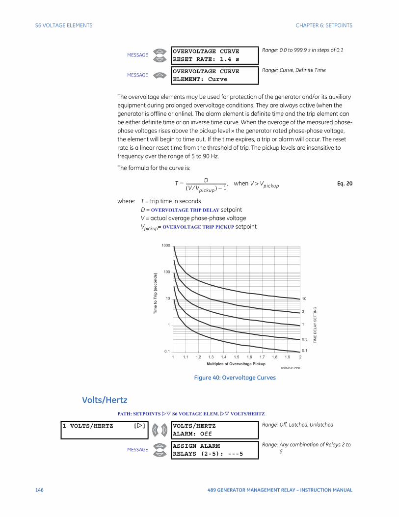
146 489 GENERATOR MANAGEMENT RELAY – INSTRUCTION MANUAL
S6 VOLTAGE ELEMENTS CHAPTER 6: SETPOINTS
The overvoltage elements may be used for protection of the generator and/or its auxiliary equipment during prolonged overvoltage conditions. They are always active (when the generator is offline or online). The alarm element is definite time and the trip element can be either definite time or an inverse time curve. When the average of the measured phase-phase voltages rises above the pickup level x the generator rated phase-phase voltage, the element will begin to time out. If the time expires, a trip or alarm will occur. The reset rate is a linear reset time from the threshold of trip. The pickup levels are insensitive to frequency over the range of 5 to 90 Hz.
The formula for the curve is:
Eq. 20
where: T = trip time in secondsD = OVERVOLTAGE TRIP DELAY setpointV = actual average phase-phase voltageVpickup= OVERVOLTAGE TRIP PICKUP setpoint
Figure 40: Overvoltage Curves
Volts/HertzPATH: SETPOINTS S6 VOLTAGE ELEM. VOLTS/HERTZ
MESSAGEOVERVOLTAGE CURVERESET RATE: 1.4 s
Range: 0.0 to 999.9 s in steps of 0.1
MESSAGEOVERVOLTAGE CURVEELEMENT: Curve
Range: Curve, Definite Time
T DV Vpickup⁄( ) 1–
---------------------------------------= , when V Vpickup>
808741A1.CDR
0.1
1
10
100
1000
1 1.1 1.2 1.3 1.4 1.5 1.6 1.7 1.8 1.9 2
Multiples of Overvoltage Pickup
10
3
1
0.3
0.1
Tim
eto
Trip
(se
co
nd
s)
TIM
ED
ELA
YS
ET
TIN
G
1 VOLTS/HERTZ [] VOLTS/HERTZALARM: Off
Range: Off, Latched, Unlatched
MESSAGEASSIGN ALARMRELAYS (2-5): ---5
Range: Any combination of Relays 2 to 5
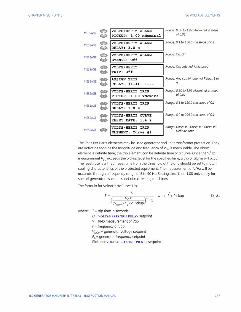
CHAPTER 6: SETPOINTS S6 VOLTAGE ELEMENTS
489 GENERATOR MANAGEMENT RELAY – INSTRUCTION MANUAL 147
The Volts Per Hertz elements may be used generator and unit transformer protection. They are active as soon as the magnitude and frequency of Vab is measurable. The alarm element is definite time; the trip element can be definite time or a curve. Once the V/Hz measurement Vab exceeds the pickup level for the specified time, a trip or alarm will occur. The reset rate is a linear reset time from the threshold of trip and should be set to match cooling characteristics of the protected equipment. The measurement of V/Hz will be accurate through a frequency range of 5 to 90 Hz. Settings less than 1.00 only apply for special generators such as short circuit testing machines.
The formula for Volts/Hertz Curve 1 is:
Eq. 21
where: T = trip time in secondsD = VOLTS/HERTZ TRIP DELAY setpointV = RMS measurement of VabF = frequency of VabVNOM = generator voltage setpointFS = generator frequency setpointPickup = VOLTS/HERTZ TRIP PICKUP setpoint
MESSAGEVOLTS/HERTZ ALARMPICKUP: 1.00 xNominal
Range: 0.50 to 1.99 ×Nominal in steps of 0.01
MESSAGEVOLTS/HERTZ ALARMDELAY: 3.0 s
Range: 0.1 to 150.0 s in steps of 0.1
MESSAGEVOLTS/HERTZ ALARMEVENTS: Off
Range: On, Off
MESSAGEVOLTS/HERTZTRIP: Off
Range: Off, Latched, Unlatched
MESSAGEASSIGN TRIPRELAYS (1-4): 1---
Range: Any combination of Relays 1 to 4
MESSAGEVOLTS/HERTZ TRIPPICKUP: 1.00 xNominal
Range: 0.50 to 1.99 ×Nominal in steps of 0.01
MESSAGEVOLTS/HERTZ TRIPDELAY: 1.0 s
Range: 0.1 to 150.0 s in steps of 0.1
MESSAGEVOLTS/HERTZ CURVERESET RATE: 1.4 s
Range: 0.0 to 999.9 s in steps of 0.1
MESSAGEVOLTS/HERTZ TRIPELEMENT: Curve #1
Range: Curve #1, Curve #2, Curve #3, Definite Time
TD
V F⁄Vnom Fs⁄( ) Pickup×
-------------------------------------------------- 2
1–-------------------------------------------------------------------= , when V
F--- Pickup>
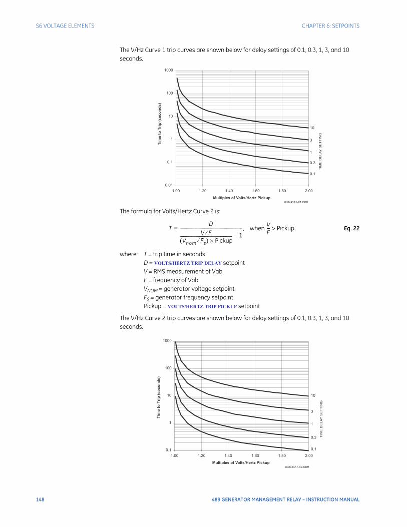
148 489 GENERATOR MANAGEMENT RELAY – INSTRUCTION MANUAL
S6 VOLTAGE ELEMENTS CHAPTER 6: SETPOINTS
The V/Hz Curve 1 trip curves are shown below for delay settings of 0.1, 0.3, 1, 3, and 10 seconds.
The formula for Volts/Hertz Curve 2 is:
Eq. 22
where: T = trip time in secondsD = VOLTS/HERTZ TRIP DELAY setpointV = RMS measurement of VabF = frequency of VabVNOM = generator voltage setpointFS = generator frequency setpointPickup = VOLTS/HERTZ TRIP PICKUP setpoint
The V/Hz Curve 2 trip curves are shown below for delay settings of 0.1, 0.3, 1, 3, and 10 seconds.
808743A1-X1.CDR
0.01
0.1
1
10
100
1000
1.00 1.20 1.40 1.60 1.80 2.00
Multiples of Volts/Hertz Pickup
10
3
1
0.3
TIM
ED
ELA
YS
ET
TIN
G
Tim
eto
Trip
(se
co
nd
s)
0.1
TD
V F⁄Vnom Fs⁄( ) Pickup×
-------------------------------------------------- 1–-----------------------------------------------------------= , when V
F--- Pickup>
808743A1-X2.CDR
0.1
1
10
100
1000
1.00 1.20 1.40 1.60 1.80 2.00
Multiples of Volts/Hertz Pickup
10
3
1
0.3 TIM
ED
ELA
YS
ET
TIN
G
0.1
Tim
eto
Trip
(se
co
nd
s)
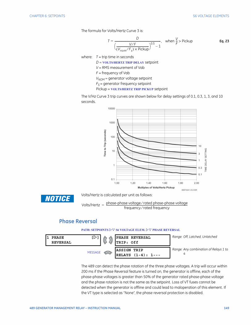
CHAPTER 6: SETPOINTS S6 VOLTAGE ELEMENTS
489 GENERATOR MANAGEMENT RELAY – INSTRUCTION MANUAL 149
The formula for Volts/Hertz Curve 3 is:
Eq. 23
where: T = trip time in secondsD = VOLTS/HERTZ TRIP DELAY setpointV = RMS measurement of VabF = frequency of VabVNOM = generator voltage setpointFS = generator frequency setpointPickup = VOLTS/HERTZ TRIP PICKUP setpoint
The V/Hz Curve 3 trip curves are shown below for delay settings of 0.1, 0.3, 1, 3, and 10 seconds.
Volts/Hertz is calculated per unit as follows:
Phase ReversalPATH: SETPOINTS S6 VOLTAGE ELEM. PHASE REVERSAL
The 489 can detect the phase rotation of the three phase voltages. A trip will occur within 200 ms if the Phase Reversal feature is turned on, the generator is offline, each of the phase-phase voltages is greater than 50% of the generator rated phase-phase voltage and the phase rotation is not the same as the setpoint. Loss of VT fuses cannot be detected when the generator is offline and could lead to maloperation of this element. If the VT type is selected as “None”, the phase reversal protection is disabled.
TD
V F⁄Vnom Fs⁄( ) Pickup×
-------------------------------------------------- 0.5
1–-----------------------------------------------------------------------= , when V
F--- Pickup>
808743A1-X3.CDR
0.1
1
10
100
1000
10000
1.00 1.20 1.40 1.60 1.80 2.00
Multiples of Voltz/Hertz Pickup
10
3
1
0.3
TIM
ED
EL
AY
SE
TT
ING
0.1
Tim
eto
Trip
(se
co
nd
s)
Volts/Hertz phase-phase voltage rated phase-phase voltage⁄frequency rated frequency⁄
-----------------------------------------------------------------------------------------------------------------------------=
1 PHASE []REVERSAL
PHASE REVERSALTRIP: Off
Range: Off, Latched, Unlatched
MESSAGEASSIGN TRIPRELAYS (1-4): 1---
Range: Any combination of Relays 1 to 4
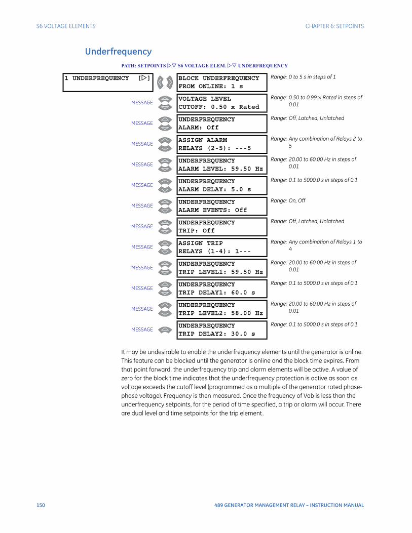
150 489 GENERATOR MANAGEMENT RELAY – INSTRUCTION MANUAL
S6 VOLTAGE ELEMENTS CHAPTER 6: SETPOINTS
UnderfrequencyPATH: SETPOINTS S6 VOLTAGE ELEM. UNDERFREQUENCY
It may be undesirable to enable the underfrequency elements until the generator is online. This feature can be blocked until the generator is online and the block time expires. From that point forward, the underfrequency trip and alarm elements will be active. A value of zero for the block time indicates that the underfrequency protection is active as soon as voltage exceeds the cutoff level (programmed as a multiple of the generator rated phase-phase voltage). Frequency is then measured. Once the frequency of Vab is less than the underfrequency setpoints, for the period of time specified, a trip or alarm will occur. There are dual level and time setpoints for the trip element.
1 UNDERFREQUENCY [] BLOCK UNDERFREQUENCYFROM ONLINE: 1 s
Range: 0 to 5 s in steps of 1
MESSAGEVOLTAGE LEVELCUTOFF: 0.50 x Rated
Range: 0.50 to 0.99 × Rated in steps of 0.01
MESSAGEUNDERFREQUENCYALARM: Off
Range: Off, Latched, Unlatched
MESSAGEASSIGN ALARMRELAYS (2-5): ---5
Range: Any combination of Relays 2 to 5
MESSAGEUNDERFREQUENCYALARM LEVEL: 59.50 Hz
Range: 20.00 to 60.00 Hz in steps of 0.01
MESSAGEUNDERFREQUENCYALARM DELAY: 5.0 s
Range: 0.1 to 5000.0 s in steps of 0.1
MESSAGEUNDERFREQUENCYALARM EVENTS: Off
Range: On, Off
MESSAGEUNDERFREQUENCYTRIP: Off
Range: Off, Latched, Unlatched
MESSAGEASSIGN TRIPRELAYS (1-4): 1---
Range: Any combination of Relays 1 to 4
MESSAGEUNDERFREQUENCYTRIP LEVEL1: 59.50 Hz
Range: 20.00 to 60.00 Hz in steps of 0.01
MESSAGEUNDERFREQUENCYTRIP DELAY1: 60.0 s
Range: 0.1 to 5000.0 s in steps of 0.1
MESSAGEUNDERFREQUENCYTRIP LEVEL2: 58.00 Hz
Range: 20.00 to 60.00 Hz in steps of 0.01
MESSAGEUNDERFREQUENCYTRIP DELAY2: 30.0 s
Range: 0.1 to 5000.0 s in steps of 0.1

CHAPTER 6: SETPOINTS S6 VOLTAGE ELEMENTS
489 GENERATOR MANAGEMENT RELAY – INSTRUCTION MANUAL 151
OverfrequencyPATH: SETPOINTS S6 VOLTAGE ELEM. OVERFREQUENCY
It may be undesirable to enable the overfrequency elements until the generator is online. This feature can be blocked until the generator is online and the block time expires. From that point forward, the overfrequency trip and alarm elements will be active. A value of zero for the block time indicates that the overfrequency protection is active as soon as voltage exceeds the cutoff level (programmed as a multiple of the generator rated phase-phase voltage). Frequency is then measured. Once the frequency of Vab exceeds the overfrequency setpoints, for the period of time specified, a trip or alarm will occur. There are dual level and time setpoints for the trip element.
1 OVERFREQUENCY [] BLOCK OVERFREQUENCYFROM ONLINE: 1 s
Range: 0 to 5 s in steps of 1
MESSAGEVOLTAGE LEVELCUTOFF: 0.50 x Rated
Range: 0.50 to 0.99 × Rated in steps of 0.01
MESSAGEOVERFREQUENCYALARM: Off
Range: Off, Latched, Unlatched
MESSAGEASSIGN ALARMRELAYS (2-5): ---5
Range: Any combination of Relays 2 to 5
MESSAGEOVERFREQUENCYALARM LEVEL: 60.50 Hz
Range: 25.01 to 70.00 Hz in steps of 0.01
MESSAGEOVERFREQUENCYALARM DELAY: 5.0 s
Range: 0.1 to 5000.0 s in steps of 0.1
MESSAGEOVERFREQUENCYALARM EVENTS: Off
Range: On, Off
MESSAGEOVERFREQUENCYTRIP: Off
Range: Off, Latched, Unlatched
MESSAGEASSIGN TRIPRELAYS (1-4): 1---
Range: Any combination of Relays 1 to 4
MESSAGEOVERFREQUENCYTRIP LEVEL1: 60.50 Hz
Range: 25.01 to 70.00 Hz in steps of 0.01
MESSAGEOVERFREQUENCYTRIP DELAY1: 60.0 s
Range: 0.1 to 5000.0 s in steps of 0.1
MESSAGEOVERFREQUENCYTRIP LEVEL2: 62.00 Hz
Range: 25.01 to 70.00 Hz in steps of 0.01
MESSAGEOVERFREQUENCYTRIP DELAY2: 30.0 s
Range: 0.1 to 5000.0 s in steps of 0.1
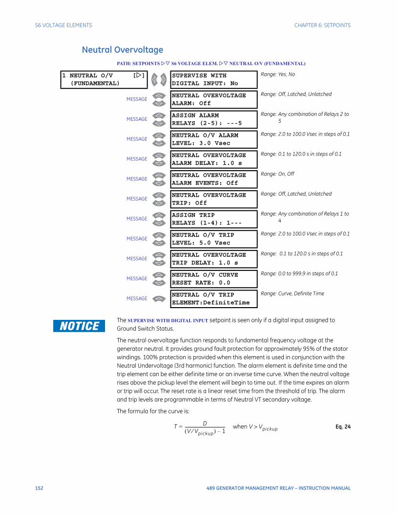
152 489 GENERATOR MANAGEMENT RELAY – INSTRUCTION MANUAL
S6 VOLTAGE ELEMENTS CHAPTER 6: SETPOINTS
Neutral OvervoltagePATH: SETPOINTS S6 VOLTAGE ELEM. NEUTRAL O/V (FUNDAMENTAL)
The SUPERVISE WITH DIGITAL INPUT setpoint is seen only if a digital input assigned to Ground Switch Status.
The neutral overvoltage function responds to fundamental frequency voltage at the generator neutral. It provides ground fault protection for approximately 95% of the stator windings. 100% protection is provided when this element is used in conjunction with the Neutral Undervoltage (3rd harmonic) function. The alarm element is definite time and the trip element can be either definite time or an inverse time curve. When the neutral voltage rises above the pickup level the element will begin to time out. If the time expires an alarm or trip will occur. The reset rate is a linear reset time from the threshold of trip. The alarm and trip levels are programmable in terms of Neutral VT secondary voltage.
The formula for the curve is:
Eq. 24
1 NEUTRAL O/V [](FUNDAMENTAL)
SUPERVISE WITHDIGITAL INPUT: No
Range: Yes, No
MESSAGENEUTRAL OVERVOLTAGEALARM: Off
Range: Off, Latched, Unlatched
MESSAGEASSIGN ALARMRELAYS (2-5): ---5
Range: Any combination of Relays 2 to 5
MESSAGENEUTRAL O/V ALARMLEVEL: 3.0 Vsec
Range: 2.0 to 100.0 Vsec in steps of 0.1
MESSAGENEUTRAL OVERVOLTAGEALARM DELAY: 1.0 s
Range: 0.1 to 120.0 s in steps of 0.1
MESSAGENEUTRAL OVERVOLTAGEALARM EVENTS: Off
Range: On, Off
MESSAGENEUTRAL OVERVOLTAGETRIP: Off
Range: Off, Latched, Unlatched
MESSAGEASSIGN TRIPRELAYS (1-4): 1---
Range: Any combination of Relays 1 to 4
MESSAGENEUTRAL O/V TRIPLEVEL: 5.0 Vsec
Range: 2.0 to 100.0 Vsec in steps of 0.1
MESSAGENEUTRAL OVERVOLTAGETRIP DELAY: 1.0 s
Range: 0.1 to 120.0 s in steps of 0.1
MESSAGENEUTRAL O/V CURVERESET RATE: 0.0
Range: 0.0 to 999.9 in steps of 0.1
MESSAGENEUTRAL O/V TRIPELEMENT:DefiniteTime
Range: Curve, Definite Time
T DV Vpickup⁄( ) 1–
---------------------------------------= when V Vpickup>
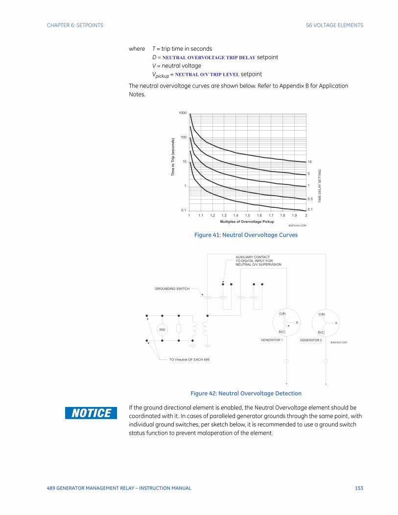
CHAPTER 6: SETPOINTS S6 VOLTAGE ELEMENTS
489 GENERATOR MANAGEMENT RELAY – INSTRUCTION MANUAL 153
where T = trip time in secondsD = NEUTRAL OVERVOLTAGE TRIP DELAY setpointV = neutral voltageVpickup = NEUTRAL O/V TRIP LEVEL setpoint
The neutral overvoltage curves are shown below. Refer to Appendix B for Application Notes.
Figure 41: Neutral Overvoltage Curves
Figure 42: Neutral Overvoltage Detection
If the ground directional element is enabled, the Neutral Overvoltage element should be coordinated with it . In cases of paralleled generator grounds through the same point, with individual ground switches, per sketch below, it is recommended to use a ground switch status function to prevent maloperation of the element.
808741A1.CDR
0.1
1
10
100
1000
1 1.1 1.2 1.3 1.4 1.5 1.6 1.7 1.8 1.9 2
Multiples of Overvoltage Pickup
10
3
1
0.3
0.1
Tim
eto
Trip
(se
co
nd
s)
TIM
ED
ELA
YS
ET
TIN
G
59G
A A
C(B) C(B)
B(C)
GENERATOR 1 GENERATOR 2
B(C)
TO Vneutral OF EACH 489
AUXILIARY CONTACT
TO DIGITAL INPUT FOR
NEUTRAL O/V SUPERVISION
GROUNDING SWITCH
808816A3.CDR
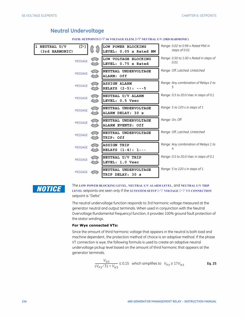
154 489 GENERATOR MANAGEMENT RELAY – INSTRUCTION MANUAL
S6 VOLTAGE ELEMENTS CHAPTER 6: SETPOINTS
Neutral UndervoltagePATH: SETPOINTS S6 VOLTAGE ELEM. NEUTRAL U/V (3RD HARMONIC)
The LOW POWER BLOCKING LEVEL, NEUTRAL U/V ALARM LEVEL, and NEUTRAL U/V TRIP
LEVEL setpoints are seen only if the S2 SYSTEM SETUP VOLTAGE VT CONNECTION setpoint is “Delta”
The neutral undervoltage function responds to 3rd harmonic voltage measured at the generator neutral and output terminals. When used in conjunction with the Neutral Overvoltage (fundamental frequency) function, it provides 100% ground fault protection of the stator windings.
For Wye connected VTs:
Since the amount of third harmonic voltage that appears in the neutral is both load and machine dependent, the protection method of choice is an adaptive method. If the phase VT connection is wye, the following formula is used to create an adaptive neutral undervoltage pickup level based on the amount of third harmonic that appears at the generator terminals.
Eq. 25
1 NEUTRAL U/V [](3rd HARMONIC)
LOW POWER BLOCKINGLEVEL: 0.05 x Rated MW
Range: 0.02 to 0.99 × Rated MW in steps of 0.01
MESSAGELOW VOLTAGE BLOCKINGLEVEL: 0.75 x Rated
Range: 0.50 to 1.00 × Rated in steps of 0.01
MESSAGENEUTRAL UNDERVOLTAGEALARM: Off
Range: Off, Latched, Unlatched
MESSAGEASSIGN ALARMRELAYS (2-5): ---5
Range: Any combination of Relays 2 to 5
MESSAGENEUTRAL U/V ALARMLEVEL: 0.5 Vsec
Range: 0.5 to 20.0 Vsec in steps of 0.1
MESSAGENEUTRAL UNDERVOLTAGEALARM DELAY: 30 s
Range: 5 to 120 s in steps of 1
MESSAGENEUTRAL UNDERVOLTAGEALARM EVENTS: Off
Range: On, Off
MESSAGENEUTRAL UNDERVOLTAGETRIP: Off
Range: Off, Latched, Unlatched
MESSAGEASSIGN TRIPRELAYS (1-4): 1---
Range: Any combination of Relays 1 to 4
MESSAGENEUTRAL U/V TRIPLEVEL: 1.0 Vsec
Range: 0.5 to 20.0 Vsec in steps of 0.1
MESSAGENEUTRAL UNDERVOLTAGETRIP DELAY: 30 s
Range: 5 to 120 s in steps of 1
VN3
VP3 3⁄( ) VN3+------------------------------------ 0.15 which simplifies to VP3 17VN3≥≤

CHAPTER 6: SETPOINTS S6 VOLTAGE ELEMENTS
489 GENERATOR MANAGEMENT RELAY – INSTRUCTION MANUAL 155
The 489 tests the following permissives prior to testing the basic operating equation to ensure that VN3’ should be of a measurable magnitude for an unfaulted generator:
Eq. 26
where: VN3 = magnitude of the third harmonic voltage at generator neutral;VP3 = magnitude of the third harmonic voltage at the generator terminalsVP3´ = VT secondary magnitude of the third harmonic voltage measured at the generator terminals;VN3´ = VT sec. magnitude of 3rd harmonic voltage at generator neutral;Threshold = 0.15 V for the alarm element and 0.1875 V for the trip element
For Open Delta connected VTs:
If the phase VT connection is open delta, it is not possible to measure the third harmonic voltages at the generator terminals and a simple third harmonic neutral undervoltage element is used. The level is programmable in terms of Neutral VT secondary voltage. In order to prevent nuisance tripping at low load or low generator voltages, two blocking functions are provided. They apply to both the alarm and trip functions. When used as a simple undervoltage element, settings should be based on measured 3rd harmonic neutral voltage of the healthy machine.
This method of using 3rd harmonic voltages to detect stator ground faults near the generator neutral has proved feasible on generators with unit transformers. Its usefulness in other generator applications is unknown.
VP3′ 0.25 V and VP3′ Threshold 17 Neutral VT RatioPhase VT Ratio
----------------------------------------××≥>

156 489 GENERATOR MANAGEMENT RELAY – INSTRUCTION MANUAL
S6 VOLTAGE ELEMENTS CHAPTER 6: SETPOINTS
Loss of ExcitationPATH: SETPOINTS S6 VOLTAGE ELEM. LOSS OF EXCITATION
The VOLTAGE LEVEL setpoint is seen only if ENABLE VOLTAGE SUPERVISION is set to “Yes”.
Loss of excitation is detected with an impedance element. When the impedance falls within the impedance circle for the specified delay time, a trip will occur if it is enabled. Circles 1 and/or 2 can be tuned to a particular system. The larger circle diameter should be set to the synchronous reactance of the generator, xd, and the circle offset to the generator transient reactance x’d / 2. Typically the smaller circle (if used) is set to minimum time with a diameter set to 0.7xd and an offset of x’d / 2. This feature is blocked if voltage supervision is enabled and the generator voltage is above the VOLTAGE LEVEL setpoint. The trip feature is supervised by minimum current of 0.05 × CT. Note that the Loss of Excitation element will be blocked if there is a VT fuse failure or if the generator is offline. Also, it uses output CT inputs.
The secondary phase-phase loss of excitation impedance is defined as:
Eq. 27
where: Zloe = secondary phase-to-phase loss of excitation impedanceMloe∠θloe= Secondary impedance phasor (magnitude and angle)
1 LOSS OF []EXCITATION
ENABLE VOLTAGESUPERVISION: Yes
Range: Yes, No
MESSAGEVOLTAGELEVEL: 0.70 x Rated
Range: 0.70 to 1.00 × Rated in steps of 0.01
MESSAGECIRCLE 1TRIP: Off
Range: Off, Latched, Unlatched
MESSAGEASSIGN CIRCLE 1 TRIPRELAYS (1-4): 1---
Range: Any combination of Relays 1 to 4
MESSAGECIRCLE 1DIAMETER: 25.0 Ωsec
Range: 2.5 to 300.0 Ωsec in steps of 0.1
MESSAGECIRCLE 1OFFSET: 2.5 Ωsec
Range: 1.0 to 300.0 Ωsec in steps of 0.1
MESSAGECIRCLE 1 TRIPDELAY: 5.0 s
Range: 0.1 to 10.0 s in steps of 0.1
MESSAGECIRCLE 2TRIP: Off
Range: Off, Latched, Unlatched
MESSAGEASSIGN CIRCLE 2 TRIPRELAYS (1-4): 1---
Range: Any combination of Relays 1 to 4
MESSAGECIRCLE 2DIAMETER: 35.0 Ωsec
Range: 2.5 to 300.0 Ωsec in steps of 0.1
MESSAGECIRCLE 2OFFSET: 2.5 Ωsec
Range: 1.0 to 300.0 Ωsec in steps of 0.1
MESSAGECIRCLE 2 TRIPDELAY: 5.0 s
Range: 0.1 to 10.0 s in steps of 0.1
ZloeVAB
IA IB–-------------- Mloe θloe∠= =
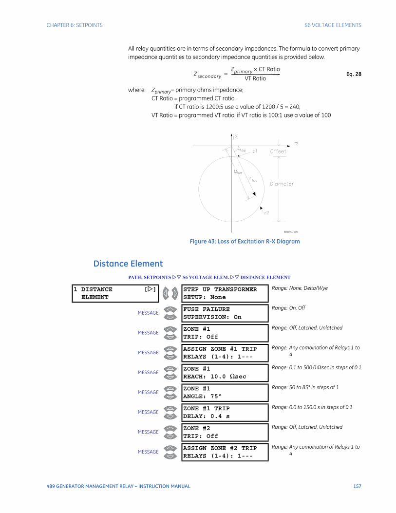
CHAPTER 6: SETPOINTS S6 VOLTAGE ELEMENTS
489 GENERATOR MANAGEMENT RELAY – INSTRUCTION MANUAL 157
All relay quantities are in terms of secondary impedances. The formula to convert primary impedance quantities to secondary impedance quantities is provided below.
Eq. 28
where: Zprimary= primary ohms impedance;CT Ratio = programmed CT ratio,
if CT ratio is 1200:5 use a value of 1200 / 5 = 240;VT Ratio = programmed VT ratio, if VT ratio is 100:1 use a value of 100
Figure 43: Loss of Excitation R-X Diagram
Distance ElementPATH: SETPOINTS S6 VOLTAGE ELEM. DISTANCE ELEMENT
Z ondarysecZprimary CT Ratio×
VT Ratio------------------------------------------------=
1 DISTANCE []ELEMENT
STEP UP TRANSFORMERSETUP: None
Range: None, Delta/Wye
MESSAGEFUSE FAILURESUPERVISION: On
Range: On, Off
MESSAGEZONE #1TRIP: Off
Range: Off, Latched, Unlatched
MESSAGEASSIGN ZONE #1 TRIPRELAYS (1-4): 1---
Range: Any combination of Relays 1 to 4
MESSAGEZONE #1REACH: 10.0 Ωsec
Range: 0.1 to 500.0 Ωsec in steps of 0.1
MESSAGEZONE #1ANGLE: 75°
Range: 50 to 85° in steps of 1
MESSAGEZONE #1 TRIPDELAY: 0.4 s
Range: 0.0 to 150.0 s in steps of 0.1
MESSAGEZONE #2TRIP: Off
Range: Off, Latched, Unlatched
MESSAGEASSIGN ZONE #2 TRIPRELAYS (1-4): 1---
Range: Any combination of Relays 1 to 4
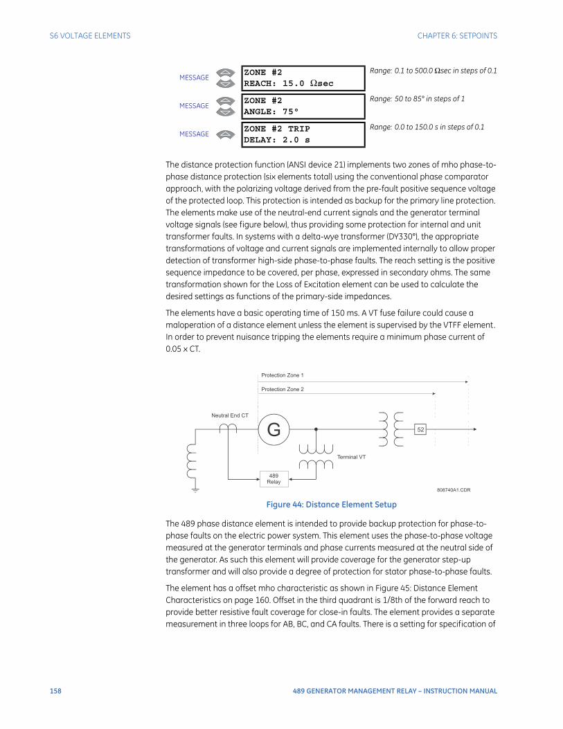
158 489 GENERATOR MANAGEMENT RELAY – INSTRUCTION MANUAL
S6 VOLTAGE ELEMENTS CHAPTER 6: SETPOINTS
The distance protection function (ANSI device 21) implements two zones of mho phase-to-phase distance protection (six elements total) using the conventional phase comparator approach, with the polarizing voltage derived from the pre-fault positive sequence voltage of the protected loop. This protection is intended as backup for the primary line protection. The elements make use of the neutral-end current signals and the generator terminal voltage signals (see figure below), thus providing some protection for internal and unit transformer faults. In systems with a delta-wye transformer (DY330°), the appropriate transformations of voltage and current signals are implemented internally to allow proper detection of transformer high-side phase-to-phase faults. The reach setting is the positive sequence impedance to be covered, per phase, expressed in secondary ohms. The same transformation shown for the Loss of Excitation element can be used to calculate the desired settings as functions of the primary-side impedances.
The elements have a basic operating time of 150 ms. A VT fuse failure could cause a maloperation of a distance element unless the element is supervised by the VTFF element. In order to prevent nuisance tripping the elements require a minimum phase current of 0.05 x CT.
Figure 44: Distance Element Setup
The 489 phase distance element is intended to provide backup protection for phase-to-phase faults on the electric power system. This element uses the phase-to-phase voltage measured at the generator terminals and phase currents measured at the neutral side of the generator. As such this element will provide coverage for the generator step-up transformer and will also provide a degree of protection for stator phase-to-phase faults.
The element has a offset mho characteristic as shown in Figure 45: Distance Element Characteristics on page 160. Offset in the third quadrant is 1/8th of the forward reach to provide better resistive fault coverage for close-in faults. The element provides a separate measurement in three loops for AB, BC, and CA faults. There is a setting for specification of
MESSAGEZONE #2REACH: 15.0 Ωsec
Range: 0.1 to 500.0 Ωsec in steps of 0.1
MESSAGEZONE #2ANGLE: 75°
Range: 50 to 85° in steps of 1
MESSAGEZONE #2 TRIPDELAY: 2.0 s
Range: 0.0 to 150.0 s in steps of 0.1
808740A1.CDR
Protection Zone 1
Protection Zone 2
Neutral End CT
52
Terminal VT
489
Relay

CHAPTER 6: SETPOINTS S6 VOLTAGE ELEMENTS
489 GENERATOR MANAGEMENT RELAY – INSTRUCTION MANUAL 159
the step-up transformer connection. If this setting is chosen as “None”, then it is assumed that the transformer is Wye-Wye connected or that there is no step-up transformer. In this case the element will use the following operating quantities.
If this setting is chosen as “Delta/Wye” then it is assumed that the transformer is Yd1 or Yd11. In this case the following operating quantities are used.
The first zone is typically used to provide a backup protection for a step-up transformer and generator system bus protection (generator impedance should not be included into reach setting). The reach is set to cover the step-up transformer impedance with some margin, say 25%. The time delay should be coordinated with step up transformer and bus backup protection.
The second zone reach is typically set to cover the longest transmission line or feeder leaving the generating station. Care must be taken for possible under-reaching effects due to the fault contribution from other lines or generators. The element is intended for backup protection and therefore time delay should always be included. This element is typically set to coordinate with the longest operating time of the system distance relays protecting lines leaving station.
The measuring point of the element is defined by the location of the VT and CT as shown in Figure 44: Distance Element Setup on page 158. Therefore, the impedance of the step-up transformer should be included and the impedance of the generator should not be included. Care should also be taken to ensure the apparent impedance seen by the element when the machine is operating at worst-case load and power factor does not encroach into the operating characteristic. The reach setting is in secondary ohms. The minimum operating time of the element is 150 ms to coordinate with VTFF operating time (99 ms).
Element Voltage Current
AB Va – Vb Ia – Ib
BC Vb – Vc Ib – Ic
CA Vc – Va Ic – Ia
Element Voltage Current
AB (Vab – Vca) / × Ia
BC (Vbc – Vab) / × Ib
CA (Vca – Vbc) / × Ic
3 3
3 3
3 3
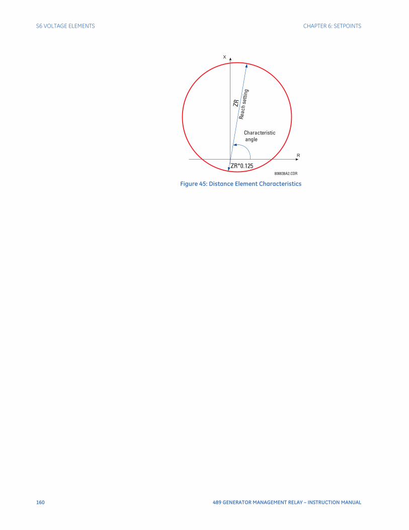
160 489 GENERATOR MANAGEMENT RELAY – INSTRUCTION MANUAL
S6 VOLTAGE ELEMENTS CHAPTER 6: SETPOINTS
Figure 45: Distance Element Characteristics
808838A2.CDR
Characteristicangle
Reac
hse
tting
ZR
ZR*0.125

CHAPTER 6: SETPOINTS S7 POWER ELEMENTS
489 GENERATOR MANAGEMENT RELAY – INSTRUCTION MANUAL 161
S7 Power Elements
Power Measurement ConventionsGeneration of power will be displayed on the 489 as positive watts. By convention, an induction generator normally requires reactive power from the system for excitation. This is displayed on the 489 as negative vars. A synchronous generator on the other hand has its own source of excitation and can be operated with either lagging or leading power factor. This is displayed on the 489 as positive vars and negative vars, respectively. All power quantities are measured from the phase-phase voltage and the currents measured at the output CTs.
Figure 46: Power Measurement Conventions
I1
I2
I3
I4
^
^
^
^
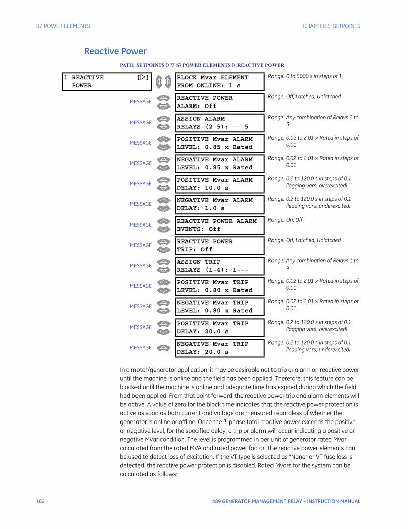
162 489 GENERATOR MANAGEMENT RELAY – INSTRUCTION MANUAL
S7 POWER ELEMENTS CHAPTER 6: SETPOINTS
Reactive PowerPATH: SETPOINTS S7 POWER ELEMENTS REACTIVE POWER
In a motor/generator application, it may be desirable not to trip or alarm on reactive power until the machine is online and the field has been applied. Therefore, this feature can be blocked until the machine is online and adequate time has expired during which the field had been applied. From that point forward, the reactive power trip and alarm elements will be active. A value of zero for the block time indicates that the reactive power protection is active as soon as both current and voltage are measured regardless of whether the generator is online or offline. Once the 3-phase total reactive power exceeds the positive or negative level, for the specified delay, a trip or alarm will occur indicating a positive or negative Mvar condition. The level is programmed in per unit of generator rated Mvar calculated from the rated MVA and rated power factor. The reactive power elements can be used to detect loss of excitation. If the VT type is selected as “None” or VT fuse loss is detected, the reactive power protection is disabled. Rated Mvars for the system can be calculated as follows:
1 REACTIVE []POWER
BLOCK Mvar ELEMENTFROM ONLINE: 1 s
Range: 0 to 5000 s in steps of 1
MESSAGEREACTIVE POWERALARM: Off
Range: Off, Latched, Unlatched
MESSAGEASSIGN ALARMRELAYS (2-5): ---5
Range: Any combination of Relays 2 to 5
MESSAGEPOSITIVE Mvar ALARMLEVEL: 0.85 x Rated
Range: 0.02 to 2.01 × Rated in steps of 0.01
MESSAGENEGATIVE Mvar ALARMLEVEL: 0.85 x Rated
Range: 0.02 to 2.01 × Rated in steps of 0.01
MESSAGEPOSITIVE Mvar ALARMDELAY: 10.0 s
Range: 0.2 to 120.0 s in steps of 0.1 (lagging vars, overexcited)
MESSAGENEGATIVE Mvar ALARMDELAY: 1.0 s
Range: 0.2 to 120.0 s in steps of 0.1 (leading vars, underexcited)
MESSAGEREACTIVE POWER ALARMEVENTS: Off
Range: On, Off
MESSAGEREACTIVE POWERTRIP: Off
Range: Off, Latched, Unlatched
MESSAGEASSIGN TRIPRELAYS (1-4): 1---
Range: Any combination of Relays 1 to 4
MESSAGEPOSITIVE Mvar TRIPLEVEL: 0.80 x Rated
Range: 0.02 to 2.01 × Rated in steps of 0.01
MESSAGENEGATIVE Mvar TRIPLEVEL: 0.80 x Rated
Range: 0.02 to 2.01 × Rated in steps of 0.01
MESSAGEPOSITIVE Mvar TRIPDELAY: 20.0 s
Range: 0.2 to 120.0 s in steps of 0.1 (lagging vars, overexcited)
MESSAGENEGATIVE Mvar TRIPDELAY: 20.0 s
Range: 0.2 to 120.0 s in steps of 0.1 (leading vars, underexcited)
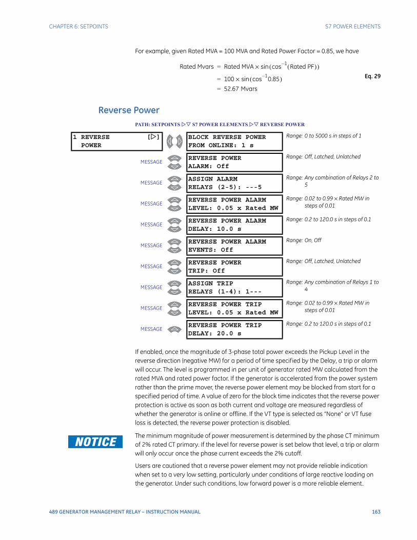
CHAPTER 6: SETPOINTS S7 POWER ELEMENTS
489 GENERATOR MANAGEMENT RELAY – INSTRUCTION MANUAL 163
For example, given Rated MVA = 100 MVA and Rated Power Factor = 0.85, we have
Eq. 29
Reverse PowerPATH: SETPOINTS S7 POWER ELEMENTS REVERSE POWER
If enabled, once the magnitude of 3-phase total power exceeds the Pickup Level in the reverse direction (negative MW) for a period of time specified by the Delay, a trip or alarm will occur. The level is programmed in per unit of generator rated MW calculated from the rated MVA and rated power factor. If the generator is accelerated from the power system rather than the prime mover, the reverse power element may be blocked from start for a specified period of time. A value of zero for the block time indicates that the reverse power protection is active as soon as both current and voltage are measured regardless of whether the generator is online or offline. If the VT type is selected as “None” or VT fuse loss is detected, the reverse power protection is disabled.
The minimum magnitude of power measurement is determined by the phase CT minimum of 2% rated CT primary. If the level for reverse power is set below that level, a trip or alarm will only occur once the phase current exceeds the 2% cutoff.
Users are cautioned that a reverse power element may not provide reliable indication when set to a very low setting, particularly under conditions of large reactive loading on the generator. Under such conditions, low forward power is a more reliable element.
Rated Mvars Rated MVA cos 1– Rated PF( )( )sin×=
100 cos 1– 0.85( )sin×=
52.67 Mvars=
1 REVERSE []POWER
BLOCK REVERSE POWERFROM ONLINE: 1 s
Range: 0 to 5000 s in steps of 1
MESSAGEREVERSE POWERALARM: Off
Range: Off, Latched, Unlatched
MESSAGEASSIGN ALARMRELAYS (2-5): ---5
Range: Any combination of Relays 2 to 5
MESSAGEREVERSE POWER ALARMLEVEL: 0.05 x Rated MW
Range: 0.02 to 0.99 × Rated MW in steps of 0.01
MESSAGEREVERSE POWER ALARMDELAY: 10.0 s
Range: 0.2 to 120.0 s in steps of 0.1
MESSAGEREVERSE POWER ALARMEVENTS: Off
Range: On, Off
MESSAGEREVERSE POWERTRIP: Off
Range: Off, Latched, Unlatched
MESSAGEASSIGN TRIPRELAYS (1-4): 1---
Range: Any combination of Relays 1 to 4
MESSAGEREVERSE POWER TRIPLEVEL: 0.05 x Rated MW
Range: 0.02 to 0.99 × Rated MW in steps of 0.01
MESSAGEREVERSE POWER TRIPDELAY: 20.0 s
Range: 0.2 to 120.0 s in steps of 0.1

164 489 GENERATOR MANAGEMENT RELAY – INSTRUCTION MANUAL
S7 POWER ELEMENTS CHAPTER 6: SETPOINTS
Low Forward PowerPATH: SETPOINTS S7 POWER ELEMENTS LOW FORWARD POWER
If enabled, once the magnitude of 3-phase total power in the forward direction (+MW) falls below the Pickup Level for a period of time specified by the Delay, an alarm will occur. The level is programmed in per unit of generator rated MW calculated from the rated MVA and rated power factor. The low forward power element is active only when the generator is online and will be blocked until the generator is brought online, for a period of time defined by the setpoint Block Low Fwd Power From Online. The pickup level should be set lower than expected generator loading during normal operations. If the VT type is selected as “None” or VT fuse loss is detected, the low forward power protection is disabled.
1 LOW FORWARD []POWER
BLOCK LOW FWD POWERFROM ONLINE: 0 s
Range: 0 to 15000 s in steps of 1
MESSAGELOW FORWARD POWERALARM: Off
Range: Off, Latched, Unlatched
MESSAGEASSIGN ALARMRELAYS (2-5): ---5
Range: Any combination of Relays 2 to 5
MESSAGELOW FWD POWER ALARMLEVEL: 0.05 x Rated MW
Range: 0.02 to 0.99 × Rated MW in steps of 0.01
MESSAGELOW FWD POWER ALARMDELAY: 10.0 s
Range: 0.2 to 120.0 s in steps of 0.1
MESSAGELOW FWD POWER ALARMEVENTS: Off
Range: On, Off
MESSAGELOW FORWARD POWERTRIP: Off
Range: Off, Latched, Unlatched
MESSAGEASSIGN TRIPRELAYS (1-4): 1---
Range: Any combination of Relays 1 to 4
MESSAGELOW FWD POWER TRIPLEVEL: 0.05 x Rated MW
Range: 0.02 to 0.99 × Rated MW in steps of 0.01
MESSAGELOW FWD POWER TRIPDELAY: 20.0 s
Range: 0.2 to 120.0 s in steps of 0.1

CHAPTER 6: SETPOINTS S8 RTD TEMPERATURE
489 GENERATOR MANAGEMENT RELAY – INSTRUCTION MANUAL 165
S8 RTD Temperature
RTD TypesPATH: SETPOINTS S8 RTD TEMPERATURE RTD TYPES
Each of the twelve RTDs may be configured as None or any one of four application types, Stator, Bearing, Ambient, or Other. Each of those types may in turn be any one of four different RTD types: 100 ohm Platinum, 120 ohm Nickel, 100 ohm Nickel, 10 ohm Copper. The table below lists RTD resistance vs. temperature.
1 RTD TYPES [] STATOR RTD TYPE:100 Ohm Platinum
Range: 100 Ohm Platinum, 120 Ohm Nickel, 100 Ohm Nickel, 10 Ohm Copper
MESSAGEBEARING RTD TYPE:100 Ohm Platinum
Range: as above
MESSAGEAMBIENT RTD TYPE:100 Ohm Platinum
Range: as above
MESSAGEOTHER RTD TYPE:100 Ohm Platinum
Range: as above
Table 11: RTD Temperature vs. Resistance
Temperature 100 Ω Pt(DIN 43760)
120 Ω Ni 100 Ω Ni 10 Ω Cu
° C ° F
–50 –58 80.31 86.17 71.81 7.10
–40 –40 84.27 92.76 77.30 7.49
–30 –22 88.22 99.41 82.84 7.88
–20 –4 92.16 106.15 88.45 8.26
–10 14 96.09 113.00 94.17 8.65
0 32 100.00 120.00 100.00 9.04
10 50 103.90 127.17 105.97 9.42
20 68 107.79 134.52 112.10 9.81
30 86 111.67 142.06 118.38 10.19
40 104 115.54 149.79 124.82 10.58
50 122 119.39 157.74 131.45 10.97
60 140 123.24 165.90 138.25 11.35
70 158 127.07 174.25 145.20 11.74
80 176 130.89 182.84 152.37 12.12
90 194 134.70 191.64 159.70 12.51
100 212 138.50 200.64 167.20 12.90
110 230 142.29 209.85 174.87 13.28
120 248 146.06 219.29 182.75 13.67
130 266 149.82 228.96 190.80 14.06
140 284 153.58 238.85 199.04 14.44
150 302 157.32 248.95 207.45 14.83
160 320 161.04 259.30 216.08 15.22
170 338 164.76 269.91 224.92 15.61
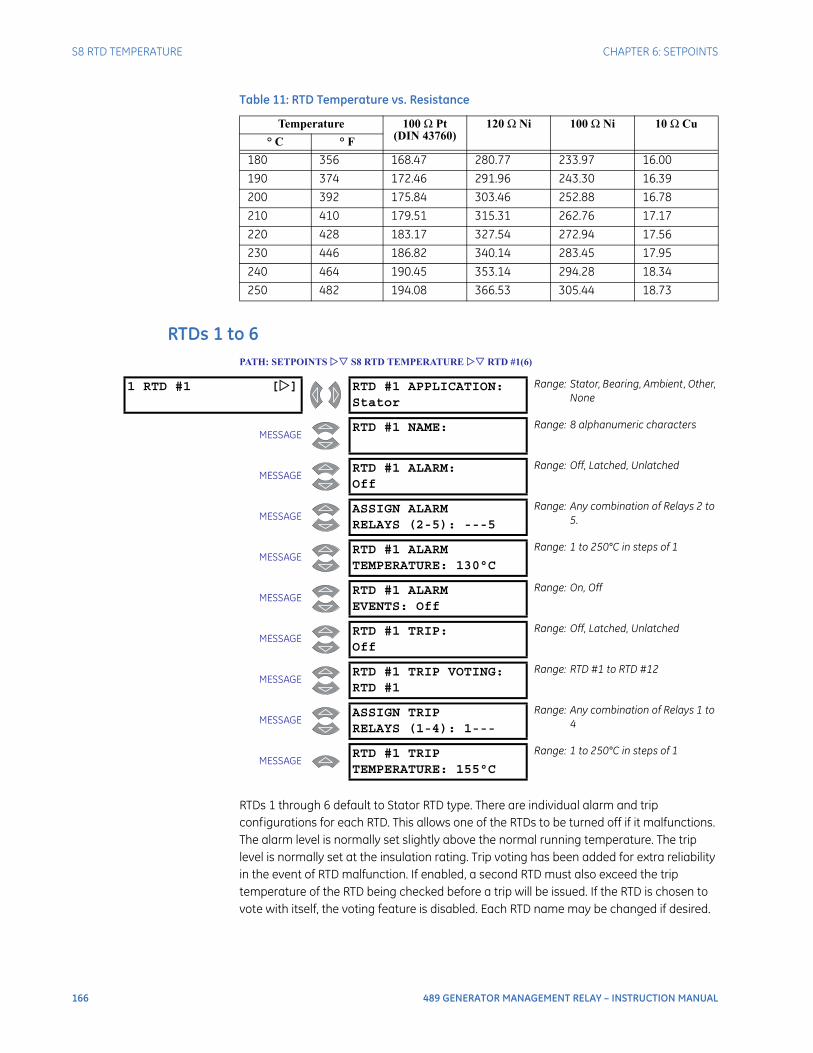
166 489 GENERATOR MANAGEMENT RELAY – INSTRUCTION MANUAL
S8 RTD TEMPERATURE CHAPTER 6: SETPOINTS
RTDs 1 to 6PATH: SETPOINTS S8 RTD TEMPERATURE RTD #1(6)
RTDs 1 through 6 default to Stator RTD type. There are individual alarm and trip configurations for each RTD. This allows one of the RTDs to be turned off if it malfunctions. The alarm level is normally set slightly above the normal running temperature. The trip level is normally set at the insulation rating. Trip voting has been added for extra reliability in the event of RTD malfunction. If enabled, a second RTD must also exceed the trip temperature of the RTD being checked before a trip will be issued. If the RTD is chosen to vote with itself, the voting feature is disabled. Each RTD name may be changed if desired.
180 356 168.47 280.77 233.97 16.00
190 374 172.46 291.96 243.30 16.39
200 392 175.84 303.46 252.88 16.78
210 410 179.51 315.31 262.76 17.17
220 428 183.17 327.54 272.94 17.56
230 446 186.82 340.14 283.45 17.95
240 464 190.45 353.14 294.28 18.34
250 482 194.08 366.53 305.44 18.73
Table 11: RTD Temperature vs. Resistance
Temperature 100 Ω Pt(DIN 43760)
120 Ω Ni 100 Ω Ni 10 Ω Cu
° C ° F
1 RTD #1 [] RTD #1 APPLICATION:Stator
Range: Stator, Bearing, Ambient, Other, None
MESSAGERTD #1 NAME: Range: 8 alphanumeric characters
MESSAGERTD #1 ALARM:Off
Range: Off, Latched, Unlatched
MESSAGEASSIGN ALARMRELAYS (2-5): ---5
Range: Any combination of Relays 2 to 5.
MESSAGERTD #1 ALARMTEMPERATURE: 130°C
Range: 1 to 250°C in steps of 1
MESSAGERTD #1 ALARMEVENTS: Off
Range: On, Off
MESSAGERTD #1 TRIP:Off
Range: Off, Latched, Unlatched
MESSAGERTD #1 TRIP VOTING:RTD #1
Range: RTD #1 to RTD #12
MESSAGEASSIGN TRIPRELAYS (1-4): 1---
Range: Any combination of Relays 1 to 4
MESSAGERTD #1 TRIPTEMPERATURE: 155°C
Range: 1 to 250°C in steps of 1
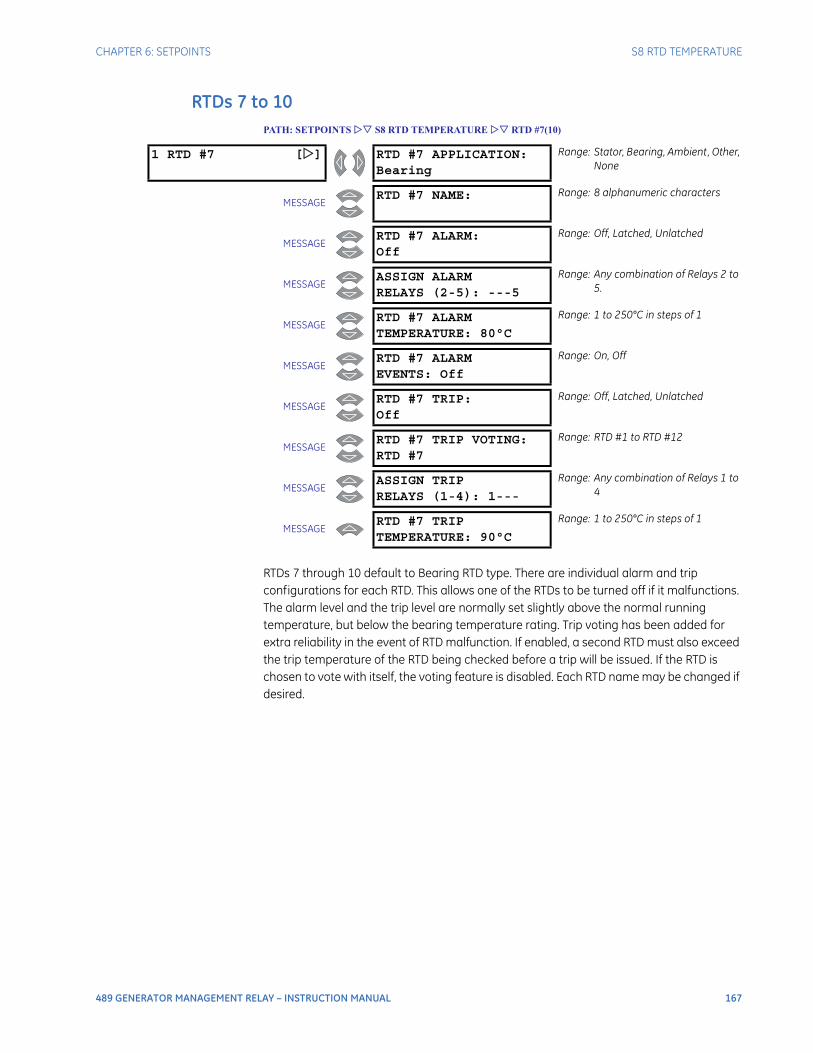
CHAPTER 6: SETPOINTS S8 RTD TEMPERATURE
489 GENERATOR MANAGEMENT RELAY – INSTRUCTION MANUAL 167
RTDs 7 to 10PATH: SETPOINTS S8 RTD TEMPERATURE RTD #7(10)
RTDs 7 through 10 default to Bearing RTD type. There are individual alarm and trip configurations for each RTD. This allows one of the RTDs to be turned off if it malfunctions. The alarm level and the trip level are normally set slightly above the normal running temperature, but below the bearing temperature rating. Trip voting has been added for extra reliability in the event of RTD malfunction. If enabled, a second RTD must also exceed the trip temperature of the RTD being checked before a trip will be issued. If the RTD is chosen to vote with itself, the voting feature is disabled. Each RTD name may be changed if desired.
1 RTD #7 [] RTD #7 APPLICATION:Bearing
Range: Stator, Bearing, Ambient, Other, None
MESSAGERTD #7 NAME: Range: 8 alphanumeric characters
MESSAGERTD #7 ALARM:Off
Range: Off, Latched, Unlatched
MESSAGEASSIGN ALARMRELAYS (2-5): ---5
Range: Any combination of Relays 2 to 5.
MESSAGERTD #7 ALARMTEMPERATURE: 80°C
Range: 1 to 250°C in steps of 1
MESSAGERTD #7 ALARMEVENTS: Off
Range: On, Off
MESSAGERTD #7 TRIP:Off
Range: Off, Latched, Unlatched
MESSAGERTD #7 TRIP VOTING:RTD #7
Range: RTD #1 to RTD #12
MESSAGEASSIGN TRIPRELAYS (1-4): 1---
Range: Any combination of Relays 1 to 4
MESSAGERTD #7 TRIPTEMPERATURE: 90°C
Range: 1 to 250°C in steps of 1
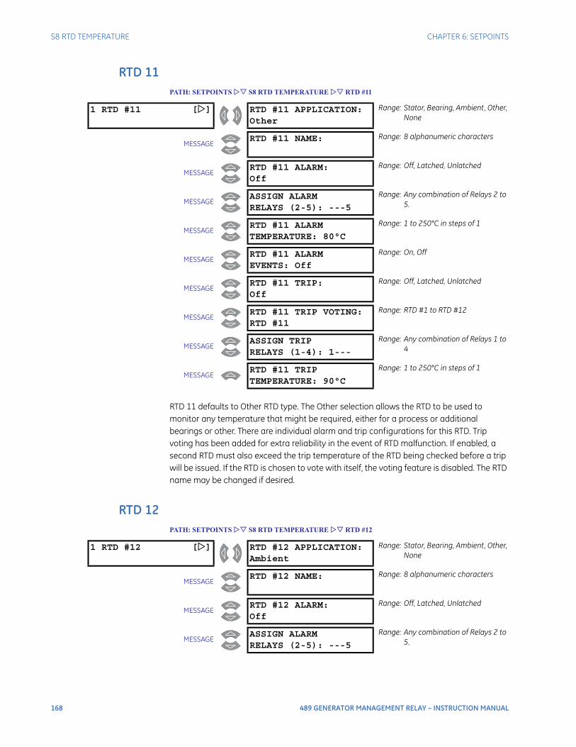
168 489 GENERATOR MANAGEMENT RELAY – INSTRUCTION MANUAL
S8 RTD TEMPERATURE CHAPTER 6: SETPOINTS
RTD 11PATH: SETPOINTS S8 RTD TEMPERATURE RTD #11
RTD 11 defaults to Other RTD type. The Other selection allows the RTD to be used to monitor any temperature that might be required, either for a process or additional bearings or other. There are individual alarm and trip configurations for this RTD. Trip voting has been added for extra reliability in the event of RTD malfunction. If enabled, a second RTD must also exceed the trip temperature of the RTD being checked before a trip will be issued. If the RTD is chosen to vote with itself, the voting feature is disabled. The RTD name may be changed if desired.
RTD 12PATH: SETPOINTS S8 RTD TEMPERATURE RTD #12
1 RTD #11 [] RTD #11 APPLICATION:Other
Range: Stator, Bearing, Ambient, Other, None
MESSAGERTD #11 NAME: Range: 8 alphanumeric characters
MESSAGERTD #11 ALARM:Off
Range: Off, Latched, Unlatched
MESSAGEASSIGN ALARMRELAYS (2-5): ---5
Range: Any combination of Relays 2 to 5.
MESSAGERTD #11 ALARMTEMPERATURE: 80°C
Range: 1 to 250°C in steps of 1
MESSAGERTD #11 ALARMEVENTS: Off
Range: On, Off
MESSAGERTD #11 TRIP:Off
Range: Off, Latched, Unlatched
MESSAGERTD #11 TRIP VOTING:RTD #11
Range: RTD #1 to RTD #12
MESSAGEASSIGN TRIPRELAYS (1-4): 1---
Range: Any combination of Relays 1 to 4
MESSAGERTD #11 TRIPTEMPERATURE: 90°C
Range: 1 to 250°C in steps of 1
1 RTD #12 [] RTD #12 APPLICATION:Ambient
Range: Stator, Bearing, Ambient, Other, None
MESSAGERTD #12 NAME: Range: 8 alphanumeric characters
MESSAGERTD #12 ALARM:Off
Range: Off, Latched, Unlatched
MESSAGEASSIGN ALARMRELAYS (2-5): ---5
Range: Any combination of Relays 2 to 5.

CHAPTER 6: SETPOINTS S8 RTD TEMPERATURE
489 GENERATOR MANAGEMENT RELAY – INSTRUCTION MANUAL 169
RTDs 12 defaults to Ambient RTD type. The Ambient selection allows the RTD to be used to monitor ambient temperature. There are individual alarm and trip configurations for this RTD. Trip voting has been added for extra reliability in the event of RTD malfunction. If enabled, a second RTD must also exceed the trip temperature of the RTD being checked before a trip will be issued. If the RTD is chosen to vote with itself, the voting feature is disabled. The RTD name may be changed if desired.
Open RTD SensorSETPOINTS S8 RTD TEMPERATURE OPEN RTD SENSOR
The 489 has an Open RTD Sensor Alarm. This alarm will look at all RTDs that have either an alarm or trip programmed and determine if an RTD connection has been broken. Any RTDs that do not have a trip or alarm associated with them will be ignored for this feature. When a broken sensor is detected, the assigned output relay will operate and a message will appear on the display identifying the RTD that is broken. It is recommended that if this feature is used, the alarm be programmed as latched so that intermittent RTDs are detected and corrective action may be taken.
MESSAGERTD #12 ALARMTEMPERATURE: 60°C
Range: 1 to 250°C in steps of 1
MESSAGERTD #12 ALARMEVENTS: Off
Range: On, Off
MESSAGERTD #12 TRIP:Off
Range: Off, Latched, Unlatched
MESSAGERTD #12 TRIP VOTING:RTD #12
Range: RTD #1 to RTD #12
MESSAGEASSIGN TRIPRELAYS (1-4): 1---
Range: Any combination of Relays 1 to 4
MESSAGERTD #12 TRIPTEMPERATURE: 80°C
Range: 1 to 250°C in steps of 1
1 OPEN RTD []SENSOR
OPEN RTD SENSOR:Off
Range: Off, Latched, Unlatched
MESSAGEASSIGN ALARMRELAYS (2-5): ---5
Range: Any combination of Relays 2 to 5
MESSAGEOPEN RTD SENSORALARM EVENTS: Off
Range: On, Off
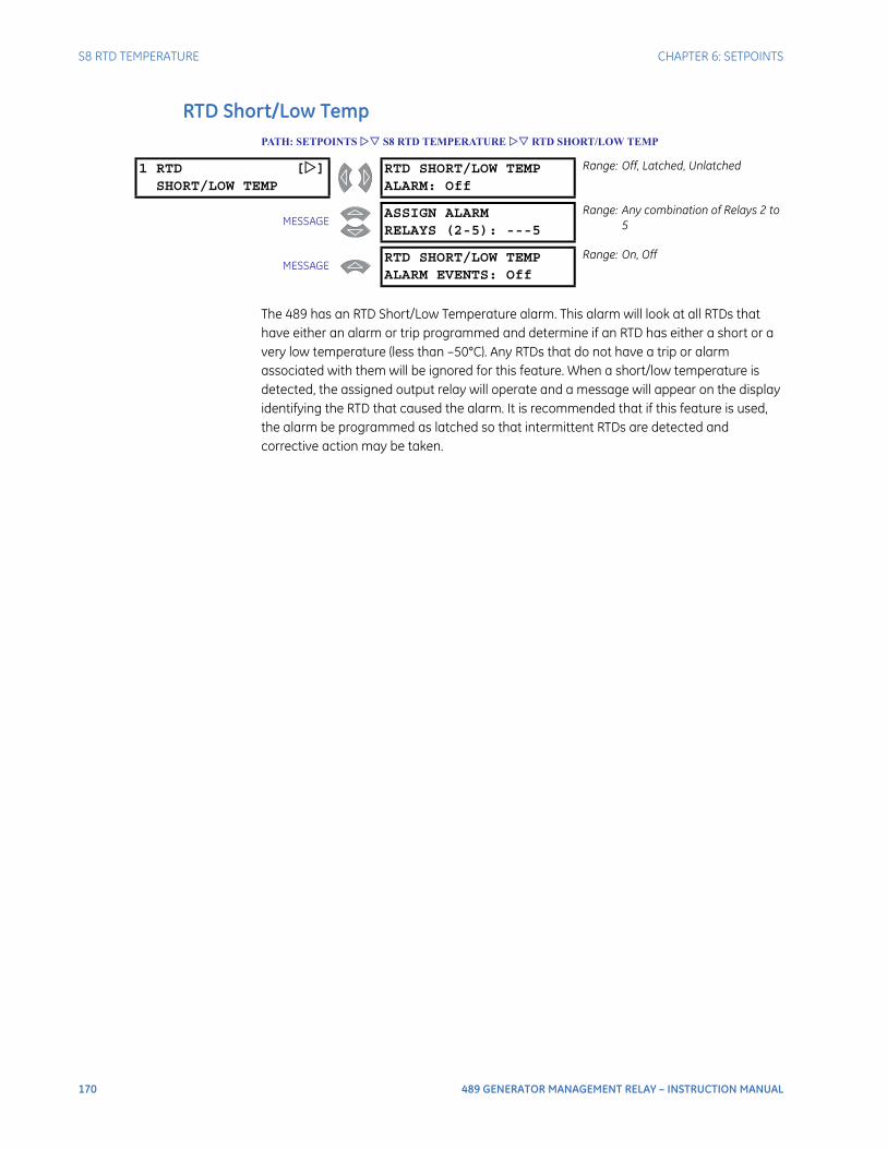
170 489 GENERATOR MANAGEMENT RELAY – INSTRUCTION MANUAL
S8 RTD TEMPERATURE CHAPTER 6: SETPOINTS
RTD Short/Low TempPATH: SETPOINTS S8 RTD TEMPERATURE RTD SHORT/LOW TEMP
The 489 has an RTD Short/Low Temperature alarm. This alarm will look at all RTDs that have either an alarm or trip programmed and determine if an RTD has either a short or a very low temperature (less than –50°C). Any RTDs that do not have a trip or alarm associated with them will be ignored for this feature. When a short/low temperature is detected, the assigned output relay will operate and a message will appear on the display identifying the RTD that caused the alarm. It is recommended that if this feature is used, the alarm be programmed as latched so that intermittent RTDs are detected and corrective action may be taken.
1 RTD []SHORT/LOW TEMP
RTD SHORT/LOW TEMPALARM: Off
Range: Off, Latched, Unlatched
MESSAGEASSIGN ALARMRELAYS (2-5): ---5
Range: Any combination of Relays 2 to 5
MESSAGERTD SHORT/LOW TEMPALARM EVENTS: Off
Range: On, Off

CHAPTER 6: SETPOINTS S9 THERMAL MODEL
489 GENERATOR MANAGEMENT RELAY – INSTRUCTION MANUAL 171
S9 Thermal Model
489 Thermal ModelThe thermal model of the 489 is primarily intended for induction generators, especially those that start on the system bus in the same manner as induction motors. However, some of the thermal model features may be used to model the heating that occurs in synchronous generators during overload conditions.
One of the principle enemies of generator life is heat. Generator thermal limits are dictated by the design of both the stator and the rotor. Induction generators that start on the system bus have three modes of operation: locked rotor or stall (when the rotor is not turning), acceleration (when the rotor is coming up to speed), and generating (when the rotor turns at super-synchronous speed). Heating occurs in the generator during each of these conditions in very distinct ways. Typically, during the generator starting, locked rotor and acceleration conditions, the generator will be rotor limited. That is to say that the rotor will approach its thermal limit before the stator. Under locked rotor conditions, voltage is induced in the rotor at line frequency, 50 or 60 Hz. This voltage causes a current to flow in the rotor, also at line frequency, and the heat generated (I2R) is a function of the effective rotor resistance. At 50 or 60 Hz, the reactance of the rotor cage causes the current to flow at the outer edges of the rotor bars. The effective resistance of the rotor is therefore at a maximum during a locked rotor condition as is rotor heating. When the generator is running at above rated speed, the voltage induced in the rotor is at a low frequency (approximately 1 Hz) and therefore, the effective resistance of the rotor is reduced quite dramatically. During overloads, the generator thermal limit is typically dictated by stator parameters. Some special generators might be all stator or all rotor limited. During acceleration, the dynamic nature of the generator slip dictates that rotor impedance is also dynamic, and a third thermal limit characteristic is necessary.
The figure below illustrates typical thermal limit curves for induction motors. The starting characteristic is shown for a high inertia load at 80% voltage. If the machine started quicker, the distinct characteristics of the thermal limit curves would not be required and the running overload curve would be joined with locked rotor safe stall times to produce a single overload curve.
The generator manufacturer should provide a safe stall time or thermal limit curves for any generator that is started as an induction motor. These thermal limits are intended to be used as guidelines and their definition is not always precise. When operation of the generator exceeds the thermal limit, the generator insulation does not immediately melt, rather, the rate of insulation degradation reaches a point where continued operation will significantly reduce generator life.
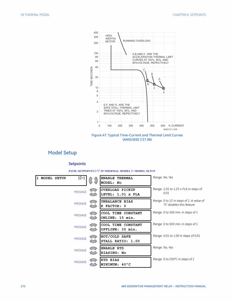
172 489 GENERATOR MANAGEMENT RELAY – INSTRUCTION MANUAL
S9 THERMAL MODEL CHAPTER 6: SETPOINTS
Figure 47: Typical Time-Current and Thermal Limit Curves(ANSI/IEEE C37.96)
Model Setup
Setpoints
PATH: SETPOINTS S9 THERMAL MODEL MODEL SETUP
1
10
8
6
4
2
100
80
60
40
20
200
300
400
0 100 200 300 400 500 600 % CURRENT
TIM
E-S
EC
ON
DS
HIGH
INERTIA
MOTOR RUNNING OVERLOAD
A
G
B
C
A,B,AND C ARE THE
ACCELERATION THERMAL LIMIT
CURVES AT 100%, 90%, AND
80%VOLTAGE, REPECTIVELY
E,F, AND G ARE THE
SAFE STALL THERMAL LIMIT
TIMES AT 100%, 90%, AND
80%VOLTAGE, REPECTIVELY
E
F
806827A1.CDR
1 MODEL SETUP [] ENABLE THERMALMODEL: No
Range: No, Yes
MESSAGEOVERLOAD PICKUPLEVEL: 1.01 x FLA
Range: 1.01 to 1.25 × FLA in steps of 0.01
MESSAGEUNBALANCE BIASK FACTOR: 0
Range: 0 to 12 in steps of 1. A value of “0” disables this feature
MESSAGECOOL TIME CONSTANTONLINE: 15 min.
Range: 0 to 500 min. in steps of 1
MESSAGECOOL TIME CONSTANTOFFLINE: 30 min.
Range: 0 to 500 min. in steps of 1
MESSAGEHOT/COLD SAFESTALL RATIO: 1.00
Range: 0.01 to 1.00 in steps of 0.01
MESSAGEENABLE RTDBIASING: No
Range: No, Yes
MESSAGERTD BIASMINIMUM: 40°C
Range: 0 to 250°C in steps of 1
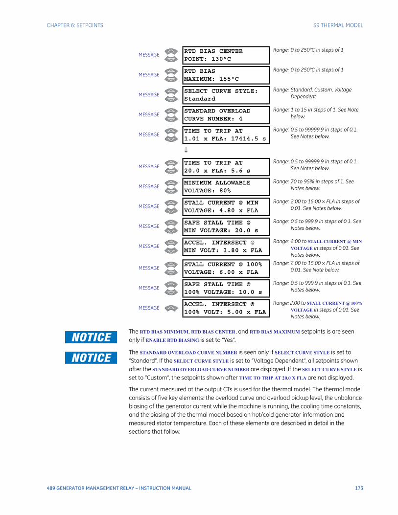
CHAPTER 6: SETPOINTS S9 THERMAL MODEL
489 GENERATOR MANAGEMENT RELAY – INSTRUCTION MANUAL 173
The RTD BIAS MINIMUM, RTD BIAS CENTER, and RTD BIAS MAXIMUM setpoints is are seen only if ENABLE RTD BIASING is set to “Yes”.
The STANDARD OVERLOAD CURVE NUMBER is seen only if SELECT CURVE STYLE is set to “Standard”. If the SELECT CURVE STYLE is set to “Voltage Dependent”, all setpoints shown after the STANDARD OVERLOAD CURVE NUMBER are displayed. If the SELECT CURVE STYLE is set to “Custom”, the setpoints shown after TIME TO TRIP AT 20.0 X FLA are not displayed.
The current measured at the output CTs is used for the thermal model. The thermal model consists of five key elements: the overload curve and overload pickup level, the unbalance biasing of the generator current while the machine is running, the cooling time constants, and the biasing of the thermal model based on hot/cold generator information and measured stator temperature. Each of these elements are described in detail in the sections that follow.
MESSAGERTD BIAS CENTERPOINT: 130°C
Range: 0 to 250°C in steps of 1
MESSAGERTD BIASMAXIMUM: 155°C
Range: 0 to 250°C in steps of 1
MESSAGESELECT CURVE STYLE:Standard
Range: Standard, Custom, Voltage Dependent
MESSAGESTANDARD OVERLOADCURVE NUMBER: 4
Range: 1 to 15 in steps of 1. See Note below.
MESSAGETIME TO TRIP AT1.01 x FLA: 17414.5 s
Range: 0.5 to 99999.9 in steps of 0.1. See Notes below.
↓
MESSAGETIME TO TRIP AT20.0 x FLA: 5.6 s
Range: 0.5 to 99999.9 in steps of 0.1. See Notes below.
MESSAGEMINIMUM ALLOWABLEVOLTAGE: 80%
Range: 70 to 95% in steps of 1. See Notes below.
MESSAGESTALL CURRENT @ MINVOLTAGE: 4.80 x FLA
Range: 2.00 to 15.00 × FLA in steps of 0.01. See Notes below.
MESSAGESAFE STALL TIME @MIN VOLTAGE: 20.0 s
Range: 0.5 to 999.9 in steps of 0.1. See Notes below.
MESSAGEACCEL. INTERSECT @MIN VOLT: 3.80 x FLA
Range: 2.00 to STALL CURRENT @ MIN
VOLTAGE in steps of 0.01. See Notes below.
MESSAGESTALL CURRENT @ 100%VOLTAGE: 6.00 x FLA
Range: 2.00 to 15.00 × FLA in steps of 0.01. See Note below.
MESSAGESAFE STALL TIME @100% VOLTAGE: 10.0 s
Range: 0.5 to 999.9 in steps of 0.1. See Notes below.
MESSAGEACCEL. INTERSECT @100% VOLT: 5.00 x FLA
Range: 2.00 to STALL CURRENT @ 100%
VOLTAGE in steps of 0.01. See Notes below.
174 489 GENERATOR MANAGEMENT RELAY – INSTRUCTION MANUAL
S9 THERMAL MODEL CHAPTER 6: SETPOINTS
The generator FLA is calculated as:
Eq. 30
The 489 integrates both stator and rotor heating into one model. Machine heating is reflected in a register called Thermal Capacity Used. If the machine has been stopped for a long period of time, it will be at ambient temperature and thermal capacity used should be zero. If the machine is in overload, once the thermal capacity used reaches 100%, a trip will occur.
The overload curve accounts for machine heating during stall, acceleration, and running in both the stator and the rotor. The Overload Pickup setpoint defines where the running overload curve begins as the generator enters an overload condition. This is useful to accommodate a service factor. The curve is effectively cut off at current values below this pickup.
Generator thermal limits consist of three distinct parts based on the three conditions of operation, locked rotor or stall, acceleration, and running overload. Each of these curves may be provided for both a hot and cold machine. A hot machine is defined as one that has been running for a period of time at full load such that the stator and rotor temperatures have settled at their rated temperature. A cold machine is defined as a machine that has been stopped for a period of time such that the stator and rotor temperatures have settled at ambient temperature. For most machines, the distinct characteristics of the thermal limits are formed into one smooth homogeneous curve. Sometimes only a safe stall time is provided. This is acceptable if the machine has been designed conservatively and can easily perform its required duty without infringing on the thermal limit. In this case, the protection can be conservative. If the machine has been designed very close to its thermal limits when operated as required, then the distinct characteristics of the thermal limits become important.
The 489 overload curve can take one of three formats, Standard, Custom Curve, or Voltage Dependent. Regardless of which curve style is selected, the 489 will retain thermal memory in the form of a register called Thermal Capacity Used. This register is updated every 50 ms using the following equation:
Eq. 31
where time to trip = time taken from the overload curve at Ieq as a function of FLA.
The overload protection curve should always be set slightly lower than the thermal limits provided by the manufacturer. This will ensure that the machine is tripped before the thermal limit is reached. If the starting times are well within the safe stall times, it is recommended that the 489 Standard Overload Curve be used. The standard overload curves are a series of 15 curves with a common curve shape based on typical generator thermal limit curves (see the following figure and table).
When the generator trips offline due to overload the generator will be locked out (the trip relay will stay latched) until generator thermal capacity reaches 15%.
Generator Rated MVA
3 Rated Generator Phase-Phase Voltage×--------------------------------------------------------------------------------------------------------------
TCused t TCused t 50ms–50 ms
time to trip--------------------------- 100%×+=
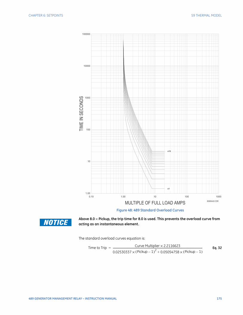
CHAPTER 6: SETPOINTS S9 THERMAL MODEL
489 GENERATOR MANAGEMENT RELAY – INSTRUCTION MANUAL 175
Figure 48: 489 Standard Overload Curves
Above 8.0 × Pickup, the trip time for 8.0 is used. This prevents the overload curve from acting as an instantaneous element.
The standard overload curves equation is:
Eq. 32
x1
x15
100000
10000
1000
100
10
1.00
0.10 1.00
MULTIPLE OF FULL LOAD AMPS
TIM
EIN
SE
CO
ND
S
10 100 1000
806804A5.CDR
Time to Trip Curve Multiplier 2.2116623×
0.02530337 Pickup 1–( )2× 0.05054758 Pickup 1–( )×+----------------------------------------------------------------------------------------------------------------------------------------------=

176 489 GENERATOR MANAGEMENT RELAY – INSTRUCTION MANUAL
S9 THERMAL MODEL CHAPTER 6: SETPOINTS
Table 12: 489 Standard Overload Curve Multipliers
PICKUP(× FLA)
STANDARD CURVE MULTIPLIERS
× 1 × 2 × 3 × 4 × 5 × 6 × 7 × 8 × 9 × 10 × 11 × 12 × 13 × 14 × 15
1.01
4353.6
8707.2
13061
17414
21768
26122
30475
34829
39183
43536
47890
52243
56597
60951
65304
1.05
853.71
1707.4
2561.1
3414.9
4268.6
5122.3
5976.0
6829.7
7683.4
8537.1
9390.8
10245
11098
11952
12806
1.10
416.68
833.36
1250.0
1666.7
2083.4
2500.1
2916.8
3333.5
3750.1
4166.8
4583.5
5000.2
5416.9
5833.6
6250.2
1.20
198.86
397.72
596.58
795.44
994.30
1193.2
1392.0
1590.9
1789.7
1988.6
2187.5
2386.3
2585.2
2784.1
2982.9
1.30
126.80
253.61
380.41
507.22
634.02
760.82
887.63
1014.4
1141.2
1268.0
1394.8
1521.6
1648.5
1775.3
1902.1
1.40
91.14
182.27
273.41
364.55
455.68
546.82
637.96
729.09
820.23
911.37
1002.5
1093.6
1184.8
1275.9
1367.0
1.50
69.99
139.98
209.97
279.96
349.95
419.94
489.93
559.92
629.91
699.90
769.89
839.88
909.87
979.86
1049.9
1.75
42.41
84.83
127.24
169.66
212.07
254.49
296.90
339.32
381.73
424.15
466.56
508.98
551.39
593.81
636.22
2.00
29.16
58.32
87.47
116.63
145.79
174.95
204.11
233.26
262.42
291.58
320.74
349.90
379.05
408.21
437.37
2.25
21.53
43.06
64.59
86.12
107.65
129.18
150.72
172.25
193.78
215.31
236.84
258.37
279.90
301.43
322.96
2.50
16.66
33.32
49.98
66.64
83.30
99.96
116.62
133.28
149.94
166.60
183.26
199.92
216.58
233.24
249.90
2.75
13.33
26.65
39.98
53.31
66.64
79.96
93.29
106.62
119.95
133.27
146.60
159.93
173.25
186.58
199.91
3.00
10.93
21.86
32.80
43.73
54.66
65.59
76.52
87.46
98.39
109.32
120.25
131.19
142.12
153.05
163.98
3.25
9.15 18.29
27.44
36.58
45.73
54.87
64.02
73.16
82.31
91.46
100.60
109.75
118.89
128.04
137.18
3.50
7.77 15.55
23.32
31.09
38.87
46.64
54.41
62.19
69.96
77.73
85.51
93.28
101.05
108.83
116.60
3.75
6.69 13.39
20.08
26.78
33.47
40.17
46.86
53.56
60.25
66.95
73.64
80.34
87.03
93.73
100.42
4.00
5.83 11.66
17.49
23.32
29.15
34.98
40.81
46.64
52.47
58.30
64.13
69.96
75.79
81.62
87.45
4.25
5.12 10.25
15.37
20.50
25.62
30.75
35.87
41.00
46.12
51.25
56.37
61.50
66.62
71.75
76.87
4.50
4.54 9.08 13.63
18.17
22.71
27.25
31.80
36.34
40.88
45.42
49.97
54.51
59.05
63.59
68.14
4.75
4.06 8.11 12.17
16.22
20.28
24.33
28.39
32.44
36.50
40.55
44.61
48.66
52.72
56.77
60.83
5.00
3.64 7.29 10.93
14.57
18.22
21.86
25.50
29.15
32.79
36.43
40.08
43.72
47.36
51.01
54.65
5.50
2.99 5.98 8.97 11.96
14.95
17.94
20.93
23.91
26.90
29.89
32.88
35.87
38.86
41.85
44.84
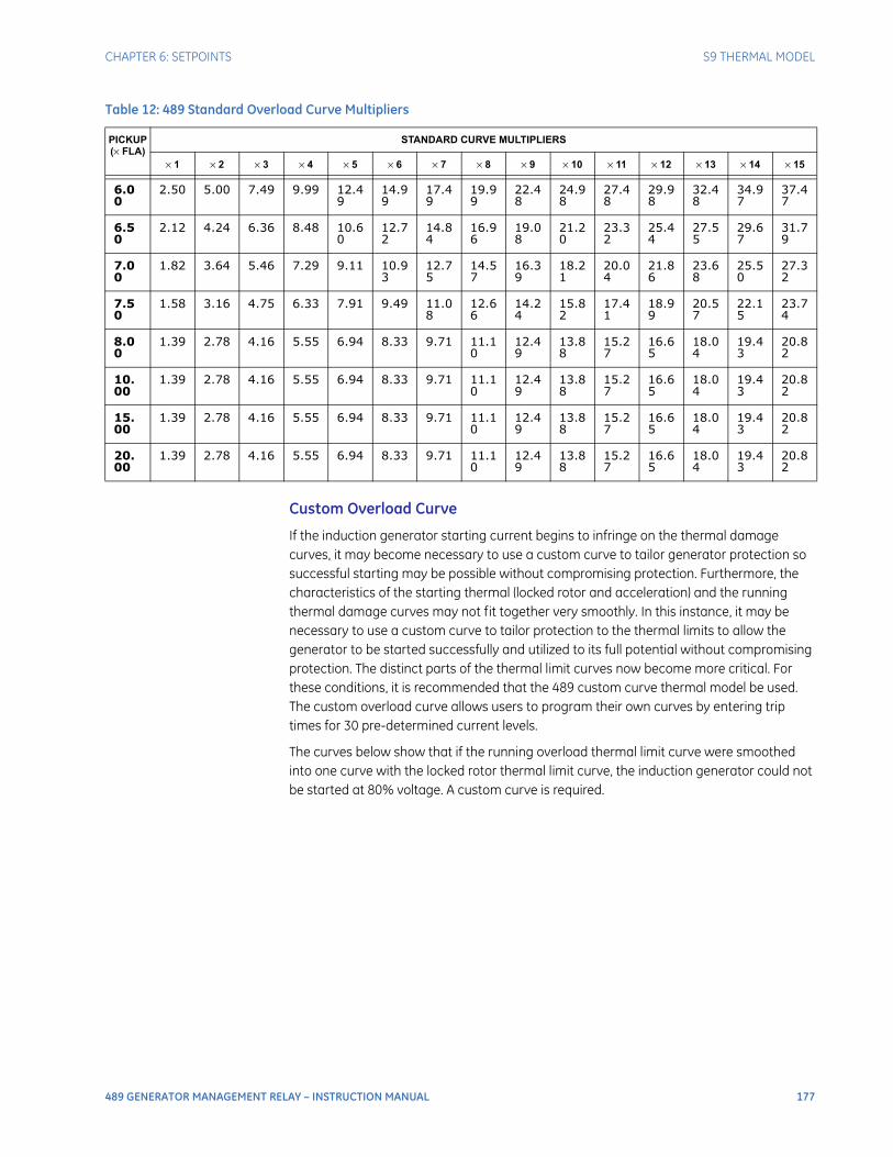
CHAPTER 6: SETPOINTS S9 THERMAL MODEL
489 GENERATOR MANAGEMENT RELAY – INSTRUCTION MANUAL 177
Custom Overload Curve
If the induction generator starting current begins to infringe on the thermal damage curves, it may become necessary to use a custom curve to tailor generator protection so successful starting may be possible without compromising protection. Furthermore, the characteristics of the starting thermal (locked rotor and acceleration) and the running thermal damage curves may not fit together very smoothly. In this instance, it may be necessary to use a custom curve to tailor protection to the thermal limits to allow the generator to be started successfully and utilized to its full potential without compromising protection. The distinct parts of the thermal limit curves now become more critical. For these conditions, it is recommended that the 489 custom curve thermal model be used. The custom overload curve allows users to program their own curves by entering trip times for 30 pre-determined current levels.
The curves below show that if the running overload thermal limit curve were smoothed into one curve with the locked rotor thermal limit curve, the induction generator could not be started at 80% voltage. A custom curve is required.
6.00
2.50 5.00 7.49 9.99 12.49
14.99
17.49
19.99
22.48
24.98
27.48
29.98
32.48
34.97
37.47
6.50
2.12 4.24 6.36 8.48 10.60
12.72
14.84
16.96
19.08
21.20
23.32
25.44
27.55
29.67
31.79
7.00
1.82 3.64 5.46 7.29 9.11 10.93
12.75
14.57
16.39
18.21
20.04
21.86
23.68
25.50
27.32
7.50
1.58 3.16 4.75 6.33 7.91 9.49 11.08
12.66
14.24
15.82
17.41
18.99
20.57
22.15
23.74
8.00
1.39 2.78 4.16 5.55 6.94 8.33 9.71 11.10
12.49
13.88
15.27
16.65
18.04
19.43
20.82
10.00
1.39 2.78 4.16 5.55 6.94 8.33 9.71 11.10
12.49
13.88
15.27
16.65
18.04
19.43
20.82
15.00
1.39 2.78 4.16 5.55 6.94 8.33 9.71 11.10
12.49
13.88
15.27
16.65
18.04
19.43
20.82
20.00
1.39 2.78 4.16 5.55 6.94 8.33 9.71 11.10
12.49
13.88
15.27
16.65
18.04
19.43
20.82
Table 12: 489 Standard Overload Curve Multipliers
PICKUP(× FLA)
STANDARD CURVE MULTIPLIERS
× 1 × 2 × 3 × 4 × 5 × 6 × 7 × 8 × 9 × 10 × 11 × 12 × 13 × 14 × 15
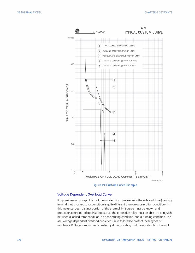
178 489 GENERATOR MANAGEMENT RELAY – INSTRUCTION MANUAL
S9 THERMAL MODEL CHAPTER 6: SETPOINTS
Figure 49: Custom Curve Example
Voltage Dependent Overload Curve
It is possible and acceptable that the acceleration time exceeds the safe stall time (bearing in mind that a locked rotor condition is quite different than an acceleration condition). In this instance, each distinct portion of the thermal limit curve must be known and protection coordinated against that curve. The protection relay must be able to distinguish between a locked rotor condition, an accelerating condition, and a running condition. The 489 voltage dependent overload curve feature is tailored to protect these types of machines. Voltage is monitored constantly during starting and the acceleration thermal
MULTIPLE OF FULL LOAD CURRENT SETPOINT
TIM
ET
OT
RIP
INS
EC
ON
DS
0.1
1.0
10
100
1000
10000
0.5
1
10
100
1000
1
2
3
4
5
2
3
4
5
1 PROGRAMMED 469 CUSTOM CURVE
RUNNING SAFETIME (STATOR LIMIT)
ACCELERATION SAFETIME (ROTOR LIMIT)
MACHINE CURRENT @ 100% VOLTAGE
MACHINE CURRENT @ 80% VOLTAGE
489TYPICAL CUSTOM CURVE
808825A3.CDR
GE Multilin

CHAPTER 6: SETPOINTS S9 THERMAL MODEL
489 GENERATOR MANAGEMENT RELAY – INSTRUCTION MANUAL 179
limit curve adjusted accordingly. If the VT Connection setpoint is set to none or if a VT fuse failure is detected, the acceleration thermal limit curve for the minimum allowable voltage will be used.
The voltage dependent overload curve is comprised of the three characteristic thermal limit curve shapes determined by the stall or locked rotor condition, acceleration, and running overload. The curve is constructed by entering a custom curve shape for the running overload protection curve. Next, a point must be entered for the acceleration protection curve at the point of intersection with the custom curve, based on the minimum allowable starting voltage as defined by the minimum allowable voltage. Locked Rotor Current and safe stall time must also be entered for that voltage. A second point of intersection must be entered for 100% voltage. Once again, the locked rotor current and the safe stall time must be entered, this time for 100% voltage. The protection curve that is created from the safe stall time and intersection point will be dynamic based on the measured voltage between the minimum allowable voltage and the 100% voltage. This method of protection inherently accounts for the change in speed as an impedance relay would. The change in impedance is reflected by machine terminal voltage and line current. For any given speed at any given voltage, there is only one value of line current.
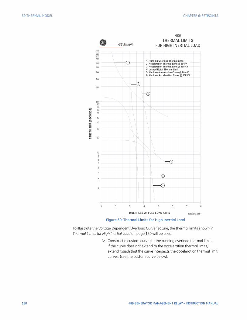
180 489 GENERATOR MANAGEMENT RELAY – INSTRUCTION MANUAL
S9 THERMAL MODEL CHAPTER 6: SETPOINTS
Figure 50: Thermal Limits for High Inertial Load
To illustrate the Voltage Dependent Overload Curve feature, the thermal limits shown in Thermal Limits for High Inertial Load on page 180 will be used.
Construct a custom curve for the running overload thermal limit. If the curve does not extend to the acceleration thermal limits, extend it such that the curve intersects the acceleration thermal limit curves. (see the custom curve below).
489THERMAL LIMITS
FOR HIGH INERTIAL LOAD
808826A3.CDR
1
1 2 3 4 5 6 7 8
2
3
4
5
6
7
8
9
10
20
30
40
50
60
70
80
90
100
TIM
ET
OT
RIP
(SE
CO
ND
S)
MULTIPLES OF FULL LOAD AMPS
200
300
400
500
600
700
800
900
1000
1
2
3
4
6
5
1- Running Overload Thermal Limit
2- Acceleration Thermal Limit @ 80%V
3- Acceleration Thermal Limit @ 100%V
4- Locked Rotor Thermal Limit
5- Machine Acceleration Curve @ 80% V
6- Machine Acceleration Curve @ 100%V
GE Multilin
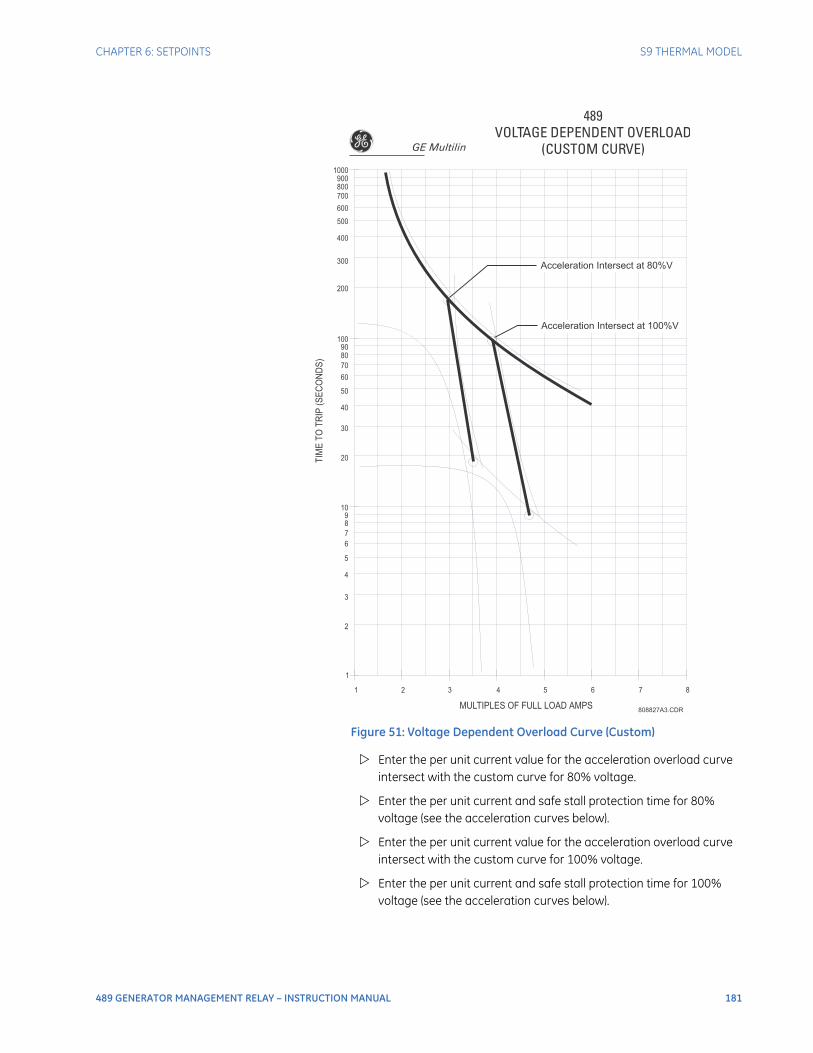
CHAPTER 6: SETPOINTS S9 THERMAL MODEL
489 GENERATOR MANAGEMENT RELAY – INSTRUCTION MANUAL 181
Figure 51: Voltage Dependent Overload Curve (Custom)
Enter the per unit current value for the acceleration overload curve intersect with the custom curve for 80% voltage.
Enter the per unit current and safe stall protection time for 80% voltage (see the acceleration curves below).
Enter the per unit current value for the acceleration overload curve intersect with the custom curve for 100% voltage.
Enter the per unit current and safe stall protection time for 100% voltage (see the acceleration curves below).
489VOLTAGE DEPENDENT OVERLOAD
(CUSTOM CURVE)
808827A3.CDR
1
1 2 3 4 5 6 7 8
2
3
4
5
6
7
8
9
10
20
30
40
50
60
70
80
90
100
TIM
ET
OT
RIP
(SE
CO
ND
S)
MULTIPLES OF FULL LOAD AMPS
200
300
400
500
600
700
800
900
1000
Acceleration Intersect at 80%V
Acceleration Intersect at 100%V
GE Multilin
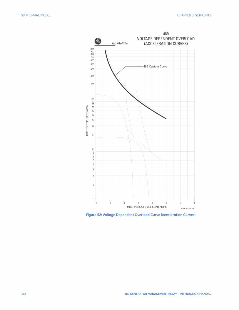
182 489 GENERATOR MANAGEMENT RELAY – INSTRUCTION MANUAL
S9 THERMAL MODEL CHAPTER 6: SETPOINTS
Figure 52: Voltage Dependent Overload Curve (Acceleration Curves)
489VOLTAGE DEPENDENT OVERLOAD
(ACCELERATION CURVES)
808828A3.CDR
1
1 2 3 4 5 6 7 8
2
3
4
5
6
7
8
9
10
20
30
40
50
60
70
80
90
100
TIM
ET
OT
RIP
(SE
CO
ND
S)
MULTIPLES OF FULL LOAD AMPS
200
300
400
500
600
700
800
900
1000
489 Custom Curve
GE Multilin

CHAPTER 6: SETPOINTS S9 THERMAL MODEL
489 GENERATOR MANAGEMENT RELAY – INSTRUCTION MANUAL 183
The 489 takes the information provided and create protection curves for any voltage between the minimum and 100%. For values above the voltage in question, the 489 extrapolates the safe stall protection curve to 110% voltage. This current level is calculated by taking the locked rotor current at 100% voltage and multiplying by 1.10. For trip times above the 110% voltage level, the trip time of 110% will be used (see the figure below).
Figure 53: Voltage Dependent Overload Protection Curves
489VOLTAGE DEPENDENT
OVERLOAD PROTECTION CURVES
808831A3.CDR
1
1 2 3 4 5 6 7 8
2
3
4
5
6
7
8
9
10
20
30
40
50
60
70
80
90
100
TIM
ET
OT
RIP
(SE
CO
ND
S)
MULTIPLES OF FULL LOAD AMPS
200
300
400
500
600
700
800
900
1000
Acceleration Intersect at 80%V
Custom Curve
Acceleration Intersect at 100%V
Safe Stall Time at 80%V,
80%V Stall Current
Safe Stall Time at 100%V,
100%V Stall Current
Safe Stall Points
Extrapolated to 110%V
GE Multilin
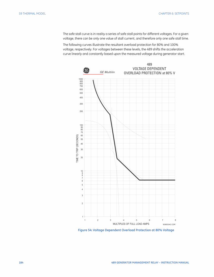
184 489 GENERATOR MANAGEMENT RELAY – INSTRUCTION MANUAL
S9 THERMAL MODEL CHAPTER 6: SETPOINTS
The safe stall curve is in reality a series of safe stall points for different voltages. For a given voltage, there can be only one value of stall current, and therefore only one safe stall time.
The following curves illustrate the resultant overload protection for 80% and 100% voltage, respectively. For voltages between these levels, the 489 shifts the acceleration curve linearly and constantly based upon the measured voltage during generator start.
Figure 54: Voltage Dependent Overload Protection at 80% Voltage
489VOLTAGE DEPENDENT
OVERLOAD PROTECTION at 80% V
808830A3.CDR
1
1 2 3 4 5 6 7 8
2
3
4
5
6
7
8
9
10
20
30
40
50
60
70
80
90
100
TIM
ET
OT
RIP
(SE
CO
ND
S)
MULTIPLES OF FULL LOAD AMPS
200
300
400
500
600
700
800
900
1000
GE Multilin
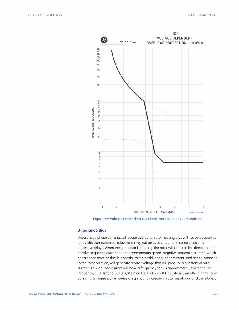
CHAPTER 6: SETPOINTS S9 THERMAL MODEL
489 GENERATOR MANAGEMENT RELAY – INSTRUCTION MANUAL 185
Figure 55: Voltage Dependent Overload Protection at 100% Voltage
Unbalance Bias
Unbalanced phase currents will cause additional rotor heating that will not be accounted for by electromechanical relays and may not be accounted for in some electronic protective relays. When the generator is running, the rotor will rotate in the direction of the positive sequence current at near synchronous speed. Negative sequence current, which has a phase rotation that is opposite to the positive sequence current, and hence, opposite to the rotor rotation, will generate a rotor voltage that will produce a substantial rotor current. This induced current will have a frequency that is approximately twice the line frequency, 100 Hz for a 50 Hz system or 120 Hz for a 60 Hz system. Skin effect in the rotor bars at this frequency will cause a significant increase in rotor resistance and therefore, a
489VOLTAGE DEPENDENT
OVERLOAD PROTECTION at 100% V
808829A3.CDR
1
1 2 3 4 5 6 7 8
2
3
4
5
6
7
8
9
10
20
30
40
50
60
70
80
90
100
TIM
ET
OT
RIP
(SE
CO
ND
S)
MULTIPLES OF FULL LOAD AMPS
200
300
400
500
600
700
800
900
1000
GE Multilin
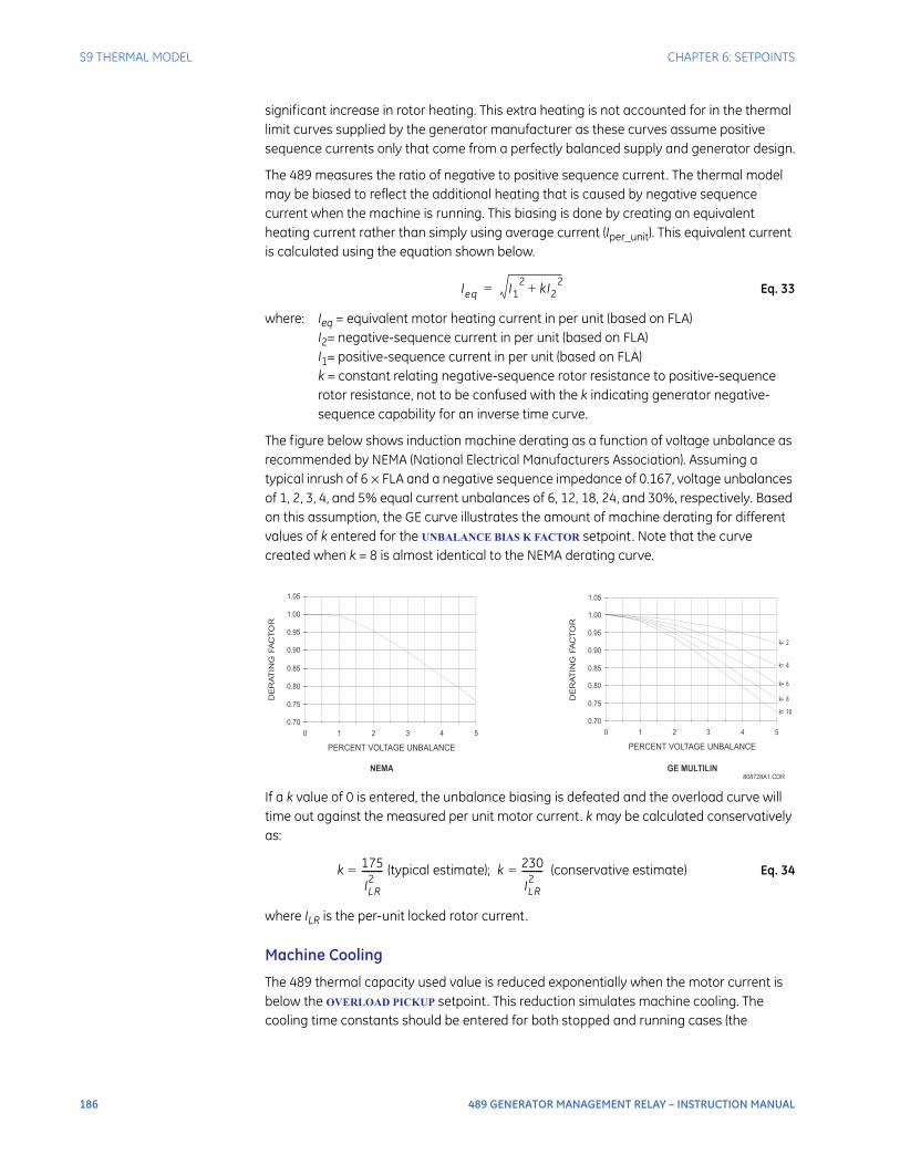
186 489 GENERATOR MANAGEMENT RELAY – INSTRUCTION MANUAL
S9 THERMAL MODEL CHAPTER 6: SETPOINTS
significant increase in rotor heating. This extra heating is not accounted for in the thermal limit curves supplied by the generator manufacturer as these curves assume positive sequence currents only that come from a perfectly balanced supply and generator design.
The 489 measures the ratio of negative to positive sequence current. The thermal model may be biased to reflect the additional heating that is caused by negative sequence current when the machine is running. This biasing is done by creating an equivalent heating current rather than simply using average current (Iper_unit). This equivalent current is calculated using the equation shown below.
Eq. 33
where: Ieq = equivalent motor heating current in per unit (based on FLA)I2= negative-sequence current in per unit (based on FLA)I1= positive-sequence current in per unit (based on FLA)k = constant relating negative-sequence rotor resistance to positive-sequence rotor resistance, not to be confused with the k indicating generator negative-sequence capability for an inverse time curve.
The figure below shows induction machine derating as a function of voltage unbalance as recommended by NEMA (National Electrical Manufacturers Association). Assuming a typical inrush of 6 × FLA and a negative sequence impedance of 0.167, voltage unbalances of 1, 2, 3, 4, and 5% equal current unbalances of 6, 12, 18, 24, and 30%, respectively. Based on this assumption, the GE curve illustrates the amount of machine derating for different values of k entered for the UNBALANCE BIAS K FACTOR setpoint. Note that the curve created when k = 8 is almost identical to the NEMA derating curve.
If a k value of 0 is entered, the unbalance biasing is defeated and the overload curve will time out against the measured per unit motor current. k may be calculated conservatively as:
Eq. 34
where ILR is the per-unit locked rotor current.
Machine Cooling
The 489 thermal capacity used value is reduced exponentially when the motor current is below the OVERLOAD PICKUP setpoint. This reduction simulates machine cooling. The cooling time constants should be entered for both stopped and running cases (the
Ieq I12 kI2
2+=
808728A1.CDR
0.70
0.75
0.80
0.85
0.90
0.95
1.00
1.05
0 1 2 3 4 5
PERCENT VOLTAGE UNBALANCE
DE
RAT
ING
FA
CT
OR
k=2
k=4
k=6
k=8
k=100.70
0.75
0.80
0.85
0.90
0.95
1.00
1.05
0 1 2 3 4 5
PERCENT VOLTAGE UNBALANCE
DE
RA
TIN
GFA
CTO
R
NEMA GE MULTILIN
k 175
ILR2
---------= (typical estimate); k 230
ILR2
---------= (conservative estimate)
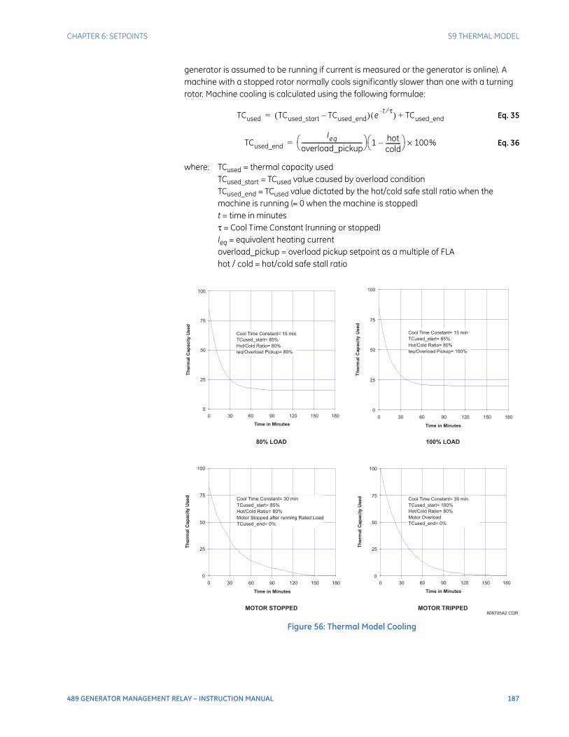
CHAPTER 6: SETPOINTS S9 THERMAL MODEL
489 GENERATOR MANAGEMENT RELAY – INSTRUCTION MANUAL 187
generator is assumed to be running if current is measured or the generator is online). A machine with a stopped rotor normally cools significantly slower than one with a turning rotor. Machine cooling is calculated using the following formulae:
Eq. 35
Eq. 36
where: TCused = thermal capacity usedTCused_start = TCused value caused by overload conditionTCused_end = TCused value dictated by the hot/cold safe stall ratio when the machine is running (= 0 when the machine is stopped)t = time in minutesτ = Cool Time Constant (running or stopped)Ieq = equivalent heating currentoverload_pickup = overload pickup setpoint as a multiple of FLAhot / cold = hot/cold safe stall ratio
Figure 56: Thermal Model Cooling
TCused TCused_start TCused_end–( ) e t τ⁄–( ) TCused_end+=
TCused_end
Ieq
overload_pickup----------------------------------------- 1 hot
cold----------–
100%×=
808705A2.CDR
0
25
50
75
100
0 30 60 90 120 150 180
Time in Minutes
Th
erm
al
Cap
acit
yU
sed
Cool Time Constant= 15 min
TCused_start= 85%
Hot/Cold Ratio= 80%
Ieq/Overload Pickup= 100%
0
25
50
75
100
0 30 60 90 120 150 180
Time in Minutes
Th
erm
al
Cap
acit
yU
sed
Cool Time Constant= 15 min
TCused_start= 85%
Hot/Cold Ratio= 80%
Ieq/Overload Pickup= 80%
0
25
50
75
100
0 30 60 90 120 150 180
Time in Minutes
Th
erm
al
Cap
acit
yU
sed
Cool Time Constant= 30 min
TCused_start= 85%
Hot/Cold Ratio= 80%
Motor Stopped after running Rated Load
TCused_end= 0%
0
25
50
75
100
0 30 60 90 120 150 180
Time in Minutes
Th
erm
al
Cap
acit
yU
sed Cool Time Constant= 30 min
TCused_start= 100%
Hot/Cold Ratio= 80%
Motor Overload
TCused_end= 0%
MOTOR TRIPPED
100% LOAD
MOTOR STOPPED
80% LOAD

188 489 GENERATOR MANAGEMENT RELAY – INSTRUCTION MANUAL
S9 THERMAL MODEL CHAPTER 6: SETPOINTS
Hot/Cold Safe Stall Ratio
When thermal limit information is available for both a hot and cold machine, the 489 thermal model will adapt for the conditions if the HOT/COLD SAFE STALL RATIO is programmed. The value entered for this setpoint dictates the level of thermal capacity used that the relay will settle at for levels of current that are below the OVERLOAD PICKUP
LEVEL. When the generator is running at a level below the OVERLOAD PICKUP LEVEL, the thermal capacity used will rise or fall to a value based on the average phase current and the entered HOT/COLD SAFE STALL RATIO. Thermal capacity used will either rise at a fixed rate of 5% per minute or fall as dictated by the running cool time constant.
Eq. 37
where: TCused_end = Thermal Capacity Used if Iper_unit remains steady stateIeq = equivalent generator heating currenthot/cold = HOT/COLD SAFE STALL RATIO setpoint
The hot/cold safe stall ratio may be determined from the thermal limit curves, if provided, or the hot and cold safe stall times. Simply divide the hot safe stall time by the cold safe stall time. If hot and cold times are not provided, there can be no differentiation and the HOT/COLD SAFE STALL RATIO should be entered as “1.00”.
RTD Bias
The thermal replica created by the features described in the sections above operates as a complete and independent model. However, the thermal overload curves are based solely on measured current, assuming a normal 40°C ambient and normal machine cooling. If there is an unusually high ambient temperature, or if machine cooling is blocked, generator temperature will increase. If the stator has embedded RTDs, the 489 RTD bias feature should be used to correct the thermal model.
The RTD bias feature is a two part curve, constructed using 3 points. If the maximum stator RTD temperature is below the RTD BIAS MINIMUM setpoint (typically 40°C), no biasing occurs. If the maximum stator RTD temperature is above the RTD BIAS MAXIMUM setpoint (typically at the stator insulation rating or slightly higher), then the thermal memory is fully biased and thermal capacity is forced to 100% used. At values in between, the present thermal capacity used created by the overload curve and other elements of the thermal model, is compared to the RTD Bias thermal capacity used from the RTD Bias curve. If the RTD Bias thermal capacity used value is higher, then that value is used from that point onward. The RTD BIAS CENTER POINT should be set at the rated running temperature of the machine. The 489 automatically determines the thermal capacity used value for the center point using the HOT/COLD SAFE STALL RATIO setpoint.
Eq. 38
At temperatures less that the RTD Bias Center temperature,
Eq. 39
At temperatures greater than the RTD Bias Center temperature,
Eq. 40
TCused_end Ieq 1 hotcold----------–
100%××=
TCused at RBC 1 hotcold----------–
100%×=
RTD_Bias_TCused
Tempactual Tempmin–
Tempcenter Tempmin–------------------------------------------------------ TCused at RBC×=
RTD_Bias_TCused
Tempactual Tempcenter–
Tempmax Tempcenter–---------------------------------------------------------- 100 TCused at RBC–( )× TCused at RBC+=
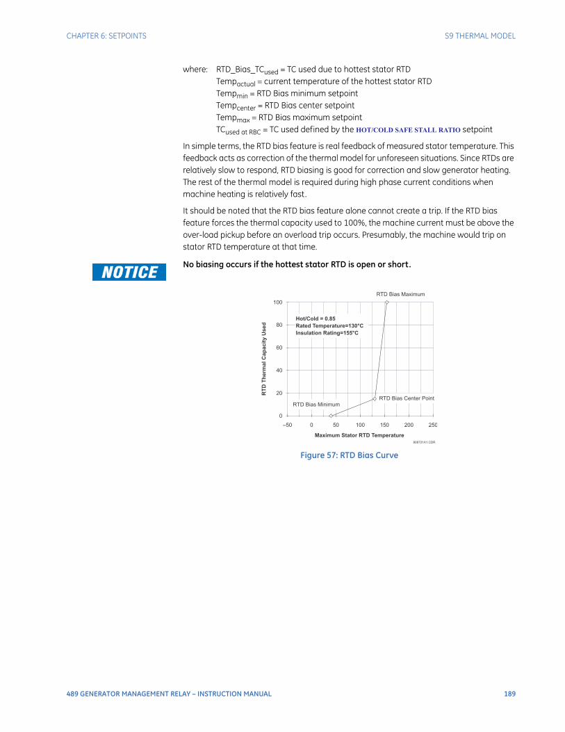
CHAPTER 6: SETPOINTS S9 THERMAL MODEL
489 GENERATOR MANAGEMENT RELAY – INSTRUCTION MANUAL 189
where: RTD_Bias_TCused = TC used due to hottest stator RTDTempactual = current temperature of the hottest stator RTDTempmin = RTD Bias minimum setpointTempcenter = RTD Bias center setpointTempmax = RTD Bias maximum setpointTCused at RBC = TC used defined by the HOT/COLD SAFE STALL RATIO setpoint
In simple terms, the RTD bias feature is real feedback of measured stator temperature. This feedback acts as correction of the thermal model for unforeseen situations. Since RTDs are relatively slow to respond, RTD biasing is good for correction and slow generator heating. The rest of the thermal model is required during high phase current conditions when machine heating is relatively fast.
It should be noted that the RTD bias feature alone cannot create a trip. If the RTD bias feature forces the thermal capacity used to 100%, the machine current must be above the over-load pickup before an overload trip occurs. Presumably, the machine would trip on stator RTD temperature at that time.
No biasing occurs if the hottest stator RTD is open or short.
Figure 57: RTD Bias Curve
808721A1.CDR
Maximum Stator RTD Temperature
0
20
40
60
80
100
–50 0 50 100 150 200 250
RTD Bias Maximum
RTD Bias Center Point
RTD Bias Minimum
Hot/Cold = 0.85
Rated Temperature=130°C
Insulation Rating=155°C
RT
DT
he
rm
al
Ca
pa
cit
yU
se
d
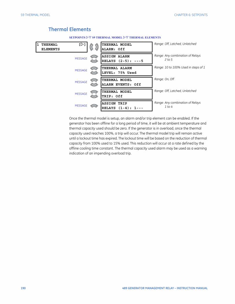
190 489 GENERATOR MANAGEMENT RELAY – INSTRUCTION MANUAL
S9 THERMAL MODEL CHAPTER 6: SETPOINTS
Thermal ElementsSETPOINTS S9 THERMAL MODEL THERMAL ELEMENTS
Once the thermal model is setup, an alarm and/or trip element can be enabled. If the generator has been offline for a long period of time, it will be at ambient temperature and thermal capacity used should be zero. If the generator is in overload, once the thermal capacity used reaches 100%, a trip will occur. The thermal model trip will remain active until a lockout time has expired. The lockout time will be based on the reduction of thermal capacity from 100% used to 15% used. This reduction will occur at a rate defined by the offline cooling time constant. The thermal capacity used alarm may be used as a warning indication of an impending overload trip.
1 THERMAL []ELEMENTS
THERMAL MODELALARM: Off
Range: Off, Latched, Unlatched
MESSAGEASSIGN ALARMRELAYS (2-5): ---5
Range: Any combination of Relays2 to 5
MESSAGETHERMAL ALARMLEVEL: 75% Used
Range: 10 to 100% Used in steps of 1
MESSAGETHERMAL MODELALARM EVENTS: Off
Range: On, Off
MESSAGETHERMAL MODELTRIP: Off
Range: Off, Latched, Unlatched
MESSAGEASSIGN TRIPRELAYS (1-4): 1---
Range: Any combination of Relays1 to 4
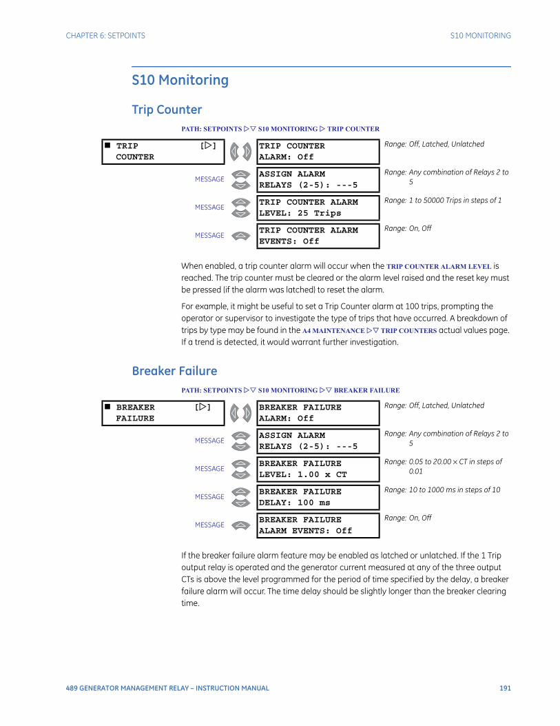
CHAPTER 6: SETPOINTS S10 MONITORING
489 GENERATOR MANAGEMENT RELAY – INSTRUCTION MANUAL 191
S10 Monitoring
Trip CounterPATH: SETPOINTS S10 MONITORING TRIP COUNTER
When enabled, a trip counter alarm will occur when the TRIP COUNTER ALARM LEVEL is reached. The trip counter must be cleared or the alarm level raised and the reset key must be pressed (if the alarm was latched) to reset the alarm.
For example, it might be useful to set a Trip Counter alarm at 100 trips, prompting the operator or supervisor to investigate the type of trips that have occurred. A breakdown of trips by type may be found in the A4 MAINTENANCE TRIP COUNTERS actual values page. If a trend is detected, it would warrant further investigation.
Breaker FailurePATH: SETPOINTS S10 MONITORING BREAKER FAILURE
If the breaker failure alarm feature may be enabled as latched or unlatched. If the 1 Trip output relay is operated and the generator current measured at any of the three output CTs is above the level programmed for the period of time specified by the delay, a breaker failure alarm will occur. The time delay should be slightly longer than the breaker clearing time.
TRIP []COUNTER
TRIP COUNTERALARM: Off
Range: Off, Latched, Unlatched
MESSAGEASSIGN ALARMRELAYS (2-5): ---5
Range: Any combination of Relays 2 to 5
MESSAGETRIP COUNTER ALARMLEVEL: 25 Trips
Range: 1 to 50000 Trips in steps of 1
MESSAGETRIP COUNTER ALARMEVENTS: Off
Range: On, Off
BREAKER []FAILURE
BREAKER FAILUREALARM: Off
Range: Off, Latched, Unlatched
MESSAGEASSIGN ALARMRELAYS (2-5): ---5
Range: Any combination of Relays 2 to 5
MESSAGEBREAKER FAILURELEVEL: 1.00 x CT
Range: 0.05 to 20.00 × CT in steps of 0.01
MESSAGEBREAKER FAILUREDELAY: 100 ms
Range: 10 to 1000 ms in steps of 10
MESSAGEBREAKER FAILUREALARM EVENTS: Off
Range: On, Off
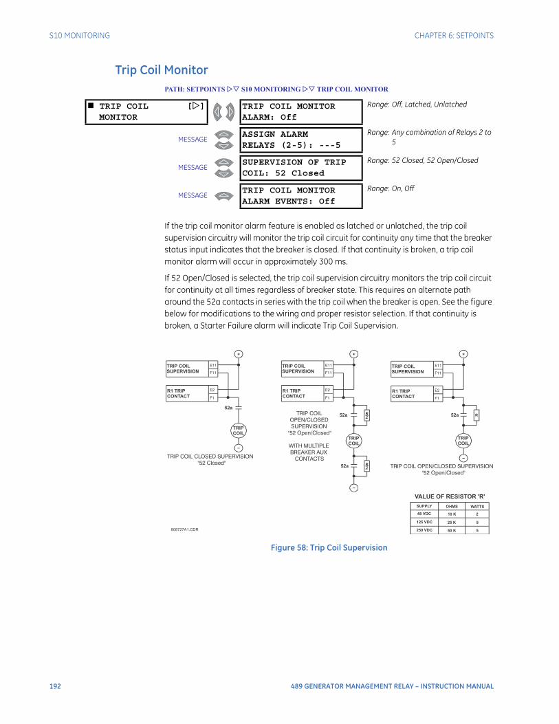
192 489 GENERATOR MANAGEMENT RELAY – INSTRUCTION MANUAL
S10 MONITORING CHAPTER 6: SETPOINTS
Trip Coil MonitorPATH: SETPOINTS S10 MONITORING TRIP COIL MONITOR
If the trip coil monitor alarm feature is enabled as latched or unlatched, the trip coil supervision circuitry will monitor the trip coil circuit for continuity any time that the breaker status input indicates that the breaker is closed. If that continuity is broken, a trip coil monitor alarm will occur in approximately 300 ms.
If 52 Open/Closed is selected, the trip coil supervision circuitry monitors the trip coil circuit for continuity at all times regardless of breaker state. This requires an alternate path around the 52a contacts in series with the trip coil when the breaker is open. See the figure below for modifications to the wiring and proper resistor selection. If that continuity is broken, a Starter Failure alarm will indicate Trip Coil Supervision.
Figure 58: Trip Coil Supervision
TRIP COIL []MONITOR
TRIP COIL MONITORALARM: Off
Range: Off, Latched, Unlatched
MESSAGEASSIGN ALARMRELAYS (2-5): ---5
Range: Any combination of Relays 2 to 5
MESSAGESUPERVISION OF TRIPCOIL: 52 Closed
Range: 52 Closed, 52 Open/Closed
MESSAGETRIP COIL MONITORALARM EVENTS: Off
Range: On, Off
808727A1.CDR
VALUE OF RESISTOR 'R'
SUPPLY OHMS WATTS
48 VDC
125 VDC
250 VDC
10 K
25 K
50 K
2
5
5
TRIP
COIL
TRIP COIL
SUPERVISION
R1 TRIP
CONTACT
F11
E2
F1
E11
52a
TRIP COIL CLOSED SUPERVISION"52 Closed"
TRIP COIL
SUPERVISION
R1 TRIP
CONTACT
TRIP
COIL
F11
E2
F1
E11
52a
TRIP COIL OPEN/CLOSED SUPERVISION"52 Open/Closed"
52a
TRIP
COIL
TRIP COIL
SUPERVISION
R1 TRIP
CONTACT
F11
E2
F1
E11
52a
TRIP COILOPEN/CLOSEDSUPERVISION
"52 Open/Closed"
WITH MULTIPLEBREAKER AUX
CONTACTS
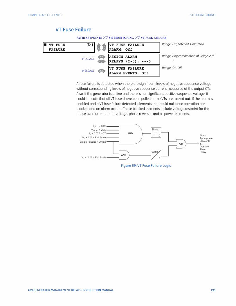
CHAPTER 6: SETPOINTS S10 MONITORING
489 GENERATOR MANAGEMENT RELAY – INSTRUCTION MANUAL 193
VT Fuse FailurePATH: SETPOINTS S10 MONITORING VT FUSE FAILURE
A fuse failure is detected when there are significant levels of negative sequence voltage without corresponding levels of negative sequence current measured at the output CTs. Also, if the generator is online and there is not significant positive sequence voltage, it could indicate that all VT fuses have been pulled or the VTs are racked out. If the alarm is enabled and a VT fuse failure detected, elements that could nuisance operation are blocked and an alarm occurs. These blocked elements include voltage restraint for the phase overcurrent, undervoltage, phase reversal, and all power elements.
Figure 59: VT Fuse Failure Logic
VT FUSE []FAILURE
VT FUSE FAILUREALARM: Off
Range: Off, Latched, Unlatched
MESSAGEASSIGN ALARMRELAYS (2-5): ---5
Range: Any combination of Relays 2 to 5
MESSAGEVT FUSE FAILUREALARM EVENTS: Off
Range: On, Off
99ms
99ms
Block
Appropriate
Elements
&
Operate
Alarm
Relay
I / I < 20%2 1
V / V > 25%2 1
I > 0.075 x CT1
V > 0.05 x Full Scale1
Breaker Status = Online
V < 0.05 Full Scale1
× 0
0AND
OR
AND

194 489 GENERATOR MANAGEMENT RELAY – INSTRUCTION MANUAL
S10 MONITORING CHAPTER 6: SETPOINTS
DemandPATH: SETPOINTS S10 MONITORING CURRENT DEMAND...
CURRENT []DEMAND
CURRENT DEMANDPERIOD: 15 min.
Range: 5 to 90 min. in steps of 1
MESSAGECURRENT DEMANDALARM: Off
Range: Off, Latched, Unlatched
MESSAGEASSIGN ALARMRELAYS (2-5): ---5
Range: Any combination of Relays 2 to 5
MESSAGECURRENT DEMANDLIMIT: 1.25 x FLA
Range: 0.10 to 20.00 × FLA in steps of 0.01
MESSAGECURRENT DEMANDALARM EVENTS: Off
Range: On, Off
MW DEMAND [] MW DEMANDPERIOD: 15 min.
Range: 5 to 90 min. in steps of 1
MESSAGEMW DEMANDALARM: Off
Range: Off, Latched, Unlatched
MESSAGEASSIGN ALARMRELAYS (2-5): ---5
Range: Any combination of Relays 2 to 5
MESSAGEMW DEMANDLIMIT: 1.25 x Rated
Range: 0.10 to 2.00 × Rated in steps of 0.01
MESSAGEMW DEMANDALARM EVENTS: Off
Range: On, Off
Mvar DEMAND [] Mvar DEMANDPERIOD: 15 min.
Range: 5 to 90 min. in steps of 1
MESSAGEMvar DEMANDALARM: Off
Range: Off, Latched, Unlatched
MESSAGEASSIGN ALARMRELAYS (2-5): ---5
Range: Any combination of Relays 2 to 5
MESSAGEMvar DEMANDLIMIT: 1.25 x Rated
Range: 0.10 to 2.00 × Rated in steps of 0.01
MESSAGEMvar DEMANDALARM EVENTS: Off
Range: On, Off
MVA DEMAND [] MVA DEMANDPERIOD: 15 min.
Range: 5 to 90 min. in steps of 1
MESSAGEMVA DEMANDALARM: Off
Range: Off, Latched, Unlatched
MESSAGEASSIGN ALARMRELAYS (2-5): ---5
Range: Any combination of Relays 2 to 5
MESSAGEMVA DEMANDLIMIT: 1.25 x Rated
Range: 0.10 to 2.00 × Rated in steps of 0.01
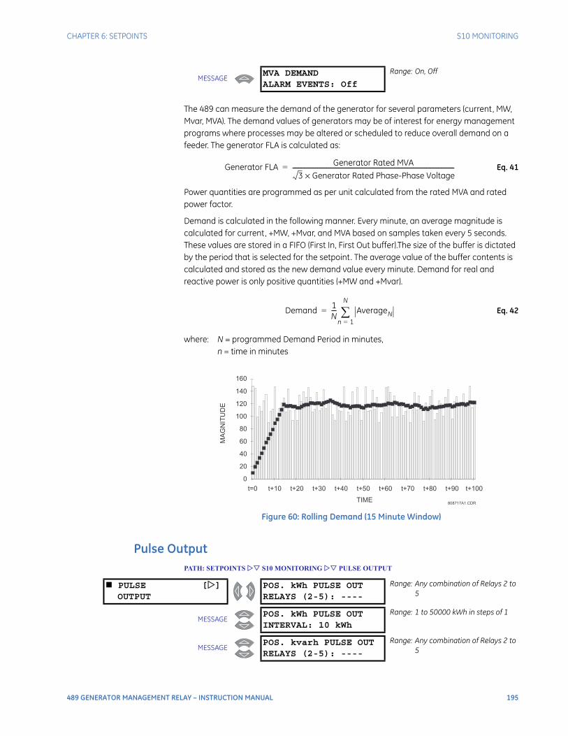
CHAPTER 6: SETPOINTS S10 MONITORING
489 GENERATOR MANAGEMENT RELAY – INSTRUCTION MANUAL 195
The 489 can measure the demand of the generator for several parameters (current, MW, Mvar, MVA). The demand values of generators may be of interest for energy management programs where processes may be altered or scheduled to reduce overall demand on a feeder. The generator FLA is calculated as:
Eq. 41
Power quantities are programmed as per unit calculated from the rated MVA and rated power factor.
Demand is calculated in the following manner. Every minute, an average magnitude is calculated for current, +MW, +Mvar, and MVA based on samples taken every 5 seconds. These values are stored in a FIFO (First In, First Out buffer).The size of the buffer is dictated by the period that is selected for the setpoint. The average value of the buffer contents is calculated and stored as the new demand value every minute. Demand for real and reactive power is only positive quantities (+MW and +Mvar).
Eq. 42
where: N = programmed Demand Period in minutes,n = time in minutes
Figure 60: Rolling Demand (15 Minute Window)
Pulse OutputPATH: SETPOINTS S10 MONITORING PULSE OUTPUT
MESSAGEMVA DEMANDALARM EVENTS: Off
Range: On, Off
Generator FLA Generator Rated MVA
3 Generator Rated Phase-Phase Voltage×--------------------------------------------------------------------------------------------------------------=
Demand 1N--- AverageN
n 1=
N
=
808717A1.CDRTIME
0
20
40
60
80
100
120
140
160
t=0 t+10 t+20 t+30 t+40 t+50 t+60 t+70 t+80 t+90 t+100
MA
GN
ITU
DE
PULSE []OUTPUT
POS. kWh PULSE OUTRELAYS (2-5): ----
Range: Any combination of Relays 2 to 5
MESSAGEPOS. kWh PULSE OUTINTERVAL: 10 kWh
Range: 1 to 50000 kWh in steps of 1
MESSAGEPOS. kvarh PULSE OUTRELAYS (2-5): ----
Range: Any combination of Relays 2 to 5
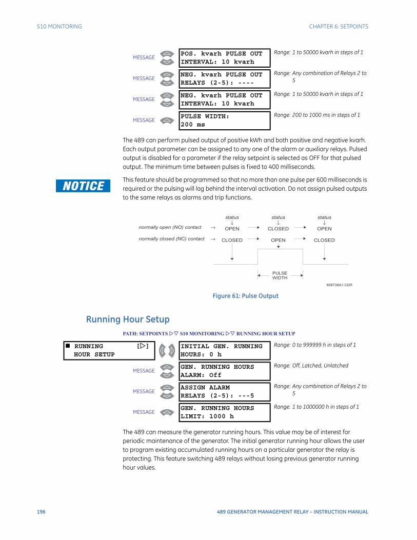
196 489 GENERATOR MANAGEMENT RELAY – INSTRUCTION MANUAL
S10 MONITORING CHAPTER 6: SETPOINTS
The 489 can perform pulsed output of positive kWh and both positive and negative kvarh. Each output parameter can be assigned to any one of the alarm or auxiliary relays. Pulsed output is disabled for a parameter if the relay setpoint is selected as OFF for that pulsed output. The minimum time between pulses is fixed to 400 milliseconds.
This feature should be programmed so that no more than one pulse per 600 milliseconds is required or the pulsing will lag behind the interval activation. Do not assign pulsed outputs to the same relays as alarms and trip functions.
Figure 61: Pulse Output
Running Hour SetupPATH: SETPOINTS S10 MONITORING RUNNING HOUR SETUP
The 489 can measure the generator running hours. This value may be of interest for periodic maintenance of the generator. The initial generator running hour allows the user to program existing accumulated running hours on a particular generator the relay is protecting. This feature switching 489 relays without losing previous generator running hour values.
MESSAGEPOS. kvarh PULSE OUTINTERVAL: 10 kvarh
Range: 1 to 50000 kvarh in steps of 1
MESSAGENEG. kvarh PULSE OUTRELAYS (2-5): ----
Range: Any combination of Relays 2 to 5
MESSAGENEG. kvarh PULSE OUTINTERVAL: 10 kvarh
Range: 1 to 50000 kvarh in steps of 1
MESSAGEPULSE WIDTH:200 ms
Range: 200 to 1000 ms in steps of 1
808738A1.CDR
PULSE
WIDTH
normally open (NO) contact →
normally closed (NC) contact →
status
↓OPEN
CLOSED
status
↓CLOSED
OPEN
status
↓OPEN
CLOSED
RUNNING []HOUR SETUP
INITIAL GEN. RUNNINGHOURS: 0 h
Range: 0 to 999999 h in steps of 1
MESSAGEGEN. RUNNING HOURSALARM: Off
Range: Off, Latched, Unlatched
MESSAGEASSIGN ALARMRELAYS (2-5): ---5
Range: Any combination of Relays 2 to 5
MESSAGEGEN. RUNNING HOURSLIMIT: 1000 h
Range: 1 to 1000000 h in steps of 1
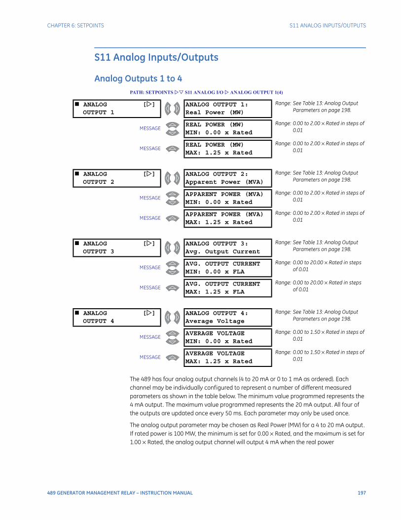
CHAPTER 6: SETPOINTS S11 ANALOG INPUTS/OUTPUTS
489 GENERATOR MANAGEMENT RELAY – INSTRUCTION MANUAL 197
S11 Analog Inputs/Outputs
Analog Outputs 1 to 4PATH: SETPOINTS S11 ANALOG I/O ANALOG OUTPUT 1(4)
The 489 has four analog output channels (4 to 20 mA or 0 to 1 mA as ordered). Each channel may be individually configured to represent a number of different measured parameters as shown in the table below. The minimum value programmed represents the 4 mA output. The maximum value programmed represents the 20 mA output. All four of the outputs are updated once every 50 ms. Each parameter may only be used once.
The analog output parameter may be chosen as Real Power (MW) for a 4 to 20 mA output. If rated power is 100 MW, the minimum is set for 0.00 × Rated, and the maximum is set for 1.00 × Rated, the analog output channel will output 4 mA when the real power
ANALOG []OUTPUT 1
ANALOG OUTPUT 1:Real Power (MW)
Range: See Table 13: Analog Output Parameters on page 198.
MESSAGEREAL POWER (MW)MIN: 0.00 x Rated
Range: 0.00 to 2.00 × Rated in steps of 0.01
MESSAGEREAL POWER (MW)MAX: 1.25 x Rated
Range: 0.00 to 2.00 × Rated in steps of 0.01
ANALOG []OUTPUT 2
ANALOG OUTPUT 2:Apparent Power (MVA)
Range: See Table 13: Analog Output Parameters on page 198.
MESSAGEAPPARENT POWER (MVA)MIN: 0.00 x Rated
Range: 0.00 to 2.00 × Rated in steps of 0.01
MESSAGEAPPARENT POWER (MVA)MAX: 1.25 x Rated
Range: 0.00 to 2.00 × Rated in steps of 0.01
ANALOG []OUTPUT 3
ANALOG OUTPUT 3:Avg. Output Current
Range: See Table 13: Analog Output Parameters on page 198.
MESSAGEAVG. OUTPUT CURRENTMIN: 0.00 x FLA
Range: 0.00 to 20.00 × Rated in steps of 0.01
MESSAGEAVG. OUTPUT CURRENTMAX: 1.25 x FLA
Range: 0.00 to 20.00 × Rated in steps of 0.01
ANALOG []OUTPUT 4
ANALOG OUTPUT 4:Average Voltage
Range: See Table 13: Analog Output Parameters on page 198.
MESSAGEAVERAGE VOLTAGEMIN: 0.00 x Rated
Range: 0.00 to 1.50 × Rated in steps of 0.01
MESSAGEAVERAGE VOLTAGEMAX: 1.25 x Rated
Range: 0.00 to 1.50 × Rated in steps of 0.01
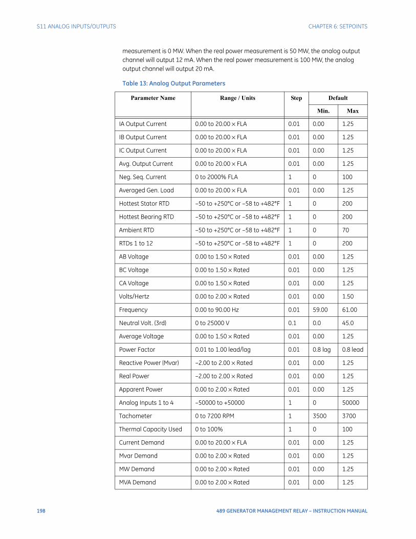
198 489 GENERATOR MANAGEMENT RELAY – INSTRUCTION MANUAL
S11 ANALOG INPUTS/OUTPUTS CHAPTER 6: SETPOINTS
measurement is 0 MW. When the real power measurement is 50 MW, the analog output channel will output 12 mA. When the real power measurement is 100 MW, the analog output channel will output 20 mA.
Table 13: Analog Output Parameters
Parameter Name Range / Units Step Default
Min. Max
IA Output Current 0.00 to 20.00 × FLA 0.01 0.00 1.25
IB Output Current 0.00 to 20.00 × FLA 0.01 0.00 1.25
IC Output Current 0.00 to 20.00 × FLA 0.01 0.00 1.25
Avg. Output Current 0.00 to 20.00 × FLA 0.01 0.00 1.25
Neg. Seq. Current 0 to 2000% FLA 1 0 100
Averaged Gen. Load 0.00 to 20.00 × FLA 0.01 0.00 1.25
Hottest Stator RTD –50 to +250°C or –58 to +482°F 1 0 200
Hottest Bearing RTD –50 to +250°C or –58 to +482°F 1 0 200
Ambient RTD –50 to +250°C or –58 to +482°F 1 0 70
RTDs 1 to 12 –50 to +250°C or –58 to +482°F 1 0 200
AB Voltage 0.00 to 1.50 × Rated 0.01 0.00 1.25
BC Voltage 0.00 to 1.50 × Rated 0.01 0.00 1.25
CA Voltage 0.00 to 1.50 × Rated 0.01 0.00 1.25
Volts/Hertz 0.00 to 2.00 × Rated 0.01 0.00 1.50
Frequency 0.00 to 90.00 Hz 0.01 59.00 61.00
Neutral Volt. (3rd) 0 to 25000 V 0.1 0.0 45.0
Average Voltage 0.00 to 1.50 × Rated 0.01 0.00 1.25
Power Factor 0.01 to 1.00 lead/lag 0.01 0.8 lag 0.8 lead
Reactive Power (Mvar) –2.00 to 2.00 × Rated 0.01 0.00 1.25
Real Power –2.00 to 2.00 × Rated 0.01 0.00 1.25
Apparent Power 0.00 to 2.00 × Rated 0.01 0.00 1.25
Analog Inputs 1 to 4 –50000 to +50000 1 0 50000
Tachometer 0 to 7200 RPM 1 3500 3700
Thermal Capacity Used 0 to 100% 1 0 100
Current Demand 0.00 to 20.00 × FLA 0.01 0.00 1.25
Mvar Demand 0.00 to 2.00 × Rated 0.01 0.00 1.25
MW Demand 0.00 to 2.00 × Rated 0.01 0.00 1.25
MVA Demand 0.00 to 2.00 × Rated 0.01 0.00 1.25
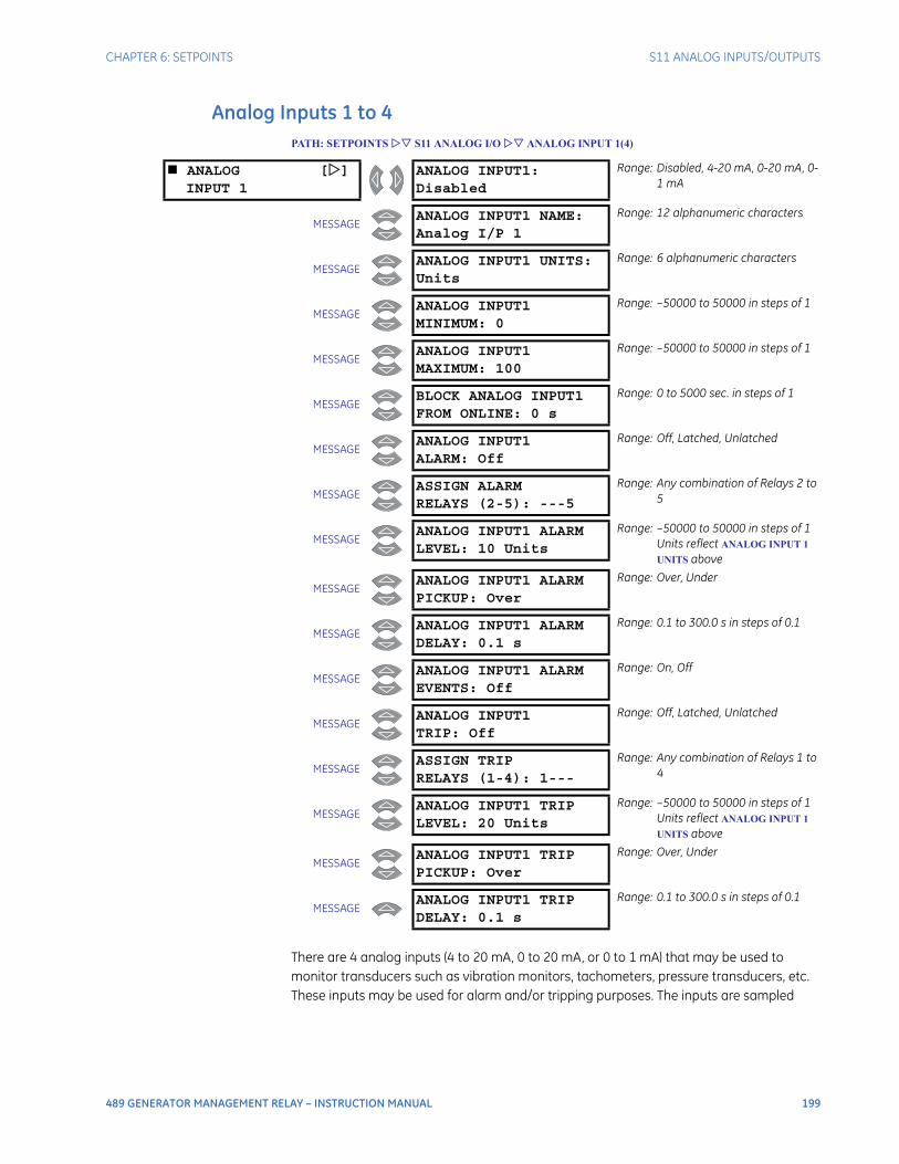
CHAPTER 6: SETPOINTS S11 ANALOG INPUTS/OUTPUTS
489 GENERATOR MANAGEMENT RELAY – INSTRUCTION MANUAL 199
Analog Inputs 1 to 4PATH: SETPOINTS S11 ANALOG I/O ANALOG INPUT 1(4)
There are 4 analog inputs (4 to 20 mA, 0 to 20 mA, or 0 to 1 mA) that may be used to monitor transducers such as vibration monitors, tachometers, pressure transducers, etc. These inputs may be used for alarm and/or tripping purposes. The inputs are sampled
ANALOG []INPUT 1
ANALOG INPUT1:Disabled
Range: Disabled, 4-20 mA, 0-20 mA, 0-1 mA
MESSAGEANALOG INPUT1 NAME:Analog I/P 1
Range: 12 alphanumeric characters
MESSAGEANALOG INPUT1 UNITS:Units
Range: 6 alphanumeric characters
MESSAGEANALOG INPUT1MINIMUM: 0
Range: –50000 to 50000 in steps of 1
MESSAGEANALOG INPUT1MAXIMUM: 100
Range: –50000 to 50000 in steps of 1
MESSAGEBLOCK ANALOG INPUT1FROM ONLINE: 0 s
Range: 0 to 5000 sec. in steps of 1
MESSAGEANALOG INPUT1ALARM: Off
Range: Off, Latched, Unlatched
MESSAGEASSIGN ALARMRELAYS (2-5): ---5
Range: Any combination of Relays 2 to 5
MESSAGEANALOG INPUT1 ALARMLEVEL: 10 Units
Range: –50000 to 50000 in steps of 1Units reflect ANALOG INPUT 1
UNITS above
MESSAGEANALOG INPUT1 ALARMPICKUP: Over
Range: Over, Under
MESSAGEANALOG INPUT1 ALARMDELAY: 0.1 s
Range: 0.1 to 300.0 s in steps of 0.1
MESSAGEANALOG INPUT1 ALARMEVENTS: Off
Range: On, Off
MESSAGEANALOG INPUT1TRIP: Off
Range: Off, Latched, Unlatched
MESSAGEASSIGN TRIPRELAYS (1-4): 1---
Range: Any combination of Relays 1 to 4
MESSAGEANALOG INPUT1 TRIPLEVEL: 20 Units
Range: –50000 to 50000 in steps of 1Units reflect ANALOG INPUT 1
UNITS above
MESSAGEANALOG INPUT1 TRIPPICKUP: Over
Range: Over, Under
MESSAGEANALOG INPUT1 TRIPDELAY: 0.1 s
Range: 0.1 to 300.0 s in steps of 0.1

200 489 GENERATOR MANAGEMENT RELAY – INSTRUCTION MANUAL
S11 ANALOG INPUTS/OUTPUTS CHAPTER 6: SETPOINTS
every 50 ms. The level of the analog input is also available over the communications port. With the EnerVista 489 Setup program, the level of the transducer may be trended and graphed.
Before the input may be used, it must be configured. A name may be assigned for the input, units may be assigned, and a minimum and maxi-mum value must be assigned. Also, the trip and alarm features may be blocked until the generator is online for a specified time delay. If the block time is 0 seconds, there is no block and the trip and alarm features will be active when the generator is offline or online. If a time is programmed other than 0 seconds, the feature will be disabled when the generator is offline and also from the time the machine is placed online until the time entered expires. Once the input is setup, both the trip and alarm features may be configured. In addition to programming a level and time delay, the PICKUP setpoint may be used to dictate whether the feature picks up when the measured value is over or under the level.
If a vibration transducer is to be used, program the name as “Vib Monitor”, the units as “mm/s”, the minimum as “0”, the maximum as “25”, and the Block From Online as “0 s”. Set the alarm for a reasonable level slightly higher than the normal vibration level. Program a delay of “3 s” and the pickup as “Over”.
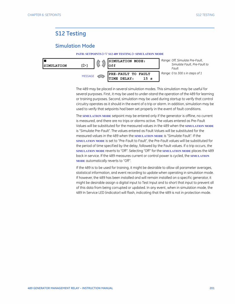
CHAPTER 6: SETPOINTS S12 TESTING
489 GENERATOR MANAGEMENT RELAY – INSTRUCTION MANUAL 201
S12 Testing
Simulation ModePATH: SETPOINTS S12 489 TESTING SIMULATION MODE
The 489 may be placed in several simulation modes. This simulation may be useful for several purposes. First, it may be used to under-stand the operation of the 489 for learning or training purposes. Second, simulation may be used during startup to verify that control circuitry operates as it should in the event of a trip or alarm. In addition, simulation may be used to verify that setpoints had been set properly in the event of fault conditions.
The SIMULATION MODE setpoint may be entered only if the generator is offline, no current is measured, and there are no trips or alarms active. The values entered as Pre-Fault Values will be substituted for the measured values in the 489 when the SIMULATION MODE is “Simulate Pre-Fault”. The values entered as Fault Values will be substituted for the measured values in the 489 when the SIMULATION MODE is “Simulate Fault”. If the SIMULATION MODE is set to “Pre-Fault to Fault”, the Pre-Fault values will be substituted for the period of time specified by the delay, followed by the Fault values. If a trip occurs, the SIMULATION MODE reverts to “Off”. Selecting “Off” for the SIMULATION MODE places the 489 back in service. If the 489 measures current or control power is cycled, the SIMULATION
MODE automatically reverts to “Off”.
If the 489 is to be used for training, it might be desirable to allow all parameter averages, statistical information, and event recording to update when operating in simulation mode. If however, the 489 has been installed and will remain installed on a specific generator, it might be desirable assign a digital input to Test Input and to short that input to prevent all of this data from being corrupted or updated. In any event, when in simulation mode, the 489 In Service LED (indicator) will flash, indicating that the 489 is not in protection mode.
SIMULATION []
SIMULATION MODE:Off
Range: Off, Simulate Pre-Fault, Simulate Fault, Pre-Fault to Fault
MESSAGEPRE-FAULT TO FAULTTIME DELAY: 15 s
Range: 0 to 300 s in steps of 1

202 489 GENERATOR MANAGEMENT RELAY – INSTRUCTION MANUAL
S12 TESTING CHAPTER 6: SETPOINTS
Pre-Fault SetupPATH: SETPOINTS S12 489 TESTING PRE-FAULT SETUP
The values entered under Pre-Fault Values will be substituted for the measured values in the 489 when the SIMULATION MODE is “Simulate Pre-Fault”.
PRE-FAULT []SETUP
PRE-FAULT IphaseOUTPUT: 0.00 x CT
Range: 0.00 to 20.00 × CT in steps of 0.01
MESSAGEPRE-FAULT VOLTAGESPHASE-N: 1.00 x Rated
Range: 0.00 to 1.50 × Rated in steps of 0.01. Enter as a phase-to-neutral quantity.
MESSAGEPRE-FAULT CURRENTLAGS VOLTAGE: 0°
Range: 0 to 359° in steps of 1
MESSAGEPRE-FAULT IphaseNEUTRAL: 0.00 x CT
Range: 0.00 to 20.00 × CT in steps of 0.01 180° phase shift with respect to Iphase OUTPUT
MESSAGEPRE-FAULT CURRENTGROUND: 0.00 x CT
Range: 0.00 to 20.00 × CT in steps of 0.01. CT is either XXX:1 or 50:0.025
MESSAGEPRE-FAULT VOLTAGENEUTRAL: 0 Vsec
Range 0.0 to 100.0 Vsec in steps of 0.1Fundamental value only in secondary units
MESSAGEPRE-FAULT STATORRTD TEMP: 40°C
Range: –50 to 250°C in steps of 1
MESSAGEPRE-FAULT BEARINGRTD TEMP: 40°C
Range: –50 to 250°C in steps of 1
MESSAGEPRE-FAULT OTHERRTD TEMP: 40°C
Range: –50 to 250°C in steps of 1
MESSAGEPRE-FAULT AMBIENTRTD TEMP: 40°C
Range: –50 to 250°C in steps of 1
MESSAGEPRE-FAULT SYSTEMFREQUENCY: 60.0 Hz
Range: 5.0 to 90.0 Hz in steps of 0.1
MESSAGEPRE-FAULT ANALOGINPUT 1: 0%
Range: 0 to 100% in steps of 1
MESSAGEPRE-FAULT ANALOGINPUT 2: 0%
Range: 0 to 100% in steps of 1
MESSAGEPRE-FAULT ANALOGINPUT 3: 0%
Range: 0 to 100% in steps of 1
MESSAGEPRE-FAULT ANALOGINPUT 4: 0%
Range: 0 to 100% in steps of 1
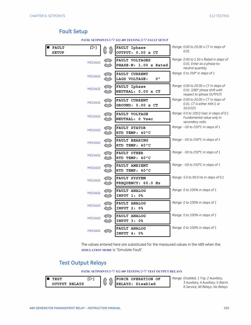
CHAPTER 6: SETPOINTS S12 TESTING
489 GENERATOR MANAGEMENT RELAY – INSTRUCTION MANUAL 203
Fault SetupPATH: SETPOINTS S12 489 TESTING FAULT SETUP
The values entered here are substituted for the measured values in the 489 when the SIMULATION MODE is “Simulate Fault”.
Test Output RelaysPATH: SETPOINTS S12 489 TESTING TEST OUTPUT RELAYS
FAULT []SETUP
FAULT IphaseOUTPUT: 0.00 x CT
Range: 0.00 to 20.00 × CT in steps of 0.01
MESSAGEFAULT VOLTAGESPHASE-N: 1.00 x Rated
Range: 0.00 to 1.50 × Rated in steps of 0.01. Enter as a phase-to-neutral quantity.
MESSAGEFAULT CURRENTLAGS VOLTAGE: 0°
Range: 0 to 359° in steps of 1
MESSAGEFAULT IphaseNEUTRAL: 0.00 x CT
Range: 0.00 to 20.00 × CT in steps of 0.01. (180° phase shift with respect to Iphase OUTPUT)
MESSAGEFAULT CURRENTGROUND: 0.00 x CT
Range: 0.00 to 20.00 × CT in steps of 0.01. CT is either XXX:1 or 50:0.025
MESSAGEFAULT VOLTAGENEUTRAL: 0 Vsec
Range: 0.0 to 100.0 Vsec in steps of 0.1Fundamental value only in secondary volts
MESSAGEFAULT STATORRTD TEMP: 40°C
Range: –50 to 250°C in steps of 1
MESSAGEFAULT BEARINGRTD TEMP: 40°C
Range: –50 to 250°C in steps of 1
MESSAGEFAULT OTHERRTD TEMP: 40°C
Range: –50 to 250°C in steps of 1
MESSAGEFAULT AMBIENTRTD TEMP: 40°C
Range: –50 to 250°C in steps of 1
MESSAGEFAULT SYSTEMFREQUENCY: 60.0 Hz
Range: 5.0 to 90.0 Hz in steps of 0.1
MESSAGEFAULT ANALOGINPUT 1: 0%
Range: 0 to 100% in steps of 1
MESSAGEFAULT ANALOGINPUT 2: 0%
Range: 0 to 100% in steps of 1
MESSAGEFAULT ANALOGINPUT 3: 0%
Range: 0 to 100% in steps of 1
MESSAGEFAULT ANALOGINPUT 4: 0%
Range: 0 to 100% in steps of 1
TEST []OUTPUT RELAYS
FORCE OPERATION OFRELAYS: Disabled
Range: Disabled, 1 Trip, 2 Auxiliary, 3 Auxiliary, 4 Auxiliary, 5 Alarm, 6 Service, All Relays, No Relays
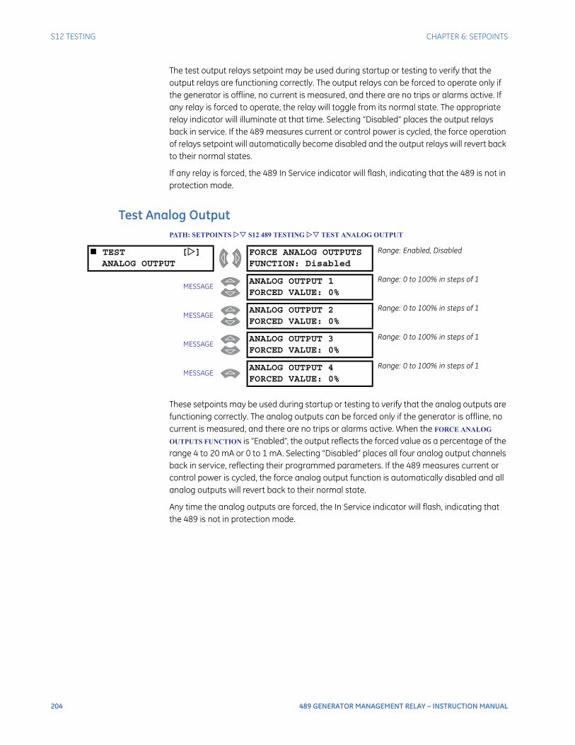
204 489 GENERATOR MANAGEMENT RELAY – INSTRUCTION MANUAL
S12 TESTING CHAPTER 6: SETPOINTS
The test output relays setpoint may be used during startup or testing to verify that the output relays are functioning correctly. The output relays can be forced to operate only if the generator is offline, no current is measured, and there are no trips or alarms active. If any relay is forced to operate, the relay will toggle from its normal state. The appropriate relay indicator will illuminate at that time. Selecting “Disabled” places the output relays back in service. If the 489 measures current or control power is cycled, the force operation of relays setpoint will automatically become disabled and the output relays will revert back to their normal states.
If any relay is forced, the 489 In Service indicator will flash, indicating that the 489 is not in protection mode.
Test Analog OutputPATH: SETPOINTS S12 489 TESTING TEST ANALOG OUTPUT
These setpoints may be used during startup or testing to verify that the analog outputs are functioning correctly. The analog outputs can be forced only if the generator is offline, no current is measured, and there are no trips or alarms active. When the FORCE ANALOG
OUTPUTS FUNCTION is “Enabled”, the output reflects the forced value as a percentage of the range 4 to 20 mA or 0 to 1 mA. Selecting “Disabled” places all four analog output channels back in service, reflecting their programmed parameters. If the 489 measures current or control power is cycled, the force analog output function is automatically disabled and all analog outputs will revert back to their normal state.
Any time the analog outputs are forced, the In Service indicator will flash, indicating that the 489 is not in protection mode.
TEST []ANALOG OUTPUT
FORCE ANALOG OUTPUTSFUNCTION: Disabled
Range: Enabled, Disabled
MESSAGEANALOG OUTPUT 1FORCED VALUE: 0%
Range: 0 to 100% in steps of 1
MESSAGEANALOG OUTPUT 2FORCED VALUE: 0%
Range: 0 to 100% in steps of 1
MESSAGEANALOG OUTPUT 3FORCED VALUE: 0%
Range: 0 to 100% in steps of 1
MESSAGEANALOG OUTPUT 4FORCED VALUE: 0%
Range: 0 to 100% in steps of 1
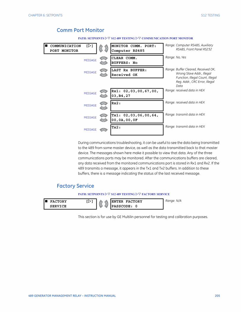
CHAPTER 6: SETPOINTS S12 TESTING
489 GENERATOR MANAGEMENT RELAY – INSTRUCTION MANUAL 205
Comm Port MonitorPATH: SETPOINTS S12 489 TESTING COMMUNICATION PORT MONITOR
During communications troubleshooting, it can be useful to see the data being transmitted to the 489 from some master device, as well as the data transmitted back to that master device. The messages shown here make it possible to view that data. Any of the three communications ports may be monitored. After the communications buffers are cleared, any data received from the monitored communications port is stored in Rx1 and Rx2. If the 489 transmits a message, it appears in the Tx1 and Tx2 buffers. In addition to these buffers, there is a message indicating the status of the last received message.
Factory ServicePATH: SETPOINTS S12 489 TESTING FACTORY SERVICE
This section is for use by GE Multilin personnel for testing and calibration purposes.
COMMUNICATION []PORT MONITOR
MONITOR COMM. PORT:Computer RS485
Range: Computer RS485, Auxiliary RS485, Front Panel RS232
MESSAGECLEAR COMM.BUFFERS: No
Range: No, Yes
MESSAGELAST Rx BUFFER:Received OK
Range: Buffer Cleared, Received OK, Wrong Slave Addr., Illegal Function, Illegal Count, Illegal Reg. Addr., CRC Error, Illegal Data
MESSAGERx1: 02,03,00,67,00,03,B4,27
Range: received data in HEX
MESSAGERx2: Range: received data in HEX
MESSAGETx1: 02,03,06,00,64,00,0A,00,0F
Range: transmit data in HEX
MESSAGETx2: Range: transmit data in HEX
FACTORY []SERVICE
ENTER FACTORYPASSCODE: 0
Range: N/A

206 489 GENERATOR MANAGEMENT RELAY – INSTRUCTION MANUAL
S12 TESTING CHAPTER 6: SETPOINTS

489 GENERATOR MANAGEMENT RELAY – INSTRUCTION MANUAL 207
489 Generator Management Relay
Chapter 7: Actual Values
Actual Values
Overview
Actual Values Main MenuThe actual values message map is shown below.
ACTUAL VALUES []A1 STATUS
NETWORK STATUS []
See page 210.
MESSAGE GENERATOR []
STATUSSee page 210.
MESSAGE LAST TRIP []
DATASee page 211.
MESSAGE ALARM []
STATUSSee page 212.
MESSAGE TRIP []
PICKUPSSee page 215.
MESSAGE ALARM []
PICKUPSSee page 218.
MESSAGE DIGITAL []
INPUTSSee page 221.
MESSAGE REAL TIME []
CLOCKSee page 221.
MESSAGEEND OF PAGE

208 489 GENERATOR MANAGEMENT RELAY – INSTRUCTION MANUAL
OVERVIEW CHAPTER 7: ACTUAL VALUES
ACTUAL VALUES []A2 METERING DATA
CURRENT []METERING
See page 222.
MESSAGE VOLTAGE []
METERINGSee page 223.
MESSAGE POWER []
METERINGSee page 224.
MESSAGE TEMPERATURE []
See page 225.
MESSAGE DEMAND []
METERINGSee page 226.
MESSAGE ANALOG []
INPUTSSee page 226.
MESSAGE SPEED []
See page 227.
MESSAGEEND OF PAGE
ACTUAL VALUES []A3 LEARNED DATA
PARAMETER []AVERAGES
See page 228.
MESSAGE RTD []
MAXIMUMSSee page 228.
MESSAGE ANALOG INPUT []
MIN/MAXSee page 229.
MESSAGEEND OF PAGE
ACTUAL VALUES []A4 MAINTENANCE
TRIP []COUNTERS
See page 230.
MESSAGE GENERAL []
COUNTERSSee page 232.
MESSAGE TIMERS []
See page 232.
MESSAGEEND OF PAGE
ACTUAL VALUES []A5 EVENT RECORD
E255 []<Cause>
See page 233.
MESSAGE E254 []
<Cause>See page 233.
↓
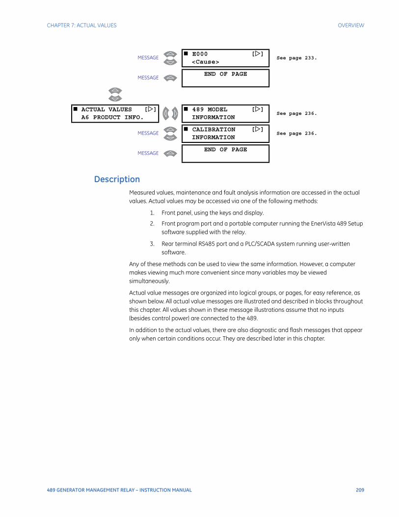
CHAPTER 7: ACTUAL VALUES OVERVIEW
489 GENERATOR MANAGEMENT RELAY – INSTRUCTION MANUAL 209
DescriptionMeasured values, maintenance and fault analysis information are accessed in the actual values. Actual values may be accessed via one of the following methods:
1. Front panel, using the keys and display.
2. Front program port and a portable computer running the EnerVista 489 Setup software supplied with the relay.
3. Rear terminal RS485 port and a PLC/SCADA system running user-written software.
Any of these methods can be used to view the same information. However, a computer makes viewing much more convenient since many variables may be viewed simultaneously.
Actual value messages are organized into logical groups, or pages, for easy reference, as shown below. All actual value messages are illustrated and described in blocks throughout this chapter. All values shown in these message illustrations assume that no inputs (besides control power) are connected to the 489.
In addition to the actual values, there are also diagnostic and flash messages that appear only when certain conditions occur. They are described later in this chapter.
MESSAGE E000 []
<Cause>See page 233.
MESSAGEEND OF PAGE
ACTUAL VALUES []A6 PRODUCT INFO.
489 MODEL []INFORMATION
See page 236.
MESSAGE CALIBRATION []
INFORMATIONSee page 236.
MESSAGEEND OF PAGE
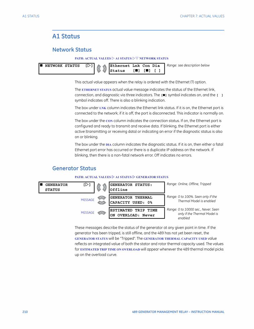
210 489 GENERATOR MANAGEMENT RELAY – INSTRUCTION MANUAL
A1 STATUS CHAPTER 7: ACTUAL VALUES
A1 Status
Network StatusPATH: ACTUAL VALUES A1 STATUS NETWORK STATUS
This actual value appears when the relay is ordered with the Ethernet (T) option.
The ETHERNET STATUS actual value message indicates the status of the Ethernet link, connection, and diagnostic via three indicators. The [] symbol indicates on, and the [ ] symbol indicates off. There is also a blinking indication.
The box under LNK column indicates the Ethernet link status. If it is on, the Ethernet port is connected to the network; if it is off, the port is disconnected. This indicator is normally on.
The box under the CON column indicates the connection status. If on, the Ethernet port is configured and ready to transmit and receive data. If blinking, the Ethernet port is either active (transmitting or receiving data) or indicating an error if the diagnostic status is also on or blinking.
The box under the DIA column indicates the diagnostic status. If it is on, then either a fatal Ethernet port error has occurred or there is a duplicate IP address on the network. If blinking, then there is a non-fatal network error. Off indicates no errors.
Generator StatusPATH: ACTUAL VALUES A1 STATUS GENERATOR STATUS
These messages describe the status of the generator at any given point in time. If the generator has been tripped, is still offline, and the 489 has not yet been reset, the GENERATOR STATUS will be “Tripped”. The GENERATOR THERMAL CAPACITY USED value reflects an integrated value of both the stator and rotor thermal capacity used. The values for ESTIMATED TRIP TIME ON OVERLOAD will appear whenever the 489 thermal model picks up on the overload curve.
NETWORK STATUS [] Ethernet Lnk Con DiaStatus [] [] [ ]
Range: see description below
GENERATOR []STATUS
GENERATOR STATUS:Offline
Range: Online, Offline, Tripped
MESSAGEGENERATOR THERMALCAPACITY USED: 0%
Range: 0 to 100%. Seen only if the Thermal Model is enabled
MESSAGEESTIMATED TRIP TIMEON OVERLOAD: Never
Range: 0 to 10000 sec., Never. Seen only if the Thermal Model is enabled
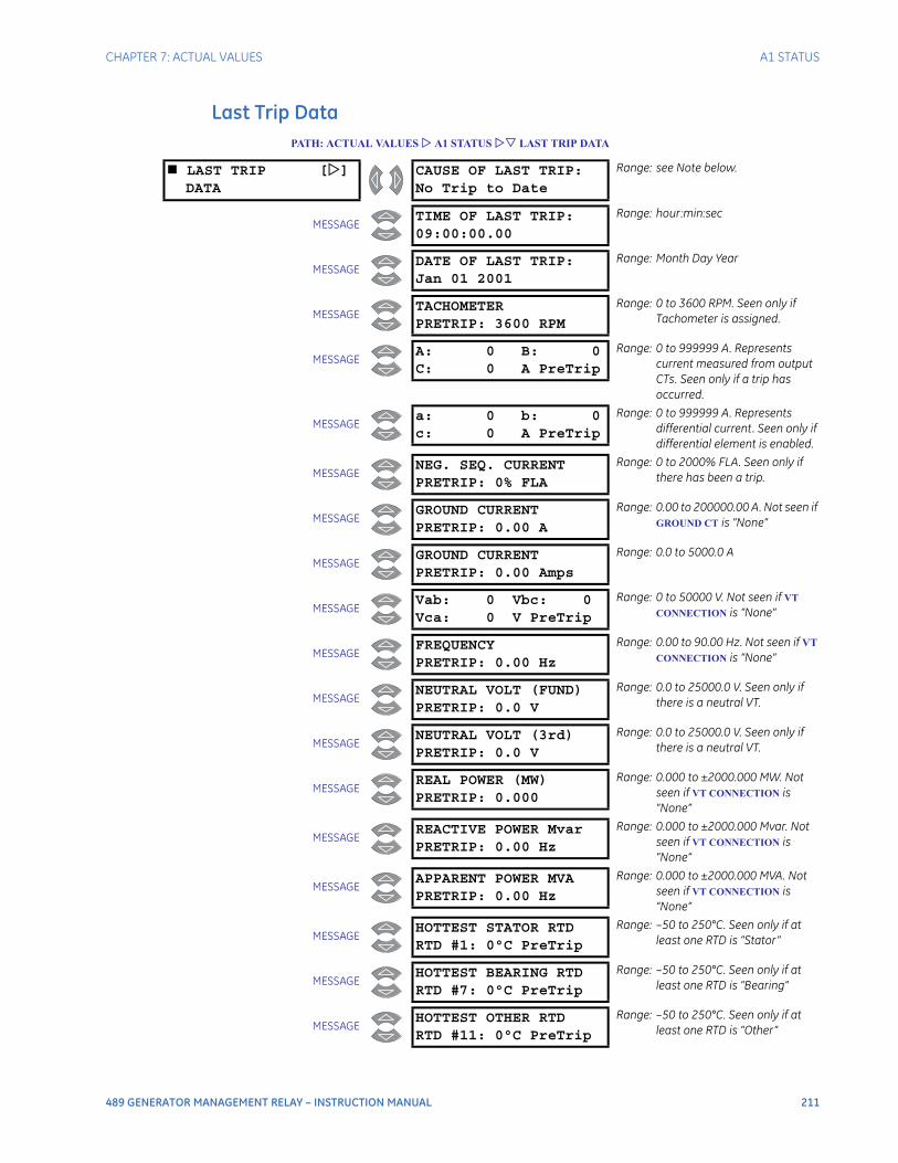
CHAPTER 7: ACTUAL VALUES A1 STATUS
489 GENERATOR MANAGEMENT RELAY – INSTRUCTION MANUAL 211
Last Trip DataPATH: ACTUAL VALUES A1 STATUS LAST TRIP DATA
LAST TRIP []DATA
CAUSE OF LAST TRIP:No Trip to Date
Range: see Note below.
MESSAGETIME OF LAST TRIP:09:00:00.00
Range: hour:min:sec
MESSAGEDATE OF LAST TRIP:Jan 01 2001
Range: Month Day Year
MESSAGETACHOMETERPRETRIP: 3600 RPM
Range: 0 to 3600 RPM. Seen only if Tachometer is assigned.
MESSAGEA: 0 B: 0C: 0 A PreTrip
Range: 0 to 999999 A. Represents current measured from output CTs. Seen only if a trip has occurred.
MESSAGEa: 0 b: 0c: 0 A PreTrip
Range: 0 to 999999 A. Represents differential current. Seen only if differential element is enabled.
MESSAGENEG. SEQ. CURRENTPRETRIP: 0% FLA
Range: 0 to 2000% FLA. Seen only if there has been a trip.
MESSAGEGROUND CURRENTPRETRIP: 0.00 A
Range: 0.00 to 200000.00 A. Not seen if GROUND CT is “None”
MESSAGEGROUND CURRENTPRETRIP: 0.00 Amps
Range: 0.0 to 5000.0 A
MESSAGEVab: 0 Vbc: 0Vca: 0 V PreTrip
Range: 0 to 50000 V. Not seen if VT
CONNECTION is “None”
MESSAGEFREQUENCYPRETRIP: 0.00 Hz
Range: 0.00 to 90.00 Hz. Not seen if VT
CONNECTION is “None”
MESSAGENEUTRAL VOLT (FUND)PRETRIP: 0.0 V
Range: 0.0 to 25000.0 V. Seen only if there is a neutral VT.
MESSAGENEUTRAL VOLT (3rd)PRETRIP: 0.0 V
Range: 0.0 to 25000.0 V. Seen only if there is a neutral VT.
MESSAGEREAL POWER (MW)PRETRIP: 0.000
Range: 0.000 to ±2000.000 MW. Not seen if VT CONNECTION is “None”
MESSAGEREACTIVE POWER MvarPRETRIP: 0.00 Hz
Range: 0.000 to ±2000.000 Mvar. Not seen if VT CONNECTION is “None”
MESSAGEAPPARENT POWER MVAPRETRIP: 0.00 Hz
Range: 0.000 to ±2000.000 MVA. Not seen if VT CONNECTION is “None”
MESSAGEHOTTEST STATOR RTDRTD #1: 0°C PreTrip
Range: –50 to 250°C. Seen only if at least one RTD is “Stator”
MESSAGEHOTTEST BEARING RTDRTD #7: 0°C PreTrip
Range: –50 to 250°C. Seen only if at least one RTD is “Bearing”
MESSAGEHOTTEST OTHER RTDRTD #11: 0°C PreTrip
Range: –50 to 250°C. Seen only if at least one RTD is “Other”
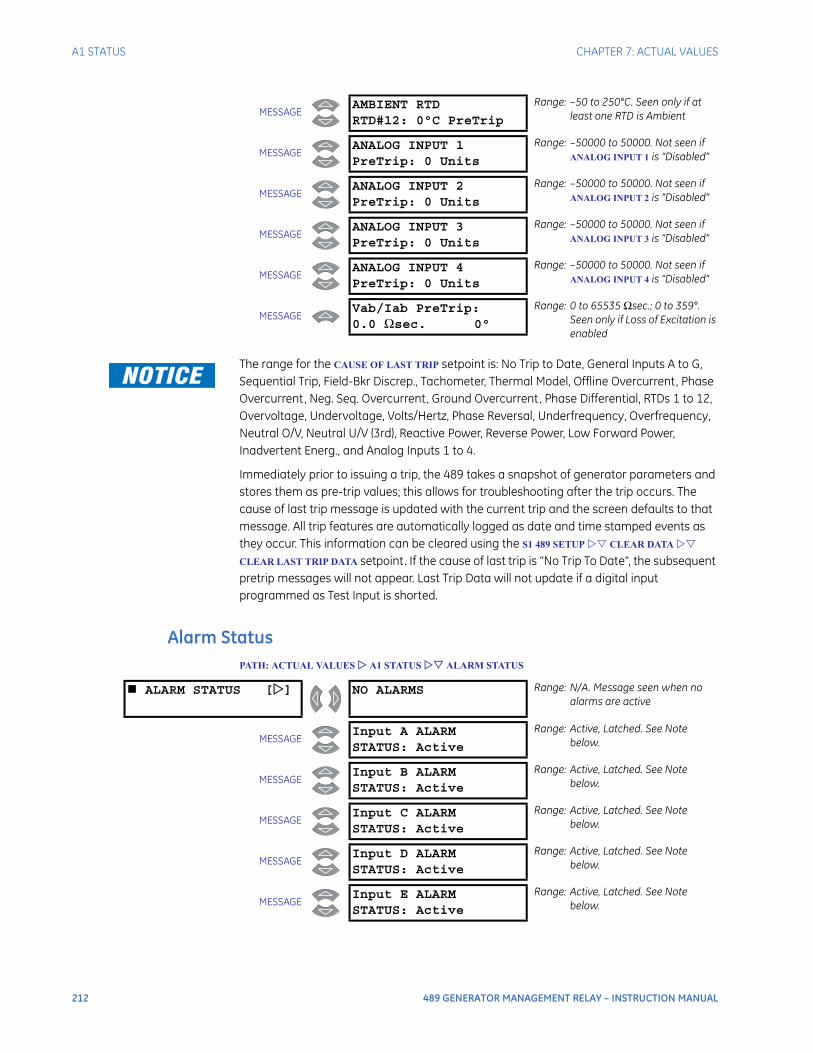
212 489 GENERATOR MANAGEMENT RELAY – INSTRUCTION MANUAL
A1 STATUS CHAPTER 7: ACTUAL VALUES
The range for the CAUSE OF LAST TRIP setpoint is: No Trip to Date, General Inputs A to G, Sequential Trip, Field-Bkr Discrep., Tachometer, Thermal Model, Offline Overcurrent, Phase Overcurrent, Neg. Seq. Overcurrent, Ground Overcurrent, Phase Differential, RTDs 1 to 12, Overvoltage, Undervoltage, Volts/Hertz, Phase Reversal, Underfrequency, Overfrequency, Neutral O/V, Neutral U/V (3rd), Reactive Power, Reverse Power, Low Forward Power, Inadvertent Energ., and Analog Inputs 1 to 4.
Immediately prior to issuing a trip, the 489 takes a snapshot of generator parameters and stores them as pre-trip values; this allows for troubleshooting after the trip occurs. The cause of last trip message is updated with the current trip and the screen defaults to that message. All trip features are automatically logged as date and time stamped events as they occur. This information can be cleared using the S1 489 SETUP CLEAR DATA
CLEAR LAST TRIP DATA setpoint. If the cause of last trip is “No Trip To Date”, the subsequent pretrip messages will not appear. Last Trip Data will not update if a digital input programmed as Test Input is shorted.
Alarm StatusPATH: ACTUAL VALUES A1 STATUS ALARM STATUS
MESSAGEAMBIENT RTDRTD#12: 0°C PreTrip
Range: –50 to 250°C. Seen only if at least one RTD is Ambient
MESSAGEANALOG INPUT 1PreTrip: 0 Units
Range: –50000 to 50000. Not seen if ANALOG INPUT 1 is “Disabled”
MESSAGEANALOG INPUT 2PreTrip: 0 Units
Range: –50000 to 50000. Not seen if ANALOG INPUT 2 is “Disabled”
MESSAGEANALOG INPUT 3PreTrip: 0 Units
Range: –50000 to 50000. Not seen if ANALOG INPUT 3 is “Disabled”
MESSAGEANALOG INPUT 4PreTrip: 0 Units
Range: –50000 to 50000. Not seen if ANALOG INPUT 4 is “Disabled”
MESSAGEVab/Iab PreTrip:0.0 Ωsec. 0°
Range: 0 to 65535 Ωsec.; 0 to 359°. Seen only if Loss of Excitation is enabled
ALARM STATUS [] NO ALARMS Range: N/A. Message seen when no alarms are active
MESSAGEInput A ALARMSTATUS: Active
Range: Active, Latched. See Note below.
MESSAGEInput B ALARMSTATUS: Active
Range: Active, Latched. See Note below.
MESSAGEInput C ALARMSTATUS: Active
Range: Active, Latched. See Note below.
MESSAGEInput D ALARMSTATUS: Active
Range: Active, Latched. See Note below.
MESSAGEInput E ALARMSTATUS: Active
Range: Active, Latched. See Note below.

CHAPTER 7: ACTUAL VALUES A1 STATUS
489 GENERATOR MANAGEMENT RELAY – INSTRUCTION MANUAL 213
MESSAGEInput F ALARMSTATUS: Active
Range: Active, Latched. See Note below.
MESSAGEInput G ALARMSTATUS: Active
Range: Active, Latched. See Note below.
MESSAGETACHOMETERALARM: 3000 RPM
Range: 0 to 3600 RPM
MESSAGEOVERCURRENTALARM: 10.00 x FLA
Range: 0.00 to 20.00 × FLA
MESSAGENEG. SEQ. CURRENTALARM: 15% FLA
Range: 0 to 100% FLA
MESSAGEGROUND OVERCURRENTALARM: 5.00 A
Range: 0.00 to 200000.00 A. Seen only if the GE 50:0.025 CT is used.
MESSAGEGROUND DIRECTIONALALARM: 5.00 A
Range: 0.00 to 200000.00 A
MESSAGEUNDERVOLTAGE ALARMVab= 3245 V 78%
Range: 0 to 20000 V; 50 to 99% of Rated
MESSAGEOVERVOLTAGE ALARMVab= 4992 V 120%
Range: 0 to 20000 V; 101 to 150% of Rated
MESSAGEVOLTS/HERTZ ALARMPER UNIT V/Hz: 1.15
Range: 0.00 to 2.00. Not seen if VT
CONNECTION is None.
MESSAGEUNDERFREQUENCYALARM: 59.4 Hz
Range: 0.00 to 90.00 Hz
MESSAGEOVERFREQUENCYALARM: 60.6 Hz
Range: 0.00 to 90.00 Hz
MESSAGENEUTRAL O/V (FUND)ALARM: 0.0 V
Range: 0.0 to 25000.0 V
MESSAGENEUTRAL U/V (3rd)ALARM: 0.0 V
Range: 0.0 to 25000.0 V
MESSAGEREACTIVE POWER MvarALARM: +20.000
Range: –2000.000 to +2000.000 Mvar
MESSAGEREVERSE POWERALARM: –20.000 MW
Range: –2000.000 to +2000.000 MW
MESSAGELOW FORWARD POWERALARM: –20.000 MW
Range: –2000.000 to +2000.000 MW
MESSAGERTD #1ALARM: 135°C
Range: –50 to +250°C. Top line displays the RTD name as programmed.
MESSAGERTD #2ALARM: 135°C
Range: –50 to +250°C. Top line displays the RTD name as programmed.
MESSAGERTD #3ALARM: 135°C
Range: –50 to +250°C. Top line displays the RTD name as programmed.
MESSAGERTD #4ALARM: 135°C
Range: –50 to +250°C. Top line displays the RTD name as programmed.
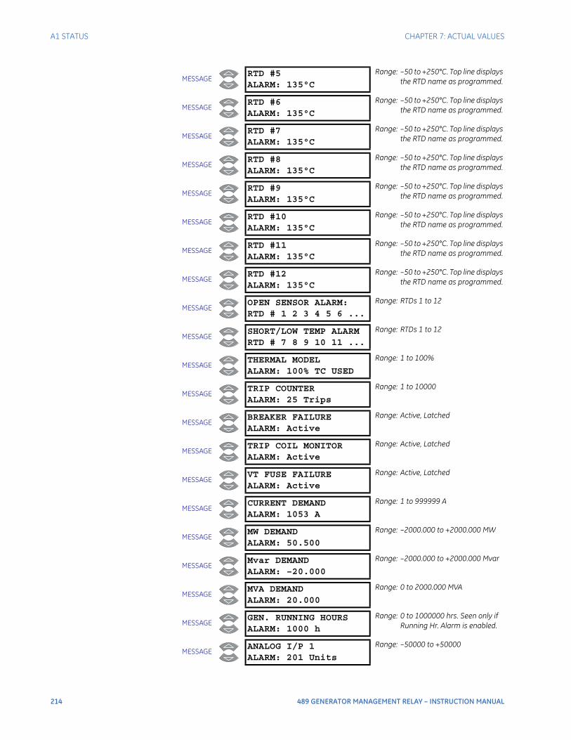
214 489 GENERATOR MANAGEMENT RELAY – INSTRUCTION MANUAL
A1 STATUS CHAPTER 7: ACTUAL VALUES
MESSAGERTD #5ALARM: 135°C
Range: –50 to +250°C. Top line displays the RTD name as programmed.
MESSAGERTD #6ALARM: 135°C
Range: –50 to +250°C. Top line displays the RTD name as programmed.
MESSAGERTD #7ALARM: 135°C
Range: –50 to +250°C. Top line displays the RTD name as programmed.
MESSAGERTD #8ALARM: 135°C
Range: –50 to +250°C. Top line displays the RTD name as programmed.
MESSAGERTD #9ALARM: 135°C
Range: –50 to +250°C. Top line displays the RTD name as programmed.
MESSAGERTD #10ALARM: 135°C
Range: –50 to +250°C. Top line displays the RTD name as programmed.
MESSAGERTD #11ALARM: 135°C
Range: –50 to +250°C. Top line displays the RTD name as programmed.
MESSAGERTD #12ALARM: 135°C
Range: –50 to +250°C. Top line displays the RTD name as programmed.
MESSAGEOPEN SENSOR ALARM:RTD # 1 2 3 4 5 6 ...
Range: RTDs 1 to 12
MESSAGESHORT/LOW TEMP ALARMRTD # 7 8 9 10 11 ...
Range: RTDs 1 to 12
MESSAGETHERMAL MODELALARM: 100% TC USED
Range: 1 to 100%
MESSAGETRIP COUNTERALARM: 25 Trips
Range: 1 to 10000
MESSAGEBREAKER FAILUREALARM: Active
Range: Active, Latched
MESSAGETRIP COIL MONITORALARM: Active
Range: Active, Latched
MESSAGEVT FUSE FAILUREALARM: Active
Range: Active, Latched
MESSAGECURRENT DEMANDALARM: 1053 A
Range: 1 to 999999 A
MESSAGEMW DEMANDALARM: 50.500
Range: –2000.000 to +2000.000 MW
MESSAGEMvar DEMANDALARM: –20.000
Range: –2000.000 to +2000.000 Mvar
MESSAGEMVA DEMANDALARM: 20.000
Range: 0 to 2000.000 MVA
MESSAGEGEN. RUNNING HOURSALARM: 1000 h
Range: 0 to 1000000 hrs. Seen only if Running Hr. Alarm is enabled.
MESSAGEANALOG I/P 1ALARM: 201 Units
Range: –50000 to +50000
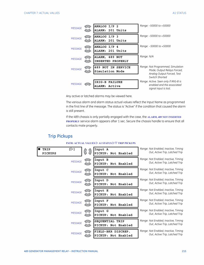
CHAPTER 7: ACTUAL VALUES A1 STATUS
489 GENERATOR MANAGEMENT RELAY – INSTRUCTION MANUAL 215
Any active or latched alarms may be viewed here.
The various alarm and alarm status actual values reflect the Input Name as programmed in the first line of the message. The status is “Active” if the condition that caused the alarm is still present.
If the 489 chassis is only partially engaged with the case, the ALARM, 489 NOT INSERTED
PROPERLY service alarm appears after 1 sec. Secure the chassis handle to ensure that all contacts mate properly.
Trip PickupsPATH: ACTUAL VALUES A1 STATUS TRIP PICKUPS
MESSAGEANALOG I/P 2ALARM: 201 Units
Range: –50000 to +50000
MESSAGEANALOG I/P 3ALARM: 201 Units
Range: –50000 to +50000
MESSAGEANALOG I/P 4ALARM: 201 Units
Range: –50000 to +50000
MESSAGEALARM, 489 NOTINSERTED PROPERLY
Range: N/A
MESSAGE489 NOT IN SERVICESimulation Mode
Range: Not Programmed, Simulation Mode, Output Relays Forced, Analog Output Forced, Test Switch Shorted
MESSAGEIRIG-B FAILUREALARM: Active
Range: Active. Seen only if IRIG-B is enabled and the associated signal input is lost.
TRIP []PICKUPS
Input APICKUP: Not Enabled
Range: Not Enabled, Inactive, Timing Out, Active Trip, Latched Trip
MESSAGEInput BPICKUP: Not Enabled
Range: Not Enabled, Inactive, Timing Out, Active Trip, Latched Trip
MESSAGEInput CPICKUP: Not Enabled
Range: Not Enabled, Inactive, Timing Out, Active Trip, Latched Trip
MESSAGEInput DPICKUP: Not Enabled
Range: Not Enabled, Inactive, Timing Out, Active Trip, Latched Trip
MESSAGEInput EPICKUP: Not Enabled
Range: Not Enabled, Inactive, Timing Out, Active Trip, Latched Trip
MESSAGEInput FPICKUP: Not Enabled
Range: Not Enabled, Inactive, Timing Out, Active Trip, Latched Trip
MESSAGEInput GPICKUP: Not Enabled
Range: Not Enabled, Inactive, Timing Out, Active Trip, Latched Trip
MESSAGESEQUENTIAL TRIPPICKUP: Not Enabled
Range: Not Enabled, Inactive, Timing Out, Active Trip, Latched Trip
MESSAGEFIELD-BKR DISCREP.PICKUP: Not Enabled
Range: Not Enabled, Inactive, Timing Out, Active Trip, Latched Trip
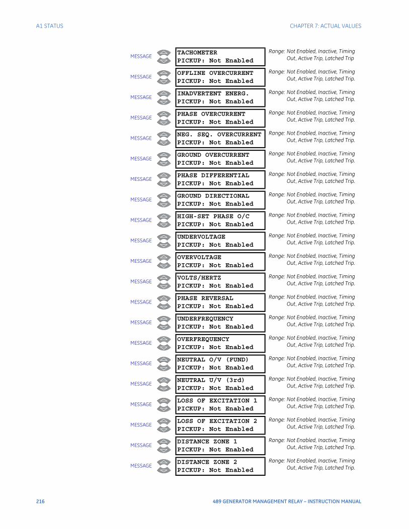
216 489 GENERATOR MANAGEMENT RELAY – INSTRUCTION MANUAL
A1 STATUS CHAPTER 7: ACTUAL VALUES
MESSAGETACHOMETERPICKUP: Not Enabled
Range: Not Enabled, Inactive, Timing Out, Active Trip, Latched Trip
MESSAGEOFFLINE OVERCURRENTPICKUP: Not Enabled
Range: Not Enabled, Inactive, Timing Out, Active Trip, Latched Trip.
MESSAGEINADVERTENT ENERG.PICKUP: Not Enabled
Range: Not Enabled, Inactive, Timing Out, Active Trip, Latched Trip.
MESSAGEPHASE OVERCURRENTPICKUP: Not Enabled
Range: Not Enabled, Inactive, Timing Out, Active Trip, Latched Trip.
MESSAGENEG. SEQ. OVERCURRENTPICKUP: Not Enabled
Range: Not Enabled, Inactive, Timing Out, Active Trip, Latched Trip.
MESSAGEGROUND OVERCURRENTPICKUP: Not Enabled
Range: Not Enabled, Inactive, Timing Out, Active Trip, Latched Trip.
MESSAGEPHASE DIFFERENTIALPICKUP: Not Enabled
Range: Not Enabled, Inactive, Timing Out, Active Trip, Latched Trip.
MESSAGEGROUND DIRECTIONALPICKUP: Not Enabled
Range: Not Enabled, Inactive, Timing Out, Active Trip, Latched Trip.
MESSAGEHIGH-SET PHASE O/CPICKUP: Not Enabled
Range: Not Enabled, Inactive, Timing Out, Active Trip, Latched Trip.
MESSAGEUNDERVOLTAGEPICKUP: Not Enabled
Range: Not Enabled, Inactive, Timing Out, Active Trip, Latched Trip.
MESSAGEOVERVOLTAGEPICKUP: Not Enabled
Range: Not Enabled, Inactive, Timing Out, Active Trip, Latched Trip.
MESSAGEVOLTS/HERTZPICKUP: Not Enabled
Range: Not Enabled, Inactive, Timing Out, Active Trip, Latched Trip.
MESSAGEPHASE REVERSALPICKUP: Not Enabled
Range: Not Enabled, Inactive, Timing Out, Active Trip, Latched Trip.
MESSAGEUNDERFREQUENCYPICKUP: Not Enabled
Range: Not Enabled, Inactive, Timing Out, Active Trip, Latched Trip.
MESSAGEOVERFREQUENCYPICKUP: Not Enabled
Range: Not Enabled, Inactive, Timing Out, Active Trip, Latched Trip.
MESSAGENEUTRAL O/V (FUND)PICKUP: Not Enabled
Range: Not Enabled, Inactive, Timing Out, Active Trip, Latched Trip.
MESSAGENEUTRAL U/V (3rd)PICKUP: Not Enabled
Range: Not Enabled, Inactive, Timing Out, Active Trip, Latched Trip.
MESSAGELOSS OF EXCITATION 1PICKUP: Not Enabled
Range: Not Enabled, Inactive, Timing Out, Active Trip, Latched Trip.
MESSAGELOSS OF EXCITATION 2PICKUP: Not Enabled
Range: Not Enabled, Inactive, Timing Out, Active Trip, Latched Trip.
MESSAGEDISTANCE ZONE 1PICKUP: Not Enabled
Range: Not Enabled, Inactive, Timing Out, Active Trip, Latched Trip.
MESSAGEDISTANCE ZONE 2PICKUP: Not Enabled
Range: Not Enabled, Inactive, Timing Out, Active Trip, Latched Trip.
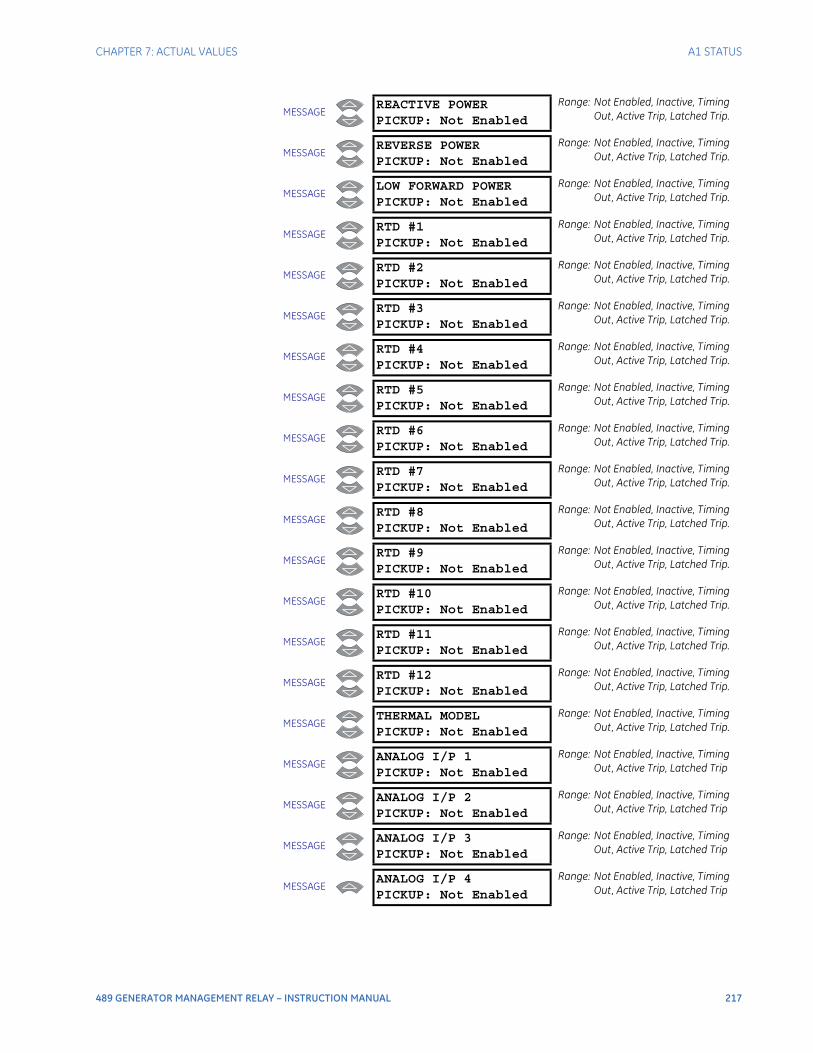
CHAPTER 7: ACTUAL VALUES A1 STATUS
489 GENERATOR MANAGEMENT RELAY – INSTRUCTION MANUAL 217
MESSAGEREACTIVE POWERPICKUP: Not Enabled
Range: Not Enabled, Inactive, Timing Out, Active Trip, Latched Trip.
MESSAGEREVERSE POWERPICKUP: Not Enabled
Range: Not Enabled, Inactive, Timing Out, Active Trip, Latched Trip.
MESSAGELOW FORWARD POWERPICKUP: Not Enabled
Range: Not Enabled, Inactive, Timing Out, Active Trip, Latched Trip.
MESSAGERTD #1PICKUP: Not Enabled
Range: Not Enabled, Inactive, Timing Out, Active Trip, Latched Trip.
MESSAGERTD #2PICKUP: Not Enabled
Range: Not Enabled, Inactive, Timing Out, Active Trip, Latched Trip.
MESSAGERTD #3PICKUP: Not Enabled
Range: Not Enabled, Inactive, Timing Out, Active Trip, Latched Trip.
MESSAGERTD #4PICKUP: Not Enabled
Range: Not Enabled, Inactive, Timing Out, Active Trip, Latched Trip.
MESSAGERTD #5PICKUP: Not Enabled
Range: Not Enabled, Inactive, Timing Out, Active Trip, Latched Trip.
MESSAGERTD #6PICKUP: Not Enabled
Range: Not Enabled, Inactive, Timing Out, Active Trip, Latched Trip.
MESSAGERTD #7PICKUP: Not Enabled
Range: Not Enabled, Inactive, Timing Out, Active Trip, Latched Trip.
MESSAGERTD #8PICKUP: Not Enabled
Range: Not Enabled, Inactive, Timing Out, Active Trip, Latched Trip.
MESSAGERTD #9PICKUP: Not Enabled
Range: Not Enabled, Inactive, Timing Out, Active Trip, Latched Trip.
MESSAGERTD #10PICKUP: Not Enabled
Range: Not Enabled, Inactive, Timing Out, Active Trip, Latched Trip.
MESSAGERTD #11PICKUP: Not Enabled
Range: Not Enabled, Inactive, Timing Out, Active Trip, Latched Trip.
MESSAGERTD #12PICKUP: Not Enabled
Range: Not Enabled, Inactive, Timing Out, Active Trip, Latched Trip.
MESSAGETHERMAL MODELPICKUP: Not Enabled
Range: Not Enabled, Inactive, Timing Out, Active Trip, Latched Trip.
MESSAGEANALOG I/P 1PICKUP: Not Enabled
Range: Not Enabled, Inactive, Timing Out, Active Trip, Latched Trip
MESSAGEANALOG I/P 2PICKUP: Not Enabled
Range: Not Enabled, Inactive, Timing Out, Active Trip, Latched Trip
MESSAGEANALOG I/P 3PICKUP: Not Enabled
Range: Not Enabled, Inactive, Timing Out, Active Trip, Latched Trip
MESSAGEANALOG I/P 4PICKUP: Not Enabled
Range: Not Enabled, Inactive, Timing Out, Active Trip, Latched Trip
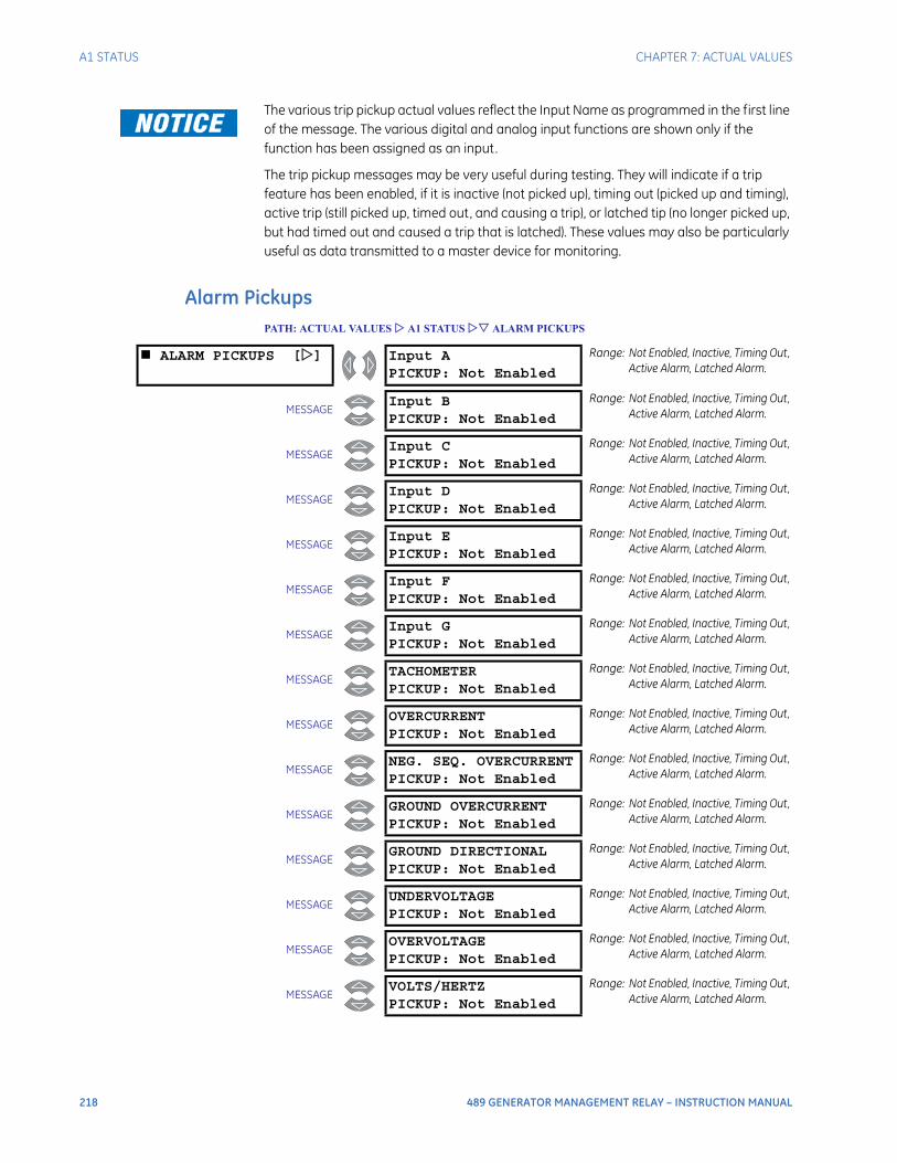
218 489 GENERATOR MANAGEMENT RELAY – INSTRUCTION MANUAL
A1 STATUS CHAPTER 7: ACTUAL VALUES
The various trip pickup actual values reflect the Input Name as programmed in the first line of the message. The various digital and analog input functions are shown only if the function has been assigned as an input.
The trip pickup messages may be very useful during testing. They will indicate if a trip feature has been enabled, if it is inactive (not picked up), timing out (picked up and timing), active trip (still picked up, timed out, and causing a trip), or latched tip (no longer picked up, but had timed out and caused a trip that is latched). These values may also be particularly useful as data transmitted to a master device for monitoring.
Alarm PickupsPATH: ACTUAL VALUES A1 STATUS ALARM PICKUPS
ALARM PICKUPS [] Input APICKUP: Not Enabled
Range: Not Enabled, Inactive, Timing Out, Active Alarm, Latched Alarm.
MESSAGEInput BPICKUP: Not Enabled
Range: Not Enabled, Inactive, Timing Out, Active Alarm, Latched Alarm.
MESSAGEInput CPICKUP: Not Enabled
Range: Not Enabled, Inactive, Timing Out, Active Alarm, Latched Alarm.
MESSAGEInput DPICKUP: Not Enabled
Range: Not Enabled, Inactive, Timing Out, Active Alarm, Latched Alarm.
MESSAGEInput EPICKUP: Not Enabled
Range: Not Enabled, Inactive, Timing Out, Active Alarm, Latched Alarm.
MESSAGEInput FPICKUP: Not Enabled
Range: Not Enabled, Inactive, Timing Out, Active Alarm, Latched Alarm.
MESSAGEInput GPICKUP: Not Enabled
Range: Not Enabled, Inactive, Timing Out, Active Alarm, Latched Alarm.
MESSAGETACHOMETERPICKUP: Not Enabled
Range: Not Enabled, Inactive, Timing Out, Active Alarm, Latched Alarm.
MESSAGEOVERCURRENTPICKUP: Not Enabled
Range: Not Enabled, Inactive, Timing Out, Active Alarm, Latched Alarm.
MESSAGENEG. SEQ. OVERCURRENTPICKUP: Not Enabled
Range: Not Enabled, Inactive, Timing Out, Active Alarm, Latched Alarm.
MESSAGEGROUND OVERCURRENTPICKUP: Not Enabled
Range: Not Enabled, Inactive, Timing Out, Active Alarm, Latched Alarm.
MESSAGEGROUND DIRECTIONALPICKUP: Not Enabled
Range: Not Enabled, Inactive, Timing Out, Active Alarm, Latched Alarm.
MESSAGEUNDERVOLTAGEPICKUP: Not Enabled
Range: Not Enabled, Inactive, Timing Out, Active Alarm, Latched Alarm.
MESSAGEOVERVOLTAGEPICKUP: Not Enabled
Range: Not Enabled, Inactive, Timing Out, Active Alarm, Latched Alarm.
MESSAGEVOLTS/HERTZPICKUP: Not Enabled
Range: Not Enabled, Inactive, Timing Out, Active Alarm, Latched Alarm.
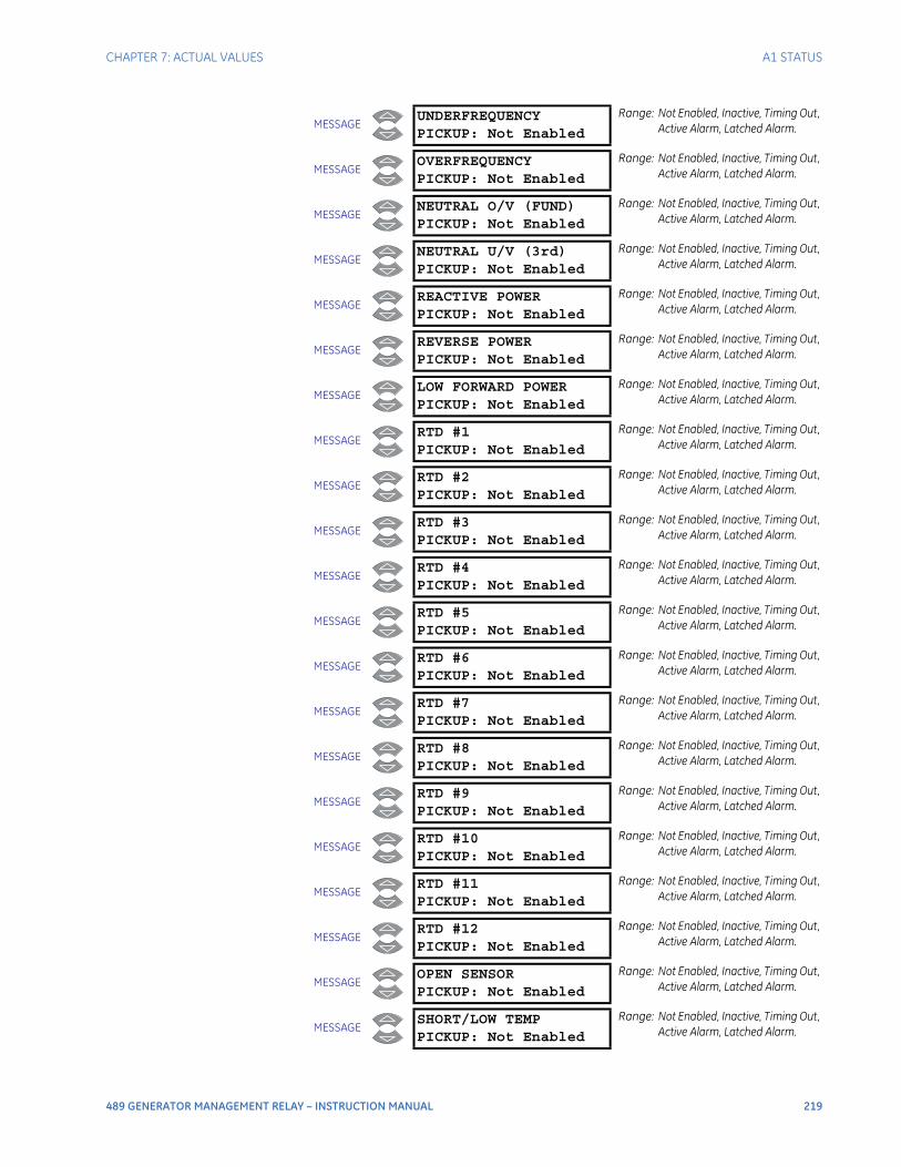
CHAPTER 7: ACTUAL VALUES A1 STATUS
489 GENERATOR MANAGEMENT RELAY – INSTRUCTION MANUAL 219
MESSAGEUNDERFREQUENCYPICKUP: Not Enabled
Range: Not Enabled, Inactive, Timing Out, Active Alarm, Latched Alarm.
MESSAGEOVERFREQUENCYPICKUP: Not Enabled
Range: Not Enabled, Inactive, Timing Out, Active Alarm, Latched Alarm.
MESSAGENEUTRAL O/V (FUND)PICKUP: Not Enabled
Range: Not Enabled, Inactive, Timing Out, Active Alarm, Latched Alarm.
MESSAGENEUTRAL U/V (3rd)PICKUP: Not Enabled
Range: Not Enabled, Inactive, Timing Out, Active Alarm, Latched Alarm.
MESSAGEREACTIVE POWERPICKUP: Not Enabled
Range: Not Enabled, Inactive, Timing Out, Active Alarm, Latched Alarm.
MESSAGEREVERSE POWERPICKUP: Not Enabled
Range: Not Enabled, Inactive, Timing Out, Active Alarm, Latched Alarm.
MESSAGELOW FORWARD POWERPICKUP: Not Enabled
Range: Not Enabled, Inactive, Timing Out, Active Alarm, Latched Alarm.
MESSAGERTD #1PICKUP: Not Enabled
Range: Not Enabled, Inactive, Timing Out, Active Alarm, Latched Alarm.
MESSAGERTD #2PICKUP: Not Enabled
Range: Not Enabled, Inactive, Timing Out, Active Alarm, Latched Alarm.
MESSAGERTD #3PICKUP: Not Enabled
Range: Not Enabled, Inactive, Timing Out, Active Alarm, Latched Alarm.
MESSAGERTD #4PICKUP: Not Enabled
Range: Not Enabled, Inactive, Timing Out, Active Alarm, Latched Alarm.
MESSAGERTD #5PICKUP: Not Enabled
Range: Not Enabled, Inactive, Timing Out, Active Alarm, Latched Alarm.
MESSAGERTD #6PICKUP: Not Enabled
Range: Not Enabled, Inactive, Timing Out, Active Alarm, Latched Alarm.
MESSAGERTD #7PICKUP: Not Enabled
Range: Not Enabled, Inactive, Timing Out, Active Alarm, Latched Alarm.
MESSAGERTD #8PICKUP: Not Enabled
Range: Not Enabled, Inactive, Timing Out, Active Alarm, Latched Alarm.
MESSAGERTD #9PICKUP: Not Enabled
Range: Not Enabled, Inactive, Timing Out, Active Alarm, Latched Alarm.
MESSAGERTD #10PICKUP: Not Enabled
Range: Not Enabled, Inactive, Timing Out, Active Alarm, Latched Alarm.
MESSAGERTD #11PICKUP: Not Enabled
Range: Not Enabled, Inactive, Timing Out, Active Alarm, Latched Alarm.
MESSAGERTD #12PICKUP: Not Enabled
Range: Not Enabled, Inactive, Timing Out, Active Alarm, Latched Alarm.
MESSAGEOPEN SENSORPICKUP: Not Enabled
Range: Not Enabled, Inactive, Timing Out, Active Alarm, Latched Alarm.
MESSAGESHORT/LOW TEMPPICKUP: Not Enabled
Range: Not Enabled, Inactive, Timing Out, Active Alarm, Latched Alarm.
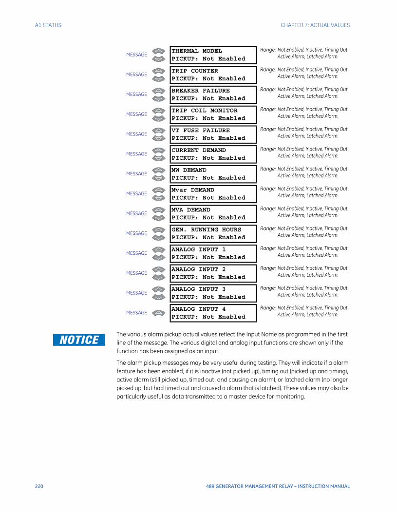
220 489 GENERATOR MANAGEMENT RELAY – INSTRUCTION MANUAL
A1 STATUS CHAPTER 7: ACTUAL VALUES
The various alarm pickup actual values reflect the Input Name as programmed in the first line of the message. The various digital and analog input functions are shown only if the function has been assigned as an input.
The alarm pickup messages may be very useful during testing. They will indicate if a alarm feature has been enabled, if it is inactive (not picked up), timing out (picked up and timing), active alarm (still picked up, timed out, and causing an alarm), or latched alarm (no longer picked up, but had timed out and caused a alarm that is latched). These values may also be particularly useful as data transmitted to a master device for monitoring.
MESSAGETHERMAL MODELPICKUP: Not Enabled
Range: Not Enabled, Inactive, Timing Out, Active Alarm, Latched Alarm.
MESSAGETRIP COUNTERPICKUP: Not Enabled
Range: Not Enabled, Inactive, Timing Out, Active Alarm, Latched Alarm.
MESSAGEBREAKER FAILUREPICKUP: Not Enabled
Range: Not Enabled, Inactive, Timing Out, Active Alarm, Latched Alarm.
MESSAGETRIP COIL MONITORPICKUP: Not Enabled
Range: Not Enabled, Inactive, Timing Out, Active Alarm, Latched Alarm.
MESSAGEVT FUSE FAILUREPICKUP: Not Enabled
Range: Not Enabled, Inactive, Timing Out, Active Alarm, Latched Alarm.
MESSAGECURRENT DEMANDPICKUP: Not Enabled
Range: Not Enabled, Inactive, Timing Out, Active Alarm, Latched Alarm.
MESSAGEMW DEMANDPICKUP: Not Enabled
Range: Not Enabled, Inactive, Timing Out, Active Alarm, Latched Alarm.
MESSAGEMvar DEMANDPICKUP: Not Enabled
Range: Not Enabled, Inactive, Timing Out, Active Alarm, Latched Alarm.
MESSAGEMVA DEMANDPICKUP: Not Enabled
Range: Not Enabled, Inactive, Timing Out, Active Alarm, Latched Alarm.
MESSAGEGEN. RUNNING HOURSPICKUP: Not Enabled
Range: Not Enabled, Inactive, Timing Out, Active Alarm, Latched Alarm.
MESSAGEANALOG INPUT 1PICKUP: Not Enabled
Range: Not Enabled, Inactive, Timing Out, Active Alarm, Latched Alarm.
MESSAGEANALOG INPUT 2PICKUP: Not Enabled
Range: Not Enabled, Inactive, Timing Out, Active Alarm, Latched Alarm.
MESSAGEANALOG INPUT 3PICKUP: Not Enabled
Range: Not Enabled, Inactive, Timing Out, Active Alarm, Latched Alarm.
MESSAGEANALOG INPUT 4PICKUP: Not Enabled
Range: Not Enabled, Inactive, Timing Out, Active Alarm, Latched Alarm.
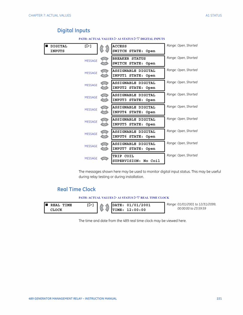
CHAPTER 7: ACTUAL VALUES A1 STATUS
489 GENERATOR MANAGEMENT RELAY – INSTRUCTION MANUAL 221
Digital InputsPATH: ACTUAL VALUES A1 STATUS DIGITAL INPUTS
The messages shown here may be used to monitor digital input status. This may be useful during relay testing or during installation.
Real Time ClockPATH: ACTUAL VALUES A1 STATUS REAL TIME CLOCK
The time and date from the 489 real time clock may be viewed here.
DIGITAL []INPUTS
ACCESSSWITCH STATE: Open
Range: Open, Shorted
MESSAGEBREAKER STATUSSWITCH STATE: Open
Range: Open, Shorted
MESSAGEASSIGNABLE DIGITALINPUT1 STATE: Open
Range: Open, Shorted
MESSAGEASSIGNABLE DIGITALINPUT2 STATE: Open
Range: Open, Shorted
MESSAGEASSIGNABLE DIGITALINPUT3 STATE: Open
Range: Open, Shorted
MESSAGEASSIGNABLE DIGITALINPUT4 STATE: Open
Range: Open, Shorted
MESSAGEASSIGNABLE DIGITALINPUT5 STATE: Open
Range: Open, Shorted
MESSAGEASSIGNABLE DIGITALINPUT6 STATE: Open
Range: Open, Shorted
MESSAGEASSIGNABLE DIGITALINPUT7 STATE: Open
Range: Open, Shorted
MESSAGETRIP COILSUPERVISION: No Coil
Range: Open, Shorted
REAL TIME []CLOCK
DATE: 01/01/2001TIME: 12:00:00
Range: 01/01/2001 to 12/31/2099, 00:00:00 to 23:59:59
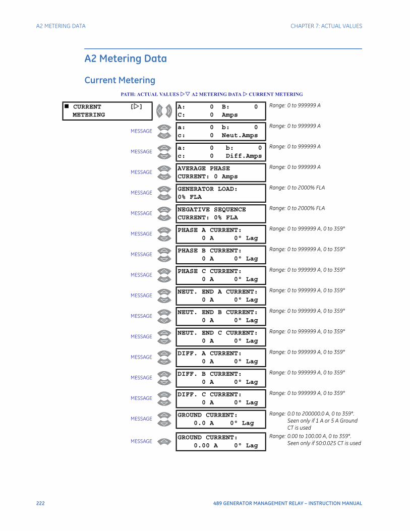
222 489 GENERATOR MANAGEMENT RELAY – INSTRUCTION MANUAL
A2 METERING DATA CHAPTER 7: ACTUAL VALUES
A2 Metering Data
Current MeteringPATH: ACTUAL VALUES A2 METERING DATA CURRENT METERING
CURRENT []METERING
A: 0 B: 0C: 0 Amps
Range: 0 to 999999 A
MESSAGEa: 0 b: 0c: 0 Neut.Amps
Range: 0 to 999999 A
MESSAGEa: 0 b: 0c: 0 Diff.Amps
Range: 0 to 999999 A
MESSAGEAVERAGE PHASECURRENT: 0 Amps
Range: 0 to 999999 A
MESSAGEGENERATOR LOAD:0% FLA
Range: 0 to 2000% FLA
MESSAGENEGATIVE SEQUENCECURRENT: 0% FLA
Range: 0 to 2000% FLA
MESSAGEPHASE A CURRENT:
0 A 0° Lag
Range: 0 to 999999 A, 0 to 359°
MESSAGEPHASE B CURRENT:
0 A 0° Lag
Range: 0 to 999999 A, 0 to 359°
MESSAGEPHASE C CURRENT:
0 A 0° Lag
Range: 0 to 999999 A, 0 to 359°
MESSAGENEUT. END A CURRENT:
0 A 0° Lag
Range: 0 to 999999 A, 0 to 359°
MESSAGENEUT. END B CURRENT:
0 A 0° Lag
Range: 0 to 999999 A, 0 to 359°
MESSAGENEUT. END C CURRENT:
0 A 0° Lag
Range: 0 to 999999 A, 0 to 359°
MESSAGEDIFF. A CURRENT:
0 A 0° Lag
Range: 0 to 999999 A, 0 to 359°
MESSAGEDIFF. B CURRENT:
0 A 0° Lag
Range: 0 to 999999 A, 0 to 359°
MESSAGEDIFF. C CURRENT:
0 A 0° Lag
Range: 0 to 999999 A, 0 to 359°
MESSAGEGROUND CURRENT:
0.0 A 0° Lag
Range: 0.0 to 200000.0 A, 0 to 359°. Seen only if 1 A or 5 A Ground CT is used
MESSAGEGROUND CURRENT:
0.00 A 0° Lag
Range: 0.00 to 100.00 A, 0 to 359°. Seen only if 50:0.025 CT is used
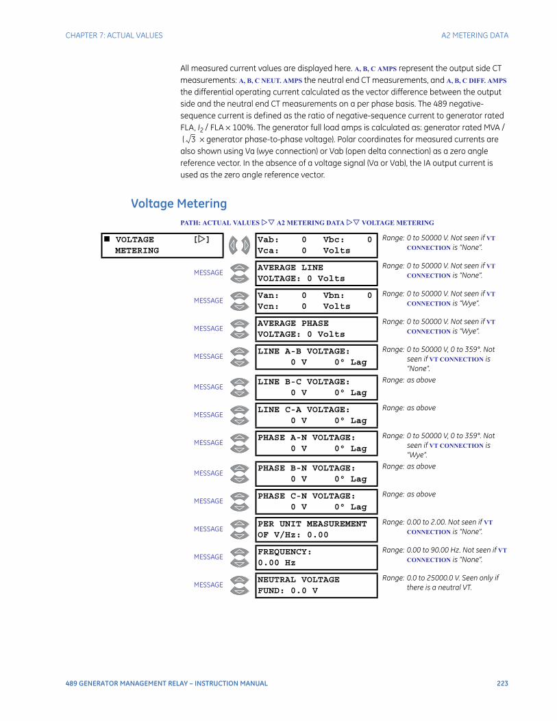
CHAPTER 7: ACTUAL VALUES A2 METERING DATA
489 GENERATOR MANAGEMENT RELAY – INSTRUCTION MANUAL 223
All measured current values are displayed here. A, B, C AMPS represent the output side CT measurements: A, B, C NEUT. AMPS the neutral end CT measurements, and A, B, C DIFF. AMPS the differential operating current calculated as the vector difference between the output side and the neutral end CT measurements on a per phase basis. The 489 negative-sequence current is defined as the ratio of negative-sequence current to generator rated FLA, I2 / FLA × 100%. The generator full load amps is calculated as: generator rated MVA /( × generator phase-to-phase voltage). Polar coordinates for measured currents are
also shown using Va (wye connection) or Vab (open delta connection) as a zero angle reference vector. In the absence of a voltage signal (Va or Vab), the IA output current is used as the zero angle reference vector.
Voltage MeteringPATH: ACTUAL VALUES A2 METERING DATA VOLTAGE METERING
3
VOLTAGE []METERING
Vab: 0 Vbc: 0Vca: 0 Volts
Range: 0 to 50000 V. Not seen if VT
CONNECTION is “None”.
MESSAGEAVERAGE LINEVOLTAGE: 0 Volts
Range: 0 to 50000 V. Not seen if VT
CONNECTION is “None”.
MESSAGEVan: 0 Vbn: 0Vcn: 0 Volts
Range: 0 to 50000 V. Not seen if VT
CONNECTION is “Wye”.
MESSAGEAVERAGE PHASEVOLTAGE: 0 Volts
Range: 0 to 50000 V. Not seen if VT
CONNECTION is “Wye”.
MESSAGELINE A-B VOLTAGE:
0 V 0° Lag
Range: 0 to 50000 V, 0 to 359°. Not seen if VT CONNECTION is “None”.
MESSAGELINE B-C VOLTAGE:
0 V 0° Lag
Range: as above
MESSAGELINE C-A VOLTAGE:
0 V 0° Lag
Range: as above
MESSAGEPHASE A-N VOLTAGE:
0 V 0° Lag
Range: 0 to 50000 V, 0 to 359°. Not seen if VT CONNECTION is “Wye”.
MESSAGEPHASE B-N VOLTAGE:
0 V 0° Lag
Range: as above
MESSAGEPHASE C-N VOLTAGE:
0 V 0° Lag
Range: as above
MESSAGEPER UNIT MEASUREMENTOF V/Hz: 0.00
Range: 0.00 to 2.00. Not seen if VT
CONNECTION is “None”.
MESSAGEFREQUENCY:0.00 Hz
Range: 0.00 to 90.00 Hz. Not seen if VT
CONNECTION is “None”.
MESSAGENEUTRAL VOLTAGEFUND: 0.0 V
Range: 0.0 to 25000.0 V. Seen only if there is a neutral VT.
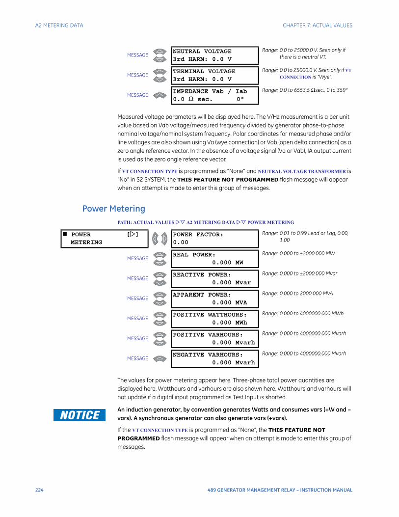
224 489 GENERATOR MANAGEMENT RELAY – INSTRUCTION MANUAL
A2 METERING DATA CHAPTER 7: ACTUAL VALUES
Measured voltage parameters will be displayed here. The V/Hz measurement is a per unit value based on Vab voltage/measured frequency divided by generator phase-to-phase nominal voltage/nominal system frequency. Polar coordinates for measured phase and/or line voltages are also shown using Va (wye connection) or Vab (open delta connection) as a zero angle reference vector. In the absence of a voltage signal (Va or Vab), IA output current is used as the zero angle reference vector.
If VT CONNECTION TYPE is programmed as “None” and NEUTRAL VOLTAGE TRANSFORMER is “No” in S2 SYSTEM, the THIS FEATURE NOT PROGRAMMED flash message will appear when an attempt is made to enter this group of messages.
Power MeteringPATH: ACTUAL VALUES A2 METERING DATA POWER METERING
The values for power metering appear here. Three-phase total power quantities are displayed here. Watthours and varhours are also shown here. Watthours and varhours will not update if a digital input programmed as Test Input is shorted.
An induction generator, by convention generates Watts and consumes vars (+W and –vars). A synchronous generator can also generate vars (+vars).
If the VT CONNECTION TYPE is programmed as “None”, the THIS FEATURE NOT PROGRAMMED flash message will appear when an attempt is made to enter this group of messages.
MESSAGENEUTRAL VOLTAGE3rd HARM: 0.0 V
Range: 0.0 to 25000.0 V. Seen only if there is a neutral VT.
MESSAGETERMINAL VOLTAGE3rd HARM: 0.0 V
Range: 0.0 to 25000.0 V. Seen only if VT
CONNECTION is “Wye”.
MESSAGEIMPEDANCE Vab / Iab0.0 Ω sec. 0°
Range: 0.0 to 6553.5 Ωsec., 0 to 359°
POWER []METERING
POWER FACTOR:0.00
Range: 0.01 to 0.99 Lead or Lag, 0.00, 1.00
MESSAGEREAL POWER:
0.000 MW
Range: 0.000 to ±2000.000 MW
MESSAGEREACTIVE POWER:
0.000 Mvar
Range: 0.000 to ±2000.000 Mvar
MESSAGEAPPARENT POWER:
0.000 MVA
Range: 0.000 to 2000.000 MVA
MESSAGEPOSITIVE WATTHOURS:
0.000 MWh
Range: 0.000 to 4000000.000 MWh
MESSAGEPOSITIVE VARHOURS:
0.000 Mvarh
Range: 0.000 to 4000000.000 Mvarh
MESSAGENEGATIVE VARHOURS:
0.000 Mvarh
Range: 0.000 to 4000000.000 Mvarh
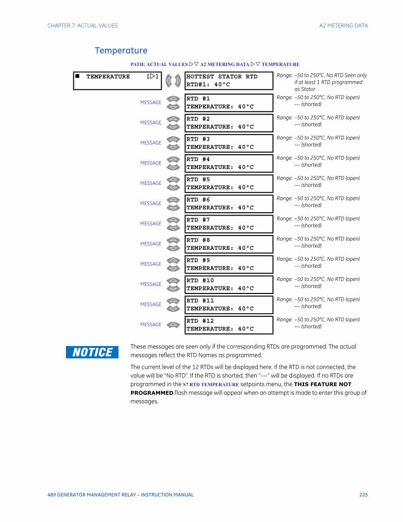
CHAPTER 7: ACTUAL VALUES A2 METERING DATA
489 GENERATOR MANAGEMENT RELAY – INSTRUCTION MANUAL 225
TemperaturePATH: ACTUAL VALUES A2 METERING DATA TEMPERATURE
These messages are seen only if the corresponding RTDs are programmed. The actual messages reflect the RTD Names as programmed.
The current level of the 12 RTDs will be displayed here. If the RTD is not connected, the value will be “No RTD”. If the RTD is shorted, then “---” will be displayed. If no RTDs are programmed in the S7 RTD TEMPERATURE setpoints menu, the THIS FEATURE NOT PROGRAMMED flash message will appear when an attempt is made to enter this group of messages.
TEMPERATURE [] HOTTEST STATOR RTDRTD#1: 40°C
Range: –50 to 250°C, No RTD Seen only if at least 1 RTD programmed as Stator
MESSAGERTD #1TEMPERATURE: 40°C
Range: –50 to 250°C, No RTD (open)--- (shorted)
MESSAGERTD #2TEMPERATURE: 40°C
Range: –50 to 250°C, No RTD (open)--- (shorted)
MESSAGERTD #3TEMPERATURE: 40°C
Range: –50 to 250°C, No RTD (open)--- (shorted)
MESSAGERTD #4TEMPERATURE: 40°C
Range: –50 to 250°C, No RTD (open)--- (shorted)
MESSAGERTD #5TEMPERATURE: 40°C
Range: –50 to 250°C, No RTD (open)--- (shorted)
MESSAGERTD #6TEMPERATURE: 40°C
Range: –50 to 250°C, No RTD (open)--- (shorted)
MESSAGERTD #7TEMPERATURE: 40°C
Range: –50 to 250°C, No RTD (open)--- (shorted)
MESSAGERTD #8TEMPERATURE: 40°C
Range: –50 to 250°C, No RTD (open)--- (shorted)
MESSAGERTD #9TEMPERATURE: 40°C
Range: –50 to 250°C, No RTD (open)--- (shorted)
MESSAGERTD #10TEMPERATURE: 40°C
Range: –50 to 250°C, No RTD (open)--- (shorted)
MESSAGERTD #11TEMPERATURE: 40°C
Range: –50 to 250°C, No RTD (open)--- (shorted)
MESSAGERTD #12TEMPERATURE: 40°C
Range: –50 to 250°C, No RTD (open)--- (shorted)
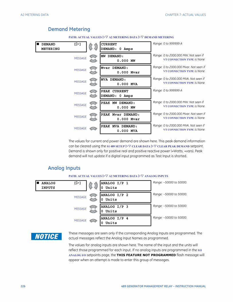
226 489 GENERATOR MANAGEMENT RELAY – INSTRUCTION MANUAL
A2 METERING DATA CHAPTER 7: ACTUAL VALUES
Demand MeteringPATH: ACTUAL VALUES A2 METERING DATA DEMAND METERING
The values for current and power demand are shown here. This peak demand information can be cleared using the S1 489 SETUP CLEAR DATA CLEAR PEAK DEMAND setpoint. Demand is shown only for positive real and positive reactive power (+Watts, +vars). Peak demand will not update if a digital input programmed as Test Input is shorted.
Analog InputsPATH: ACTUAL VALUES A2 METERING DATA ANALOG INPUTS
These messages are seen only if the corresponding Analog Inputs are programmed. The actual messages reflect the Analog Input Names as programmed.
The values for analog inputs are shown here. The name of the input and the units will reflect those programmed for each input. If no analog inputs are programmed in the S11
ANALOG I/O setpoints page, the THIS FEATURE NOT PROGRAMMED flash message will appear when an attempt is made to enter this group of messages.
DEMAND []METERING
CURRENTDEMAND: 0 Amps
Range: 0 to 999999 A
MESSAGEMW DEMAND:
0.000 MW
Range: 0 to 2000.000 MW. Not seen if VT CONNECTION TYPE is None
MESSAGEMvar DEMAND:
0.000 Mvar
Range: 0 to 2000.000 Mvar. Not seen if VT CONNECTION TYPE is None
MESSAGEMVA DEMAND:
0.000 MVA
Range: 0 to 2000.000 MVA. Not seen if VT CONNECTION TYPE is None
MESSAGEPEAK CURRENTDEMAND: 0 Amps
Range: 0 to 999999 A
MESSAGEPEAK MW DEMAND:
0.000 MW
Range: 0 to 2000.000 MW. Not seen if VT CONNECTION TYPE is None
MESSAGEPEAK Mvar DEMAND:
0.000 Mvar
Range: 0 to 2000.000 Mvar. Not seen if VT CONNECTION TYPE is None
MESSAGEPEAK MVA DEMAND:
0.000 MVA
Range: 0 to 2000.000 MVA. Not seen if VT CONNECTION TYPE is None
ANALOG []INPUTS
ANALOG I/P 10 Units
Range: –50000 to 50000.
MESSAGEANALOG I/P 20 Units
Range: –50000 to 50000.
MESSAGEANALOG I/P 30 Units
Range: –50000 to 50000.
MESSAGEANALOG I/P 40 Units
Range: –50000 to 50000.

CHAPTER 7: ACTUAL VALUES A2 METERING DATA
489 GENERATOR MANAGEMENT RELAY – INSTRUCTION MANUAL 227
SpeedPATH: ACTUAL VALUES A2 METERING DATA SPEED
If the Tachometer function is assigned to one of the digital inputs, its speed be viewed here. If no digital input is configured for tachometer, the THIS FEATURE NOT PROGRAMMED flash message will appear when an attempt is made to enter this group of messages.
SPEED [] TACHOMETER: 0 RPM Range: 0 to 7200 RPM
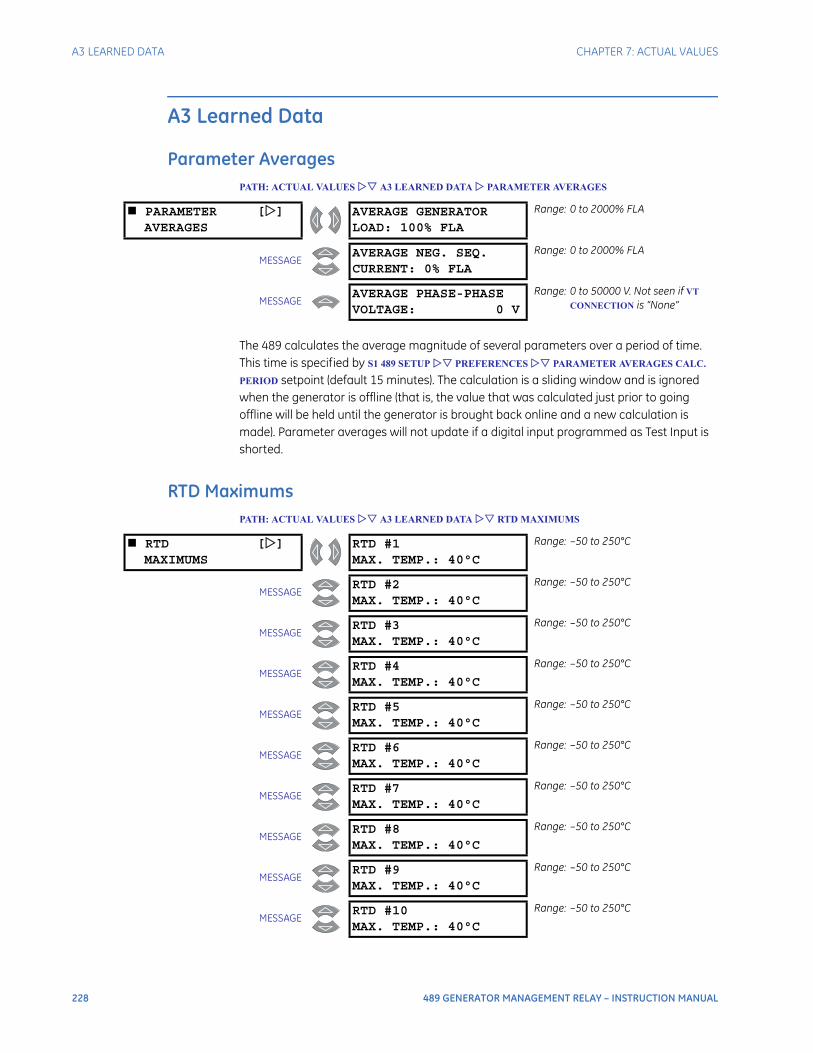
228 489 GENERATOR MANAGEMENT RELAY – INSTRUCTION MANUAL
A3 LEARNED DATA CHAPTER 7: ACTUAL VALUES
A3 Learned Data
Parameter AveragesPATH: ACTUAL VALUES A3 LEARNED DATA PARAMETER AVERAGES
The 489 calculates the average magnitude of several parameters over a period of time. This time is specified by S1 489 SETUP PREFERENCES PARAMETER AVERAGES CALC.
PERIOD setpoint (default 15 minutes). The calculation is a sliding window and is ignored when the generator is offline (that is, the value that was calculated just prior to going offline will be held until the generator is brought back online and a new calculation is made). Parameter averages will not update if a digital input programmed as Test Input is shorted.
RTD MaximumsPATH: ACTUAL VALUES A3 LEARNED DATA RTD MAXIMUMS
PARAMETER []AVERAGES
AVERAGE GENERATORLOAD: 100% FLA
Range: 0 to 2000% FLA
MESSAGEAVERAGE NEG. SEQ.CURRENT: 0% FLA
Range: 0 to 2000% FLA
MESSAGEAVERAGE PHASE-PHASEVOLTAGE: 0 V
Range: 0 to 50000 V. Not seen if VT
CONNECTION is “None”
RTD []MAXIMUMS
RTD #1MAX. TEMP.: 40°C
Range: –50 to 250°C
MESSAGERTD #2MAX. TEMP.: 40°C
Range: –50 to 250°C
MESSAGERTD #3MAX. TEMP.: 40°C
Range: –50 to 250°C
MESSAGERTD #4MAX. TEMP.: 40°C
Range: –50 to 250°C
MESSAGERTD #5MAX. TEMP.: 40°C
Range: –50 to 250°C
MESSAGERTD #6MAX. TEMP.: 40°C
Range: –50 to 250°C
MESSAGERTD #7MAX. TEMP.: 40°C
Range: –50 to 250°C
MESSAGERTD #8MAX. TEMP.: 40°C
Range: –50 to 250°C
MESSAGERTD #9MAX. TEMP.: 40°C
Range: –50 to 250°C
MESSAGERTD #10MAX. TEMP.: 40°C
Range: –50 to 250°C
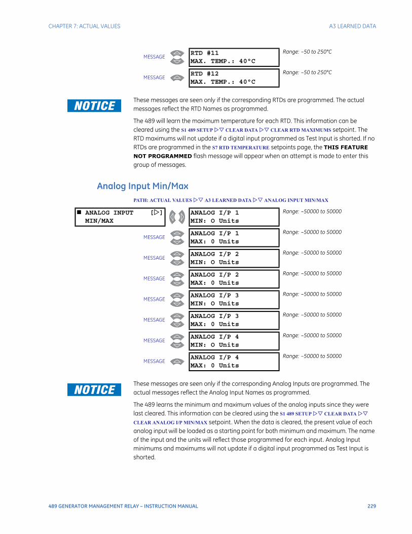
CHAPTER 7: ACTUAL VALUES A3 LEARNED DATA
489 GENERATOR MANAGEMENT RELAY – INSTRUCTION MANUAL 229
These messages are seen only if the corresponding RTDs are programmed. The actual messages reflect the RTD Names as programmed.
The 489 will learn the maximum temperature for each RTD. This information can be cleared using the S1 489 SETUP CLEAR DATA CLEAR RTD MAXIMUMS setpoint. The RTD maximums will not update if a digital input programmed as Test Input is shorted. If no RTDs are programmed in the S7 RTD TEMPERATURE setpoints page, the THIS FEATURE NOT PROGRAMMED flash message will appear when an attempt is made to enter this group of messages.
Analog Input Min/MaxPATH: ACTUAL VALUES A3 LEARNED DATA ANALOG INPUT MIN/MAX
These messages are seen only if the corresponding Analog Inputs are programmed. The actual messages reflect the Analog Input Names as programmed.
The 489 learns the minimum and maximum values of the analog inputs since they were last cleared. This information can be cleared using the S1 489 SETUP CLEAR DATA
CLEAR ANALOG I/P MIN/MAX setpoint. When the data is cleared, the present value of each analog input will be loaded as a starting point for both minimum and maximum. The name of the input and the units will reflect those programmed for each input. Analog Input minimums and maximums will not update if a digital input programmed as Test Input is shorted.
MESSAGERTD #11MAX. TEMP.: 40°C
Range: –50 to 250°C
MESSAGERTD #12MAX. TEMP.: 40°C
Range: –50 to 250°C
ANALOG INPUT []MIN/MAX
ANALOG I/P 1MIN: O Units
Range: –50000 to 50000
MESSAGEANALOG I/P 1MAX: 0 Units
Range: –50000 to 50000
MESSAGEANALOG I/P 2MIN: O Units
Range: –50000 to 50000
MESSAGEANALOG I/P 2MAX: 0 Units
Range: –50000 to 50000
MESSAGEANALOG I/P 3MIN: O Units
Range: –50000 to 50000
MESSAGEANALOG I/P 3MAX: 0 Units
Range: –50000 to 50000
MESSAGEANALOG I/P 4MIN: O Units
Range: –50000 to 50000
MESSAGEANALOG I/P 4MAX: 0 Units
Range: –50000 to 50000

230 489 GENERATOR MANAGEMENT RELAY – INSTRUCTION MANUAL
A4 MAINTENANCE CHAPTER 7: ACTUAL VALUES
If no Analog Inputs are programmed in the S11 ANALOG I/O setpoints menu, the THIS FEATURE NOT PROGRAMMED flash message will appear when an attempt is made to enter this group of messages.
A4 Maintenance
Trip CountersPATH: ACTUAL VALUES A4 MAINTENANCE TRIP COUNTERS
TRIP []
TOTAL NUMBER OFTRIPS: 0
Range: 0 to 50000
MESSAGEDIGITAL INPUTTRIPS: 0
Range: 0 to 50000. Caused by the General Input Trip feature
MESSAGESEQUENTIALTRIPS: 0
Range: 0 to 50000
MESSAGEFIELD-BKR DISCREP.TRIPS: 0
Range: 0 to 50000
MESSAGETACHOMETERTRIPS: 0
Range: 0 to 50000
MESSAGEOFFLINE OVERCURRENTTRIPS: 0
Range: 0 to 50000
MESSAGEPHASE OVERCURRENTTRIPS: 0
Range: 0 to 50000
MESSAGENEG. SEQ. OVERCURRENTTRIPS: 0
Range: 0 to 50000
MESSAGEGROUND OVERCURRENTTRIPS: 0
Range: 0 to 50000
MESSAGEPHASE DIFFERENTIALTRIPS: 0
Range: 0 to 50000
MESSAGEGROUND DIRECTIONALTRIPS: 0
Range: 0 to 50000
MESSAGEHIGH-SET PHASE O/CTRIPS: 0
Range: 0 to 50000
MESSAGEUNDERVOLTAGETRIPS: 0
Range: 0 to 50000
MESSAGEOVERVOLTAGETRIPS: 0
Range: 0 to 50000
MESSAGEVOLTS/HERTZTRIPS: 0
Range: 0 to 50000
MESSAGEPHASE REVERSALTRIPS: 0
Range: 0 to 50000
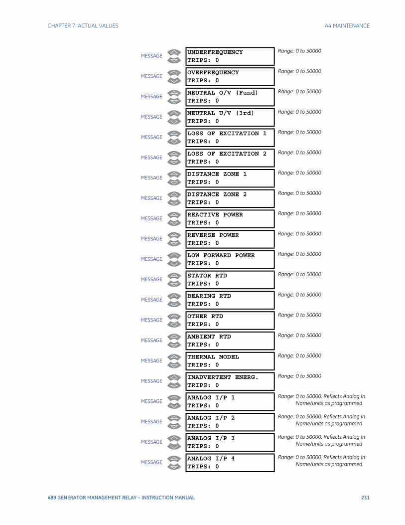
CHAPTER 7: ACTUAL VALUES A4 MAINTENANCE
489 GENERATOR MANAGEMENT RELAY – INSTRUCTION MANUAL 231
MESSAGEUNDERFREQUENCYTRIPS: 0
Range: 0 to 50000
MESSAGEOVERFREQUENCYTRIPS: 0
Range: 0 to 50000
MESSAGENEUTRAL O/V (Fund)TRIPS: 0
Range: 0 to 50000
MESSAGENEUTRAL U/V (3rd)TRIPS: 0
Range: 0 to 50000
MESSAGELOSS OF EXCITATION 1TRIPS: 0
Range: 0 to 50000
MESSAGELOSS OF EXCITATION 2TRIPS: 0
Range: 0 to 50000
MESSAGEDISTANCE ZONE 1TRIPS: 0
Range: 0 to 50000
MESSAGEDISTANCE ZONE 2TRIPS: 0
Range: 0 to 50000
MESSAGEREACTIVE POWERTRIPS: 0
Range: 0 to 50000
MESSAGEREVERSE POWERTRIPS: 0
Range: 0 to 50000
MESSAGELOW FORWARD POWERTRIPS: 0
Range: 0 to 50000
MESSAGESTATOR RTDTRIPS: 0
Range: 0 to 50000
MESSAGEBEARING RTDTRIPS: 0
Range: 0 to 50000
MESSAGEOTHER RTDTRIPS: 0
Range: 0 to 50000
MESSAGEAMBIENT RTDTRIPS: 0
Range: 0 to 50000
MESSAGETHERMAL MODELTRIPS: 0
Range: 0 to 50000
MESSAGEINADVERTENT ENERG.TRIPS: 0
Range: 0 to 50000
MESSAGEANALOG I/P 1TRIPS: 0
Range: 0 to 50000. Reflects Analog In Name/units as programmed
MESSAGEANALOG I/P 2TRIPS: 0
Range: 0 to 50000. Reflects Analog In Name/units as programmed
MESSAGEANALOG I/P 3TRIPS: 0
Range: 0 to 50000. Reflects Analog In Name/units as programmed
MESSAGEANALOG I/P 4TRIPS: 0
Range: 0 to 50000. Reflects Analog In Name/units as programmed
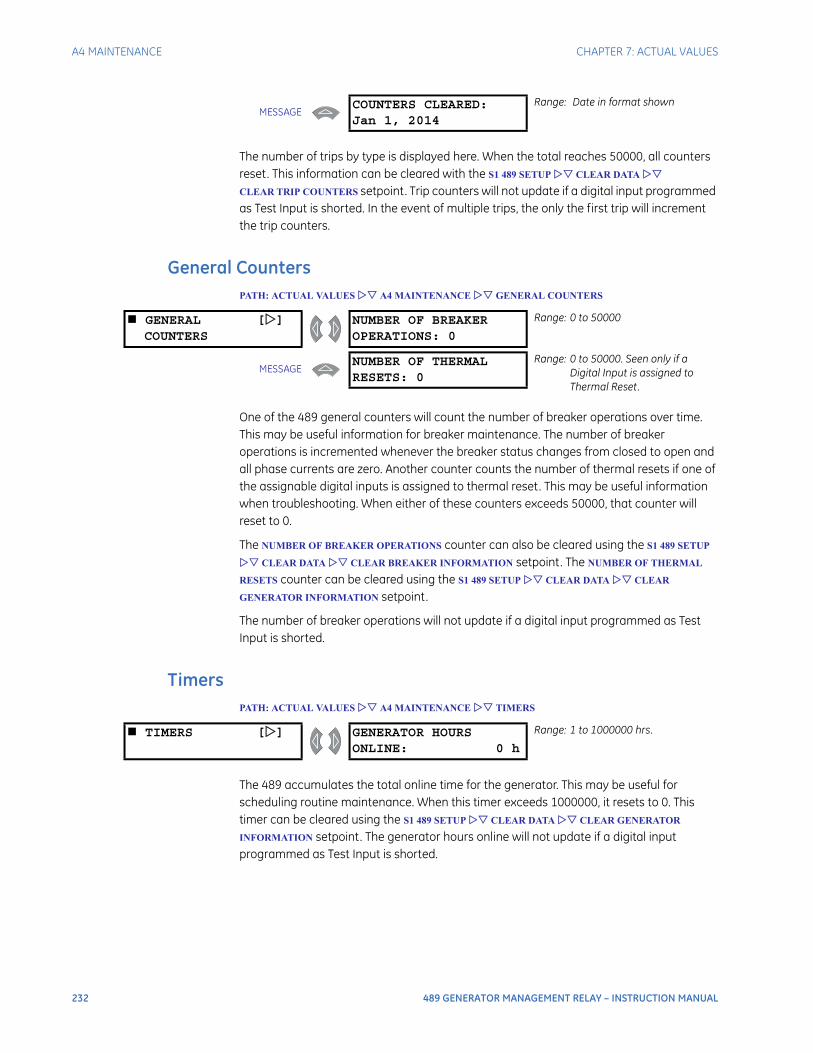
232 489 GENERATOR MANAGEMENT RELAY – INSTRUCTION MANUAL
A4 MAINTENANCE CHAPTER 7: ACTUAL VALUES
The number of trips by type is displayed here. When the total reaches 50000, all counters reset. This information can be cleared with the S1 489 SETUP CLEAR DATA
CLEAR TRIP COUNTERS setpoint. Trip counters will not update if a digital input programmed as Test Input is shorted. In the event of multiple trips, the only the first trip will increment the trip counters.
General CountersPATH: ACTUAL VALUES A4 MAINTENANCE GENERAL COUNTERS
One of the 489 general counters will count the number of breaker operations over time. This may be useful information for breaker maintenance. The number of breaker operations is incremented whenever the breaker status changes from closed to open and all phase currents are zero. Another counter counts the number of thermal resets if one of the assignable digital inputs is assigned to thermal reset. This may be useful information when troubleshooting. When either of these counters exceeds 50000, that counter will reset to 0.
The NUMBER OF BREAKER OPERATIONS counter can also be cleared using the S1 489 SETUP
CLEAR DATA CLEAR BREAKER INFORMATION setpoint. The NUMBER OF THERMAL
RESETS counter can be cleared using the S1 489 SETUP CLEAR DATA CLEAR
GENERATOR INFORMATION setpoint.
The number of breaker operations will not update if a digital input programmed as Test Input is shorted.
TimersPATH: ACTUAL VALUES A4 MAINTENANCE TIMERS
The 489 accumulates the total online time for the generator. This may be useful for scheduling routine maintenance. When this timer exceeds 1000000, it resets to 0. This timer can be cleared using the S1 489 SETUP CLEAR DATA CLEAR GENERATOR
INFORMATION setpoint. The generator hours online will not update if a digital input programmed as Test Input is shorted.
MESSAGECOUNTERS CLEARED:Jan 1, 2014
Range: Date in format shown
GENERAL []COUNTERS
NUMBER OF BREAKEROPERATIONS: 0
Range: 0 to 50000
MESSAGENUMBER OF THERMALRESETS: 0
Range: 0 to 50000. Seen only if a Digital Input is assigned to Thermal Reset.
TIMERS [] GENERATOR HOURSONLINE: 0 h
Range: 1 to 1000000 hrs.
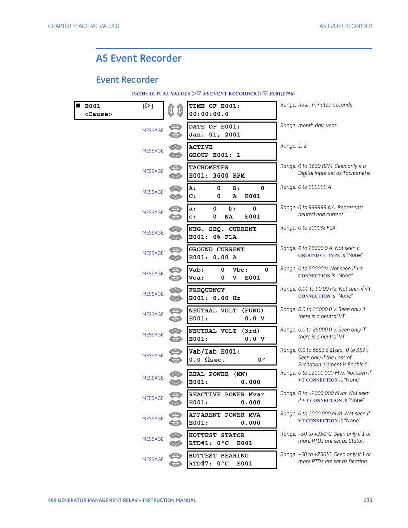
CHAPTER 7: ACTUAL VALUES A5 EVENT RECORDER
489 GENERATOR MANAGEMENT RELAY – INSTRUCTION MANUAL 233
A5 Event Recorder
Event RecorderPATH: ACTUAL VALUES A5 EVENT RECORDER E001(E256)
E001 []<Cause>
TIME OF E001:00:00:00.0
Range: hour: minutes: seconds
MESSAGEDATE OF E001:Jan. 01, 2001
Range: month day, year
MESSAGEACTIVEGROUP E001: 1
Range: 1, 2
MESSAGETACHOMETERE001: 3600 RPM
Range: 0 to 3600 RPM. Seen only if a Digital Input set as Tachometer
MESSAGEA: 0 B: 0C: 0 A E001
Range: 0 to 999999 A
MESSAGEa: 0 b: 0c: 0 NA E001
Range: 0 to 999999 NA. Represents neutral end current.
MESSAGENEG. SEQ. CURRENTE001: 0% FLA
Range: 0 to 2000% FLA
MESSAGEGROUND CURRENTE001: 0.00 A
Range: 0 to 20000.0 A. Not seen if GROUND CT TYPE is “None”.
MESSAGEVab: 0 Vbc: 0Vca: 0 V E001
Range: 0 to 50000 V. Not seen if VT
CONNECTION is “None”.
MESSAGEFREQUENCYE001: 0.00 Hz
Range: 0.00 to 90.00 Hz. Not seen if VT
CONNECTION is “None”.
MESSAGENEUTRAL VOLT (FUND)E001: 0.0 V
Range: 0.0 to 25000.0 V. Seen only if there is a neutral VT.
MESSAGENEUTRAL VOLT (3rd)E001: 0.0 V
Range: 0.0 to 25000.0 V. Seen only if there is a neutral VT.
MESSAGEVab/Iab E001:0.0 Ωsec. 0°
Range: 0.0 to 6553.5 Ωsec., 0 to 359°. Seen only if the Loss of Excitation element is Enabled.
MESSAGEREAL POWER (MW)E001: 0.000
Range: 0 to ±2000.000 MW. Not seen if VT CONNECTION is “None”
MESSAGEREACTIVE POWER MvarE001: 0.000
Range: 0 to ±2000.000 Mvar. Not seen if VT CONNECTION is “None”
MESSAGEAPPARENT POWER MVAE001: 0.000
Range: 0 to 2000.000 MVA. Not seen if VT CONNECTION is “None”
MESSAGEHOTTEST STATORRTD#1: 0°C E001
Range: –50 to +250°C. Seen only if 1 or more RTDs are set as Stator.
MESSAGEHOTTEST BEARINGRTD#7: 0°C E001
Range: –50 to +250°C. Seen only if 1 or more RTDs are set as Bearing.
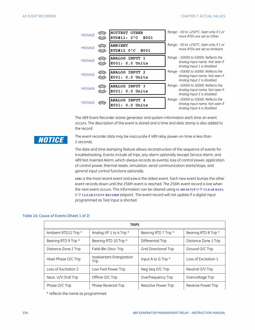
234 489 GENERATOR MANAGEMENT RELAY – INSTRUCTION MANUAL
A5 EVENT RECORDER CHAPTER 7: ACTUAL VALUES
The 489 Event Recorder stores generator and system information each time an event occurs. The description of the event is stored and a time and date stamp is also added to the record.
The event recorder data may be inaccurate if 489 relay power-on time is less than 2 seconds.
The date and time stamping feature allows reconstruction of the sequence of events for troubleshooting. Events include all trips, any alarm optionally (except Service Alarm, and 489 Not Inserted Alarm, which always records as events), loss of control power, application of control power, thermal resets, simulation, serial communication starts/stops, and general input control functions optionally.
E001 is the most recent event and E256 is the oldest event. Each new event bumps the other event records down until the 256th event is reached. The 256th event record is lost when the next event occurs. This information can be cleared using S1 489 SETUP CLEAR DATA
CLEAR EVENT RECORD setpoint. The event record will not update if a digital input programmed as Test Input is shorted.
MESSAGEHOTTEST OTHERRTD#11: 0°C E001
Range: –50 to +250°C. Seen only if 1 or more RTDs are set as Other.
MESSAGEAMBIENTRTD#12 0°C E001
Range: –50 to +250°C. Seen only if 1 or more RTDs are set as Ambient.
MESSAGEANALOG INPUT 1E001: 0.0 Units
Range: –50000 to 50000. Reflects the Analog Input name. Not seen if Analog Input 1 is disabled.
MESSAGEANALOG INPUT 2E001: 0.0 Units
Range: –50000 to 50000. Reflects the Analog Input name. Not seen if Analog Input 2 is disabled.
MESSAGEANALOG INPUT 3E001: 0.0 Units
Range: –50000 to 50000. Reflects the Analog Input name. Not seen if Analog Input 3 is disabled.
MESSAGEANALOG INPUT 4E001: 0.0 Units
Range: –50000 to 50000. Reflects the Analog Input name. Not seen if Analog Input 4 is disabled.
Table 14: Cause of Events (Sheet 1 of 2)
TRIPS
Ambient RTD12 Trip * Analog I/P 1 to 4 Trip * Bearing RTD 7 Trip * Bearing RTD 8 Trip *
Bearing RTD 9 Trip * Bearing RTD 10 Trip * Differential Trip Distance Zone 1 Trip
Distance Zone 2 Trip Field-Bkr Discr. Trip Gnd Directional Trip Ground O/C Trip
Hiset Phase O/C Trip Inadvertent Energization Trip Input A to G Trip * Loss of Excitation 1
Loss of Excitation 2 Low Fwd Power Trip Neg Seq O/C Trip Neutral O/V Trip
Neut. U/V (3rd) Trip Offline O/C Trip Overfrequency Trip Overvoltage Trip
Phase O/C Trip Phase Reversal Trip Reactive Power Trip Reverse Power Trip
* reflects the name as programmed
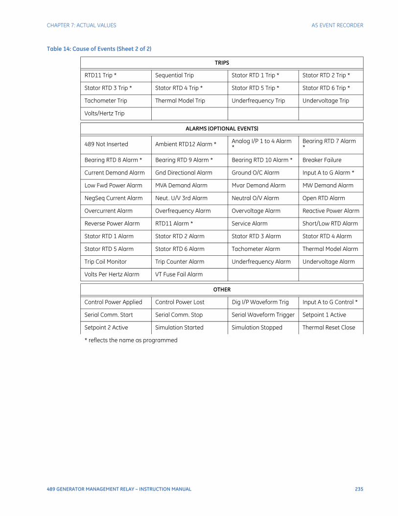
CHAPTER 7: ACTUAL VALUES A5 EVENT RECORDER
489 GENERATOR MANAGEMENT RELAY – INSTRUCTION MANUAL 235
RTD11 Trip * Sequential Trip Stator RTD 1 Trip * Stator RTD 2 Trip *
Stator RTD 3 Trip * Stator RTD 4 Trip * Stator RTD 5 Trip * Stator RTD 6 Trip *
Tachometer Trip Thermal Model Trip Underfrequency Trip Undervoltage Trip
Volts/Hertz Trip
ALARMS (OPTIONAL EVENTS)
489 Not Inserted Ambient RTD12 Alarm * Analog I/P 1 to 4 Alarm *
Bearing RTD 7 Alarm *
Bearing RTD 8 Alarm * Bearing RTD 9 Alarm * Bearing RTD 10 Alarm * Breaker Failure
Current Demand Alarm Gnd Directional Alarm Ground O/C Alarm Input A to G Alarm *
Low Fwd Power Alarm MVA Demand Alarm Mvar Demand Alarm MW Demand Alarm
NegSeq Current Alarm Neut. U/V 3rd Alarm Neutral O/V Alarm Open RTD Alarm
Overcurrent Alarm Overfrequency Alarm Overvoltage Alarm Reactive Power Alarm
Reverse Power Alarm RTD11 Alarm * Service Alarm Short/Low RTD Alarm
Stator RTD 1 Alarm Stator RTD 2 Alarm Stator RTD 3 Alarm Stator RTD 4 Alarm
Stator RTD 5 Alarm Stator RTD 6 Alarm Tachometer Alarm Thermal Model Alarm
Trip Coil Monitor Trip Counter Alarm Underfrequency Alarm Undervoltage Alarm
Volts Per Hertz Alarm VT Fuse Fail Alarm
OTHER
Control Power Applied Control Power Lost Dig I/P Waveform Trig Input A to G Control *
Serial Comm. Start Serial Comm. Stop Serial Waveform Trigger Setpoint 1 Active
Setpoint 2 Active Simulation Started Simulation Stopped Thermal Reset Close
Table 14: Cause of Events (Sheet 2 of 2)
TRIPS
* reflects the name as programmed
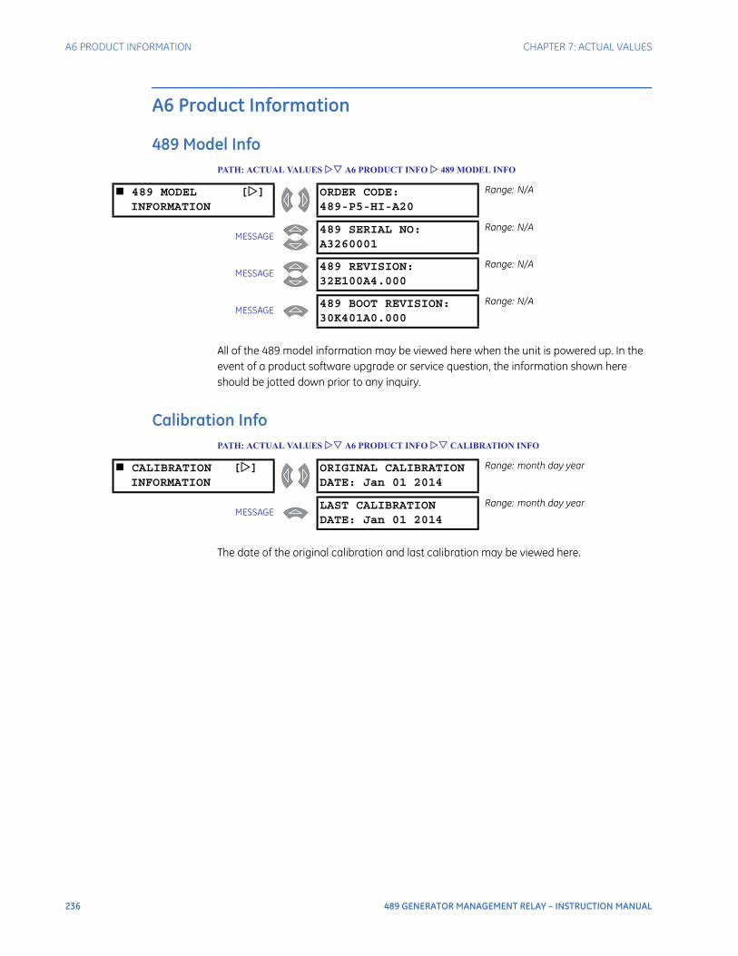
236 489 GENERATOR MANAGEMENT RELAY – INSTRUCTION MANUAL
A6 PRODUCT INFORMATION CHAPTER 7: ACTUAL VALUES
A6 Product Information
489 Model InfoPATH: ACTUAL VALUES A6 PRODUCT INFO 489 MODEL INFO
All of the 489 model information may be viewed here when the unit is powered up. In the event of a product software upgrade or service question, the information shown here should be jotted down prior to any inquiry.
Calibration InfoPATH: ACTUAL VALUES A6 PRODUCT INFO CALIBRATION INFO
The date of the original calibration and last calibration may be viewed here.
489 MODEL []INFORMATION
ORDER CODE:489-P5-HI-A20
Range: N/A
MESSAGE489 SERIAL NO:A3260001
Range: N/A
MESSAGE489 REVISION:32E100A4.000
Range: N/A
MESSAGE489 BOOT REVISION:30K401A0.000
Range: N/A
CALIBRATION []INFORMATION
ORIGINAL CALIBRATIONDATE: Jan 01 2014
Range: month day year
MESSAGELAST CALIBRATIONDATE: Jan 01 2014
Range: month day year
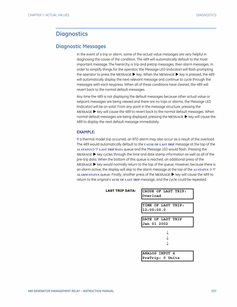
CHAPTER 7: ACTUAL VALUES DIAGNOSTICS
489 GENERATOR MANAGEMENT RELAY – INSTRUCTION MANUAL 237
Diagnostics
Diagnostic MessagesIn the event of a trip or alarm, some of the actual value messages are very helpful in diagnosing the cause of the condition. The 489 will automatically default to the most important message. The hierarchy is trip and pretrip messages, then alarm messages. In order to simplify things for the operator, the Message LED (indicator) will flash prompting the operator to press the MESSAGE key. When the MESSAGE key is pressed, the 489 will automatically display the next relevant message and continue to cycle through the messages with each keypress. When all of these conditions have cleared, the 489 will revert back to the normal default messages.
Any time the 489 is not displaying the default messages because other actual value or setpoint messages are being viewed and there are no trips or alarms, the Message LED (indicator) will be on solid. From any point in the message structure, pressing the MESSAGE key will cause the 489 to revert back to the normal default messages. When normal default messages are being displayed, pressing the MESSAGE key will cause the 489 to display the next default message immediately.
EXAMPLE:
If a thermal model trip occurred, an RTD alarm may also occur as a result of the overload. The 489 would automatically default to the CAUSE OF LAST TRIP message at the top of the A1 STATUS LAST TRIP DATA queue and the Message LED would flash. Pressing the MESSAGE key cycles through the time and date stamp information as well as all of the pre-trip data. When the bottom of this queue is reached, an additional press of the MESSAGE key would normally return to the top of the queue. However, because there is an alarm active, the display will skip to the alarm message at the top of the A1 STATUS
ALARM STATUS queue. Finally, another press of the MESSAGE key will cause the 489 to return to the original CAUSE OF LAST TRIP message, and the cycle could be repeated.
LAST TRIP DATA: CAUSE OF LAST TRIP:Overload
TIME OF LAST TRIP:12:00:00.0
DATE OF LAST TRIPJan 01 2002
↓↓↓
ANALOG INPUT 4PreTrip: 0 Units
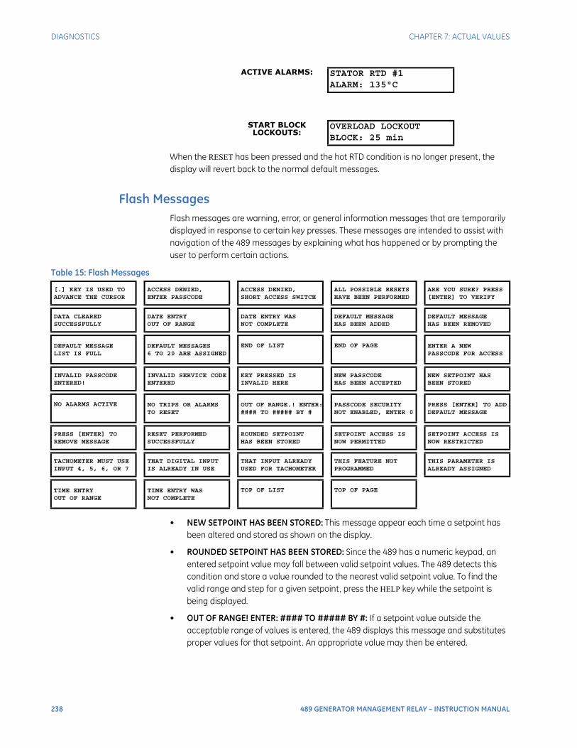
238 489 GENERATOR MANAGEMENT RELAY – INSTRUCTION MANUAL
DIAGNOSTICS CHAPTER 7: ACTUAL VALUES
When the RESET has been pressed and the hot RTD condition is no longer present, the display will revert back to the normal default messages.
Flash MessagesFlash messages are warning, error, or general information messages that are temporarily displayed in response to certain key presses. These messages are intended to assist with navigation of the 489 messages by explaining what has happened or by prompting the user to perform certain actions.
• NEW SETPOINT HAS BEEN STORED: This message appear each time a setpoint has been altered and stored as shown on the display.
• ROUNDED SETPOINT HAS BEEN STORED: Since the 489 has a numeric keypad, an entered setpoint value may fall between valid setpoint values. The 489 detects this condition and store a value rounded to the nearest valid setpoint value. To find the valid range and step for a given setpoint, press the HELP key while the setpoint is being displayed.
• OUT OF RANGE! ENTER: #### TO ##### BY #: If a setpoint value outside the acceptable range of values is entered, the 489 displays this message and substitutes proper values for that setpoint. An appropriate value may then be entered.
ACTIVE ALARMS: STATOR RTD #1ALARM: 135°C
START BLOCK LOCKOUTS:
OVERLOAD LOCKOUTBLOCK: 25 min
Table 15: Flash Messages
[.] KEY IS USED TOADVANCE THE CURSOR
ACCESS DENIED,ENTER PASSCODE
ACCESS DENIED,SHORT ACCESS SWITCH
ALL POSSIBLE RESETSHAVE BEEN PERFORMED
ARE YOU SURE? PRESS[ENTER] TO VERIFY
DATA CLEAREDSUCCESSFULLY
DATE ENTRYOUT OF RANGE
DATE ENTRY WASNOT COMPLETE
DEFAULT MESSAGEHAS BEEN ADDED
DEFAULT MESSAGEHAS BEEN REMOVED
DEFAULT MESSAGELIST IS FULL
DEFAULT MESSAGES6 TO 20 ARE ASSIGNED
END OF LIST END OF PAGE ENTER A NEWPASSCODE FOR ACCESS
INVALID PASSCODEENTERED!
INVALID SERVICE CODEENTERED
KEY PRESSED ISINVALID HERE
NEW PASSCODEHAS BEEN ACCEPTED
NEW SETPOINT HASBEEN STORED
NO ALARMS ACTIVE NO TRIPS OR ALARMSTO RESET
OUT OF RANGE.! ENTER:#### TO ##### BY #
PASSCODE SECURITYNOT ENABLED, ENTER 0
PRESS [ENTER] TO ADDDEFAULT MESSAGE
PRESS [ENTER] TOREMOVE MESSAGE
RESET PERFORMEDSUCCESSFULLY
ROUNDED SETPOINTHAS BEEN STORED
SETPOINT ACCESS ISNOW PERMITTED
SETPOINT ACCESS ISNOW RESTRICTED
TACHOMETER MUST USEINPUT 4, 5, 6, OR 7
THAT DIGITAL INPUTIS ALREADY IN USE
THAT INPUT ALREADYUSED FOR TACHOMETER
THIS FEATURE NOTPROGRAMMED
THIS PARAMETER ISALREADY ASSIGNED
TIME ENTRYOUT OF RANGE
TIME ENTRY WASNOT COMPLETE
TOP OF LIST TOP OF PAGE

CHAPTER 7: ACTUAL VALUES DIAGNOSTICS
489 GENERATOR MANAGEMENT RELAY – INSTRUCTION MANUAL 239
• ACCESS DENIED, SHORT ACCESS SWITCH: The Access Switch must be shorted to store any setpoint values. If this message appears and it is necessary to change a setpoint, short the Access terminals C1 and C2.
• ACCESS DENIED, ENTER PASSCODE: The 489 has a passcode security feature. If this feature is enabled, not only must the Access Switch terminals be shorted, but a valid passcode must also be entered. If the correct passcode has been lost or forgotten, contact the factory with the encrypted access code. All passcode features may be found in the S1 489 SETUP PASSCODE setpoints menu.
• INVALID PASSCODE ENTERED: This flash message appears if an invalid passcode is entered for the passcode security feature.
• NEW PASSCODE HAS BEEN ACCEPTED: This message will appear as an acknowledge that the new passcode has been accepted when changing the passcode for the passcode security feature.
• PASSCODE SECURITY NOT ENABLED, ENTER 0: The passcode security feature is disabled whenever the passcode is zero (factory default). Any attempts to enter a passcode when the feature is disabled results in this flash message, prompting the user to enter “0” as the passcode. When this has been done, the feature may be enabled by entering a non-zero passcode.
• ENTER A NEW PASSCODE FOR ACCESS: The passcode security feature is disabled if the passcode is zero. If the CHANGE PASSCODE SETPOINT is entered as yes, this flash message appears prompting the user to enter a non-zero passcode and enable the passcode security feature.
• SETPOINT ACCESS IS NOW PERMITTED: Any time the passcode security feature is enabled and a valid passcode is entered, this flash message appears to notify that setpoints may now be altered and stored.
• SETPOINT ACCESS IS NOW RESTRICTED: If the passcode security feature is enabled and a valid passcode entered, this message appears when the S1 489 SETUP
PASSCODE SETPOINT ACCESS setpoint is altered to “Restricted”. This message also appears any time that setpoint access is permitted and the access jumper is removed.
• DATE ENTRY WAS NOT COMPLETE: Since the DATE setpoint has a special format (entered as MM/DD/YYYY), this message appears and the new value will not be stored if the ENTER key is pressed before all of the information has been entered. Another attempt will have to be made with the complete information.
• DATE ENTRY WAS OUT OF RANGE: Appears if an invalid entry is made for the DATE (for example, 15 entered for the month).
• TIME ENTRY WAS NOT COMPLETE: Since the TIME setpoint has a special format (entered as HH/MM/SS.s), this message appears and the new value will not be stored if the ENTER key is pressed before all of the information has been entered. Another attempt will have to be made with the complete information.
• TIME ENTRY WAS OUT OF RANGE: Appears if an invalid entry is made for the TIME (for example, 35 entered for the hour).
• NO TRIPS OR ALARMS TO RESET: Appears if the RESET key is pressed when there are no trips or alarms present.
• RESET PERFORMED SUCCESSFULLY: If all trip and alarm features that are active can be cleared (that is, the conditions that caused these trips and/or alarms are no longer

240 489 GENERATOR MANAGEMENT RELAY – INSTRUCTION MANUAL
DIAGNOSTICS CHAPTER 7: ACTUAL VALUES
present), then this message appears when a reset is performed, indicating that all trips and alarms have been cleared.
• ALL POSSIBLE RESETS HAVE BEEN PERFORMED: If only some of the trip and alarm features that are active can be cleared (that is, the conditions that caused some of these trips and/or alarms are still present), then this message appears when a reset is performed, indicating that only trips and alarms that could be reset have been reset.
• ARE YOU SURE? PRESS [ENTER] TO VERIFY: If the RESET key is pressed and resetting of any trip or alarm feature is possible, this message appears to verify the operation. If RESET is pressed again while this message is displayed, the reset will be performed.
• PRESS [ENTER] TO ADD DEFAULT MESSAGE: Appears if the decimal [.] key, immediately followed by the ENTER key, is entered anywhere in the actual value message structure. This message prompts the user to press ENTER to add a new default message. To add a new default message, ENTER must be pressed while this message is being displayed.
• DEFAULT MESSAGE HAS BEEN ADDED: Appears anytime a new default message is added to the default message list.
• DEFAULT MESSAGE LIST IS FULL: Appears if an attempt is made to add a new default message to the default message list when 20 messages are already assigned. To add a new message, one of the existing messages must be removed.
• PRESS [ENTER] TO REMOVE MESSAGE: Appears if the decimal [.] key, immediately followed by the ENTER key, is entered in the S1 489 SETUP DEFAULT MESSAGES setpoint page. This message prompts the user to press ENTER to remove a default message. To remove the default message, ENTER must be pressed while this message is being displayed.
• DEFAULT MESSAGE HAS BEEN REMOVED: Appears anytime a default message is removed from the default message list.
• DEFAULT MESSAGES 6 of 20 ARE ASSIGNED: Appears anytime the S1 489 SETUP
DEFAULT MESSAGES setpoint page is entered, notifying the user of the number of default messages assigned.
• INVALID SERVICE CODE ENTERED: Appears if an invalid code is entered in the S12 489
TESTING FACTORY SERVICE setpoints page.
• KEY PRESSED HERE IS INVALID: Under certain situations, certain keys have no function (for example, any number key while viewing actual values). This message appears if a keypress has no current function.
• DATA CLEARED SUCCESSFULLY: Confirms that data is reset in the S1 489 SETUP
CLEAR DATA setpoints page.
• [.] KEY IS USED TO ADVANCE THE CURSOR: Appears immediately to prompt the use of the [.] key for cursor control anytime a setpoint requiring text editing is viewed. If the setpoint is not altered for 1 minute, this message flashes again.
• TOP OF PAGE: This message will indicate when the top of a page has been reached.
• BOTTOM OF PAGE: This message will indicate when the bottom of a page has been reached.
• TOP OF LIST: This message will indicate when the top of subgroup has been reached.

CHAPTER 7: ACTUAL VALUES DIAGNOSTICS
489 GENERATOR MANAGEMENT RELAY – INSTRUCTION MANUAL 241
• END OF LIST: This message will indicate when the bottom of a subgroup has been reached.
• NO ALARMS ACTIVE: If an attempt is made to enter the Alarm Status message subgroup, but there are no active alarms, this message will appear.
• THIS FEATURE NOT PROGRAMMED: If an attempt is made to enter an actual value message subgroup, when the setpoints are not configured for that feature, this message will appear.
• THIS PARAMETER IS ALREADY ASSIGNED: A given analog output parameters can only be assigned to one output. If an attempt is made to assign a parameter to a second output, this message will appear.
• THAT INPUT ALREADY USED FOR TACHOMETER: If a digital input is assigned to the tachometer function, it cannot be used for any other digital input function. If an attempt is made to assign a digital input to a function when it is already assigned to tachometer, this message will appear.
• TACHOMETER MUST USE INPUT 4, 5, 6, or 7: Only digital inputs 4, 5, 6, or 7 may be used for the tachometer function. If an attempt is made to assign inputs 1,2,3, or 4 to the tachometer function, this message will appear.
• THAT DIGITAL INPUT IS ALREADY IN USE: If an attempt is made to assign a digital input to tachometer when it is already assigned to another function, this message will appear.
• To edit use VALUE UP or VALUE DOWN key: If a numeric key is pressed on a setpoint parameter that is not numeric, this message will prompt the user to use the value keys.
• GROUP 1 SETPOINT HAS BEEN STORED: This message appear each time a setpoint has been altered and stored to setpoint Group 1 as shown on the display.
• GROUP 2 SETPOINT HAS BEEN STORED: This message appear each time a setpoint has been altered and stored to setpoint Group 2 as shown on the display.

242 489 GENERATOR MANAGEMENT RELAY – INSTRUCTION MANUAL
DIAGNOSTICS CHAPTER 7: ACTUAL VALUES
489 GENERATOR MANAGEMENT RELAY – INSTRUCTION MANUAL 243
489 Generator Management Relay
Chapter 8: Testing
Testing
Test Setup
DescriptionThe purpose of this testing description is to demonstrate the procedures necessary to perform a complete functional test of all the 489 hardware while also testing firmware/hardware interaction in the process. Since the 489 is packaged in a drawout case, a demo case (metal carry case in which the 489 may be mounted) may be useful for creating a portable test set with a wiring harness for all of the inputs and outputs. Testing of the relay during commissioning using a primary injection test set will ensure that CTs and wiring are correct and complete.
The 489 tests are listed below. For the following tests refer to Secondary Current Injection Testing on page 245:
1. Output Current Accuracy Test
2. Phase Voltage Input Accuracy Test
3. Ground, Neutral, and Differential Current Accuracy Test
4. Neutral Voltage (Fundamental) Accuracy Test
5. Negative Sequence Current Accuracy Test
6. RTD Accuracy Test
7. Digital Input and Trip Coil Supervision Accuracy Test
8. Analog Input and Outputs Test
9. Output Relay Test
10. Overload Curve Test
11. Power Measurement Test
12. Reactive Power Test

244 489 GENERATOR MANAGEMENT RELAY – INSTRUCTION MANUAL
TEST SETUP CHAPTER 8: TESTING
13. Voltage Phase Reversal Test
14. For the following tests refer to Secondary Injection Setup #2 on page 257:
15. GE Multilin (HGF) Ground Current Accuracy Test
16. Neutral Voltage (3rd Harmonic) Accuracy Test
17. Phase Differential Trip Test
18. For the following test refer to Secondary Injection Test Setup #3 on page 261:
19. Voltage Restrained Overcurrent Test
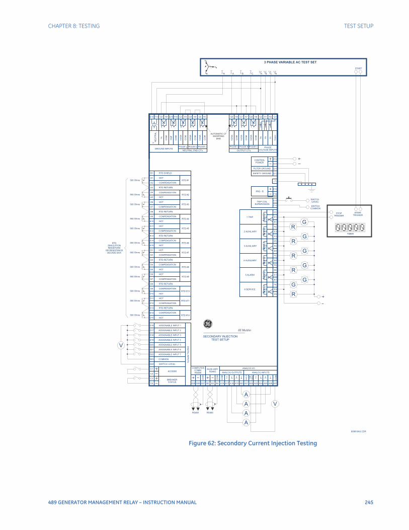
CHAPTER 8: TESTING TEST SETUP
489 GENERATOR MANAGEMENT RELAY – INSTRUCTION MANUAL 245
Figure 62: Secondary Current Injection Testing
A2
A5
A7
A10
A12
A15
D2
D7
D12
D10
D15
D16
D20V
A
V
G
G
G
G
G
R
R
R
R
G
R
A
A
A
D18
D22
C2
D17
D21
C1
D19
D23
C3
D24
C4 D25
RS485 RS485
B2 A16 A23D26 B3 A21A17 A24A19 A26D27
COMPUTER
COMM.
RS485
AUXILIARY
RS485ANALOG OUTPUTS ANALOG INPUTS
ANALOG I/O
B4 A22A18 A25A20 A27
CO
M
CO
M
SH
IELD
2+
2+
CO
M
+24
VD
C
1+
1+
3+
3+
4+
4+ -
CO
M
D5
A1
A4
A6
A9
A11
A14
D1
D6
D11
D9
D14
D4
B1
500 Ohms
500 Ohms
500 Ohms
500 Ohms
RTD
SIMULATION
RESISTORS
OR RESISTANCE
DECADE BOX
500 Ohms
500 Ohms
500 Ohms
500 Ohms
500 Ohms
500 Ohms
500 Ohms
500 Ohms
A3
A8
A13
D3
D8
D13
COMPENSATION
COMPENSATION
COMPENSATION
COMPENSATION
COMPENSATION
COMPENSATION
HOT
COMPENSATION
COMPENSATION
COMPENSATION
COMPENSATION
COMPENSATION
COMPENSATION
HOT
HOT
HOT
HOT
HOT
HOT
HOT
HOT
HOT
HOT
ASSIGNABLE INPUT 1
ASSIGNABLE INPUT 2
ASSIGNABLE INPUT 3
ASSIGNABLE INPUT 4
ASSIGNABLE INPUT 5
ASSIGNABLE INPUT 6
ASSIGNABLE INPUT 7
COMMON
SWITCH +24Vdc
ACCESS
DIG
ITA
LIN
PU
TS
BREAKER
STATUS
HOT
RTD SHIELD
RTD RETURN
RTD RETURN
RTD RETURN
RTD RETURN
RTD RETURN
RTD RETURN
RTD #1
RTD #2
RTD #3
RTD #4
RTD #5
RTD #6
RTD #7
RTD #9
RTD #11
RTD #10
RTD #12
RTD #8
CONTROL
POWER
IRIG - B
SAFETY GROUND
TIMER
STOP
TRIGGER
SWITCH
+24VAC
SWITCH
COMMON
START
TRIGGER
START
TRIP COIL
SUPERVISION
1 TRIP
3 AUXILIARY
5 ALARM
2 AUXILIARY
4 AUXILIARY
6 SERVICE
SECONDARY INJECTION
TEST SETUP
FILTER GROUND
H12
G12
E12
E11
E2
E5
E8
F2
F5
F8
H11
G11
F12
F11
F1
F4
F7
E3
E6
E9
E1
E4
E7
F3
F6
F9
g
E10
V
NE
UT
RA
L
1A
HG
F
1A
/5A
1A
/5A
1A
/5A
1A
/5A
1A
/5A
1A
/5A
CO
M
CO
M
CO
M
CO
M
CO
M
PHASE a PHASE b PHASE c PHASE A PHASE B PHASE C
CO
M
CO
M
CO
M
Va
Vb
Vco
m
Vc
H10 G3 G6H4 H7 H1F10
A B C NA B CNV V V VI I II
3 PHASE VARIABLE AC TEST SET
GROUND INPUTSNEUTRAL END CT's OUTPUT CT's
PHASE
VOLTAGE INPUTS
G9 H3 H6G5 G8 H2
808818A3.CDR
G10H9 G4 G7 G2H5 H8 G1
AUTOMATIC CT
SHORTING
BAR
VC
VA
VB
GE Multilin

246 489 GENERATOR MANAGEMENT RELAY – INSTRUCTION MANUAL
HARDWARE FUNCTIONAL TESTS CHAPTER 8: TESTING
Hardware Functional Tests
Output Current AccuracyThe specification for output and neutral end current input is ±0.5% of 2 × CT when the injected current is less than 2 × CT. Perform the steps below to verify accuracy.
Alter the following setpoint:
S2 SYSTEM SETUP CURRENT SENSING PHASE CT PRIMARY: “1000 A”
Measured values should be ±10 A.
Inject the values shown in the table below and verify accuracy of the measured values.
View the measured values in the A2 METERING DATA CURRENT
METERING menu.
Phase Voltage Input AccuracyThe specification for phase voltage input accuracy is ±0.5% of full scale (200 V). Perform the steps below to verify accuracy.
Alter the following setpoints in the S2 SYSTEM SETUP VOLTAGE
SENSING menu:
VT CONNECTION TYPE: “Wye”
VOLTAGE TRANSFORMER RATIO: “10.00:1”
Measured values should be ±1.0 V.
Apply the voltage values shown in the table and verify accuracy of the measured values.
View the measured values in the A2 METERING DATA VOLTAGE
METERING menu.
Injected Current Expected Current
Measured Current
1 A Unit 5 A Unit Phase A Phase B Phase C
0.1 A 0.5 A 100 A
0.2 A 1.0 A 200 A
0.5 A 2.5 A 500 A
1 A 5 A 1000 A
1.5 A 7.5 A 1500 A
2 A 10 A 2000 A
Applied Line-Neutral Voltage
Expected Voltage Reading
Measured Voltage
A-N B-N C-N
30 V 300 V
50 V 500 V
100 V 1000 V
150 V 1500 V
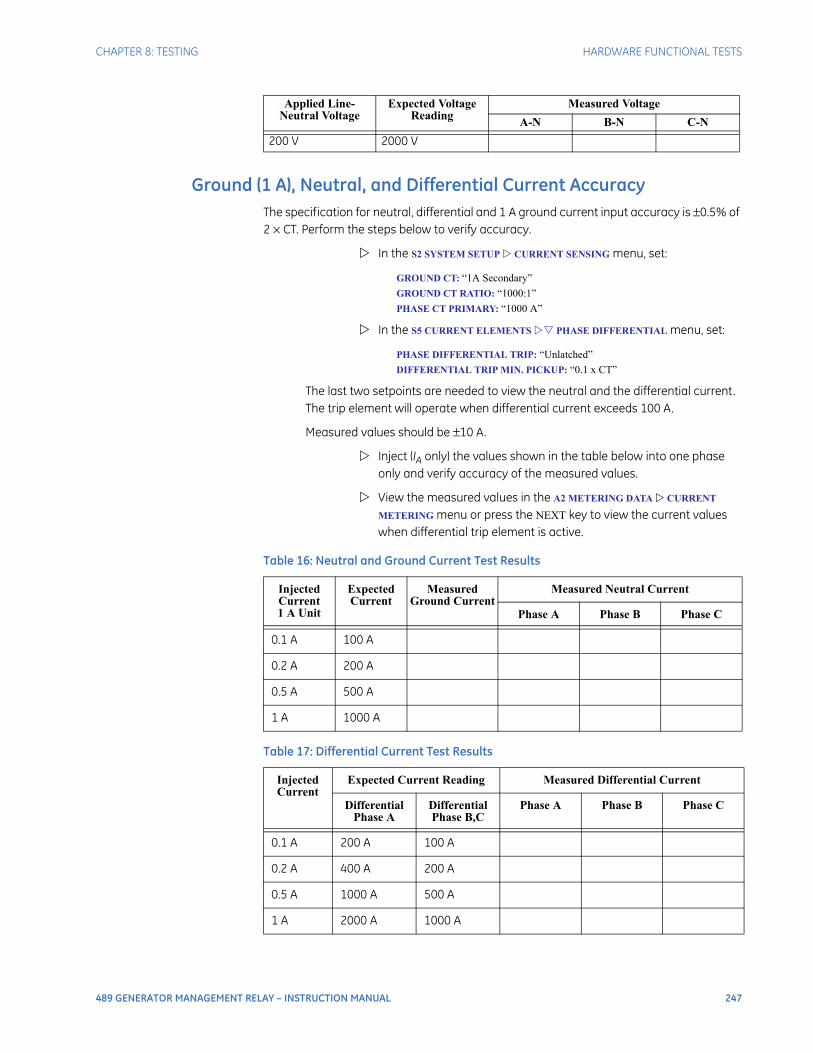
CHAPTER 8: TESTING HARDWARE FUNCTIONAL TESTS
489 GENERATOR MANAGEMENT RELAY – INSTRUCTION MANUAL 247
Ground (1 A), Neutral, and Differential Current AccuracyThe specification for neutral, differential and 1 A ground current input accuracy is ±0.5% of 2 × CT. Perform the steps below to verify accuracy.
In the S2 SYSTEM SETUP CURRENT SENSING menu, set:
GROUND CT: “1A Secondary”
GROUND CT RATIO: “1000:1”
PHASE CT PRIMARY: “1000 A”
In the S5 CURRENT ELEMENTS PHASE DIFFERENTIAL menu, set:
PHASE DIFFERENTIAL TRIP: “Unlatched”
DIFFERENTIAL TRIP MIN. PICKUP: “0.1 x CT”
The last two setpoints are needed to view the neutral and the differential current. The trip element will operate when differential current exceeds 100 A.
Measured values should be ±10 A.
Inject (IA only) the values shown in the table below into one phase only and verify accuracy of the measured values.
View the measured values in the A2 METERING DATA CURRENT
METERING menu or press the NEXT key to view the current values when differential trip element is active.
200 V 2000 V
Applied Line-Neutral Voltage
Expected Voltage Reading
Measured Voltage
A-N B-N C-N
Table 16: Neutral and Ground Current Test Results
Injected Current1 A Unit
Expected Current
Measured Ground Current
Measured Neutral Current
Phase A Phase B Phase C
0.1 A 100 A
0.2 A 200 A
0.5 A 500 A
1 A 1000 A
Table 17: Differential Current Test Results
Injected Current
Expected Current Reading Measured Differential Current
Differential Phase A
Differential Phase B,C
Phase A Phase B Phase C
0.1 A 200 A 100 A
0.2 A 400 A 200 A
0.5 A 1000 A 500 A
1 A 2000 A 1000 A
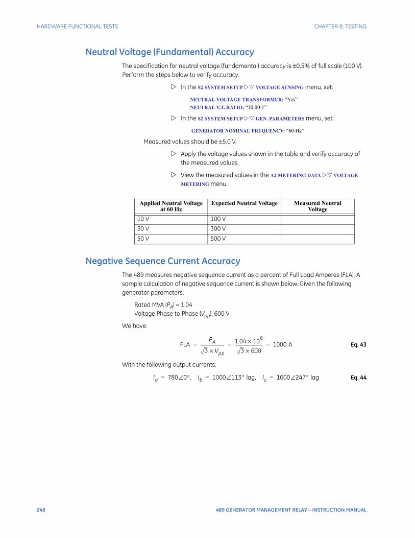
248 489 GENERATOR MANAGEMENT RELAY – INSTRUCTION MANUAL
HARDWARE FUNCTIONAL TESTS CHAPTER 8: TESTING
Neutral Voltage (Fundamental) AccuracyThe specification for neutral voltage (fundamental) accuracy is ±0.5% of full scale (100 V). Perform the steps below to verify accuracy.
In the S2 SYSTEM SETUP VOLTAGE SENSING menu, set:
NEUTRAL VOLTAGE TRANSFORMER: “Yes”
NEUTRAL V.T. RATIO: “10.00:1”
In the S2 SYSTEM SETUP GEN. PARAMETERS menu, set:
GENERATOR NOMINAL FREQUENCY: “60 Hz”
Measured values should be ±5.0 V.
Apply the voltage values shown in the table and verify accuracy of the measured values.
View the measured values in the A2 METERING DATA VOLTAGE
METERING menu.
Negative Sequence Current AccuracyThe 489 measures negative sequence current as a percent of Full Load Amperes (FLA). A sample calculation of negative sequence current is shown below. Given the following generator parameters:
Rated MVA (PA) = 1.04Voltage Phase to Phase (Vpp): 600 V
We have:
Eq. 43
With the following output currents:
Eq. 44
Applied Neutral Voltage at 60 Hz
Expected Neutral Voltage Measured Neutral Voltage
10 V 100 V
30 V 300 V
50 V 500 V
FLAPA
3 Vpp×---------------------- 1.04 106×
3 600×-------------------------- 1000 A= = =
Ia 780 0°, Ib∠ 1000 113° lag, Ic∠ 1000 247° lag∠= = =
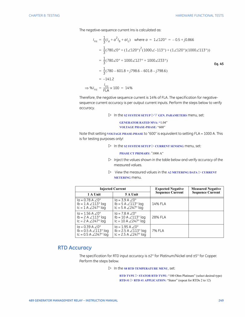
CHAPTER 8: TESTING HARDWARE FUNCTIONAL TESTS
489 GENERATOR MANAGEMENT RELAY – INSTRUCTION MANUAL 249
The negative-sequence current Ins is calculated as:
Eq. 45
Therefore, the negative sequence current is 14% of FLA. The specification for negative-sequence current accuracy is per output current inputs. Perform the steps below to verify accuracy.
In the S2 SYSTEM SETUP GEN. PARAMETERS menu, set:
GENERATOR RATED MVA: “1.04”
VOLTAGE PHASE-PHASE: “600”
Note that setting VOLTAGE PHASE-PHASE to “600” is equivalent to setting FLA = 1000 A. This is for testing purposes only!
In the S2 SYSTEM SETUP CURRENT SENSING menu, set:
PHASE CT PRIMARY: “1000 A”
Inject the values shown in the table below and verify accuracy of the measured values.
View the measured values in the A2 METERING DATA CURRENT
METERING menu.
RTD AccuracyThe specification for RTD input accuracy is ±2° for Platinum/Nickel and ±5° for Copper. Perform the steps below.
In the S8 RTD TEMPERATURE MENU, set:
RTD TYPE STATOR RTD TYPE: “100 Ohm Platinum” (select desired type)
RTD #1 RTD #1 APPLICATION: “Stator” (repeat for RTDs 2 to 12)
Injected Current Expected Negative Sequence Current
Measured Negative Sequence Current
1 A Unit 5 A Unit
Ia = 0.78 A ∠0°Ib = 1 A ∠113° lagIc = 1 A ∠247° lag
Ia = 3.9 A ∠0°Ib = 5 A ∠113° lagIc = 5 A ∠247° lag
14% FLA
Ia = 1.56 A ∠0°Ib = 2 A ∠113° lagIc = 2 A ∠247° lag
Ia = 7.8 A ∠0°Ib = 10 A ∠113° lagIc = 10 A ∠247° lag
28% FLA
Ia = 0.39 A ∠0°Ib = 0.5 A ∠113° lagIc = 0.5 A ∠247° lag
Ia = 1.95 A ∠0°Ib = 2.5 A ∠113° lagIc = 2.5 A ∠247° lag
7% FLA
Ins13--- Ia a2Ib aIc+ +( ) where a 1 120°∠ 0.5– j0.866+= = =
13--- 780 0°∠ 1 120°∠( )2 1000 113°–∠( ) 1 120°∠( ) 1000 113°∠( )+ +( )=
13--- 780 0°∠ 1000 127°∠ 1000 233°∠+ +( )=
13--- 780 601.8– j798.6 601.8– j798.6–+( )=
141.2–=
%InsIns
FLA--------- 100× 14%= =

250 489 GENERATOR MANAGEMENT RELAY – INSTRUCTION MANUAL
HARDWARE FUNCTIONAL TESTS CHAPTER 8: TESTING
Measured values should be ±2°C / ±4°F for platinum/nickel and ±5°C / ±9°F for copper.
Alter the resistance applied to the RTD inputs as shown below to simulate RTDs and verify accuracy.
View the measured values in A2 METERING DATA TEMPERATURE.
Applied Resistance
100 Ω Platinum
Expected RTD Temperature Reading
Measured RTD TemperatureSelect One: ____°C ____°F
°C °F 1 2 3 4 5 6 7 8 9 10 11 12
84.27 Ω –40°C –40°F
100.00 Ω 0°C 32°F
119.39 Ω 50°C 122°F
138.50 Ω 100°C 212°F
157.32 Ω 150°C 302°F
175.84 Ω 200°C 392°F
194.08 Ω 250°C 482°F
Applied Resistance
120 Ω Nickel
Expected RTD Temperature Reading
Measured RTD TemperatureSelect One: ____°C ____°F
°C °F 1 2 3 4 5 6 7 8 9 10 11 12
92.76 Ω –40°C –40°F
120.00 Ω 0°C 32°F
157.74 Ω 50°C 122°F
200.64 Ω 100°C 212°F
248.95 Ω 150°C 302°F
303.46 Ω 200°C 392°F
366.53 Ω 250°C 482°F
Applied Resistance
100 Ω Nickel
Expected RTD Temperature Reading
Measured RTD TemperatureSelect One: ____°C ____°F
°C °F 1 2 3 4 5 6 7 8 9 10 11 12
77.30 Ω –40°C –40°F
100.00 Ω 0°C 32°F
131.45 Ω 50°C 122°F
167.20 Ω 100°C 212°F
207.45 Ω 150°C 302°F
252.88 Ω 200°C 392°F
305.44 Ω 250°C 482°F
Applied Resistance
10 Ω Copper
Expected RTD Temperature Reading
Measured RTD TempeatureSelect One: ____°C ____°F
°C °F 1 2 3 4 5 6 7 8 9 10 11 12
7.49 Ω –40°C –40°F
9.04 Ω 0°C 32°F
10.97 Ω 50°C 122°F
12.90 Ω 100°C 212°F
14.83 Ω 150°C 302°F
16.78 Ω 200°C 392°F
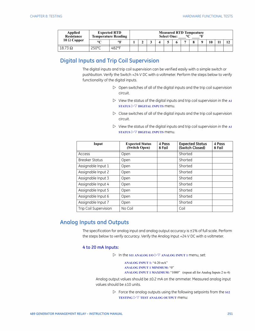
CHAPTER 8: TESTING HARDWARE FUNCTIONAL TESTS
489 GENERATOR MANAGEMENT RELAY – INSTRUCTION MANUAL 251
Digital Inputs and Trip Coil SupervisionThe digital inputs and trip coil supervision can be verified easily with a simple switch or pushbutton. Verify the Switch +24 V DC with a voltmeter. Perform the steps below to verify functionality of the digital inputs.
Open switches of all of the digital inputs and the trip coil supervision circuit.
View the status of the digital inputs and trip coil supervision in the A1
STATUS DIGITAL INPUTS menu.
Close switches of all of the digital inputs and the trip coil supervision circuit.
View the status of the digital inputs and trip coil supervision in the A1
STATUS DIGITAL INPUTS menu.
Analog Inputs and OutputsThe specification for analog input and analog output accuracy is ±1% of full scale. Perform the steps below to verify accuracy. Verify the Analog Input +24 V DC with a voltmeter.
4 to 20 mA Inputs:
In the S11 ANALOG I/O ANALOG INPUT 1 menu, set:
ANALOG INPUT 1: “4-20 mA”
ANALOG INPUT 1 MINIMUM: “0”
ANALOG INPUT 1 MAXIMUM: “1000” (repeat all for Analog Inputs 2 to 4)
Analog output values should be ±0.2 mA on the ammeter. Measured analog input values should be ±10 units.
Force the analog outputs using the following setpoints from the S12
TESTING TEST ANALOG OUTPUT menu:
18.73 Ω 250°C 482°F
Applied Resistance
10 Ω Copper
Expected RTD Temperature Reading
Measured RTD TempeatureSelect One: ____°C ____°F
°C °F 1 2 3 4 5 6 7 8 9 10 11 12
Input Expected Status (Switch Open)
4 Pass8 Fail
Expected Status (Switch Closed)
4 Pass8 Fail
Access Open Shorted
Breaker Status Open Shorted
Assignable Input 1 Open Shorted
Assignable Input 2 Open Shorted
Assignable Input 3 Open Shorted
Assignable Input 4 Open Shorted
Assignable Input 5 Open Shorted
Assignable Input 6 Open Shorted
Assignable Input 7 Open Shorted
Trip Coil Supervision No Coil Coil
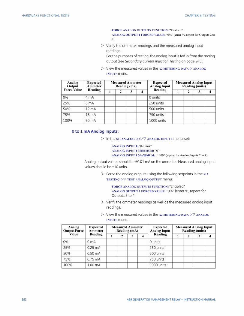
252 489 GENERATOR MANAGEMENT RELAY – INSTRUCTION MANUAL
HARDWARE FUNCTIONAL TESTS CHAPTER 8: TESTING
FORCE ANALOG OUTPUTS FUNCTION: “Enabled”
ANALOG OUTPUT 1 FORCED VALUE: “0%” (enter %, repeat for Outputs 2 to
4)
Verify the ammeter readings and the measured analog input readings. For the purposes of testing, the analog input is fed in from the analog output (see Secondary Current Injection Testing on page 245).
View the measured values in the A2 METERING DATA ANALOG
INPUTS menu.
0 to 1 mA Analog Inputs:
In the S11 ANALOG I/O ANALOG INPUT 1 menu, set:
ANALOG INPUT 1: “0-1 mA”
ANALOG INPUT 1 MINIMUM: “0”
ANALOG INPUT 1 MAXIMUM: “1000” (repeat for Analog Inputs 2 to 4)
Analog output values should be ±0.01 mA on the ammeter. Measured analog input values should be ±10 units.
Force the analog outputs using the following setpoints in the S12
TESTING TEST ANALOG OUTPUT menu:
FORCE ANALOG OUTPUTS FUNCTION: “Enabled”ANALOG OUTPUT 1 FORCED VALUE: “0%” (enter %, repeat for Outputs 2 to 4)
Verify the ammeter readings as well as the measured analog input readings.
View the measured values in the A2 METERING DATA ANALOG
INPUTS menu.
Analog Output
Force Value
Expected Ammeter Reading
Measured Ammeter Reading (ma)
Expected Analog Input
Reading
Measured Analog Input Reading (units)
1 2 3 4 1 2 3 4
0% 4 mA 0 units
25% 8 mA 250 units
50% 12 mA 500 units
75% 16 mA 750 units
100% 20 mA 1000 units
Analog Output Force
Value
Expected Ammeter Reading
Measured Ammeter Reading (mA)
Expected Analog Input
Reading
Measured Analog Input Reading (units)
1 2 3 4 1 2 3 4
0% 0 mA 0 units
25% 0.25 mA 250 units
50% 0.50 mA 500 units
75% 0.75 mA 750 units
100% 1.00 mA 1000 units
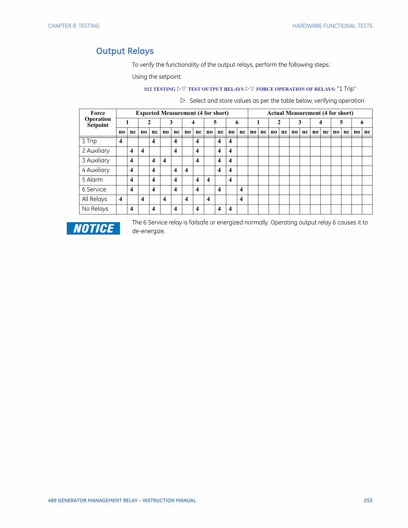
CHAPTER 8: TESTING HARDWARE FUNCTIONAL TESTS
489 GENERATOR MANAGEMENT RELAY – INSTRUCTION MANUAL 253
Output RelaysTo verify the functionality of the output relays, perform the following steps:
Using the setpoint:
S12 TESTING TEST OUTPUT RELAYS FORCE OPERATION OF RELAYS: “1 Trip”
Select and store values as per the table below, verifying operation
The 6 Service relay is failsafe or energized normally. Operating output relay 6 causes it to de-energize.
Force Operation Setpoint
Expected Measurement (4 for short) Actual Measurement (4 for short)
1 2 3 4 5 6 1 2 3 4 5 6
no nc no nc no nc no nc no nc no nc no nc no nc no nc no nc no nc no nc
1 Trip 4 4 4 4 4 4
2 Auxiliary 4 4 4 4 4 4
3 Auxiliary 4 4 4 4 4 4
4 Auxiliary 4 4 4 4 4 4
5 Alarm 4 4 4 4 4 4
6 Service 4 4 4 4 4 4
All Relays 4 4 4 4 4 4
No Relays 4 4 4 4 4 4
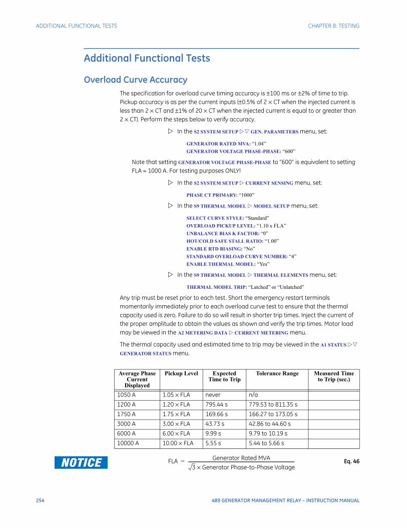
254 489 GENERATOR MANAGEMENT RELAY – INSTRUCTION MANUAL
ADDITIONAL FUNCTIONAL TESTS CHAPTER 8: TESTING
Additional Functional Tests
Overload Curve AccuracyThe specification for overload curve timing accuracy is ±100 ms or ±2% of time to trip. Pickup accuracy is as per the current inputs (±0.5% of 2 × CT when the injected current is less than 2 × CT and ±1% of 20 × CT when the injected current is equal to or greater than 2 × CT). Perform the steps below to verify accuracy.
In the S2 SYSTEM SETUP GEN. PARAMETERS menu, set:
GENERATOR RATED MVA: “1.04”
GENERATOR VOLTAGE PHASE-PHASE: “600”
Note that setting GENERATOR VOLTAGE PHASE-PHASE to “600” is equivalent to setting FLA = 1000 A. For testing purposes ONLY!
In the S2 SYSTEM SETUP CURRENT SENSING menu, set:
PHASE CT PRIMARY: “1000”
In the S9 THERMAL MODEL MODEL SETUP menu, set:
SELECT CURVE STYLE: “Standard”
OVERLOAD PICKUP LEVEL: “1.10 x FLA”
UNBALANCE BIAS K FACTOR: “0”
HOT/COLD SAFE STALL RATIO: “1.00”
ENABLE RTD BIASING: “No”
STANDARD OVERLOAD CURVE NUMBER: “4”
ENABLE THERMAL MODEL: “Yes”
In the S9 THERMAL MODEL THERMAL ELEMENTS menu, set:
THERMAL MODEL TRIP: “Latched” or “Unlatched”
Any trip must be reset prior to each test. Short the emergency restart terminals momentarily immediately prior to each overload curve test to ensure that the thermal capacity used is zero. Failure to do so will result in shorter trip times. Inject the current of the proper amplitude to obtain the values as shown and verify the trip times. Motor load may be viewed in the A2 METERING DATA CURRENT METERING menu.
The thermal capacity used and estimated time to trip may be viewed in the A1 STATUS
GENERATOR STATUS menu.
Eq. 46
Average Phase Current
Displayed
Pickup Level Expected Time to Trip
Tolerance Range Measured Time to Trip (sec.)
1050 A 1.05 × FLA never n/a
1200 A 1.20 × FLA 795.44 s 779.53 to 811.35 s
1750 A 1.75 × FLA 169.66 s 166.27 to 173.05 s
3000 A 3.00 × FLA 43.73 s 42.86 to 44.60 s
6000 A 6.00 × FLA 9.99 s 9.79 to 10.19 s
10000 A 10.00 × FLA 5.55 s 5.44 to 5.66 s
FLA Generator Rated MVA
3 Generator Phase-to-Phase Voltage×-----------------------------------------------------------------------------------------------------=

CHAPTER 8: TESTING ADDITIONAL FUNCTIONAL TESTS
489 GENERATOR MANAGEMENT RELAY – INSTRUCTION MANUAL 255
Power Measurement TestThe specification for reactive and apparent power is ± 1% of × 2 × CT × VTratio × VTfull-
scale at Iavg < 2 × CT. Perform the steps below to verify accuracy.
In the S2 SYSTEM SETUP CURRENT SENSING menu, set:
PHASE CT PRIMARY: “1000”
In the S2 SYSTEM SETUP VOLTAGE SENSING menu, set:
VT CONNECTION TYPE: “Wye”
VOLTAGE TRANSFORMER RATIO: “10.00:1”
Inject current and apply voltage as per the table below.
Verify accuracy of the measured values.
View the measured values in the A2 METERING DATA POWER
METERING menu:
Reactive Power AccuracyThe specification for reactive power is ±1% of × 2 × CT × VTratio × VTfull scale at Iavg < 2 × CT. Perform the steps below to verify accuracy and trip element.
In the S2 SYSTEM SETUP CURRENT SENSING menu, set:
PHASE CT PRIMARY: “5000”
In the S2 SYSTEM SETUP VOLTAGE SENSING menu, set:
VT CONNECTION TYPE: “Wye”
VOLTAGE TRANSFORMER RATIO: “100:1”
In the S2 SYSTEM SETUP GEN. PARAMETERS menu, set
GENERATOR RATED MVA: “100”
GENERATOR RATED POWER FACTOR: “0.85”
GENERATOR VOLTAGE PHASE-PHASE: “12000”
The rated reactive power is .
Alter the following reactive power setpoints in the S7 POWER
ELEMENTS REACTIVE POWER menu:
3
Injected Current / Applied Voltage(Ia is the reference vector)
Power Quantity Power Factor
1 A UNIT 5 A UNIT Expected Tolerance Measured Expected Measured
Ia = 1 A∠0°Ib = 1 A∠120° lagIc = 1 A∠240° lagVa = 120 V∠342° lagVb = 120 V∠102° lagVc = 120 V∠222° lag
Ia = 5 A∠0°Ib = 5 A∠120° lagIc = 5 A∠240° lagIa = 120 V∠342° lagVb = 120 V∠102° lagVc = 120 V∠222° lag
+3424 kW 3355 to 3493 kW 0.95 lag
Ia = 1 A∠0°Ib = 1 A∠120° lagIc = 1 A∠240° lagVa = 120 V∠288° lagVb = 120 V∠48° lagVc = 120 V∠168° lag
Ia = 5 A∠0°Ib = 5 A∠120° lagIc = 5 A∠240° lagVa = 120 V∠288° lagVb = 120 V∠48° lagVc = 120 V∠168° lag
+3424 kvar 3355 to 3493 kvar 0.31 lag
3
100 cos 1– 0.85( )( )sin 52.7 Mvar±=
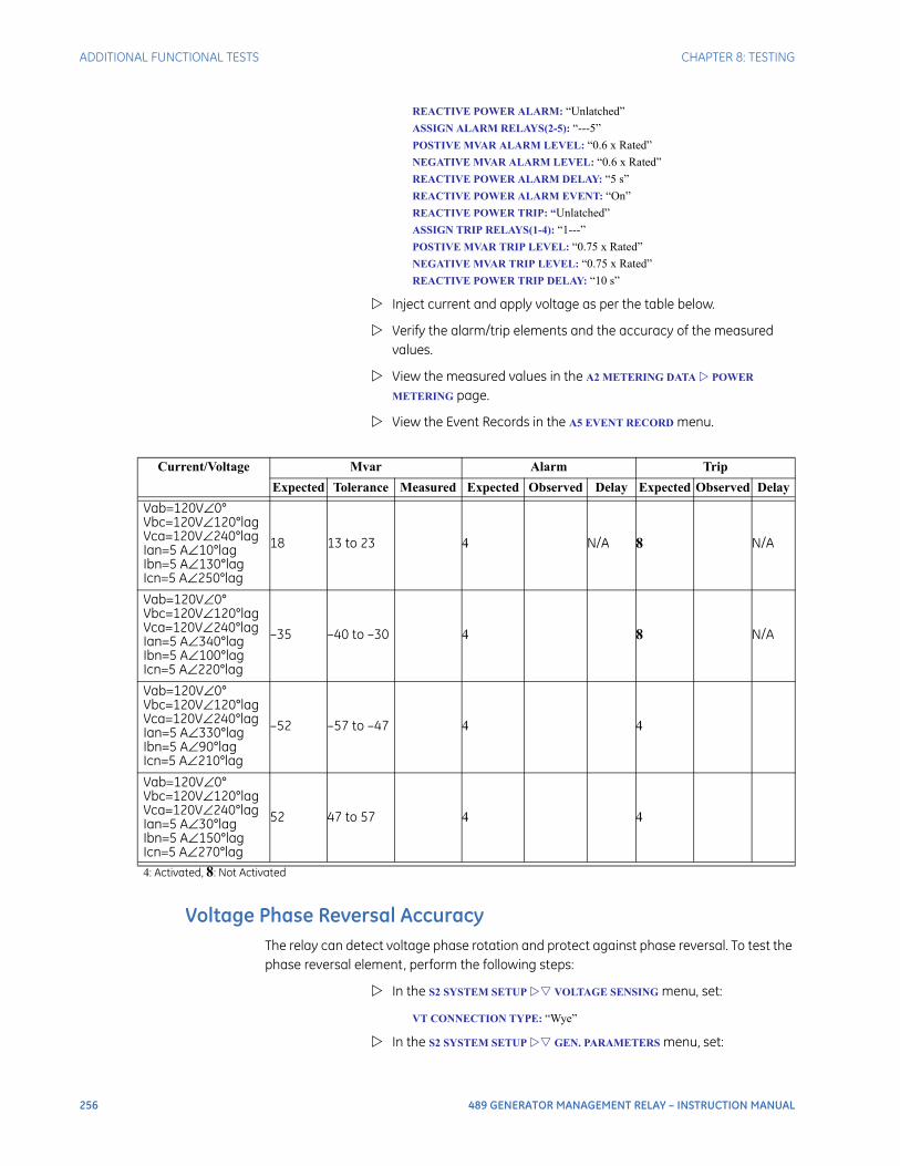
256 489 GENERATOR MANAGEMENT RELAY – INSTRUCTION MANUAL
ADDITIONAL FUNCTIONAL TESTS CHAPTER 8: TESTING
REACTIVE POWER ALARM: “Unlatched”
ASSIGN ALARM RELAYS(2-5): “---5”
POSTIVE MVAR ALARM LEVEL: “0.6 x Rated”
NEGATIVE MVAR ALARM LEVEL: “0.6 x Rated”
REACTIVE POWER ALARM DELAY: “5 s”
REACTIVE POWER ALARM EVENT: “On”
REACTIVE POWER TRIP: “Unlatched”
ASSIGN TRIP RELAYS(1-4): “1---”
POSTIVE MVAR TRIP LEVEL: “0.75 x Rated”
NEGATIVE MVAR TRIP LEVEL: “0.75 x Rated”
REACTIVE POWER TRIP DELAY: “10 s”
Inject current and apply voltage as per the table below.
Verify the alarm/trip elements and the accuracy of the measured values.
View the measured values in the A2 METERING DATA POWER
METERING page.
View the Event Records in the A5 EVENT RECORD menu.
Voltage Phase Reversal AccuracyThe relay can detect voltage phase rotation and protect against phase reversal. To test the phase reversal element, perform the following steps:
In the S2 SYSTEM SETUP VOLTAGE SENSING menu, set:
VT CONNECTION TYPE: “Wye”
In the S2 SYSTEM SETUP GEN. PARAMETERS menu, set:
Current/Voltage Mvar Alarm Trip
Expected Tolerance Measured Expected Observed Delay Expected Observed Delay
Vab=120V∠0°Vbc=120V∠120°lagVca=120V∠240°lagIan=5 A∠10°lagIbn=5 A∠130°lagIcn=5 A∠250°lag
18 13 to 23 4 N/A 8 N/A
Vab=120V∠0°Vbc=120V∠120°lagVca=120V∠240°lagIan=5 A∠340°lagIbn=5 A∠100°lagIcn=5 A∠220°lag
–35 –40 to –30 4 8 N/A
Vab=120V∠0°Vbc=120V∠120°lagVca=120V∠240°lagIan=5 A∠330°lagIbn=5 A∠90°lagIcn=5 A∠210°lag
–52 –57 to –47 4 4
Vab=120V∠0°Vbc=120V∠120°lagVca=120V∠240°lagIan=5 A∠30°lagIbn=5 A∠150°lagIcn=5 A∠270°lag
52 47 to 57 4 4
4: Activated, 8: Not Activated
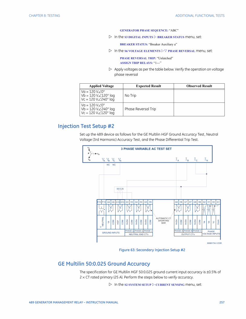
CHAPTER 8: TESTING ADDITIONAL FUNCTIONAL TESTS
489 GENERATOR MANAGEMENT RELAY – INSTRUCTION MANUAL 257
GENERATOR PHASE SEQUENCE: “ABC”
In the S3 DIGITAL INPUTS BREAKER STATUS menu, set:
BREAKER STATUS: “Breaker Auxiliary a”
In the S6 VOLTAGE ELEMENTS PHASE REVERSAL menu, set:
PHASE REVERSAL TRIP: “Unlatched”
ASSIGN TRIP RELAYS: “1---”
Apply voltages as per the table below. Verify the operation on voltage phase reversal
Injection Test Setup #2Set up the 489 device as follows for the GE Multilin HGF Ground Accuracy Test, Neutral Voltage (3rd Harmonic) Accuracy Test, and the Phase Differential Trip Test.
Figure 63: Secondary Injection Setup #2
GE Multilin 50:0.025 Ground AccuracyThe specification for GE Multilin HGF 50:0.025 ground current input accuracy is ±0.5% of 2 × CT rated primary (25 A). Perform the steps below to verify accuracy.
In the S2 SYSTEM SETUP CURRENT SENSING menu, set:
Applied Voltage Expected Result Observed Result
Va = 120 V∠0°Vb = 120 V∠120° lagVc = 120 V∠240° lag
No Trip
Va = 120 V∠0°Vb = 120 V∠240° lagVc = 120 V∠120° lag
Phase Reversal Trip
E10
V
NE
UT
RA
L
1A
HG
F
1A
/5A
1A
/5A
1A
/5A
1A
/5A
1A
/5A
1A
/5A
CO
M
CO
M
CO
M
CO
M
CO
M
PHASE a PHASE b PHASE c PHASE A PHASE B PHASE C
CO
M
CO
M
CO
M
Va
Vb
Vco
m
Vc
H9 G3 G6H4 H7 H1F10
A B C N A B C NV V V V I I I I
3 PHASE VARIABLE AC TEST SET
GROUND INPUTSNEUTRAL END CT's OUTPUT CT's
PHASE
VOLTAGE INPUTS
G10 H3 H6G5 G8 H2
808817A1.CDR
G9
50:0.25
NC NC
H10 G4 G7 G2H5 H8 G1
AUTOMATIC CT
SHORTING
BAR
VC
VA
VB
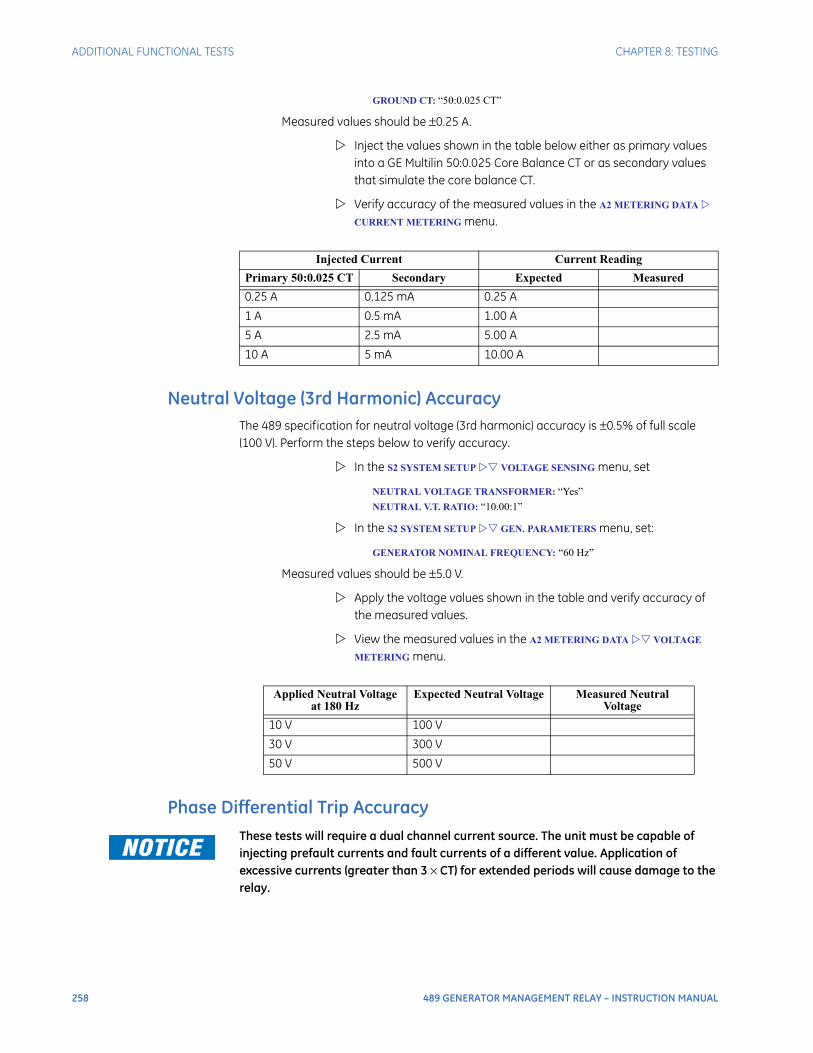
258 489 GENERATOR MANAGEMENT RELAY – INSTRUCTION MANUAL
ADDITIONAL FUNCTIONAL TESTS CHAPTER 8: TESTING
GROUND CT: “50:0.025 CT”
Measured values should be ±0.25 A.
Inject the values shown in the table below either as primary values into a GE Multilin 50:0.025 Core Balance CT or as secondary values that simulate the core balance CT.
Verify accuracy of the measured values in the A2 METERING DATA
CURRENT METERING menu.
Neutral Voltage (3rd Harmonic) AccuracyThe 489 specification for neutral voltage (3rd harmonic) accuracy is ±0.5% of full scale (100 V). Perform the steps below to verify accuracy.
In the S2 SYSTEM SETUP VOLTAGE SENSING menu, set
NEUTRAL VOLTAGE TRANSFORMER: “Yes”
NEUTRAL V.T. RATIO: “10.00:1”
In the S2 SYSTEM SETUP GEN. PARAMETERS menu, set:
GENERATOR NOMINAL FREQUENCY: “60 Hz”
Measured values should be ±5.0 V.
Apply the voltage values shown in the table and verify accuracy of the measured values.
View the measured values in the A2 METERING DATA VOLTAGE
METERING menu.
Phase Differential Trip AccuracyThese tests will require a dual channel current source. The unit must be capable of injecting prefault currents and fault currents of a different value. Application of excessive currents (greater than 3 × CT) for extended periods will cause damage to the relay.
Injected Current Current Reading
Primary 50:0.025 CT Secondary Expected Measured
0.25 A 0.125 mA 0.25 A
1 A 0.5 mA 1.00 A
5 A 2.5 mA 5.00 A
10 A 5 mA 10.00 A
Applied Neutral Voltage at 180 Hz
Expected Neutral Voltage Measured Neutral Voltage
10 V 100 V
30 V 300 V
50 V 500 V
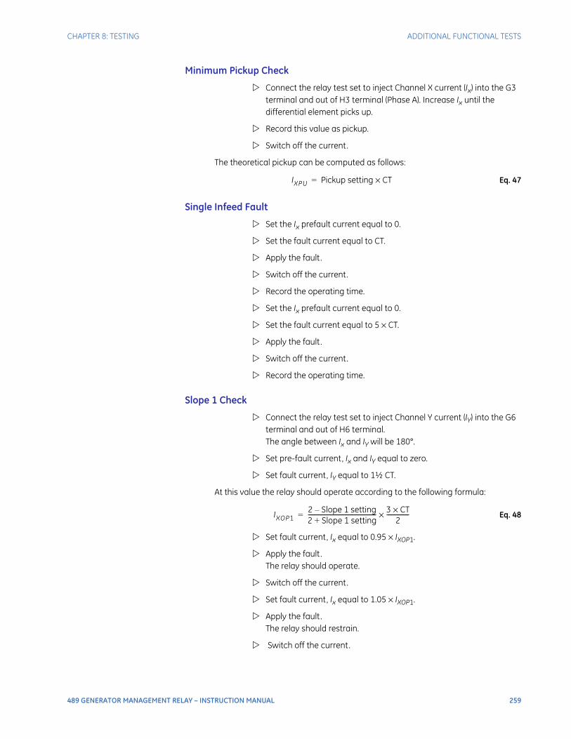
CHAPTER 8: TESTING ADDITIONAL FUNCTIONAL TESTS
489 GENERATOR MANAGEMENT RELAY – INSTRUCTION MANUAL 259
Minimum Pickup Check
Connect the relay test set to inject Channel X current (Ix) into the G3 terminal and out of H3 terminal (Phase A). Increase Ix until the differential element picks up.
Record this value as pickup.
Switch off the current.
The theoretical pickup can be computed as follows:
Eq. 47
Single Infeed Fault
Set the Ix prefault current equal to 0.
Set the fault current equal to CT.
Apply the fault.
Switch off the current.
Record the operating time.
Set the Ix prefault current equal to 0.
Set the fault current equal to 5 × CT.
Apply the fault.
Switch off the current.
Record the operating time.
Slope 1 Check
Connect the relay test set to inject Channel Y current (IY) into the G6 terminal and out of H6 terminal. The angle between Ix and IY will be 180°.
Set pre-fault current, Ix and IY equal to zero.
Set fault current, IY equal to 1½ CT.
At this value the relay should operate according to the following formula:
Eq. 48
Set fault current, Ix equal to 0.95 × IXOP1.
Apply the fault. The relay should operate.
Switch off the current.
Set fault current, Ix equal to 1.05 × IXOP1.
Apply the fault. The relay should restrain.
Switch off the current.
IXPU Pickup setting CT×=
IXOP12 Slope 1 setting–2 Slope 1 setting+---------------------------------------------- 3 CT×
2---------------×=
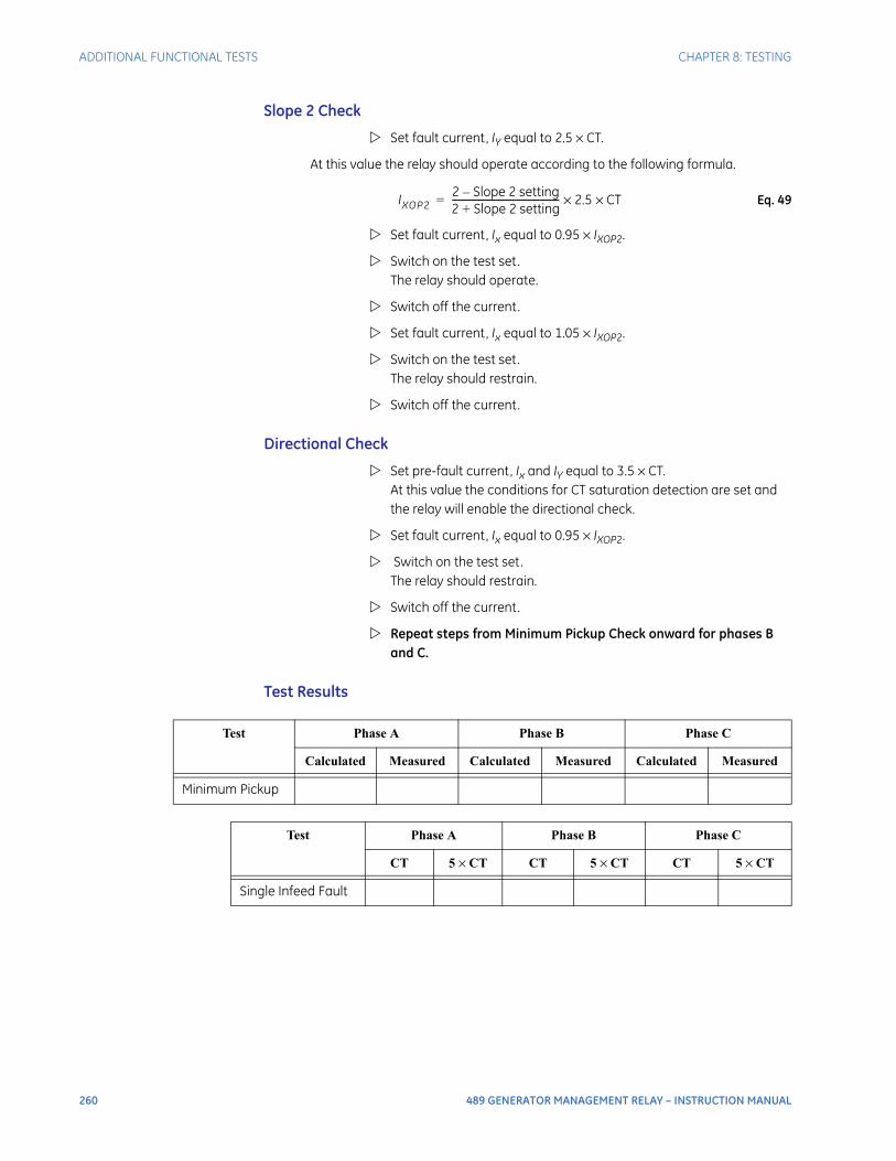
260 489 GENERATOR MANAGEMENT RELAY – INSTRUCTION MANUAL
ADDITIONAL FUNCTIONAL TESTS CHAPTER 8: TESTING
Slope 2 Check
Set fault current, IY equal to 2.5 × CT.
At this value the relay should operate according to the following formula.
Eq. 49
Set fault current, Ix equal to 0.95 × IXOP2.
Switch on the test set. The relay should operate.
Switch off the current.
Set fault current, Ix equal to 1.05 × IXOP2.
Switch on the test set. The relay should restrain.
Switch off the current.
Directional Check
Set pre-fault current, Ix and IY equal to 3.5 × CT. At this value the conditions for CT saturation detection are set and the relay will enable the directional check.
Set fault current, Ix equal to 0.95 × IXOP2.
Switch on the test set. The relay should restrain.
Switch off the current.
Repeat steps from Minimum Pickup Check onward for phases B and C.
Test Results
IXOP22 Slope 2 setting–2 Slope 2 setting+---------------------------------------------- 2.5 CT××=
Test Phase A Phase B Phase C
Calculated Measured Calculated Measured Calculated Measured
Minimum Pickup
Test Phase A Phase B Phase C
CT 5 × CT CT 5 × CT CT 5 × CT
Single Infeed Fault
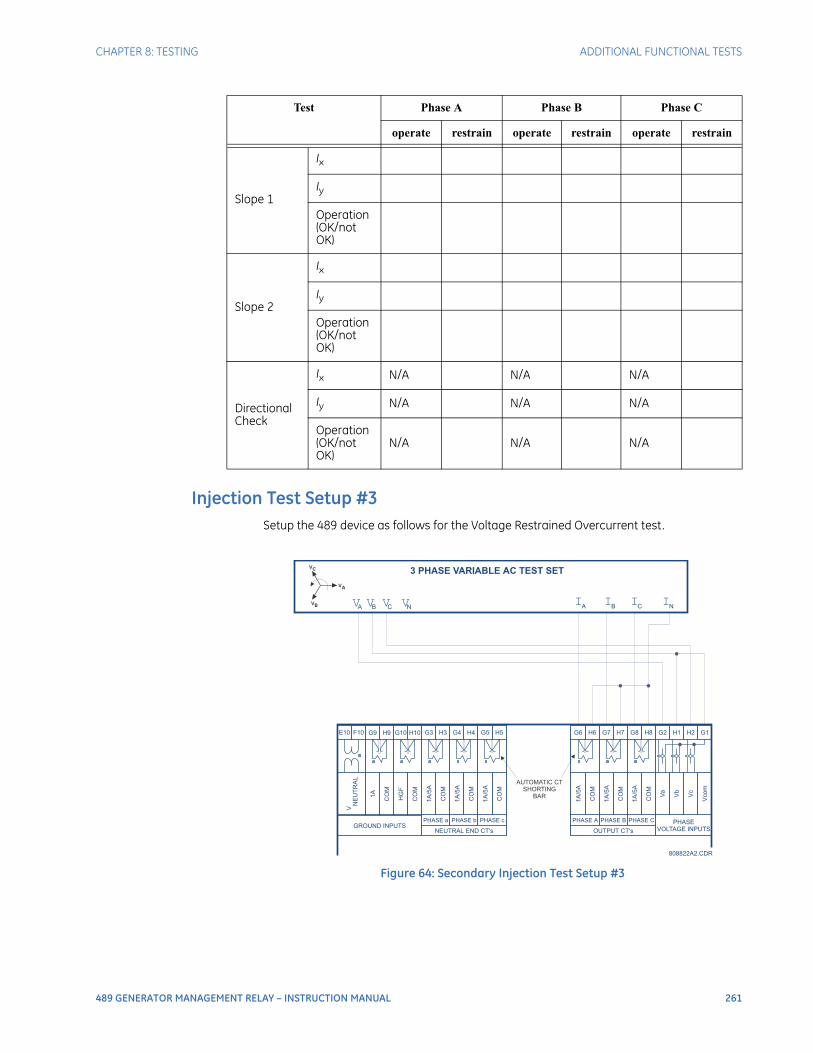
CHAPTER 8: TESTING ADDITIONAL FUNCTIONAL TESTS
489 GENERATOR MANAGEMENT RELAY – INSTRUCTION MANUAL 261
Injection Test Setup #3Setup the 489 device as follows for the Voltage Restrained Overcurrent test.
Figure 64: Secondary Injection Test Setup #3
Test Phase A Phase B Phase C
operate restrain operate restrain operate restrain
Slope 1
Ix
Iy
Operation (OK/not OK)
Slope 2
Ix
Iy
Operation (OK/not OK)
Directional Check
Ix N/A N/A N/A
Iy N/A N/A N/A
Operation (OK/not OK)
N/A N/A N/A
E10
V
NE
UT
RA
L
1A
HG
F
1A
/5A
1A
/5A
1A
/5A
1A
/5A
1A
/5A
1A
/5A
CO
M
CO
M
CO
M
CO
M
CO
M
PHASE a PHASE b PHASE c PHASE A PHASE B PHASE C
CO
M
CO
M
CO
M
Va
Vb
Vco
m
Vc
H9 G3 G6H4 H7 H1F10
A B C N A B C NV V V V I I I I
3 PHASE VARIABLE AC TEST SET
GROUND INPUTSNEUTRAL END CT's OUTPUT CT's
808822A2.CDR
PHASE
VOLTAGE INPUTS
G10 H3 H6G5 G8 H2G9 H10 G4 G7 G2H5 H8 G1
AUTOMATIC CT
SHORTING
BAR
VC
VA
VB
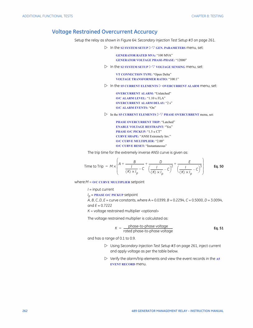
262 489 GENERATOR MANAGEMENT RELAY – INSTRUCTION MANUAL
ADDITIONAL FUNCTIONAL TESTS CHAPTER 8: TESTING
Voltage Restrained Overcurrent AccuracySetup the relay as shown in Figure 64: Secondary Injection Test Setup #3 on page 261.
In the S2 SYSTEM SETUP GEN. PARAMETERS menu, set:
GENERATOR RATED MVA: “100 MVA”
GENERATOR VOLTAGE PHASE-PHASE: “12000”
In the S2 SYSTEM SETUP VOLTAGE SENSING menu, set:
VT CONNECTION TYPE: “Open Delta”
VOLTAGE TRANSFORMER RATIO: “100:1”
In the S5 CURRENT ELEMENTS OVERCURRENT ALARM menu, set:
OVERCURRENT ALARM: “Unlatched”
O/C ALARM LEVEL: “1.10 x FLA”
OVERCURRENT ALARM DELAY: “2 s”
O/C ALARM EVENTS: “On”
In the S5 CURRENT ELEMENTS PHASE OVERCURRENT menu, set:
PHASE OVERCURRENT TRIP: “Latched”
ENABLE VOLTAGE RESTRAINT: “Yes”
PHASE O/C PICKUP: “1.5 x CT”
CURVE SHAPE: “ANSI Extremely Inv.”
O/C CURVE MULTIPLIER: “2.00”
O/C CURVE RESET: “Instantaneous”
The trip time for the extremely inverse ANSI curve is given as:
Eq. 50
where:M = O/C CURVE MULTIPLIER setpoint
I = input currentIp = PHASE O/C PICKUP setpointA, B, C, D, E = curve constants, where A = 0.0399, B = 0.2294, C = 0.5000, D = 3.0094, and E = 0.7222K = voltage restrained multiplier <optional>
The voltage restrained multiplier is calculated as:
Eq. 51
and has a range of 0.1 to 0.9.
Using Secondary Injection Test Setup #3 on page 261, inject current and apply voltage as per the table below.
Verify the alarm/trip elements and view the event records in the A5
EVENT RECORD menu.
Time to Trip MA B
IK Ip×
------------------- C–----------------------------- D
IK Ip×
------------------- C– 2------------------------------------- E
IK Ip×
------------------- C– 3-------------------------------------+ + +
×=
K phase-to-phase voltagerated phase-to-phase voltage---------------------------------------------------------------------------=
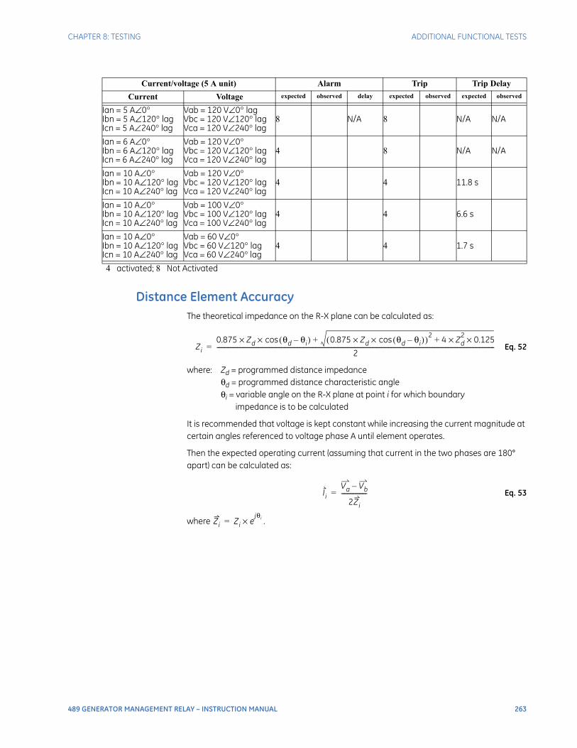
CHAPTER 8: TESTING ADDITIONAL FUNCTIONAL TESTS
489 GENERATOR MANAGEMENT RELAY – INSTRUCTION MANUAL 263
Distance Element AccuracyThe theoretical impedance on the R-X plane can be calculated as:
Eq. 52
where: Zd = programmed distance impedanceθd = programmed distance characteristic angleθi = variable angle on the R-X plane at point i for which boundary
impedance is to be calculated
It is recommended that voltage is kept constant while increasing the current magnitude at certain angles referenced to voltage phase A until element operates.
Then the expected operating current (assuming that current in the two phases are 180° apart) can be calculated as:
Eq. 53
where .
Current/voltage (5 A unit) Alarm Trip Trip Delay
Current Voltage expected observed delay expected observed expected observed
Ian = 5 A∠0°Ibn = 5 A∠120° lagIcn = 5 A∠240° lag
Vab = 120 V∠0° lagVbc = 120 V∠120° lagVca = 120 V∠240° lag
8 N/A 8 N/A N/A
Ian = 6 A∠0°Ibn = 6 A∠120° lagIcn = 6 A∠240° lag
Vab = 120 V∠0°Vbc = 120 V∠120° lagVca = 120 V∠240° lag
4 8 N/A N/A
Ian = 10 A∠0°Ibn = 10 A∠120° lagIcn = 10 A∠240° lag
Vab = 120 V∠0°Vbc = 120 V∠120° lagVca = 120 V∠240° lag
4 4 11.8 s
Ian = 10 A∠0°Ibn = 10 A∠120° lagIcn = 10 A∠240° lag
Vab = 100 V∠0°Vbc = 100 V∠120° lagVca = 100 V∠240° lag
4 4 6.6 s
Ian = 10 A∠0°Ibn = 10 A∠120° lagIcn = 10 A∠240° lag
Vab = 60 V∠0°Vbc = 60 V∠120° lagVca = 60 V∠240° lag
4 4 1.7 s
4 activated; 8 Not Activated
Zi0.875 Zd θd θi–( )cos×× 0.875 Zd θd θi–( )cos××( )2 4 Zd
2 0.125××++
2------------------------------------------------------------------------------------------------------------------------------------------------------------------------------------------=
IiVa Vb–
2Zi
-----------------=
Zi Zi ejθi×=

264 489 GENERATOR MANAGEMENT RELAY – INSTRUCTION MANUAL
ADDITIONAL FUNCTIONAL TESTS CHAPTER 8: TESTING
489 GENERATOR MANAGEMENT RELAY – INSTRUCTION MANUAL 265
489 Generator Management Relay
Chapter 9: Appendix
Appendix
Stator Ground Fault
DescriptionThis application note describes general protection concepts and provides guidelines on the use of the 489 to protect a generator stator against ground faults. Detailed connections for specific features must be obtained from the relay manual. Users are also urged to review the material contained in the 489 manual on each specific protection feature discussed here.
The 489 Generator Management Relay offers a number of elements to protect a generator against stator ground faults. Inputs are provided for a neutral-point voltage signal and for a zero-sequence current signal. The zero-sequence current input can be into a nominal 1 A secondary circuit or an input reserved for a special GE Multilin type HGF ground CT for very sensitive ground current detection. Using the HGF CT allows measurement of ground current values as low as 0.25 A primary. With impedance-grounded generators, a single ground fault on the stator does not require that the unit be quickly removed from service. The grounding impedance limits the fault current to a few amperes. A second ground fault can, however, result in significant damage to the unit. Thus the importance of detecting all ground faults, even those in the bottom 5% of the stator. The fault detection methods depend on the grounding arrangement, the availability of core balance CT, and the size of the unit. With modern full-featured digital generator protection relays such as the 489, users do not incur additional costs for extra protection elements as they are all part of the same device. This application note provides general descriptions of each of the elements in the 489 suitable for stator ground protection, and discusses some special applications.

266 489 GENERATOR MANAGEMENT RELAY – INSTRUCTION MANUAL
STATOR GROUND FAULT CHAPTER 9: APPENDIX
Neutral Overvoltage ElementThe simplest, and one of the oldest methods to detect stator ground faults on high-impedance-grounded generators, is to sense the voltage across the stator grounding resistor (See References [1, 2] at the end of this section). This is illustrated, in a simplified form in the figure below. The voltage signal is connected to the Vneutral input of the 489, terminals E10 and F10. The Vneutral signal is the input signal for the 489 neutral overvoltage protection element. This element has an alarm and a trip function, with separately adjustable operate levels and time delays. The trip function offers a choice of timing curves as well as a definite time delay. The neutral overvoltage function responds to fundamental frequency voltage at the generator neutral. It provides ground fault protection for approximately 95% of the stator winding. The limiting factor is the level of voltage signal available for a fault in the bottom 5% of the stator winding. The element has a range of adjustment, for the operate levels, of 2 to 100 V.
Figure 65: Stator Ground Fault Protection
The operating time of this element should be coordinated with protective elements downstream, such as feeder ground fault elements, since the neutral overvoltage element will respond to external ground faults if the generator is directly connected to a power grid, without the use of a delta-wye transformer.
In addition, the time delay should be coordinated with the ground directional element (discussed later), if it is enabled, by using a longer delay on the neutral overvoltage element than on the directional element.
It is recommended that an isolation transformer be used between the relay and the grounding impedance to reduce common mode voltage problems, particularly on installations requiring long leads between the relay and the grounding impedance.
When several small generators are operated in parallel with a single step-up transformer, all generators may be grounded through the same impedance (the impedance normally consists of a distribution transformer and a properly sized resistor). It is possible that only one generator is grounded while the others have a floating neutral point when connected to the power grid (see the figure below). This operating mode is often adopted to prevent circulation of third-harmonic currents through the generators, if the installation is such that all the star points would end up connected together ahead of the common grounding impedance (if each generator has its own grounding impedance, the magnitude of the
808739A1.CDR
Generator
R is selected for a
maximum fault current
of 10 A, typically.
Overvoltage
RelayR
Distribution
Transformer
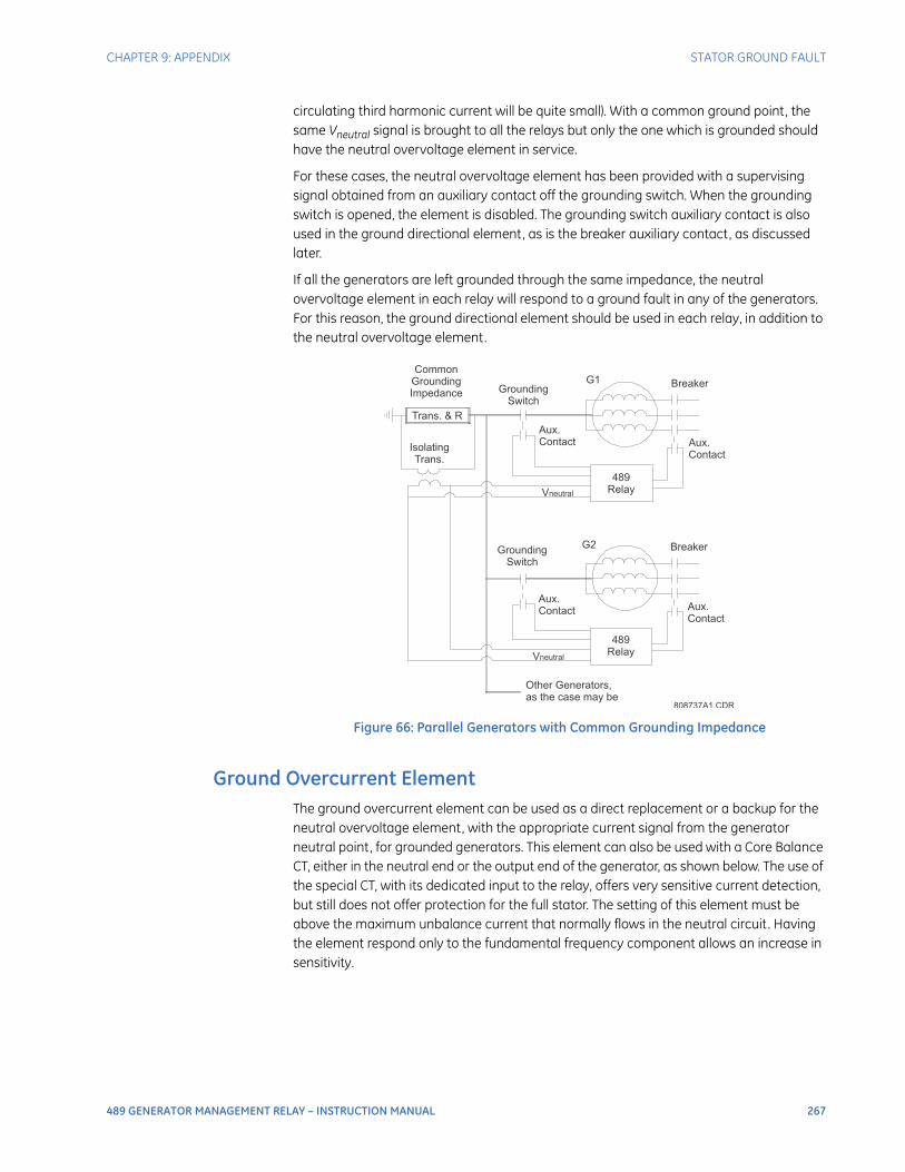
CHAPTER 9: APPENDIX STATOR GROUND FAULT
489 GENERATOR MANAGEMENT RELAY – INSTRUCTION MANUAL 267
circulating third harmonic current will be quite small). With a common ground point, the same Vneutral signal is brought to all the relays but only the one which is grounded should have the neutral overvoltage element in service.
For these cases, the neutral overvoltage element has been provided with a supervising signal obtained from an auxiliary contact off the grounding switch. When the grounding switch is opened, the element is disabled. The grounding switch auxiliary contact is also used in the ground directional element, as is the breaker auxiliary contact, as discussed later.
If all the generators are left grounded through the same impedance, the neutral overvoltage element in each relay will respond to a ground fault in any of the generators. For this reason, the ground directional element should be used in each relay, in addition to the neutral overvoltage element.
Figure 66: Parallel Generators with Common Grounding Impedance
Ground Overcurrent ElementThe ground overcurrent element can be used as a direct replacement or a backup for the neutral overvoltage element, with the appropriate current signal from the generator neutral point, for grounded generators. This element can also be used with a Core Balance CT, either in the neutral end or the output end of the generator, as shown below. The use of the special CT, with its dedicated input to the relay, offers very sensitive current detection, but still does not offer protection for the full stator. The setting of this element must be above the maximum unbalance current that normally flows in the neutral circuit. Having the element respond only to the fundamental frequency component allows an increase in sensitivity.
808737A1.CDR
Other Generators,
as the case may be
489
RelayVneutral
Aux.
Contact
G2
Aux.
Contact
BreakerGrounding
Switch
Grounding
Switch
Trans. & R
Aux.
Contact
Vneutral
G1
Common
Grounding
Impedance
Isolating
Trans.
489
Relay
Breaker
Aux.
Contact
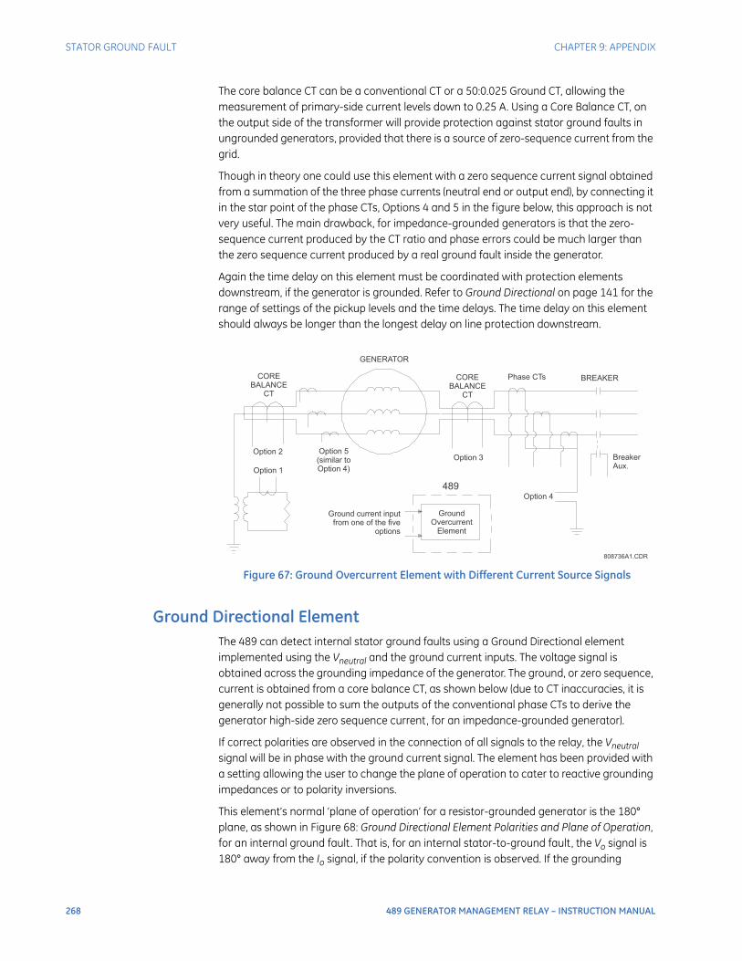
268 489 GENERATOR MANAGEMENT RELAY – INSTRUCTION MANUAL
STATOR GROUND FAULT CHAPTER 9: APPENDIX
The core balance CT can be a conventional CT or a 50:0.025 Ground CT, allowing the measurement of primary-side current levels down to 0.25 A. Using a Core Balance CT, on the output side of the transformer will provide protection against stator ground faults in ungrounded generators, provided that there is a source of zero-sequence current from the grid.
Though in theory one could use this element with a zero sequence current signal obtained from a summation of the three phase currents (neutral end or output end), by connecting it in the star point of the phase CTs, Options 4 and 5 in the figure below, this approach is not very useful. The main drawback, for impedance-grounded generators is that the zero-sequence current produced by the CT ratio and phase errors could be much larger than the zero sequence current produced by a real ground fault inside the generator.
Again the time delay on this element must be coordinated with protection elements downstream, if the generator is grounded. Refer to Ground Directional on page 141 for the range of settings of the pickup levels and the time delays. The time delay on this element should always be longer than the longest delay on line protection downstream.
Figure 67: Ground Overcurrent Element with Different Current Source Signals
Ground Directional ElementThe 489 can detect internal stator ground faults using a Ground Directional element implemented using the Vneutral and the ground current inputs. The voltage signal is obtained across the grounding impedance of the generator. The ground, or zero sequence, current is obtained from a core balance CT, as shown below (due to CT inaccuracies, it is generally not possible to sum the outputs of the conventional phase CTs to derive the generator high-side zero sequence current, for an impedance-grounded generator).
If correct polarities are observed in the connection of all signals to the relay, the Vneutral signal will be in phase with the ground current signal. The element has been provided with a setting allowing the user to change the plane of operation to cater to reactive grounding impedances or to polarity inversions.
This element’s normal ‘plane of operation’ for a resistor-grounded generator is the 180° plane, as shown in Figure 68: Ground Directional Element Polarities and Plane of Operation, for an internal ground fault. That is, for an internal stator-to-ground fault, the Vo signal is 180° away from the Io signal, if the polarity convention is observed. If the grounding
808736A1.CDR
489
GENERATOR
CORE
BALANCE
CT
CORE
BALANCE
CT
Phase CTs BREAKER
Breaker
Aux.
Option 2
Option 1
Option 5
(similar to
Option 4)
Option 3
Option 4
Ground
Overcurrent
Element
Ground current input
from one of the five
options
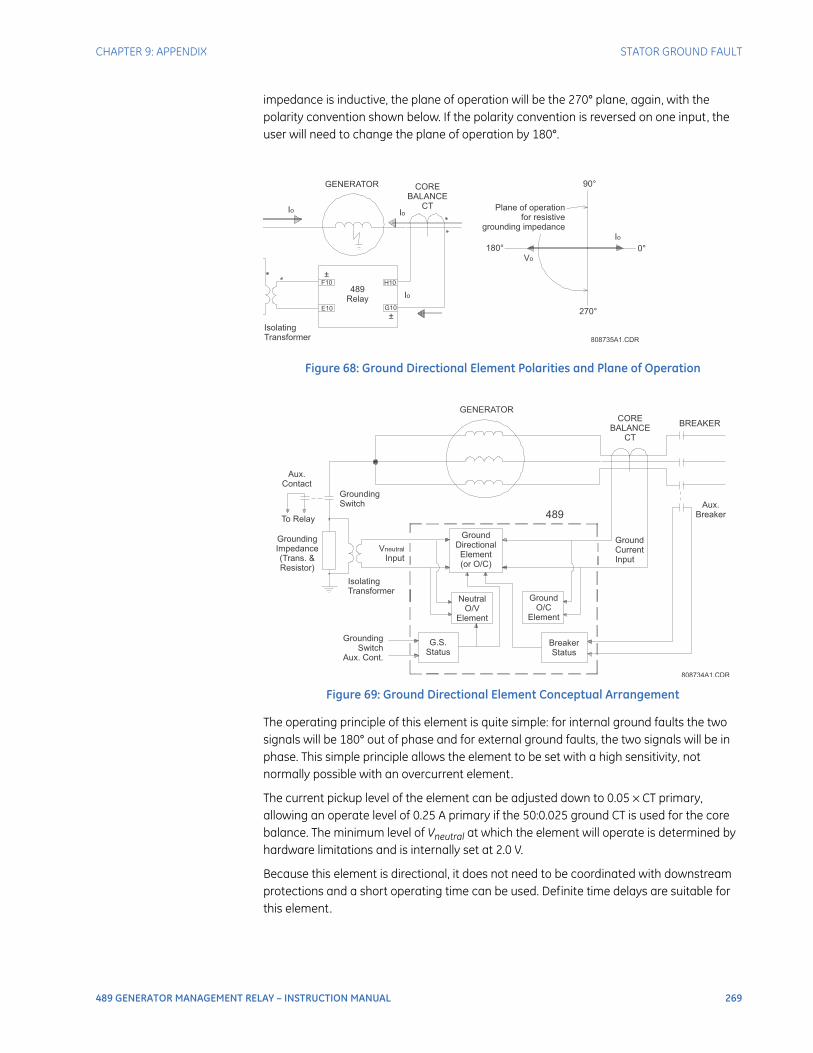
CHAPTER 9: APPENDIX STATOR GROUND FAULT
489 GENERATOR MANAGEMENT RELAY – INSTRUCTION MANUAL 269
impedance is inductive, the plane of operation will be the 270° plane, again, with the polarity convention shown below. If the polarity convention is reversed on one input, the user will need to change the plane of operation by 180°.
Figure 68: Ground Directional Element Polarities and Plane of Operation
Figure 69: Ground Directional Element Conceptual Arrangement
The operating principle of this element is quite simple: for internal ground faults the two signals will be 180° out of phase and for external ground faults, the two signals will be in phase. This simple principle allows the element to be set with a high sensitivity, not normally possible with an overcurrent element.
The current pickup level of the element can be adjusted down to 0.05 × CT primary, allowing an operate level of 0.25 A primary if the 50:0.025 ground CT is used for the core balance. The minimum level of Vneutral at which the element will operate is determined by hardware limitations and is internally set at 2.0 V.
Because this element is directional, it does not need to be coordinated with downstream protections and a short operating time can be used. Definite time delays are suitable for this element.
808735A1.CDR
GENERATOR
Io
CORE
BALANCE
CT Plane of operation
for resistive
grounding impedance
180°
270°
0°
90°
Isolating
Transformer
489
Relay
Vo
F10
E10
H10
G10
Io
Io
Io
±
±
808734A1.CDR
GENERATOR
CORE
BALANCE
CT
BREAKER
Aux.
Contact
Grounding
Switch
To Relay
Grounding
Impedance
(Trans. &
Resistor)
Grounding
Switch
Aux. Cont.
G.S.
Status
Breaker
Status
Ground
O/C
Element
Isolating
Transformer
V
Input
neutral
Ground
Directional
Element
(or O/C)
489
Neutral
O/V
Element
Ground
Current
Input
Aux.
Breaker
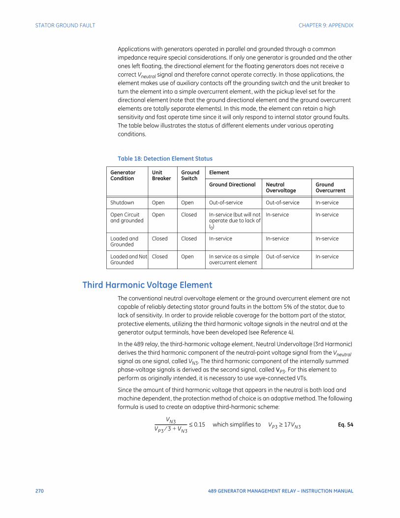
270 489 GENERATOR MANAGEMENT RELAY – INSTRUCTION MANUAL
STATOR GROUND FAULT CHAPTER 9: APPENDIX
Applications with generators operated in parallel and grounded through a common impedance require special considerations. If only one generator is grounded and the other ones left floating, the directional element for the floating generators does not receive a correct Vneutral signal and therefore cannot operate correctly. In those applications, the element makes use of auxiliary contacts off the grounding switch and the unit breaker to turn the element into a simple overcurrent element, with the pickup level set for the directional element (note that the ground directional element and the ground overcurrent elements are totally separate elements). In this mode, the element can retain a high sensitivity and fast operate time since it will only respond to internal stator ground faults. The table below illustrates the status of different elements under various operating conditions.
Third Harmonic Voltage ElementThe conventional neutral overvoltage element or the ground overcurrent element are not capable of reliably detecting stator ground faults in the bottom 5% of the stator, due to lack of sensitivity. In order to provide reliable coverage for the bottom part of the stator, protective elements, utilizing the third harmonic voltage signals in the neutral and at the generator output terminals, have been developed (see Reference 4).
In the 489 relay, the third-harmonic voltage element, Neutral Undervoltage (3rd Harmonic) derives the third harmonic component of the neutral-point voltage signal from the Vneutral signal as one signal, called VN3. The third harmonic component of the internally summed phase-voltage signals is derived as the second signal, called VP3. For this element to perform as originally intended, it is necessary to use wye-connected VTs.
Since the amount of third harmonic voltage that appears in the neutral is both load and machine dependent, the protection method of choice is an adaptive method. The following formula is used to create an adaptive third-harmonic scheme:
Eq. 54
Table 18: Detection Element Status
Generator Condition
Unit Breaker
Ground Switch
Element
Ground Directional Neutral Overvoltage
Ground Overcurrent
Shutdown Open Open Out-of-service Out-of-service In-service
Open Circuit and grounded
Open Closed In-service (but will not operate due to lack of I0)
In-service In-service
Loaded and Grounded
Closed Closed In-service In-service In-service
Loaded and Not Grounded
Closed Open In service as a simple overcurrent element
Out-of-service In-service
VN3
VP3 3⁄ VN3+------------------------------- 0.15 which simplifies to VP3 17VN3≥≤

CHAPTER 9: APPENDIX STATOR GROUND FAULT
489 GENERATOR MANAGEMENT RELAY – INSTRUCTION MANUAL 271
The 489 tests the following conditions prior to testing the basic operating equation to ensure that VN3 is of a measurable magnitude:
Eq. 55
where: VN3 is the magnitude of third harmonic voltage at the generator neutralVP3 is the magnitude of third harmonic voltage at the generator terminalsVP3' and VN3' are the corresponding voltage transformer secondary valuesPermissive_Threshold is 0.15 V for the alarm element and 0.1875 V for the trip element.
In addition, the logic for this element verifies that the generator positive sequence terminal voltage is at least 30% of nominal, to ensure that the generator is actually excited.
This method of using 3rd harmonic voltages to detect stator ground faults near the generator neutral has proved feasible on larger generators with unit transformers. Its usefulness in other generator applications is unknown.
If the phase VT connection is “Open Delta”, it is not possible to measure the third harmonic voltage at the generator terminals and a simple third harmonic neutral undervoltage element is used. In this case, the element is supervised by both a terminal voltage level and by a power level. When used as a simple undervoltage element, settings should be based on measured 3rd harmonic neutral voltage of the healthy machine. It is recommended that the element only be used for alarm purposes with open delta VT connections.
References1. C. R. Mason, “The Art & Science of Protective Relaying”, John Wiley & Sons, Inc., 1956,
Chapter 10.
2. J. Lewis Blackburn, “Protective Relaying: Principles and Applications”, Marcel Dekker, Inc., New York, 1987, chapter 8.
3. GE Multilin, “Instruction Manual for the 489 Generator Management Relay”.
4. R. J. Marttila, “Design Principles of a New Generator Stator Ground Relay for 100% Coverage of the Stator Winding”, IEEE Transactions on Power Delivery, Vol. PWRD-1, No. 4, October 1986.
VP3′ 0.25 V and VP3 ′ Permissive_Threshold 17 Neutral CT RatioPhase CT Ratio
----------------------------------------××≥>
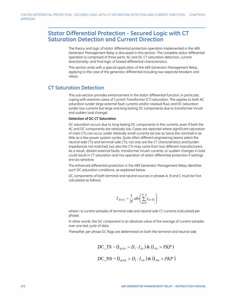
272 489 GENERATOR MANAGEMENT RELAY – INSTRUCTION MANUAL
STATOR DIFFERENTIAL PROTECTION - SECURED LOGIC WITH CT SATURATION DETECTION AND CURRENT DIRECTION CHAPTER 9: APPENDIX
Stator Differential Protection - Secured Logic with CT Saturation Detection and Current Direction
The theory and logic of stator differential protection operation implemented in the 489 Generator Management Relay is discussed in this section. The complete stator differential operation is comprised of three parts: AC and DC CT saturation detection, current directionality, and final logic of biased differential characteristics.
This section ends with a special application of the 489 Generator Management Relay, applying to the case of the generator differential including two separate breakers and relays.
CT Saturation DetectionThis sub-section provides enhancement in the stator differential function, in particular, coping with extreme cases of Current Transformer (CT) saturation. This applies to both AC saturation (under large external fault currents and/or residual flux), and DC saturation (under low currents but large and long lasting DC components due to transformer inrush and sudden load change).
Detection of DC CT Saturation
DC saturation occurs due to long-lasting DC components in the currents, even if both the AC and DC components are relatively low. Cases are reported where significant saturation of main CTs can occur under relatively small currents (as low as twice the nominal) in as little as a few power system cycles. Quite often different engineering teams select the neutral-side CTs and terminal-side CTs; not only are the CT characteristics and burden impedances not matched, but also the CTs may come from two different manufacturers. As a result, distant external faults, transformer inrush currents, or sudden changes in load could result in CT saturation and mis-operation of stator differential protection if settings are too sensitive.
The enhanced differential protection in the 489 Generator Management Relay identifies such DC saturation conditions, as explained below.
DC components of both terminal and neutral sources in phases A, B and C must be first calculated as follows:
where i is current samples of terminal side and neutral side CT currents (calculated per phase).
In other words, the DC component is an absolute value of the average of current samples over one last cycle of data.
Thereafter, per phase DC flags are determined on both the terminal and neutral side.
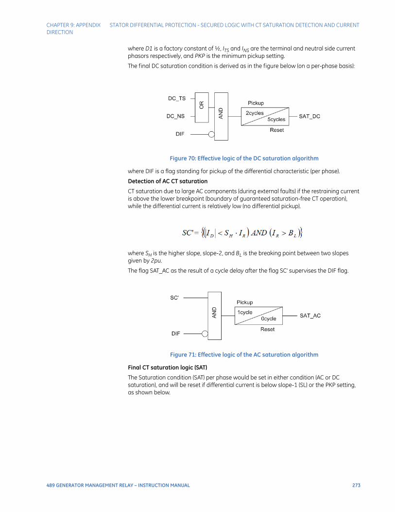
CHAPTER 9: APPENDIX STATOR DIFFERENTIAL PROTECTION - SECURED LOGIC WITH CT SATURATION DETECTION AND CURRENT DIRECTION
489 GENERATOR MANAGEMENT RELAY – INSTRUCTION MANUAL 273
where D1 is a factory constant of ½, ITS and INS are the terminal and neutral side current phasors respectively, and PKP is the minimum pickup setting.
The final DC saturation condition is derived as in the figure below (on a per-phase basis):
Figure 70: Effective logic of the DC saturation algorithm
where DIF is a flag standing for pickup of the differential characteristic (per phase).
Detection of AC CT saturation
CT saturation due to large AC components (during external faults) if the restraining current is above the lower breakpoint (boundary of guaranteed saturation-free CT operation), while the differential current is relatively low (no differential pickup).
where SH is the higher slope, slope-2, and BL is the breaking point between two slopes given by 2pu.
The flag SAT_AC as the result of a cycle delay after the flag SC' supervises the DIF flag.
Figure 71: Effective logic of the AC saturation algorithm
Final CT saturation logic (SAT)
The Saturation condition (SAT) per phase would be set in either condition (AC or DC saturation), and will be reset if differential current is below slope-1 (SL) or the PKP setting, as shown below.
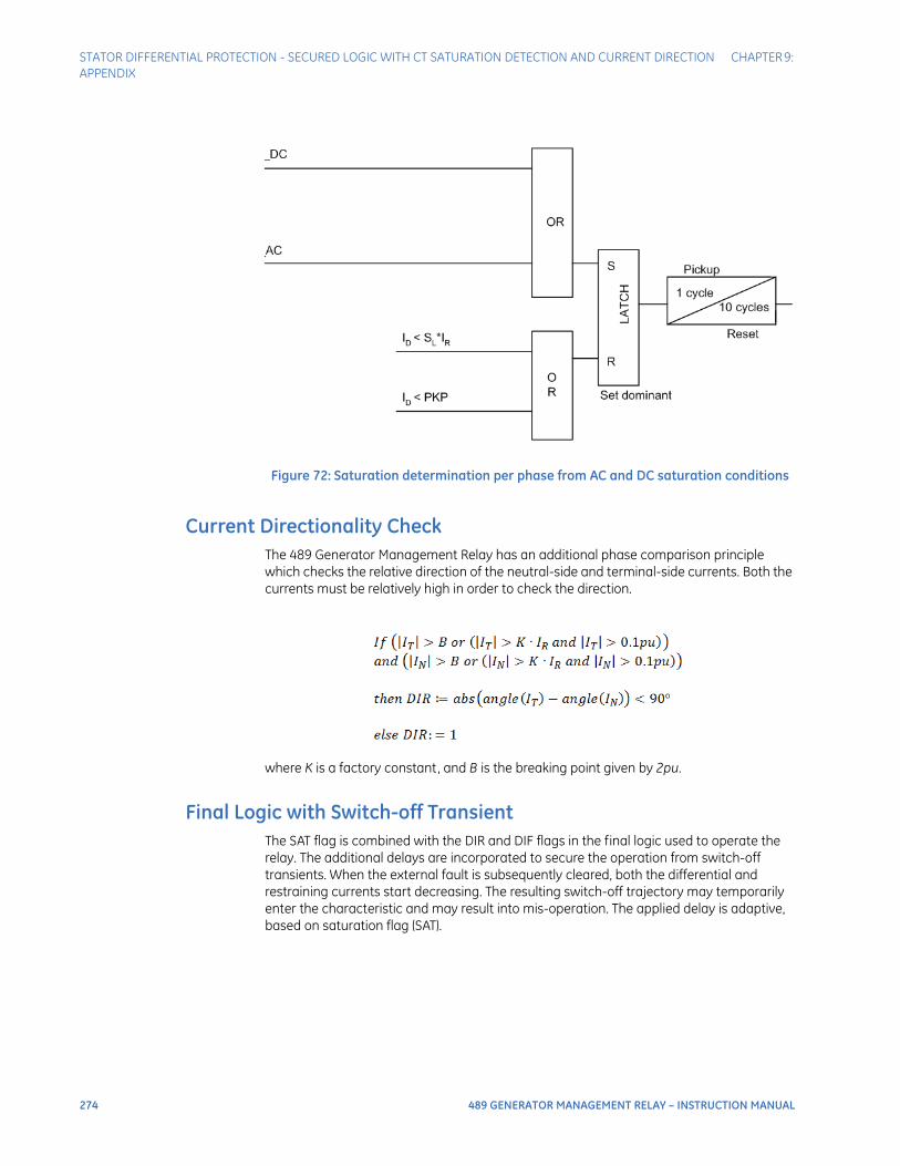
274 489 GENERATOR MANAGEMENT RELAY – INSTRUCTION MANUAL
STATOR DIFFERENTIAL PROTECTION - SECURED LOGIC WITH CT SATURATION DETECTION AND CURRENT DIRECTION CHAPTER 9: APPENDIX
Figure 72: Saturation determination per phase from AC and DC saturation conditions
Current Directionality CheckThe 489 Generator Management Relay has an additional phase comparison principle which checks the relative direction of the neutral-side and terminal-side currents. Both the currents must be relatively high in order to check the direction.
where K is a factory constant, and B is the breaking point given by 2pu.
Final Logic with Switch-off TransientThe SAT flag is combined with the DIR and DIF flags in the final logic used to operate the relay. The additional delays are incorporated to secure the operation from switch-off transients. When the external fault is subsequently cleared, both the differential and restraining currents start decreasing. The resulting switch-off trajectory may temporarily enter the characteristic and may result into mis-operation. The applied delay is adaptive, based on saturation flag (SAT).
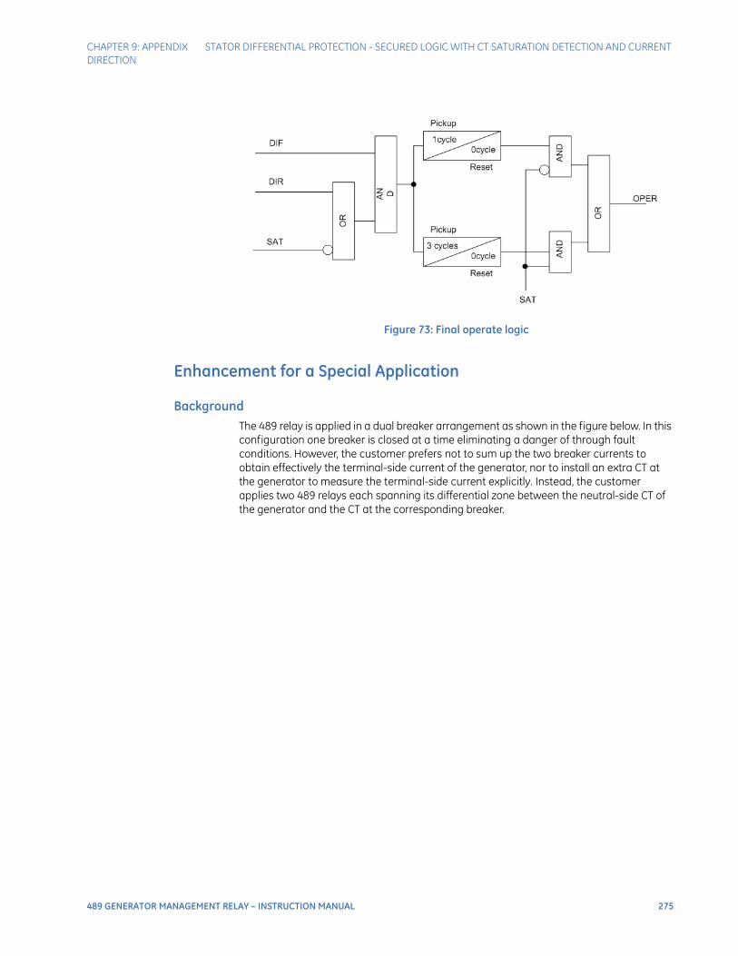
CHAPTER 9: APPENDIX STATOR DIFFERENTIAL PROTECTION - SECURED LOGIC WITH CT SATURATION DETECTION AND CURRENT DIRECTION
489 GENERATOR MANAGEMENT RELAY – INSTRUCTION MANUAL 275
Figure 73: Final operate logic
Enhancement for a Special Application
BackgroundThe 489 relay is applied in a dual breaker arrangement as shown in the figure below. In this configuration one breaker is closed at a time eliminating a danger of through fault conditions. However, the customer prefers not to sum up the two breaker currents to obtain effectively the terminal-side current of the generator, nor to install an extra CT at the generator to measure the terminal-side current explicitly. Instead, the customer applies two 489 relays each spanning its differential zone between the neutral-side CT of the generator and the CT at the corresponding breaker.
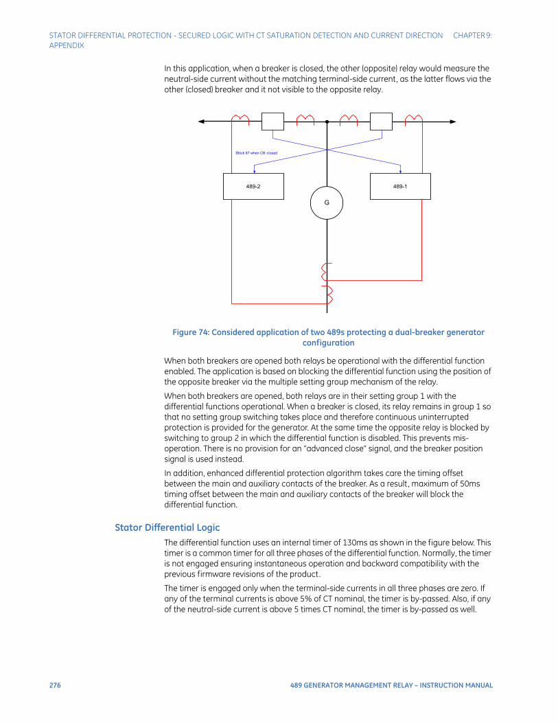
276 489 GENERATOR MANAGEMENT RELAY – INSTRUCTION MANUAL
STATOR DIFFERENTIAL PROTECTION - SECURED LOGIC WITH CT SATURATION DETECTION AND CURRENT DIRECTION CHAPTER 9: APPENDIX
In this application, when a breaker is closed, the other (opposite) relay would measure the neutral-side current without the matching terminal-side current, as the latter flows via the other (closed) breaker and it not visible to the opposite relay.
Figure 74: Considered application of two 489s protecting a dual-breaker generator configuration
When both breakers are opened both relays be operational with the differential function enabled. The application is based on blocking the differential function using the position of the opposite breaker via the multiple setting group mechanism of the relay.
When both breakers are opened, both relays are in their setting group 1 with the differential functions operational. When a breaker is closed, its relay remains in group 1 so that no setting group switching takes place and therefore continuous uninterrupted protection is provided for the generator. At the same time the opposite relay is blocked by switching to group 2 in which the differential function is disabled. This prevents mis-operation. There is no provision for an “advanced close” signal, and the breaker position signal is used instead.
In addition, enhanced differential protection algorithm takes care the timing offset between the main and auxiliary contacts of the breaker. As a result, maximum of 50ms timing offset between the main and auxiliary contacts of the breaker will block the differential function.
Stator Differential LogicThe differential function uses an internal timer of 130ms as shown in the figure below. This timer is a common timer for all three phases of the differential function. Normally, the timer is not engaged ensuring instantaneous operation and backward compatibility with the previous firmware revisions of the product.
The timer is engaged only when the terminal-side currents in all three phases are zero. If any of the terminal currents is above 5% of CT nominal, the timer is by-passed. Also, if any of the neutral-side current is above 5 times CT nominal, the timer is by-passed as well.
Block 87 when CB closed
489-1489-2
G

CHAPTER 9: APPENDIX STATOR DIFFERENTIAL PROTECTION - SECURED LOGIC WITH CT SATURATION DETECTION AND CURRENT DIRECTION
489 GENERATOR MANAGEMENT RELAY – INSTRUCTION MANUAL 277
In this logic the current magnitudes are filtered fundamental frequency components (T stands for terminal-side currents, and N stands for neutral-side currents); PKP denotes the pickup state of the element prior to any user set delay that may or may not be used in a particular application; A, B and C designate phases.
The differential element works as follows:
With the machine under load, the terminal currents are above 5% of CT nominal and no delay is applied to the differential function.
With the machine on-line but with no load (below 5%) the delay is applied. However, should a fault occur at that time, at least one of the terminal current would get elevated cancelling the delay and resulting in an instantaneous trip.
With the opposite breaker being closed as in the considered dual-breaker application, a current is drawn (either transformer inrush or load or both). This will activate the differential characteristic. However, the timer remains engaged because all the terminal currents (ABC) are zero, and all the neutral-side currents (ABC) are below 5 times CT nominal. The timer keeps timing out. However, before it expires the relay switches to group 2 and blocks the differential function. This prevents misoperation.
Figure 75: Enhancements to the stator differential logic
Should a fault occur during the first 50-60ms after closing the breaker, the corresponding relay would trip instantly. Before closing the breaker the corresponding relay too applies a delay. However, once the load/inrush current exceeds 5% of CT nominal, its timer is by-passed and instantaneous protection is provided.
Should a fault occur during generator start-up with both breakers opened, both relays would operate after the extra time delay of 130ms. This delay is acceptable under such conditions. Even this delay will be eliminated if the fault is heavy enough to draw more than 5 times CT nominal from the neutral-side of the generator.
For proper implementation, the internal timer is cleared each time the 87 function becomes enabled (so that a partial time out from the previous “enabled” period does not affect the intended operation).
87 PKP C
87 PKP A
87 PKP B
OR
OR
OR
OR
AN
D
OR
0ms
100ms
130ms
0ms
87 PKP
IT mag A > 0.05pu
IT mag B > 0.05pu
IT mag C > 0.05pu
IN mag A > 5pu
IN mag B > 5pu
IN mag C > 5pu
Normally, no extradelay is applied
With no terminal side currents, adelay of an extra 130ms is appliedto the differential function.
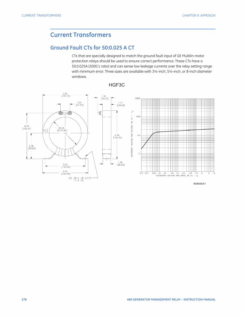
278 489 GENERATOR MANAGEMENT RELAY – INSTRUCTION MANUAL
CURRENT TRANSFORMERS CHAPTER 9: APPENDIX
Current Transformers
Ground Fault CTs for 50:0.025 A CTCTs that are specially designed to match the ground fault input of GE Multilin motor protection relays should be used to ensure correct performance. These CTs have a 50:0.025A (2000:1 ratio) and can sense low leakage currents over the relay setting range with minimum error. Three sizes are available with 3½-inch, 5½-inch, or 8-inch diameter windows.
HGF3C
808840A1
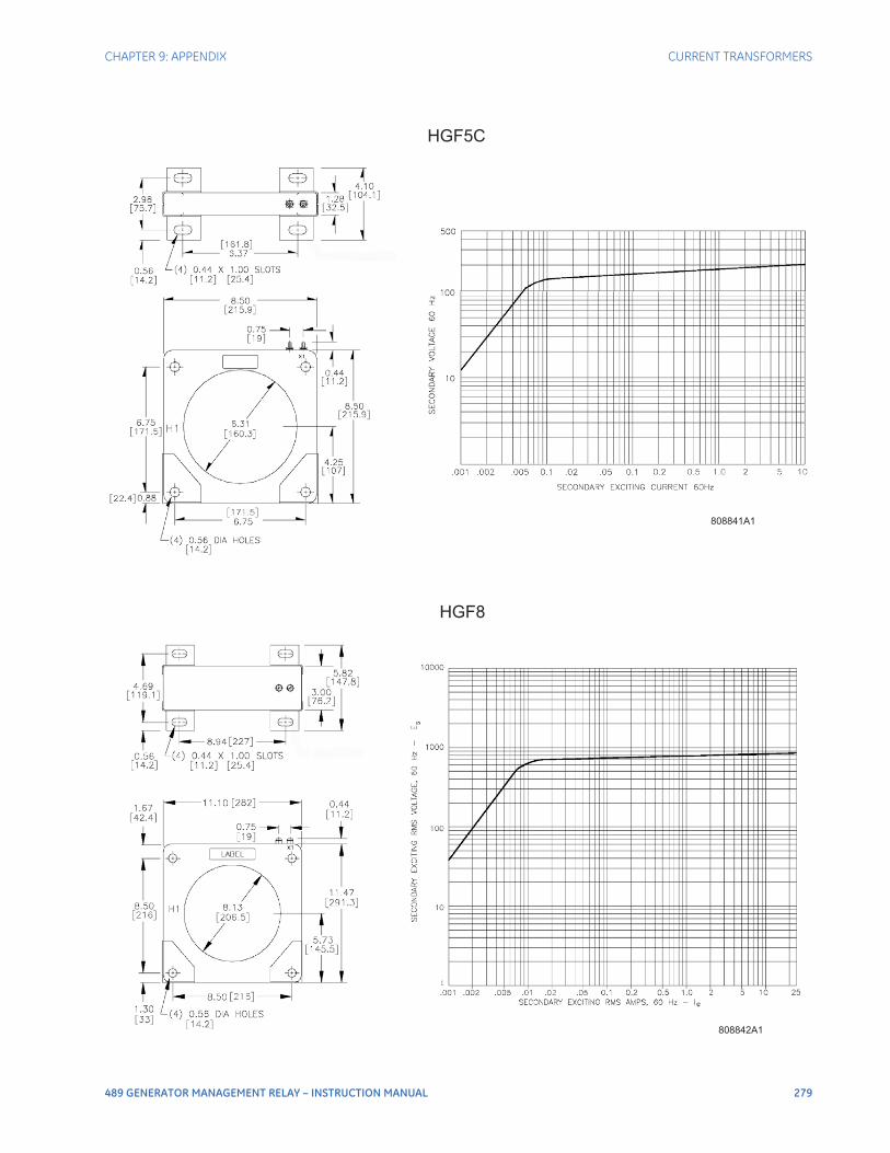
CHAPTER 9: APPENDIX CURRENT TRANSFORMERS
489 GENERATOR MANAGEMENT RELAY – INSTRUCTION MANUAL 279
HGF5C
808841A1
HGF8
808842A1
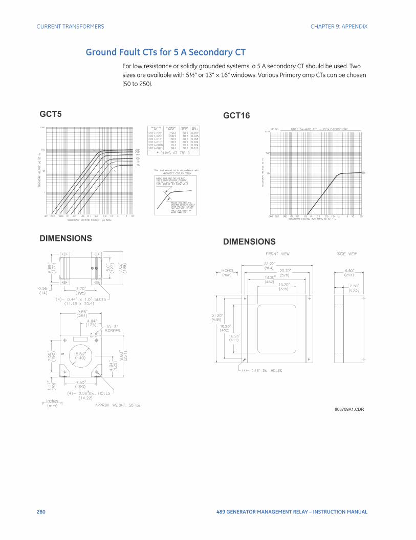
280 489 GENERATOR MANAGEMENT RELAY – INSTRUCTION MANUAL
CURRENT TRANSFORMERS CHAPTER 9: APPENDIX
Ground Fault CTs for 5 A Secondary CTFor low resistance or solidly grounded systems, a 5 A secondary CT should be used. Two sizes are available with 5½” or 13” × 16” windows. Various Primary amp CTs can be chosen (50 to 250).
808709A1.CDR
GCT5 GCT16
DIMENSIONSDIMENSIONS

CHAPTER 9: APPENDIX CURRENT TRANSFORMERS
489 GENERATOR MANAGEMENT RELAY – INSTRUCTION MANUAL 281
Phase CTsCurrent transformers in most common ratios from 50:5 to 1000:5 are available for use as phase current inputs with motor protection relays. These come with mounting hardware and are also available with 1 A secondaries. Voltage class: 600 V BIL, 10 KV.
808712A1.CDR
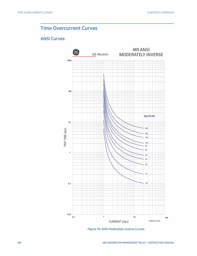
282 489 GENERATOR MANAGEMENT RELAY – INSTRUCTION MANUAL
TIME OVERCURRENT CURVES CHAPTER 9: APPENDIX
Time Overcurrent Curves
ANSI Curves
Figure 76: ANSI Moderately Inverse Curves
0.01
0.1
1
10
100
1000
0.1 1 10 100
808802A4.CDRCURRENT (I/Ipu)
TR
IPT
IME
(sec)
489 ANSIMODERATELY INVERSE
0.5
1.0
2.0
3.0
4.0
6.0
8.0
10.0
15.0
20.0
30.0
MULTIPLIER
GE Multilin
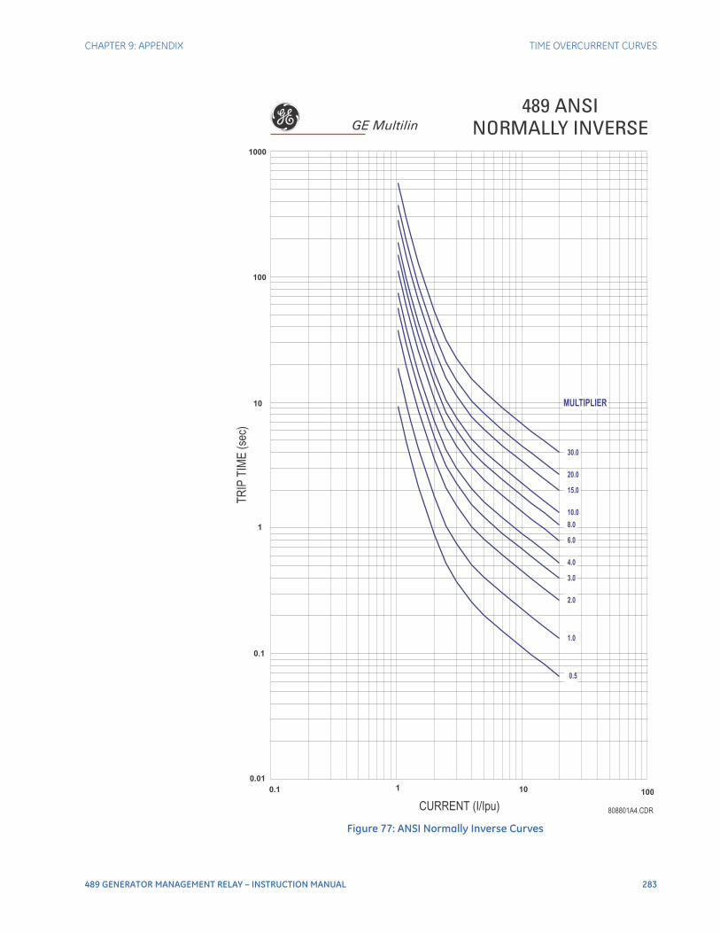
CHAPTER 9: APPENDIX TIME OVERCURRENT CURVES
489 GENERATOR MANAGEMENT RELAY – INSTRUCTION MANUAL 283
Figure 77: ANSI Normally Inverse Curves
0.01
0.1
1
10
100
1000
0.1 1 10 100
CURRENT (I/Ipu)
TR
IPT
IME
(sec)
808801A4.CDR
489 ANSINORMALLY INVERSE
0.5
1.0
2.0
3.0
4.0
6.0
8.0
10.0
15.0
20.0
30.0
MULTIPLIER
GE Multilin

284 489 GENERATOR MANAGEMENT RELAY – INSTRUCTION MANUAL
TIME OVERCURRENT CURVES CHAPTER 9: APPENDIX
Figure 78: ANSI Very Inverse Curves
0.01
808800A4.DWG
0.1
1
10
100
1000
0.1 1 10 100
CURRENT (I/Ipu)
TR
IPT
IME
(sec)
489 ANSIVERY INVERSE
0.5
1.0
2.0
3.0
4.0
6.0
8.0
10.0
15.0
20.0
30.0
MULTIPLIER
GE Multilin
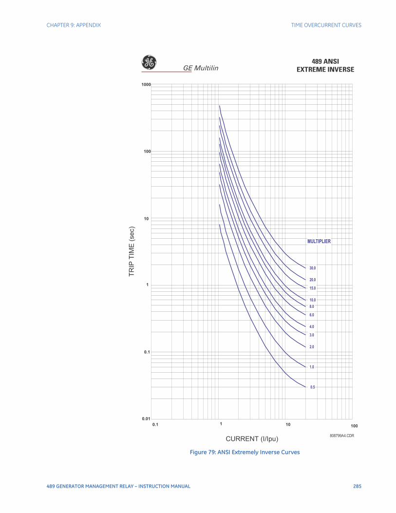
CHAPTER 9: APPENDIX TIME OVERCURRENT CURVES
489 GENERATOR MANAGEMENT RELAY – INSTRUCTION MANUAL 285
Figure 79: ANSI Extremely Inverse Curves
0.01
808799A4.CDR
0.1
1
10
100
1000
0.1 1 10 100
CURRENT (I/Ipu)
TR
IPT
IME
(sec)
489 ANSIEXTREME INVERSE
0.5
1.0
2.0
3.0
4.0
6.0
8.0
10.0
15.0
20.0
30.0
MULTIPLIER
GE Multilin
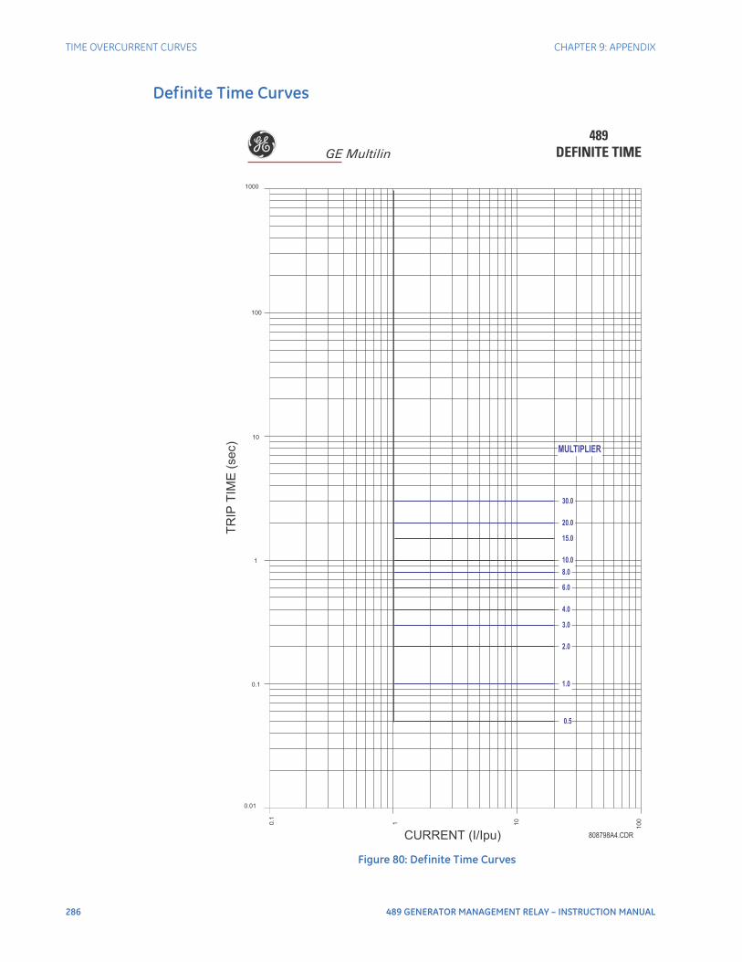
286 489 GENERATOR MANAGEMENT RELAY – INSTRUCTION MANUAL
TIME OVERCURRENT CURVES CHAPTER 9: APPENDIX
Definite Time Curves
Figure 80: Definite Time Curves
489DEFINITE TIME
0.5
1.0
2.0
3.0
4.0
6.0
8.0
10.0
15.0
20.0
30.0
0.01
0.1
1
10
100
1000
0.1
1 10
10
0
CURRENT (I/Ipu)
TR
IPT
IME
(se
c)
MULTIPLIER
808798A4.CDR
GE Multilin
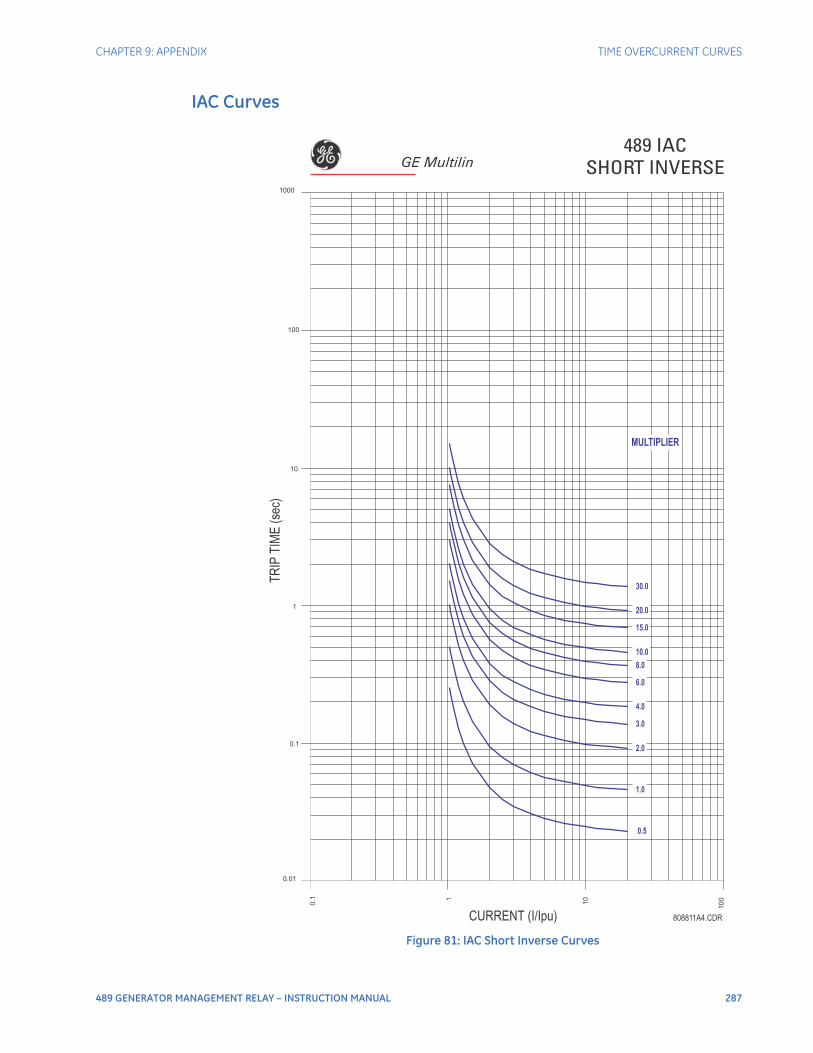
CHAPTER 9: APPENDIX TIME OVERCURRENT CURVES
489 GENERATOR MANAGEMENT RELAY – INSTRUCTION MANUAL 287
IAC Curves
Figure 81: IAC Short Inverse Curves
0.5
1.0
2.0
3.0
4.0
6.0
8.0
10.0
15.0
20.0
30.0
0.01
0.1
1
10
100
1000
0.1 1
10
100
CURRENT (I/Ipu)
TR
IPT
IME
(sec)
MULTIPLIER
808811A4.CDR
489 IACSHORT INVERSEGE Multilin
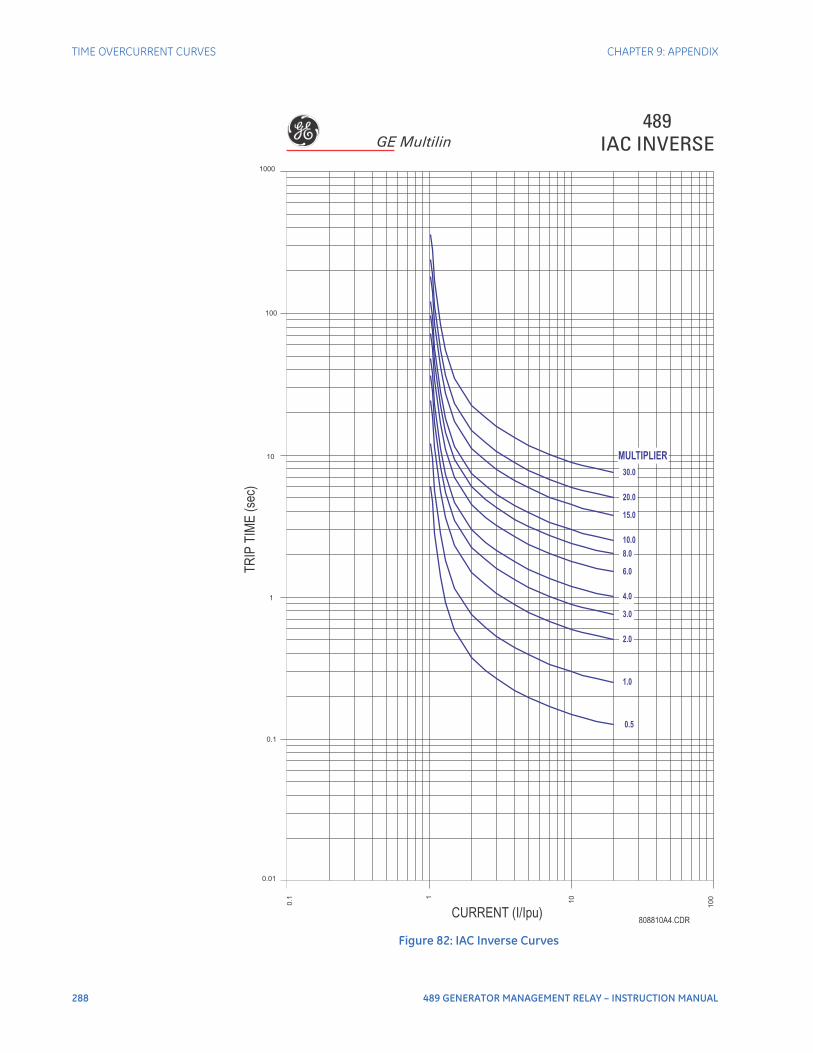
288 489 GENERATOR MANAGEMENT RELAY – INSTRUCTION MANUAL
TIME OVERCURRENT CURVES CHAPTER 9: APPENDIX
Figure 82: IAC Inverse Curves
0.5
1.0
2.0
3.0
4.0
6.0
8.0
10.0
15.0
20.0
30.0
0.01
0.1
1
10
100
1000
0.1 1
10
100
CURRENT (I/Ipu)
TR
IPT
IME
(sec)
MULTIPLIER
489IAC INVERSE
808810A4.CDR
GE Multilin
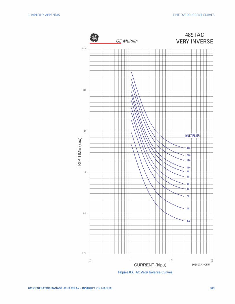
CHAPTER 9: APPENDIX TIME OVERCURRENT CURVES
489 GENERATOR MANAGEMENT RELAY – INSTRUCTION MANUAL 289
Figure 83: IAC Very Inverse Curves
0.5
1.0
2.0
3.0
4.0
6.0
8.0
10.0
15.0
20.0
30.0
0.01
0.1
1
10
100
1000
0.1 1
10
100
CURRENT (I/Ipu)
TR
IPT
IME
(sec)
MULTIPLIER
489 IACVERY INVERSE
808807A3.CDR
GE Multilin
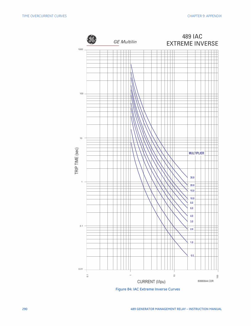
290 489 GENERATOR MANAGEMENT RELAY – INSTRUCTION MANUAL
TIME OVERCURRENT CURVES CHAPTER 9: APPENDIX
Figure 84: IAC Extreme Inverse Curves
0.5
1.0
2.0
3.0
4.0
6.0
8.0
10.0
15.0
20.0
30.0
0.01
0.1
1
10
100
1000
0.1 1
10
10
0
808806A4.CDRCURRENT (I/Ipu)
TR
IPT
IME
(sec)
MULTIPLIER
489 IACEXTREME INVERSEGE Multilin
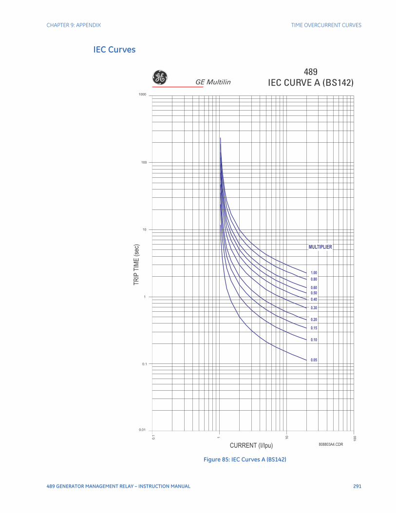
CHAPTER 9: APPENDIX TIME OVERCURRENT CURVES
489 GENERATOR MANAGEMENT RELAY – INSTRUCTION MANUAL 291
IEC Curves
Figure 85: IEC Curves A (BS142)
0.05
0.10
0.15
0.20
0.30
0.40
0.50
0.60
0.80
1.00
0.01
0.1
1
10
100
1000
0.1 1 10
100
CURRENT (I/Ipu)
TR
IPT
IME
(sec)
MULTIPLIER
489IEC CURVE A (BS142)
808803A4.CDR
GE Multilin
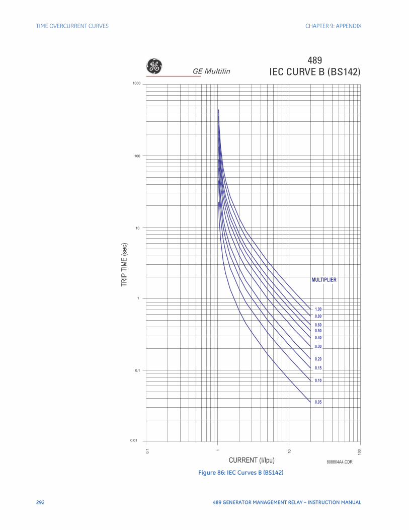
292 489 GENERATOR MANAGEMENT RELAY – INSTRUCTION MANUAL
TIME OVERCURRENT CURVES CHAPTER 9: APPENDIX
Figure 86: IEC Curves B (BS142)
0.05
0.10
0.15
0.20
0.30
0.40
0.50
0.60
0.80
1.00
0.01
0.1
1
10
100
1000
0.1 1
10
100
CURRENT (I/Ipu)
TR
IPT
IME
(sec)
MULTIPLIER
489IEC CURVE B (BS142)
808804A4.CDR
GE Multilin
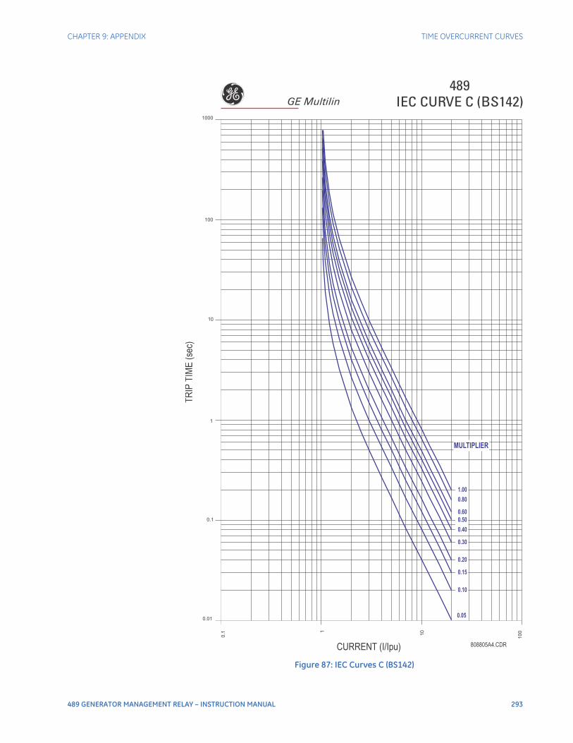
CHAPTER 9: APPENDIX TIME OVERCURRENT CURVES
489 GENERATOR MANAGEMENT RELAY – INSTRUCTION MANUAL 293
Figure 87: IEC Curves C (BS142)
0.05
0.10
0.15
0.20
0.30
0.40
0.50
0.60
0.80
1.00
0.01
0.1
1
10
100
1000
0.1
1
10
100
CURRENT (I/Ipu)
TR
IPT
IME
(sec)
MULTIPLIER
489IEC CURVE C (BS142)
808805A4.CDR
GE Multilin
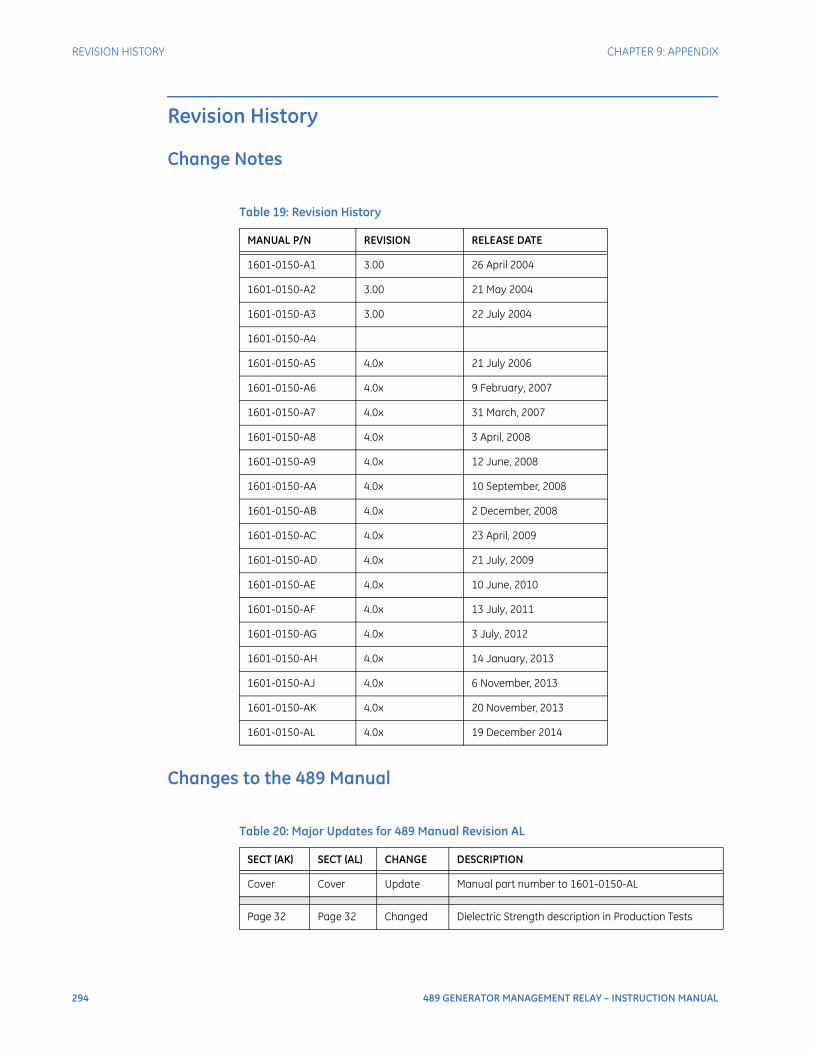
294 489 GENERATOR MANAGEMENT RELAY – INSTRUCTION MANUAL
REVISION HISTORY CHAPTER 9: APPENDIX
Revision History
Change Notes
Changes to the 489 Manual
Table 19: Revision History
MANUAL P/N REVISION RELEASE DATE
1601-0150-A1 3.00 26 April 2004
1601-0150-A2 3.00 21 May 2004
1601-0150-A3 3.00 22 July 2004
1601-0150-A4
1601-0150-A5 4.0x 21 July 2006
1601-0150-A6 4.0x 9 February, 2007
1601-0150-A7 4.0x 31 March, 2007
1601-0150-A8 4.0x 3 April, 2008
1601-0150-A9 4.0x 12 June, 2008
1601-0150-AA 4.0x 10 September, 2008
1601-0150-AB 4.0x 2 December, 2008
1601-0150-AC 4.0x 23 April, 2009
1601-0150-AD 4.0x 21 July, 2009
1601-0150-AE 4.0x 10 June, 2010
1601-0150-AF 4.0x 13 July, 2011
1601-0150-AG 4.0x 3 July, 2012
1601-0150-AH 4.0x 14 January, 2013
1601-0150-AJ 4.0x 6 November, 2013
1601-0150-AK 4.0x 20 November, 2013
1601-0150-AL 4.0x 19 December 2014
Table 20: Major Updates for 489 Manual Revision AL
SECT (AK) SECT (AL) CHANGE DESCRIPTION
Cover Cover Update Manual part number to 1601-0150-AL
Page 32 Page 32 Changed Dielectric Strength description in Production Tests
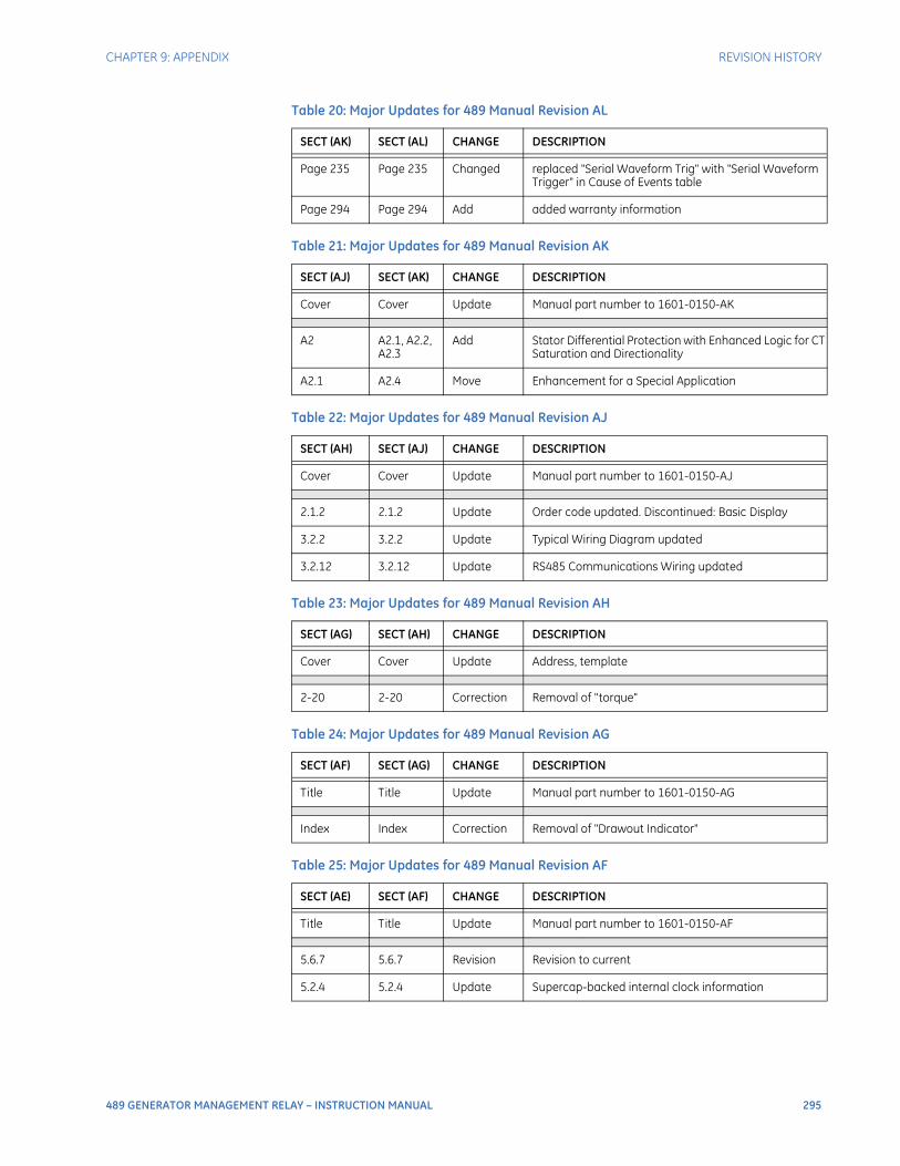
CHAPTER 9: APPENDIX REVISION HISTORY
489 GENERATOR MANAGEMENT RELAY – INSTRUCTION MANUAL 295
Page 235 Page 235 Changed replaced "Serial Waveform Trig" with "Serial Waveform Trigger" in Cause of Events table
Page 294 Page 294 Add added warranty information
Table 21: Major Updates for 489 Manual Revision AK
SECT (AJ) SECT (AK) CHANGE DESCRIPTION
Cover Cover Update Manual part number to 1601-0150-AK
A2 A2.1, A2.2, A2.3
Add Stator Differential Protection with Enhanced Logic for CT Saturation and Directionality
A2.1 A2.4 Move Enhancement for a Special Application
Table 22: Major Updates for 489 Manual Revision AJ
SECT (AH) SECT (AJ) CHANGE DESCRIPTION
Cover Cover Update Manual part number to 1601-0150-AJ
2.1.2 2.1.2 Update Order code updated. Discontinued: Basic Display
3.2.2 3.2.2 Update Typical Wiring Diagram updated
3.2.12 3.2.12 Update RS485 Communications Wiring updated
Table 23: Major Updates for 489 Manual Revision AH
SECT (AG) SECT (AH) CHANGE DESCRIPTION
Cover Cover Update Address, template
2-20 2-20 Correction Removal of "torque"
Table 24: Major Updates for 489 Manual Revision AG
SECT (AF) SECT (AG) CHANGE DESCRIPTION
Title Title Update Manual part number to 1601-0150-AG
Index Index Correction Removal of "Drawout Indicator"
Table 25: Major Updates for 489 Manual Revision AF
SECT (AE) SECT (AF) CHANGE DESCRIPTION
Title Title Update Manual part number to 1601-0150-AF
5.6.7 5.6.7 Revision Revision to current
5.2.4 5.2.4 Update Supercap-backed internal clock information
Table 20: Major Updates for 489 Manual Revision AL
SECT (AK) SECT (AL) CHANGE DESCRIPTION
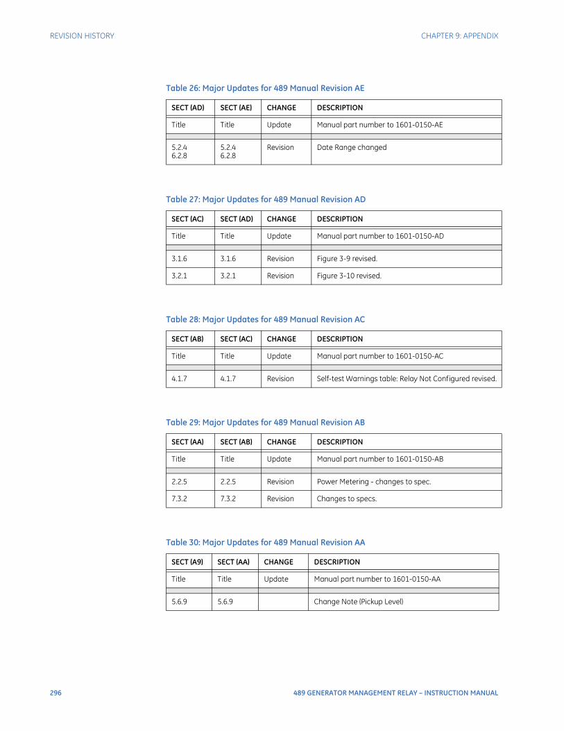
296 489 GENERATOR MANAGEMENT RELAY – INSTRUCTION MANUAL
REVISION HISTORY CHAPTER 9: APPENDIX
Table 26: Major Updates for 489 Manual Revision AE
SECT (AD) SECT (AE) CHANGE DESCRIPTION
Title Title Update Manual part number to 1601-0150-AE
5.2.46.2.8
5.2.46.2.8
Revision Date Range changed
Table 27: Major Updates for 489 Manual Revision AD
SECT (AC) SECT (AD) CHANGE DESCRIPTION
Title Title Update Manual part number to 1601-0150-AD
3.1.6 3.1.6 Revision Figure 3-9 revised.
3.2.1 3.2.1 Revision Figure 3-10 revised.
Table 28: Major Updates for 489 Manual Revision AC
SECT (AB) SECT (AC) CHANGE DESCRIPTION
Title Title Update Manual part number to 1601-0150-AC
4.1.7 4.1.7 Revision Self-test Warnings table: Relay Not Configured revised.
Table 29: Major Updates for 489 Manual Revision AB
SECT (AA) SECT (AB) CHANGE DESCRIPTION
Title Title Update Manual part number to 1601-0150-AB
2.2.5 2.2.5 Revision Power Metering - changes to spec.
7.3.2 7.3.2 Revision Changes to specs.
Table 30: Major Updates for 489 Manual Revision AA
SECT (A9) SECT (AA) CHANGE DESCRIPTION
Title Title Update Manual part number to 1601-0150-AA
5.6.9 5.6.9 Change Note (Pickup Level)
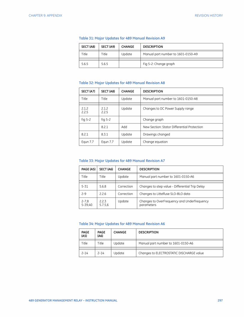
CHAPTER 9: APPENDIX REVISION HISTORY
489 GENERATOR MANAGEMENT RELAY – INSTRUCTION MANUAL 297
Table 31: Major Updates for 489 Manual Revision A9
SECT (A8) SECT (A9) CHANGE DESCRIPTION
Title Title Update Manual part number to 1601-0150-A9
5.6.5 5.6.5 Fig 5-2: Change graph
Table 32: Major Updates for 489 Manual Revision A8
SECT (A7) SECT (A8) CHANGE DESCRIPTION
Title Title Update Manual part number to 1601-0150-A8
2.1.22.2.5
2.1.22.2.5
Update Changes to DC Power Supply range
fig 5-2 fig 5-2 Change graph
8.2.1 Add New Section: Stator Differential Protection
8.2.1 8.3.1 Update Drawings changed
Equn 7.7 Equn 7.7 Update Change equation
Table 33: Major Updates for 489 Manual Revision A7
PAGE (A5) SECT (A6) CHANGE DESCRIPTION
Title Title Update Manual part number to 1601-0150-A6
5-31 5.6.8 Correction Changes to step value - Differential Trip Delay
2-9 2.2.6 Correction Changes to Littelfuse SLO-BLO data
2-7,85-39,40
2.2.35.7.5,6
Update Changes to OverFrequency and Underfrequency parameters
Table 34: Major Updates for 489 Manual Revision A6
PAGE (A5)
PAGE (A6)
CHANGE DESCRIPTION
Title Title Update Manual part number to 1601-0150-A6
2-14 2-14 Update Changes to ELECTROSTATIC DISCHARGE value
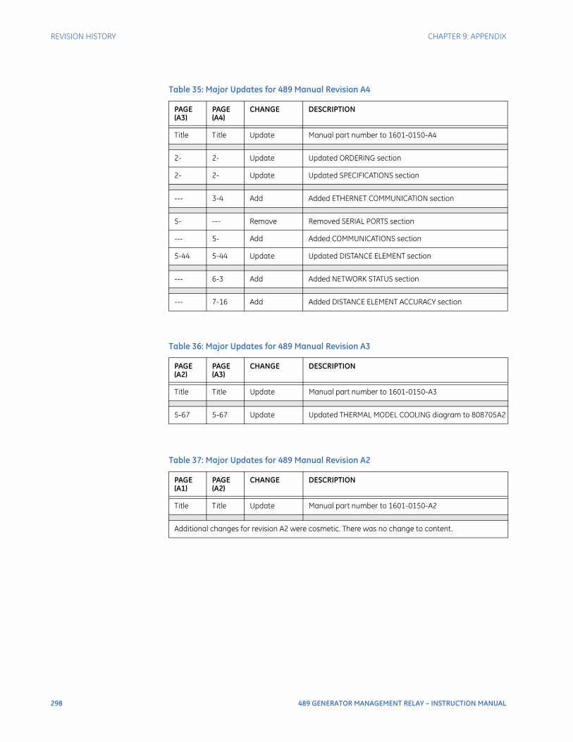
298 489 GENERATOR MANAGEMENT RELAY – INSTRUCTION MANUAL
REVISION HISTORY CHAPTER 9: APPENDIX
Table 35: Major Updates for 489 Manual Revision A4
PAGE (A3)
PAGE (A4)
CHANGE DESCRIPTION
Title Title Update Manual part number to 1601-0150-A4
2- 2- Update Updated ORDERING section
2- 2- Update Updated SPECIFICATIONS section
--- 3-4 Add Added ETHERNET COMMUNICATION section
5- --- Remove Removed SERIAL PORTS section
--- 5- Add Added COMMUNICATIONS section
5-44 5-44 Update Updated DISTANCE ELEMENT section
--- 6-3 Add Added NETWORK STATUS section
--- 7-16 Add Added DISTANCE ELEMENT ACCURACY section
Table 36: Major Updates for 489 Manual Revision A3
PAGE (A2)
PAGE (A3)
CHANGE DESCRIPTION
Title Title Update Manual part number to 1601-0150-A3
5-67 5-67 Update Updated THERMAL MODEL COOLING diagram to 808705A2
Table 37: Major Updates for 489 Manual Revision A2
PAGE (A1)
PAGE (A2)
CHANGE DESCRIPTION
Title Title Update Manual part number to 1601-0150-A2
Additional changes for revision A2 were cosmetic. There was no change to content.

CHAPTER 9: APPENDIX EU DECLARATION OF CONFORMITY
489 GENERATOR MANAGEMENT RELAY – INSTRUCTION MANUAL 299
EU Declaration of Conformity
EU Declaration of Conformity

300 489 GENERATOR MANAGEMENT RELAY – INSTRUCTION MANUAL
WARRANTY CHAPTER 9: APPENDIX
WarrantyFor products shipped as of 1 October 2013, GE Digital Energy warrants most of its GE manufactured products for 10 years. For warranty details including any limitations and disclaimers, see the GE Digital Energy Terms and Conditions at https://www.gedigitalenergy.com/multilin/warranty.htm
For products shipped before 1 October 2013, the standard 24-month warranty applies.
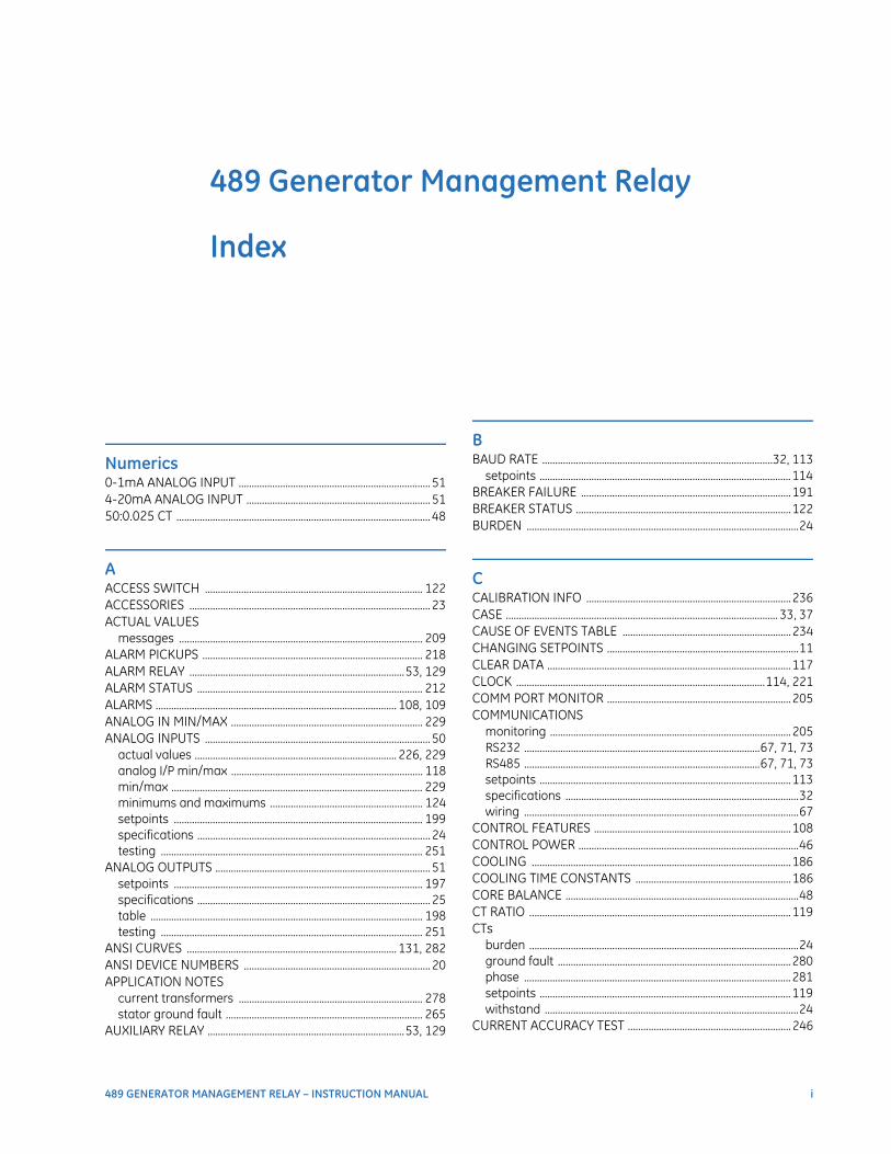
489 GENERATOR MANAGEMENT RELAY – INSTRUCTION MANUAL i
489 Generator Management Relay
Index
Index
Numerics0-1mA ANALOG INPUT .......................................................................... 514-20mA ANALOG INPUT ....................................................................... 5150:0.025 CT .................................................................................................. 48
AACCESS SWITCH .................................................................................... 122ACCESSORIES ............................................................................................. 23ACTUAL VALUES
messages .............................................................................................. 209ALARM PICKUPS ..................................................................................... 218ALARM RELAY ...................................................................................53, 129ALARM STATUS ....................................................................................... 212ALARMS ............................................................................................. 108, 109ANALOG IN MIN/MAX .......................................................................... 229ANALOG INPUTS ....................................................................................... 50
actual values .............................................................................. 226, 229analog I/P min/max .......................................................................... 118min/max ................................................................................................. 229minimums and maximums ........................................................... 124setpoints ................................................................................................ 199specifications .......................................................................................... 24testing ..................................................................................................... 251
ANALOG OUTPUTS ................................................................................... 51setpoints ................................................................................................ 197specifications .......................................................................................... 25table ......................................................................................................... 198testing ..................................................................................................... 251
ANSI CURVES ................................................................................. 131, 282ANSI DEVICE NUMBERS ........................................................................ 20APPLICATION NOTES
current transformers ....................................................................... 278stator ground fault ............................................................................ 265
AUXILIARY RELAY ............................................................................53, 129
BBAUD RATE .........................................................................................32, 113
setpoints .................................................................................................114BREAKER FAILURE .................................................................................191BREAKER STATUS ...................................................................................122BURDEN .........................................................................................................24
CCALIBRATION INFO ...............................................................................236CASE ......................................................................................................... 33, 37CAUSE OF EVENTS TABLE .................................................................234CHANGING SETPOINTS ..........................................................................11CLEAR DATA ..............................................................................................117CLOCK ................................................................................................114, 221COMM PORT MONITOR .......................................................................205COMMUNICATIONS
monitoring .............................................................................................205RS232 ...........................................................................................67, 71, 73RS485 ...........................................................................................67, 71, 73setpoints .................................................................................................113specifications ..........................................................................................32wiring ..........................................................................................................67
CONTROL FEATURES ............................................................................108CONTROL POWER .....................................................................................46COOLING ....................................................................................................186COOLING TIME CONSTANTS ............................................................186CORE BALANCE ..........................................................................................48CT RATIO .....................................................................................................119CTs
burden ........................................................................................................24ground fault ..........................................................................................280phase .......................................................................................................281setpoints .................................................................................................119withstand ..................................................................................................24
CURRENT ACCURACY TEST ...............................................................246
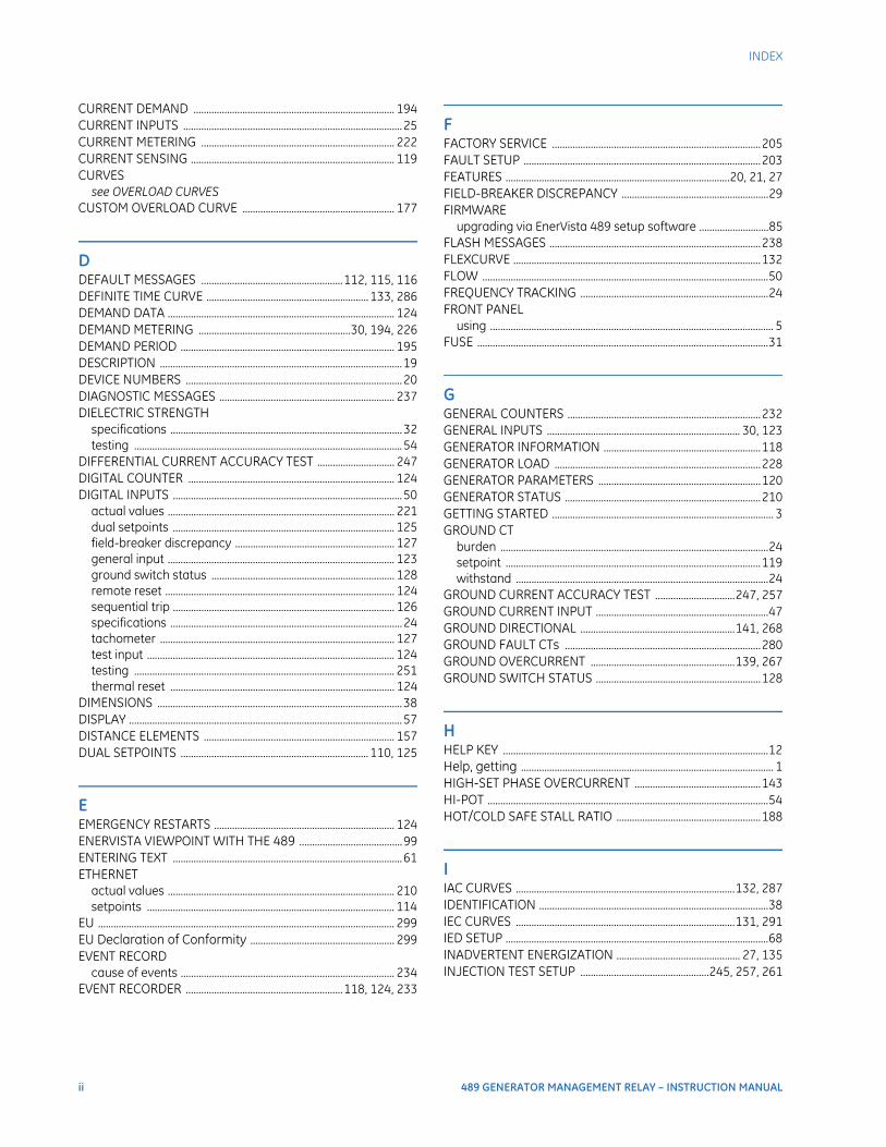
ii 489 GENERATOR MANAGEMENT RELAY – INSTRUCTION MANUAL
INDEX
CURRENT DEMAND .............................................................................. 194CURRENT INPUTS .....................................................................................25CURRENT METERING ........................................................................... 222CURRENT SENSING ............................................................................... 119CURVES
see OVERLOAD CURVESCUSTOM OVERLOAD CURVE ........................................................... 177
DDEFAULT MESSAGES .......................................................112, 115, 116DEFINITE TIME CURVE ............................................................... 133, 286DEMAND DATA ........................................................................................ 124DEMAND METERING ...........................................................30, 194, 226DEMAND PERIOD ................................................................................... 195DESCRIPTION ..............................................................................................19DEVICE NUMBERS ....................................................................................20DIAGNOSTIC MESSAGES .................................................................... 237DIELECTRIC STRENGTH
specifications ..........................................................................................32testing ........................................................................................................54
DIFFERENTIAL CURRENT ACCURACY TEST .............................. 247DIGITAL COUNTER ................................................................................ 124DIGITAL INPUTS .........................................................................................50
actual values ........................................................................................ 221dual setpoints ...................................................................................... 125field-breaker discrepancy .............................................................. 127general input ........................................................................................ 123ground switch status ....................................................................... 128remote reset ......................................................................................... 124sequential trip ...................................................................................... 126specifications ..........................................................................................24tachometer ........................................................................................... 127test input ................................................................................................ 124testing ..................................................................................................... 251thermal reset ....................................................................................... 124
DIMENSIONS ...............................................................................................38DISPLAY ..........................................................................................................57DISTANCE ELEMENTS .......................................................................... 157DUAL SETPOINTS ......................................................................... 110, 125
EEMERGENCY RESTARTS ...................................................................... 124ENERVISTA VIEWPOINT WITH THE 489 ........................................99ENTERING TEXT .........................................................................................61ETHERNET
actual values ........................................................................................ 210setpoints ................................................................................................ 114
EU ................................................................................................................... 299EU Declaration of Conformity ........................................................ 299EVENT RECORD
cause of events ................................................................................... 234EVENT RECORDER .............................................................118, 124, 233
FFACTORY SERVICE .................................................................................205FAULT SETUP ............................................................................................203FEATURES .......................................................................................20, 21, 27FIELD-BREAKER DISCREPANCY .........................................................29FIRMWARE
upgrading via EnerVista 489 setup software ...........................85FLASH MESSAGES ..................................................................................238FLEXCURVE ................................................................................................132FLOW ...............................................................................................................50FREQUENCY TRACKING .........................................................................24FRONT PANEL
using .............................................................................................................. 5FUSE .................................................................................................................31
GGENERAL COUNTERS ...........................................................................232GENERAL INPUTS ........................................................................... 30, 123GENERATOR INFORMATION .............................................................118GENERATOR LOAD ................................................................................228GENERATOR PARAMETERS ...............................................................120GENERATOR STATUS ............................................................................210GETTING STARTED ...................................................................................... 3GROUND CT
burden ........................................................................................................24setpoint ...................................................................................................119withstand ..................................................................................................24
GROUND CURRENT ACCURACY TEST ...............................247, 257GROUND CURRENT INPUT ...................................................................47GROUND DIRECTIONAL ............................................................141, 268GROUND FAULT CTs ............................................................................280GROUND OVERCURRENT ........................................................139, 267GROUND SWITCH STATUS ................................................................128
HHELP KEY .......................................................................................................12Help, getting .................................................................................................. 1HIGH-SET PHASE OVERCURRENT .................................................143HI-POT .............................................................................................................54HOT/COLD SAFE STALL RATIO ........................................................188
IIAC CURVES .....................................................................................132, 287IDENTIFICATION .........................................................................................38IEC CURVES .....................................................................................131, 291IED SETUP ......................................................................................................68INADVERTENT ENERGIZATION ................................................ 27, 135INJECTION TEST SETUP ..................................................245, 257, 261
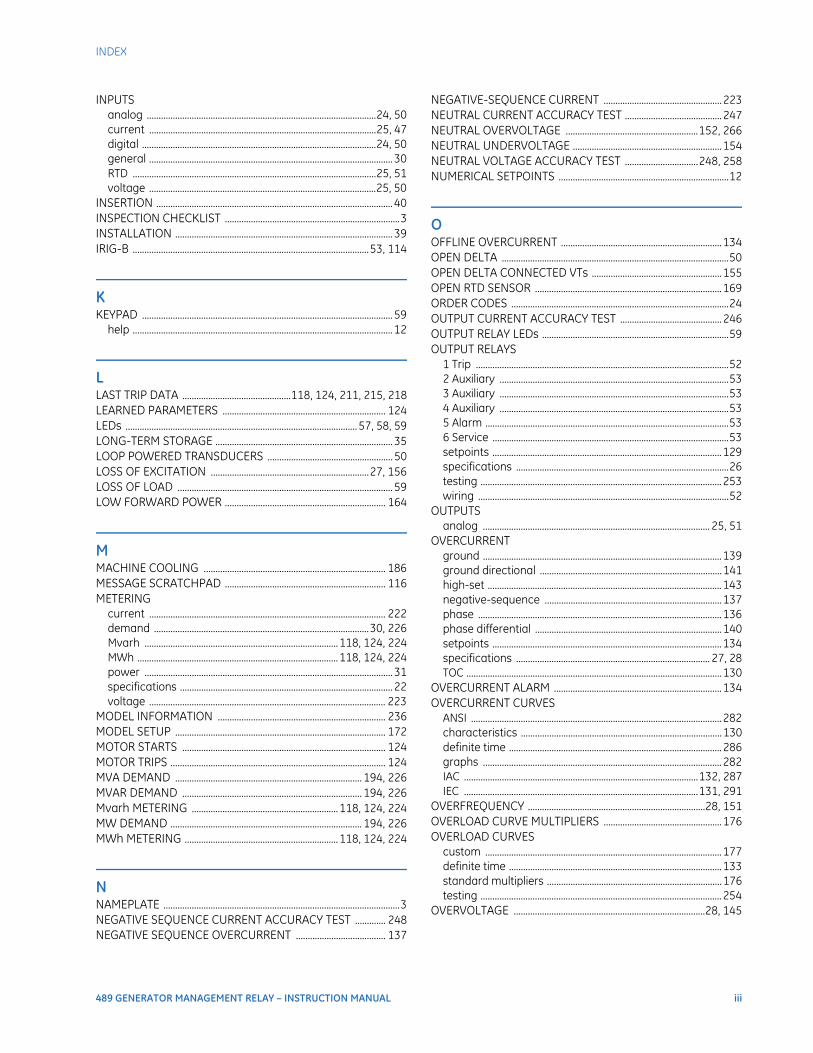
INDEX
489 GENERATOR MANAGEMENT RELAY – INSTRUCTION MANUAL iii
INPUTSanalog .................................................................................................24, 50current ................................................................................................25, 47digital ...................................................................................................24, 50general ....................................................................................................... 30RTD .......................................................................................................25, 51voltage ................................................................................................25, 50
INSERTION .................................................................................................... 40INSPECTION CHECKLIST ..........................................................................3INSTALLATION ............................................................................................ 39IRIG-B ....................................................................................................53, 114
KKEYPAD .......................................................................................................... 59
help .............................................................................................................. 12
LLAST TRIP DATA ..............................................118, 124, 211, 215, 218LEARNED PARAMETERS ..................................................................... 124LEDs ..................................................................................................57, 58, 59LONG-TERM STORAGE ........................................................................... 35LOOP POWERED TRANSDUCERS ..................................................... 50LOSS OF EXCITATION ...................................................................27, 156LOSS OF LOAD ........................................................................................... 59LOW FORWARD POWER .................................................................... 164
MMACHINE COOLING ............................................................................. 186MESSAGE SCRATCHPAD .................................................................... 116METERING
current .................................................................................................... 222demand ...........................................................................................30, 226Mvarh ..................................................................................118, 124, 224MWh .....................................................................................118, 124, 224power ......................................................................................................... 31specifications .......................................................................................... 22voltage .................................................................................................... 223
MODEL INFORMATION ....................................................................... 236MODEL SETUP ......................................................................................... 172MOTOR STARTS ...................................................................................... 124MOTOR TRIPS ........................................................................................... 124MVA DEMAND ............................................................................... 194, 226MVAR DEMAND ............................................................................ 194, 226Mvarh METERING ..............................................................118, 124, 224MW DEMAND ................................................................................. 194, 226MWh METERING .................................................................118, 124, 224
NNAMEPLATE ....................................................................................................3NEGATIVE SEQUENCE CURRENT ACCURACY TEST ............. 248NEGATIVE SEQUENCE OVERCURRENT ...................................... 137
NEGATIVE-SEQUENCE CURRENT ..................................................223NEUTRAL CURRENT ACCURACY TEST .........................................247NEUTRAL OVERVOLTAGE ........................................................152, 266NEUTRAL UNDERVOLTAGE ...............................................................154NEUTRAL VOLTAGE ACCURACY TEST ...............................248, 258NUMERICAL SETPOINTS ........................................................................12
OOFFLINE OVERCURRENT ....................................................................134OPEN DELTA ................................................................................................50OPEN DELTA CONNECTED VTs .......................................................155OPEN RTD SENSOR ...............................................................................169ORDER CODES ............................................................................................24OUTPUT CURRENT ACCURACY TEST ...........................................246OUTPUT RELAY LEDs ...............................................................................59OUTPUT RELAYS
1 Trip ...........................................................................................................522 Auxiliary .................................................................................................533 Auxiliary .................................................................................................534 Auxiliary .................................................................................................535 Alarm .......................................................................................................536 Service ....................................................................................................53setpoints .................................................................................................129specifications ..........................................................................................26testing ......................................................................................................253wiring ..........................................................................................................52
OUTPUTSanalog ................................................................................................ 25, 51
OVERCURRENTground .....................................................................................................139ground directional .............................................................................141high-set ...................................................................................................143negative-sequence ...........................................................................137phase .......................................................................................................136phase differential ...............................................................................140setpoints .................................................................................................134specifications .................................................................................. 27, 28TOC ............................................................................................................130
OVERCURRENT ALARM .......................................................................134OVERCURRENT CURVES
ANSI ..........................................................................................................282characteristics .....................................................................................130definite time ..........................................................................................286graphs .....................................................................................................282IAC ...................................................................................................132, 287IEC ...................................................................................................131, 291
OVERFREQUENCY ...........................................................................28, 151OVERLOAD CURVE MULTIPLIERS ..................................................176OVERLOAD CURVES
custom ....................................................................................................177definite time ..........................................................................................133standard multipliers ..........................................................................176testing ......................................................................................................254
OVERVOLTAGE .................................................................................28, 145
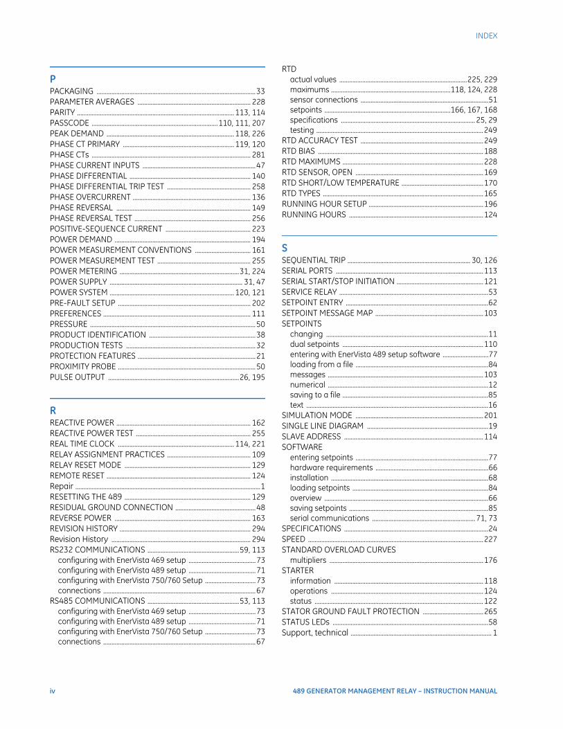
iv 489 GENERATOR MANAGEMENT RELAY – INSTRUCTION MANUAL
INDEX
PPACKAGING .................................................................................................33PARAMETER AVERAGES ..................................................................... 228PARITY ................................................................................................ 113, 114PASSCODE .............................................................................110, 111, 207PEAK DEMAND .............................................................................. 118, 226PHASE CT PRIMARY .................................................................... 119, 120PHASE CTs ................................................................................................. 281PHASE CURRENT INPUTS .....................................................................47PHASE DIFFERENTIAL .......................................................................... 140PHASE DIFFERENTIAL TRIP TEST ................................................... 258PHASE OVERCURRENT ........................................................................ 136PHASE REVERSAL .................................................................................. 149PHASE REVERSAL TEST ....................................................................... 256POSITIVE-SEQUENCE CURRENT .................................................... 223POWER DEMAND ................................................................................... 194POWER MEASUREMENT CONVENTIONS .................................. 161POWER MEASUREMENT TEST ......................................................... 255POWER METERING .........................................................................31, 224POWER SUPPLY ................................................................................. 31, 47POWER SYSTEM ............................................................................ 120, 121PRE-FAULT SETUP ................................................................................. 202PREFERENCES .......................................................................................... 111PRESSURE .....................................................................................................50PRODUCT IDENTIFICATION .................................................................38PRODUCTION TESTS ...............................................................................32PROTECTION FEATURES ........................................................................21PROXIMITY PROBE ....................................................................................50PULSE OUTPUT ................................................................................26, 195
RREACTIVE POWER .................................................................................. 162REACTIVE POWER TEST ...................................................................... 255REAL TIME CLOCK ....................................................................... 114, 221RELAY ASSIGNMENT PRACTICES ................................................... 109RELAY RESET MODE ............................................................................. 129REMOTE RESET ........................................................................................ 124Repair .................................................................................................................1RESETTING THE 489 ............................................................................. 129RESIDUAL GROUND CONNECTION .................................................48REVERSE POWER ................................................................................... 163REVISION HISTORY ................................................................................ 294Revision History ..................................................................................... 294RS232 COMMUNICATIONS ........................................................59, 113
configuring with EnerVista 469 setup .........................................73configuring with EnerVista 489 setup .........................................71configuring with EnerVista 750/760 Setup ...............................73connections .............................................................................................67
RS485 COMMUNICATIONS ........................................................53, 113configuring with EnerVista 469 setup .........................................73configuring with EnerVista 489 setup .........................................71configuring with EnerVista 750/760 Setup ...............................73connections .............................................................................................67
RTDactual values ..............................................................................225, 229maximums .........................................................................118, 124, 228sensor connections ..............................................................................51setpoints .............................................................................166, 167, 168specifications .................................................................................. 25, 29testing ......................................................................................................249
RTD ACCURACY TEST ...........................................................................249RTD BIAS .....................................................................................................188RTD MAXIMUMS ......................................................................................228RTD SENSOR, OPEN ..............................................................................169RTD SHORT/LOW TEMPERATURE ..................................................170RTD TYPES ..................................................................................................165RUNNING HOUR SETUP ......................................................................196RUNNING HOURS ..................................................................................124
SSEQUENTIAL TRIP ........................................................................... 30, 126SERIAL PORTS ..........................................................................................113SERIAL START/STOP INITIATION .....................................................121SERVICE RELAY ...........................................................................................53SETPOINT ENTRY .......................................................................................62SETPOINT MESSAGE MAP ..................................................................103SETPOINTS
changing ...................................................................................................11dual setpoints ......................................................................................110entering with EnerVista 489 setup software ............................77loading from a file .................................................................................84messages ...............................................................................................103numerical ..................................................................................................12saving to a file .........................................................................................85text ...............................................................................................................16
SIMULATION MODE ..............................................................................201SINGLE LINE DIAGRAM ..........................................................................19SLAVE ADDRESS .....................................................................................114SOFTWARE
entering setpoints .................................................................................77hardware requirements .....................................................................66installation ................................................................................................68loading setpoints ...................................................................................84overview ....................................................................................................66saving setpoints .....................................................................................85serial communications ............................................................... 71, 73
SPECIFICATIONS ........................................................................................24SPEED ...........................................................................................................227STANDARD OVERLOAD CURVES
multipliers ..............................................................................................176STARTER
information ...........................................................................................118operations .............................................................................................124status .......................................................................................................122
STATOR GROUND FAULT PROTECTION .....................................265STATUS LEDs ...............................................................................................58Support, technical ...................................................................................... 1
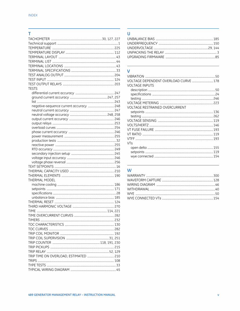
INDEX
489 GENERATOR MANAGEMENT RELAY – INSTRUCTION MANUAL v
TTACHOMETER .........................................................................30, 127, 227Technical support .......................................................................................1TEMPERATURE ........................................................................................ 225TEMPERATURE DISPLAY ..................................................................... 112TERMINAL LAYOUT .................................................................................. 43TERMINAL LIST ........................................................................................... 44TERMINAL LOCATIONS .......................................................................... 43TERMINAL SPECIFICATIONS ................................................................ 33TEST ANALOG OUTPUT ....................................................................... 204TEST INPUT ................................................................................................ 124TEST OUTPUT RELAYS ......................................................................... 203TESTS
differential current accuracy ....................................................... 247ground current accuracy ..................................................... 247, 257list .............................................................................................................. 243negative-sequence current accuracy ..................................... 248neutral current accuracy ............................................................... 247neutral voltage accuracy ..................................................... 248, 258output current accuracy ................................................................ 246output relays ........................................................................................ 253overload curves .................................................................................. 254phase current accuracy ................................................................. 246power measurement ....................................................................... 255production tests .................................................................................... 32reactive power .................................................................................... 255RTD accuracy ....................................................................................... 249secondary injection setup ............................................................. 245voltage input accuracy ................................................................... 246voltage phase reversal .................................................................... 256
TEXT SETPOINTS ........................................................................................ 16THERMAL CAPACITY USED ............................................................... 210THERMAL ELEMENTS ........................................................................... 190THERMAL MODEL
machine cooling ................................................................................. 186setpoints ................................................................................................ 171specifications .......................................................................................... 28unbalance bias ................................................................................... 185
THERMAL RESET ..................................................................................... 124THIRD HARMONIC VOLTAGE ........................................................... 270TIME .................................................................................................... 114, 221TIME OVERCURRENT CURVES ......................................................... 282TIMERS ......................................................................................................... 232TOC CHARACTERISTICS ...................................................................... 130TOC CURVES ............................................................................................. 282TRIP COIL MONITOR ............................................................................. 192TRIP COIL SUPERVISION .............................................................31, 251TRIP COUNTER ....................................................................118, 191, 230TRIP PICKUPS ........................................................................................... 215TRIP RELAY .........................................................................................52, 129TRIP TIME ON OVERLOAD, ESTIMATED ...................................... 210TRIPS ............................................................................................................. 108TYPE TESTS ................................................................................................... 33TYPICAL WIRING DIAGRAM ................................................................. 45
UUNBALANCE BIAS ..................................................................................185UNDERFREQUENCY ..............................................................................150UNDERVOLTAGE ..............................................................................29, 144UNPACKING THE RELAY .......................................................................... 3UPGRADING FIRMWARE .......................................................................85
VVIBRATION ....................................................................................................50VOLTAGE DEPENDENT OVERLOAD CURVE ..............................178VOLTAGE INPUTS
description ................................................................................................50specifications ..........................................................................................24testing ......................................................................................................246
VOLTAGE METERING ............................................................................223VOLTAGE RESTRAINED OVERCURRENT
setpoints .................................................................................................136testing ......................................................................................................262
VOLTAGE SENSING ...............................................................................119VOLTS/HERTZ ...........................................................................................146VT FUSE FAILURE ...................................................................................193VT RATIO .....................................................................................................119VTFF ...............................................................................................................193VTs
open delta ..............................................................................................155setpoints .................................................................................................119wye connected ....................................................................................154
WWARRANTY ................................................................................................300WAVEFORM CAPTURE .........................................................................128WIRING DIAGRAM ....................................................................................46WITHDRAWAL .............................................................................................40WYE ..................................................................................................................50WYE CONNECTED VTs .........................................................................154

vi 489 GENERATOR MANAGEMENT RELAY – INSTRUCTION MANUAL
INDEX