Embed Size (px)
Citation preview
40:1 QS Pump System
Customer Product ManualPart 334 452A
NORDSON CORPORATION D AMHERST, OHIO D USA
E 2000 Nordson CorporationAll rights reserved
334 452AIssued 11/00
Manual 24-14
Nordson Corporation welcomes requests for information, comments and inquiries about its products. Generalinformation about Nordson can be found on the Internet using the following address: http://www.nordson.com.
Address all correspondence to:
Nordson CorporationAttn: Customer Service555 Jackson StreetAmherst, OH 44001
Notice
This is a Nordson Corporation publication which is protected by copyright. Original copyright date 2000.No part of this document may be photocopied, reproduced, or translated to another language without the prior writtenconsent of Nordson Corporation. The information contained in this publication is subject to change without notice.
Trademarks
AccuJet, AquaGuard, Asymtek, Automove, Autotech, Blue Box, CF, CanWorks, Century, Clean Coat, CleanSleeve,CleanSpray, Compumelt, Control Coat, Cross-Cut, Cyclo-Kinetic, Dispensejet, DispenseMate, Durafiber, Durasystem,Easy Coat, Easymove Plus, Econo-Coat, EPREG, ETI, Excel 2000, Flex-O-Coat, FlexiCoat, Flexi-Spray, Flow Sentry,
Fluidmove, Fluidshooter, FoamMelt, FoamMix, Helix, Horizon, Hose Mole, Hot Shot, Hot Stitch, Isocoil, Isocore, Iso-Flo, JR,KB30, Little Squirt, Magnastatic, MEG, Meltex, MicroSet, Millenium, Mini Squirt, Moist-Cure, Mountaingate, MultiScan,
Nordson, OmniScan, Opticoat, Package of Values, PluraFoam, Porous Coat, PowderGrid, Powderware, Pro-Flo, ProLink,Pro-Meter, Pro-Stream, PRX, RBX, Ready Cost, Rhino, S. design stylized, Saturn, SC5, SCF, Select Charge, Select Coat,Select Cure, Shur-Lok, Slautterback, Smart-Coat, Spray Squirt, Spraymelt, Super Squirt, Sure-Bond, Sure Coat, System
Sentry, Tela-Therm, Trends, Tribomatic, UniScan, UpTime, Veritec, Versa-Coat, Versa-Screen, Versa-Spray, Watermark, andWhen you expect more. are registered trademarks -- -- of Nordson Corporation.
ATS, Auto-Flo, AutoScan, BetterBook, Chameleon, CanNeck, Check Mate, CPX, Control Weave, Controlled Fiberization,EasyClean, Ebraid, Eclipse, EquiBead, Fillmaster, Gluie, Ink-Dot, Maxima, MicroFin, Minimeter, Multifil, OptiMix,
Pattern View, PluraMix, Primarc, Prism, Process Sentry, PurTech, Pulse Spray, Seal Sentry, Select Series, Sensomatic,Shaftshield, Spectral, Spectrum, Sure Brand, Swirl Coat, Vista, Walcom, and 2 Rings (Design)
are trademarks -- T -- of Nordson Corporation.
All other trademarks are the property of their respective owners.
Table of Contents i
� 2000 Nordson CorporationAll rights reserved
334 452AIssued 11/00
Manual 24-14
Table of Contents
1. Safety 1. . . . . . . . . . . . . . . . . . . . . . . . . . . . . . . . . . . . . . . . . . . . . . . . . . . . .
Qualified Personnel 1. . . . . . . . . . . . . . . . . . . . . . . . . . . . . . . . . . . . . . .
Intended Use 1. . . . . . . . . . . . . . . . . . . . . . . . . . . . . . . . . . . . . . . . . . . . .
Regulations and Approvals 1. . . . . . . . . . . . . . . . . . . . . . . . . . . . . . . . .
Personal Safety 2. . . . . . . . . . . . . . . . . . . . . . . . . . . . . . . . . . . . . . . . . . .
High-Pressure Fluids 3. . . . . . . . . . . . . . . . . . . . . . . . . . . . . . . . . . . .
Fire Safety 4. . . . . . . . . . . . . . . . . . . . . . . . . . . . . . . . . . . . . . . . . . . . . . .
Halogenated Hydrocarbon Solvent Hazards 5. . . . . . . . . . . . . . . .
Action in the Event of a Malfunction 5. . . . . . . . . . . . . . . . . . . . . . . . .
Disposal 5. . . . . . . . . . . . . . . . . . . . . . . . . . . . . . . . . . . . . . . . . . . . . . . . .
2. Description 6. . . . . . . . . . . . . . . . . . . . . . . . . . . . . . . . . . . . . . . . . . . . . . . . .
Pump 8. . . . . . . . . . . . . . . . . . . . . . . . . . . . . . . . . . . . . . . . . . . . . . . . . . .
Air Motor 8. . . . . . . . . . . . . . . . . . . . . . . . . . . . . . . . . . . . . . . . . . . . . . . . .
Rams 9. . . . . . . . . . . . . . . . . . . . . . . . . . . . . . . . . . . . . . . . . . . . . . . . . . .
200-Liter Dual Post Ram 9. . . . . . . . . . . . . . . . . . . . . . . . . . . . . . . .
20-Liter Dual Post Ram 9. . . . . . . . . . . . . . . . . . . . . . . . . . . . . . . . .
20-Liter Single Post Ram 9. . . . . . . . . . . . . . . . . . . . . . . . . . . . . . . .
Theory of Operation 9. . . . . . . . . . . . . . . . . . . . . . . . . . . . . . . . . . . . . . .
3. Installation 10. . . . . . . . . . . . . . . . . . . . . . . . . . . . . . . . . . . . . . . . . . . . . . . .
Ram Setup 11. . . . . . . . . . . . . . . . . . . . . . . . . . . . . . . . . . . . . . . . . . . . . .
4. Operation 12. . . . . . . . . . . . . . . . . . . . . . . . . . . . . . . . . . . . . . . . . . . . . . . . .
Ram Movement 12. . . . . . . . . . . . . . . . . . . . . . . . . . . . . . . . . . . . . . . . . .
Loading a New Material Container 12. . . . . . . . . . . . . . . . . . . . . . . . .
Ram Operation 13. . . . . . . . . . . . . . . . . . . . . . . . . . . . . . . . . . . . . . . . . .
5. Maintenance 14. . . . . . . . . . . . . . . . . . . . . . . . . . . . . . . . . . . . . . . . . . . . . . .
Long-Term Shut Down 15. . . . . . . . . . . . . . . . . . . . . . . . . . . . . . . . . . . .
Flushing the System 15. . . . . . . . . . . . . . . . . . . . . . . . . . . . . . . . . . .
Table of Contentsii
� 2000 Nordson CorporationAll rights reserved
334 452AIssued 11/00
Manual 24-14
6. Troubleshooting 16. . . . . . . . . . . . . . . . . . . . . . . . . . . . . . . . . . . . . . . . . . . .
Pump 16. . . . . . . . . . . . . . . . . . . . . . . . . . . . . . . . . . . . . . . . . . . . . . . . . .
Air Motor 18. . . . . . . . . . . . . . . . . . . . . . . . . . . . . . . . . . . . . . . . . . . . . . . .
Air Motor Icing 19. . . . . . . . . . . . . . . . . . . . . . . . . . . . . . . . . . . . . . . . . . .
Ram 20. . . . . . . . . . . . . . . . . . . . . . . . . . . . . . . . . . . . . . . . . . . . . . . . . . .
7. Repair 21. . . . . . . . . . . . . . . . . . . . . . . . . . . . . . . . . . . . . . . . . . . . . . . . . . . .
Pressure Relief 21. . . . . . . . . . . . . . . . . . . . . . . . . . . . . . . . . . . . . . . . . .
Air Motor Disassembly 22. . . . . . . . . . . . . . . . . . . . . . . . . . . . . . . . . . . .
Removing the Air Motor from the Ram 22. . . . . . . . . . . . . . . . . . . .
Disassembling the Housing 22. . . . . . . . . . . . . . . . . . . . . . . . . . . . .
Disassembling the Air Motor Base 23. . . . . . . . . . . . . . . . . . . . . . .
Final Disassembly 23. . . . . . . . . . . . . . . . . . . . . . . . . . . . . . . . . . . . .
Air Motor Assembly 24. . . . . . . . . . . . . . . . . . . . . . . . . . . . . . . . . . . . . .
Assembling the Air Motor Base 24. . . . . . . . . . . . . . . . . . . . . . . . . .
Assembling the Housing 25. . . . . . . . . . . . . . . . . . . . . . . . . . . . . . . .
Mounting the Air Motor 25. . . . . . . . . . . . . . . . . . . . . . . . . . . . . . . . .
Pump Disassembly 26. . . . . . . . . . . . . . . . . . . . . . . . . . . . . . . . . . . . . . .
Removing the Pump from the Air Motor 26. . . . . . . . . . . . . . . . . . .
Final Disassembly 26. . . . . . . . . . . . . . . . . . . . . . . . . . . . . . . . . . . . .
Pump Assembly 27. . . . . . . . . . . . . . . . . . . . . . . . . . . . . . . . . . . . . . . . .
Assembling the Pump Housing 27. . . . . . . . . . . . . . . . . . . . . . . . . .
Final Pump Assembly 28. . . . . . . . . . . . . . . . . . . . . . . . . . . . . . . . . .
Ram Piston Rod Packing Disassembly 29. . . . . . . . . . . . . . . . . . . . .
Ram Piston Rod Packing Assembly 29. . . . . . . . . . . . . . . . . . . . . . . .
Ram Piston Disassembly 30. . . . . . . . . . . . . . . . . . . . . . . . . . . . . . . . .
Ram Piston Assembly and Installation 30. . . . . . . . . . . . . . . . . . . . . .
Table of Contents iii
� 2000 Nordson CorporationAll rights reserved
334 452AIssued 11/00
Manual 24-14
8. Parts 31. . . . . . . . . . . . . . . . . . . . . . . . . . . . . . . . . . . . . . . . . . . . . . . . . . . . .
Using the Illustrated Parts List 31. . . . . . . . . . . . . . . . . . . . . . . . . . . . .
Top Level Assemblies 32. . . . . . . . . . . . . . . . . . . . . . . . . . . . . . . . . . . .
Air Motor 32. . . . . . . . . . . . . . . . . . . . . . . . . . . . . . . . . . . . . . . . . . . . . . . .
Air Motor Repair Kit 36. . . . . . . . . . . . . . . . . . . . . . . . . . . . . . . . . . . .
Pump 37. . . . . . . . . . . . . . . . . . . . . . . . . . . . . . . . . . . . . . . . . . . . . . . . . .
Pump Repair Kit 40. . . . . . . . . . . . . . . . . . . . . . . . . . . . . . . . . . . . . . .
200-Liter Dual Post Ram 41. . . . . . . . . . . . . . . . . . . . . . . . . . . . . . . . . .
200-Liter Dual Post Repair Kit 44. . . . . . . . . . . . . . . . . . . . . . . . . . .
20-Liter Dual Post Ram 45. . . . . . . . . . . . . . . . . . . . . . . . . . . . . . . . . . .
20-Liter Dual Post Repair Kit 47. . . . . . . . . . . . . . . . . . . . . . . . . . . .
Hold Down 48. . . . . . . . . . . . . . . . . . . . . . . . . . . . . . . . . . . . . . . . . . . . . .
Control Box 49. . . . . . . . . . . . . . . . . . . . . . . . . . . . . . . . . . . . . . . . . . . . .
Control Panel 50. . . . . . . . . . . . . . . . . . . . . . . . . . . . . . . . . . . . . . . . . . . .
20-Liter Single Post Ram 51. . . . . . . . . . . . . . . . . . . . . . . . . . . . . . . . .
20-Liter Single Post Repair Kit 54. . . . . . . . . . . . . . . . . . . . . . . . . .
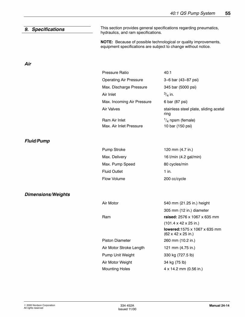
9. Specifications 55. . . . . . . . . . . . . . . . . . . . . . . . . . . . . . . . . . . . . . . . . . . . . .
Air 55. . . . . . . . . . . . . . . . . . . . . . . . . . . . . . . . . . . . . . . . . . . . . . . . . . . . .
Fluid/Pump 55. . . . . . . . . . . . . . . . . . . . . . . . . . . . . . . . . . . . . . . . . . . . . .
Dimensions/Weights 55. . . . . . . . . . . . . . . . . . . . . . . . . . . . . . . . . . . . .
10. Options 56. . . . . . . . . . . . . . . . . . . . . . . . . . . . . . . . . . . . . . . . . . . . . . . . . . .
Electric Automatic Changeover 56. . . . . . . . . . . . . . . . . . . . . . . . . . . .
Low-Level Indicator 56. . . . . . . . . . . . . . . . . . . . . . . . . . . . . . . . . . . .
Hold Down 56. . . . . . . . . . . . . . . . . . . . . . . . . . . . . . . . . . . . . . . . . . . . . .
Control Box 56. . . . . . . . . . . . . . . . . . . . . . . . . . . . . . . . . . . . . . . . . . .
Table of Contentsiv
� 2000 Nordson CorporationAll rights reserved
334 452AIssued 11/00
Manual 24-14
40:1 QS Pump System 1
E 2000 Nordson CorporationAll rights reserved
334 452AIssued 11/00
Manual 24-14
40:1 QS Pump System
Read and follow these safety instructions. Task- and equipment-specificwarnings, cautions, and instructions are included in equipmentdocumentation where appropriate.
Make sure all equipment documentation, including these instructions, isaccessible to persons operating or servicing equipment.
Equipment owners are responsible for making sure that Nordsonequipment is installed, operated, and serviced by qualified personnel.Qualified personnel are those employees or contractors who are trainedto safely perform their assigned tasks. They are familiar with all relevantsafety rules and regulations and are physically capable of performingtheir assigned tasks.
Use of Nordson equipment in ways other than those described in thedocumentation supplied with the equipment may result in injury topersons or damage to property.
Some examples of unintended use of equipment include
S using incompatible materialsS making unauthorized modificationsS removing or bypassing safety guards or interlocksS using incompatible or damaged partsS using unapproved auxiliary equipmentS operating equipment in excess of maximum ratings
Make sure all equipment is rated and approved for the environment inwhich it is used. Any approvals obtained for Nordson equipment will bevoided if instructions for installation, operation, and service are notfollowed.
1. Safety
Qualified Personnel
Intended Use
Regulations and Approvals
40:1 QS Pump System2
E 2000 Nordson CorporationAll rights reserved
334 452AIssued 11/00
Manual 24-14
To prevent injury follow these instructions.
S Do not operate or service equipment unless you are qualified.
S Do not operate equipment unless safety guards, doors, or covers areintact and automatic interlocks are operating properly. Do not bypassor disarm any safety devices.
S Keep clear of moving equipment. Before adjusting or servicingmoving equipment, shut off the power supply and wait until theequipment comes to a complete stop. Lock out power and secure theequipment to prevent unexpected movement.
S Relieve (bleed off) hydraulic and pneumatic pressure before adjustingor servicing pressurized systems or components. Disconnect, lockout, and tag switches before servicing electrical equipment.
S While operating manual spray guns, make sure you are grounded.Wear electrically conductive gloves or a grounding strap connected tothe gun handle or other true earth ground. Do not wear or carrymetallic objects such as jewelry or tools.
S If you receive even a slight electrical shock, shut down all electrical orelectrostatic equipment immediately. Do not restart the equipmentuntil the problem has been identified and corrected.
S Obtain and read Material Safety Data Sheets (MSDS) for all materialsused. Follow the manufacturer’s instructions for safe handling anduse of materials, and use recommended personal protection devices.
S Make sure the spray area is adequately ventilated.
S To prevent injury, be aware of less-obvious dangers in the workplacethat often cannot be completely eliminated, such as hot surfaces,sharp edges, energized electrical circuits, and moving parts thatcannot be enclosed or otherwise guarded for practical reasons.
Personal Safety
40:1 QS Pump System 3
E 2000 Nordson CorporationAll rights reserved
334 452AIssued 11/00
Manual 24-14
High-Pressure Fluids
High-pressure fluids, unless they are safely contained, are extremelyhazardous. Always relieve fluid pressure before adjusting or servicinghigh pressure equipment. A jet of high-pressure fluid can cut like a knifeand cause serious bodily injury, amputation, or death. Fluids penetratingthe skin can also cause toxic poisoning.
If you suffer a fluid injection injury, seek medical care immediately. Ifpossible, provide a copy of the MSDS for the injected fluid to the healthcare provider.
The National Spray Equipment Manufacturers Association has created awallet card that you should carry when you are operating high-pressurespray equipment. These cards are supplied with your equipment. Thefollowing is the text of this card:
WARNING: Any injury caused by high pressure liquid can beserious. If you are injured or even suspect an injury:
S Go to an emergency room immediately.S Tell the doctor that you suspect an injection injury.S Show him this card.S Tell him what kind of material you were spraying.
MEDICAL ALERT—AIRLESS SPRAY WOUNDS: NOTE TO PHYSICIAN
Injection in the skin is a serious traumatic injury. It is important to treatthe injury surgically as soon as possible. Do not delay treatment toresearch toxicity. Toxicity is a concern with some exotic coatings injecteddirectly into the bloodstream.
Consultation with a plastic surgeon or a reconstructive hand surgeon maybe advisable.
The seriousness of the wound depends on where the injury is on thebody, whether the substance hit something on its way in and deflectedcausing more damage, and many other variables including skinmicroflora residing in the paint or gun which are blasted into the wound.If the injected paint contains acrylic latex and titanium dioxide thatdamage the tissue’s resistance to infection, bacterial growth will flourish.The treatment that doctors recommend for an injection injury to the handincludes immediate decompression of the closed vascular compartmentsof the hand to release the underlying tissue distended by the injectedpaint, judicious wound debridement, and immediate antibiotic treatment.
40:1 QS Pump System4
E 2000 Nordson CorporationAll rights reserved
334 452AIssued 11/00
Manual 24-14
To avoid a fire or explosion, follow these instructions.
S Ground all conductive equipment in the spray area. Use onlygrounded air and fluid hoses. Check equipment and workpiecegrounding devices regularly. Resistance to ground must not exceedone megohm.
S Shut down all equipment immediately if you notice static sparking orarcing. Do not restart the equipment until the cause has beenidentified and corrected.
S Do not smoke, weld, grind, or use open flames where flammablematerials are being used or stored.
S Do not heat materials to temperatures above those recommended bythe manufacturer. Make sure heat monitoring and limiting devices areworking properly.
S Provide adequate ventilation to prevent dangerous concentrations ofvolatile particles or vapors. Refer to local codes or your materialMSDS for guidance.
S Do not disconnect live electrical circuits while working with flammablematerials. Shut off power at a disconnect switch first to preventsparking.
S Know where emergency stop buttons, shutoff valves, and fireextinguishers are located. If a fire starts in a spray booth,immediately shut off the spray system and exhaust fans.
S Shut off electrostatic power and ground the charging system beforeadjusting, cleaning, or repairing electrostatic equipment.
S Clean, maintain, test, and repair equipment according to theinstructions in your equipment documentation.
S Use only replacement parts that are designed for use with originalequipment. Contact your Nordson representative for partsinformation and advice.
Fire Safety
40:1 QS Pump System 5
E 2000 Nordson CorporationAll rights reserved
334 452AIssued 11/00
Manual 24-14
Halogenated Hydrocarbon Solvent Hazards
Do not use halogenated hydrocarbon solvents in a pressurized systemthat contains aluminum components. Under pressure, these solventscan react with aluminum and explode, causing injury, death, or propertydamage. Halogenated hydrocarbon solvents contain one or more of thefollowing elements:
Element Symbol Prefix
Fluorine F “Fluoro-”
Chlorine Cl “Chloro-”
Bromine Br “Bromo-”
Iodine I “Iodo-”
Check your material MSDS or contact your material supplier for moreinformation. If you must use halogenated hydrocarbon solvents, contactyour Nordson representative for information about compatible Nordsoncomponents.
If a system or any equipment in a system malfunctions, shut off thesystem immediately and perform the following steps:
S Disconnect and lock out system electrical power. Close hydraulic andpneumatic shutoff valves and relieve pressures.
S Identify the reason for the malfunction and correct it before restartingthe system.
Dispose of equipment and materials used in operation and servicingaccording to local codes.
Action in the Event of aMalfunction
Disposal
40:1 QS Pump System6
E 2000 Nordson CorporationAll rights reserved
334 452AIssued 11/00
Manual 24-14
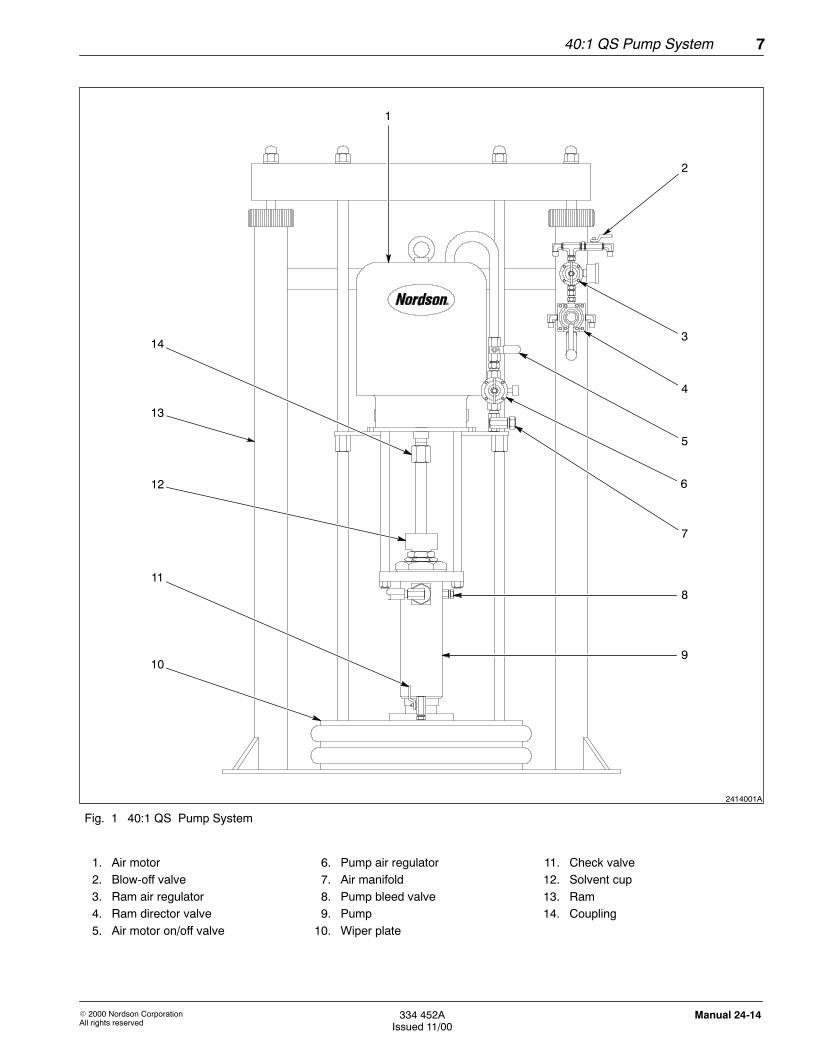
The 40:1 QS pump system delivers Nordson-approved adhesives andsealant materials at room temperature from 20-liter pails and 200-literdrums according to your specific system configuration.
See Figure 1.
The three available systems are distinguished by their ramconfigurations:
S 200-liter dual postS 20-liter dual postS 20-liter single post
The pump system has pneumatic operating controls and includes apump (9), an air motor (1), a single or dual post ram (13), and allnecessary pneumatic filters, and valves.
20-liter systems can be equipped with an optional pneumatic pail holddown. Refer to the Options section for more information.
2. Description
40:1 QS Pump System 7
E 2000 Nordson CorporationAll rights reserved
334 452AIssued 11/00
Manual 24-14
2
2414001A
13
1
3
4
5
6
7
8
910
11
12
14
Fig. 1 40:1 QS Pump System
1. Air motor2. Blow-off valve3. Ram air regulator4. Ram director valve5. Air motor on/off valve
6. Pump air regulator7. Air manifold8. Pump bleed valve9. Pump10. Wiper plate
11. Check valve12. Solvent cup13. Ram14. Coupling
40:1 QS Pump System8
E 2000 Nordson CorporationAll rights reserved
334 452AIssued 11/00
Manual 24-14
See Figure 1.
The dual-acting pump (9) is air-operated, featuring positive displacementand demand-type operation. The pump delivers a constant supply ofmaterial to dispensing devices or process applicators. The pump shaftconnects to the air motor shaft via a coupling (14). A wiper plate (10) orpail disk attaches to the lower end of the pump.
The 200-liter dual post configurations include a wiper plate with wipers.The 20-liter dual and single post configurations include a small-diameterwiper blade, referred to as a pail disk. Refer to the Parts section for moreinformation.
CAUTION: If the material is too abrasive or not compatible,equipment may wear out prematurely and components may bedamaged.
The pump handles high-viscosity materials as well as certain abrasivematerials. Contact your Nordson Corporation representative to makesure the material you wish to pump is compatible with your equipmentand your components.
NOTE: Contact your Nordson representative for hose specifications andordering details.
WARNING: The moving air motor piston can pinch or amputatefingers. Keep clear of all moving parts when starting oroperating the air motor.
See Figure 1.
All 40:1 QS pump system configurations include an air motor (1) thatdelivers a 40:1 pump ratio. The air motor mounts to the ram (13) abovethe pump (9). The coupling (14) connects the air motor shaft with thepump shaft.
Pump
Air Motor
40:1 QS Pump System 9
E 2000 Nordson CorporationAll rights reserved
334 452AIssued 11/00
Manual 24-14
See Figure 1.
The ram (13) represents a two piston elevator frame that lifts the pumpassembly and the air motor.
Some of the listed components might not apply to your system,depending on your specific ram configuration.
200-Liter Dual Post Ram
See Figure 4.
The 200-liter dual post ram delivers material from a 200-liter drum. Theram has dual pistons, controlled by a 3-position air regulator.
20-Liter Dual Post Ram
See Figure 5.
The 20-liter dual post ram delivers material from a 20 liter drum. The ramincludes dual pistons. As an option, a pail hold down is available toprevent lifting up the 20-liter pail while raising the pail disk.
20-Liter Single Post Ram
See Figure 6.
The 20-liter single post ram is designed to fit into smaller spaces. Theram includes a single piston.
Ram cylinders lower the air-operated piston pump into the material drum.The rubber wipers around the outer edge of the wiper plate create asealed compartment below the wiper plate.
The downward movement of the wiper plate forces material into thepump. The operator turns on the air pressure to the air motor, the pumpstrokes, and material is delivered to the dispensing device.
When the drum is empty, the operator raises the wiper plate, replaces theempty drum with a full one, and lowers the wiper plate back into the newdrum.
Rams
Theory of Operation
40:1 QS Pump System10
E 2000 Nordson CorporationAll rights reserved
334 452AIssued 11/00
Manual 24-14
The 40:1 QS pump system is shipped pre-assembled, bolted to a pallet,and crated or covered with a shipping carton. A Nordson representativemust be present during the installation.
WARNING: Allow only qualified personnel to perform thefollowing tasks. Follow the safety instructions in this documentand all other related documentation.
WARNING: A pressurized pump is considered active even if itis not pumping. Only a pump not under pressure from the airsupply is considered inactive.
WARNING: Comply with all applicable local, state, and nationalfire, electrical, and safety regulations.
CAUTION: Do not lift the equipment by the air motor lift ring ifthe total weight of the equipment exceeds 250 kg (550 lb).
3. Installation
40:1 QS Pump System 11
E 2000 Nordson CorporationAll rights reserved
334 452AIssued 11/00
Manual 24-14
See Figure 1.
Position the ram (13) so the pump air regulators (6) are easily accessible.Provide sufficient overhead clearance when the ram is fully raised. Referto the Specifications section for dimensions.
1. Using the holes in the ram base as a guide, drill holes and install13-mm (0.5-in.) anchors.
2. Level the ram in all directions. Use shims, if necessary.
3. Connect the house air line to the air input connector.
4. Set the pump air regulator and the ram air regulator (3) to 0. Makesure that the blow-off valve (2) is closed.
CAUTION: Use a hose support to prevent hose damage inapplications where an overhead tool balancer or similar devicesuspends the hose. Route the hose to prevent kinking andabrasion.
CAUTION: Do not bend hoses sharper than 15 cm (6 in.)minimum bend radius diameter and do not use hoses to pull theequipment. You may damage the hoses.
5. Connect the air and fluid hoses.
6. Connect the spray device or dispensing valve. Connect componentsto a properly grounded fluid hose and pump.
7. Fill the solvent cup (12) with compatible fluid.
8. If applicable, install and secure system guards.
Ram Setup
40:1 QS Pump System12
E 2000 Nordson CorporationAll rights reserved
334 452AIssued 11/00
Manual 24-14
Perform these steps to prepare and operate the 40:1 QS pump system.
WARNING: Allow only qualified personnel to perform thefollowing tasks. Follow the safety instructions in this documentand all other related documentation.
WARNING: Do not operate the air motor without the shield inplace. Pinching or amputation of fingers or hands may occur.
CAUTION: Do not use a damaged container. It may damagethe wiper plate or pail disk when lowered into the container.
See Figure 1.
The ram director valve controls the ram movement.
1. Turn the ram director valve (4) to NEUTRAL to stop the movement ofthe wiper plate (10).
2. Turn the ram director valve UP to raise the wiper plate.
See Figure 1.
Inspect the new material container for dents or other damage beforeinstalling.
1. Coat the wipers or pail seals with dispensing material compatibleO-ring grease.
2. Place a new material container on the pump base and center thecontainer underneath the wiper plate (10).
WARNING: Do not lower the wiper plate into the containerwithout wearing goggles, gloves, and long sleeved protectiveclothing. Air expelled when bleeding air from the system maycontain material that causes injury.
3. Open the check valve (11) and turn the ram director valve (4) DOWNto lower the wiper plate into the open container until material beginsto flow from the check valve.
4. Turn the ram director valve to NEUTRAL and close the check valve.
5. Turn the ram director valve DOWN to force material into thepump (9).
4. Operation
Ram Movement
Loading a New MaterialContainer
40:1 QS Pump System 13
E 2000 Nordson CorporationAll rights reserved
334 452AIssued 11/00
Manual 24-14
NOTE: Make sure hoses and dispensing devices are secured firmly andthat the dispensing devices are not pointing away from people.
6. Open the pump bleed valve (8) to purge the remaining air.
7. Close the pump bleed valve.
WARNING: Do not open the pump bleed valve more than fourturns. The bleed valve and material may be forced from thevalve body if loosened more than four turns. Personal injurycould result.
8. Adjust the pump air regulator (6) to increase pressure until the airmotor (1) begins to operate.
NOTE: If the air motor ices up, make sure a vertical loop in the air linedrop hose from the main air supply line is installed.
NOTE: Do not increase the pressure beyond the minimum required tocycle the pump.
See Figure 1.
Perform the following steps to operate the ram:
1. Close the ram air regulator (3) and the blow-off valve (2).
2. Open the remotely located main air valve and set the ram airregulator to 4 bar (58 psi).
3. Turn the ram director valve (4) to UP and let the ram rise to its fullheight.
WARNING: Do not use damaged material containers. Roughbung openings or large dents may damage the wiper plate andseals, resulting in a runaway pump.
4. Turn the ram director valve to DOWN to lower the wiper plate (10)into the newly installed material container.
5. Turn the ram director valve to NEUTRAL to stop the wiper plate justabove the container rim.
6. Reposition the container if necessary and open the check valve (11)on the wiper plate.
7. Turn the ram director valve to DOWN to lower the wiper plate into thenew container.
8. When material exits the check valve, stop the ram by turning the ramdirector valve to NEUTRAL. Close the check valve and the pump airregulator (6).
Ram Operation
40:1 QS Pump System14
E 2000 Nordson CorporationAll rights reserved
334 452AIssued 11/00
Manual 24-14
9. Set the ram air regulator to 3.5 bar (50 psi) and turn the ram directorvalve to DOWN.
10. Start the pump while leaving the ram director valve in the DOWNposition.
Refer to Table 1 for recommended preventive maintenance procedures.The frequency of periodic system cleaning depends on operatingconditions and shop environment.
WARNING: Allow only qualified personnel to perform thefollowing tasks. Follow the safety instructions in this documentand all other related documentation.
WARNING: To prevent injury, always relief system pressurebefore servicing the equipment. Trigger all dispensing devicesand bleed system pressure.
Table 1 Preventive Maintenance Procedures
Frequency Component Maintenance Task
Daily Entire system Visually inspect before every shift.
Hydraulic and pneumatic components Check connections and tighten if necessary. Inspecttubing for bends or kinks; replace if necessary.
Solvent cup Check fluid level; add compatible solvent if necessary.
Weekly Wipers Check wipers for damage or signs of excessive materialleakage. Remove material around the wipers.
Wiper plate Remove material accumulating on top of the wiper plate.
Pump air regulator Check setting and adjust air pressure if necessary.
Ram air regulator Check setting and adjust air pressure if necessary.
Pump Inspect for leaks, replace pump packing if necessary.
Ram Operation (contd)
5. Maintenance
40:1 QS Pump System 15
E 2000 Nordson CorporationAll rights reserved
334 452AIssued 11/00
Manual 24-14
See Figure 1.
Perform these steps to shut down the 40:1 pump system for longer thana day:
WARNING: Do not lower the wiper plate into the containerwithout wearing goggles, gloves, and long sleeved protectiveclothing. The air expelled when you bleed air from under thewiper plate may contain material that could cause injury.
WARNING: Severe personal injury could result if your hands orfingers are caught between the wiper plate and container. Keepclear of this area.
1. Remove the wiper plate (10) from the material container. Refer to theOperation section for more information.
2. Note the pump air regulator (6) setting. Reduce the pressure so theair motor operates slower with the solvent.
3. Note the ram air regulator (3) setting. Reduce the pressure to1--2 bar (15--30 psi) for this procedure.
Flushing the System
See Figure 1.
Follow these steps to flush the system:
1. Carefully inspect the solvent container for dents or other damage.
2. Center the container under the wiper plate (10). Lower the wiperplate into the container.
3. When the pump (9) starts pumping, slowly increase the air pressureto the air motor (1) until the desired flush rate is obtained.
NOTE: To maintain grounding continuity when flushing or relievingpressure, hold a metal part of the dispensing device firmly to the side of agrounded metal pail.
4. Trigger the dispensing device and hold it downward into an emptywaste container to limit solvent over spray.
5. Pump solvent through the system until no traces of material arevisible in the hose discharge.
6. Remove the solvent container and replace it with a new materialcontainer. Refer to the Operation section for more information.
Long-Term Shut Down
40:1 QS Pump System16
E 2000 Nordson CorporationAll rights reserved
334 452AIssued 11/00
Manual 24-14
WARNING: Allow only qualified personnel to perform thefollowing tasks. Follow the safety instructions in this documentand all other related documentation.
This section contains troubleshooting procedures. These procedurescover only the most common problems that you may encounter. If youcannot solve the problem with the information given here, contact yourlocal Nordson representative for help.
The following table provides descriptions for common pump problems,and suggests corrective actions to solve the problem.
Problem Possible Cause Corrective Action
1. Pump fails to operate Restricted line or low air pressure Clear line and adjust air pressure. Referto Specifications section for operating airpressure information.
Closed or clogged air valves Clear closed or clogged air valves.
Obstructed fluid hose or spray device Clear hose or spray device.
Material dried on the displacementrod
Remove dried material. Refer to theRepair section for more information.
Dirty or worn air motor parts Clean air motor parts.
Air motor icing Reduce air line moisture content. Installa vertical loop in the air line drop hosefrom the main air supply line.
2. Low pump output onboth strokes
Restricted line or low air pressure Clear line and adjust air pressure. Referto Specifications section for operating airpressure information.
Closed or clogged air valves. Clear closed or clogged air valves.
Obstructed fluid hose or spray device Clear hose or spray device.
Bleeder valve open Close bleeder valve.
Worn throat packing in displacementpump
Replace the gland and the packingstack.
Air motor icing Reduce air line moisture content. Installa vertical loop in the air line drop hosefrom the main air supply line.
Continued on next page
6. Troubleshooting
Pump
40:1 QS Pump System 17
E 2000 Nordson CorporationAll rights reserved
334 452AIssued 11/00
Manual 24-14
Problem Possible Cause Corrective Action
3. Low pump output ondown stroke
Held open or worn piston valve orpacking
Clear piston valve and replace the glandand the packing stack.
Air motor icing Reduce air line moisture content. Installa vertical loop in the air line drop hosefrom the main air supply line.
4. Low pump output on upstroke
Held open or worn piston valve orpacking
Clear piston valve and replace the glandand the packing stack.
Air motor icing Reduce air line moisture content. Installa vertical loop in the air line drop hosefrom the main air supply line.
5. Erratic or acceleratedpump speed
Exhausted fluid supply Refill and prime the system.
Held open or worn piston valve orpacking
Clear piston valve and replace the glandand the packing stack.
Held open or worn priming piston Clear priming piston and service thepiston.
Worn throat packing in displacementpump
Replace the gland and the packingstack.
Air motor icing Reduce air line moisture content. Installa vertical loop in the air line drop hosefrom the main air supply line.
40:1 QS Pump System18
E 2000 Nordson CorporationAll rights reserved
334 452AIssued 11/00
Manual 24-14
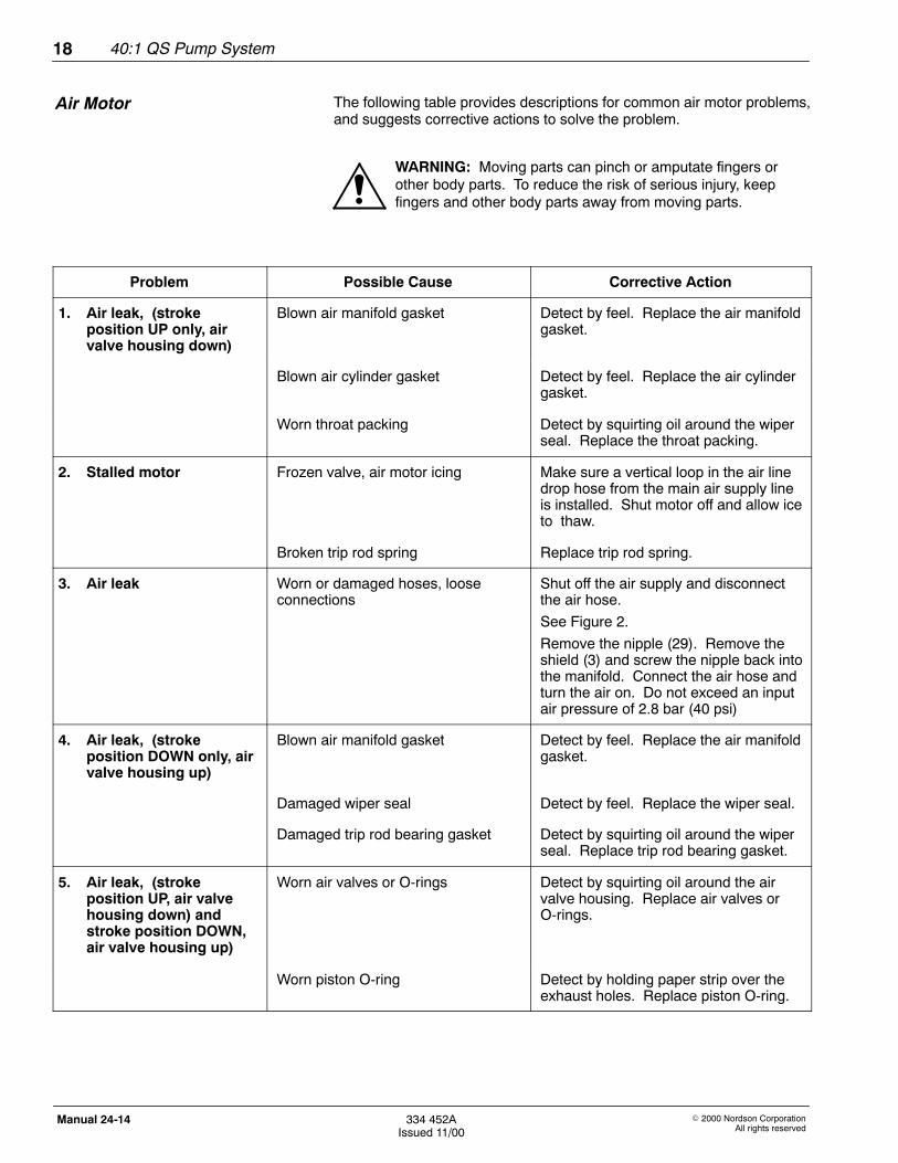
The following table provides descriptions for common air motor problems,and suggests corrective actions to solve the problem.
WARNING: Moving parts can pinch or amputate fingers orother body parts. To reduce the risk of serious injury, keepfingers and other body parts away from moving parts.
Problem Possible Cause Corrective Action
1. Air leak, (strokeposition UP only, airvalve housing down)
Blown air manifold gasket Detect by feel. Replace the air manifoldgasket.
Blown air cylinder gasket Detect by feel. Replace the air cylindergasket.
Worn throat packing Detect by squirting oil around the wiperseal. Replace the throat packing.
2. Stalled motor Frozen valve, air motor icing Make sure a vertical loop in the air linedrop hose from the main air supply lineis installed. Shut motor off and allow iceto thaw.
Broken trip rod spring Replace trip rod spring.
3. Air leak Worn or damaged hoses, looseconnections
Shut off the air supply and disconnectthe air hose.
See Figure 2.
Remove the nipple (29). Remove theshield (3) and screw the nipple back intothe manifold. Connect the air hose andturn the air on. Do not exceed an inputair pressure of 2.8 bar (40 psi)
4. Air leak, (strokeposition DOWN only, airvalve housing up)
Blown air manifold gasket Detect by feel. Replace the air manifoldgasket.
Damaged wiper seal Detect by feel. Replace the wiper seal.
Damaged trip rod bearing gasket Detect by squirting oil around the wiperseal. Replace trip rod bearing gasket.
5. Air leak, (strokeposition UP, air valvehousing down) andstroke position DOWN,air valve housing up)
Worn air valves or O-rings Detect by squirting oil around the airvalve housing. Replace air valves orO-rings.
Worn piston O-ring Detect by holding paper strip over theexhaust holes. Replace piston O-ring.
Air Motor
40:1 QS Pump System 19
E 2000 Nordson CorporationAll rights reserved
334 452AIssued 11/00
Manual 24-14
Moisture in the compressed air can collect in the air motor and freeze,causing the motor to stall.
If icing occurs, shut off the air supply and allow the ice to thaw. Tominimize icing, reduce the moisture in your compressed air supply byusing an air dryer or filter that traps water.
The main air line should slope slightly downward so that water will collectat the end of the line where it can be drained. In addition, plumb a dropline from the top of each main air line. Install an automatic drain or drainvalve at the bottom of each drop.
Air Motor Icing
40:1 QS Pump System20
E 2000 Nordson CorporationAll rights reserved
334 452AIssued 11/00
Manual 24-14
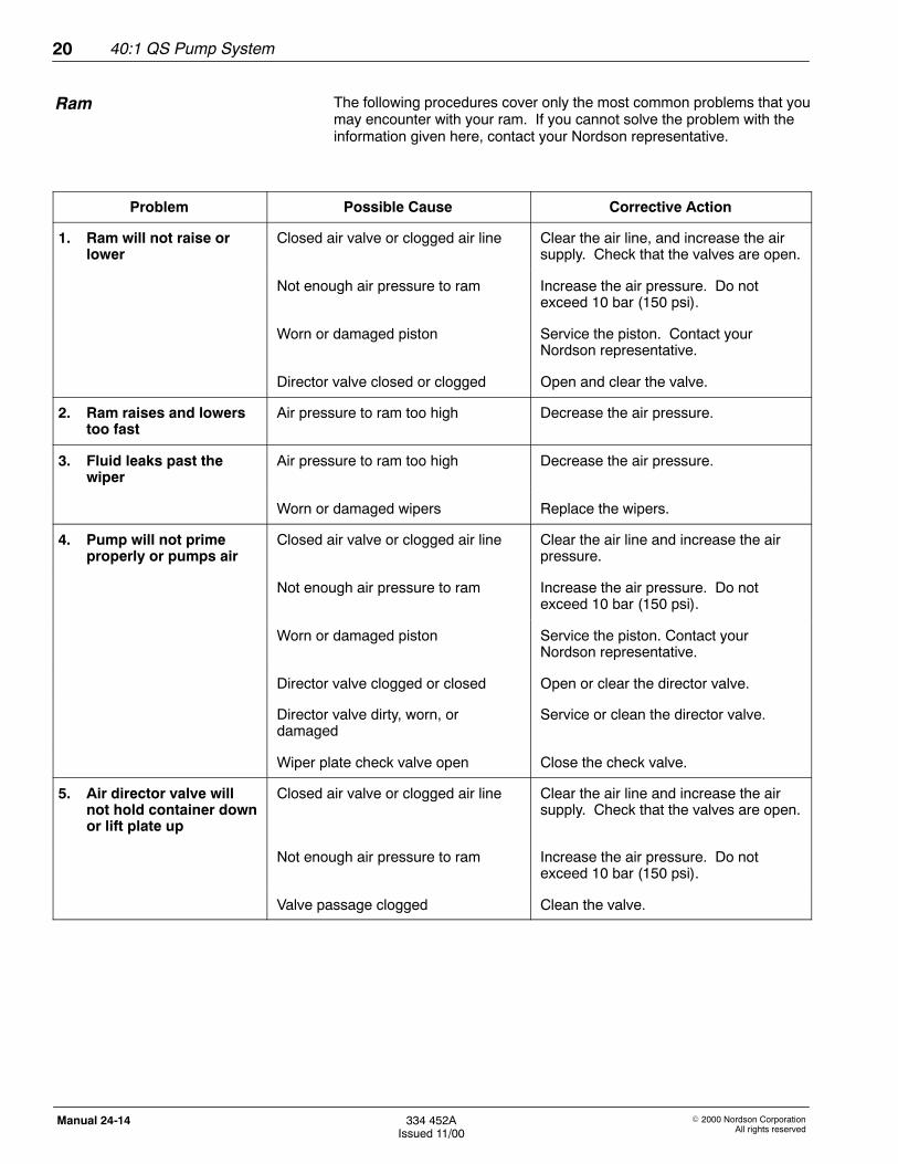
The following procedures cover only the most common problems that youmay encounter with your ram. If you cannot solve the problem with theinformation given here, contact your Nordson representative.
Problem Possible Cause Corrective Action
1. Ram will not raise orlower
Closed air valve or clogged air line Clear the air line, and increase the airsupply. Check that the valves are open.
Not enough air pressure to ram Increase the air pressure. Do notexceed 10 bar (150 psi).
Worn or damaged piston Service the piston. Contact yourNordson representative.
Director valve closed or clogged Open and clear the valve.
2. Ram raises and lowerstoo fast
Air pressure to ram too high Decrease the air pressure.
3. Fluid leaks past thewiper
Air pressure to ram too high Decrease the air pressure.
Worn or damaged wipers Replace the wipers.
4. Pump will not primeproperly or pumps air
Closed air valve or clogged air line Clear the air line and increase the airpressure.
Not enough air pressure to ram Increase the air pressure. Do notexceed 10 bar (150 psi).
Worn or damaged piston Service the piston. Contact yourNordson representative.
Director valve clogged or closed Open or clear the director valve.
Director valve dirty, worn, ordamaged
Service or clean the director valve.
Wiper plate check valve open Close the check valve.
5. Air director valve willnot hold container downor lift plate up
Closed air valve or clogged air line Clear the air line and increase the airsupply. Check that the valves are open.
Not enough air pressure to ram Increase the air pressure. Do notexceed 10 bar (150 psi).
Valve passage clogged Clean the valve.
Ram
40:1 QS Pump System 21
E 2000 Nordson CorporationAll rights reserved
334 452AIssued 11/00
Manual 24-14
This section describes repair procedures for the 40:1 QS pump system.
WARNING: Allow only qualified personnel to perform thefollowing tasks. Follow the safety instructions in this documentand all other related documentation.
WARNING: System or material pressurized. Relieve pressure.Failure to observe may result in serious injury.
WARNING: Wear protective clothing, goggles, and gloveswhen working with this equipment.
WARNING: To reduce the risk of serious bodily injury, includinginjection, splashing in the eyes, or injury from moving parts,always follow the pressure relief procedure when checking orservicing the 40:1 QS pump.
See Figure 1.
Perform these steps to relieve pressure from the 40:1 QS pump system:
1. Shut off the main air and close the air motor on/off valve (5).
2. Disengage the dispensing gun safety latch, if applicable.
3. Hold a metal part of the dispensing gun firmly to the side of agrounded metal pail and trigger the dispensing gun to relievepressure.
4. Open the pump bleed valve (8).
5. If you suspect that the dispensing nozzle or the hose is completelyclogged, or that pressure has not been fully relieved, slowly loosenthe dispensing nozzle retaining nut or the dispensing gun hosecoupling and relieve pressure gradually.
7. Repair
Pressure Relief
40:1 QS Pump System22
E 2000 Nordson CorporationAll rights reserved
334 452AIssued 11/00
Manual 24-14
NOTE: For best results, use all the new parts in the repair kit. Refer tothe Parts section for repair kit components.
Removing the Air Motor from the Ram
See Figure 2.
Perform these steps to remove the air motor from the ram:
1. Remove the air supply hose and the mounting bracket screws.Remove the air motor from the ram.
2. Place the air motor on a workbench and remove the ring (1), washer(2), and nipple (29).
3. Remove the air motor shield (3), the cover (4), and the filter (5).
Disassembling the Housing
See Figure 2.
Perform these steps to disassemble the housing:
1. Unscrew the retainer (13) and remove the spring (12), spring guide(11) and plunger (10) from each side of the housing (8).
2. Remove the bolts (6) and spring washers (7) from the housing.Carefully lift the housing so the axles (9) do not fall out. Remove theaxles, pad washer (15), and pad (14).
NOTE: Do not let the spring-loaded valve (22) jump out of thehousing (18).
3. Lift the housing and rotate it 90 degrees, so it rests on the manifolds(26, 28). Remove your fingers slowly, allowing the spring (19) torelease gently. Remove and inspect the spring-loaded valve, theO-ring (21), the washers (20), and the springs.
WARNING: The openings in the valve plates are very sharp.Handle with care. Failure to observe may result in personalinjury.
4. Remove the manifolds (26, 28) along with the tube (52).
CAUTION: Do not damage the trip rod surface. A damagedtrip rod can not be repaired and must be replaced.
Air Motor Disassembly
40:1 QS Pump System 23
E 2000 Nordson CorporationAll rights reserved
334 452AIssued 11/00
Manual 24-14
Disassembling the Air Motor Base
See Figure 2.
Perform these steps to disassemble the air motor base:
1. Pull the trip rod (47) up. Hold the flats of the trip rod with a wrench,screw off the trip rod nuts (16, 17), and remove the housing (8).
2. Remove the pad (14) and pad washer (15) from the body (33).Remove the bolts (30) and spring washers (31) from the manifolds(26, 28), and remove the manifolds.
3. Remove the screws (23). Remove and check the valveplates (24, 27) and the gaskets (25) for wear or damage. Clean thevalve plates and mating surfaces.
NOTE: When replacing the valve plates, also replace the gaskets.
4. Remove the nuts (34), spring washers (35), washers (36), and body(33).
5. Pull the piston (46), and the trip rod (47) out of the cylinder (42) andthe base (55). Remove the O-ring (45) from the piston.
6. Turn the base over and remove the screw (41). Remove theretainer (40), O-ring (39), and the U-ring packing (38).
Final Disassembly
See Figure 2.
Perform these steps to complete the air motor disassembly:
1. Lock the flats of the piston rod (48) in a vise. Remove the bolts (43)and the hub (44).
NOTE: A damaged trip rod cannot be repaired. Use a new trip rod.
2. Remove the trip rod (47) from the piston (46).
3. Remove the U-packing (49) and the washer (50). Remove thetubes (52), bolts (53), and O-rings (51). Remove the cylinder (42)and the O-rings (37).
4. Turn the base over and remove the ring (61). Remove the V-packingstack (60). Inspect the bearing in place. Replace base if damaged.
5. Remove tie rods (58, 59).
40:1 QS Pump System24
E 2000 Nordson CorporationAll rights reserved
334 452AIssued 11/00
Manual 24-14
Clean all parts thoroughly and inspect for wear or damage. Replaceworn parts. Perform these steps to assemble the air motor:
Assembling the Air Motor Base
See Figure 2.
Perform these steps to assemble the air motor base:
1. Install the tie rods (58, 59). With the base (55) turned over, insert theV-packing stack (60) and install the ring (61).
2. Turn the base over, grease and install the O-ring (37). Carefullylower the cylinder (42) onto the body (33).
3. Install the washer (50) and the U-packing (49). Install the bolts (53),tubes (52), and O-rings (51).
4. Install the trip rod (47) to the piston (46).
NOTE: Apply Loctite 242 or the equivalent to the piston and connectingrod threads before screwing the hub (44) into the piston (46).
5. Install the hub (44) and tighten to 203 Nm (150 ft-lb). Insert the bolts(43) into the hub and tighten to 27--34 Nm (20--25 ft-lb).
6. Turn the base over and install the U-ring packing (38), O-ring (39),and retainer (40). Secure the retainer with the screws (41).
7. Lubricate and install the O-ring (45). Insert the piston rod (48) andthe trip rod (47) into the cylinder (42).
CAUTION: Do not damage the polished surfaces of the trip rodand the piston rod during assembly.
8. Grease and install the O-ring (37). Install the body (33),washers (36), spring washers (35) and nuts (34).
9. Pull the trip rod up, and install the housing (8). Hold the flats of thetrip rod with a wrench and install the nuts (16, 17).
Air Motor Assembly
40:1 QS Pump System 25
E 2000 Nordson CorporationAll rights reserved
334 452AIssued 11/00
Manual 24-14
Assembling the Housing
See Figure 2.
Perform these steps to assemble the housing:
1. Install the gaskets (25) and plates (24, 27) to the manifolds (26, 28),secure the plates with the screws (23).
2. Install the pad (14) and the pad washer (15). Grease and install theO-ring (32) to the manifold (26).
3. Grease and install the O-rings (51) to the tube (52). Install bothmanifolds (26, 28) to the body (33).
4. Install the spring washers (31) and secure the manifold with thebolts (30).
5. Place the spring (19), washer (20), O-ring (21), and spring-loadedvalve (22) into the housing (18). Hold the spring-loaded valve withyour fingers to prevent it from popping out.
6. Rotate the housing and place it between the manifolds (26, 28).Insert the bolts (6) and spring washers (7). Tighten the bolts.
7. Insert the axle (9), plunger (10), spring guide (11), and spring (12).Screw in the retainer (13).
8. Install the filter (5) and the cover (4), the shield (3), the washer (2),the ring (1), and the nipple (29).
Mounting the Air Motor
See Figure 2.
Perform these steps to mount the air motor:
1. Place the air motor on the ram mounting bracket and secure it withthe screws.
2. Attach a supply hose to the nipple and run the air motor slowly tocheck for smooth operation.
40:1 QS Pump System26
E 2000 Nordson CorporationAll rights reserved
334 452AIssued 11/00
Manual 24-14
Flush the system with a compatible solvent and disconnect all hosesbefore disassembling the pump. Remove the air motor before removingthe pump section. Refer to the Air Motor section for more information.
Removing the Pump from the Air Motor
See Figure 3.
Perform these steps to remove the pump from the air motor:
1. Unscrew the nut (2) and remove the collar (3).
2. Unscrew and remove the connecting rods (4, 5). Remove the solventcup (6) and the O-ring (7).
NOTE: If you are using a repair kit to service the pump, use all the newparts. Refer to the Parts section for kit information.
3. Pull the pump away from the air motor, and place the pump housing(21) in a vise with padded jaws.
4. Remove the bleed valve assembly (19).
5. Remove the solvent cup packing nut (8), and the packing nut (13).Remove the V-packings (10, 11), male gland (12) and femalegland (9) from the packing nut (13).
6. Remove the packing nut, O-ring (14), cylinder nut (15), and tieplate (16).
7. Push the displacement rod (22) down so that the priming piston (41)clears the intake cylinder (38).
8. Use two wrenches to oppositely turn and loosen the two hexnuts (39, 42) on the piston rod (28).
9. Remove the valve check plate (40) and the priming piston (41).
Final Disassembly
See Figure 3.
Perform these steps to completely disassemble the pump:
1. Remove the intake cylinder (38) and the O-ring (37).
2. Pull on the piston rod (28) to remove the displacement rod (22) fromthe pump housing (21).
3. Remove the cotter pin (26) and thread the piston rod from the pistonvalve (27).
4. Remove the packing nut (31) from the piston rod. Remove theV-packings and female gland (32, 33, 34, 35).
Pump Disassembly
40:1 QS Pump System 27
E 2000 Nordson CorporationAll rights reserved
334 452AIssued 11/00
Manual 24-14
CAUTION: Be careful not to drop or lose the piston ball (23).
5. Unscrew the piston valve from the displacement rod.
6. Remove the male gland (12), V-packing (10, 11), washer (24) andfemale gland (25). Remove the rod guide (30).
7. Remove the pump cylinder (29) and O-rings (14).
8. Inspect the outer surface of the displacement rod and the innersurface of the pump cylinder for scoring and wear by holding them upto a light or running a finger over the surface. Replace these parts ifnecessary.
NOTE: If the displacement rod is worn, the V-packing will not sealproperly and the pump will leak. If the pump cylinder is worn, the pumpwill not stall against pressure.
9. Clean all parts in a compatible solvent. Inspect all parts and replacethem if necessary.
Lubricate all pump components with a compatible lubricant. Performthese steps to assemble the pump:
Assembling the Pump Housing
See Figure 3.
Perform these steps to assemble the pump housing:
1. Place the tie plate (16) on the pump housing (21); tighten the cylindernut (15); and install the bleeder valve assembly (19).
2. Place the O-ring (14) on the packing nut (13). Screw the packing nutinto the pump housing.
3. Place the first pre-assembled V-packing stack (9, 10, 11,12) into thepacking nut (13). Be sure that the lips of the V-packing stack arefacing down.
4. Place the O-ring (7) in the groove of the solvent cup packing nut (8).Loosely install the solvent cup packing nut and the solvent cup (6)into the pump housing.
5. Install the second pre-assembled V-packing stack (10, 11), malegland (12), and female gland (25) on the piston valve (27) with thelips of the V-packings facing up.
6. Install the washer (24) on top of the second V-packing stack.
7. Install the piston ball (23) in the bottom of the displacement rod (22).
Pump Assembly
40:1 QS Pump System28
E 2000 Nordson CorporationAll rights reserved
334 452AIssued 11/00
Manual 24-14
8. Apply medium grade thread sealant to the threads of the piston valveand piston valve housing, and screw the piston valve into the pistonvalve housing. Tighten to 81--102 Nm (60--76 ft-lb).
9. Screw the piston rod (28) into the piston valve and align the holes toinsert the cotter pin (26).
Final Pump Assembly
See Figure 3.
Perform these steps to completely assemble the pump:
1. Place the pump housing (21) in a vise. Install the new O-rings (14)on the pump cylinder (29). Lubricate the cylinder and slide it into thepump housing as far as possible.
2. Slide the rod guide (30) onto the piston rod (28), with the flat sidefacing down.
3. Install the displacement rod assembly through the bottom of thepump, guiding it carefully through the throat packings.
4. Install the third pre-assembled, V-packing stack (32, 33, 34, 35) intothe housing of the valve (36). Be sure that the lips of the V-packingsare facing up. Install the packing nut (31) and tighten to 34--47 Nm(25--35 ft-lb). Slide the assembly (packing nut first) onto the pistonrod.
5. Place the O-ring (37) around the intake valve cylinder (38). Screwthe cylinder into the pump housing. Tighten to 129--149 Nm(94--110 ft-lb).
6. Thread the nut (39) onto the bottom of the piston rod. Install thecheck valve plate (40), priming piston (41), and nut (42). Hold theupper nut (39) while tightening the bottom nut to 54--81 Nm(40--60 ft-lb).
7. Tighten the packing nut (31). Tighten the solvent cup packing nut (8)to 54--81 Nm (40--60 ft-lb).
8. Thread the connecting rods (4, 5) into the displacement rod (22);install the collar (3); and tighten the nut (2) to reconnect the pump tothe air motor (1).
NOTE: Contact your Nordson representative to verify that you arechoosing the correct type of solvent cup fluid for your application.
9. Fill the solvent cup (6) with Nordson K-solvent or a solvent compatiblewith the material being pumped.
10. Bleed the pump.
40:1 QS Pump System 29
E 2000 Nordson CorporationAll rights reserved
334 452AIssued 11/00
Manual 24-14
See Figure 4.
Before disassembling the ram piston rod (18), tighten the nut (5) to stopair from leaking from the piston. If air continues to leak from the piston,perform these steps to disassemble and service the ram piston rodpacking:
1. Relieve pressure.
2. Remove the nuts (1) and lock washers (2).
3. Remove the beam (3).
4. Remove the nut (5) from the tie rod (14); remove the housing (12);and slide it up and off the tie rod.
5. Remove the bearing (6), female gland (7), V-packings (9, 10), malegland (8), housing (12), and seal (13).
6. Inspect the parts for wear or damage. Replace if necessary.
See Figure 4.
Perform these steps to assemble the piston rod packing:
1. Install the seal (13) and housing (12). Slide the male gland (8) ontothe tie rod (14).
2. Lubricate the V-packings (9, 10) and slide them onto the tie rod one ata time, with the lips facing down.
3. Slide the female gland (7) onto the tie rod and push all of thepackings into the housing (12). Slide the bearing (6) onto the tie rod.
CAUTION: Do not over tighten. You could damage theV-packings.
4. Slide the nut (5) onto the tie rod; screw it onto the housing; andhand-tighten.
5. Reinstall the beam (3) on the tie rods and piston rods (18) using thenuts (1) and the lockwashers (2).
Ram Piston Rod PackingDisassembly
Ram Piston Rod PackingAssembly
40:1 QS Pump System30
E 2000 Nordson CorporationAll rights reserved
334 452AIssued 11/00
Manual 24-14
See Figure 4.
Perform these steps to disassemble the piston:
1. Relieve the system air pressure.
2. Remove the nut (1) and lock washer (2). Remove the beam (3).Refer to Piston Rod Packing Replacement.
3. Remove the cap (4) from the tie rod (14). Loosen the nut (5) andslide the nut, the bearing (6), and housing (12) up off the tie rod.
CAUTION: If the tie rod is cocked to one side, the piston orinside surface of the air cylinder could be damaged.
4. Carefully pull the tie rod and piston (22) straight up out of the rambase and air cylinder (40).
5. Carefully lay the piston and the tie rod down on a workbench.Remove the nut (25), washer (24), piston cap (23), U-packing (21),piston bushing (16), piston, washer (19) and spring (15).
6. Inspect the parts for wear or damage. Replace if necessary.
See Figure 4.
Perform these steps to assemble and install the ram piston into the ram:
1. Install the O-ring (20) to the piston (22) and lubricate both withgrease.
2. Install the spring (15), washer (19), piston, piston bushing (16),U-packing (21), piston cap (23), washer (24), and nut (25). Tightenthe nut.
CAUTION: Do not over tighten. You may damage the packing.
3. Carefully insert the piston and the tie rod (14) into the ram base andair cylinder (40). Push the tie rod straight down into the cylinder.Slide the housing (12), bearing (6), and nut (5) down onto the tie rodand hand-tighten.
4. Install the cap (4) and the beam (3). Install the lockwashers (2) andthe nuts (1).
Ram Piston Disassembly
Ram Piston Assembly andInstallation
40:1 QS Pump System 31
E 2000 Nordson CorporationAll rights reserved
334 452AIssued 11/00
Manual 24-14
To order parts, call the Nordson Customer Service Center or your localNordson representative. Use the parts list, and the accompanyingillustration, to describe and locate parts correctly.
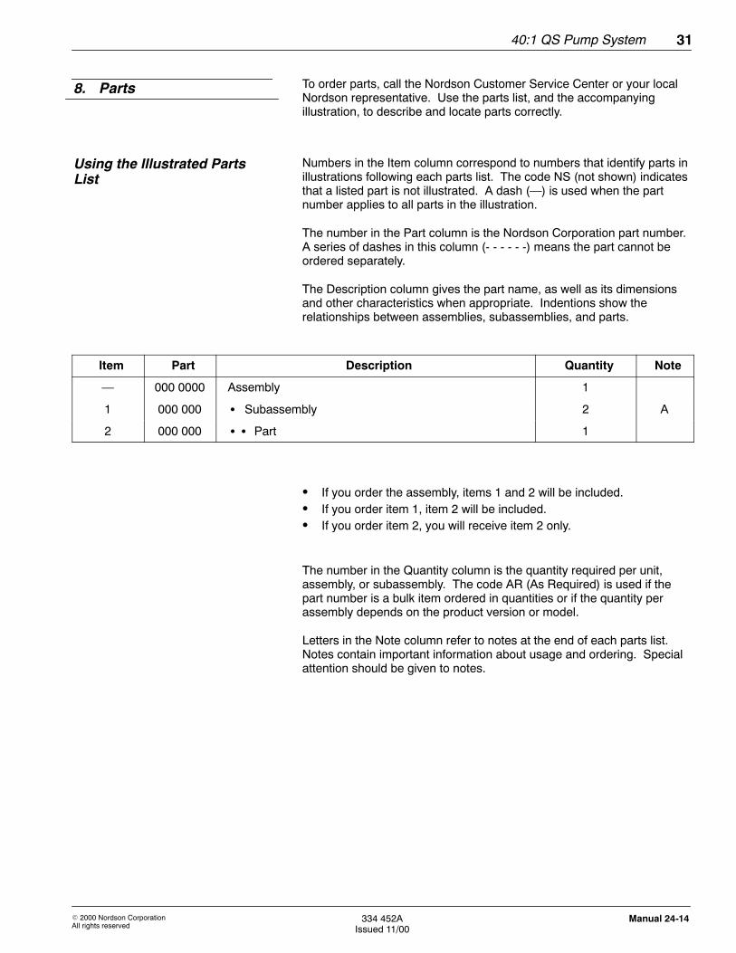
Numbers in the Item column correspond to numbers that identify parts inillustrations following each parts list. The code NS (not shown) indicatesthat a listed part is not illustrated. A dash (—) is used when the partnumber applies to all parts in the illustration.
The number in the Part column is the Nordson Corporation part number.A series of dashes in this column (- - - - - -) means the part cannot beordered separately.
The Description column gives the part name, as well as its dimensionsand other characteristics when appropriate. Indentions show therelationships between assemblies, subassemblies, and parts.
Item Part Description Quantity Note
— 000 0000 Assembly 1
1 000 000 S Subassembly 2 A
2 000 000 S S Part 1
S If you order the assembly, items 1 and 2 will be included.S If you order item 1, item 2 will be included.S If you order item 2, you will receive item 2 only.
The number in the Quantity column is the quantity required per unit,assembly, or subassembly. The code AR (As Required) is used if thepart number is a bulk item ordered in quantities or if the quantity perassembly depends on the product version or model.
Letters in the Note column refer to notes at the end of each parts list.Notes contain important information about usage and ordering. Specialattention should be given to notes.
8. Parts
Using the Illustrated PartsList
40:1 QS Pump System32
E 2000 Nordson CorporationAll rights reserved
334 452AIssued 11/00
Manual 24-14
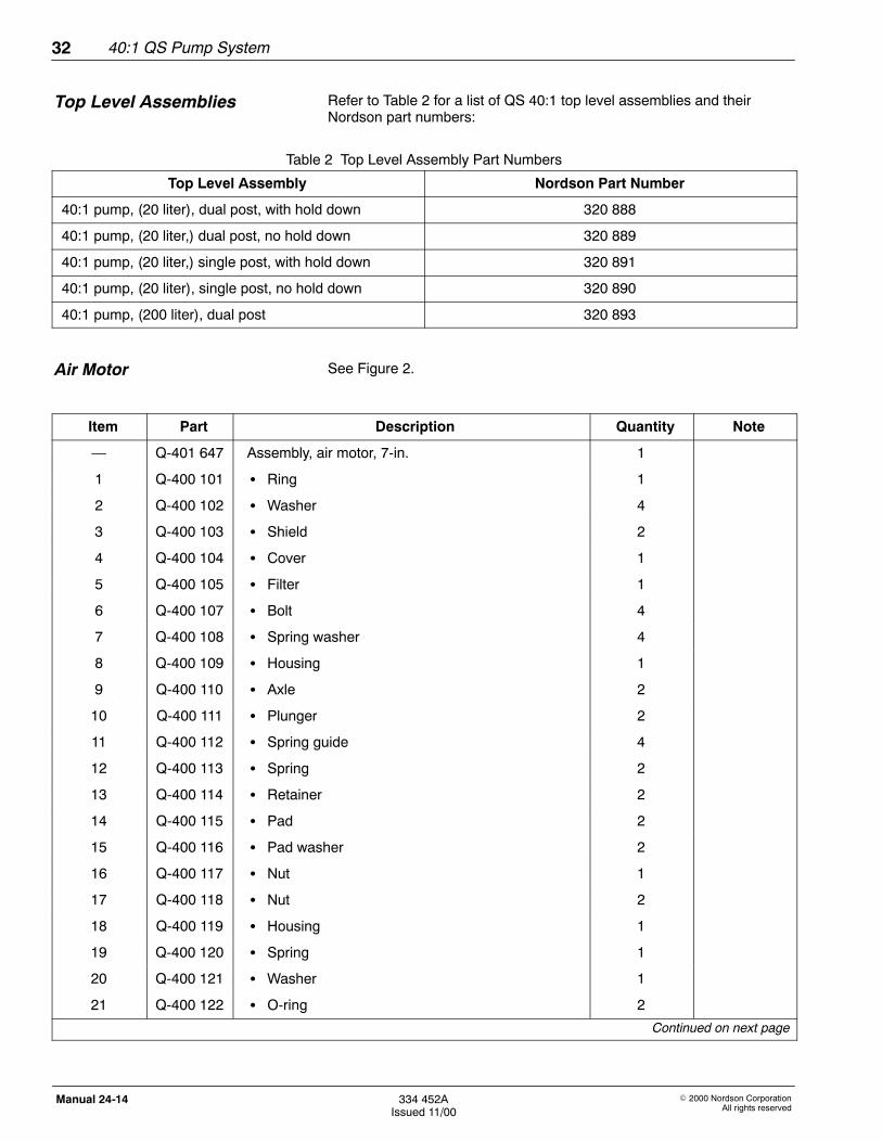
Refer to Table 2 for a list of QS 40:1 top level assemblies and theirNordson part numbers:
Table 2 Top Level Assembly Part Numbers
Top Level Assembly Nordson Part Number
40:1 pump, (20 liter), dual post, with hold down 320 888
40:1 pump, (20 liter,) dual post, no hold down 320 889
40:1 pump, (20 liter,) single post, with hold down 320 891
40:1 pump, (20 liter), single post, no hold down 320 890
40:1 pump, (200 liter), dual post 320 893
See Figure 2.
Item Part Description Quantity Note
— Q-401 647 Assembly, air motor, 7-in. 1
1 Q-400 101 S Ring 1
2 Q-400 102 S Washer 4
3 Q-400 103 S Shield 2
4 Q-400 104 S Cover 1
5 Q-400 105 S Filter 1
6 Q-400 107 S Bolt 4
7 Q-400 108 S Spring washer 4
8 Q-400 109 S Housing 1
9 Q-400 110 S Axle 2
10 Q-400 111 S Plunger 2
11 Q-400 112 S Spring guide 4
12 Q-400 113 S Spring 2
13 Q-400 114 S Retainer 2
14 Q-400 115 S Pad 2
15 Q-400 116 S Pad washer 2
16 Q-400 117 S Nut 1
17 Q-400 118 S Nut 2
18 Q-400 119 S Housing 1
19 Q-400 120 S Spring 1
20 Q-400 121 S Washer 1
21 Q-400 122 S O-ring 2
Continued on next page
Top Level Assemblies
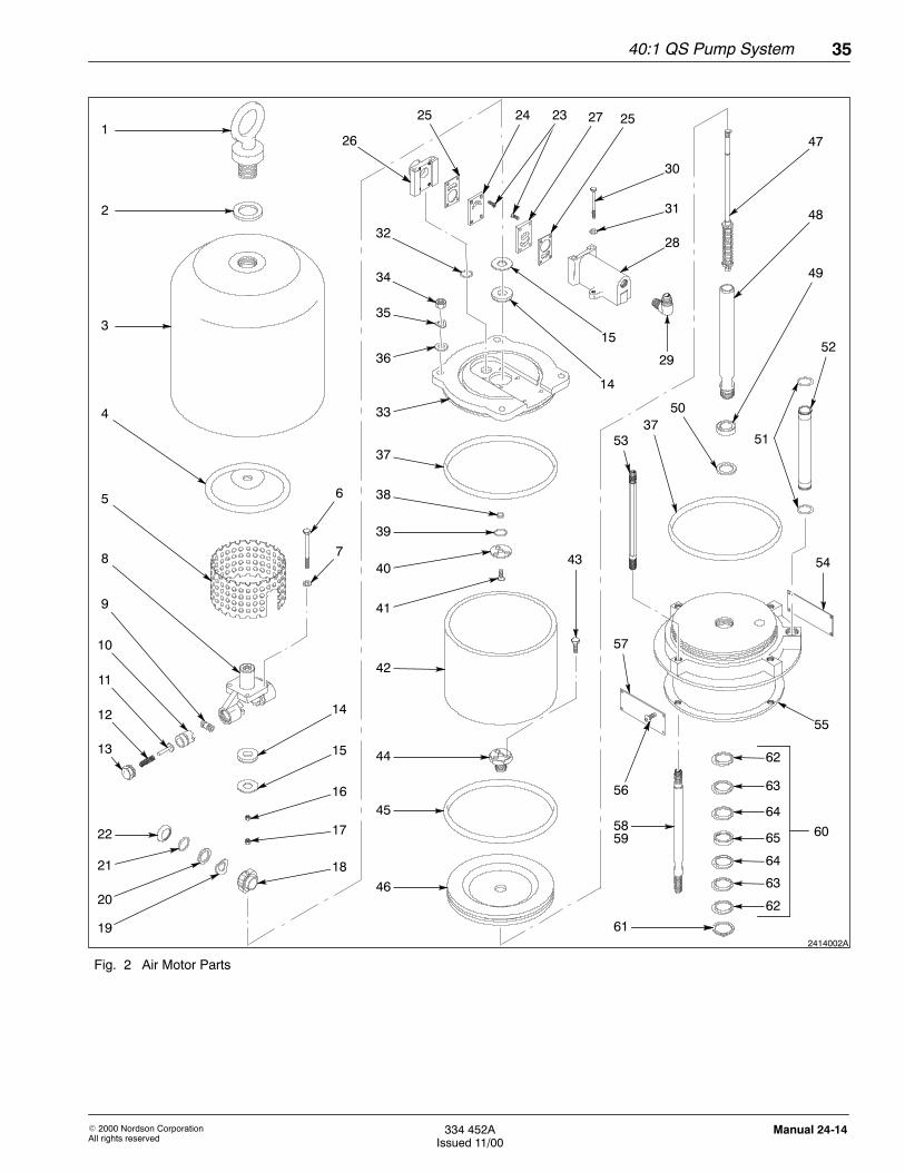
Air Motor
40:1 QS Pump System 33
E 2000 Nordson CorporationAll rights reserved
334 452AIssued 11/00
Manual 24-14
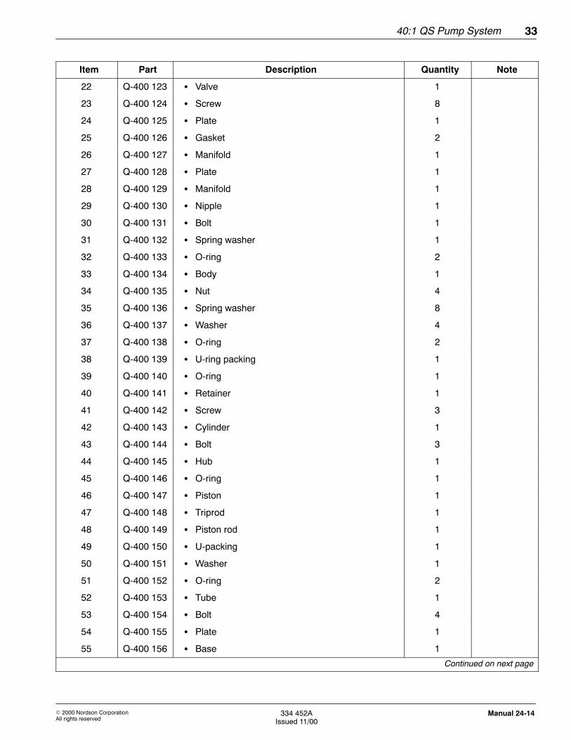
Item Part Description Quantity Note
22 Q-400 123 S Valve 1
23 Q-400 124 S Screw 8
24 Q-400 125 S Plate 1
25 Q-400 126 S Gasket 2
26 Q-400 127 S Manifold 1
27 Q-400 128 S Plate 1
28 Q-400 129 S Manifold 1
29 Q-400 130 S Nipple 1
30 Q-400 131 S Bolt 1
31 Q-400 132 S Spring washer 1
32 Q-400 133 S O-ring 2
33 Q-400 134 S Body 1
34 Q-400 135 S Nut 4
35 Q-400 136 S Spring washer 8
36 Q-400 137 S Washer 4
37 Q-400 138 S O-ring 2
38 Q-400 139 S U-ring packing 1
39 Q-400 140 S O-ring 1
40 Q-400 141 S Retainer 1
41 Q-400 142 S Screw 3
42 Q-400 143 S Cylinder 1
43 Q-400 144 S Bolt 3
44 Q-400 145 S Hub 1
45 Q-400 146 S O-ring 1
46 Q-400 147 S Piston 1
47 Q-400 148 S Triprod 1
48 Q-400 149 S Piston rod 1
49 Q-400 150 S U-packing 1
50 Q-400 151 S Washer 1
51 Q-400 152 S O-ring 2
52 Q-400 153 S Tube 1
53 Q-400 154 S Bolt 4
54 Q-400 155 S Plate 1
55 Q-400 156 S Base 1
Continued on next page
40:1 QS Pump System34
E 2000 Nordson CorporationAll rights reserved
334 452AIssued 11/00
Manual 24-14
Item Part Description Quantity Note
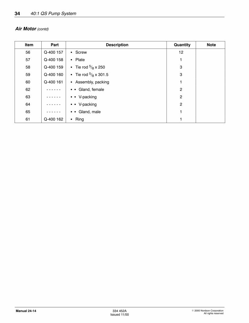
56 Q-400 157 S Screw 12
57 Q-400 158 S Plate 1
58 Q-400 159 S Tie rod 5/8 x 250 3
59 Q-400 160 S Tie rod 5/8 x 301.5 3
60 Q-400 161 S Assembly, packing 1
62 - - - - - - S S Gland, female 2
63 - - - - - - S S V-packing 2
64 - - - - - - S S V-packing 2
65 - - - - - - S S Gland, male 1
61 Q-400 162 S Ring 1
Air Motor (contd)
40:1 QS Pump System 35
E 2000 Nordson CorporationAll rights reserved
334 452AIssued 11/00
Manual 24-14
2414002A
1
3
4
5
32
8
19
14
15
16
17
18
20
21
22
13
12
11
10
9
6
7
26
25
14
15
29
28
31
30
27 25
34
36
35
33
37
38
42
41
40
39
44
45
46
43
47
48
49
56
58
57
5337
50
52
51
60
54
24 23
2
59
61
62
55
63
64
65
64
63
62
Fig. 2 Air Motor Parts
40:1 QS Pump System36
E 2000 Nordson CorporationAll rights reserved
334 452AIssued 11/00
Manual 24-14
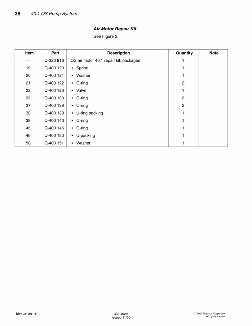
Air Motor Repair Kit
See Figure 2.
Item Part Description Quantity Note
— Q-320 916 QS air motor 40:1 repair kit, packaged 1
19 Q-400 120 S Spring 1
20 Q-400 121 S Washer 1
21 Q-400 122 S O-ring 2
22 Q-400 123 S Valve 1
32 Q-400 133 S O-ring 2
37 Q-400 138 S O-ring 2
38 Q-400 139 S U-ring packing 1
39 Q-400 140 S O-ring 1
45 Q-400 146 S O-ring 1
49 Q-400 150 S U-packing 1
50 Q-400 151 S Washer 1
40:1 QS Pump System 37
E 2000 Nordson CorporationAll rights reserved
334 452AIssued 11/00
Manual 24-14
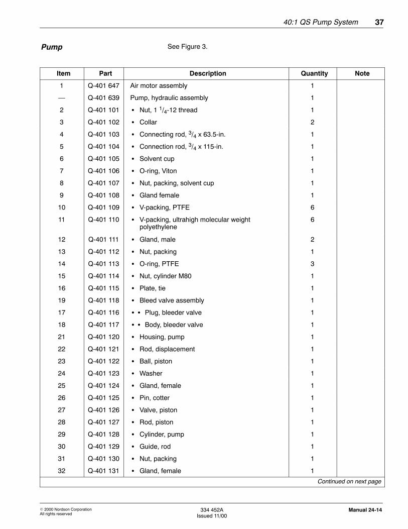
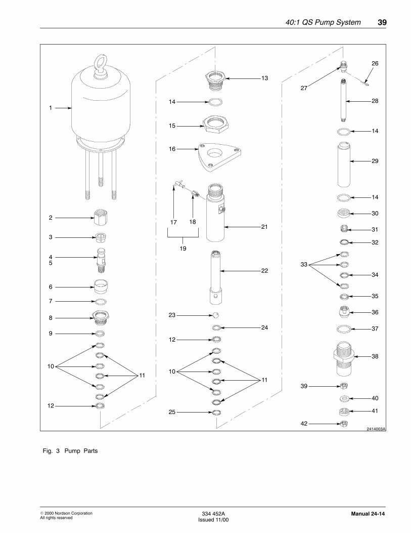
See Figure 3.
Item Part Description Quantity Note
1 Q-401 647 Air motor assembly 1
— Q-401 639 Pump, hydraulic assembly 1
2 Q-401 101 S Nut, 1 1/4-12 thread 1
3 Q-401 102 S Collar 2
4 Q-401 103 S Connecting rod, 3/4 x 63.5-in. 1
5 Q-401 104 S Connection rod, 3/4 x 115-in. 1
6 Q-401 105 S Solvent cup 1
7 Q-401 106 S O-ring, Viton 1
8 Q-401 107 S Nut, packing, solvent cup 1
9 Q-401 108 S Gland female 1
10 Q-401 109 S V-packing, PTFE 6
11 Q-401 110 S V-packing, ultrahigh molecular weightpolyethylene
6
12 Q-401 111 S Gland, male 2
13 Q-401 112 S Nut, packing 1
14 Q-401 113 S O-ring, PTFE 3
15 Q-401 114 S Nut, cylinder M80 1
16 Q-401 115 S Plate, tie 1
19 Q-401 118 S Bleed valve assembly 1
17 Q-401 116 S S Plug, bleeder valve 1
18 Q-401 117 S S Body, bleeder valve 1
21 Q-401 120 S Housing, pump 1
22 Q-401 121 S Rod, displacement 1
23 Q-401 122 S Ball, piston 1
24 Q-401 123 S Washer 1
25 Q-401 124 S Gland, female 1
26 Q-401 125 S Pin, cotter 1
27 Q-401 126 S Valve, piston 1
28 Q-401 127 S Rod, piston 1
29 Q-401 128 S Cylinder, pump 1
30 Q-401 129 S Guide, rod 1
31 Q-401 130 S Nut, packing 1
32 Q-401 131 S Gland, female 1
Continued on next page
Pump
40:1 QS Pump System38
E 2000 Nordson CorporationAll rights reserved
334 452AIssued 11/00
Manual 24-14
Item Part Description Quantity Note
33 Q-401 132 S V-packing, ultrahigh molecular weightpolyethylene
3
34 Q-401 133 S V-packing, PTFE 1
35 Q-401 131 S Gland, female 1
36 Q-401 135 S Valve 1
37 Q-401 136 S O-ring, PTFE 1
38 Q-401 137 S Cylinder, valve, intake 1
39 Q-401 138 S Nut, machine, hex, M16 1
40 Q-401 139 S Plate, valve, check 1
41 Q-401 140 S Piston, priming 1
42 Q-401 141 S Nut, hex, M16 1
Pump (contd)
40:1 QS Pump System 39
E 2000 Nordson CorporationAll rights reserved
334 452AIssued 11/00
Manual 24-14
2414003A
1
2
3
4
6
7
8
9
12
10
11
14
13
15
16
17 1821
22
23
12
24
1011
25
26
28
14
29
14
31
34
30
33
35
36
37
38
41
42
39
40
5
19
27
32
Fig. 3 Pump Parts
40:1 QS Pump System40
E 2000 Nordson CorporationAll rights reserved
334 452AIssued 11/00
Manual 24-14
Pump Repair Kit
See Figure 3.
Item Part Description Quantity Note
— Q-320 917 Pump repair kit 1
7 Q-401 106 S O-ring, Viton 1
9 Q-401 108 S Gland female 1
10 Q-401 109 S V-packing, PTFE 6
11 Q-401 110 S V-packing, ultrahigh molecular weightpolyethylene
6
12 Q-401 111 S Gland, male 2
14 Q-401 113 S O-ring, PTFE 3
23 Q-401 122 S Ball, piston 1
24 Q-401 123 S Washer 1
25 Q-401 124 S Gland, female 1
33 Q-401 132 S V-packing, ultrahigh molecular weightpolyethylene
3
34 Q-401 133 S V-packing, PTFE 1
35 Q-401 134 S Gland, female 1
37 Q-401 136 S O-ring, PTFE 1
40:1 QS Pump System 41
E 2000 Nordson CorporationAll rights reserved
334 452AIssued 11/00
Manual 24-14
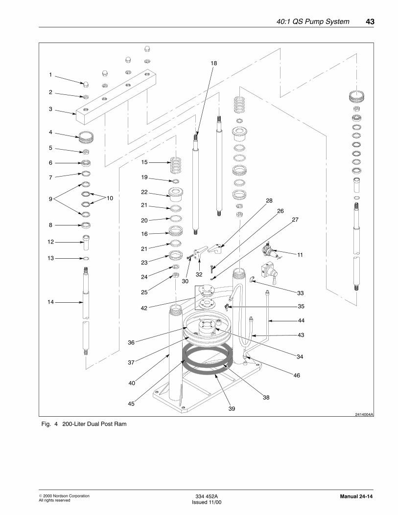
See Figure 4.
Item Part Description Quantity Note
— - - - - - - Assembly, 200-liter dual post ram 1
1 Q-550 201 S Nut 4
2 Q-550 202 S Washer. lock 4
3 Q-550 203 S Beam 1
4 Q-550 204 S Cap 2
5 Q-550 205 S Nut 2
6 Q-550 206 S Bearing 2
7 Q-550 207 S Gland, female 2
8 Q-550 208 S Gland, male 2
9 Q-550 209 S V-packing, PTFE 4
10 Q-550 210 S V-packing 4
11 Q-407 652 S Kit, regulator 1
12 Q-550 211 S Housing 1
13 Q-550 212 S Seal 2
14 Q-550 213 S Rod, tie 2
15 Q-550 214 S Spring 2
16 Q-550 215 S Bushing, piston 2
18 Q-550 217 S Rod 2
19 Q-550 219 S Washer 2
20 Q-550 220 S O-ring 2
21 Q-550 221 S U-packing 4
22 Q-550 222 S Piston 2
23 Q-550 223 S Cap, piston 2
24 Q-550 247 S Washer, lock 2
25 Q-550 228 S Nut 2
26 Q-550 229 S Screw 4
27 Q-550 230 S Washer, lock 4
28 Q-550 233 S Bracket 1
29 Q-550 234 S Nut 2
30 Q-550 231 S Screw 4
31 Q-550 235 S Washer, lock 2
32 Q-550 237 S Bracket 2
Continued on next page
200-Liter Dual Post Ram
40:1 QS Pump System42
E 2000 Nordson CorporationAll rights reserved
334 452AIssued 11/00
Manual 24-14
Item Part Description Quantity Note
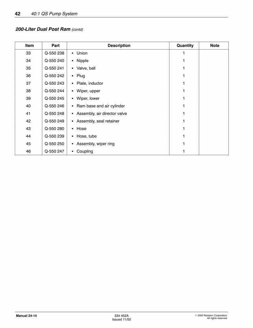
33 Q-550 238 S Union 1
34 Q-550 240 S Nipple 1
35 Q-550 241 S Valve, ball 1
36 Q-550 242 S Plug 1
37 Q-550 243 S Plate, inductor 1
38 Q-550 244 S Wiper, upper 1
39 Q-550 245 S Wiper, lower 1
40 Q-550 246 S Ram base and air cylinder 1
41 Q-550 248 S Assembly, air director valve 1
42 Q-550 249 S Assembly, seal retainer 1
43 Q-550 280 S Hose 1
44 Q-550 239 S Hose, tube 1
45 Q-550 250 S Assembly, wiper ring 1
46 Q-550 247 S Coupling 1
200-Liter Dual Post Ram (contd)
40:1 QS Pump System 43
E 2000 Nordson CorporationAll rights reserved
334 452AIssued 11/00
Manual 24-14
2414004A
1
2
3
8
12
13
14
5
6
7
9
4
15
19
25
24
23
21
16
20
21
22
40
39
10
35
43
46
44
33
11
30
28
26
27
42
32
38
37
36
34
45
18
Fig. 4 200-Liter Dual Post Ram
40:1 QS Pump System44
E 2000 Nordson CorporationAll rights reserved
334 452AIssued 11/00
Manual 24-14
200-Liter Dual Post Repair Kit
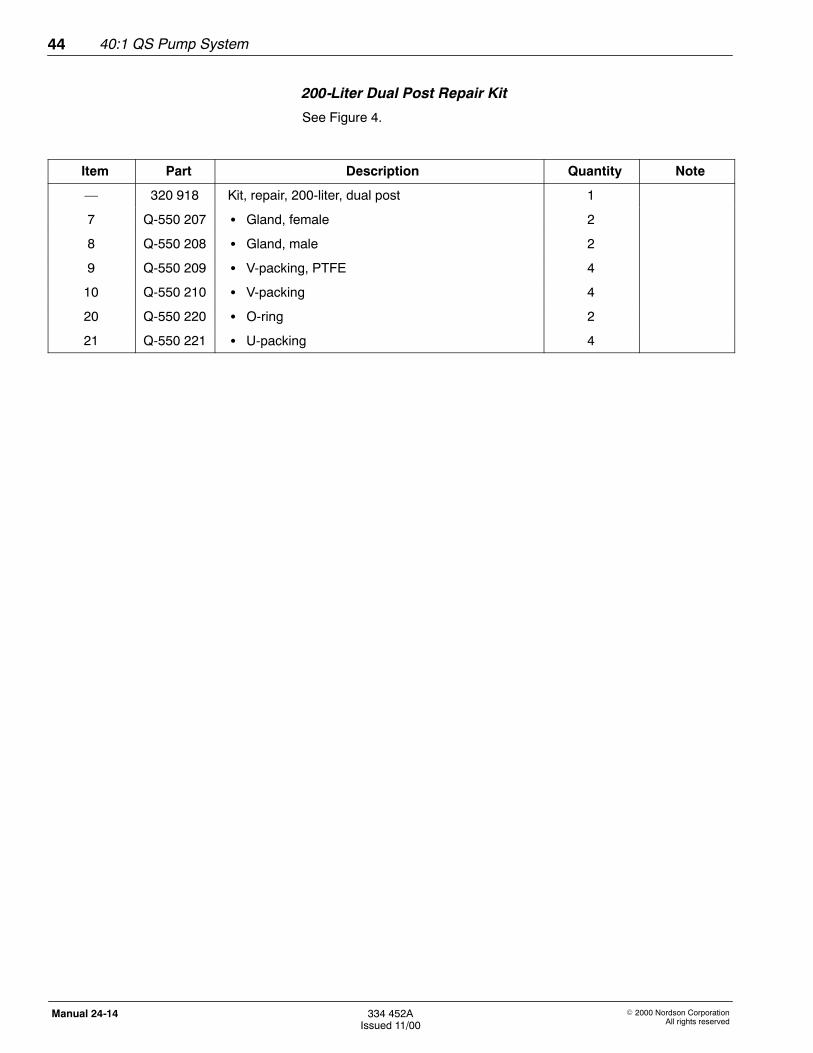
See Figure 4.
Item Part Description Quantity Note
— 320 918 Kit, repair, 200-liter, dual post 1
7 Q-550 207 S Gland, female 2
8 Q-550 208 S Gland, male 2
9 Q-550 209 S V-packing, PTFE 4
10 Q-550 210 S V-packing 4
20 Q-550 220 S O-ring 2
21 Q-550 221 S U-packing 4
40:1 QS Pump System 45
E 2000 Nordson CorporationAll rights reserved
334 452AIssued 11/00
Manual 24-14
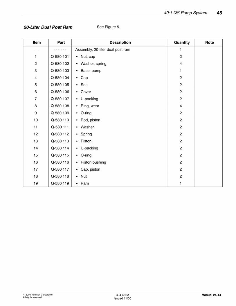
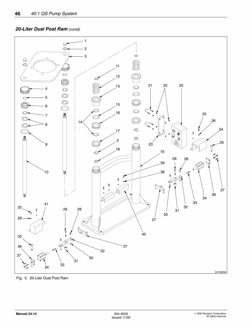
See Figure 5.
Item Part Description Quantity Note
— - - - - - - Assembly, 20-liter dual post ram 1
1 Q-580 101 S Nut, cap 2
2 Q-580 102 S Washer, spring 4
3 Q-580 103 S Base, pump 1
4 Q-580 104 S Cap 2
5 Q-580 105 S Seal 2
6 Q-580 106 S Cover 2
7 Q-580 107 S U-packing 2
8 Q-580 108 S Ring, wear 4
9 Q-580 109 S O-ring 2
10 Q-580 110 S Rod, piston 2
11 Q-580 111 S Washer 2
12 Q-580 112 S Spring 2
13 Q-580 113 S Piston 2
14 Q-580 114 S U-packing 2
15 Q-580 115 S O-ring 2
16 Q-580 116 S Piston bushing 2
17 Q-580 117 S Cap, piston 2
18 Q-580 118 S Nut 2
19 Q-580 119 S Ram 1
20-Liter Dual Post Ram
40:1 QS Pump System46
E 2000 Nordson CorporationAll rights reserved
334 452AIssued 11/00
Manual 24-14
2414005A
3
2
10
9
8
7
6
5
4
18
2
17
16
13
12
11
15
21 22
23
20
25
26
24
27
32
29 28
37
30
41
3634
33
31
40
19
39
38
35
1
30
29 28
35
32
3133
34
36
37
25
26
27
14
Fig. 5 20-Liter Dual Post Ram
20-Liter Dual Post Ram (contd)
40:1 QS Pump System 47
E 2000 Nordson CorporationAll rights reserved
334 452AIssued 11/00
Manual 24-14
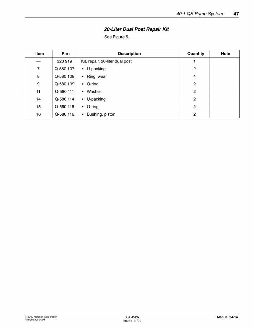
20-Liter Dual Post Repair Kit
See Figure 5.
Item Part Description Quantity Note
— 320 919 Kit, repair, 20-liter dual post 1
7 Q-580 107 S U-packing 2
8 Q-580 108 S Ring, wear 4
9 Q-580 109 S O-ring 2
11 Q-580 111 S Washer 2
14 Q-580 114 S U-packing 2
15 Q-580 115 S O-ring 2
16 Q-580 116 S Bushing, piston 2
40:1 QS Pump System48
E 2000 Nordson CorporationAll rights reserved
334 452AIssued 11/00
Manual 24-14
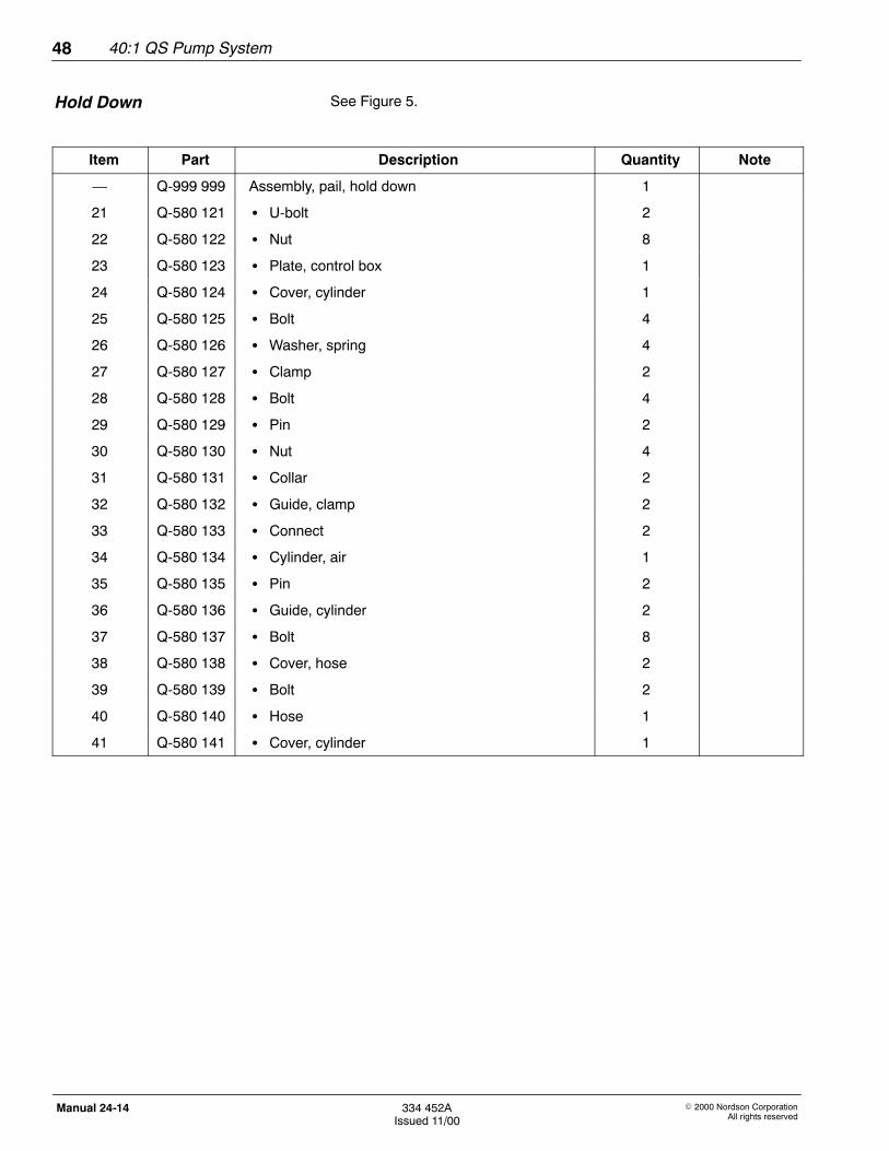
See Figure 5.
Item Part Description Quantity Note
— Q-999 999 Assembly, pail, hold down 1
21 Q-580 121 S U-bolt 2
22 Q-580 122 S Nut 8
23 Q-580 123 S Plate, control box 1
24 Q-580 124 S Cover, cylinder 1
25 Q-580 125 S Bolt 4
26 Q-580 126 S Washer, spring 4
27 Q-580 127 S Clamp 2
28 Q-580 128 S Bolt 4
29 Q-580 129 S Pin 2
30 Q-580 130 S Nut 4
31 Q-580 131 S Collar 2
32 Q-580 132 S Guide, clamp 2
33 Q-580 133 S Connect 2
34 Q-580 134 S Cylinder, air 1
35 Q-580 135 S Pin 2
36 Q-580 136 S Guide, cylinder 2
37 Q-580 137 S Bolt 8
38 Q-580 138 S Cover, hose 2
39 Q-580 139 S Bolt 2
40 Q-580 140 S Hose 1
41 Q-580 141 S Cover, cylinder 1
Hold Down
40:1 QS Pump System 49
E 2000 Nordson CorporationAll rights reserved
334 452AIssued 11/00
Manual 24-14
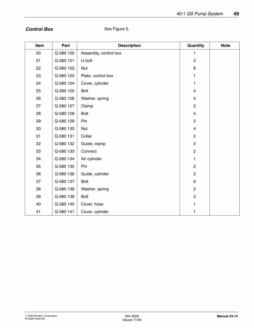
See Figure 5.
Item Part Description Quantity Note
20 Q-580 120 Assembly, control box 1
21 Q-580 121 U-bolt 2
22 Q-580 122 Nut 8
23 Q-580 123 Plate, control box 1
24 Q-580 124 Cover, cylinder 1
25 Q-580 125 Bolt 4
26 Q-580 126 Washer, spring 4
27 Q-580 127 Clamp 2
28 Q-580 128 Bolt 4
29 Q-580 129 Pin 2
30 Q-580 130 Nut 4
31 Q-580 131 Collar 2
32 Q-580 132 Guide, clamp 2
33 Q-580 133 Connect 2
34 Q-580 134 Air cylinder 1
35 Q-580 135 Pin 2
36 Q-580 136 Guide, cylinder 2
37 Q-580 137 Bolt 8
38 Q-580 138 Washer, spring 2
39 Q-580 139 Bolt 2
40 Q-580 140 Cover, hose 1
41 Q-580 141 Cover, cylinder 1
Control Box
40:1 QS Pump System50
E 2000 Nordson CorporationAll rights reserved
334 452AIssued 11/00
Manual 24-14
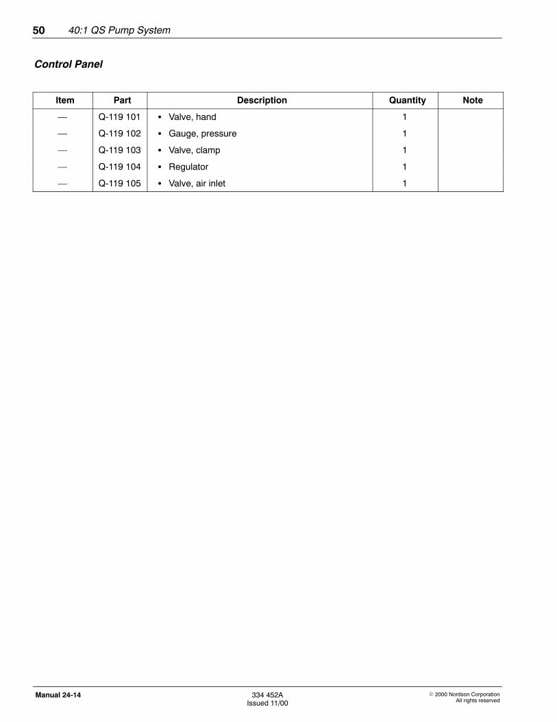
Item Part Description Quantity Note
— Q-119 101 S Valve, hand 1
— Q-119 102 S Gauge, pressure 1
— Q-119 103 S Valve, clamp 1
— Q-119 104 S Regulator 1
— Q-119 105 S Valve, air inlet 1
Control Panel
40:1 QS Pump System 51
E 2000 Nordson CorporationAll rights reserved
334 452AIssued 11/00
Manual 24-14
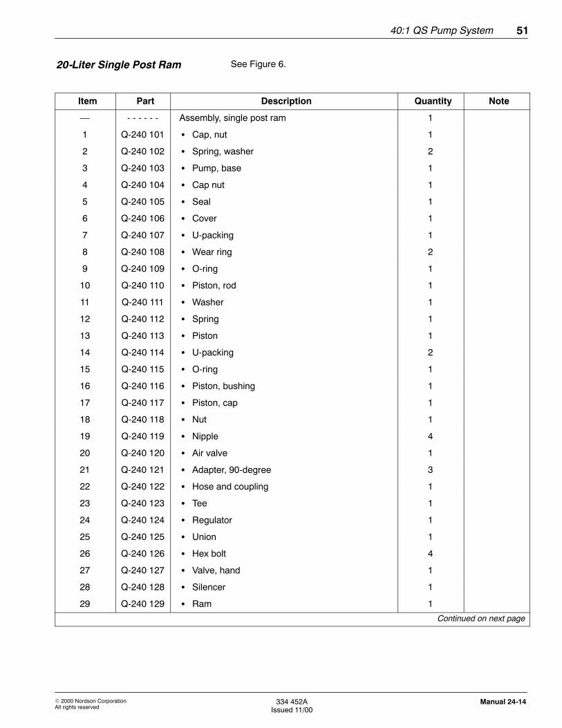
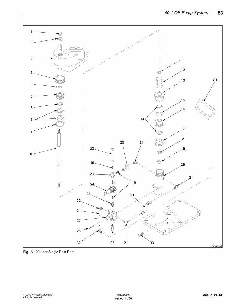
See Figure 6.
Item Part Description Quantity Note
— - - - - - - Assembly, single post ram 1
1 Q-240 101 S Cap, nut 1
2 Q-240 102 S Spring, washer 2
3 Q-240 103 S Pump, base 1
4 Q-240 104 S Cap nut 1
5 Q-240 105 S Seal 1
6 Q-240 106 S Cover 1
7 Q-240 107 S U-packing 1
8 Q-240 108 S Wear ring 2
9 Q-240 109 S O-ring 1
10 Q-240 110 S Piston, rod 1
11 Q-240 111 S Washer 1
12 Q-240 112 S Spring 1
13 Q-240 113 S Piston 1
14 Q-240 114 S U-packing 2
15 Q-240 115 S O-ring 1
16 Q-240 116 S Piston, bushing 1
17 Q-240 117 S Piston, cap 1
18 Q-240 118 S Nut 1
19 Q-240 119 S Nipple 4
20 Q-240 120 S Air valve 1
21 Q-240 121 S Adapter, 90-degree 3
22 Q-240 122 S Hose and coupling 1
23 Q-240 123 S Tee 1
24 Q-240 124 S Regulator 1
25 Q-240 125 S Union 1
26 Q-240 126 S Hex bolt 4
27 Q-240 127 S Valve, hand 1
28 Q-240 128 S Silencer 1
29 Q-240 129 S Ram 1
Continued on next page
20-Liter Single Post Ram
40:1 QS Pump System52
E 2000 Nordson CorporationAll rights reserved
334 452AIssued 11/00
Manual 24-14
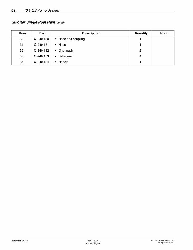
20-Liter Single Post Ram (contd)
Item Part Description Quantity Note
30 Q-240 130 S Hose and coupling 1
31 Q-240 131 S Hose 1
32 Q-240 132 S One touch 2
33 Q-240 133 S Set screw 4
34 Q-240 134 S Handle 1
40:1 QS Pump System 53
E 2000 Nordson CorporationAll rights reserved
334 452AIssued 11/00
Manual 24-14
2414006A
10
9
7
6
5
18
2
17
16
13
12
11
15
4
2
1
3
8
22
23
24
32
27
26
32
20 21
21
19
25
29
31
33
34
2128
30
19
14
Fig. 6 20-Liter Single Post Ram
40:1 QS Pump System54
E 2000 Nordson CorporationAll rights reserved
334 452AIssued 11/00
Manual 24-14
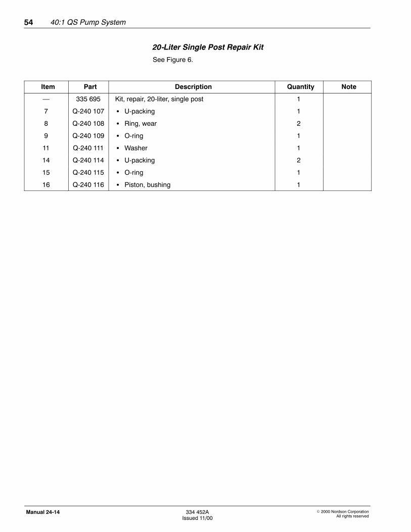
20-Liter Single Post Repair Kit
See Figure 6.
Item Part Description Quantity Note
— 335 695 Kit, repair, 20-liter, single post 1
7 Q-240 107 S U-packing 1
8 Q-240 108 S Ring, wear 2
9 Q-240 109 S O-ring 1
11 Q-240 111 S Washer 1
14 Q-240 114 S U-packing 2
15 Q-240 115 S O-ring 1
16 Q-240 116 S Piston, bushing 1
40:1 QS Pump System 55
E 2000 Nordson CorporationAll rights reserved
334 452AIssued 11/00
Manual 24-14
This section provides general specifications regarding pneumatics,hydraulics, and ram specifications.
NOTE: Because of possible technological or quality improvements,equipment specifications are subject to change without notice.
Pressure Ratio 40:1
Operating Air Pressure 3--6 bar (43--87 psi)
Max. Discharge Pressure 345 bar (5000 psi)
Air Inlet 3/4 in.
Max. Incoming Air Pressure 6 bar (87 psi)
Air Valves stainless steel plate, sliding acetalring
Ram Air Inlet 1/4 npsm (female)
Max. Air Inlet Pressure 10 bar (150 psi)
Pump Stroke 120 mm (4.7 in.)
Max. Delivery 16 l/min (4.2 gal/min)
Max. Pump Speed 80 cycles/min
Fluid Outlet 1 in.
Flow Volume 200 cc/cycle
Air Motor 540 mm (21.25 in.) height
305 mm (12 in.) diameter
Ram raised: 2576 x 1067 x 635 mm
(101.4 x 42 x 25 in.)
lowered:1575 x 1067 x 635 mm(62 x 42 x 25 in.)
Piston Diameter 260 mm (10.2 in.)
Air Motor Stroke Length 121 mm (4.75 in.)
Pump Unit Weight 330 kg (727.5 lb)
Air Motor Weight 34 kg (75 lb)
Mounting Holes 4 x 14.2 mm (0.56 in.)
9. Specifications
Air
Fluid/Pump
Dimensions/Weights
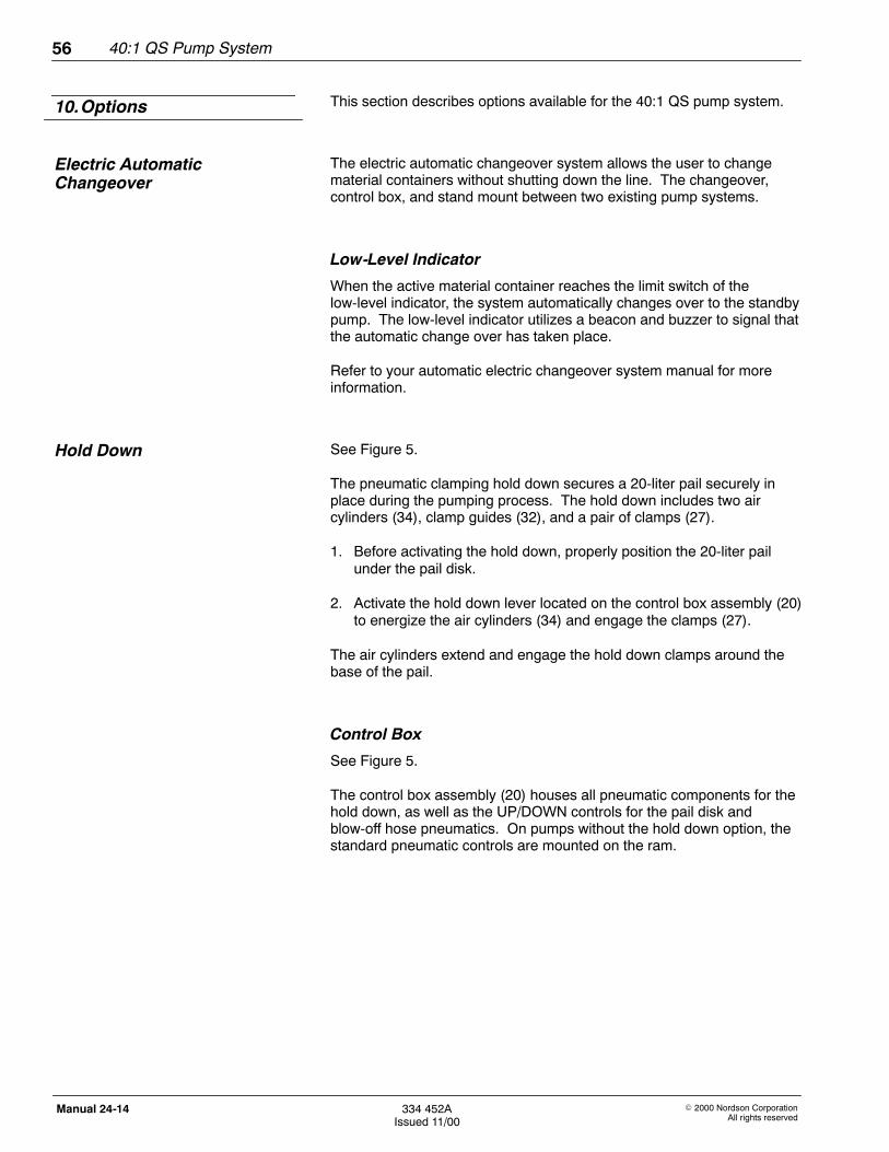
40:1 QS Pump System56
E 2000 Nordson CorporationAll rights reserved
334 452AIssued 11/00
Manual 24-14
This section describes options available for the 40:1 QS pump system.
The electric automatic changeover system allows the user to changematerial containers without shutting down the line. The changeover,control box, and stand mount between two existing pump systems.
Low-Level Indicator
When the active material container reaches the limit switch of thelow-level indicator, the system automatically changes over to the standbypump. The low-level indicator utilizes a beacon and buzzer to signal thatthe automatic change over has taken place.
Refer to your automatic electric changeover system manual for moreinformation.
See Figure 5.
The pneumatic clamping hold down secures a 20-liter pail securely inplace during the pumping process. The hold down includes two aircylinders (34), clamp guides (32), and a pair of clamps (27).
1. Before activating the hold down, properly position the 20-liter pailunder the pail disk.
2. Activate the hold down lever located on the control box assembly (20)to energize the air cylinders (34) and engage the clamps (27).
The air cylinders extend and engage the hold down clamps around thebase of the pail.
Control Box
See Figure 5.
The control box assembly (20) houses all pneumatic components for thehold down, as well as the UP/DOWN controls for the pail disk andblow-off hose pneumatics. On pumps without the hold down option, thestandard pneumatic controls are mounted on the ram.
10.Options
Electric AutomaticChangeover
Hold Down