Embed Size (px)
Citation preview

400.2D EVO 400.4D EVO800.4D EVO 400.4S EVO 800.4S EVO

1 EVO Amplifier
1 Owner’s Manual
1 Allen wrench 2.5mm*
2 Cables for High Input
1 Promotional Sticker
*Only in "S" version

Ø If you have questions about the installation of this equipment, get in touch with our tech support or with a professional specialized in car audio installation;
Ø Before proceeding with the installation of any electric equipment on your vehicle, unplug the negative (-) terminal of the battery to avoid fires, injuries or damages;
Ø Use your sound system safely, exposure to continuous sound pressure over 85dB may cause irreversible hearing loss.
Ø Do not install the amplifier in places exposed to water, dirt or humidity;
Ø To prevent injuries to the user or damage to the amplifier, read all the safety instructions written on this manual;
Ø This equipment is for use in automotive DC voltagebat ter ies, between 12.6 and 14.4 vo l ts . Beforeinstalling the equipment, check the voltage of thebatteries;
Ø Securely mount the amplifier so that it does not come loose in the event of collision or a suddent jolt to the vehicle. Avoid mounting it on mettalicparts of the vehicle, because it may cause an ground loop (you might have noise issues).
SAFETY INSTRUCTIONS
Congratulations on acquiring a product with the highest quality and technology!The SounDigital products are developed to assure maximum efficiency and reability to your sound system.
Dear Customer,
The main characteristics of Class D amplifiers are: audio quality, efficiency, versatility and compact design. Here are the advantages of these characteristics:
Class D Amplifiers:
Audio Quality – Class D amplifiers used to have a limited response in the past and they used to have a worse performance regarding higher frequencies than Class AB amps, despite being more efficient. Introducing new technologies, SounDigital developed a Class D amplifier superior to the Class AB ones in efficiency and performance.
Efficiency – The SounDigital Class D amplifiers have a total efficiency (power source + output) higher than 60%, assuring a battery consumption and a heating lower than the expected.
Versatility of Uses –The flat response of all the frequencies of SounDigital amplifiers allows them to be used in all the kinds of systems: SPL, Sound Quality, Trio Eletrico and Pancadao, meeting the needs with extreme quality.
Compact Design – The high efficiency and technology allow our amplifiers to be really compact, making it easy to install them in vehicles where you have limited space.
IMPORTANT INFORead this manual and follow its instructions and information carefully. It contains extremely important information to have your amplifier working properly. If you feel the need to contact our Tech Support, you can reach our technicians through the e-mail [email protected].
IMPORTANT INFO
To know our complete line of amplifiers and accessories, visit www.soundigitalusa.com.
We recommend the use of SounDigital original accessories for a better performance. The crossovers and voltmeters offered by SounDigital follow the same quality standards as our amplifiers, assuring an excellent quality and high power sound system to our customers.
This “Warning” sign alerts the user of important info. Not following this instructions may cause injuries to the user or damage to the equipment.Warning!
1
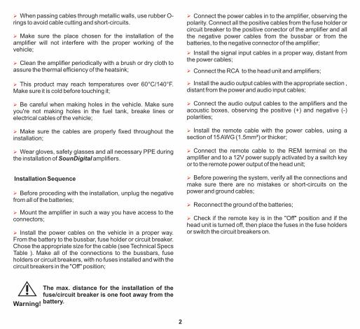
Ø When passing cables through metallic walls, use rubber O-rings to avoid cable cutting and short circuits.-
Ø Make sure the place chosen for the installation of the amplifier will not interfere with the proper working of the vehicle;
Ø Clean the amplifier periodically with a brush or dry cloth to assure the thermal efficiency of the heatsink;
Ø Be careful when making holes in the vehicle. Make sure you're not making holes in the fuel tank, br ake lines or eelectrical cables of the vehicle;
Ø Make sure the cables are properly fixed throughout the ins allationt ;
Ø Wear gloves, safety g s and all necessary PPE during lassethe installation of SounDigital amplifiers.
Ø Before proceding with the installation, unplug the negative from all of the batteries;
Installation Sequence
Ø Mount the amplifier in such a way you have access to the connectors;
Ø This product may reach temperatures over 60°C/140°F. Make sure it is cold before touching it;
Ø Install the power cables on the vehicle in a proper way. From the battery to the bussbar, fuse holder or circuit breaker. Chose the appropriate size for the cable (see Technical Specs Table ). Make all of the connections to the bussbars, fuse holders or circuit breakers, with no fuses installed and with the circuit breakers in the "Off" position;
Ø Connect the audio output cables to the amplifiers and the acoustic boxes, observing the positive (+) and negative (-) polarities;
Ø Install the signal input cables in a proper way, distant from the power cables;
Ø Connect the power cables in to the amplifier, observing the polarity. Connect all the positive cables from the fuse holder or circuit breaker to the positive conector of the amplifier and all the negative power cables from the bussbar or from the batteries, to the negative connector of the amplifier;
Ø Connect the remote cable to the REM terminal on the amplifier and to a 12V power supply activated by a switch key or to the remote power output of the head unit;
Ø Install the remote cable with the power cables, using a section of 15 AWG (1.5mm²) or thicker;
Ø Before powering the system, verify all the connections and make sure there are no mistakes or short-circuits on the power and ground cables;
Ø Reconnect the ground of the batteries;
Ø Install the audio output cables with the appropriate section , distant from the power and audio input cables;
Ø Check if the remote key is in the "Off" position and if the head unit is turned off, then place the fuses in the fuse holders or switch the circuit breakers on.
Ø Connect the RCA to the head unit and amplifiers;
The max. distance for the installation of the fuse/circuit breaker is one foot away from the battery.Warning!
2
PANELS DESCRIPTION
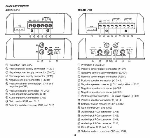
400.2D EVO
1 Protection Fuse 30A;
2 Positive power supply connector (+12V);
3 Negative power supply connector (GND);
4 Remote power supply connector (REM);
5 Negative speaker connector (-) CH1;
6 Positive speaker connector(+) CH1 and negative (-) CH2;
7 Positive speaker connector (+) CH2;
Audio input RCA connector CH1;8
11 Selector switch crossover CH1 and CH2.
9 Audio input RCA connector CH2;
10 Gain control CH1 and CH2;
18 Selector switch crossover CH3 and CH4.
17 Gain Control CH3 and CH4;
16 Audio input RCA connector CH3;
Positive speaker connector (+) CH4;10
15 Audio input RCA connector CH4;
14 Audio input RCA connector CH2;
13 Audio input RCA connector CH1;
12 Gain control CH1 and CH2;
11 Selector switch crossover CH1 e CH2;
400.4D EVO
Protection Fuse 30A;1
9 Positive speaker connector (+) CH3 and negative (-) CH4;
8 Negative speaker connector (-) CH3;
7 Negative speaker connector (-) CH2;
6 Negatiive speaker connector (-) CH1 and positive (+) CH2;
5 Positive speaker connector (+) CH1;
4 Remote power supply connector (REM);
3 Negative power supply connector (GND);
2 Positive power supply connector (+12V);
CH2 CH4
CH1 CH3
CONTROLS
LP HPFULL
X-OVER
CONTROLS
GAIN
LP HPFULL
X-OVERGAIN
1817161514131211
+12V GND REMCH1 CH3CH2 CH4
+ - -+
BRIDGE
FUSE
BRIDGE
3
+-- +
1 2 4 5 6 8 9 107
3
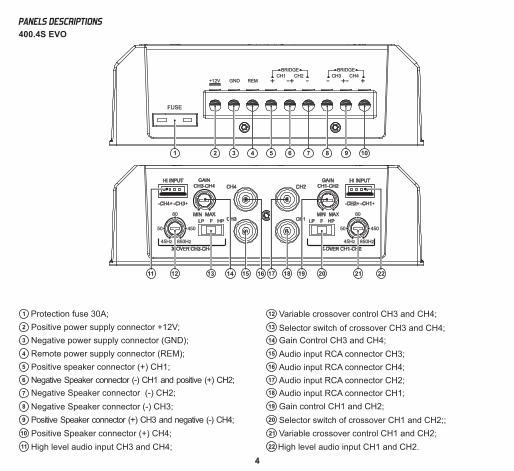
Positive Speaker connector (+) CH4;10
11 High level audio input CH3 and CH4;
Protection fuse 30A;1
9 Positive Speaker connector (+) CH3 and negative (-) CH4;
8 Negative Speaker connector (-) CH3;
7 Negative Speaker connector (-) CH2;
6 Negative Speaker connector (-) CH1 and positive (+) CH2;
5 Positive speaker connector (+) CH1;
4 Remote power supply connector (REM);
3 Negative power supply connector (GND);
2 Positive power supply connector +12V;
18 Audio input RCA connector CH1;
17 Audio input RCA connector CH2;
16 Audio input RCA connector CH4;
15 Audio input RCA connector CH3;
14 Gain Control CH3 and CH4;
13 Selector switch of crossover CH3 and CH4;
12 Variable crossover control CH3 and CH4;
19 Gain control CH1 and CH2;
20 Selector switch of crossover CH1 and CH2;;
21 Variable crossover control CH1 and CH2;
22 High level audio input CH1 and CH2.
+12V GND REMCH1 CH3CH2 CH4
+ - -+
BRIDGE
FUSE
BRIDGE
3
+-- +
1 2 4 5 6 8 9 107
50
850Hz45Hz
450
80
50
850Hz45Hz
450
80
17 18161512 212013 1411 19 22
400.4S EVO
PANELS DESCRIPTIONS
4
CH2 CH4
CH1 CH3
CONTROLS CONTROLS
GAIN
LP HPFULL
X-OVER
LP HPFULL
X-OVERGAIN
191817161513
732 4 5 6 8 9 101
12 14
11
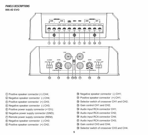
Positive speaker connector (+) CH4;1
9 Positive speaker connector (+) CH2;
8 Negative speaker connector (-) CH2;
7 Remote power supply connector (REM);
6 Negative power supply connector (GND);
5 Positive power supply connector (+12V);
4 Negative speaker connector (-) CH3;
3 Positive speaker connector (+) CH3;
2 Negative speaker connector (-) CH4;
Negative speaker connector (-) CH1;10
19 Selector switch of crossover CH3 and CH4.
18 Gain control CH3 and CH4;
17 Audio input RCA connector CH3;
16 Audio input RCA connector CH4;
15 Audio input RCA connector CH2;
14 Audio input RCA connector CH1;
13 Gain control CH1 and CH2;
12 Selector switch of crossover CH1 and CH2;
11 Positive speaker connector (+) CH1;
800.4D EVO
PANELS DESCRIPTIONS
5
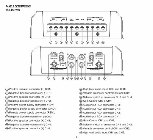
Negative Speaker connector (-) CH4;10
18
17
16
15
14
13
12
11 Positive speaker connector (+) CH4;
Positive Speaker connector (+) CH1;1
9 Positive speaker connector (+) CH3;
8 Negative Speaker connector (-) CH3;
7 Remote power supply connector (REM);
6 Negative power supply connector (GND);
5 Positive power supply connector +12V;
4 Negative Speaker connector (-) CH2;
3 Positive speaker connector (+) CH2;
2 Negative Speaker connector (-) CH1;
19
20
21
22
Audio input RCA connector CH1;
Audio input RCA connector CH2;
Audio input RCA connector CH4;
Audio input RCA connector CH3;
Gain Control CH3 e CH4;
Selector switch of crossover CH3 and CH4;
Variable crossover control CH3 and CH4;
Gain Control CH1 and CH2;
Selector switch of crossover CH1 and CH2;
Variable crossover control CH1 and CH2;
High level audio input CH1 and CH2.
High level audio input CH3 and CH4;
23
50
850Hz45Hz
450
80
50
850Hz45Hz
450
80
18 19171613 222114 1512 20 23
732 4 5 6 8 9 101 11
800.4S EVO
PANELS DESCRIPTIONS
7
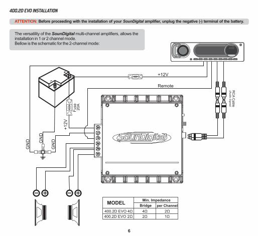
ATTENTION: Before proceeding with the installation of your SounDigital amplifier, unplug the negative (-) terminal of the battery.
The versatility of the SounDigital multi-channel amplifiers, allows the installation in 1 or 2 channel mode.Bellow is the schematic for the 2-channel mode:
RC
A C
able
(Audio
Sig
nal)
Fuse
20A
MODEL
4 Ω
2 Ω
2Ω
1Ω400.2D EVO
400.2D EVO 4 Ω
2Ω
Min. Impedance
Bridge per Channel
400.2D EVO INSTALLATION
6
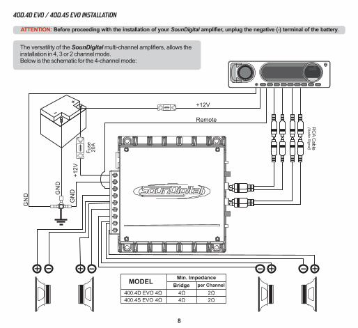
400.4D EVO / 400.4S EVO INSTALLATION
Fu
se2
0A
ATTENTION: Before proceeding with the installation of your SounDigital amplifier, unplug the negative (-) terminal of the battery.
The versatility of the SounDigital multi-channel amplifiers, allows the installation in 4, 3 or 2 channel mode.Below is the schematic for the 4-channel mode:
RC
A C
able
(Audio
Sig
nal)
MODELMin. Impedance
Bridge per Channel
4
4
Ω
Ω
2
2
Ω
Ω
400.4D EVO
400.4S EVO
4
4
Ω
Ω
8
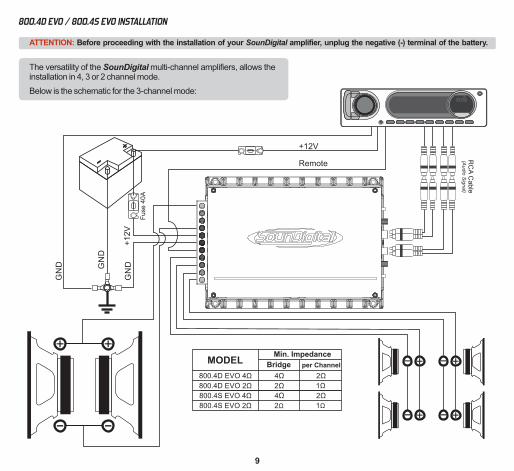
The versatility of the SounDigital multi-channel amplifiers, allows the installation in 4, 3 or 2 channel mode.
Below is the schematic for the 3-channel mode:
ATTENTION: Before proceeding with the installation of your SounDigital amplifier, unplug the negative (-) terminal of the battery.
800.4D EVO / 800.4S EVO INSTALLATION
Fu
se 4
0A
MODELMin. Impedance
Bridge per Channel
4
4
Ω
Ω
2
2
Ω
Ω
1
1
Ω
Ω
2
2
Ω
Ω
800.4D EVO 4Ω
800.4S EVO 4Ω
800.4D EVO 2Ω
800.4S EVO 2Ω
RC
A C
able
(Audio
Sig
nal)
9
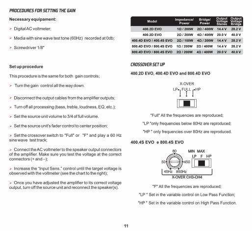
INPUT CONNECTIONS
Hi Inputs (400.4S EVO and 800.4S EVO)
+12V GND REM +
+12V GND REM +
XXX
Ø High input must be used when the main unit does not have RCA outputs.
Ø When high inputs is used, no remote connection is required, the amplifier recognizes the audio signal and switches on.
Ø If your source unit is not able to turn on the amplifier through the high level input, the remote input should be connected normally.
RCA and hi inputs should not be used simultaneously or you may damage the amplifier.Warning!
RC
A C
ab
le(A
udio
Sig
nal)
RCA Inputs
0dB
-12dB
dB
Hz
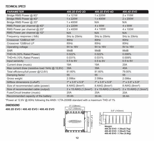
Ø Switch key at "HP" - Set in the variable control between 45Hz and 850Hz ("A") where you want to perform the high pass cut filter;
Ø Switch key at "LP" - Set in the variable control between 45Hz and 850Hz ("B") where you want to perform the low pass cut filter;
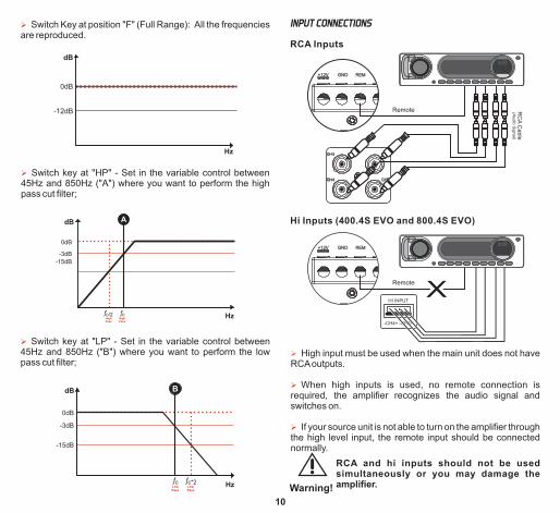
Ø Switch Key at position "F" (Full Range): All the frequencies are reproduced.
-3dB
c/2ƒHighPass
cƒHighPass
A
0dB
-15dB
dB
Hz
-3dB
0dB
-15dB
LowPass
B
cƒ c*2ƒLowPass
dB
Hz
10
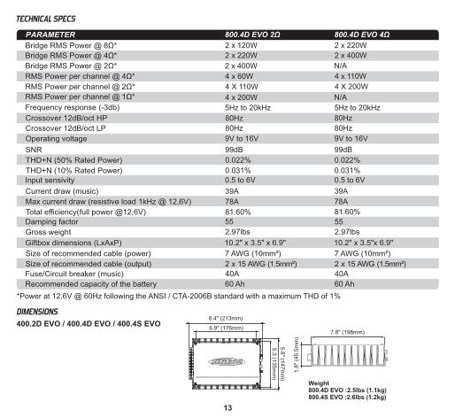
CROSSOVER SET UP
400.2D EVO, 400.4D EVO and 800.4D EVO
"Full" All the frequencies are reproduced;
"LP "only frequencies below 80Hz are reproduced;
"HP " only frequencies over 80Hz are reproduced.
Ø Set the source unit's fader control to center position;
This procedure is the same for both gain controls;
Ø Screwdriver 1/8"
Ø Digital AC voltmeter;
PROCEDURES FOR SETTING THE GAIN
Necessary equipament:
Ø Turn the gain control all the way down.
Set up procedure
Ø Disconnect the output cables from the amplifier outputs;
Ø Turn off all processing (bass, treble, loudness, EQ, etc.);
Ø Media with sine wave test tone (60Hz) recorded at 0db;
Ø Set the source unit volume to 3/4 of full volume.
Ø Set the crossover switch to "Full" or "F" and play a 60 Hz sine wave test track;
Ø Once you have adjusted the amplifier to its correct voltage output, turn off the source unit and reconnect the speaker(s).
Ø Increase the “Input Sens.” control until the target voltage is observed with the voltmeter (see the chart to the right);
Ø Connect the AC voltmeter to the speaker output connectors of the amplifier. Make sure you test the voltage at the correct connectors (+ and –);
4Ω / 200W
2Ω / 400W
4Ω / 400W
4Ω / 400W
2Ω / 400W
Bridge/Power
Impedance/Power
2Ω / 100W
1Ω / 200W
2Ω / 200W
2Ω / 200W
1Ω / 200W
Model
400.4D EVO / 400.4S EVO
800.4D EVO / 800.4S EVO
800.4D EVO / 800.4S EVO
400.2D EVO
400.2D EVO
14.4 V
14.4 V
20.0 V
20.0 V
14.4 V
VoltageOutput
Stereo
28.2 V
28.2 V
40.0 V
40.0 V
28.2 V
VoltageOutput
Bridge
400.4S EVO e 800.4S EVO
"F" All the frequencies are reproduced;
"LP " Set in the variable control on Low Pass Function;
"HP " Set in the variable control on High Pass Function.
50
850Hz45Hz
450
80
11
4.2" (106mm)
5" (128mm)
5.4
" (13
8m
m )
(5")1
26
mm
5.6" (143mm)
1.8
" (4
5.5
mm
)
Weight: 400.2D EVO :1.5lbs(0.7kg)400.4D EVO :1.5lbs(0.7kg)400.4S EVO :1.7lbs (0.8kg)
12
TECHNICAL SPECS
*Power at 12.6V @ 60Hz following the ANSI / CTA-2006B standard with a maximum THD of 1%
400.2D EVO 2Ω
1 x 121W
1 x 220W
1 x 400W
2 x 220W
2 x 400W
N/A
5Hz to 20kHz
80Hz
9V to 16V
99dB
0.022%
0.031%
0.5 to 6V
19A
39A
81.60%
7" x 3.5" x 5.9"
8 AWG (8mm²)
2 x 15 AWG (1,5mm²)
20A
35 Ah
2.09lbs
80Hz
400.2D EVO 4Ω
1 x 220W
1 x 400W
N/A
4 x 55W
4 x 100W
N/A
5Hz to 20kHz
80Hz
9V to 16V
99dB
0.022%
0.031%
0.5 to 6V
19A
39A
81.60%
55
7" x 3.5" x 5.9"
8 AWG (8mm²)
2 x 15 AWG (1,5mm²)
20A
35 Ah
2.09lbs
80Hz
400.4D EVO
2 x 110W
2 x 200W
N/A
4 x 55W
4 x 100W
N/A
5Hz to 20kHz
80Hz
9V to 16V
88dB
0.006%
0.009%
0.5 to 6V
20A
40A
79.00%
55
7" x 3.5" x 5.9"
8 AWG (8mm²)
2 x 15 AWG (1,5mm²)
20A
35 Ah
2.09lbs
80Hz
DIMENSIONS
400.2D EVO / 400.4D EVO / 400.4S EVO
55
PARAMETER
Bridge RMS Power @ 8Ω*
Bridge RMS Power @ 4Ω*
Bridge RMS Power @ 2Ω*
RMS Power per channel @ 4Ω*
RMS Power per channel @ 2Ω*
RMS Power per channel @ 1Ω*
Frequency response (-3db)
Crossover 12dB/oct HP
Operating voltage
SNR
THD+N (50% Rated Power)
THD+N (10% Rated Power)
Input sensivity
Current draw (music)
Max current draw (resistive load 1kHz @ 12,6V)
Total efficiency(full power @12,6V)
Damping factor
Gross weight
Giftbox dimensions (LxAxP)
Size of recommended cable (power)
Size of recommended cable (output)
Fuse/Circuit breaker (music)
Recommended capacity of the battery
Crossover 12dB/oct LP
*Power at 12.6V @ 60Hz following the ANSI / CTA-2006B standard with a maximum THD of 1%
TECHNICAL SPECS
13
800.4D EVO 2Ω
2 x 120W
2 x 220W
2 x 400W
4 x 60W
4 X 110W
4 x 200W
5Hz to 20kHz
9V to 16V
99dB
0.5 to 6V
39A
78A
81.60%
55
10.2" x 3.5" x 6.9"
7 AWG (10mm²)
2 x 15 AWG (1.5mm²)
40A
60 Ah
2.97lbs
80Hz
80Hz
800.4D EVO 4Ω
2 x 220W
2 x 400W
N/A
4 x 110W
4 X 200W
N/A
5Hz to 20kHz
80Hz
9V to 16V
99dB
0.5 to 6V
39A
78A
81.60%
55
10.2" x 3.5"x 6.9"
7 AWG (10mm²)
2 x 15 AWG (1.5mm²)
40A
60 Ah
2.97lbs
80Hz
DIMENSIONS
400.2D EVO / 400.4D EVO / 400.4S EVO 6.9" (176mm)
7.8" (198mm)
5.8
" (147m
m)
5.3
(135m
m)
8.4" (213mm)
1.8
" (4
5.5
mm
)
Weight 800.4D EVO :2.5lbs (1.1kg)800.4S EVO :2.6lbs (1.2kg)
PARAMETER
Bridge RMS Power @ 8Ω*
Bridge RMS Power @ 4Ω*
Bridge RMS Power @ 2Ω*
RMS Power per channel @ 4Ω*
RMS Power per channel @ 2Ω*
RMS Power per channel @ 1Ω*
Frequency response (-3db)
Crossover 12dB/oct HP
Operating voltage
SNR
Input sensivity
Current draw (music)
Max current draw (resistive load 1kHz @ 12,6V)
Total efficiency(full power @12,6V)
Damping factor
Gross weight
Giftbox dimensions (LxAxP)
Size of recommended cable (power)
Size of recommended cable (output)
Fuse/Circuit breaker (music)
Recommended capacity of the battery
Crossover 12dB/oct LP
0.022%
0.031%
0.022%
0.031%
THD+N (50% Rated Power)
THD+N (10% Rated Power)

*Power at 12.6V @ 60Hz following the ANSI / CTA-2006B standard with a maximum THD of 1%
400.4S EVO
2 x 110W
2 x 200W
N/A
4 x 55W
4 x 100W
N/A
5Hz to 20kHz
45Hz to 850Hz
45Hz to 850Hz
9V to 16V
88dB
0.5 to 6V
20A
40A
79.00%
55
7" x 3.5" x 5.9"
8 AWG (8mm²)
2 x 15 AWG (1,5mm²)
20A
35 Ah
2,09lbs
800.4S EVO 2Ω
2 x 120W
2 x 220W
2 x 400W
4 x 60W
4 X 110W
4 x 200W
5Hz to 20kHz
45Hz to 850Hz
45Hz to 850Hz
9V to 16V
99dB
0.5 to 6V
39A
78A
81.60%
55
10.2" x 3.5" x 6.9"
7 AWG (10mm²)
2 x 15 AWG (1.5mm²)
40A
60 Ah
2.97lbs
800.4S EVO 4Ω
2 x 220W
2 x 400W
N/A
4 x 110W
4 X 200W
N/A
5Hz to 20kHz
LP - 45Hz to 850Hz
HP - 45Hz to 850Hz
9V to 16V
99dB
0.5 to 6V
39A
78A
81.60%
55
10.2" x 3.5"x 6.9"
7 AWG (10mm²)
2 x 15 AWG (1.5mm²)
40A
60 Ah
2.97lbs
TECHNICAL SPECS
14
PARAMETER
Bridge RMS Power @ 8Ω*
Bridge RMS Power @ 4Ω*
Bridge RMS Power @ 2Ω*
RMS Power per channel @ 4Ω*
RMS Power per channel @ 2Ω*
RMS Power per channel @ 1Ω*
Frequency response (-3db)
Crossover 12dB/oct HP
Operating voltage
SNR
Input sensivity
Current draw (music)
Max current draw (resistive load 1kHz @ 12,6V)
Total efficiency(full power @12,6V)
Damping factor
Gross weight
Giftbox dimensions (LxAxP)
Size of recommended cable (power)
Size of recommended cable (output)
Fuse/Circuit breaker (music)
Recommended capacity of the battery
Crossover 12dB/oct LP
THD+N (50% Rated Power)
THD+N (10% Rated Power)
0.006%
0.009%
0.022%
0.031%
0.022%
0.031%
Ø Exposure to adverse conditions (weather, humidity, etc.);
Ø Damage caused by fall, impact or natural depreciation, caused by transport and/or handling, risks or smashing's;
Ø Product was purchased more than 12 months ago.
Ø Incorrect installation or non-conformity with the Manual;
Ø Maintenance made by unauthorized personnel;
Ø Alteration or removal of the seal/serial number;
Ø In case of manufacturing defect or bad quality of raw material the max compensation will be the replacement of the product,
not allowing any kind of compensation payment;
Warranty Covers:
Ø Component or material with manufacturing defects;
Ø New modifications/iterations on a product don't obligate the manufacturer to modify products formerly produced.
Ø Any extra information you can get by contacting us at the e-mail address: [email protected];
Ø Workmanship/service needed to repair the equipment;
Observations:
LIMITED WARRANTY
SounDigital warrants the original purchaser that this product shall be free of defects in materials an workmanship for a period of twelve (12) months from the original date of purchase. Some countries have extended warranty in case the product is installed by an authorized dealer. This warranty is not transferrable and applies only to the original customer from an authorized SounDigital dealer.
15


![blog. · Web viewANSWER: B ANSWER: C [CI`(H2O)4C1(NO2)]CI COON HOOC-CH2\N_CCH~_CH___N/H Ml ` | ` \' ' CH2 CH2 -COOH HOOC' HOOC`.."CHZ CH2"COOH \ I /N-CH2-CH2-N\ HOOC""CH2 CH2-COOH](https://img.dokumen.tips/doc/110x75/5ab561c67f8b9a0f058cbd1a/blog-viewanswer-b-answer-c-cih2o4c1no2ci-coon-hooc-ch2ncchchnh.jpg)


![Synthesis of Novel Electrically Conducting Polymers: Potential ... · PPh3 + Br(CH2). CO2Me ..... > [Ph3P--CH2(CH2). i CO2Me]*Br* [phaP--CH2(CH2)n__CO2Mel*Br -Z--BuL>_phaP=CH (C H2)n_i](https://img.dokumen.tips/doc/110x75/5ebc39ab077be8135d1c1d2a/synthesis-of-novel-electrically-conducting-polymers-potential-pph3-brch2.jpg)