Embed Size (px)
Citation preview

4” and 6” Suspension Systems
Chevy/GMC 1500 4WD Pickup | 2014-2018
Rev. 010818
Part#: 021663
491 W. Garfield Ave., Coldwater, MI 49036 . Phone: 517-279-2135E-mail: [email protected]

2 | 021663
Read And Understand All Instructions And Warnings Prior To Installation Of
System And Operation Of Vehicle.
BEFORE YOU STARTBDS Suspension Co. recommends this system be installed by a professional technician. In addition to these instructions, professional knowledge of disassembly/ reassembly procedures and post installation checks must be known.
In an effort to reduce the risk of rollover crashes the National Highway Traffic Safety Administration (NHTSA) established the Federal Motor Vehicle Safety Standard (FMVSS) No. 126 requiring all new passenger vehicles under 10,000 lbs GVWR include an electronic stability control (ESC) system as standard equipment. Effective August 2012 this law requires aftermarket products to be compliant with these same standards.
Your truck is about to be fitted with the best suspension system on the market today. That means you will be driving the baddest looking truck in the neighborhood, and you’ll have the warranty to ensure that it stays that way for years to come.
Thank you for choosing BDS Suspension!
Perform steering sweep to ensure front brake hoses have adequate slack and do not contact any rotating, mobile or heated members. Inspect rear brake hoses at full extension for adequate slack. Failure to perform hose check/ replacement may result in component failure. Longer replacement hoses, if needed can be purchased from a local parts supplier.
Perform head light check and adjustment.
Re-torque all fasteners after 500 miles. Always inspect fasteners and components during routine servicing.
FOR YOUR SAFETYCertain BDS Suspension products are intended to improve off-road performance. Modifying your vehicle for off-road use may result in the vehicle handling differently than a factory equipped vehicle. Extreme care must be used to prevent loss of control or vehicle rollover. Failure to drive your modified vehicle safely may result in serious injury or death. BDS Suspension Co. does not recommend the combined use of suspension lifts, body lifts, or other lifting devices. You should never operate your modified vehicle under the influence of alcohol or drugs. Always drive your modified vehicle at reduced speeds to ensure your ability to control your vehicle under all driving conditions. Always wear your seat belt.
BEFORE INSTALLATIONSpecial literature required: OE Service Manual for model/year of vehicle. Refer to manual for proper disassembly/reassembly procedures of OE and related components.
Adhere to recommendations when replacement fasteners, retainers and keepers are called out in the OE manual.
Larger rim and tire combinations may increase leverage on suspension, steering, and related components. When selecting combinations larger than OE, consider the additional stress you could be inducing on the OE and related components.
Post suspension system vehicles may experience drive line vibrations. Angles may require tuning, slider on shaft may require replacement, shafts may need to be lengthened or trued, and U-joints may need to be replaced.
Secure and properly block vehicle prior to installation of BDS Suspension components. Always wear safety glasses when using power tools.
If installation is to be performed without a hoist, BDS Suspension Co. recommends rear alterations first.
Due to payload options and initial ride height variances, the amount of lift is a base figure. Final ride height dimensions may vary in accordance to original vehicle attitude. Always measure the attitude prior to beginning installation.
BEFORE YOU DRIVECheck all fasteners for proper torque. Check to ensure for adequate clearance between all rotating, mobile, fixed, and heated members. Verify clearance between exhaust and brake lines, fuel lines, fuel tank, floor boards and wiring harness. Check steering gear for clearance. Test and inspect brake system.
Visit 560plus.com for more information.
FITMENT GUIDE 6”Lift:33 x 12.50 on 17x8 w/ 4.5” BS34 x 12.50 on 17x9, 18x9 w/ 5” BS35 x 12.50 on 20x9 w/ 5.75” BS
4”Lift:33 x 12.50 on 17x9, 18x9 w/ 5” BS35 x 12.50 on 20x9 w/ 5.75” BS
021663 | 3
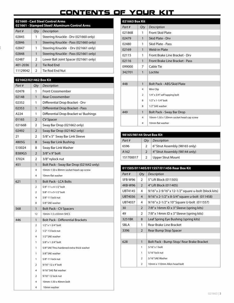
021660 - Cast Steel Control Arms021661 - Stamped Steel/ Aluminum Control Arms
Part # Qty Description
02845 1 Steering Knuckle - Drv (021660 only)
02846 1 Steering Knuckle - Pass (021660 only)
02847 1 Steering Knuckle - Drv (021661 only)
02848 1 Steering Knuckle - Pass (021661 only)
02487 2 Lower Ball Joint Spacer (021661 only)
401-2036 2 Tie Rod End
11129042 2 Tie Rod End Nut
021662/021462 Box Kit
Part # Qty Description
02478 1 Front Crossmember
02148 1 Rear Crossmember
02352 1 Differential Drop Bracket - Drv
02353 1 Differential Drop Bracket - Pass
A224 1 Differential Drop Bracket w/ Bushings
01165 2 CV Spacer
02166B 2 Sway Bar Drop (021662 only)
02492 2 Sway Bar Drop (021462 only)
21 2 5/8” x 5” Sway Bar Link Sleeve
4805G 8 Sway Bar Link Bushing
S10024 8 Sway Bar Link Washer
B389G5 2 3/8” x 9” bolt
37024 2 3/8” nylock nut
451 1 Bolt Pack - Sway Bar Drop (021642 only)4 10mm-1.50 x 80mm socket head cap screw
4 10mm flat washer
621 1 Bolt Pack - LCA Bolts2 5/8”-11 x 4-1/2” bolt
2 5/8”-11 x 5-1/2” bolt
4 5/8”-11 lock nut
8 5/8” SAE washer
568 1 Bolt Pack - CV Spacers12 10mm-1.5 x 65mm SHCS
446 1 Bolt Pack - Differential Brackets2 1/2” x 1-3/4” bolt
2 1/2”-13 lock nut
4 1/2” SAE washer
1 5/8” x 1-3/4” bolt
1 5/8” SAE Thru hardened extra thick washer
1 5/8” SAE washer
1 5/8”-11 lock nut
2 9/16”-12 x 4” bolt
4 9/16” SAE flat washer
2 9/16”-12 lock nut
4 10mm-1.50 x 40mm bolt
4 10mm washer
021663 Box Kit
Part # Qty Description
02186B 1 Front Skid Plate
02479 1 Skid Plate - Drv
02480 1 Skid Plate - Pass
02169 1 Weld-in Plate
02115 1 Front Brake Line Bracket - Drv
02116 1 Front Brake Line Bracket - Pass
099000 7 Cable Tie
342701 1 Loctite
448 1 Bolt Pack - ABS/Skid Plate4 Wire Clip
2 1/4” x 3/4” self tapping bolt
8 1/2” x 1-1/4” bolt
8 1/2” SAE washer
449 1 Bolt Pack - Sway Bar Drop4 10mm-1.50 x 120mm socket head cap screw
4 10mm flat washer
98165/98144 Strut Box Kit
Part # Qty Description
6596 2 6” Strut Assembly (98165 only)
A162 2 4” Strut Assembly (98144 only)
151700017 2 Upper Strut Mount
011505/011405/011557/011456 Rear Box Kit
Part # Qty Description
5FB-W96 2 5” Lift Block (011505)
4KB-W96 2 4” Lift Block (011405)
UBT4145 4 9/16” x 2-9/16” x 12-1/2” square u-bolt (block kits)
UBT4036 4 9/16” x 2-1/2” x 8-3/4” square u-bolt (011458)
UBT4037 4 9/16” x 2-1/2” x 10” Square U-bolt (011557)
30 2 7/8” x 16mm ID x 3” Sleeve (spring kits)
49 2 7/8” x 14mm ID x 3” Sleeve (spring kits)
3251BK 8 Leaf Spring Eye Bushing (spring kits)
SBLA 1 Rear Brake Line Bracket
3396 2 Rear Bump Stop Spacer
628 1 Bolt Pack - Bump Stop/ Rear Brake Bracket1 5/16” x 1 bolt
1 5/16” lock nut
2 5/16” SAE Washer
2 10mm x 110mm Allen head bolt

4 | 021663
021663 | 5
MEASURE FIRSTMeasure from the center of the wheel up to the bottom edge of the wheel opening:
LF__________ RF__________
LR__________ RR__________
DO YOU KNOW IF YOUR TRUCK HAS CAST STEEL OR ALUMINUM/STAMPED STEEL CONTROL ARMS?Verify whether the truck has cast steel or aluminum/stamped steel control arms. This kit is specific for each type of steering knuckles due to differences in balljoint taper.
Vehicles equipped with aluminum or stamped steel control arms use box kit 021661.
Vehicles equipped with cast steel control arms use box kit 021660.
MAGNERIDE EQUIPPED NOTICEFor MagneRide Equipped trucks, disregard these instructions and refer to the instructions in the MagneRide Box Kit 121655.
RECALL NOTICEGM issued a safety recall (#42190) for some 2016-17 vehicles built before 4/8/16 that were equipped with stamped steel upper control arms due to poor weld quality. BDS strongly recommends checking if your vehicle is included in the recall and having the fix performed before installing this suspension system.
WELDING IS REQUIREDThe installation of this kit requires minor welding of a reinforcement plate. We recommend this procedure be performed by an experienced welder. If necessary, this kit can be completely installed and then driven to a shop to have the plate welded. This method will make reaching the weld locations slightly more difficult but it can be done if necessary.
FRONT DISASSEMBLY1. Park the vehicle on a clean, flat surface and block the rear wheels for safety.
2. Disconnect the positive and negative battery cables from the battery.
3. Raise the front of the vehicle with a hydraulic jack and support the frame with jack stands. Remove the wheels.
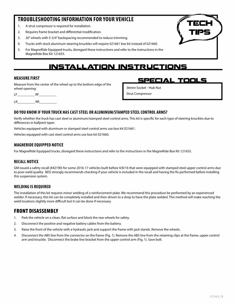
4. Disconnect the ABS line from the connector on the frame (Fig. 1). Remove the ABS line from the retaining clips at the frame, upper control arm and knuckle. Disconnect the brake line bracket from the upper control arm (Fig. 1). Save bolt.
TROUBLESHOOTING INFORMATION FOR YOUR VEHICLE1. A strut compressor is required for installation.
2. Requires frame bracket and differential modification.
3. 20” wheels with 5-3/4” backspacing recommended to reduce trimming.
4. Trucks with stock aluminum steering knuckles will require 021661 box kit instead of 021660.
5. For MagneRide Equipped trucks, disregard these instructions and refer to the instructions in the MagneRide Box Kit 121655.
36mm Socket - Hub Nut
Strut Compressor
6 | 021663
FIGURE 1
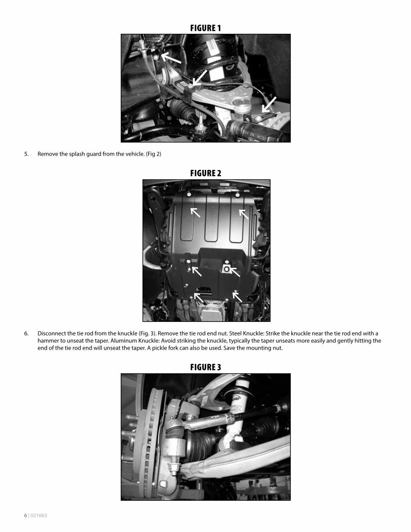
5. Remove the splash guard from the vehicle. (Fig 2)
FIGURE 2
6. Disconnect the tie rod from the knuckle (Fig. 3). Remove the tie rod end nut. Steel Knuckle: Strike the knuckle near the tie rod end with a hammer to unseat the taper. Aluminum Knuckle: Avoid striking the knuckle, typically the taper unseats more easily and gently hitting the end of the tie rod end will unseat the taper. A pickle fork can also be used. Save the mounting nut.
FIGURE 3

021663 | 7
7. Remove the two brake caliper mounting bolts and remove the caliper from the knuckle (Fig. 4). Hang the caliper securely out of the way DO NOT hang the caliper by the brake hose. Save caliper bolts.
FIGURE 4
8. Remove the brake rotor retaining bolt and remove the rotor from the vehicle.
9. Remove the hub dust cap (Fig. 5). Remove the axle shaft nut. Retain nut and cap.
Use a small chisel and hammer to carefully separate the edge of the cap from the hub. Work around the circumference of the cap. The axle nut will require a 36mm socket.
FIGURE 5
8 | 021663
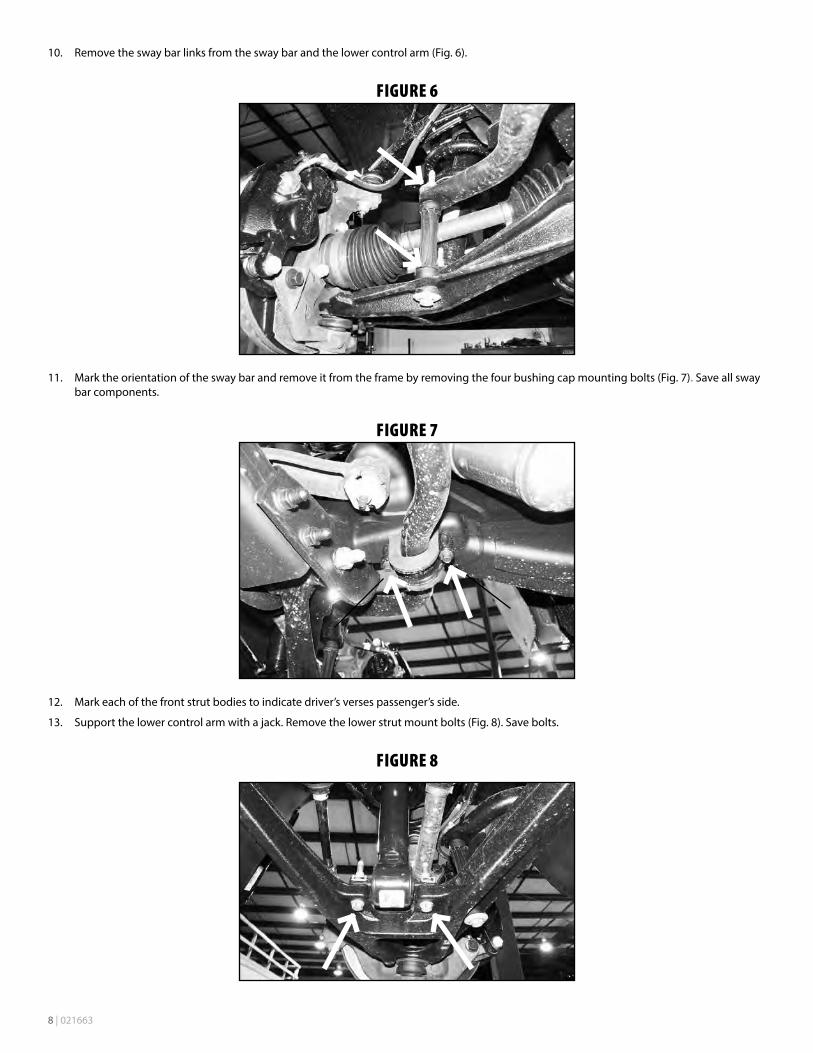
10. Remove the sway bar links from the sway bar and the lower control arm (Fig. 6).
FIGURE 6
11. Mark the orientation of the sway bar and remove it from the frame by removing the four bushing cap mounting bolts (Fig. 7). Save all sway bar components.
FIGURE 7
12. Mark each of the front strut bodies to indicate driver’s verses passenger’s side.
13. Support the lower control arm with a jack. Remove the lower strut mount bolts (Fig. 8). Save bolts.
FIGURE 8

021663 | 9
14. Remove the CV shaft mounting flange bolts (6 per side) (Fig. 9). Mark the shaft to indicate driver’s or passenger’s side. Bolts will not be reused.
FIGURE 9
15. Remove the upper and lower ball joint nuts and thread back on by hand a couple of turns. Steel Knuckle: Strike the knuckle near the upper and lower ball joints to dislodge the tapered seat. Aluminum Knuckle: Avoid striking the knuckle to release the taper, a pickle fork or pry bar can be used to apply a splitting force. Gently hit the end of the ball joint to get it to release. If you do resort to hitting the knuckle avoid re-use and discard.
16. Remove the upper ball joint nut and lower the lower control arm down. Remove the CV shaft from the hub and set aside. Remove the lower ball joint nut and remove the knuckle assembly from the lower control arm. Save ball joint nuts.
17. Remove the three upper strut mounting nuts (Fig. 10) and remove the strut from the vehicle. DO NOT remove the center strut rod nut, it is under extreme pressure. Save nuts.
FIGURE 10
18. Remove the front and rear lower control arm mounting bolts and remove the lower control arm from the vehicle. Save mounting hardware and control arms.

10 | 021663
19. Remove the crossmember struts. (Fig 11)
FIGURE 11
20. Remove the factory rear crossmember from the vehicle by removing the 4 bolts. (Fig 12) Crossmember and hardware will not be reused.
FIGURE 12
21. Make an alignment mark to show the relationship between the front driveshaft and the differential yoke. Remove the four driveshaft bolts and disconnect the driveshaft from the differential. Save bolts. (Fig. 13)
FIGURE 13
021663 | 11
22. The driver’s side rear lower control arm pocket must be cut to provide clearance for the front differential in the relocated position. This also aids in the removal of the differential. This area needs to be cleaned of any oil, grease and/or undercoating. These coatings are flammable.
A putty knife and parts cleaning solvent work well to remove undercoating.
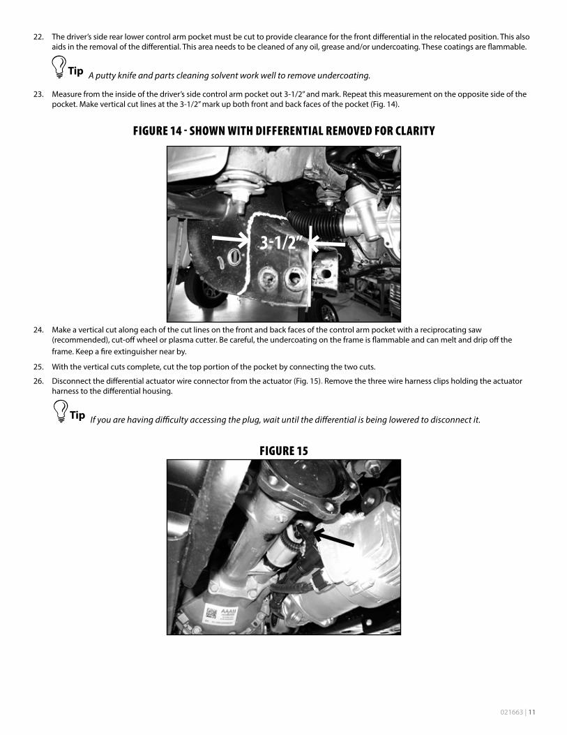
23. Measure from the inside of the driver’s side control arm pocket out 3-1/2” and mark. Repeat this measurement on the opposite side of the pocket. Make vertical cut lines at the 3-1/2” mark up both front and back faces of the pocket (Fig. 14).
FIGURE 14 - SHOWN WITH DIFFERENTIAL REMOVED FOR CLARITY
3-1/2”
24. Make a vertical cut along each of the cut lines on the front and back faces of the control arm pocket with a reciprocating saw (recommended), cut-off wheel or plasma cutter. Be careful, the undercoating on the frame is flammable and can melt and drip off the frame. Keep a fire extinguisher near by.
25. With the vertical cuts complete, cut the top portion of the pocket by connecting the two cuts.
26. Disconnect the differential actuator wire connector from the actuator (Fig. 15). Remove the three wire harness clips holding the actuator harness to the differential housing.
If you are having difficulty accessing the plug, wait until the differential is being lowered to disconnect it.
FIGURE 15
12 | 021663
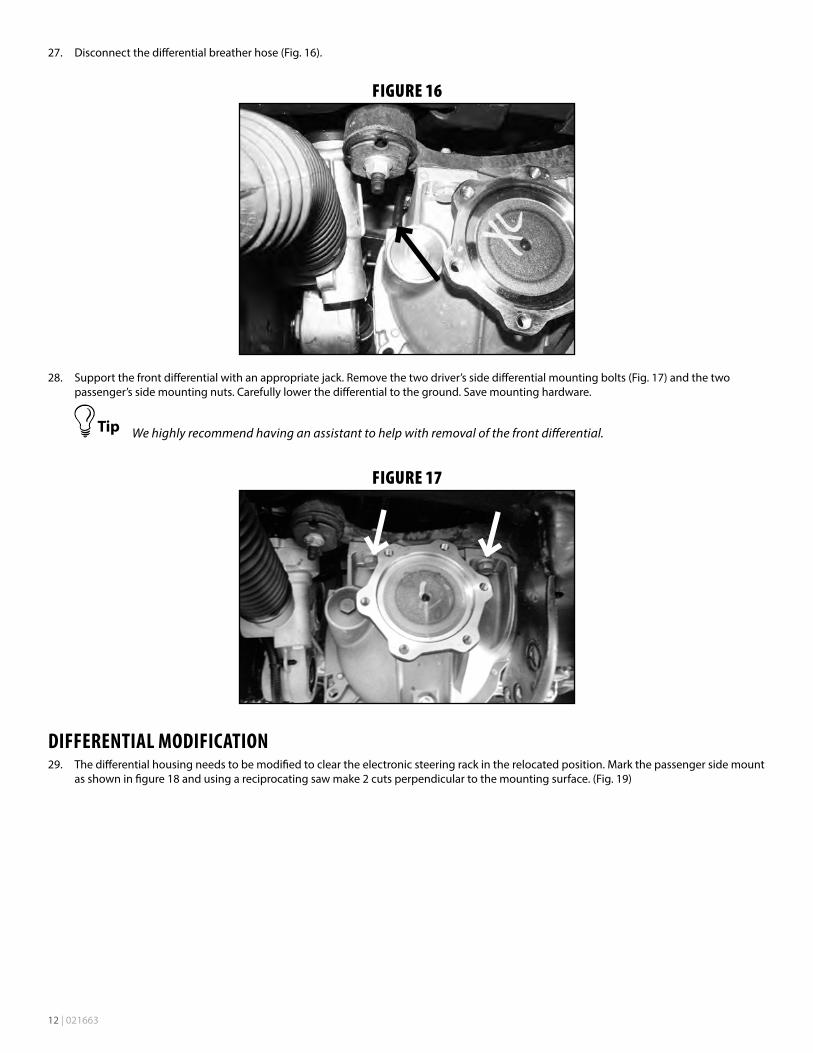
27. Disconnect the differential breather hose (Fig. 16).
FIGURE 16
28. Support the front differential with an appropriate jack. Remove the two driver’s side differential mounting bolts (Fig. 17) and the two passenger’s side mounting nuts. Carefully lower the differential to the ground. Save mounting hardware.
We highly recommend having an assistant to help with removal of the front differential.
FIGURE 17
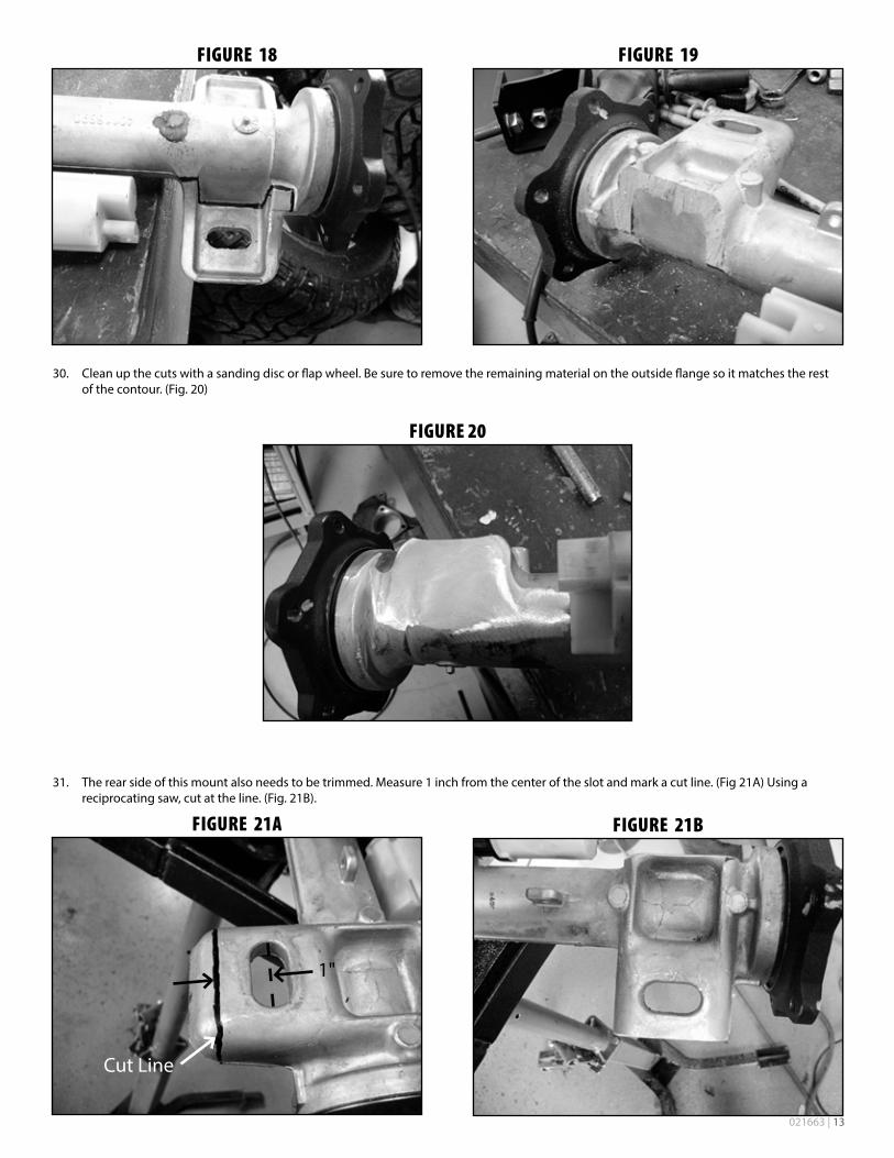
DIFFERENTIAL MODIFICATION29. The differential housing needs to be modified to clear the electronic steering rack in the relocated position. Mark the passenger side mount
as shown in figure 18 and using a reciprocating saw make 2 cuts perpendicular to the mounting surface. (Fig. 19)
021663 | 13
FIGURE 18
FIGURE 19
30. Clean up the cuts with a sanding disc or flap wheel. Be sure to remove the remaining material on the outside flange so it matches the rest of the contour. (Fig. 20)
FIGURE 20
31. The rear side of this mount also needs to be trimmed. Measure 1 inch from the center of the slot and mark a cut line. (Fig 21A) Using a reciprocating saw, cut at the line. (Fig. 21B).
FIGURE 21A
1"
Cut Line
FIGURE 21B
14 | 021663
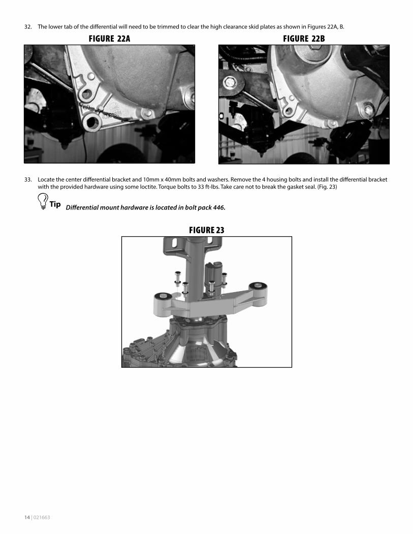
32. The lower tab of the differential will need to be trimmed to clear the high clearance skid plates as shown in Figures 22A, B.
FIGURE 22A
FIGURE 22B
33. Locate the center differential bracket and 10mm x 40mm bolts and washers. Remove the 4 housing bolts and install the differential bracket with the provided hardware using some loctite. Torque bolts to 33 ft-lbs. Take care not to break the gasket seal. (Fig. 23)
Differential mount hardware is located in bolt pack 446.
FIGURE 23

021663 | 15
DIFFERENTIAL INSTALLATION34. Place the provided weld-in plate up against the cut edge of the control arm pocket. The plate should be flush with the bottom edge of the
pocket and overhang the front and back outside surfaces an equal amount. The chamfered corner of the plate should be in the top-front position (Fig. 24). Tack weld the plate in place.
Welding should be performed by an experienced welder. Ensure the battery has been disconnected prior to welding. See pre-installation notes at the beginning of these instructions.
FIGURE 24
35. With the plate tacked, go back and weld the plate in place. Weld along the OUTSIDE of the pocket on the vertical surfaces. Welding on the inside will result in crossmember interference. Weld along the top edge of the plate on the inside of the pocket. Once the area has cooled, paint all exposed metal to prevent corrosion.
36. The rear control arm pocket flanges need to be trimmed for CV shaft clearance. Cut the flange so it is approx. 3/8” from the inside face of the control arm pocket. Verify there is enough clearance once the CV spacers are installed. (Fig. 25, 26)
FIGURE 25 - SHOWN WITH DIFFERENTIAL TO SHOW CLEARANCE
Cut Line
FIGURE 26 - SHOWN WITH DIFFERENTIAL TO SHOW CLEARANCE
Cut Line
37. Install the new driver’s side differential bracket to the original mount with the factory bolts (Fig. 27). The side with the formed end mounts to the OE mount and the open face points toward the inside of the vehicle. Torque bolts to 65 ft-lbs.

16 | 021663
FIGURE 27 - SHOWN WITH DIFFERENTIAL ALREADY INSTALLED
38. Install the new passenger’s side differential bracket to the original mounting studs with the factory nuts (Fig. 28). The bracket is clearanced for the electronic steering rack and mounts with the open face toward the inside of the vehicle. Torque nuts to 65 ft-lbs.
FIGURE 28 - SHOWN WITH DIFFERENTIAL ALREADY INSTALLED
39. Install the differential to the new driver’s and passenger’s differential brackets. Fasten the differential to the driver side bracket with ½” x 1-3/4” bolts, nuts and washers. Use the 5/8” bolt, 5/8” SAE washer and one extra thick 5/8” washer on the passenger’s side. The extra large washer will go against the differential housing flange with the large slots. Leave hardware loose.
Hardware for the differential drop brackets is located in bolt pack 446.
40. Reconnect the differential actuator wiring. Reattach the wire to the differential housing with the factory clips.
41. Reconnect the differential breather line. The line will need to be removed from retaining clips above to gain slack.
The breather line may need to be accessed through the engine compartment to be rerouted for more slack.
42. Reconnect the front drive shaft to the differential as it was removed with the original hardware. Torque bolts to 19 ft-lbs.
43. Install the new rear crossmember with the factory lower control arm bolts, nuts and washers. The tabs on the crossmember should align with the center diff. bracket. Run the bolts from front to rear. Leave hardware loose.
44. Install the front crossmember in the control arm pockets with the factory lower control arm bolts, nuts and washers. When installed, the tabs will align with the center differential mount. Run bolts from front to rear. Leave hardware loose.
45. Install the 9/16” x 4” bolts in the center differential bracket at the front and rear crossmembers. Torque all differential mount hardware: 1/2” hardware to 65 ft-lbs, 9/16” hardware to 90 ft-lbs and the 5/8” hardware to 120 ft-lbs.
021663 | 17
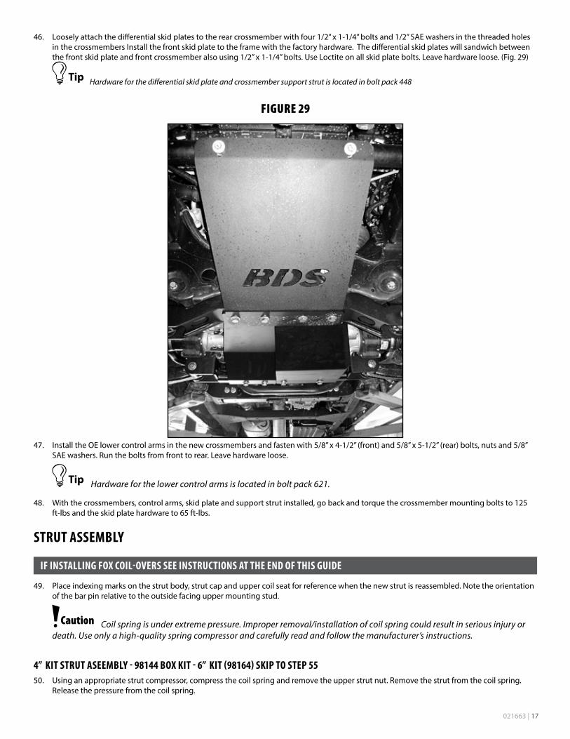
46. Loosely attach the differential skid plates to the rear crossmember with four 1/2” x 1-1/4” bolts and 1/2” SAE washers in the threaded holes in the crossmembers Install the front skid plate to the frame with the factory hardware. The differential skid plates will sandwich between the front skid plate and front crossmember also using 1/2” x 1-1/4” bolts. Use Loctite on all skid plate bolts. Leave hardware loose. (Fig. 29)
Hardware for the differential skid plate and crossmember support strut is located in bolt pack 448
FIGURE 29
47. Install the OE lower control arms in the new crossmembers and fasten with 5/8” x 4-1/2” (front) and 5/8” x 5-1/2” (rear) bolts, nuts and 5/8” SAE washers. Run the bolts from front to rear. Leave hardware loose.
Hardware for the lower control arms is located in bolt pack 621.
48. With the crossmembers, control arms, skid plate and support strut installed, go back and torque the crossmember mounting bolts to 125 ft-lbs and the skid plate hardware to 65 ft-lbs.
STRUT ASSEMBLY
IF INSTALLING FOX COIL-OVERS SEE INSTRUCTIONS AT THE END OF THIS GUIDE
49. Place indexing marks on the strut body, strut cap and upper coil seat for reference when the new strut is reassembled. Note the orientation of the bar pin relative to the outside facing upper mounting stud.
Coil spring is under extreme pressure. Improper removal/installation of coil spring could result in serious injury or death. Use only a high-quality spring compressor and carefully read and follow the manufacturer’s instructions.
4” KIT STRUT ASEEMBLY - 98144 BOX KIT - 6” KIT (98164) SKIP TO STEP 5550. Using an appropriate strut compressor, compress the coil spring and remove the upper strut nut. Remove the strut from the coil spring.
Release the pressure from the coil spring.

18 | 021663
51. Remove the OE jounce bumper from the strut. Remove the jounce bumper cap and slide the OE retaining ring up the strut rod for removal. If necessary, it’s possible to lay the retaining ring across the jaws of a vice and gently tap the end of the strut to get it to slide off.
FIGURE 30
52. Located the provided upper strut cap that has the bump stop cup attached and install the factory jounce bumper into the cup. Install the cap on top of the OE coil seat and shroud. The upper strut cap will only fully seat on the OE coil seat one way. Compress the assembly for strut installation.
53. Remove the new struts from the package and extend the strut by rotating the strut rod counter-clockwise to allow it to extend.
54. Install the new strut, orienting it the same as the factory one, in the coil spring. Fasten the strut with the new provided nut. Pay close attention to the lower mounting bar pin as it is not angled perpendicular to the strut body. This bar pin must be oriented so the bar pin angles down towards the outside of the vehicle once installed. Torque the strut nut to 22 ft-lbs. Do not overtighten the strut stem.
Make sure the coil spring is compressed far enough for the nut to tighten against the cap and is not compressing the coil spring. Improper installation can result in strut stem failure.
FIGURE 31
BDS Strut / Lower Spring SeatStock Coil Spring
Stock Shroud / Upper Spring Seat
BDS Strut Cap
Factory Jounce Bumper
55. Locate the two captive nuts on the OE strut bar pin. Carefully remove these nuts and transfer them to the new strut.
6” KIT STRUT ASSEMBLY - 98165 BOX KIT ONLY
IF INSTALLATING THE 6” 98164 BOX KIT - FOLLOW THE STEPS 50-54.56. Using an appropriate strut compressor, compress the coil spring and remove the upper strut nut. Remove the strut from the coil spring.
Release the pressure from the coil spring and save all of the upper parts for re-installation on the new strut.
57. Remove the OE jounce bumper from the strut. Remove the jounce bumper cap and slide the OE retaining ring up the strut rod for removal. If necessary, it’s possible to lay the retaining ring across the jaws of a vice and gently tap the end of the strut to get it to slide off.

021663 | 19
FIGURE 32A FIGURE 32B
Use provided retaining ring
Stepped Edge Towards Strut Body
58. Install the coil spring isolator from the OE strut on the new one. Install the jounce bumper on the new strut followed by the NEW provided retaining ring with the stepped side towards the strut body. Reinstall the jounce bumper cap to the jounce bumper.
59. Re-install the OE strut cap with the OE coil seat and shroud the same as it was installed on the facotory strut. The upper strut cap fits best on the OE coil seat in one position. It’s easiest to line up your orginal indexing marks from step 49. Compress the assembly for strut installation.
60. Install the new strut, orienting it the same as the factory one, in the coil spring. Fasten the strut with the NEW provided nut. Pay close attention to the lower mounting bar pin as it is not angled perpendicular to the strut body. This bar pin must be oriented so the bar pin angles down towards the outside of the vehicle once installed. Also verify the coil spring is seated properly on the lower spring seat. Torque the strut nut to 22 ft-lbs. Do not overtighten the strut stem.
Make sure the coil spring is compressed far enough for the nut to tighten against the cap and is not compressing the coil spring. Improper installation can result in strut stem failure.
FIGURE 32CBDS Strut / Stock Lower Spring Isolator
Stock Coil Spring
Stock Shroud / Upper Spring Seat
Stock Strut Cap
Jounce Bumper
FRONT ASSEMBLY61. Install the new strut assembly to the appropriate frame mount with the original nuts. Torque the nuts to 40 ft-lbs. Note: Be sure that the
strut is oriented properly in the vehicle.
62. Swing the lower control arm up to the strut and fasten it with the original mounting bolts. Torque lower and upper strut hardware to 40 ft-lbs.
63. Remove the hub bearing/rotor assembly and brake dust shield from the factory steering knuckles. Be sure to note which hub goes on which side of the vehicle. Save mounting bolts.
20 | 021663
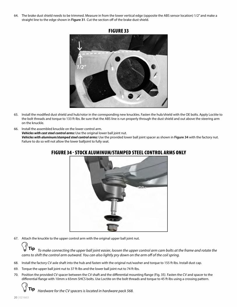
64. The brake dust shield needs to be trimmed. Measure in from the lower vertical edge (opposite the ABS sensor location) 1/2” and make a straight line to the edge shown in Figure 31. Cut the section off of the brake dust shield.
FIGURE 33
1/2"
65. Install the modified dust shield and hub/rotor in the corresponding new knuckles. Fasten the hub/shield with the OE bolts. Apply Loctite to the bolt threads and torque to 133 ft-lbs. Be sure that the ABS line is run properly through the dust shield and out above the steering arm on the knuckle.
66. Install the assembled knuckle on the lower control arm. Vehicles with cast steel control arms: Use the original lower ball joint nut. Vehicles with aluminum/stamped steel control arms: Use the provided lower ball joint spacer as shown in Figure 34 with the factory nut. Failure to do so will not allow the lower balljoint to fully seat.
FIGURE 34 - STOCK ALUMINUM/STAMPED STEEL CONTROL ARMS ONLY
67. Attach the knuckle to the upper control arm with the original upper ball joint nut.
To make connecting the upper ball joint easier, loosen the upper control arm cam bolts at the frame and rotate the cams to shift the control arm outward. You can also lightly pry down on the arm off of the coil spring.
68. Install the factory CV axle shaft into the hub and fasten with the original nut/washer and torque to 155 ft-lbs. Install dust cap.
69. Torque the upper ball joint nut to 37 ft-lbs and the lower ball joint nut to 74 ft-lbs.
70. Position the provided CV spacer between the CV shaft and the differential mounting flange (Fig. 35). Fasten the CV and spacer to the differential flange with 10mm x 65mm SHCS bolts. Use Loctite on the bolt threads and torque to 45 ft-lbs using a crossing pattern.
Hardware for the CV spacers is located in hardware pack 568.

021663 | 21
FIGURE 35
71. Remove the factory tie rod ends and install the new provided tie rod ends. Leave approximately 1/4” of threads showing on the steering link.
72. Remove the front brake line retaining clips and slide the brake line through the bracket. To avoid having to bleed the brakes, cut an opening in the factory brake line bracket so the bracket can be removed from the line. Take care not to nick the brake line. Disconnect the bracket from the frame. Save hardware.
If you are not comfortable with cutting the bracket, disconnect the rubber line from the hard line. The brake system will have to be bled upon completion.
73. Attach the caliper to the new steering knuckle with the original mounting hardware. Torque bolts to 125 ft-lbs.
74. Carefully remove the metal retainer bracket from the factory rubber brake line. This can be done with two vice grips, pliers, or crescent wrenches.
It may be easier to remove the brake line from the bracket by removing it from the vehicle completely and holding the bracket in a bench vise. If the brake line is removed, the system will need to be bled.
75. Align the tab in the provided brake line bracket to the upper control arm mount and attach the bracket using the original mounting hole and OE bolt (Fig. 36) Torque the brake line bracket to 20 ft-lbs.
FIGURE 36
76. Carefully reform the brake hard line down so it meets the new bracket. Run the end of the rubber brake hose through the bracket and retain the brake line to the bracket with the original clip.
22 | 021663
77. Attach the ABS line to the upper control arm with the original brake line mounting bolt and provided wire clamp. (Fig. 37)
FIGURE 37
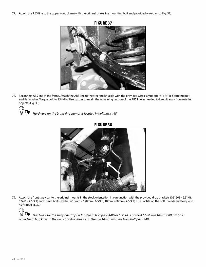
78. Reconnect ABS line at the frame. Attach the ABS line to the steering knuckle with the provided wire clamps and ¼” x ¾” self tapping bolt and flat washer. Torque bolt to 15 ft-lbs. Use zip ties to retain the remaining section of the ABS line as needed to keep it away from rotating objects. (Fig. 38)
Hardware for the brake line clamps is located in bolt pack 448.
FIGURE 38
79. Attach the front sway bar to the original mounts in the stock orientation in conjunction with the provided drop brackets (02166B - 6.5” kit, 02491 - 4.5” kit) and 10mm bolts/washers (10mm x 120mm - 6.5” kit, 10mm x 80mm - 4.5” kit). Use Loctite on the bolt threads and torque to 45 ft-lbs. (Fig. 39)
Hardware for the sway bar drops is located in bolt pack 449 for 6.5” kit. For the 4.5” kit, use 10mm x 80mm bolts provided in bag kit with the sway bar drop brackets. Use the 10mm washers from bolt pack 449.
021663 | 23
FIGURE 39
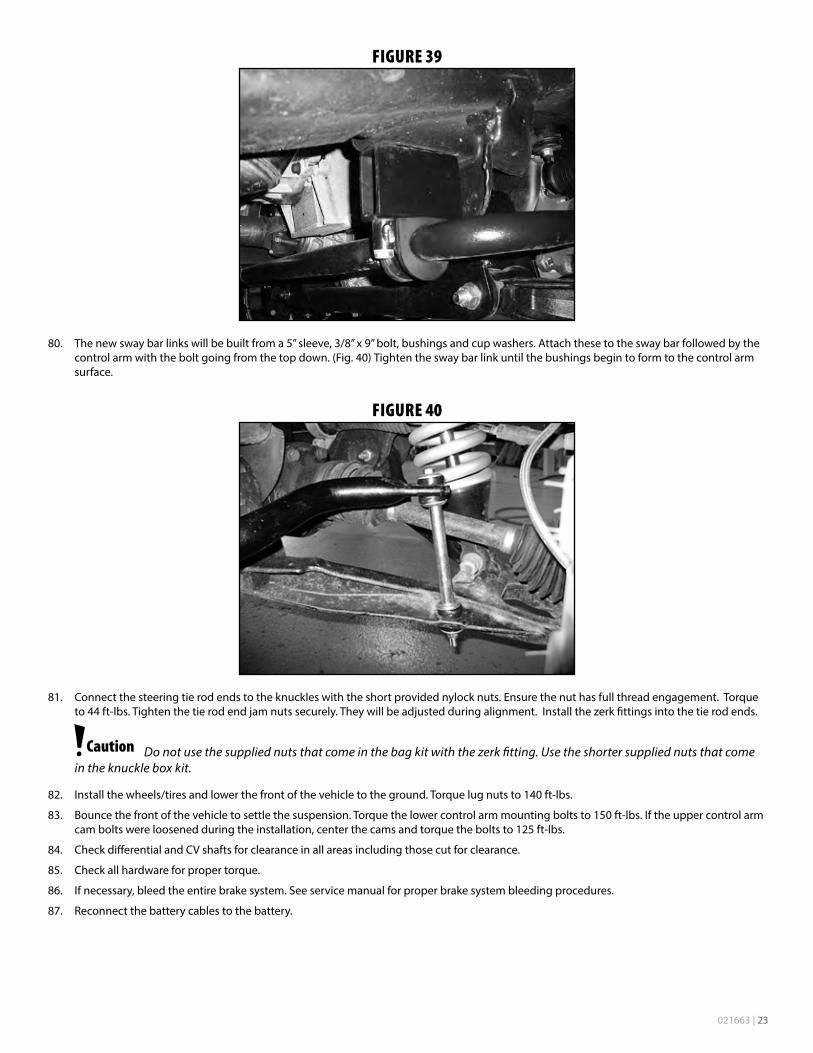
80. The new sway bar links will be built from a 5” sleeve, 3/8” x 9” bolt, bushings and cup washers. Attach these to the sway bar followed by the control arm with the bolt going from the top down. (Fig. 40) Tighten the sway bar link until the bushings begin to form to the control arm surface.
FIGURE 40
81. Connect the steering tie rod ends to the knuckles with the short provided nylock nuts. Ensure the nut has full thread engagement. Torque to 44 ft-lbs. Tighten the tie rod end jam nuts securely. They will be adjusted during alignment. Install the zerk fittings into the tie rod ends.
Do not use the supplied nuts that come in the bag kit with the zerk fitting. Use the shorter supplied nuts that come in the knuckle box kit.
82. Install the wheels/tires and lower the front of the vehicle to the ground. Torque lug nuts to 140 ft-lbs.
83. Bounce the front of the vehicle to settle the suspension. Torque the lower control arm mounting bolts to 150 ft-lbs. If the upper control arm cam bolts were loosened during the installation, center the cams and torque the bolts to 125 ft-lbs.
84. Check differential and CV shafts for clearance in all areas including those cut for clearance.
85. Check all hardware for proper torque.
86. If necessary, bleed the entire brake system. See service manual for proper brake system bleeding procedures.
87. Reconnect the battery cables to the battery.
24 | 021663
REAR INSTALLATION1. Block the front wheels. Safely raise the rear of the vehicle and support with jack stands just ahead of the front leaf spring frame mount.
2. Remove the wheels.
3. Support the rear axle with a floor jack.
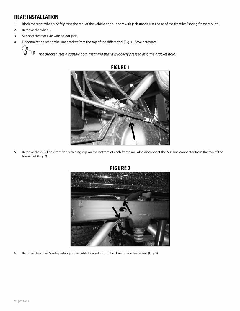
4. Disconnect the rear brake line bracket from the top of the differential (Fig. 1). Save hardware.
The bracket uses a captive bolt, meaning that it is loosely pressed into the bracket hole.
FIGURE 1
5. Remove the ABS lines from the retaining clip on the bottom of each frame rail. Also disconnect the ABS line connector from the top of the frame rail. (Fig. 2).
FIGURE 2
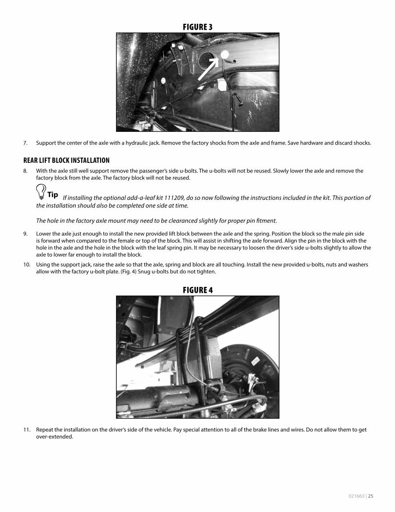
6. Remove the driver’s side parking brake cable brackets from the driver’s side frame rail. (Fig. 3)
021663 | 25
FIGURE 3
7. Support the center of the axle with a hydraulic jack. Remove the factory shocks from the axle and frame. Save hardware and discard shocks.
REAR LIFT BLOCK INSTALLATION8. With the axle still well support remove the passenger’s side u-bolts. The u-bolts will not be reused. Slowly lower the axle and remove the
factory block from the axle. The factory block will not be reused.
If installing the optional add-a-leaf kit 111209, do so now following the instructions included in the kit. This portion of the installation should also be completed one side at time.
The hole in the factory axle mount may need to be clearanced slightly for proper pin fitment.
9. Lower the axle just enough to install the new provided lift block between the axle and the spring. Position the block so the male pin side is forward when compared to the female or top of the block. This will assist in shifting the axle forward. Align the pin in the block with the hole in the axle and the hole in the block with the leaf spring pin. It may be necessary to loosen the driver’s side u-bolts slightly to allow the axle to lower far enough to install the block.
10. Using the support jack, raise the axle so that the axle, spring and block are all touching. Install the new provided u-bolts, nuts and washers allow with the factory u-bolt plate. (Fig. 4) Snug u-bolts but do not tighten.
FIGURE 4
11. Repeat the installation on the driver’s side of the vehicle. Pay special attention to all of the brake lines and wires. Do not allow them to get over-extended.
26 | 021663
REAR LEAF SPRING INSTALLATION12. With the rear axle supported, remove the passenger side leaf spring u-bolts. Discard the u-bolts, nuts and washers.
13. Lower the axle from the leaf spring. For 6” kits, leave the OE block on the axle, it will be re-used with the new spring. For 4” kits remove the OE block, it will not be reused.
14. Loosen both the shackle to frame and shackle to spring bolts. Remove the nut from the bolt mounting the spring to the shackle. Next remove the front spring hanger bolt far enough to remove the spring from the mount. The exhaust may need to be pushed over temporarily for bolt removal.
15. Remove the spring by pulling the spring out of the front hanger and swinging the shackle forward so the shackle bolt can be removed through a hole in the hitch.
16. Lightly grease and install the provided bushings (3521BK) and sleeve (30) at front (short side) of the spring. Install the smaller ID sleeve (49) at the shackle end.
17. Install the new spring in the vehicle with the OE hardware. Be sure the shim on the bottom of the leaf pack tapers down as it goes toward the front of the vehicle. Leave hardware loose.
18. Raise the rear axle while aligning the center pin in the leaf spring with the center pin hole in the OE block. Install two new u-bolts over the spring pack, block (6” kits only), and axle tube. From the underside of the axle tube, place the OE lower u-bolt plate over the u-bolts and hold the assembly together with the 9/16” high nuts and washers. Snug u-bolts. Final u-bolt torque is done with the weight of the vehicle on the springs.
19. On the driver side the fuel tank will need to be moved to provide clearance to the front spring hanger bolt. First remove the 3 bolts mounting the fuel tank skid to the frame rail. Remove the skid by releasing the clips on the inside of the skid.
20. Support the gas tank with two jacks, one towards the front and one towards the rear. As a precaution, disconnect the two fittings at the front of the tank so no damage to the lines or fittings occurs once the tank is moved.
A slight amount of gas will drain from the lines once disconnected.
21. With the tank well supported, remove the two gas tank straps and lower the gas tank far enough to clear the inside tank strap frame mounts. This will allow enough clearance to slide the tank over and remove the bolt.
22. With the tank moved, follow a similar procedure to remove and install the spring as done on the passenger side. Before re-mounting the fuel tank, torque the front driver side spring hanger bolt to 125 ft-lbs.
REAR INSTALLATION CONTINUED - ALL KITS
Hardware for the bump stop spacers is located in hardware pack #628.
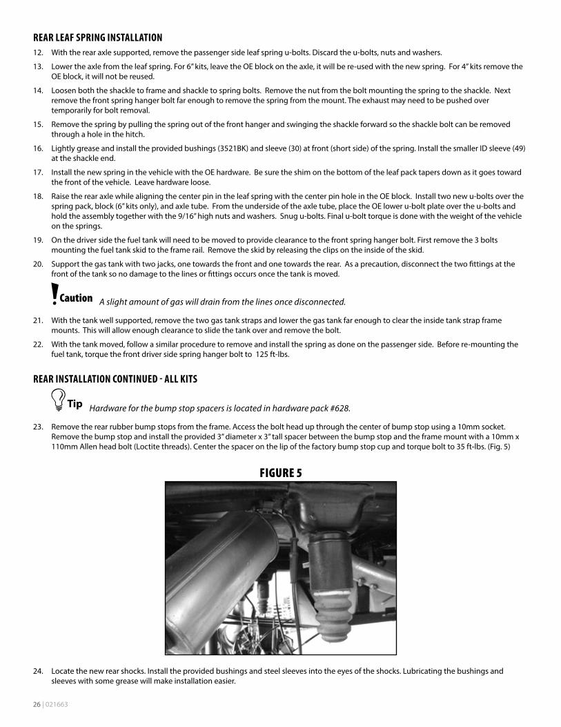
23. Remove the rear rubber bump stops from the frame. Access the bolt head up through the center of bump stop using a 10mm socket. Remove the bump stop and install the provided 3” diameter x 3” tall spacer between the bump stop and the frame mount with a 10mm x 110mm Allen head bolt (Loctite threads). Center the spacer on the lip of the factory bump stop cup and torque bolt to 35 ft-lbs. (Fig. 5)
FIGURE 5
24. Locate the new rear shocks. Install the provided bushings and steel sleeves into the eyes of the shocks. Lubricating the bushings and sleeves with some grease will make installation easier.

021663 | 27
25. Install the new shocks with stock hardware and torque upper and lower bolts to 65 ft-lbs. The axle mounting tabs may need to be bent open slightly to allow for clearance of the larger diameter shocks.
Hardware for the brake line bracket is located in hardware pack #628.
26. Install the provided straight 3” brake line bracket to the top of the differential using factory mounting hole and bolt which must be removed from the factory brake line bracket. Attach the factory brake line bracket to the relocation bracket with a 5/16” x 1” bolt, nut and washers. Torque the factory and 5/16” bolt to 20 ft-lbs. (Fig. 6)
Be sure the ABS wire will not contact the exhaust.
FIGURE 6
27. Reconnect the ABS lines to the plastic retaining clip at the bottom of each frame rail. The connector will not be reattached to the top of the frame. Reroute the lines as necessary to gain proper slack.
28. Reconnect the parking brake cable brackets to the driver’s side frame rail with the original hardware. The driver’s side cable will have to be removed from the rear bracket to gain appropriate slack. Torque bolts to 20 ft-lbs.
29. Install wheels and tires. Torque lug nuts to 140 ft-lbs. Lower vehicle.
30. Bounce the rear of the vehicle to settle the suspension. Torque leaf spring u-bolts to 100-120 ft-lbs. If new springs were installed, torque the spring-to-shackle and shackle-to-frame bolts to 70 ft-lbs. Torque the front spring hanger bolts to 125 ft-lbs.
POST INSTALLATION31. Double check all fasteners for proper torque.
32. Check all moving parts for clearance.
33. Complete a full radius turning check to ensure that no interference occurs.
34. Align headlights
35. Double check the brake lines for adequate slack at full wheel travel.
36. Complete a vehicle alignment.
37. Check all fasteners after 500 miles.
28 | 021663
FOX COIL-OVER INSTALLATION ADDENDUM1. The coil-overs are installed with the reservoir hose at the rear of the vehicle. Determine the appropriate coil-over for each side.
2. Loosely attach the coil-over to the upper mount using the two inner most upper mounting bolts with washers.
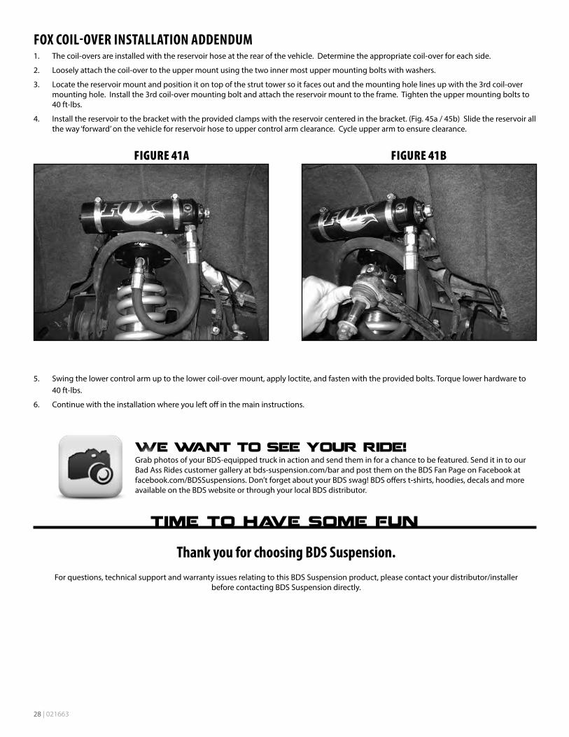
3. Locate the reservoir mount and position it on top of the strut tower so it faces out and the mounting hole lines up with the 3rd coil-over mounting hole. Install the 3rd coil-over mounting bolt and attach the reservoir mount to the frame. Tighten the upper mounting bolts to 40 ft-lbs.
4. Install the reservoir to the bracket with the provided clamps with the reservoir centered in the bracket. (Fig. 45a / 45b) Slide the reservoir all the way ‘forward’ on the vehicle for reservoir hose to upper control arm clearance. Cycle upper arm to ensure clearance.
FIGURE 41A FIGURE 41B
5. Swing the lower control arm up to the lower coil-over mount, apply loctite, and fasten with the provided bolts. Torque lower hardware to 40 ft-lbs.
6. Continue with the installation where you left off in the main instructions.
Thank you for choosing BDS Suspension.For questions, technical support and warranty issues relating to this BDS Suspension product, please contact your distributor/installer
before contacting BDS Suspension directly.