Embed Size (px)
Citation preview
3D Virtual Clothing: from Garment Design
to Web3D Visualization and Simulation
Luca Chittaro
HCI Lab, Dept. of Math and Computer Science University of Udine
via delle Scienze 206, 33100 Udine, Italy +39 0432 558450
Demis Corvaglia
HCI Lab, Dept. of Math and Computer Science University of Udine
via delle Scienze 206, 33100 Udine, Italy
ABSTRACT One of the major challenges in Computer Graphics concerns the
3D representation and physically-based simulation of garments. In
our research, we are working closely with the textile industry,
investigating three different classes of problems. First, we aim at
developing techniques and methods for cloth simulation
specifically aimed at the Web3D context. Second, we are defining
a cross-application data exchange format among the different
CAD systems and applications used in the textile industry,
including the additional information needed to support 3D
simulations. Third, we are implementing a tool that complements
traditional textile CAD systems (which are based on 2D graphics),
allowing the user to automatically obtain VRML-based 3D
previews of the garment (for evaluating garment designs and also
easily publishing them on the Web). This paper illustrates the
results we have achieved in these three directions.
Categories and Subject DescriptorsI.3.5 [Computer Graphics]: Computational Geometry and Object
Modeling – Physically based modeling. I.3.6 [Computer
Graphics]: Methodology and Techniques – Interaction
techniques and standards. I.3.7 [Computer Graphics]: Three-
Dimensional Graphics and Realism – Animation, and virtual
reality. H.5.1[Information Interfaces and Presentation]:
Multimedia Information Systems – Artificial, augmented, and
virtual realities. J.6 [Computer-Aided Engineering]: Computer-
aided design (CAD).
General TermsAlgorithms, Performance, Design, Standardization.
KeywordsPhysically-based simulation, virtual clothing, cross-application
data exchange format for the textile industry, CAD tools for
garment design, Product Visualization, VRML/Java, XML.
1. INTRODUCTION Physically-based computer animation is one of the relevant
research areas in Computer Graphics [17]. One of the several
challenges in this area concerns the 3D representation and
simulation of garments. This is crucial for industries as different
as the movie industry (that needs to include very realistic
animated characters in its productions) and the fashion and textile
industry, whose purpose is twofold: on one side, they would like
to build virtual prototypes of garments for evaluating a design
without the need for actually producing it; on the other side, they
would like to develop virtual try-on applications allowing
consumers to see how a garment fits on their individual body
measures.
An ideal 3D garment simulation should be both very efficient
(e.g., real-time animation) and high-fidelity (e.g., deformations of
cloth caused by the shape of a specific human body, different
behaviors determined by the materials of which the garment is
made). Unfortunately, the high computational complexity of the
simulation makes it very difficult to achieve both goals: existing
systems are tailored to favor one of the two. Systems that are
capable of real-time animation can produce impressive results, but
are of scarce interest to the textile industry, because the obtained
results are not reliable and cannot be used to predict how the
actual garment will look and behave in the physical world. High-
fidelity simulation of a garment might require hours of
computation to produce a few seconds of animation. However,
while its results are highly realistic and satisfactory from the point
of view of the movie industry, it still presents open issues (e.g.,
integration with existing textile design tools) from the point of
view of the fashion designer. In our research, we are working
closely with the textile industry (in particular, with the Benetton
Group), investigating three different classes of problems.
First, we are developing techniques for cloth simulation aimed at
building a garment simulation engine for the Web3D context.
Second, we are defining a cross-application data exchange format
aimed at allowing data interchange among the different CAD
systems and applications used in the textile industry, including the
additional information needed to support 3D simulations.
Third, we are implementing a tool that complements traditional
textile CAD systems (which are based on 2D graphics), allowing
the user to automatically obtain VRML-based 3D previews of the
garment (for evaluating garment designs and also easily
publishing them on the Web). The tool is based on the previously
mentioned simulation engine and interchange format.
This paper illustrates the results we have achieved in the three
directions.
2. THE TEXTILE INDUSTRY CONTEXT In this section, we briefly illustrate the typical design and
production chain followed in the textile industry, to better
motivate the need for 3D virtual prototyping systems.
Garment production starts from garment conception and design.
For many new concepts of garment, tailors must be involved in
the design process to produce actual prototypes for evaluation and
market research purposes. Results of market research can lead to
discarding the design or changing it (in the latter case, another
prototype needs to be produced and evaluated). This is a very
expensive iterative process for the industry: for any accepted
design, many more are discarded and will not go into production.
Since the production process is based on cutting and stitching
together parts of cloth, traditional textile CAD systems are aimed
at drawing these 2D parts and driving automatic cutting
procedures (e.g., Gerber Technology [11], Investronica Sistemas
[13]). Procedures for stitching parts (and accessories such as
buttons, zips,...) are not handled by the CAD system and require
human operators to program the stitching machines.
To improve the efficiency of the garment conception and design
phase, a proposed solution is to adopt virtual prototyping
techniques. Exploiting 3D virtual garment models would allow
the industry to dramatically reduce both the time before going to
market and the work costs. Moreover, virtual prototypes can be
reused for an additional purpose, i.e. 3D product visualization on
the Web.
It must be noted that 3D virtual prototyping requires to extend
existing CAD systems (or propose tools that complement them) to
handle additional information (e.g., stitching data) needed to
define the 3D model and to provide high fidelity simulation of the
garment. Unfortunately, no solutions have been yet proposed for
these problems in the textile industry.
In our research, we are pursuing both goals to propose an
integrated system. In particular, we aim at defining a flexible
simulation engine that allows the user to choose the desired
tradeoff between performance and fidelity. For example, given a
short computation time, one could choose between an high fidelity
garment simulation in a static mannequin positions or an high
performance garment simulation on animated mannequins.
3. A QUICK INTRODUCTION TO GARMENT
SIMULATION Garment simulation and visualization is a complex task that can
be subdivided in four main subtasks:
• Geometrical definition of garment parts and of objects that
will interact with the garment (e.g, a specific human body);
• Optical laws simulation (rendering);
• Dynamic laws simulation (forces, accelerations, velocities,
energies);
• Interaction with the environment (collision detection and
response). Garment simulation is mainly concentrated on the
interaction between the different parts of the garment and the
virtual body (mannequin).
While, the first two issues are classic 3D graphics problems, the
last two require to face the following problems:
• Cloth behaviour simulation: cloth simulation concerns the
mechanical model adopted for garment parts behaviour
approximation. It can be a parametric model to allow different
material simulation (e.g., cotton, wool, silk,...).
• Handling of constrictions: constrictions concern limitations of
garment movement such as those caused by the seams
between parts of a garment or by placing the garment on a
coat hanger.
• Collision detection: Collisions must be detected between the
garment and the human body as well as garment parts
themselves (self-collisions).
• Physically-based response: Every collision needs a response
to avoid interpenetration and simulate friction and bouncing
effects.
Initial work on the simulation of garments [10] concentrated only
on the geometrical features of deforming cloth, while the first
physically-based models were proposed in the early ‘90s [6] [20].
Different physically-based approaches have been proposed, e.g.
some exploit particles systems for mechanical simulation [5][8]
while others employ continuous models resolved by finite
elements [9]. Although finite elements have shown the greatest
accuracy (at high computational costs), particles systems became
the preferred approach in the computer graphics community for
their simplicity, flexibility and their fidelity/performance ratio.
In general, computational costs are mainly due to numerical
integration of the ODE (Ordinary Differential Equation) systems
that model the cloth, and to collision detection needs. From the
point of view of numerical integration, existing approaches might
use either explicit or implicit methods. Classic explicit integration
methods such as Euler, Midpoint, or Runge-Kutta are relatively
easy to implement, but need very small integration steps to
guarantee system stability. Implicit methods (e.g., the implicit
versions of the three classic methods mentioned above) are able to
use larger steps without loss of stability, but are more complex to
implement because they need to solve large linear systems at
every integration step. The use of implicit methods in cloth
simulation was first proposed by [2].
From the point of view of collision detection, heuristics are
typically used to limit the number of collision tests to be
performed. In particular, the most used heuristics are space
subdivision (e.g., voxel, octree, bounding-box) and hierarchical
orders. A specific problem of cloth simulation is the need of
managing self-collisions. To this purpose, good results have been
achieved in [21] where the global surface is partitioned in smaller
parts whose dimension is inversely proportional to the curvature
of the parts themselves. This subdivision allows one to avoid
performing self-collision tests on those parts that do not reach the
needed curvature.
4. A JAVA/VRML CLOTH SIMULATOR As we have previously seen, garment simulation is a complex task
both from a conceptual and computational point of view.
Research in this field often exploits very fast and expensive
graphics workstations and proprietary environments. In our work,
we are interested in exploiting conventional hardware and
platform-independent software to be used also on the Web.
In this Section, we propose a cloth simulation engine based on
VRML and Java. First, we illustrate the modelling and
algorithmic choices we made; then, we discuss how they were
implemented in VRML/Java.
4.1 Simulation method One of the main tradeoffs in cloth simulation is the one between
fidelity and performance. Considering the intended context of use
for our simulator, we offer some variable settings by which the
user can choose to trade some performance in favor of more
fidelity or vice versa. A generic physically-based simulator runs in
a loop, containing the following four main activities [17]:
• Force computation: there are a lot of forces to be managing
for reproduce real world phenomena. Gravity for example is a
most important one, but other forces such as air viscosity and
wind improve the simulation fidelity. More kinds of force we
consider, more results are similar to real world ones.
• Collision detection: graphical objects are defined
geometrically and located in a 3D virtual environment; when
two objects reach a contact point (or a interpenetration) the
collision detection algorithm musts to recognise it and notify
the details to collision response task.
• Collision response: the collision between two objects
produces forces that modify positions and velocities according
with conservation laws when collision is elastic, otherwise
with energy dispersion.
• State integration: simulator works by discrete time steps.
When forces are computed these produces acceleration on
objects. During time step this acceleration is considered
constant and so we can use cinematic laws or advanced
integration techniques for compute new object positions.
For animation purposes, we need to know particles position at
close time instants (e.g., the temporal distance between one
position and the following one should be 33ms to obtain a 30fps
animation). However, stable state integration often requires
smaller integration steps.
4.1.1 The Adopted Mechanical model and Super-elasticity
Issues For cloth modeling purposes, we adopt a particle system approach
based on a mass-spring model. In the literature, the mass-spring
model is widely used to simulate any elastic body. A typical good
topology for a mass-spring model aimed at cloth simulation is
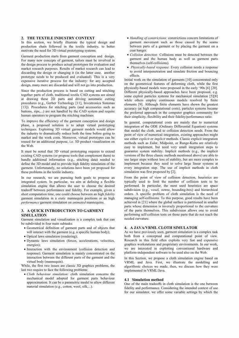
illustrated in Figure 1. The nodes represent mass elements, the
arcs between nodes represent spring elements, and the modeler
can define several parameters such as particle mass value; elastic
constants for traction (in weft and warp direction), bending (in
weft and warp direction), shearing; constants for damping, friction
and bouncing.
By using different settings for the parameters, it is possible to
simulate different kinds of cloth. For example, Figure 6 shows the
simulation of two different cloths (the right one is lighter and
more elastic than the left one).
A well known problem of mass-spring models is the super-
elasticity effect, i.e. small elastic constant produce unrealistic
cloth behaviour (due to excessive spring extension). A simple way
to minimize this undesired effect is to decrease elasticity settings,
but, as a result, the ODE system that models the mass-spring
topology can become stiff, and lead to instability.
There are both numerical and empirical solutions to the super-
elasticity problem. Numerical solutions are based on implicit
integration, but its implementation is complex as already
mentioned in Section 3. Empirical solutions for explicit methods
have been proposed by [16] [19] and are based on limiting the
extension of the spring. More specifically, Provot [16]
manipulates directly the position of particles when the extension
becomes excessive, and then applies an inverse dynamics
procedure for the global distribution of modifications (this
procedure ends up adding computation time). The approach by
Vassilev [19] temporarily sets to zero the extension velocity of
those particles that are showing super-elasticity effects to prevent
further extensions (note that, in explicit integration methods, the
position of a particle at time t+1 is given by its position at time t
plus its velocity multiplied by the integration step).
Unfortunately, this solution produces discontinuous (unrealistic)
behaviours.
Figure 1. Mass-spring topology: a) global structure;
b) vertical and horizontal springs; c) shearing springs;
d) bending springs.
However, the super-elasticity effect tends to affect meshes whose
resolution (i.e., the number of mass and spring elements for
unitary area) is high. Therefore, our system adopts the following
approach. If the user requires a fast simulation by setting a low
resolution for the mesh, we do not take actions to prevent super-
elasticity effects (because they are minimal), and we instead
concentrate on reducing anti-aesthetic effects (due to the large
area of polygons in a low-resolution mesh). To do so in a simple
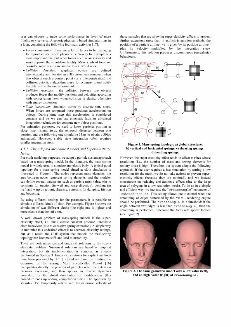
and efficient way, we increase the “creaseAngle” parameter of
IndexedFaceSet. This setting allows one to control when the
smoothing of edges performed by the VRML rendering engine
should be performed. The creaseAngle is a threshold: if the
angle between two edges is less than creaseAngle, then the
smoothing is performed, otherwise the faces will appear faceted
(see Figure 2).
Figure 2. The same geometric model with a low value (left),
and an high value (right) of creaseAngle .
If the user trades efficiency in favor of more fidelity by increasing
the resolution of the mesh, the system offers the possibility of
increasing rigidity settings (to minimize super-elasticity effects)
and decreasing the size of the integration step (to prevent
instability).
4.1.2 Forces Time evolution of particle system is determined by resultant
forces exerted on each particle. Some forces originate from
internal factors in the mechanical model of the cloth, other are
due to external environmental factors such as gravity, viscosity,
wind, constriction and collision. We consider all these
contributions and compute the resulting force for each particle by
using the following equations:
( )l
l
l
ll'lf
vf
gf
e
v
g
⎥⎥⎦
⎤
⎢⎢⎣
⎡ ⋅+−−=
=
=
de
v
krk
-k
m
where m is the particle mass, g the gravitational constant, fg the
gravitational force, v is the particle velocity, kv is the fluid (e.g.,
air, water) viscosity constant, fv is the viscosity force, l is the
spring length (between two particles), l’ is the elongation
velocity, r is the rest position of the spring, ke is the elastic
constant of the spring (Young module), kd the damping constant
of the spring, fe is the elastic force exerted on the particle linked
to the spring (- fe in the case of the particle linked to the other
side).
Wind forces are proportional to scalar product between wind
direction and the normal of each face of the cloth.
4.1.3 Collision detection and response The algorithms we currently use compute collisions by using
geometric data from IndexedFaceSet VRML nodes.
Geometrical detection of collisions is simply performed from each
particle of the cloth and each face of the colliding object. We are
working to improve this naive method using space subdivision
techniques. Collision response modifies forces and velocities as
described in [15]. This technique allows us to control friction and
bouncing effects.
4.1.4 Numerical integration Given the resulting force that acts on a particle we can compute
its new position in 3D space using Newton’s first law and classic
cinematic laws.
More specifically, from equation f = ma (where f is the
resultant force vector acting on the particle, and m its mass value),
we obtain a (the acceleration vector).
Considering the one-dimensional case, continuous cinematic law
at constant acceleration x = d2a/dt
2determines the position of the
particle at time t. Introducing velocity, one obtains two
differential equations: v = da/dt and x = dv/dt. The state of a
particle at time t is completely determined by position and
velocity values. In the 3D case, we represent this by the vector
[x1 x2 x3 v1 v2 v3], a generic element of a six-dimensional phase
space. This notation allow us to write the differential operator as
follows:
x = [x1 x2 x3 v1 v2 v3]
x’ = [x’1 x’2 x’3 v’1 v’2 v’3] = [v1 v2 v3 f1/m f2/m f3/m]
Suppose that force f = [f1 f2 f3] depends only on x and t, we
can write the ODE:
x’ = F(x, t)
Starting from an initial value x0 = x(t0), we can solve the ODE
with several integration methods. Our simulation engine
implements three explicit methods: Euler, Midpoint, and fourth-
order Runge-Kutta.
The simplest method (Euler) produces an approximation value as
follows:
x(t0 + h) = x0 + hx’(t0)
where h is the integration step.
This method is formally justified by Taylor’s series:
x(t0 + h) = x0 + hx’(t0) + (h2/2!)x’’(t0) + (h3/3!)x’’’(t0) +
…+ (hn/n!)(∂ nx/∂ tn)+ …
where one can easily notice that the Euler method is based on
deleting the parts of the series that contain higher order
derivatives. Accuracy of approximation is determined by the
temporal extent of the integration step and the size of the values
of the higher order derivatives that have been ignored by the
method.
Midpoint methods uses instead the following equation:
x(t0 + h) = x0 + h(f(x0 + (h/2)f(x0))
Finally, these are the equations of fourth-order Runge-Kutta:
k1 = hf(x0, t0 )
k2 = hf(x0 + k1/2, t0 + h/2)
k3 = hf(x0 + k2/2, t0 + h/2)
k4 = hf(x0 + k3, t0 + h)
x(t0 + h) = x0 + (1/6) k1 + (1/3) k2 + (1/3) k3 + (1/6) k4
For the mathematical justification of these methods, we refer the
reader to numerical analysis textbooks (e.g. [3][7]).
The use of implicit methods has not been considered to avoid
increasing the complexity of the simulator.
4.2 Simulating cloth parts and garments The simulation method described in the previous section has been
implemented with a Java class. We now introduce the three main
VRML nodes (SimulationScript, Garment and ObjectCollider
PROTOs) that allow one to invoke the simulation method inside
the 3D world. The physics simulation obtainable with these nodes
considers gravity, viscosity, wind and collision detection between
a textile part and a user-defined object (it will be typically a
mannequin, but it can also be any other object, e.g., a chair or
table). The structure of the SimulationScript node is the
following:
1 DEF SimulationScript Script2 { 3 mustEvaluate TRUE 4 eventIn SFTime DefineClothGeometry 5 eventIn SFTime ComputeNewFrame 6 7 field SFNode garment USE UserDefinedGarment 8 field SFNode collider USE UserDefinedObject 910 field SFFloat viscosity_const 0.2
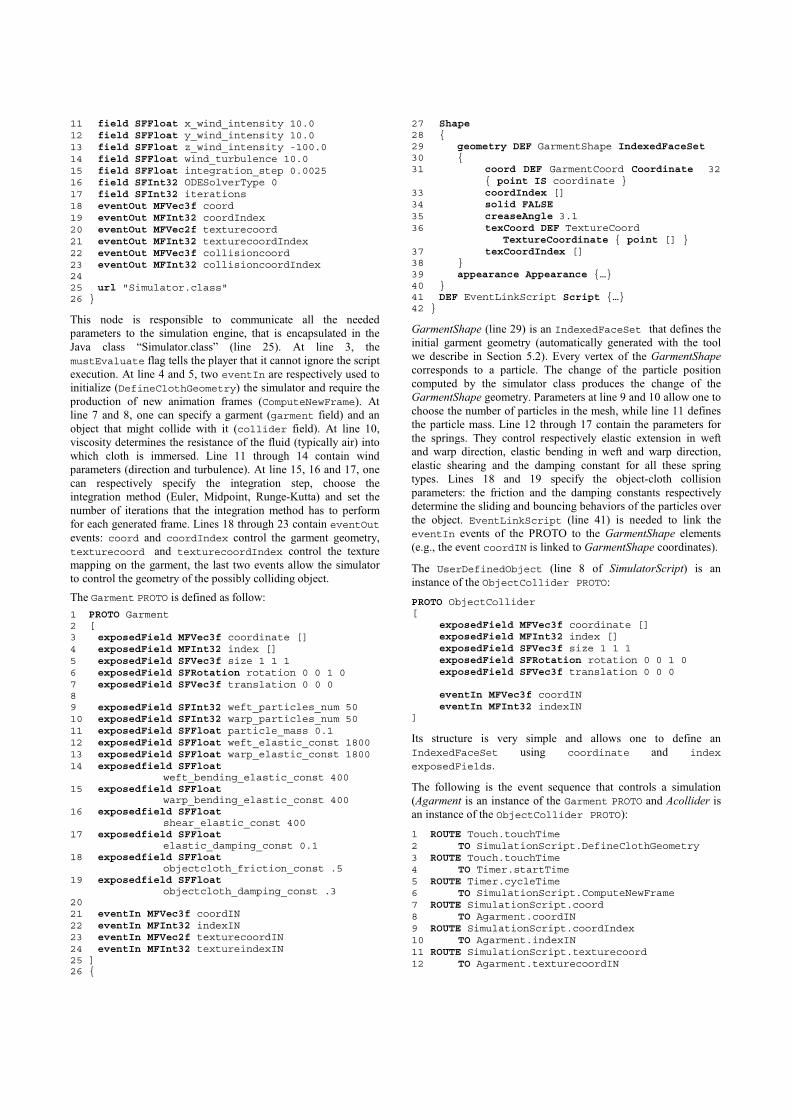
11 field SFFloat x_wind_intensity 10.0 12 field SFFloat y_wind_intensity 10.0 13 field SFFloat z_wind_intensity -100.0 14 field SFFloat wind_turbulence 10.0 15 field SFFloat integration_step 0.0025 16 field SFInt32 ODESolverType 0 17 field SFInt32 iterations 18 eventOut MFVec3f coord 19 eventOut MFInt32 coordIndex 20 eventOut MFVec2f texturecoord 21 eventOut MFInt32 texturecoordIndex 22 eventOut MFVec3f collisioncoord 23 eventOut MFInt32 collisioncoordIndex 24 25 url "Simulator.class" 26 }
This node is responsible to communicate all the needed
parameters to the simulation engine, that is encapsulated in the
Java class “Simulator.class” (line 25). At line 3, the
mustEvaluate flag tells the player that it cannot ignore the script
execution. At line 4 and 5, two eventIn are respectively used to
initialize (DefineClothGeometry) the simulator and require the
production of new animation frames (ComputeNewFrame). At
line 7 and 8, one can specify a garment (garment field) and an
object that might collide with it (collider field). At line 10,
viscosity determines the resistance of the fluid (typically air) into
which cloth is immersed. Line 11 through 14 contain wind
parameters (direction and turbulence). At line 15, 16 and 17, one
can respectively specify the integration step, choose the
integration method (Euler, Midpoint, Runge-Kutta) and set the
number of iterations that the integration method has to perform
for each generated frame. Lines 18 through 23 contain eventOutevents: coord and coordIndex control the garment geometry,
texturecoord and texturecoordIndex control the texture
mapping on the garment, the last two events allow the simulator
to control the geometry of the possibly colliding object.
The Garment PROTO is defined as follow:
1 PROTO Garment 2 [ 3 exposedField MFVec3f coordinate [] 4 exposedField MFInt32 index [] 5 exposedField SFVec3f size 1 1 1 6 exposedField SFRotation rotation 0 0 1 0 7 exposedField SFVec3f translation 0 0 0 89 exposedField SFInt32 weft_particles_num 50 10 exposedField SFInt32 warp_particles_num 50 11 exposedField SFFloat particle_mass 0.1 12 exposedField SFFloat weft_elastic_const 1800 13 exposedField SFFloat warp_elastic_const 1800 14 exposedfield SFFloat weft_bending_elastic_const 400 15 exposedfield SFFloat warp_bending_elastic_const 400 16 exposedfield SFFloat shear_elastic_const 400 17 exposedfield SFFloat elastic_damping_const 0.1 18 exposedfield SFFloat objectcloth_friction_const .5 19 exposedfield SFFloat objectcloth_damping_const .3 20 21 eventIn MFVec3f coordIN 22 eventIn MFInt32 indexIN 23 eventIn MFVec2f texturecoordIN 24 eventIn MFInt32 textureindexIN 25 ] 26 {
27 Shape28 { 29 geometry DEF GarmentShape IndexedFaceSet30 { 31 coord DEF GarmentCoord Coordinate 32 { point IS coordinate } 33 coordIndex [] 34 solid FALSE35 creaseAngle 3.1 36 texCoord DEF TextureCoord TextureCoordinate { point [] } 37 texCoordIndex [] 38 } 39 appearance Appearance {…} 40 } 41 DEF EventLinkScript Script {…}42 }
GarmentShape (line 29) is an IndexedFaceSet that defines the
initial garment geometry (automatically generated with the tool
we describe in Section 5.2). Every vertex of the GarmentShape
corresponds to a particle. The change of the particle position
computed by the simulator class produces the change of the
GarmentShape geometry. Parameters at line 9 and 10 allow one to
choose the number of particles in the mesh, while line 11 defines
the particle mass. Line 12 through 17 contain the parameters for
the springs. They control respectively elastic extension in weft
and warp direction, elastic bending in weft and warp direction,
elastic shearing and the damping constant for all these spring
types. Lines 18 and 19 specify the object-cloth collision
parameters: the friction and the damping constants respectively
determine the sliding and bouncing behaviors of the particles over
the object. EventLinkScript (line 41) is needed to link the
eventIn events of the PROTO to the GarmentShape elements
(e.g., the event coordIN is linked to GarmentShape coordinates).
The UserDefinedObject (line 8 of SimulatorScript) is an
instance of the ObjectCollider PROTO:
PROTO ObjectCollider [
exposedField MFVec3f coordinate [] exposedField MFInt32 index [] exposedField SFVec3f size 1 1 1 exposedField SFRotation rotation 0 0 1 0 exposedField SFVec3f translation 0 0 0
eventIn MFVec3f coordIN eventIn MFInt32 indexIN
]
Its structure is very simple and allows one to define an
IndexedFaceSet using coordinate and index
exposedFields.
The following is the event sequence that controls a simulation
(Agarment is an instance of the Garment PROTO and Acollider is
an instance of the ObjectCollider PROTO):
1 ROUTE Touch.touchTime 2 TO SimulationScript.DefineClothGeometry 3 ROUTE Touch.touchTime 4 TO Timer.startTime 5 ROUTE Timer.cycleTime 6 TO SimulationScript.ComputeNewFrame 7 ROUTE SimulationScript.coord 8 TO Agarment.coordIN 9 ROUTE SimulationScript.coordIndex 10 TO Agarment.indexIN 11 ROUTE SimulationScript.texturecoord 12 TO Agarment.texturecoordIN
13 ROUTE SimulationScript.texturecoordIndex 14 TO Agarment.textureindexIN 15 ROUTE SimulationScript.collisioncoord 16 TO Acollider.coordIN 17 ROUTE SimulationScript.collisioncoordIndex 18 TO Acollider.indexIN
The TouchSensor called Touch (line 1) is used to start the
simulation: its eventOut is routed into SimulationScript to
initialize the simulation. SimulationScript accepts the event and
builds both the particle system and the coordinates of the
GarmentShape. The same TouchSensor starts a TimerSensorcalled Timer (lines 3-4), that sends to SimulationScript (lines 5-6)
a cycleTime event every 25ms. As a response, SimulationScript
computes a new frame, returning the new coordinates and texture
mapping for GarmentShape (lines 7-14), and the coordinates for
the possible colliding object (lines 15-18).
The Java class responds to the ComputeNewFrame eventIn with
the following code:
1 if(event_name.equals("ComputeNewFrame")) 2 { 3 int it; 45 for(it=0; it<iterations; it++) 6 Integration(); 78 // EventOut: 9 coord_obj.setValue(position); 10 }
that performs a number of numeric integration steps equal to those
specified by the iteration variable. Assuming that the user has
selected the Euler method, integration will be performed by
calling the following function:
1 private void EulerStep() 2 { 3 int i; 4 float sim = integrationStep/particleMass; 5 6 ComputeForces(); 7 ComputeCollisions(); 89 for(i=0; i<num_particles; i++) 10 { 11 velocity[i][0]+=sim*force[i][0]; 12 velocity[i][1]+=sim*force[i][1]; 13 velocity[i][2]+=sim*force[i][2]; 14 position[i][0]+= integrationStep*velocity[i][0]; 15 position[i][1]+= integrationStep*velocity[i][1]; 16 position[i][2]+= integrationStep*velocity[i][2]; 17 } 18 time+=step; 19 }
This method executes the four main tasks introduced in section
4.1: line 6 calls the force computation function; line 7 calls the
collision detection and response functions; line 9 through 18
perform state integration. More specifically, position, velocity and
force are two-dimensional float vectors, whose length is the
number of particles in the system. For example, the i-th particle is
located in 3D space at (position[i][0], position[i][1],
position[i][2]).
Figure 4 illustrates an example where a single cloth part is used to
simulate a rectangular textured flag subject to wind forces. The
cloth is fixed to a flagstaff by applying a constriction to the
position of upper left and upper right particles.
A more complex example is illustrated in Figure 3 and Figure 5
where a complete garment is simulated. This requires to manage
the garment seams: the effects of stitching is computed at
simulation time, by applying non-linear elastic forces to the
different sets of particles that have to be joined, assembling the
garment around the virtual body. Figure 3 shows the stitching
process of a top on a female body. Figure 5 illustrates the final
results of the simulation of the considered top and a skirt.
4.3 System performance The current version of the system is able to provide real-time
simulation on common PCs when the mass-spring system is in the
1000-3000 particles range. For example, the cloth shown in
Figure 4 is based on 900 (30x30) particles to which gravity,
viscosity, constriction, elastic, and wind forces have been applied:
a simulation performed with the Euler method (integration step
4ms) returns acceptable animation frame rates even on low-end
PCs, e.g. we obtain 18 fps on a laptop equipped with AMD
Mobile Athlon 4 at 1.2 GHz, 256Mb Ram, graphic card S3
Twister 16Mb, using the Cortona 4 player. On the same low-end
hardware, the simulation shown in Figures 3 and 5 takes ten
minutes (including the stitching phase) before reaching a stable
state; the shirt is based on a 2500 particles grid; the skirt on 2500
additional particles, and the body is made of 5000 triangles.
In general, the most computationally expensive task is given by
the naive collision detection algorithm, which is the part of the
system that needs more improvements.
Figure 7 shows how the accuracy of the simulation can be flexibly
changed by setting the resolution of the grid. The upper images
(shaded at left, wireframed at right) use a low resolution mesh,
allowing for real-time animation even on low-end PCs. The lower
images use a higher resolution; aesthetic results improve but
computational costs are four times higher.
From the point of view of downloading times on the Internet, it
must be noted that the proposed approach allows one to obtain
files of minimum size that contain complex animations: this is due
to the fact that the animation does not need to be pre-compiled
and included in the file. For example, the animated flag illustrated
in Figure 4 requires to download only 26Kb (3Kb for the VRML
file, 19Kb for the Java class, 4Kb for textures). We made some
files available for download at [12].
5. AN INTEGRATED 3D GARMENT PROTYPING
ENVIRONMENT A garment has its own 2D geometrical definition stored in CAD
files (usually in proprietary formats). This basic 2D data must be
complemented by additional information for 3D simulation
purposes: for example, traditional CAD systems do not typically
include information such as physical properties of the textile
materials, textures, and precise seam information among the
designed 2D shapes. Some of this information is recorded (after
the garment prototyping phase is completed) on paper forms
aimed at the different operators involved in the production phase.
A complete garment description is thus fragmented along the
production process and a significant part of the seams data is not
available in electronic format. In this way, the information shared
between the prototyping and the production phase is only the one
contained in the traditional CAD file.
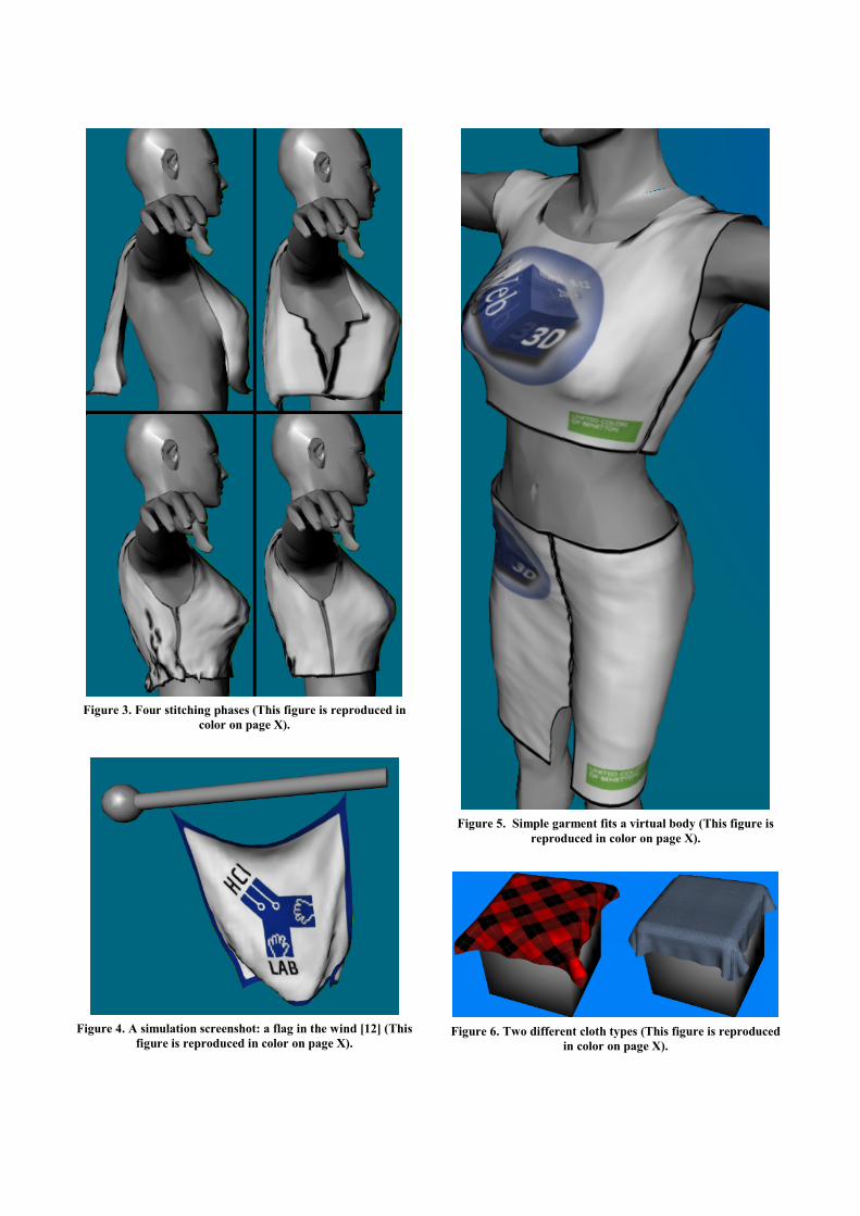
Figure 3. Four stitching phases (This figure is reproduced in
color on page X).
Figure 4. A simulation screenshot: a flag in the wind [12] (This
figure is reproduced in color on page X).
Figure 5. Simple garment fits a virtual body (This figure is
reproduced in color on page X).
Figure 6. Two different cloth types (This figure is reproduced
in color on page X).
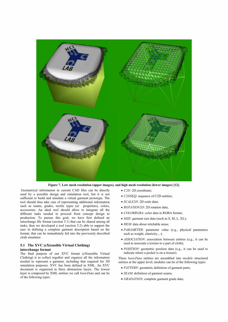
Figure 7. Low mesh resolution (upper images), and high mesh resolution (lower images) [12].
Geometrical information in current CAD files can be directly
used by a possible design and simulation tool, but it is not
sufficient to build and simulate a virtual garment prototype. The
tool should thus take care of representing additional information
such as seams, grades, textile types (or properties), colors,
accessories. An ideal tool should allow to integrate all the
different tasks needed to proceed from concept design to
production. To pursue this goal, we have first defined an
interchange file format (section 5.1) that can be shared among all
tasks; then we developed a tool (section 5.2) able to support the
user in defining a complete garment description based on the
format, that can be immediately fed into the previously described
cloth simulator.
5.1 The XVC (eXtensible Virtual Clothing)
interchange format The final purpose of our XVC format (eXtensible Virtual
Clothing) is to collect together and organize all the information
needed to represent a garment, including that required for 3D
simulation purposes. XVC has been defined in XML. An XVC
document is organized in three abstraction layers. The lowest
layer is composed by XML entities we call basicData and can be
of the following types:
• C2D: 2D coordinate;
• C2DSEQ: sequence of C2D entities;
• SCALE2D: 2D scale data;
• ROTATION2D: 2D rotation data;
• COLORRGBA: color data in RGBA format;
• SIZE: garment size data (such as S, M, L, XL);
• HEM: data about stitchable areas;
• PARAMETER: parameter value (e.g., physical parameters
such as weight, elasticity,...);
• ASSOCIATION: association between entities (e.g., it can be
used to associate a texture to a part of cloth);
• POSITION: geometric position data (e.g., it can be used to
indicate where a pocket is on a trouser).
These basicData entities are assembled into module structured
entities at the upper level; modules can be of the following types:
• PATTERN: geometric definition of garment parts;
• SEAM: definition of garment seams;
• GRADATION: complete garment grade data;
• MATERIAL: data about mechanical textile properties;
• TEXTURE: images to apply on patterns;
• ACCESSORY: information about buttons or other extras.
Finally, the highest layer is composed by XML entities called
containers, that are used to assemble modules or other containers
to define a full garment. For each type of module, there is a
container aimed at grouping together different instances of that
module: for example, several garment parts (each one represented
by a PATTERN module) can be grouped by a PATTERNS
container. GARMENT is the top container of the hierarchy,
representing the unique root of the XML document. Reasons of
space do not allow us to fully describe XVC; in the following, we
illustrate it with an example.
A GARMENT container includes an identification number (ID),
possibly the format version followed by a number of other
containers or modules identified by their IDs. The following is an
example of a possible GARMENT:
<?xml version="1.0" encoding="UTF-8" ?>
- <GARMENT ID="1S001" version="1.0">
+ <PATTERNS ID="1S001.PATTERNS0">
+ <GRADATIONS ID="1S001.GRADATIONS1">
+ <SEAMS ID="1S001.SEAMS2">
+ <TEXTURES ID="1S001.TEXTURES3">
</GARMENT>
Each of the 4 containers in the example includes a number of
corresponding modules. For example, if we expand the
PATTERNS container, we obtain:
<?xml version="1.0" encoding="UTF-8" ?>
- <GARMENT ID="1S001" version="1.0">
- <PATTERNS ID="1S001.PATTERNS0">
+ <PATTERN ID="P01" piecename="…">
+ <PATTERN ID="P02" piecename="…">
+ <PATTERN ID="P03" piecename="…">
</PATTERNS>
+ <GRADATIONS ID="1S001.GRADATIONS1">
+ <SEAMS ID="1S001.SEAMS2">
+ <TEXTURES ID="1S001.TEXTURES3">
</GARMENT>
where three modules of type PATTERN are identified by their
IDs. If we expand one of the patterns we obtain a number of 2D
coordinate sequences. The following listing shows an expansion
of the P01 pattern and of two of its enclosed coordinate
sequences:
<?xml version="1.0" encoding="UTF-8" ?>
- <GARMENT ID="1S001" version="1.0">
- <PATTERNS ID="1S001.PATTERNS0">
- <PATTERN ID="P01" piecename="…">
- <C2DSEQ ID="C01">
<C2D x="-31.226" y="0.0" />
</C2DSEQ>
- <C2DSEQ ID="C02">
<C2D x="-32.347" y="24.307" />
<C2D x="-33.742" y="48.593" />
</C2DSEQ>
+ <C2DSEQ ID="C03">
+ <C2DSEQ ID="C04">
+ <C2DSEQ ID="C05">
+ <C2DSEQ ID="C06">
+ <C2DSEQ ID="C07">
</PATTERN>
+ <PATTERN ID="P02" piecename="…">
+ <PATTERN ID="P03" piecename="…">
</PATTERNS>
+ <GRADATIONS ID="1S001.GRADATIONS1">
+ <SEAMS ID="1S001.SEAMS2">
+ <TEXTURES ID="1S001.TEXTURES3">
</GARMENT>
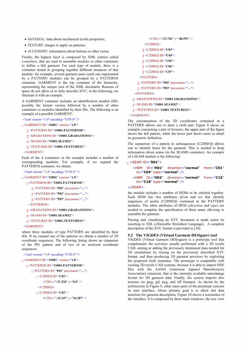
The concatenation of the 2D coordinates contained in a
PATTERN allows one to draw a cloth part. Figure 8 shows an
example concerning a part of trousers; the upper part of the figure
shows the full pattern, while the lower part shows more in detail
its geometric definition.
The separation of a pattern in subsequences (C2DSEQ) allows
one to identify hems for the garment. This is needed to keep
information about seams (in the SEAMS container). An example
of a SEAM module is the following:
- <SEAM ID="S01">
<HEM ID="H01" direction="normal" from="C01"
to="C04" type="normal" />
<HEM ID="H02" direction="normal" from="C15"
to="C18" type="normal" />
</SEAM>
the module includes a number of HEMs to be stitched together.
Each HEM has two attributes (from and to) that identify
sequences of points (C2DSEQ) contained in the PATTERN
modules. The other attributes of HEM (direction and type) are
needed to complete the specification of them seam, allowing to
assemble the garment.
Parsing and visualizing an XVC document is made easier by
resorting to XSL (eXtensible Stylesheet Language). A complete
description of the XVC format is provided in [10].
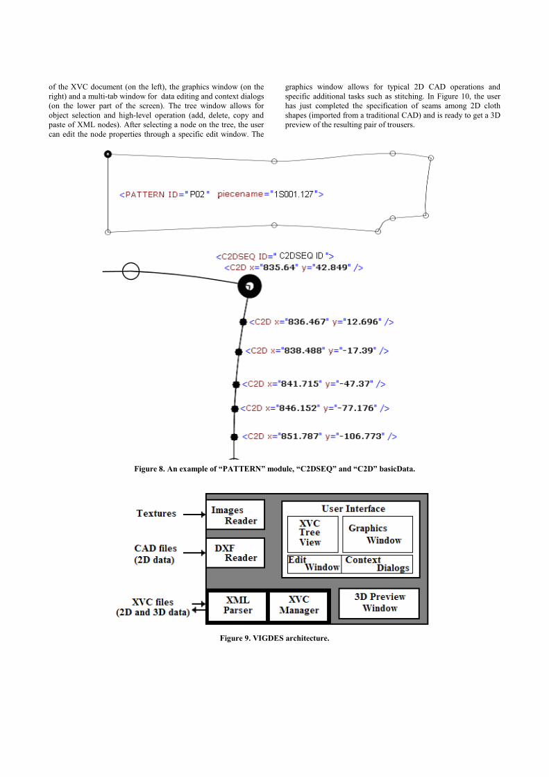
5.2 The VIGDES (VIrtual Garment DESigner) tool VIGDES (VIrtual Garment DESsigner) is a prototype tool that
complements the activities usually performed with a 2D textile
CAD, aiming at adding the previously mentioned data needed for
3D simulations by relying on the previously described XVC
format, and then producing 3D garment previews by exploiting
the proposed cloth simulator. The prototype is compatible with
existing 2D textile CAD systems, because it is able to import DXF
files with the AAMA (American Apparel Manufacturers
Association) extension, that is the currently available interchange
format for 2D garment data. Finally, the system imports also
textures (in jpeg, gif, png, and tiff formats). As shown by the
architecture in Figure 9, other main parts of the prototype concern
its user interface, whose primary goal is to allow fast data
insertion for garment description. Figure 10 shows a screenshot of
the interface. It is composed by three main windows: the tree view
of the XVC document (on the left), the graphics window (on the
right) and a multi-tab window for data editing and context dialogs
(on the lower part of the screen). The tree window allows for
object selection and high-level operation (add, delete, copy and
paste of XML nodes). After selecting a node on the tree, the user
can edit the node properties through a specific edit window. The
graphics window allows for typical 2D CAD operations and
specific additional tasks such as stitching. In Figure 10, the user
has just completed the specification of seams among 2D cloth
shapes (imported from a traditional CAD) and is ready to get a 3D
preview of the resulting pair of trousers.
Figure 8. An example of “PATTERN” module, “C2DSEQ” and “C2D” basicData.
Figure 9. VIGDES architecture.
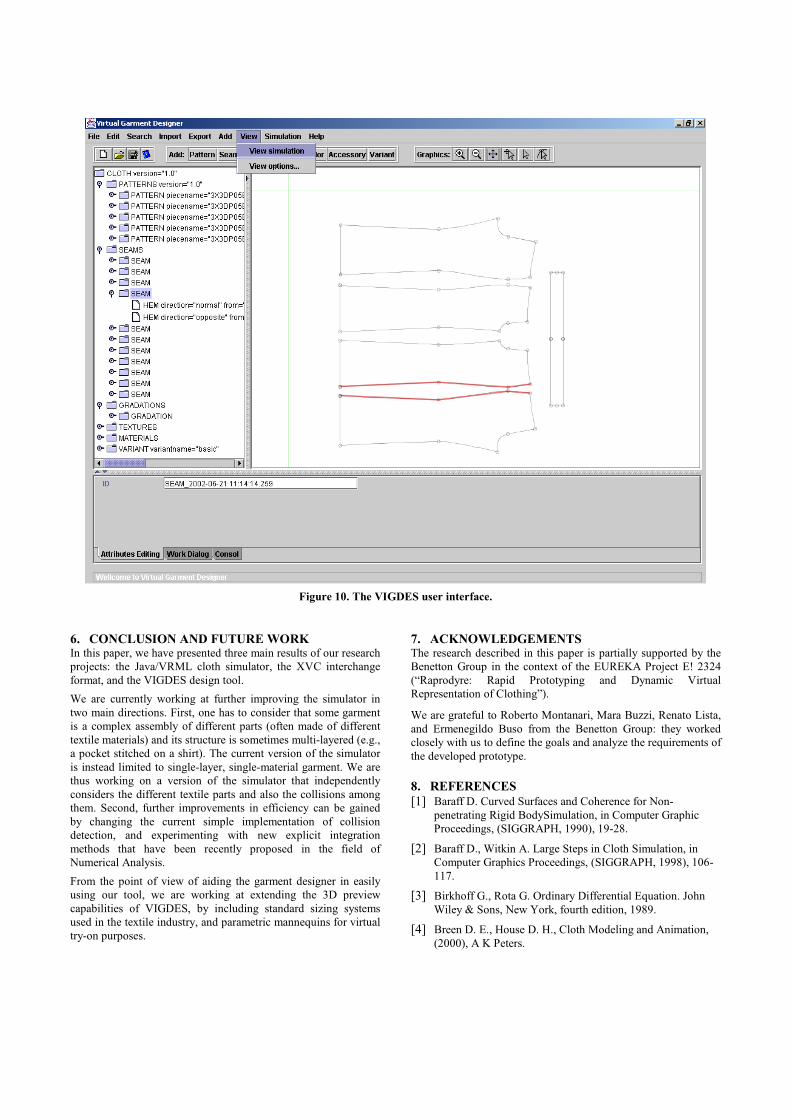
Figure 10. The VIGDES user interface.
6. CONCLUSION AND FUTURE WORK In this paper, we have presented three main results of our research
projects: the Java/VRML cloth simulator, the XVC interchange
format, and the VIGDES design tool.
We are currently working at further improving the simulator in
two main directions. First, one has to consider that some garment
is a complex assembly of different parts (often made of different
textile materials) and its structure is sometimes multi-layered (e.g.,
a pocket stitched on a shirt). The current version of the simulator
is instead limited to single-layer, single-material garment. We are
thus working on a version of the simulator that independently
considers the different textile parts and also the collisions among
them. Second, further improvements in efficiency can be gained
by changing the current simple implementation of collision
detection, and experimenting with new explicit integration
methods that have been recently proposed in the field of
Numerical Analysis.
From the point of view of aiding the garment designer in easily
using our tool, we are working at extending the 3D preview
capabilities of VIGDES, by including standard sizing systems
used in the textile industry, and parametric mannequins for virtual
try-on purposes.
7. ACKNOWLEDGEMENTS The research described in this paper is partially supported by the
Benetton Group in the context of the EUREKA Project E! 2324
(“Raprodyre: Rapid Prototyping and Dynamic Virtual
Representation of Clothing”).
We are grateful to Roberto Montanari, Mara Buzzi, Renato Lista,
and Ermenegildo Buso from the Benetton Group: they worked
closely with us to define the goals and analyze the requirements of
the developed prototype.
8. REFERENCES
[1] Baraff D. Curved Surfaces and Coherence for Non-
penetrating Rigid BodySimulation, in Computer Graphic
Proceedings, (SIGGRAPH, 1990), 19-28.
[2] Baraff D., Witkin A. Large Steps in Cloth Simulation, in
Computer Graphics Proceedings, (SIGGRAPH, 1998), 106-
117.
[3] Birkhoff G., Rota G. Ordinary Differential Equation. John
Wiley & Sons, New York, fourth edition, 1989.
[4] Breen D. E., House D. H., Cloth Modeling and Animation,
(2000), A K Peters.

[5] Breen D.E., House D.H., Getto P.H. A Physical-Based
Particle Model of Woven Cloth, in Visual Computer, (1992)
264-277.
[6] Carignan M., Yang Y., Magnenat-Thalmann, Thalmann D.
Dressing Animated Synthetic Actors with Complex
Deformable Clothes, in Computer Graphics Proceedings,
(ACM SIGGRAPH, 1992), 99-104.
[7] Coddington E. A., Levinson N. Theory pf Ordinary
Differential Equations. McGraw-Hill, New York, 1966.
[8] Eberhardt B., Weber A., Strasser W. A fast, flexible,
Particle-System for Cloth Draping, in Computer Graphics in
Textiles and Apparel (IEEE Computer Graphics And
Application), (September, 1996), 52-59.
[9] Eishen J.W., Deng S., Clapp T.G., Finite-Element Modeling
and Control of Flexible Fabric Parts, in Computer Graphics
in Textiles and Apparel, (IEEE Computer Graphics and
Applications, September 1996), 71-80.
[10] Extensible Virtual Clothing (XVC) Format Specifications,
version 1.0, Technical Report, Eureka Project E!2324
“Raprodyre”, 2002.
[11] Gerber Technology. http://www.gerbertechnology.com
[12] HCI Lab, Cloth Simulation Page, University of Udine,
http://hcilab.uniud.it/cloth3d.jsp
[13] Investronica Sistemas. http://www.invescol.com
[14] Kawabata S. The Standardization of Hand Evaluation. The
Textile Machinary Society of Japan, Osaka, 1975.
[15] Provot X., Collision and Self-Collision Handling in Cloth
Model to Dedicated to Design Garments, in Graphic
Interface proceedings, Canadian Information Processing
Society, Canadian Human-Computer Communications
Society, (May 1997), 177-189.
[16] Provot X., Deformation Constrains in a Mass-Spring Model
to Describe Rigide Cloth Behavior, in Graphic Interface
proceedings, (Quebec City, Canada, 1995), 147-154.
[17] Rosenbloom, A. (ed.) Special issue on Physically-based
Computer Animation. Communications of the ACM, 43(7),
2000.
[18] Terzopoulos D., Platt J., Barr A., Fleischer K. Elastic
deformable models, in Computer Graphics Proceedings,
Annual Conference Series, (New York, ACM SIGGRAPH,
July 1987), 205-214.
[19] Vassilev, T. I, Dressing Virtual People, in SCI'2000
conference, (Orlando, July 2000), 23-26.
[20] Volino P., Courchesne M., Magnenat-Thalmann N. Versatile
and Efficient Techniques for Simulating Cloth and other
Deformable Objects, in proceedings Siggraph '95, (1995),
137-144.
[21] Volino P., Magnenat-Thalmann N, Efficient Self-Collision
Detection on Smoothly Discretized Surface Animations
using Geometrical Shape Regularity, in Proceedings
Eurographics '94, Computer Graphics Forum, (1994).
[22] Volino P., Magnenat-Thalmann N. Accurate Collision
response on polygonal Meshes, in Computer Animation
Conference, (Philadelphia, May 2000).
[23] Volino P., Magnenat-Thalmann N. Comparing Efficiency of
Integration Methods for Cloth Animation, in Proceedings of
CGI'01, (Hong-Kong, July 2001).
[24] Volino P., Magnenat-Thalmann N., Developing Simulation
Techniques for an Interactive Clothing System in
Proceedings VSMM'97, (Geneva, Switzerland, 1997), 109-
118.
[25] Volino P., Magnenat-Thalmann N., Implementing fast Cloth
Simulation with Collision Response, in Computer Graphics
International, (June 2000).
[26] Volino P., Magnenat-Thalmann N., Jianhua S., Thalmann D.,
The Evolution of a 3D System for Simulating Deformable
Clothes on Virtual Actors, in IEEE Computer Graphics and
Applications, (September 1996), 42-50.
[27] Weil J. The synthesis of cloth objects, in Proceedings
Computer Graphic, Annual Conference Series, (ACM
SIGGRAPH, August 1986), 49-53.


![CloTH-VTON: Clothing Three-dimensional reconstructionfor ......reconstruct 3D clothing from images for 3D VTON, leveraging garment meshes from MGN [2]. Our work is most similar to](https://img.dokumen.tips/doc/110x75/60b89d7300939e46ff0a380f/cloth-vton-clothing-three-dimensional-reconstructionfor-reconstruct-3d.jpg)