Embed Size (px)
Citation preview
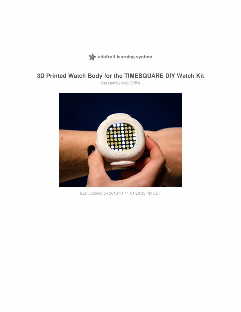
3D Printed Watch Body for the TIMESQUARE DIY Watch KitCreated by Matt Griffin
Last updated on 2013-11-11 01:30:33 PM EST
25566667999
1010101012121213131414141616161617171818
Guide Contents
Guide ContentsOverview
Before You Get StartedTools
You'll need:Optional tools:Selecting 3D CAD / Modeling SoftwareSelecting a 3D Printer:
Creating a 3D Model2. Sketching the Watch Body3. Modeling the Faceplate4. Adding Buttons5. Preparing for Wrist Straps6. Modeling the BackplateA Few General Modeling Tips
1. Create A Dummy ObjectGOAL:Research Available Measurements ("Cheat")Creating Orthographic Projections (The Three Views)Plan for Insertion of PartsSimplify Geometry to What Is RelevantPlan to Accomodate Mechanical TolerancesYou Are Making Two (Three) Digital Dummies, Not Just One
2. Sketching the Watch BodyGOALS:Identify Where Your Design Interfaces wIth DummyCommit to a Design ConceptTrace Sketch with Vector Illustration Tool For Reference Markers for 3D Modeling.Break Down Complicated Shapes Into Primitive Solids
3. Modeling the FaceplateGOALS:
© Adafruit Industries http://learn.adafruit.com/3d-printed-enclosure-for-the-timesquare-diy-watch-kit
Page 2 of 29
18181919192020212222222223232324242424242526262626262728282828282929
Create Reference "Cage"Triangulate Placement Using Orthographic ProjectionsUse Many Layers (Duplicating, Locking, Hiding)Construct Complicated Shapes From Primitive SolidsBuild Details Using Points, Curves, SurfacesGrouping vs JoiningBoolean Operations - As Late As PossiblePrinting Test Parts / Insertion Test
4. Adding ButtonsGOALS:Trapped Button CapsWireframe Routing TipCreating Button CageCreating Buttons and Button Cutting ToolPrinting Button Tests
5. Preparing for Wrist Straps5. Preparing for Wrist Straps (http://adafru.it/aW3)Build In Flexibility for Range of SizesOverhangs and Support MaterialSnap-fit PlanningPrinting Strap Tests
6. Modeling the BackplateGOALSScale and OffsetPlanning for MaterialsAccomodate Range of Wrist SizesPrinting Backplate Tests
Printing and Proofing Your ModelsPrint Often, Learn through PrintingClean up and Fit TestingAdjusting Your DesignSurface Finishing Techniques
Sharing Your DesignThingiverse
© Adafruit Industries http://learn.adafruit.com/3d-printed-enclosure-for-the-timesquare-diy-watch-kit
Page 3 of 29

2929
Did you print out a copy of the "Circling the Square" watch body?Did you use these resources to create your own watch body design?
© Adafruit Industries http://learn.adafruit.com/3d-printed-enclosure-for-the-timesquare-diy-watch-kit
Page 4 of 29

Overview
Love the TIMESQUARE DIY Watch kit (http://adafru.it/1106) and have a great idea for a customwatch body you would like to fabricate to house the electronic parts? The watch kit alreadyships with style to spare, but that's no reason to limit yourself to the included watch band whenyou can make one.
Here are the steps I took to create the "Circling the Square" TIMESQUARE WatchBody (http://adafru.it/aVN). As I guide you through the steps I followed, I will share plenty of tipsand tricks for how you can design your own!
Take advantage of the tools I created for this model kit to help you design faster! Check outthis TIMESQUARE Sketch Guide (PDF) (http://adafru.it/aVO) that you can use to sketch out yourideas. Or download this TIMESQUARE Dummy (STL) (http://adafru.it/aVP) object to import intoyour modeling tool as a handy reference -- or as a boolean operations tool to punch anelectronics cavity into another object you have designed!
Before You Get StartedPrepare the watch electronics first. Check out Ladyada's Learning System tutorial:TIMESQUARE Watch Kit (http://adafru.it/aTa).
Print a test object from your design software. As a first stage to design, create andexport a small file with easy to measure parts on x, y, and z axes. Print this as early in theprocess as possible and use digital calipers to measure how the physical object compares tothe measurement settings in your digital design file.
© Adafruit Industries http://learn.adafruit.com/3d-printed-enclosure-for-the-timesquare-diy-watch-kit
Page 5 of 29
Tools
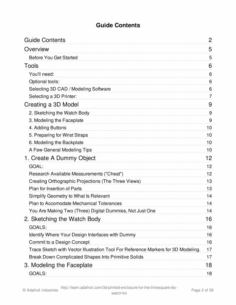
You'll need:
Completed TIMESQUARE DIYWatch (http://adafru.it/1106) electronics.Make sure to solder componentsclose and tidy on the board to makeinserting into enclosure easier.
Dependable digital calipers. Werecommend the indestructable andultra-precise Mitutoyo - AbsoluteDigimatic DigitalCalipers (http://adafru.it/294), but youcan get by with a less expensive setin a pinch.
3D CAD / Modeling softwarepackage. See below for tips on howto select your software.
Desktop 3D printer or printingservice. See below for tips on howto select your printer.
Optional tools:
Vector-based 2D modelingsoftware. Create vector-basedsketchs using the TIMESQUARESketchGuide.pdf (http://adafru.it/aVO) in2D illustration software and you canimport your sketch layers right intoyour 3D modeling tool as referenceguides.
Drafting tools: gridpaper, straight edge, compass,protractor. Gaining physical draftingskills can be handy when buildingenclosures around irregular real worldobjects -- and a great way to getideas for how to build your modelfrom primitive solids.
Surface finishingtools: sandpaper, pliers, plasticpolishing compound, solvents,and rotary tools. Your projectmight require nothing more than alittle brush-up after the final print, butfor some designers, when the finalprinted parts are ready, the project isonly half complete.
Selecting 3D CAD / Modeling Software
© Adafruit Industries http://learn.adafruit.com/3d-printed-enclosure-for-the-timesquare-diy-watch-kit
Page 6 of 29
For this project, I selected Rhino OSX (http://adafru.it/aVQ) (work-in-progress) because it is adependable, affordable solution for transforming my reference sketches into surfaces.Particularly useful are dimensional and object "snaps" (ways to lock elements to eachother according to user-selected criteria) to ensure that I can build parts separately, joiningthem at a later stage in the design.
You might might have equal luck with another solution, from open source apps suchas Blender (http://adafru.it/aVR),Wings3D (http://adafru.it/aVS), and OpenSCAD (http://adafru.it/aVT) to free options suchas TinkerCAD (http://adafru.it/aVU) 123D Design (http://adafru.it/aVV),and Sketchup (http://adafru.it/aVW) Other popular commercial modeling toolsincludes Solidworks, Maya, modo, AutoCAD, and 3DS Max.
Here are a few specs to consider when selecting a solid modeling tool for 3D printing:
Dimensionally accurate. 2D vectors and 3D models can be imported and exported andwill remain precisely the same all the way through a project.
Multiple layers that can be shown, hidden, and locked. While versioning thedesign file itself is essential, the ability to break up the parts of your design into multiplelayers allows you to keep around reference curves from earlier stages in the design to helpyou make adjustments later in the design process.
Ability to create objects from points, curves, surfaces, and solids -- andexplode them back into the faces, curves, and points they are made from.
Grid and object snaps. Grid snaps are handy for making approximations early andlate in the design process to adjust to the real world. Object snaps should be userconfigurable and aid the designer with establishing clear relationships between parts of amodel: this line is a tangent to this curve, this surface is perpendicular to that surface, thispoint is the center of this circular object, etc..
Ability to export manifold STL mesh models directly. While there are plenty ofhandy tools such as Meshlab (http://adafru.it/aVX) to import files from a variety of computergraphics formats (cloud data, obj, stl, etc.), having an export option to create from yourdesign software directly what your 3D Printing software / CAM requires reduces thecomplexity of the process. (Luckily, formats like STL are very old and most CAD softwaresupports it.)
Selecting a 3D Printer:I used a MakerBot Replicator 1 and Replicator 2 for this project, but every day, new affordabledesktop 3D printers are released that offer the qualities you need to print electronicsenclosures efficiently and inexpensively. As a reference to help you select one, considerthe MAKE Ultimate Guide to 3D Printing (http://adafru.it/aVY), to which I contributed.
Here are characteristics to consider when selecting a desktop 3D printer:
Layer height. Often described as "resolution" or "z-axis resolution.
Thread width. How wide is the filament extrusion coming out of the extruder nozzle? (Orin other methods of 3D printing, the grain size for powder printers and x-/y- axis resolutionfor laser and UV curing projects. This factor affects the size of "smallest discernable detail"which affects how thin walls and details can be on the surface of objects in terms of x-/y-axis.
Layer-to-layer registration. When looking at a printed part, are there pronounced layerridges or do flat/smooth parts only have layers upon close inspection? The moredependable desktop printers are designed to make sure registration is accurate to allowfor smooth, organic curved surfaces.
Repeatability. From job to job, do the calibration settings and dimensions of the resultsremain the same within a very narrow tolerance? The best way to learn this is to consult alongtime user of the machine. User-assembled kits tend to require user expertise with apainstaking process of establishing a baseline configuration -- but gaining this experiencewith your printer can allow for more control over print job settings.
Print materials. Will the print material handle the heat, weight, torquing, pressure, seal,etc. that you require from your final piece? And most importantly, how will this material
© Adafruit Industries http://learn.adafruit.com/3d-printed-enclosure-for-the-timesquare-diy-watch-kit
Page 7 of 29

interact with the other elements you need to place up against it and to the process of gluingtwo parts of this material together?
For printing services, contact your local hackerspaces and university fab labs or visitthe Shapeways (http://adafru.it/aVZ) or Ponoko (http://adafru.it/aW0) services online to haveyour final models shipped to you.
© Adafruit Industries http://learn.adafruit.com/3d-printed-enclosure-for-the-timesquare-diy-watch-kit
Page 8 of 29

Creating a 3D Model
Here are the steps I took to create the "Circling the Square" watch body. Click any of the stage titles to head directly to that subtopic.
1. Create A Dummy ObjectTake detailed measurements of theelectronics parts to be inserted into the watchbase and create an accurate 3D model thatmatches its real world counterpart whenproduced by the intended desktop 3D printer.
Techniques Learned:Research Available Measurements("Cheat")Creating Orthographic Projections (The SixViews)Plan for Insertion of PartsSimplify Geometry to What Is RelevantPlan to Accomodate MechanicalTolerancesYou Are Making Two (Three) DigitalDummies, Not Just One
2. Sketching the Watch Body
Leaning on the accurate model produced forthe dummy object, sketch out ideas for thewatch body design and take notes how youdesign references the electronic parts.
Techniques Learned:Commit to a Design ConceptIdentify Where Your Design Interfaces wIthDummyTrace Sketch with Vector Illustration ToolFor Reference Markers for 3D Modeling.Break Down Complicated ShapesInto Primitive Solids
3. Modeling the Faceplate
Import sketches for faceplate into 3DCAD tool and use reference measurementsand notes where parts interface to model thefirst part of the watch body.
Techniques Learned:Create Reference "Cage"Triangulate Placement Using OrthographicProjectionsUse Many Layers (Duplicating, Locking,Hiding)Construct Complicated Shapes FromPrimitive Solids Build Details Using Points, Curves,Surfaces.Grouping vs JoiningBoolean Operations - As Late As PossiblePrinting Test Parts; Insertion Test
© Adafruit Industries http://learn.adafruit.com/3d-printed-enclosure-for-the-timesquare-diy-watch-kit
Page 9 of 29
A Few General Modeling TipsWhile I will mention many of these elsewhere in this guide, it is worth gathering here the generalmodeling tips you will return to again and again.
Print a test object from your design software. As a first stage to design, createand export a small file with some easy to measure parts on x, y, and z axes. Print this asearly in the process as possible and use digital calipers to measure how the physical objectcompares to the measurement settings in your digital design file.Use Many Layers. Get to know the layers in your application and develop a practice ofduplicating all of the elements that you will use for joins, Create "Reference Layers." The simple points, curves, and surfaces that you use toproduce solid parts by combining, lofting, slicing, and boolean operations are of crucialvalue later in the design process as a reference for how you created complex shapes.Create separate reference layers and copy and paste the elements you use as toolsbefore running operations on them so that you can retrieve them later if something goeswrong and you need to roll back the clock.Build a Mechanical Tolerance Plan. Anytime you use a fabrication tool to produce aphysical object from a digital design, there are slight differences between the "ideal" digitalmodel and the accuracy of the machine used to create the printed object. When you createprinted parts that interface with real world objects you need to plan to accomodate this bygetting to know the technical specs for your machine and job settings -- and by printingfrequently. See "Creating a Dummy Object (http://adafru.it/aW1)" for a great practicalexample.Create "Reference Cages." You will find that you will create geometry separate from
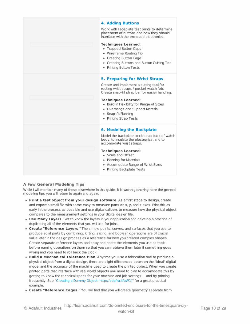
4. Adding Buttons
Work with Faceplate test prints to determineplacement of buttons and how they shouldinterface with the enclosed electronics.
Techniques Learned:Trapped Button CapsWireframe Routing TipCreating Button CageCreating Buttons and Button Cutting ToolPrinting Button Tests
5. Preparing for Wrist Straps
Create and implement a cutting tool forrouting wrist straps / pocket watch fob.Create snap-fit strap bar for easier handling.
Techniques Learned:Build In Flexibility for Range of SizesOverhangs and Support MaterialSnap-fit PlanningPrinting Strap Tests
6. Modeling the Backplate
Model the backplate to closeup back of watchbody, to insulate the electronics, and toaccomodate wrist straps.
Techniques Learned:Scale and Offset Planning for MaterialsAccomodate Range of Wrist SizesPrinting Backplate Tests
© Adafruit Industries http://learn.adafruit.com/3d-printed-enclosure-for-the-timesquare-diy-watch-kit
Page 10 of 29
your design primarily as a reference for position, compare, or separate objects. A good"reference cage" includes both geometry to reference the "dummy object" and workplaneand the workplane of the object being modeled. (Here's a hint -- a reference cage for acavity emphasizes the points and curves inset from boundary between cavity and dummywhile a reference cage for an outer surface emphasizes the points and curves offset fromthe boundary of the object.) Learn the keyboard commands. You will rarely use all of the modeling tools from aCAD package within one project, just a small subset. Learning the keyboard commandswon't just speed up the process of modeling, it will help keep you in more intuitive creativemindset than if you are constantly stopping to mouse over to a menu item.Print Often, Measure Once, Twice, Thrice! Take every opportunity to print yourmodel, or parts of your model, available to you. You will learn quite a bit about your modelby holding it physically in your hand. And if you use each opportunity to measure andcompare your real world model to your digital one, you will make sure you detect fasterwhether any of your modeling operations has shifted your design off of the baseline youestablished creating the dummy object.Print Parts of your Model. To save time and print material, it is worth creating newlayers with version of your project that are trimmed down to only the element you arecurrently working on, so that you can export and print those. Examples include how a buttonand button cavity will function. Adjust your model, not your job settings. While it is tempting to tweak your printjob settings with lots of tiny scale and position changes in your CAM tool to just "make itwork," those you share your printable model with after the design process will not benefitfrom what you learned about your model from printing it unless you go back into the designfile and make adjustments there, upstream from your printable files.Fused Filament Fabrication prints shrink as they cool. And by a factor of about1%-2%, depending on your plastic vendor. You will get the hang of this over time, but aslong as you accomodate this when planning for engineering tolerances your design shouldremain accurate to the world.
© Adafruit Industries http://learn.adafruit.com/3d-printed-enclosure-for-the-timesquare-diy-watch-kit
Page 11 of 29

1. Create A Dummy Object
GOAL:Take detailed measurements of the electronics parts to be inserted into thewatch base and create an accurate 3D model that matches its real worldcounterpart when produced by the intended desktop 3D printer.
The first (often overlooked) stage for the design of a 3D enclosure, model, or bezel: measureyour electronics and create a digital "dummy" object that is an accurate match for it's real worldcounterpart.
The creation of dummy objects is a long-standing tradition from the world of fashion, craft, andindustry -- typically used to optimize how multiples of an object will be assembled. Thisprocess has added relevance to the digital designer within the wider open source / openhardware culture of today:
Make use of the efforts of other people who have tackled these components before you.Share back digital models to help others print and tune your project for other, novelpurposes.Why should anyone recreate the wheel when they can make a better functioning, betterlooking wheel by studying the wheels of others?
It is worth going through the process of re-making your physical objects in the digital world sothat you can take the measurements you need to discover essential shape and positioninformation to help you construct an artful, intentional design to interface with it!
Research AvailableMeasurements ("Cheat")
Depending on the electronicscomponents you want to enclose ormount, there may already be resourcesavailable online to help you speed up thisstage. There are benefits to huntingfor existing models: you can test andreport back whether the model isaccurate enough and you can meetdesigners who are also working with thecomponents you selected -- anopportunity for exchanging models andgetting feedback.
Great places to hunt for resources:Product datasheets and tech specs.
© Adafruit Industries http://learn.adafruit.com/3d-printed-enclosure-for-the-timesquare-diy-watch-kit
Page 12 of 29

Thingiverse and other objectrepositories.Project pages for the PCBs --including resources such asFritzing.org where vector models arenecessarily accurately scaled.Electronics component suppliers.
And here's a great place to "cheat" forthe TIMESQUARE project:
TIMESQUARE_SketchGuide.PDF (http://adafru.it/aVO) -- 2D Vector illustration TIMESQURE_dummy.stl (http://adafru.it/aVP) -- 3D mesh model
When you are done with the process ofmeasuring your components and makingyour dummy part(s) -- you shouldstrongly consider including your dummyobject with the community as well asyour final model.
Creating OrthographicProjections (The Three Views)
One handy time-tested approach tocapturing accurate model data is to takemeasurements and sketch out the topfront and right sides of the object as"orthogonal views" (ie eliminate theforeshortening ).
If it is helpful, do all six views (think interms of all of the faces of 6-sideddice).Isometric projections can be helpful,particularly for recording referencesfor how the elements match up.Performing them accurately is a realskill (or a keypress in expensive CADsoftware) but might not benecessary.Record notes about where parts ofthese views match up to each other.Plan in terms of the software's objectsnap options.
Plan for Insertion of Parts
A cavity for your electronics is no good ifyou can't place parts in there.
© Adafruit Industries http://learn.adafruit.com/3d-printed-enclosure-for-the-timesquare-diy-watch-kit
Page 13 of 29
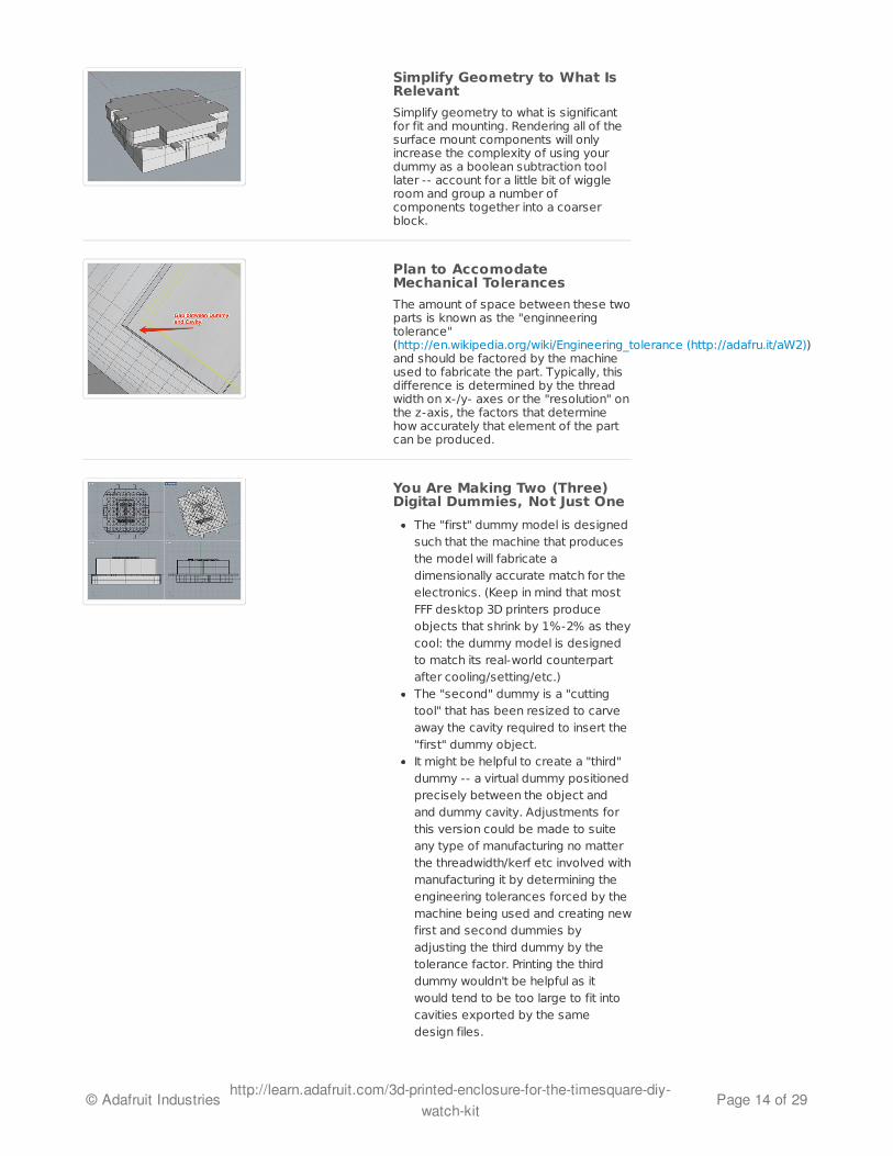
Simplify Geometry to What IsRelevant
Simplify geometry to what is significantfor fit and mounting. Rendering all of thesurface mount components will onlyincrease the complexity of using yourdummy as a boolean subtraction toollater -- account for a little bit of wiggleroom and group a number ofcomponents together into a coarserblock.
Plan to AccomodateMechanical Tolerances
The amount of space between these twoparts is known as the "enginneeringtolerance"(http://en.wikipedia.org/wiki/Engineering_tolerance (http://adafru.it/aW2))and should be factored by the machineused to fabricate the part. Typically, thisdifference is determined by the threadwidth on x-/y- axes or the "resolution" onthe z-axis, the factors that determinehow accurately that element of the partcan be produced.
You Are Making Two (Three)Digital Dummies, Not Just One
The "first" dummy model is designedsuch that the machine that producesthe model will fabricate adimensionally accurate match for theelectronics. (Keep in mind that mostFFF desktop 3D printers produceobjects that shrink by 1%-2% as theycool: the dummy model is designedto match its real-world counterpartafter cooling/setting/etc.)The "second" dummy is a "cuttingtool" that has been resized to carveaway the cavity required to insert the"first" dummy object. It might be helpful to create a "third"dummy -- a virtual dummy positionedprecisely between the object andand dummy cavity. Adjustments forthis version could be made to suiteany type of manufacturing no matterthe threadwidth/kerf etc involved withmanufacturing it by determining theengineering tolerances forced by themachine being used and creating newfirst and second dummies byadjusting the third dummy by thetolerance factor. Printing the thirddummy wouldn't be helpful as itwould tend to be too large to fit intocavities exported by the samedesign files.
© Adafruit Industries http://learn.adafruit.com/3d-printed-enclosure-for-the-timesquare-diy-watch-kit
Page 14 of 29

Print your dummy object and check itwith accurate calipers.Does it match your model?Adjust until it does.
© Adafruit Industries http://learn.adafruit.com/3d-printed-enclosure-for-the-timesquare-diy-watch-kit
Page 15 of 29
2. Sketching the Watch Body
GOALS:Leaning on the accurate model produced for the dummy object, sketch out ideas for the watchbody design and take notes how you design references the electronic parts.
From hand draw notes to vector-based illustration ready to drop into your CAD application, anypathway you find to capture your ideas to aid you during the 3D modeling process isacceptable. However, when making a tight enclosure for electronics I find it is helpful to do yoursketching at this stage in the order: after creating your "dummy" object.
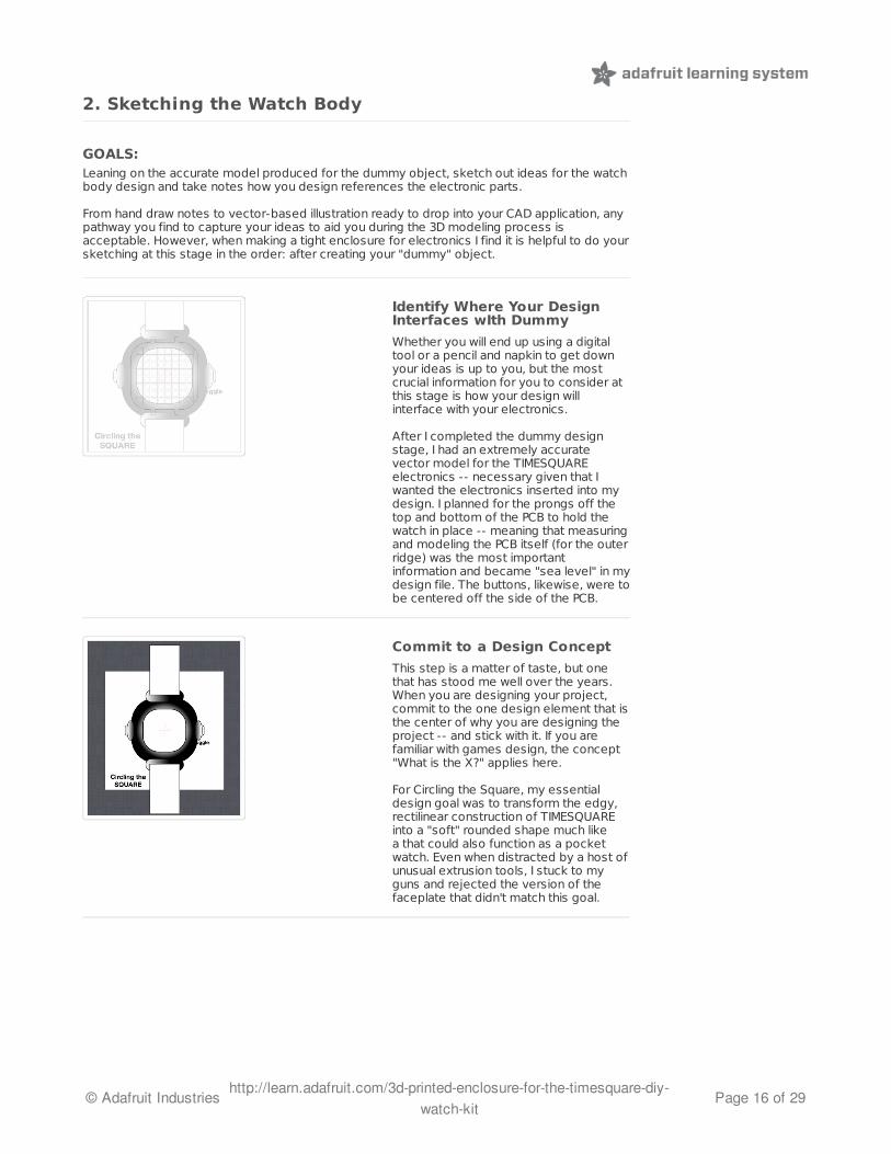
Identify Where Your DesignInterfaces wIth Dummy
Whether you will end up using a digitaltool or a pencil and napkin to get downyour ideas is up to you, but the mostcrucial information for you to consider atthis stage is how your design willinterface with your electronics.
After I completed the dummy designstage, I had an extremely accuratevector model for the TIMESQUAREelectronics -- necessary given that Iwanted the electronics inserted into mydesign. I planned for the prongs off thetop and bottom of the PCB to hold thewatch in place -- meaning that measuringand modeling the PCB itself (for the outerridge) was the most importantinformation and became "sea level" in mydesign file. The buttons, likewise, were tobe centered off the side of the PCB.
Commit to a Design Concept
This step is a matter of taste, but onethat has stood me well over the years.When you are designing your project,commit to the one design element that isthe center of why you are designing theproject -- and stick with it. If you arefamiliar with games design, the concept"What is the X?" applies here.
For Circling the Square, my essentialdesign goal was to transform the edgy,rectilinear construction of TIMESQUAREinto a "soft" rounded shape much likea that could also function as a pocketwatch. Even when distracted by a host ofunusual extrusion tools, I stuck to myguns and rejected the version of thefaceplate that didn't match this goal.
© Adafruit Industries http://learn.adafruit.com/3d-printed-enclosure-for-the-timesquare-diy-watch-kit
Page 16 of 29
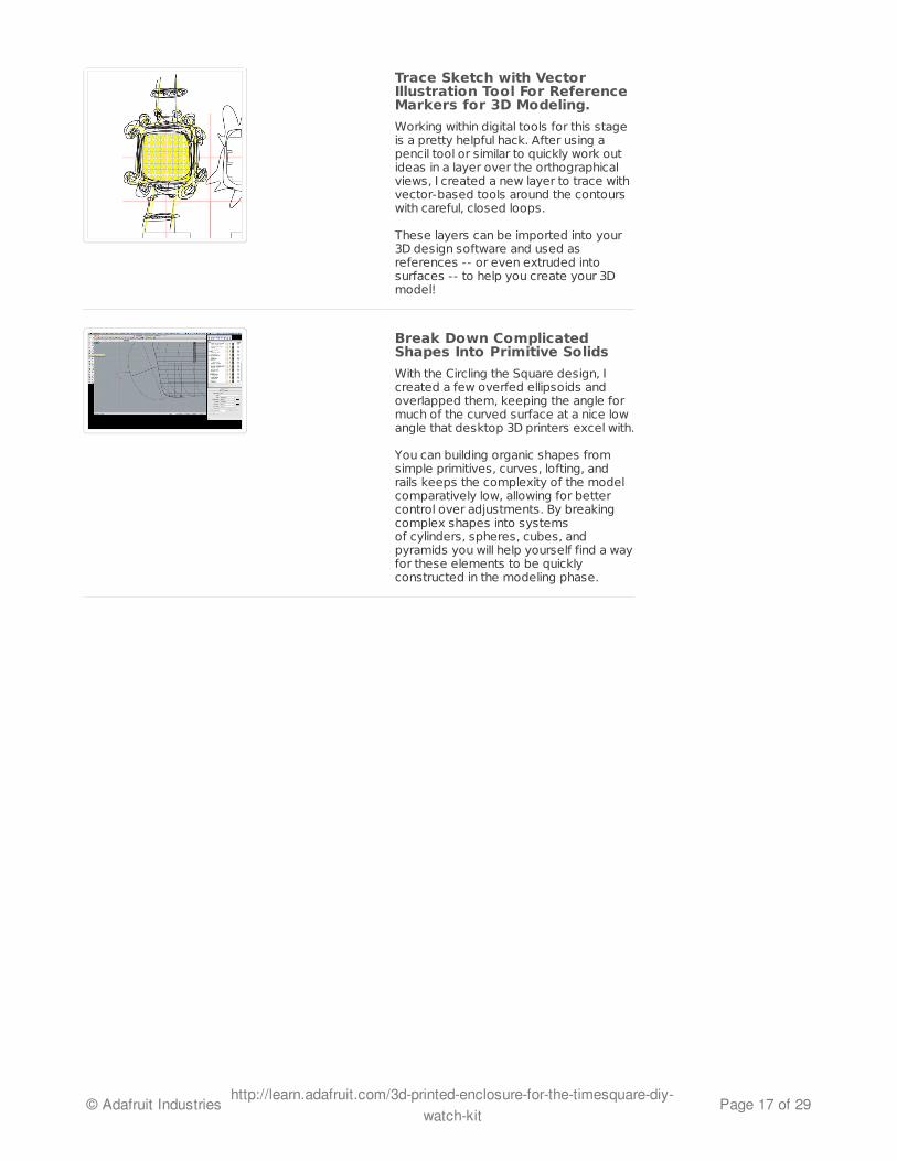
Trace Sketch with VectorIllustration Tool For ReferenceMarkers for 3D Modeling.
Working within digital tools for this stageis a pretty helpful hack. After using apencil tool or similar to quickly work outideas in a layer over the orthographicalviews, I created a new layer to trace withvector-based tools around the contourswith careful, closed loops.
These layers can be imported into your3D design software and used asreferences -- or even extruded intosurfaces -- to help you create your 3Dmodel!
Break Down ComplicatedShapes Into Primitive Solids
With the Circling the Square design, Icreated a few overfed ellipsoids andoverlapped them, keeping the angle formuch of the curved surface at a nice lowangle that desktop 3D printers excel with.
You can building organic shapes fromsimple primitives, curves, lofting, andrails keeps the complexity of the modelcomparatively low, allowing for bettercontrol over adjustments. By breakingcomplex shapes into systemsof cylinders, spheres, cubes, andpyramids you will help yourself find a wayfor these elements to be quicklyconstructed in the modeling phase.
© Adafruit Industries http://learn.adafruit.com/3d-printed-enclosure-for-the-timesquare-diy-watch-kit
Page 17 of 29
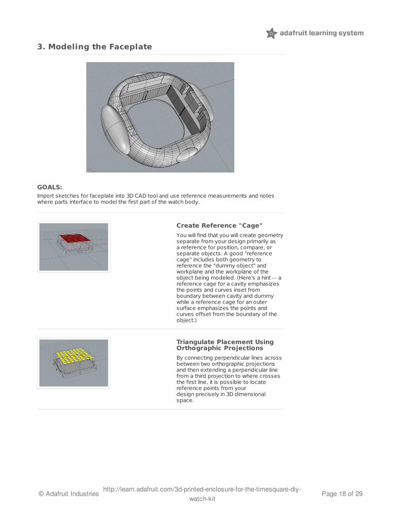
3. Modeling the Faceplate
GOALS:Import sketches for faceplate into 3D CAD tool and use reference measurements and noteswhere parts interface to model the first part of the watch body.
Create Reference "Cage"
You will find that you will create geometryseparate from your design primarily asa reference for position, compare, orseparate objects. A good "referencecage" includes both geometry toreference the "dummy object" andworkplane and the workplane of theobject being modeled. (Here's a hint -- areference cage for a cavity emphasizesthe points and curves inset fromboundary between cavity and dummywhile a reference cage for an outersurface emphasizes the points andcurves offset from the boundary of theobject.)
Triangulate Placement UsingOrthographic Projections
By connecting perpendicular lines acrossbetween two orthographic projectionsand then extending a perpendicular linefrom a third projection to where crossesthe first line, it is possible to locatereference points from yourdesign precisely in 3D dimensionalspace.
© Adafruit Industries http://learn.adafruit.com/3d-printed-enclosure-for-the-timesquare-diy-watch-kit
Page 18 of 29
Use Many Layers (Duplicating,Locking, Hiding)
Get to know the layers in your applicationand develop a practice of duplicating allof the elements that you will use forjoins, surfacing, extruding, booleanoperations, or positioning.
"Reference Layers" are extra layersthat contain only the points, curves, andsurfaces that you use to produce solidparts by combining, lofting, slicing, andboolean operations are of crucial valuelater in the design process as areference for how you created complexshapes. Create separate referencelayers and copy and paste the elementsyou use as tools before runningoperations on them so that you canretrieve them later if something goeswrong and you need to roll back theclock.
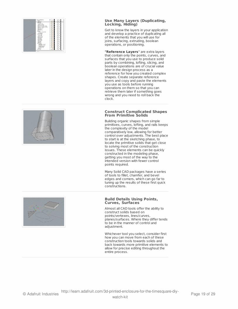
Construct Complicated ShapesFrom Primitive Solids
Building organic shapes from simpleprimitives, curves, lofting, and rails keepsthe complexity of the modelcomparatively low, allowing for bettercontrol over adjustments. The best placeto start is at the sketching phase, tolocate the primitive solids that get closeto solving most of the constructionissues. These elements can be quicklyconstructed in the modeling phase,getting you most of the way to theintended version with fewer controlpoints required.
Many Solid CAD packages have a seriesof tools to fillet, chamfer, and beveledges and corners, which can go far totuning up the results of these first quickconstructions.
Build Details Using Points,Curves, Surfaces
Almost all CAD tools offer the ability toconstruct solids based onpoints/vertexes, lines/curves,planes/surfaces. Where they differ tendsto be in the manner of control andadjustment.
Whichever tool you select, consider firsthow you can move from each of theseconstruction tools towards solids andback towards more primitive elements toallow for precise editing throughout theentire process.
© Adafruit Industries http://learn.adafruit.com/3d-printed-enclosure-for-the-timesquare-diy-watch-kit
Page 19 of 29
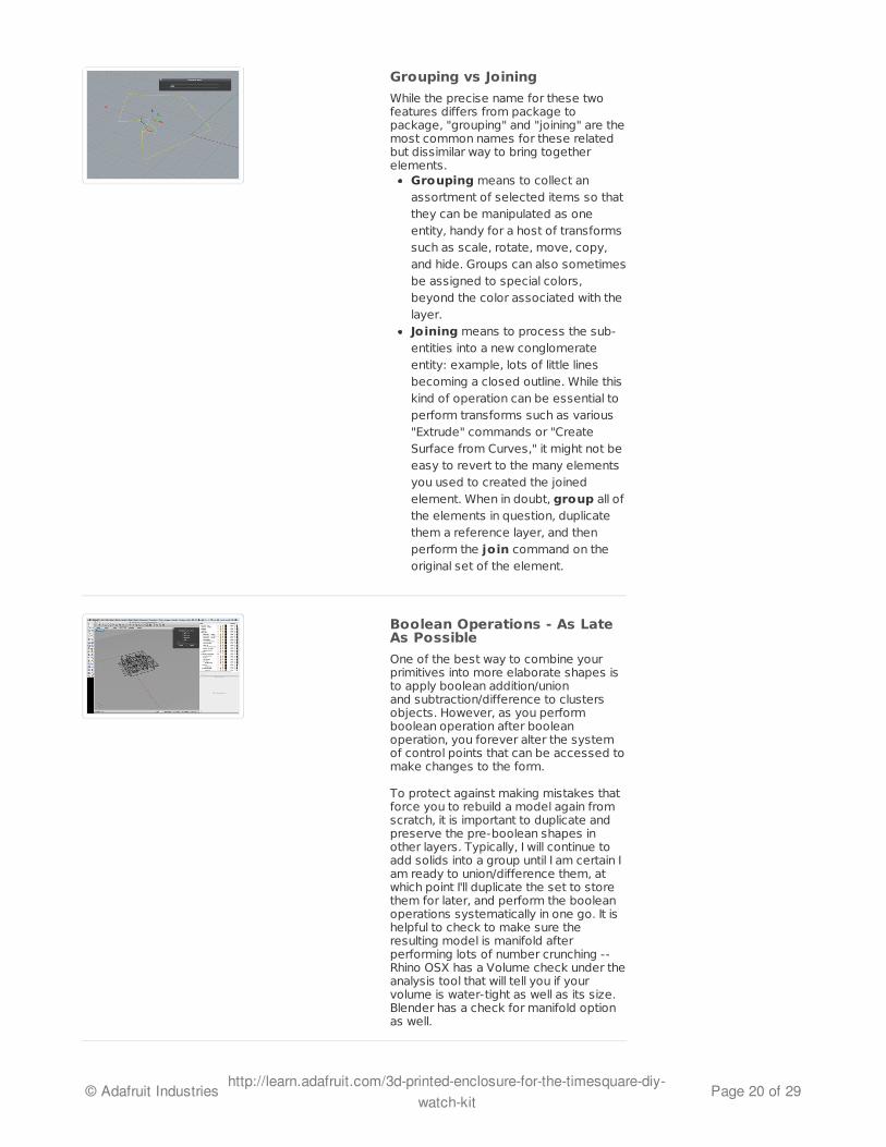
Grouping vs Joining
While the precise name for these twofeatures differs from package topackage, "grouping" and "joining" are themost common names for these relatedbut dissimilar way to bring togetherelements.
Grouping means to collect anassortment of selected items so thatthey can be manipulated as oneentity, handy for a host of transformssuch as scale, rotate, move, copy,and hide. Groups can also sometimesbe assigned to special colors,beyond the color associated with thelayer.Joining means to process the sub-entities into a new conglomerateentity: example, lots of little linesbecoming a closed outline. While thiskind of operation can be essential toperform transforms such as various"Extrude" commands or "CreateSurface from Curves," it might not beeasy to revert to the many elementsyou used to created the joinedelement. When in doubt, group all ofthe elements in question, duplicatethem a reference layer, and thenperform the join command on theoriginal set of the element.
Boolean Operations - As LateAs Possible
One of the best way to combine yourprimitives into more elaborate shapes isto apply boolean addition/unionand subtraction/difference to clustersobjects. However, as you performboolean operation after booleanoperation, you forever alter the systemof control points that can be accessed tomake changes to the form.
To protect against making mistakes thatforce you to rebuild a model again fromscratch, it is important to duplicate andpreserve the pre-boolean shapes inother layers. Typically, I will continue toadd solids into a group until I am certain Iam ready to union/difference them, atwhich point I'll duplicate the set to storethem for later, and perform the booleanoperations systematically in one go. It ishelpful to check to make sure theresulting model is manifold afterperforming lots of number crunching --Rhino OSX has a Volume check under theanalysis tool that will tell you if yourvolume is water-tight as well as its size.Blender has a check for manifold optionas well.
© Adafruit Industries http://learn.adafruit.com/3d-printed-enclosure-for-the-timesquare-diy-watch-kit
Page 20 of 29

Printing Test Parts / InsertionTest
As early as possible, it is important tostart testing your design in the real world.That is, in fact, the best reason to have adesktop 3D printer!
I didn't like the outer contour of thisversion of the watch, but I closed it upquickly so I could print a model to test forfit when inserting the electronics. Idiscovered immediately that my factorfor tolerances was too low -- too tight afit -- and I made changes to both thecavity side and outer shell side to matchthe new measurements.
© Adafruit Industries http://learn.adafruit.com/3d-printed-enclosure-for-the-timesquare-diy-watch-kit
Page 21 of 29

4. Adding Buttons
GOALS:Work with Faceplate test prints to determine placement of buttons and how they shouldinterface with the enclosed electronics.
Trapped Button Caps
In order to offer access to the buttonssoldered to the TIMESQUARE PCB, Idecided to build printed "caps" to extendthe button press beyond the watch body.To keep the mechanical complexity low, Iadded a base to the button that wouldprevent it from falling out of the narrowbutton cavity, and scaled it down tocompensate for more than the usualtolerance factor so that the button capwould sit in its cavity loose enough tomove, but not enough to rattle.
Previous attempts to construct thebuttons were too fragile, both in terms ofthe width of the shaft (shifting from3.5mm to 5mm) and infill density (rotatedthe direction of infill and printed at 100%infill). I came to the result that workedthrough trial and error, taking notes eachprint as to the ideal height of the shaft,width for base, and shape of the groovesaround the base to prevent rattling.
Wireframe Routing Tip
One challenge for the base of the buttonwas how to make sure thebutton functions well when pressed fromany angle without either hitting the edgeof the PCB (preventing the printed buttoncap from hitting the button on the board)or rattling.
To help me solve this problem, Iactivated the layer that had the dummycutting tool (ie larger than the printabledummy part) and to start the button cageand used the button that I had modeledon the dummy to help me find an angle
© Adafruit Industries http://learn.adafruit.com/3d-printed-enclosure-for-the-timesquare-diy-watch-kit
Page 22 of 29
satisfying my conditions.
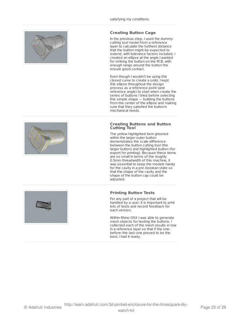
Creating Button Cage
In the previous step, I used the dummycutting tool model from a referencelayer to calculate the furthest distancethat the button might be expected toextend, with tolerance factors included. Icreated an ellipse at the angle I wantedfor striking the button on the PCB, withenough range around the button theensure good contact.
Even though I wouldn't be using thisclosed curve to create a solid, I keptthis ellipse throughout the designprocess as a reference point (andreference angle) to start when create theseries of buttons I tried before selectingthis simple shape -- building the buttonsfrom the center of the ellipse and makingsure that they satisfied the button'smechanical needs.
Creating Buttons and ButtonCutting Tool
The yellow highlighted item ghostedwithin the larger outer buttondemonstrates the scale differencebetween the button cutting tool (thelarger button) and highlighted button (forexport for printing). Because these itemsare so small in terms of the roughly0.5mm threadwidth of this machine, itwas essential to keep the models handyfor the cavity in a pre-boolean state sothat the shape of the cavity and theshape of the button cap could beadjusted.
Printing Button Tests
For any part of a project that will behandled by a user, it is important to printlots of tests and record feedback foreach version.
Within Rhino OSX I was able to generatemesh objects for testing the buttons. Icollected each of the mesh results in rowin a reference layer so that if the one-before-the-last-one proved to be thebest, I had it ready.
© Adafruit Industries http://learn.adafruit.com/3d-printed-enclosure-for-the-timesquare-diy-watch-kit
Page 23 of 29
5. Preparing for Wrist Straps
5. Preparing for Wrist Straps (http://adafru.it/aW3)Create and implement a cutting tool for routing wrist straps / pocket watch fob. Create snap-fitstrap bar for easier handling.
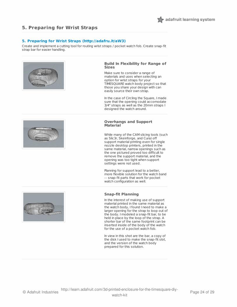
Build In Flexibility for Range ofSizes
Make sure to consider a range ofmaterials and uses when selecting anoption for wrist straps for yourTIMESQUARE watch body project so thatthose you share your design with caneasily source their own strap.
In the case of Circling the Square, I madesure that the opening could accomodate3/4" straps as well as the 20mm straps Idesigned the watch around.
Overhangs and SupportMaterial
While many of the CAM slicing tools (suchas Slic3r, Skeinforge, and Cura) offsupport material printing even for singlenozzle desktop printers, printed in thesame material, narrow openings such asthe one pictured proved too difficult toremove the support material, and theopening was too tight when supportsettings were not used.
Planning for support lead to a better,more flexible solution for the watch band-- snap-fit parts that work for pocketwatch configuration as well.
Snap-fit Planning
In the interest of making use of supportmaterial printed in the same material asthe watch body, I found I need to make alarger opening for the strap to loop out ofthe body. I modeled a snap-fit bar, to beheld in place by the loop of the strap. Ashorter bar of the same footprint can beinserted inside of the body of the watchfor the use of a pocket watch fob.
In view in this shot are the bar, a copy ofthe disk I used to make the snap-fit slot,and the version of the watch bodyprepared for this solution.
© Adafruit Industries http://learn.adafruit.com/3d-printed-enclosure-for-the-timesquare-diy-watch-kit
Page 24 of 29
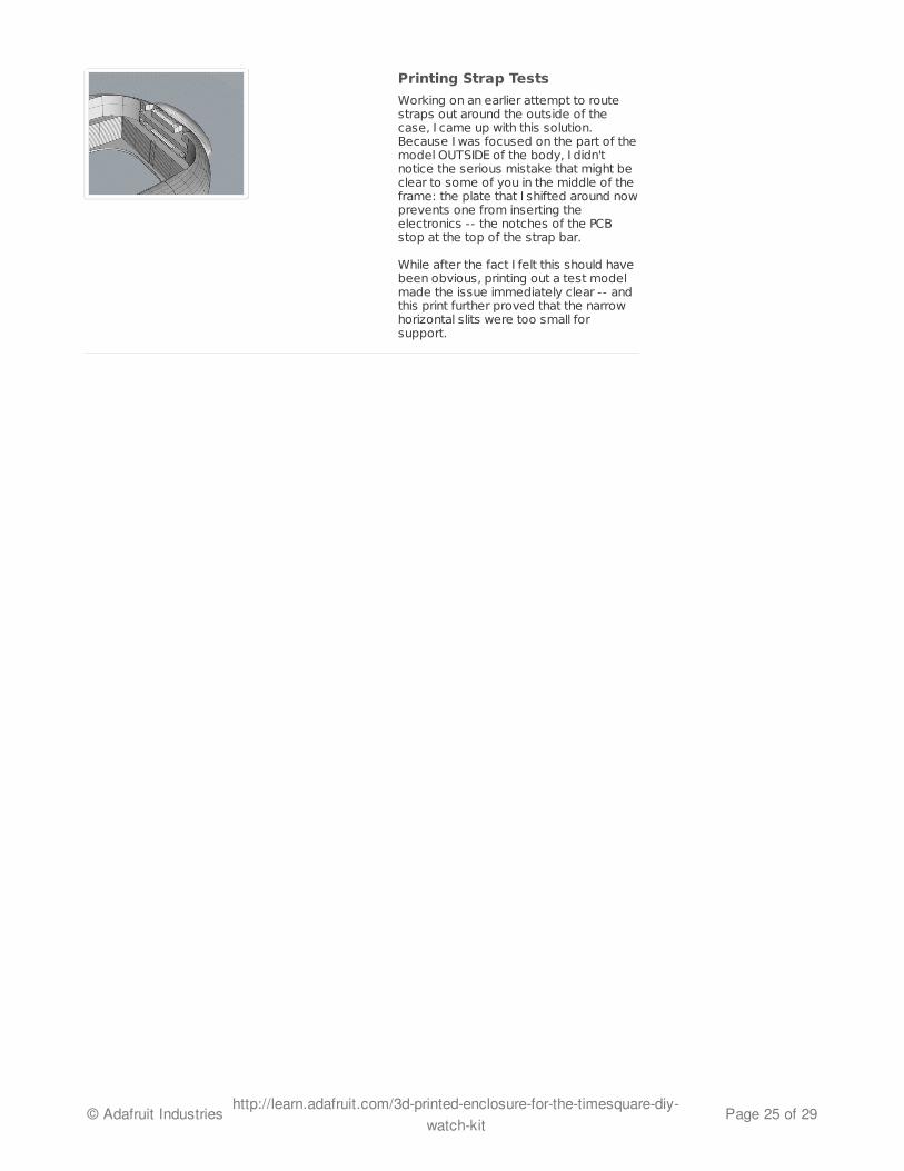
Printing Strap Tests
Working on an earlier attempt to routestraps out around the outside of thecase, I came up with this solution.Because I was focused on the part of themodel OUTSIDE of the body, I didn'tnotice the serious mistake that might beclear to some of you in the middle of theframe: the plate that I shifted around nowprevents one from inserting theelectronics -- the notches of the PCBstop at the top of the strap bar.
While after the fact I felt this should havebeen obvious, printing out a test modelmade the issue immediately clear -- andthis print further proved that the narrowhorizontal slits were too small forsupport.
© Adafruit Industries http://learn.adafruit.com/3d-printed-enclosure-for-the-timesquare-diy-watch-kit
Page 25 of 29
6. Modeling the Backplate
GOALSModel the backplate to closeup back of watch body, to insulate the electronics, and toaccomodate wrist straps.
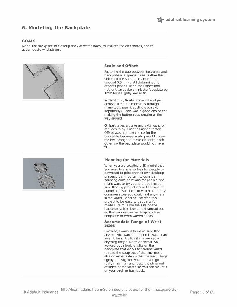
Scale and Offset
Factoring the gap between faceplate andbackplate is a special case. Rather thanselecting the same tolerance factor(around 0.5mm) that I determined forother fit places, used the Offset tool(rather than scale) shrink the faceplate by1mm for a slightly looser fit.
In CAD tools, Scale shrinks the objectacross all three dimensions (thoughmany tools permit scaling each axisseparately). Scale was a good choice formaking the button caps smaller all theway around.
Offset takes a curve and extends it (orreduces it) by a user assigned factor.Offset was a better choice for thebackplate because scaling would causethe two prongs to move closer to eachother, so the backplate would not havefit.
Planning for Materials
When you are creating a 3D model thatyou want to share as files for people todownload to print on their own desktopprinters, it is important to considersourcing considerations for people whomight want to try your project. I madesure that my project would fit straps of20mm and 3/4", both of which are prettycommon sizes you could find anywherein the world. Because I wanted thisproject to be easy to get parts for, Imade sure to leave the slits on thebackplate a little looser and spread outso that people can try things such asneoprene or even woven bands.
Accomodate Range of WristSizes
Likewise, I wanted to make sure thatanyone who wants to print this watch canwear it, hang it, stick it in a pocket --anything they'd like to do with it. So Iworked out a logic of slits on thebackplate that works for narrow wrists(thread the strap out of the innermostslits on either side so that the watch hugstightly to a slighter wrist) or even goreally maximum and route the strap outof sides of the watch so you can mount iton your thigh or backpack.
© Adafruit Industries http://learn.adafruit.com/3d-printed-enclosure-for-the-timesquare-diy-watch-kit
Page 26 of 29
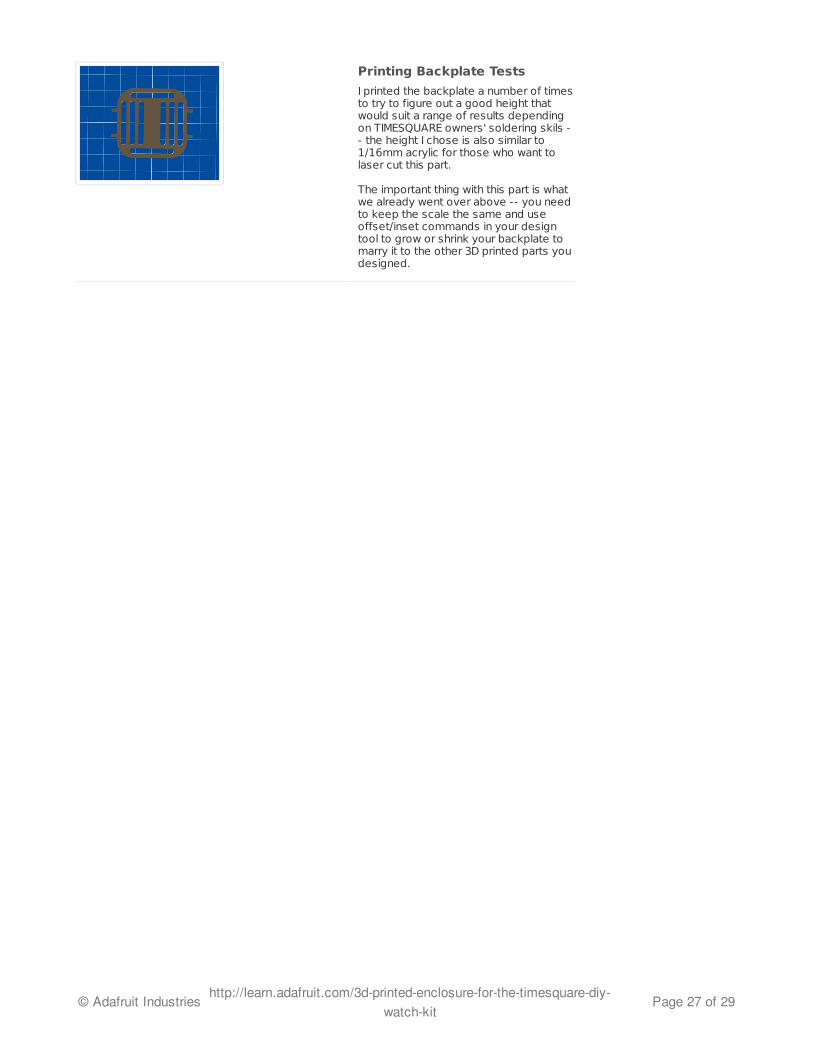
Printing Backplate Tests
I printed the backplate a number of timesto try to figure out a good height thatwould suit a range of results dependingon TIMESQUARE owners' soldering skils -- the height I chose is also similar to1/16mm acrylic for those who want tolaser cut this part.
The important thing with this part is whatwe already went over above -- you needto keep the scale the same and useoffset/inset commands in your designtool to grow or shrink your backplate tomarry it to the other 3D printed parts youdesigned.
© Adafruit Industries http://learn.adafruit.com/3d-printed-enclosure-for-the-timesquare-diy-watch-kit
Page 27 of 29
Printing and Proofing Your Models
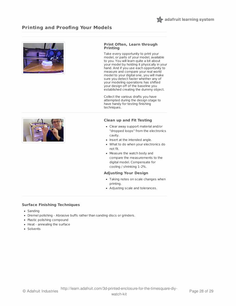
Print Often, Learn throughPrinting
Take every opportunity to print yourmodel, or parts of your model, availableto you. You will learn quite a bit aboutyour model by holding it physically in yourhand. And if you use each opportunity tomeasure and compare your real worldmodel to your digital one, you will makesure you detect faster whether any ofyour modeling operations has shiftedyour design off of the baseline youestablished creating the dummy object.
Collect the various drafts you haveattempted during the design stage tohave handy for testing finishingtechniques.
Clean up and Fit Testing
Clear away support material and/or"dropped loops" from the electronicscavity.Insert at the intended angle.What to do when your electronics donot fit.Measure the watch body andcompare the measurements to thedigital model. Compensate forcooling / shrinking 1-2%.
Adjusting Your Design
Taking notes on scale changes whenprinting.Adjusting scale and tolerances.
Surface Finishing Techniques
SandingDremel polishing - Abrasive buffs rather than sanding discs or grinders.Plastic polishing compoundHeat - annealing the surfaceSolvents
© Adafruit Industries http://learn.adafruit.com/3d-printed-enclosure-for-the-timesquare-diy-watch-kit
Page 28 of 29
Sharing Your Design
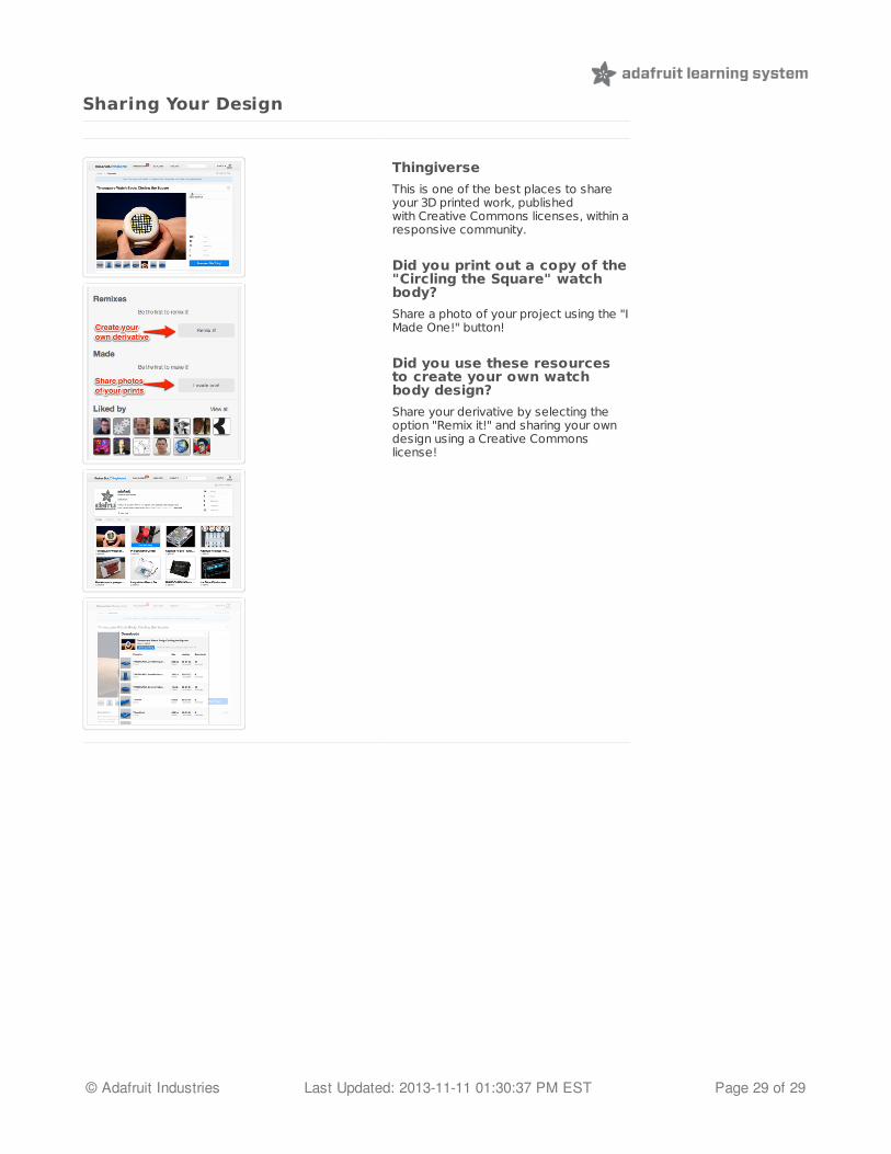
Thingiverse
This is one of the best places to shareyour 3D printed work, publishedwith Creative Commons licenses, within aresponsive community.
Did you print out a copy of the"Circling the Square" watchbody?
Share a photo of your project using the "IMade One!" button!
Did you use these resourcesto create your own watchbody design?
Share your derivative by selecting theoption "Remix it!" and sharing your owndesign using a Creative Commonslicense!
© Adafruit Industries Last Updated: 2013-11-11 01:30:37 PM EST Page 29 of 29