Embed Size (px)
DESCRIPTION
test
Citation preview

Power and productivity
for a better worldTM
S800 I/OFieldbus Communication Interface for PROFIBUS DP/DPV1


S800 I/OFieldbus Communication Interface for PROFIBUS DP/DPV1

NOTICEThis document contains information about one or more ABB products and may include adescription of or a reference to one or more standards that may be generally relevant tothe ABB products. The presence of any such description of a standard or reference to astandard is not a representation that all of the ABB products referenced in this documentsupport all of the features of the described or referenced standard. In order to determinethe specific features supported by a particular ABB product, the reader should consult theproduct specifications for the particular ABB product.
ABB may have one or more patents or pending patent applications protecting the intel-lectual property in the ABB products described in this document.
The information in this document is subject to change without notice and should not beconstrued as a commitment by ABB. ABB assumes no responsibility for any errors thatmay appear in this document.
In no event shall ABB be liable for direct, indirect, special, incidental or consequentialdamages of any nature or kind arising from the use of this document, nor shall ABB beliable for incidental or consequential damages arising from use of any software or hard-ware described in this document.
This document and parts thereof must not be reproduced or copied without written per-mission from ABB, and the contents thereof must not be imparted to a third party nor usedfor any unauthorized purpose.
The software or hardware described in this document is furnished under a license andmay be used, copied, or disclosed only in accordance with the terms of such license. Thisproduct meets the requirements specified in EMC Directive 2004/108/EEC and in LowVoltage Directive 2006/95/EEC.
TRADEMARKSAll rights to copyrights, registered trademarks, and trademarks reside with their respec-tive owners.
Copyright © 2003-2010 by ABB. All rights reserved.
Release: June 2010Document number: 3BSE020926-510

3BSE020926-510 5
TABLE OF CONTENTS
About This BookGeneral ............................................................................................................................11
Document Conventions ...................................................................................................11
Warning, Caution, Information, and Tip Icons................................................................11
Terminology.....................................................................................................................12
Related Documentation ...................................................................................................14
Section 1 - IntroductionProduct Overview ............................................................................................................16
Product Scope.......................................................................................................16
Section 2 - Installation
Section 3 - ConfigurationCI801 FCI ........................................................................................................................31
Address Switches .................................................................................................31
PROFIBUS Connection .......................................................................................32
Power Supply Connections ..................................................................................34
CI830 FCI ........................................................................................................................35
Address Switches .................................................................................................35
PROFIBUS-DP Connections ...............................................................................35
Power Supply Connections ..................................................................................37
CI840 FCI ........................................................................................................................38
Address Switches .................................................................................................38
PROFIBUS Connections......................................................................................39
Power Supply Connections ..................................................................................41
Table of Contents
6 3BSE020926-510
Configuration and Performance ...................................................................................... 42
CI801 Configuration Rules .................................................................................. 42
CI830 Configuration Rules .................................................................................. 47
CI840 Configuration Rules .................................................................................. 51
Supported I/O Modules and Drives via PROFIBUS and CI801.......................... 56
Supported I/O Modules and Drives via PROFIBUS and CI830.......................... 57
Supported I/O Modules via PROFIBUS and CI840 ............................................ 58
Data Scanning ...................................................................................................... 58
Section 4 - OperationOperating Overview ........................................................................................................ 63
Getting Started ................................................................................................................ 63
Functional Description......................................................................................... 63
I/O Module Functionality .................................................................................... 67
Section 5 - MaintenancePreventive Maintenance .................................................................................................. 73
Hardware Indicators ........................................................................................................ 73
CI801 FCI Module LEDs .................................................................................... 73
CI830 FCI Module LEDs .................................................................................... 75
CI840 FCI Module LEDs .................................................................................... 77
Error Messages................................................................................................................ 78
Fault Finding and Repair................................................................................................. 79
Communication Module Replacement ................................................................ 79
Application Memory Reset .................................................................................. 83
CI801 Firmware version ...................................................................................... 83
CI840 Firmware version ...................................................................................... 84
Backup/Restore Procedures ............................................................................................ 84
Load the CI801 Software Upgrade ...................................................................... 84
Load the CI830 Software Upgrade ...................................................................... 87
Load the CI840 Software Upgrade ...................................................................... 89
Appendix A - Specifications
Table of Contents
3BSE020926-510 7
3BSE020926-510 7
CI801 Fieldbus Communications Interface (FCI) ...........................................................95
Features .............................................................................................................95
Description ...........................................................................................................95
Technical Data......................................................................................................96
Dimensions...........................................................................................................98
Connections..........................................................................................................98
Block Diagram CI801 ........................................................................................100
CI830 Fieldbus Communications Interface (FCI) .........................................................101
Features ...........................................................................................................101
Description .........................................................................................................101
Technical Data....................................................................................................102
Dimensions.........................................................................................................104
Connections........................................................................................................104
Block Diagram CI830 ........................................................................................107
CI840 Fieldbus Communications Interface (FCI) .........................................................108
Features ...........................................................................................................108
Description .........................................................................................................108
Technical Data....................................................................................................111
Connections........................................................................................................112
Block Diagram CI840, single ModuleBus .........................................................113
Block Diagram CI840, dual ModuleBus............................................................114
TU846 Redundant MTU for CI840, dual ModuleBus ..................................................115
Features ...........................................................................................................115
Description .........................................................................................................115
Technical Data....................................................................................................116
Dimensions.........................................................................................................117
Connections ......................................................................................................118
Block Diagram TU846.......................................................................................120
TU847 Redundant MTU for CI840, single ModuleBus................................................121
Features ...........................................................................................................121
Description .........................................................................................................121
Technical Data....................................................................................................122
Table of Contents
8 3BSE020926-510
Dimensions ........................................................................................................ 123
Connections ..................................................................................................... 124
Block Diagram TU847....................................................................................... 126
INDEX

3BSE020926-510 9
Safety Summary
Electrostatic Sensitive DeviceDevices labeled with this symbol require special handling precautions as described in the installation section.
GENERAL WARNINGS
Equipment EnvironmentAll components, whether in transportation, operation or storage, must be in a noncorrosive environment.
Electrical Shock Hazard During MaintenanceDisconnect power or take precautions to insure that contact with ener-gized parts is avoided when servicing.
SPECIFIC CAUTIONS
Page-81: If the last CI801 on a PROFIBUS segment supplies an active termination in the cable connector, disconnection of the power supply or the PROFIBUS cable to CI801 can not be done without disrupting the bus.
Page-82: If the last CI830 on a PROFIBUS segment supplies an active termination in the cable connector, disconnection of the power supply or the PROFIBUS cable to CI830 can not be done without disrupting the bus.
Page-82: If the last CI840 on a PROFIBUS segment supplies an active termination in the cable connector, disconnection of the power supply or the PROFIBUS cable to CI840 can not be done without disrupting the bus.

10 3BSE020926-510
Safety Summary

3BSE020926-510 11
About This Book
GeneralThis book provides a description of the S800 field communication using PROFIBUS-DP/DPV1. It provides instructions for site planning and installation, start-up and shutdown procedures, and information regarding capacity and performance. This book is not intended to be the sole source of instruction for the S800 I/O system.
Document ConventionsMicrosoft Windows conventions are normally used for the standard presentation of material when entering text, key sequences, prompts, messages, menu items, screen elements, etc.
Warning, Caution, Information, and Tip IconsThis publication includes Warning, Caution, and Information where appropriate to point out safety related or other important information. It also includes Tip to point out useful hints to the reader. The corresponding symbols should be interpreted as follows:
Electrical warning icon indicates the presence of a hazard which could result in electrical shock.
Warning icon indicates the presence of a hazard which could result in personal injury.

Terminology About This Book
12 3BSE020926-510
Although Warning hazards are related to personal injury, and Caution hazards are associated with equipment or property damage, it should be understood that operation of damaged equipment could, under certain operational conditions, result in degraded process performance leading to personal injury or death. Therefore, fully comply with all Warning and Caution notices.
TerminologyA complete and comprehensive list of Terms is included in the IndustrialIT Extended Automation System 800xA, Engineering Concepts instruction (3BDS100972*). The listing included in Engineering Concepts includes terms and definitions as they that apply to the 800xA system where the usage is different from commonly accepted industry standard definitions and definitions given in standard dictionaries such as Webster’s Dictionary of Computer Terms.
Caution icon indicates important information or warning related to the concept discussed in the text. It might indicate the presence of a hazard which could result in corruption of software or damage to equipment/property.
Information icon alerts the reader to pertinent facts and conditions.
Tip icon indicates advice on, for example, how to design your project or how to use a certain function
Term Description
Base cluster Consists of single or redundant FCIs plus I/O modules connected directly to the FCI.
FCI The Fieldbus Communication Interface (FCI) device contains the interface to the fieldbus PROFIBUS-DP/DPV1, ModuleBus interface and power regulators. The FCI module can manage 24 I/O devices (up to 12 directly and to the others in 1 to 7 I/O clusters).
HCIR Hot Configuration In Run, possibility to change configuration in a running system.

About This Book Terminology
3BSE020926-510 13
I/O cluster An extension of the I/O Station’s ModuleBus connected to the FCI by fiber optic connections. Up to 12 I/O devices per cluster.
I/O device A complete I/O device consists of one MTU and one I/O module.
I/O module Is an active, electronic and signal conditioning unit. Can be a part of an I/O device or a S800L I/O module.
I/O station An I/O station consists of a base cluster with single or redundant FCI(s), 1-7 I/O clusters and up to 24 I/O devices.
I.S. Intrinsic Safety is a protection technique to prevent explosion in hazardous areas of a process plant.
ModuleBus Is an incremental, electrical or optical, bus for interconnection of I/O devices.
(ModuleBus) Extension cable
Is used when extending the electrical ModuleBus (within the max. 2.5 meters 8.2”).
MTU The Module Termination Unit is a passive base unit containing process terminals and a part of the ModuleBus.
OSP Outputs Set as Predetermined. A user configurable action on an output module when communications is lost to the FCI or Controller.
PROFIBUS-DP PROFIBUS-DP is a fieldbus standard.
PROFIBUS-DPV1 PROFIBUS-DPV1 is a fieldbus standard.
PROFIBUS Stands for both PROFIBUS-DP and PROFIBUS-DPV1.
TC Thermocoupler
Term Description

Related Documentation About This Book
14 3BSE020926-510
Related DocumentationThe following is a listing of documentation related to Fieldbus Communication Interface for PROFIBUS-DP/DPV1.
Table 1. Related Documentation
Title Description
S800 I/O Getting Started Describes the general installation and configuration information for the S800 I/O system.
S800 I/O Modules and Termination Units
Describes the I/O modules and termination units in the S800 I/O system.
S800 I/O Modules and Termination Units with Intrinsic Safety Interface
Describes the I/O modules and termination units with I.S. interface in the S800 I/O system.
S800 I/O PROFIBUS FCI Memory Maps for CI801
Describes the memory mapping on PROFIBUS-DPV1 in CI801 for the S800 I/O system.
S800 I/O PROFIBUS FCI Memory Maps for CI830
Describes the memory mapping on PROFIBUS-DP in CI830 for the S800 I/O system.
S800 I/O PROFIBUS FCI Memory Maps for CI840
Describes the memory mapping on PROFIBUS-DPV1 in CI840 for the S800 I/O system.

3BSE020926-510 15
Section 1 Introduction
The S800 I/O is distributed modular I/O which communicates with numerous controllers over a Advant Fieldbus 100 (AF100), PROFIBUS-DP/DPV1 or directly. The S800 I/O provides easy installation of the I/O modules and process cabling. It is highly modularized and flexible so that I/O modules can be combined to suit many applications. The S800 I/O can be mounted in many configurations to fit most requirements.
Figure 1. S800 I/O Fieldbus Communication Interface with an I/O Module on Compact and Extended MTUs

Product Overview Section 1 Introduction
16 3BSE020926-510
Product OverviewThe S800 I/O provides easy installation of the I/O modules and process cabling. It is highly modularized and flexible so that the I/O modules can be combined to suit many applications. The S800 I/O modules and a Fieldbus Communication Interface (FCI) are combined to form an I/O Station.
In general all S800 units are G3 compliant. G3 compliant modules withstand more severe environmental conditions according to ISA-S71.04 .The following S800 units are G2 compliant - SD821, SD822, SD823, SD831, SD832, SD833, SD834, SS822, SS832, TB811 and CI830. G3 compliant versions of SD822 and SS822 are available (refer to SD822Z and SS822Z).
The standards referred to are followed in applicable parts which are described in this manual.
For more overview information refer S800 I/O Getting Started (3BSE020923*).
Product Scope
CI801 Fieldbus Communications Interface (FCI)
The CI801 Fieldbus Communication Interface (FCI) module is a configurable communication interface which performs operations such as signal processing, gathering of various supervision information, OSP handling and configuration of I/O modules. The FCI connects to a controller by way of the PROFIBUS-DPV1 fieldbus.
The FCI has one PROFIBUS-DPV1 interface and uses a PROFIBUS-DP cable with a total length of up to 1200 meters (1312 yards). Up to 32 stations can be configured on one segment. The station address sets by rotary switches that select the address on the fieldbus in the range of 01 to 99.
The FCI modules are DIN rail mounted and have connections for input power, PROFIBUS and two rotary switches for station address selection.
An I/O Station can consist of the FCI modules, ModuleBus Modems and the I/O modules. The FCI is the bus-master on the S800 I/O ModuleBus and communicates with the S800 I/O modules. It is a pure “slave station” on PROFIBUS-DPV1 which is controlled by a master station.

Section 1 Introduction Product Scope
3BSE020926-510 17
I/O Station modules are mounted on DIN rails and are connected by the ModuleBus. Figure 2 shows the FCI modules connected to the Optical ModuleBus Port TB842.

Product Scope Section 1 Introduction
18 3BSE020926-510
The FCI communicates with the PROFIBUS Master, ModuleBus Modems and the I/O modules. The FCI handles the I/O-modules operations such as read and write data, read status and configuration of modules and channels. The FCI has a connection to the TB842 Optical ModuleBus Port mounted on a TB806 to the left, see Figure 2.
Figure 2. CI801 FCI Module and TB842 Optical ModuleBus Port
1
Power Supply
AddressSwitch #1
AddressSwitch #2PROFIBUS
Connector
LED StatusIndicators
ModuleBusInterfaceConnector
TB806TB842

Section 1 Introduction Product Scope
3BSE020926-510 19
The FCI provides 24 V d.c. (from the source) and an isolated 5 V d.c power to the base cluster’s I/O modules (12 maximum) by way of the ModuleBus connections. One power source 24 V d.c. can be connected to the power terminals (L+ & L-).
The power source is supervised by the POWER OK status LED.
The size, type and direction of data to be transferred on the PROFIBUS-DP bus depends on and is determined by the I/O module type. The FCI can be configured to send or transmit dynamic data over the PROFIBUS-DP with cycle times in the interval from 1 ms.
CI830 Fieldbus Communications Interface (FCI)
The CI830 Fieldbus Communication Interface (FCI) module is a configurable communication interface for single configurations which performs operations such as signal processing, gathering of various supervision information, OSP handling and configuration of I/O modules. The FCI connects to a controller by way of the PROFIBUS-DP fieldbus.
The FCI has one PROFIBUS-DP interface and uses a PROFIBUS-DP cable with a total length of up to 1200 meters (1312 yards). Up to 32 stations can be configured on one segment. The FCI has two rotary switches that select its address on the fieldbus in the range of 01 to 79.
An I/O Station can consist of the FCI module, ModuleBus Modems and the I/O modules. The FCI is the bus-master on the S800 I/O ModuleBus and communicates with the S800 I/O modules. It is a pure “slave station” on PROFIBUS-DP which is controlled by a master station.
Product Scope Section 1 Introduction
20 3BSE020926-510
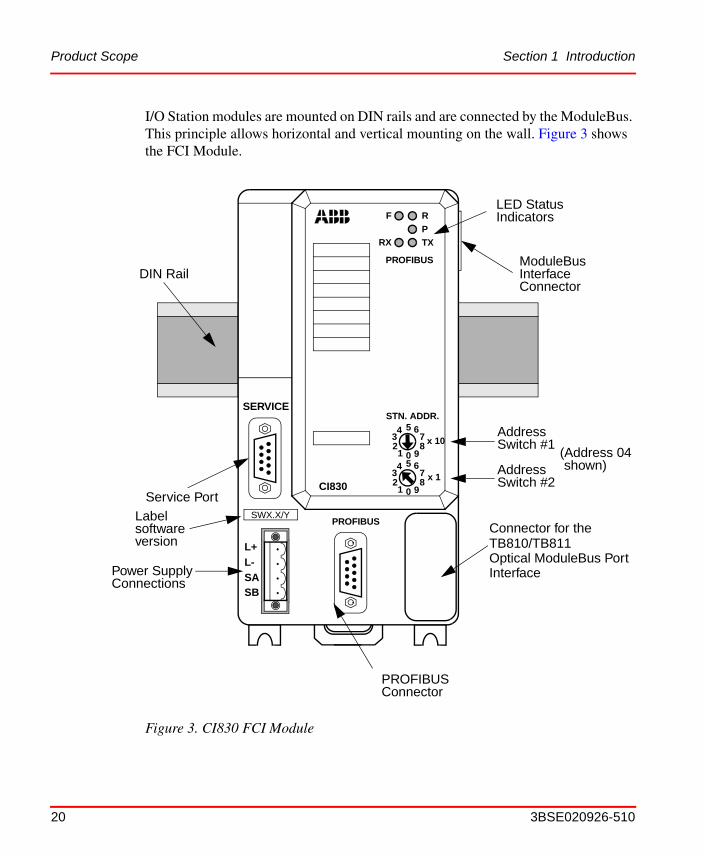
I/O Station modules are mounted on DIN rails and are connected by the ModuleBus. This principle allows horizontal and vertical mounting on the wall. Figure 3 shows the FCI Module.
Figure 3. CI830 FCI Module
STN. ADDR.
Tx
Rx
F R
TXRXP
SERVICE
CI830
012
9
75
38
4 6
012
9
75
38
4 6
x 10
x 1
PROFIBUS
AddressSwitch #1
AddressSwitch #2
Power SupplyConnections
PROFIBUS
LED Status Indicators
DIN RailModuleBusInterface Connector
Connector
Service Port
(Address 04shown)
Tx RxSWX.X/YLabel
softwareversion
PROFIBUS
L+L-SASB
Connector for the
Optical ModuleBus Port Interface
TB810/TB811
Section 1 Introduction Product Scope
3BSE020926-510 21
The FCI communicates with the PROFIBUS Master, ModuleBus Modems and the I/O modules. The FCI handles the I/O-modules operations such as read and write data, read status and configuration of modules and channels. The FCI has a connector for the TB810/TB811 Optical ModuleBus Port.
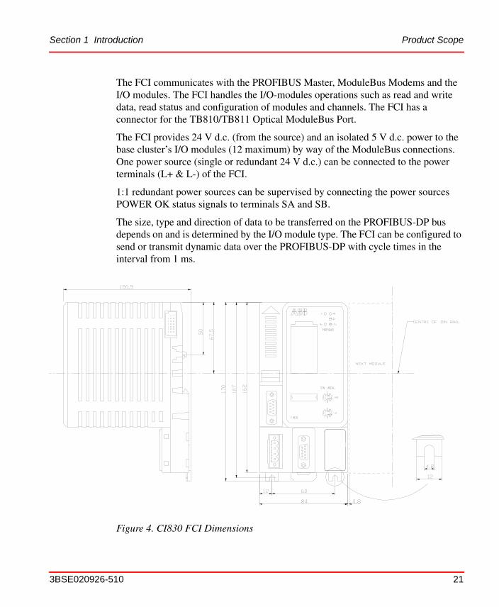
The FCI provides 24 V d.c. (from the source) and an isolated 5 V d.c. power to the base cluster’s I/O modules (12 maximum) by way of the ModuleBus connections. One power source (single or redundant 24 V d.c.) can be connected to the power terminals (L+ & L-) of the FCI.
1:1 redundant power sources can be supervised by connecting the power sources POWER OK status signals to terminals SA and SB.
The size, type and direction of data to be transferred on the PROFIBUS-DP bus depends on and is determined by the I/O module type. The FCI can be configured to send or transmit dynamic data over the PROFIBUS-DP with cycle times in the interval from 1 ms.
Figure 4. CI830 FCI Dimensions
Product Scope Section 1 Introduction
22 3BSE020926-510
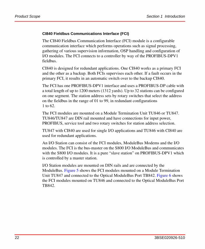
CI840 Fieldbus Communications Interface (FCI)
The CI840 Fieldbus Communication Interface (FCI) module is a configurable communication interface which performs operations such as signal processing, gathering of various supervision information, OSP handling and configuration of I/O modules. The FCI connects to a controller by way of the PROFIBUS-DPV1 fieldbus.
CI840 is designed for redundant applications. One CI840 works as a primary FCI and the other as a backup. Both FCIs supervises each other. If a fault occurs in the primary FCI, it results in an automatic switch over to the backup CI840.
The FCI has one PROFIBUS-DPV1 interface and uses a PROFIBUS-DP cable with a total length of up to 1200 meters (1312 yards). Up to 32 stations can be configured on one segment. The station address sets by rotary switches that select the address on the fieldbus in the range of 01 to 99, in redundant configurations 1 to 62.
The FCI modules are mounted on a Module Termination Unit TU846 or TU847. TU846/TU847 are DIN rail mounted and have connections for input power, PROFIBUS, service tool and two rotary switches for station address selection.
TU847 with CI840 are used for single I/O applications and TU846 with CI840 are used for redundant applications.
An I/O Station can consist of the FCI modules, ModuleBus Modems and the I/O modules. The FCI is the bus-master on the S800 I/O ModuleBus and communicates with the S800 I/O modules. It is a pure “slave station” on PROFIBUS-DPV1 which is controlled by a master station.
I/O Station modules are mounted on DIN rails and are connected by the ModuleBus. Figure 5 shows the FCI modules mounted on a Module Termination Unit TU847 and connected to the Optical ModuleBus Port TB842. Figure 6 shows the FCI modules mounted on TU846 and connected to the Optical ModuleBus Port TB842.

Section 1 Introduction Product Scope
3BSE020926-510 23
Figure 5. CI840 FCI Module, TU847 Termination Unit and TB842 Optical ModuleBus Port
AddressSwitch #1
Address
Power SupplyConnections
PROFIBUS
LED Status Indicators
ModuleBusInterface Connector
Connector
(Address 66shown)
CI840 CI840 Switch #2
ServicePorts
1
TB806
TB842
FR
PRIM
PRx/Tx
DUAL
FR
PRIM
PRx/Tx
DUAL

Product Scope Section 1 Introduction
24 3BSE020926-510
Figure 6. CI840 FCI Module, TU846 Termination Unit and TB842 Optical ModuleBus Port

Section 1 Introduction Product Scope
3BSE020926-510 25
The FCI communicates with the PROFIBUS Master, ModuleBus Modems and the I/O modules. The FCI handles the I/O-modules operations such as read and write data, read status and configuration of modules and channels. The FCI has a connection to the TB842 Optical ModuleBus Port.
The FCI provides 24 V d.c. (from the source) and an isolated 5 V d.c. power to the base cluster’s I/O modules (12 maximum or 6 pairs) by way of the ModuleBus connections. One power source (single or redundant 24 V d.c.) can be connected to the power terminals (L+ & L-) of the MTU.
1:1 redundant power sources can be supervised by connecting the power sources POWER OK status signals to terminals SA and SB.
The size, type and direction of data to be transferred on the PROFIBUS-DPV1 bus depends on and is determined by the I/O module type. The FCI can be configured to send or transmit dynamic data over the PROFIBUS-DPV1 with cycle times in the interval from 1 ms.

Product Scope Section 1 Introduction
26 3BSE020926-510
For CI840 FCI and TU846/TU847 dimensions, see Figure 7 and Figure 8.
Figure 7. TU847 Dimensions (Same Dimensions for TU846)

Section 1 Introduction Product Scope
3BSE020926-510 27
Figure 8. CI840 FCI and TU847 Terminal Unit Dimensions (Same Dimensions for TU846)
124 mm (4.88”)
128 mm
47 mm
162,9 mm
(1.85”)
(5.04”)
(6.41”) 186,5 mm(7.34”)

Product Scope Section 1 Introduction
28 3BSE020926-510

3BSE020926-510 29
Section 2 Installation
Refer S800 I/O Getting Started (3BSE020923*).
For PROFIBUS, see PROFIBUS DP Wiring and Installation (3BDS009029*).

Section 2 Installation
30 3BSE020926-510

3BSE020926-510 31
Section 3 Configuration
CI801 FCIThe FCI needs to be connected to the PROFIBUS-DPV1 and have an address selected. It is also connected to a 24 V d.c. power source to provide power to the I/O Station. Also refer to Configuration and Performance on page 42 for information on how to estimate the fieldbus and power loading of each I/O station configuration.
Address Switches
The CI801 is equipped with two rotary switches used as station address selectors for PROFIBUS connection. The station address can be set in the range of 01 to 99. There can be up to 32 stations per PROFIBUS-DPV1 segment. Figure 9 shows the front panel of the CI801.
Figure 9. CI801 Front Panel
AddressSwitch #1
AddressSwitch #2

PROFIBUS Connection Section 3 Configuration
32 3BSE020926-510
PROFIBUS Connection
The FCI connects to the PROFIBUS through the 9 pin D-way connector on the front. This allows the FCI (if not the last one at the PROFIBUS segment) to be removed from the PROFIBUS without disconnecting the other nodes of the fieldbus.
If CI801 is the last module at a PROFIBUS segment and supplies an active termination in the cable connector, disconnection of the power supply or the PROFIBUS cable from CI801 can not be done without disrupting the bus.
See Figure 10 for CI801 connection details.
Figure 10. CI801 FCI PROFIBUS Terminal Connections
Profibus Cable

Section 3 Configuration PROFIBUS Connection
3BSE020926-510 33
Table 2 shows the fieldbus connection assignments.
Table 2. FCI PROFIBUS Connections
Pin Designation Description
1 Shield Shield/protective ground
2 - Not used
3 RxD/TxD-P Receive/Transmit data - plus
4 RTS Direction control (optional)
5 DGND Data ground
6 VP Supply voltage for the terminating resistors
7 - Not used
8 RxD/TxD-N Receive/Transmit data - minus
9 DGND Data ground (if RTS is used)

Power Supply Connections Section 3 Configuration
34 3BSE020926-510
Power Supply Connections
The FCI requires 24 V d.c. (19.2 - 30 V) with a maximum current requirement of 2.3 A. See Table 4 for power supply connections.
The incoming power can then be distributed to other FCIs or the I/O modules if desired. Refer to S800 I/O Getting Started (3BSE020923*) manual for power supply connection diagrams.
Power connections can accept 0.25 - 2.5 mm2 (24 - 14 AWG) wire size.
FCI power supply connections are presented in Table 3:
Figure 11. CI801 FCI Power Supply Connections
Table 3. FCI Power Connection Terminal
Pin Designation Description
1 L+ +24 V d.c. Supply
2 L- 0 V d.c. Supply
+24 V d.c.0 V d.c.

Section 3 Configuration CI830 FCI
3BSE020926-510 35
CI830 FCIThe FCI needs to be connected to the PROFIBUS-DP and have an address selected. It is also connected to a 24 V d.c. power source to provide power to the I/O Station. Also refer to Configuration and Performance on page 42 for information on how to estimate the fieldbus and power loading of each I/O station configuration.
Address Switches
The CI830 is equipped with two rotary switches used as station address selectors for PROFIBUS-DP connection. The station address can be set in the range of 01 to 79. There can be up to 32 stations per PROFIBUS-DP segment. Figure 12 shows the front panel of the CI830.
PROFIBUS-DP Connections
The FCI connects to the PROFIBUS-DP via the 9 pin D-way connector on the front. This allows the FCI (if not the last one at the PROFIBUS segment) to be removed from the PROFIBUS-DP without disconnecting the other nodes of the fieldbus. If CI830 is the last module at a PROFIBUS segment and supplies an active termination in the cable connector, disconnection of the power supply or the PROFIBUS cable from CI830 can not be done without disrupting the bus.
Figure 12. Front Panel of the CI830 FCI
STN. ADDR.SERVICE
CI830
012
9
75
38
4 6
012
9
75
38
4 6
x 10
x 1
PROFIBUS
AddressSwitch #1
AddressSwitch #2
(Address 04shown)
Tx
Tx RxSWX.X/Y
L+
L-
SA

PROFIBUS-DP Connections Section 3 Configuration
36 3BSE020926-510
See Figure 13 for CI830 connection details.
Table 4 shows the fieldbus connection assignments.
Figure 13. CI830 FCI PROFIBUS Terminal Connections
Table 4. FCI PROFIBUS Connections
Pin Designation Description
1 Shield Shield/protective ground
2 - Not used
3 RxD/TxD-P Receive/Transmit data - plus
4 - Not used
5 DGND Data ground
CI830 012
9
738 x 1
PROFIBUS
FCI
Profibus Cable
Tx Rx
Tx
Rx
L+
L-
SASB

Section 3 Configuration Power Supply Connections
3BSE020926-510 37
Power Supply Connections
The FCI requires 24 V d.c. (19.2 - 30 V) with a maximum current requirement of 1.4 Ampere. See Figure 14 for power supply connections.
The incoming power can then be distributed to other FCIs or the I/O modules if desired. Refer to S800 I/O Getting Started (3BSE020923*) for power supply connection diagrams.
Power connections can accept 0.25 - 2.5 mm2 (24 - 14 AWG) wire size.
6 VP Supply voltage for the terminating resistors
7 - Not used
8 RxD/TxD-N Receive/Transmit data - minus
9 - Not used
Figure 14. FCI Power Supply Connections
Table 4. FCI PROFIBUS Connections (Continued)
Pin Designation Description
CI830
01 9
012
9
75
38
4 6x 1
PROFIBUS Tx Rx
Tx
Rx
L+
L-
SASB
+24 V d.c.
0 V d.c.
Power Supply “A” Monitor
Power Supply“B” Monitor

CI840 FCI Section 3 Configuration
38 3BSE020926-510
FCI power supply connections are presented in Table 5:
CI840 FCIThe FCI needs to be connected to the PROFIBUS-DPV1 and have an address selected. It is also connected to a 24 V d.c. power source to provide power to the I/O Station. Also refer to Configuration and Performance on page 42 for information on how to estimate the fieldbus and power loading of each I/O station configuration.
Address Switches
The TU846/TU847 is equipped with two rotary switches used as station address selectors for PROFIBUS-DPV1 connection. 0-62 are allowed for redundant FCI connections and 0-99 are allowed for single connections. The FCI in position B will not start when addresses between 63 and 99 are used. There can be up to 32 stations per PROFIBUS-DPV1 segment. Figure 15 shows the front panel of the TU846/TU847.
Table 5. FCI Power Connection Terminal
Pin Designation Description
1 L+ +24 V d.c. Supply
2 L- 0 V d.c. Supply
3 SA Redundant Power Supply Monitoring Input
4 SB Redundant Power Supply Monitoring Input

Section 3 Configuration PROFIBUS Connections
3BSE020926-510 39
PROFIBUS Connections
The FCI connects to the PROFIBUS via the 9 pin D-way connector on the front of TU846/TU847. This allows the FCI (if not the last one at the PROFIBUS segment) to be removed from the PROFIBUS without disconnecting the other nodes of the fieldbus. If CI840 is the last module at a PROFIBUS segment and supplies an active termination in the cable connector, disconnection of the power supply or the PROFIBUS cable from CI840 can not be done without disrupting the bus, nor can the CI840 be removed.
Figure 15. TU846/TU847 Front Panel
AddressSwitch #1
AddressSwitch #2
CI840CI840

PROFIBUS Connections Section 3 Configuration
40 3BSE020926-510
See Figure 16 for CI840 connection details.
Table 6 shows the fieldbus connection assignments.
Figure 16. CI840 FCI PROFIBUS Terminal Connections
Table 6. FCI PROFIBUS Connections
Pin Designation Description
1 Shield Shield/protective ground
2 - Not used
3 RxD/TxD-P Receive/Transmit data - plus
4 RTS Direction control (optional)
5 DGND Data ground
Profibus Cables
CI840 CI840

Section 3 Configuration Power Supply Connections
3BSE020926-510 41
Power Supply Connections
The FCI requires 24 V d.c. (19.2 - 30 V) with a maximum current requirement of 2.3 A. See Figure 17 for power supply connections.
The incoming power can then be distributed to other FCIs or the I/O modules if desired. Refer to S800 I/O Getting Started (3BSE020923*) manual for power supply connection diagrams.
Power connections can accept 0.25 - 2.5 mm2 (24 - 14 AWG) wire size.
6 VP Supply voltage for the terminating resistors
7 - Not used
8 RxD/TxD-N Receive/Transmit data - minus
9 DGND Data ground (if RTS is used)
Figure 17. FCI Power Supply Connections
Table 6. FCI PROFIBUS Connections (Continued)
Pin Designation Description
+24 V d.c.
0 V d.c.
Power Supply “A” MonitorPower Supply“B” Monitor
CI840 CI840

Configuration and Performance Section 3 Configuration
42 3BSE020926-510
FCI power supply connections are presented in Table 7.
Configuration and Performance
CI801 Configuration Rules
The maximum number of S800 I/O stations per bus is: 99 stationsSupported communication speeds: 9.6 kbit/s to 12 Mbit/s
The maximum number of S800 I/O stations per bus segment is: 32 stations
The maximum number of I/O modules in a station is: 24 modules
The maximum number of I/O modules per cluster is: 12 modules
It is not allowed to physically install more than 12 MTUs and/or S800L modules in a cluster.
Due to the PROFIBUS-DPV1 specification, it is not possible to always connect 24 I/O modules to one FCI. The reason is that the S800 I/O system includes more data and user parameters than PROFIBUS-DPV1 can handle. Table 8 shows maximum number of I/O modules that can be connected to one CI801.
Table 7. FCI Power Connection Terminal
Pin Designation Description
1 L+ +24 V d.c. Supply
2 L- 0 V d.c. Supply
3 SA Redundant Power Supply Monitoring Input
4 SB Redundant Power Supply Monitoring Input

Section 3 Configuration CI801 Configuration Rules
3BSE020926-510 43
The values in brackets are in Extended HART mode and HCIR.
In order to find out if a given configuration of analog and digital modules can be used the following method should be used:
• Fill in number of modules in Table 9.
• Calculate the sum in the three columns:
Table 8. Maximum Number of Modules on CI801
Module Type Number of Modules
AI801, AI810, AI830, AI830A, AI835, AI835A, AI890, AI893, AI895
14 (11)
AI820, AI825 24 (22)
AI843 11 (9)
AI815, AI845 14 (11)
AO801, AO810, AO810V2, AO890, AO895
7 (5)
AO820 14 (11)
AO815, AO845, AO845A 7 (5)
DI840 16 (16)
DI8XX 24 (24)
DO801, DO810, DO814 22 (21)
DO840 20 (19)
All other DO8XX 24 (24)
DP820 8 (6)
DP840 7 (5)
ABB Standard Drive 9 (7)

CI801 Configuration Rules Section 3 Configuration
44 3BSE020926-510
– Sum User Parameters.
– Sum Input Bytes.
– Sum Output Bytes.
• Calculate the three total sums for:
– ParamSize
– InSize
– OutSize.
• Check that:
– ParamSize is less than or equal to 221 (220 if HCIR is used) in normal mode, 218 (217 if HCIR is used) in Extended HART mode.
– InSize is less than or equal to 239 in normal mode, 199 in Extended HART mode.
– OutSize is less than or equal to 112 in normal mode, 90 in Extended HART mode.
If any of these three values is too high then the configuration can not be used.

Section 3 Configuration CI801 Configuration Rules
3BSE020926-510 45
Table 9. Calculation of Number of Modules on CI801
Module Type
User Parameters
Input Bytes
Output Bytes
Number of
Modules
Sum User Para-
meters
Sum Input Bytes
Sum Output Bytes
AI801 13 17 0
AI810 13 17 0
AI815 13 17 0
AI820 9 9 0
AI825 9 9 0
AI830/AI830A
12 17 0
AI835 15 17 0
AI835A 16 17 2
AI843 16 20 2
AI845 13 17 0
AI890 13 17 0
AI893 15 17 0
AI895 13 17 0
AO801 17 1 16
AO810/AO810V2
17 1 16
AO815 18 1 16
AO820 11 1 8
AO845/AO845A
18 1 16

CI801 Configuration Rules Section 3 Configuration
46 3BSE020926-510
AO890 17 1 16
AO895 17 1 16
DI801 7 4 0
DI802 6 2 0
DI803 6 2 0
DI810 7 4 0
DI811 7 4 0
DI814 7 4 0
DI820 6 2 0
DI821 6 2 0
DI840 13 4 0
DI890 7 2 0
DO801 10 2 2
DO802 7 1 1
DO810 10 2 2
DO814 10 2 2
DO815 8 1 1
DO820/DO821
7 1 1
DO840 11 2 2
DO890 6 1 1
Table 9. Calculation of Number of Modules on CI801 (Continued)
Module Type
User Parameters
Input Bytes
Output Bytes
Number of
Modules
Sum User Para-
meters
Sum Input Bytes
Sum Output Bytes

Section 3 Configuration CI830 Configuration Rules
3BSE020926-510 47
CI830 Configuration Rules
The maximum number of S800 I/O stations per bus is: 79 stations.Supported communication speed: 9.6 kbits/s to 12 Mbit/s.
The maximum number of S800 I/O stations per bus segment is: 32 stations.
The maximum number of I/O modules in a station is: 24 modules
The maximum number of I/O modules per cluster is: 12 modules
It is not allowed to physically install more than 12 MTUs and/or S800L modules in a cluster.
Due to the PROFIBUS-DP specification it is not possible to always connect 24 I/O modules to one FCI. The reason is that the S800 I/O system includes more data and
DP820 12 18 13
DP840 10 34 0
StandardDrives
4 13 12
Total sum - - - ParamSize InSize OutSize
Table 9. Calculation of Number of Modules on CI801 (Continued)
Module Type
User Parameters
Input Bytes
Output Bytes
Number of
Modules
Sum User Para-
meters
Sum Input Bytes
Sum Output Bytes

CI830 Configuration Rules Section 3 Configuration
48 3BSE020926-510
user parameters than PROFIBUS-DP can handle. Table 10 shows maximum number of I/O modules that can be connected to one CI830.
In order to find out if a given configuration of analog and digital modules can be used the following method should be used:
• Fill in number of modules in Table 11.
• Calculate the sum in the three columns:
– Sum User Parameters.
– Sum Input Bytes.
– Sum Output Bytes.
• Calculate the three total sums for:
– ParamSize.
– InSize.
– OutSize.
Table 10. Maximum Number of Modules on CI830
Module Type Number of Modules
AI801, AI810, AI830, AI830A, AI835, AI835A, AI890, AI893
12
AI820, AI825 20
AO801, AO810, AO810V2, AO890
13
AO820 21
DP820 11
DP840 6
All DI and DO modules 24
ABB Standard Drive 17/24(1)
(1) See Table 11.

Section 3 Configuration CI830 Configuration Rules
3BSE020926-510 49
• Check that:
– ParamSize is less than or equal to 237.
– InSize is less than or equal to 244.
– OutSize is less than or equal to 244.
If any of these three values is too high then the configuration can not be used.
• Round up the values InSize, OutSize and the sum of ParamSize+15 to the nearest multiple of eight (8), for example, 233 is rounded to 240.
• Finally calculate the memory size with the formula:
MemSize =a + 2xRoundParamSize + 3x(RoundInSize +RoundOutSize).
a=656 for firmware release 1.0 and 1.1.a=728 for firmware release 1.2 or later.
Data with * are valid for CI830 firmware 1.0 to 1.2.Data inside parenthesis ( ) are valid for CI830 firmware version 1.3 or higher.
Check that MemSize is less than or equal to 2048. If not, the configuration can not be used.
Table 11. Calculation of Number of Modules on CI830
Module Type
User Paramete
rs
Input Bytes
Output Bytes
Number of
Modules
Sum User Para-
meters
Sum Input Bytes
Sum Output Bytes
CI830 3 4 0 1 3 4 0
AI801 7 20 4
AI810 11 20 4
AI820 7 12 4
AI825 7 12 4
AI830/AI830A
11 20 4

CI830 Configuration Rules Section 3 Configuration
50 3BSE020926-510
AI835/AI835A
13 20 4
AI890 7 20 4
AI893 13 20 4
AO801 16 4 18
AO810/AO810V2
16 4 18
AO820 10 4 10
AO890 16 4 18
DI801 4 6 4
DI802 4 6 2
DI803 4 6 2
DI810 4 6 4
DI811 4 6 4
DI814 4 6 4
DI820 4 6 2
DI821 4 6 2
DI890 4 6 4
DO801 8 4 4
DO802 6 4 4
DO810 8 4 4
DO814 8 4 4
Table 11. Calculation of Number of Modules on CI830 (Continued)
Module Type
User Paramete
rs
Input Bytes
Output Bytes
Number of
Modules
Sum User Para-
meters
Sum Input Bytes
Sum Output Bytes

Section 3 Configuration CI840 Configuration Rules
3BSE020926-510 51
Data with * are valid for CI830 firmware 1.0 to 1.2.Data inside parenthesis ( ) are valid for CI830 firmware version 1.3 or higher.
CI840 Configuration Rules
The maximum number of S800 I/O stations per bus is:Redundant CI840: 62 stationsSingle CI840: 99 stationsSupported communication speeds: 93.75 kbit/s to 12 Mbit/s
The maximum number of S800 I/O stations per bus segment is:Communication speed 12Mbit/s: 20 stationsCommunication speed <1.5Mbit/s or less: 32 stations
The maximum number of I/O modules in a station is: 24 modules
The maximum number of I/O modules per cluster is: 12 modules
DO815 6 4 4
DO820/821 6 4 4
DO890 5 4 4
DP820 11 22 16
DP840 7 36 4
ABB Standard Drive
3*(4)
14*(8)
12*(6)
Total sum - - - ParamSize InSize OutSize
Rounded sum
- - - RoundParamSize
RoundInSize
RoundOutSize
Table 11. Calculation of Number of Modules on CI830 (Continued)
Module Type
User Paramete
rs
Input Bytes
Output Bytes
Number of
Modules
Sum User Para-
meters
Sum Input Bytes
Sum Output Bytes
CI840 Configuration Rules Section 3 Configuration
52 3BSE020926-510
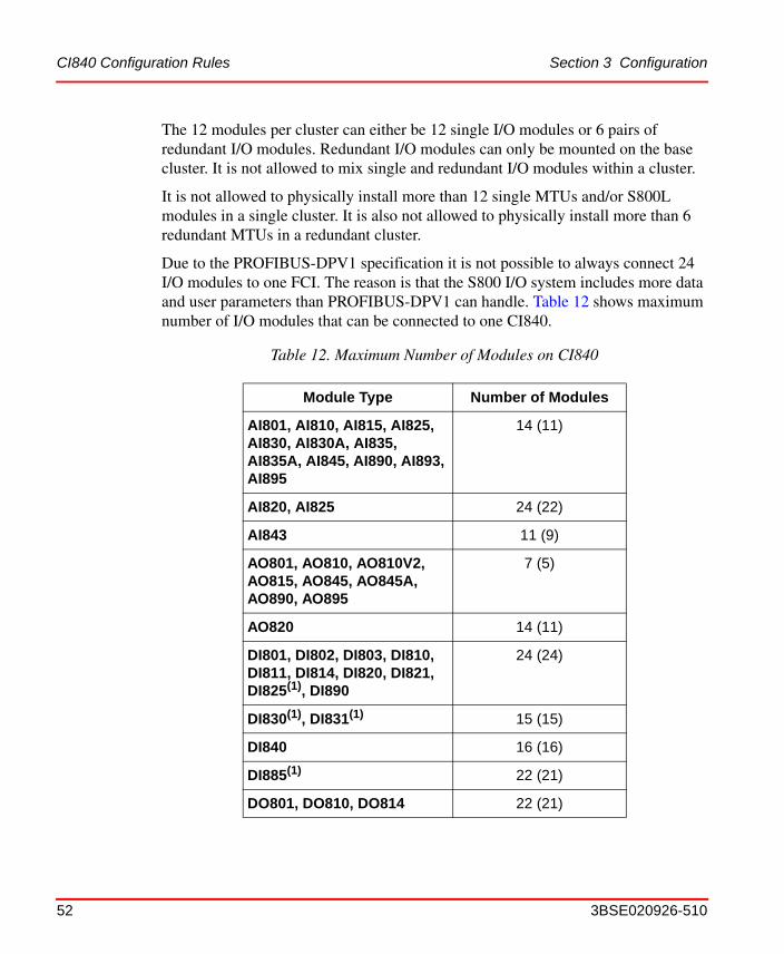
The 12 modules per cluster can either be 12 single I/O modules or 6 pairs of redundant I/O modules. Redundant I/O modules can only be mounted on the base cluster. It is not allowed to mix single and redundant I/O modules within a cluster.
It is not allowed to physically install more than 12 single MTUs and/or S800L modules in a single cluster. It is also not allowed to physically install more than 6 redundant MTUs in a redundant cluster.
Due to the PROFIBUS-DPV1 specification it is not possible to always connect 24 I/O modules to one FCI. The reason is that the S800 I/O system includes more data and user parameters than PROFIBUS-DPV1 can handle. Table 12 shows maximum number of I/O modules that can be connected to one CI840.
Table 12. Maximum Number of Modules on CI840
Module Type Number of Modules
AI801, AI810, AI815, AI825, AI830, AI830A, AI835, AI835A, AI845, AI890, AI893, AI895
14 (11)
AI820, AI825 24 (22)
AI843 11 (9)
AO801, AO810, AO810V2, AO815, AO845, AO845A, AO890, AO895
7 (5)
AO820 14 (11)
DI801, DI802, DI803, DI810, DI811, DI814, DI820, DI821, DI825(1), DI890
24 (24)
DI830(1), DI831(1) 15 (15)
DI840 16 (16)
DI885(1) 22 (21)
DO801, DO810, DO814 22 (21)

Section 3 Configuration CI840 Configuration Rules
3BSE020926-510 53
The values in brackets are in Extended HART mode and HCIR.
In order to find out if a given configuration of analog and digital modules can be used the following method should be used:
• Fill in number of modules in Table 13.
• Calculate the sum in the three columns:
– Sum User Parameters.
– Sum Input Bytes.
– Sum Output Bytes.
• Calculate the three total sums for:
– ParamSize.
– InSize.
– OutSize.
• Check that:
– ParamSize is less than or equal to 221 (220 if HCIR is used) in normal mode, 218 (217 if HCIR is used) in Extended HART mode.
– InSize is less than or equal to 239 in normal mode, 199 in Extended HART mode.
– OutSize is less than or equal to 112 in normal mode, 90 in Extended HART mode.
DO840 20 (19)
All other DO8XX 24 (24)
DP820 8 (6)
DP840 7 (5)
(1) Not supported by AC 800M
Table 12. Maximum Number of Modules on CI840 (Continued)
Module Type Number of Modules

CI840 Configuration Rules Section 3 Configuration
54 3BSE020926-510
If any of these three values is too high then the configuration can not be used.
Table 13. Calculation of Number of Modules on CI840
Module Type
User Parameters
Input Bytes
Output Bytes
Number of
Modules
Sum User Para-
meters
Sum Input Bytes
Sum Output Bytes
AI801 13 17 0
AI810 13 17 0
AI815 13 17 0
AI820 9 9 0
AI825 9 9 0
AI830/AI830A
12 17 0
AI835 15 17 0
AI835A 16 17 2
AI843 16 20 2
AI845 13 17 0
AI890 13 17 0
AI893 15 17 0
AI895 13 17 0
AO801 17 1 16
AO810/AO810V2
17 1 16
AO815 18 1 16
AO820 11 1 8
AO845/AO845A
18 1 16
AO890 17 1 16

Section 3 Configuration CI840 Configuration Rules
3BSE020926-510 55
AO895 17 1 16
DI801 7 4 0
DI802 6 2 0
DI803 6 2 0
DI810 7 4 0
DI811 7 4 0
DI814 7 4 0
DI820 6 2 0
DI821 6 2 0
DI825(1) 9 2 0
DI830(1) 14 4 0
DI831(1) 14 4 0
DI840 13 4 0
DI885(1) 10 2 0
DI890 7 2 0
DO801 10 2 2
DO802 7 1 1
DO810 10 2 2
DO814 10 2 2
DO815 8 1 1
DO820/821
7 1 1
Table 13. Calculation of Number of Modules on CI840 (Continued)
Module Type
User Parameters
Input Bytes
Output Bytes
Number of
Modules
Sum User Para-
meters
Sum Input Bytes
Sum Output Bytes

Supported I/O Modules and Drives via PROFIBUS and CI801 Section 3 Configuration
56 3BSE020926-510
Supported I/O Modules and Drives via PROFIBUS and CI801
The following I/O modules are supported by the PROFIBUS Field Communication Interface module CI801:
• AI801, AI810, AI815, AI820, AI825, AI830, AI830A, AI835, AI835A, AI843, AI845, AI890, AI893, AI895.
• AO801, AO810, AO810V2, AO815, AO820, AO845, AO845A, AO890, AO895.
• DI801, DI802, DI803, DI810, DI811, DI814, DI820, DI821, DI840 (SOE handling not supported), DI890.
• DO801, DO802, DO810, DO814, DO815, DO820, DO821, DO840, DO890.
• DP820, DP840.
• ABB Standard Drives. Have to be connected via TB820.
– ACS400 with standard drive
– ACS600 with standard application
– ACS800 with standard application
– ACS600 with crane application
DO840 11 2 2
DO890 6 1 1
DP820 12 18 13
DP840 10 34 0
Total sum - - - ParamSize InSize OutSize
(1) Not supported by AC 800M
Table 13. Calculation of Number of Modules on CI840 (Continued)
Module Type
User Parameters
Input Bytes
Output Bytes
Number of
Modules
Sum User Para-
meters
Sum Input Bytes
Sum Output Bytes
Section 3 Configuration Supported I/O Modules and Drives via PROFIBUS and CI830
3BSE020926-510 57
– ACS800 with crane application
– ACS600 with pump and fan application (PFC)
– ACS800 with pump and fan application (PFC)
– DCS400 with standard drive
– DCS500 with standard drive
– DCS600 with crane application
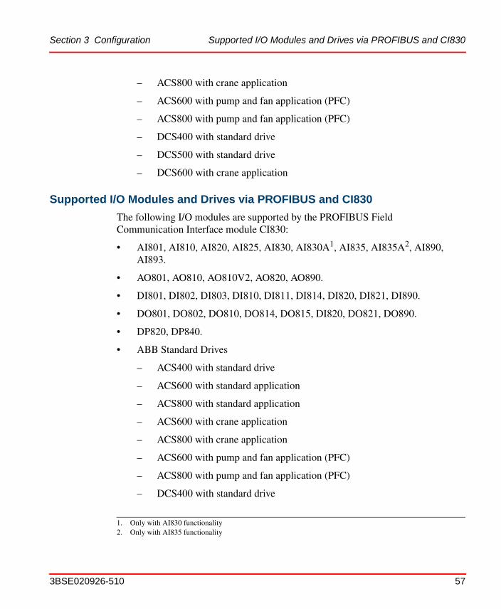
Supported I/O Modules and Drives via PROFIBUS and CI830
The following I/O modules are supported by the PROFIBUS Field Communication Interface module CI830:
• AI801, AI810, AI820, AI825, AI830, AI830A1, AI835, AI835A2, AI890, AI893.
• AO801, AO810, AO810V2, AO820, AO890.
• DI801, DI802, DI803, DI810, DI811, DI814, DI820, DI821, DI890.
• DO801, DO802, DO810, DO814, DO815, DI820, DO821, DO890.
• DP820, DP840.
• ABB Standard Drives
– ACS400 with standard drive
– ACS600 with standard application
– ACS800 with standard application
– ACS600 with crane application
– ACS800 with crane application
– ACS600 with pump and fan application (PFC)
– ACS800 with pump and fan application (PFC)
– DCS400 with standard drive
1. Only with AI830 functionality2. Only with AI835 functionality

Supported I/O Modules via PROFIBUS and CI840 Section 3 Configuration
58 3BSE020926-510
– DCS500 with standard drive
– DCS600 with crane application
Supported I/O Modules via PROFIBUS and CI840
The following I/O modules are supported by the PROFIBUS Field Communication Interface module CI840:
• AI801, AI810, AI815, AI820, AI825, AI830, AI830A, AI835, AI835A, AI843, AI845, AI890, AI893, AI895.
• AO801, AO810, AO810V2, AO815, AO820, AO845, AO845A, AO890, AO895.
• DI801, DI802, DI803, DI810, DI811, DI814, DI820, DI821, DI8251, DI8301,
• DI8311, DI840 (SOE handling not supported), DI8851, DI890.
• DO801, DO802, DO810, DO814, DO815, DO820, DO821, DO840, DO8902.
• DP820, DP840.
Data Scanning
ModuleBus data is scanned (read or written) cyclically, depending on the I/O module configuration. To calculate the I/O scan cycle time in the FCI do as follows:
Totalize (number of module type x) * (used execution time for type x)(see Table 14) if the value is a multiple of 2 add 2 to the value. Otherwise increase
1. Not supported by AC 800M

Section 3 Configuration Data Scanning
3BSE020926-510 59
the total value to the nearest higher multiple of two (2) to get the I/O scan cycle time.
Table 14. I/O Scan Cycle Time in the FCI
Module Type
Execution Time Used in ms
CI801 CI830
CI840
Single I/ORedundant I/O pair
AI801, AI810, AI890, AI895 3.00 3.00 3.00 -
AI820, AI825 1.50 1.50 1.50 -
AI830, AI830A, AI835, AI835A, AI893
0.40 0.40 0.40 -
AI843 0.40 - 0.40 0.80
AI815, AI845 3.00 - 3.00 6.00
AO801, AO810, AO810V2, AO815, AO890, AO895
1.20 1.20 1.20 -
AO820 0.60 0.60 0.60 -
AO845, AO845A 1.20 - 1.20 2.40
DI801, DI802, DI803, DI810, DI811, DI814, DI820, DI821
0.43 0.43 0.50 -
DI840 0.43 - 0.50 1.00
DI890 0.43 0.43 0.50 -
DO801, DO802, DO810, DO814, DO815, DO820, DO821
0.43 0.43 0.50 -
DO840 0.43 - 0.50 1.00
DO890 0.43 0.43 0.50 -
DP820 1.72 1.72 2.09 -
Data Scanning Section 3 Configuration
60 3BSE020926-510
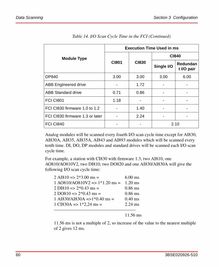
Analog modules will be scanned every fourth I/O scan cycle time except for AI830, AI830A, AI835, AI835A, AI843 and AI893 modules which will be scanned every tenth time. DI, DO, DP modules and standard drives will be scanned each I/O scan cycle time.
For example, a station with CI830 with firmware 1.3, two AI810, one AO810/AO810V2, two DI810, two DO820 and one AI830/AI830A will give the following I/O scan cycle time:
2 AI810 => 2*3.00 ms = 6.00 ms1 AO810/AO810V2 => 1*1.20 ms = 1.20 ms2 DI810 => 2*0.43 ms = 0.86 ms2 DO810 => 2*0.43 ms = 0.86 ms1 AI830/AI830A =>1*0.40 ms = 0.40 ms1 CI830A => 1*2,24 ms = 2.24 ms------------------------------------------------------
11.56 ms
11.56 ms is not a multiple of 2, so increase of the value to the nearest multiple of 2 gives 12 ms.
DP840 3.00 3.00 3.00 6.00
ABB Engineered drive - 1.72 - -
ABB Standard drive 0.71 0.86 - -
FCI CI801 1.18 - - -
FCI CI830 firmware 1.0 to 1.2 - 1.40 - -
FCI CI830 firmware 1.3 or later - 2.24 - -
FCI CI840 - - 2.10
Table 14. I/O Scan Cycle Time in the FCI (Continued)
Module Type
Execution Time Used in ms
CI801 CI830
CI840
Single I/ORedundant I/O pair

Section 3 Configuration Data Scanning
3BSE020926-510 61
That will give an I/O scan cycle time of 12 ms between the FCI and its I/O modules. This means that the DIs and DOs will be scanned every 12 ms, the AI810s and the AO810/AO810V2 every (4*12 ms) 48ms and the AI830/AI830A every (10*12 ms) 120 ms.
For example, a station with CI801, two AI810, one AO810/AO810V2, two DI810, two DO820 and one AI830/AI830A will give the following I/O scan cycle time:
2 AI810 => 2*3.00 ms = 6.00 ms1 AO810/AO810V2 => 1*1.20 ms = 1.20 ms2 DI810 => 2*0.43 ms = 0.86 ms2 DO810 => 2*0.43 ms = 0.86 ms1 AI830/AI830A =>1*0.40 ms = 0.40 ms1 CI801 => 1*1.18ms = 1.18 ms------------------------------------------------------
10.50 ms
10.50 ms is not a multiple of 2, so increase of the value to the nearest multiple of 2 gives 12 ms.
That will give an I/O scan cycle time of 12 ms between the FCI and its I/O modules. This means that the DIs and DOs will be scanned every 12 ms, the AI810s and the AO810/AO810V2 every (4*12 ms) 48 ms and the AI830/AI830A every (10*12 ms) 120 ms.
For example, a station with CI840, single or redundant, two AI810, one AO810/AO810V2, two DI810, two redundant pairs of DO840 and one redundant pair of AI845 will give the following I/O scan cycle time:
2 AI810 => 2*3.00 ms = 6.00 ms1 AO810/AO810V2 => 1*1.20 ms = 1.20 ms2 DI810 => 2*0.50 ms = 1.00 ms2 DO840 => 2*1.00 ms = 2.00 ms1 AI845 =>1*6.00 ms = 6.00 ms1 CI840 => 1*2.10 ms = 2.10 ms
Minimum I/O scan cycle time = 4 ms with firmware 1.0 to 1.2.Minimum I/O scan cycle time = 6 ms with firmware 1.3 or later.
Minimum I/O scan cycle time = 4 ms

Data Scanning Section 3 Configuration
62 3BSE020926-510
------------------------------------------------------18.30 ms
18.30 ms is not a multiple of 2, so increase of the value to the nearest multiple of 2 gives 20 ms.
That will give an I/O scan cycle time of 20 ms between the FCI and its I/O modules. This means that the DIs and DOs will be scanned every 20 ms, the AI810s and the AO810/AO810V2 every (4*20 ms) 80 ms and the AI830/AI830A every (10*20 ms) 200 ms.
Minimum I/O scan cycle time = 4 ms

3BSE020926-510 63
Section 4 Operation
Operating OverviewAn I/O station is an autonomous station which normally is not handled by an operator. Of course, it is started and sometimes stopped manually. This is done, however, in specific situations such as the time of installation work and maintenance.
Accordingly, operating instructions are spread out in this manual. See where the specific activity is treated.
For general descriptions, see the beginning of this section. For concrete instructions, see Section 2, Installation and Section 5, Maintenance.
Getting Started
Functional Description
This section describes the functionality and services that the FCI (Fieldbus Communication Interface) offers for a PROFIBUS Master via PROFIBUS-DP/DPV1. This includes a general description of the data flow on PROFIBUS-DP/DPV1, and how the S800 I/O modules are operated and treated.
The FCI acts as a pure slave station on PROFIBUS-DP/DPV1. The FCI controls all operations of an S800 I/O station. It is the bus-master on the S800 I/O ModuleBus. It does this by handling all communications between the PROFIBUS Master and the S800 I/O modules.
The FCI scans all dynamic input data from the input modules and sends it on PROFIBUS-DP/DPV1, and writes all dynamic output data received from PROFIBUS-DP/DPV1 to the output modules.

Functional Description Section 4 Operation
64 3BSE020926-510
The FCI is responsible for:
• Module configuration and supervision.
• Performing signal conditioning on input and output values.
• Dynamic data transfer.
Module Configuration and Supervision
The FCI stores the configuration for all configured I/O Modules in the station.
The FCI will continuously supervise all I/O modules being configured by the PROFIBUS Master. It sends the status of all modules to the PROFIBUS Master via PROFIBUS-DP/DPV1.
When the FCI detects an I/O module without configuration, which it has configuration data for, it will automatically load the parameters to the module. The module is then automatically set into operation by the FCI.
Signal Conditioning
The FCI performs the signal conditioning (for example, linearization and filtering) for the more basic I/O modules. This means that the FCI has to make some computation before moving the value to the module or after reading the value from the module. The type of signal conditioning to perform depends on the module type and its configuration (parameter settings).
Intelligent I/O modules do signal conditioning themselves. In this case the FCI only has to move the value to or from the module. This means less load on the FCI which can be used on other modules or services.
Dynamic Data Transfer
Figure 18 gives an overview of how the exchange of dynamic process data is transferred back and forth between the user application and the actual process.

Section 4 Operation Functional Description
3BSE020926-510 65
The transportation of dynamic data between PROFIBUS-DP/DPV1 and the ModuleBus is the main task for the FCI. The FCI has a dedicated memory area where it sends the output values and reads the input values. The CPU in the FCI performs the rest of the data transportation. It reads output values from the memory and writes to the I/O Modules via the ModuleBus and vice versa.
Figure 18. Dynamic Data Exchange for PROFIBUS-DP/DPV1 in Runtime
Process
PROFIBUS Master (Class 1)
Fieldbus Communication
Input Module
PROFIBUS
Output Module
ValuesChan x
ValuesChan x
4.
1.
5.
2.
3.
6.
Dynamic Data Exchange
Interface (FCI)Communication Memory
Data exchange with PROFIBUS-D3 and 4
Input and output values are updated as fast as possible (depends on the
2 and 5
configuration). Signal conditioning is
Input and output values are updated “as fast as possible” (depends on the
1 and 6
S800 I/O module configuration).
also performed in this loop.
data from Master to FCI as well ascyclic and consists of both writing
The PROFIBUS Master uses Data Exchangerequest towards the FCI according to it’sscheduling scheme.
read from FCI to Master.

Functional Description Section 4 Operation
66 3BSE020926-510
Data Scanning Principles
The data transfer between PROFIBUS-DP/DPV1 and the ModuleBus is not synchronized. Read and write operations are performed from and to a dual port memory in the FCI.
The ModuleBus data is scanned (read or written) cyclically, depending on the I/O module configuration. On one scan all digital modules, 1/4 of the analog modules and 1/10 of the slow analog modules are scanned. It takes 4 scans to read all analog modules and 10 scans to read all slow analog modules.
Redundant FCI
CI840 can work as a redundant pair where one FCI is primary and one is backup. As long as the primary works correct it will handle both the PROFIBUS and the ModuleBus. Both FCIs supervise each other. If a fault occurs in the primary the backup will automatically take over.
Hot Configuration In Run
CI801 and CI840 supports the function Hot Configuration In Run (HCIR).
HCIR is a function for modifying field device configuration without disturbing the running system. The following actions can be done:
• Delete modules
• Insert modules
• Parameter changes
During the configuration the values are frozen for a short moment. The time is dependent of the PROFIBUS master, communication speed, CI801, CI840, type of configuration and type of changes. Typical 300 ms at a communication speed of 1.5 MHz.
The configuration time is supervised by a watchdog. If the watchdog time elapse, the outputs will go to OSP (Output Set as Predefined). The watchdog time consists of two parts, one part calculated by the PROFIBUS master and one fix part for the slave (CI801 and CI840 1200 ms).

Section 4 Operation I/O Module Functionality
3BSE020926-510 67
HART
The HART communication in CI801 and CI840 is based on Profibus-DPV1 services. The maximum size of the HART frame structure is 64 byte in normal mode and 227 byte in Extended HART mode. For more information see Memory Maps for CI801 (3BSE036959*) or Memory Maps for CI840 (3BSE025251*).
DPV1 Services
For information about Profibus DPV1 services see Memory Maps for CI801 (3BSE036959*) or Memory Maps for CI840 (3BSE025251*).
I/O Module Functionality
All S800 I/O modules have some common functionality. This section describes these common functions of the I/O modules.
An S800 I/O module complies with the following framework:
• General
– It has a Module Identity (see Module Identity on page 68).
– It has a state that can be controlled (see Module States on page 68).
– It reports status for modules and channels.
• Parameters
– It may have configuration parameters for the module and the channels.
– It may have non-volatile parameters for each channel (factory settings).
• Dynamic values
– All channels have dynamic values including quality indications.
– All output channels can be read for verification of the performance and health.

I/O Module Functionality Section 4 Operation
68 3BSE020926-510
Module Identity
All S800 I/O modules contains a module identity. The module identity is used to verify that an I/O module of the expected (user configured) type is mounted before taking it operational. It protects the system from performing unexpectedly.
Module States
The figure below shows the states of the I/O modules.
Figure 19. I/O Module States
Init
Not
Ready
Ope-
OSP
NOT Reset AND 5 V OK
Commanded to Operational state
Commanded toNot Configured
Communication time-out
Output modules only
Error
From all other states:Fatal error detected by module
rational
Restart-Command
Commanded to
From ALL states:
Configured
Operational state
Parameter loaded
state

Section 4 Operation I/O Module Functionality
3BSE020926-510 69
The states are described in more detail below:
Init State
In the Init state the actual initialization of the module is performed, including a self-test.
Inputs Not scannedOutputs Inactive: 0 VLEDs Fault
Not Configured State
In the Not Configured state the module waits to be configured. The FCI performs the parameter download to the module.
Inputs Not scannedOutputs Inactive:0 VLEDs Fault until first ModuleBus dialog, then None
(and/or Warning if diagnostic warning)
Ready State
Entering the Ready state starts input channel scanning. All active channels are scanned before the state is completely entered. In this state the module just waits to be commanded to the Operational state.
Inputs ScannedOutputs Inactive: 0 VLEDs None (or Warning if diagnostic warning)
Operational State
This is the state for normal operation. After entering the Operational state (from Ready or OSP), output channels are still unchanged until a valid output value is written.
Inputs ScannedOutputs ActiveLEDs Run (and Warning if diagnostic warning)

I/O Module Functionality Section 4 Operation
70 3BSE020926-510
OSP (Outputs Set as Predefined) State
The OSP state is only used by modules with output channels. If OSP is activated it is entered from the Operational state in two cases:
• The supervision time-out on PROFIBUS-DP/DPV1 has elapsed.
• The OSP-watchdog expires, no access has been done to the module within 1024 ms (analog) 256 ms (digital).
See OSP-Watchdog on page 71.
Entering the OSP state the module sets its outputs to the predetermined values. This means “Keep value” or output the configured OSP value. The outputs are kept unchanged as long as the module stays in the OSP state.
When the PROFIBUS-DP/DPV1 network is operating again the FCI orders the module out of the OSP state.
After re-entering the Operational state, the outputs are still unchanged until valid values are written.
Inputs Not applicableOutputs According to configuration (keep value or OSP value)LEDs Run, OSP (and Warning if diagnostic warning)
Error State
This the state that will be entered if a fault is detected.
Inputs Not scannedOutputs Inactive (0 V)LEDs Fault
Configuration, Parameters
Configuring an I/O module is equal to writing the parameters to it.
The parameters for a module can mainly be divided into configuration parameters and non-volatile parameters.

Section 4 Operation I/O Module Functionality
3BSE020926-510 71
Loading Parameters
At start-up, the configuration parameters are loaded by the FCI in the NotConfigured state. When valid configuration parameters are written to the module, it will change from the Not Configured state to the Ready state. After entering the Ready state the module may be set to Operational.
The parameters do not need to be remembered on the modules after a reset of the module since they are saved in the FCI.
Loading Invalid Parameters
If parameters that are in some way invalid are sent to a module, this is indicated with a warning in the module status and by a diagnostic message. If channel parameters are invalid an error on the channel is indicated.
Non-volatile Parameters
Each channel may, apart from the configuration parameters, also have non-volatile parameters that are stored on the module and written during production and are not changed by a running system.
OSP-Watchdog
The OSP-watchdog is a watchdog timer that all I/O modules with output channels have. It supervises the communication to discover if the traffic on the ModuleBus is interrupted. The OSP-watchdog is refreshed when the module is accessed. If this is not done within the time limit the watchdog will force the module to the OSP state (see Module States on page 68).
The OSP-watchdog is also activated when the PROFIBUS-DP/DPV1 watchdog has elapsed. The supervision time for PROFIBUS-DP/DPV1 is defined in the PROFIBUS configuration tool.
The watchdog on PROFIBUS must be enable to get the OSP function to work on AO and DO modules at communication error on PROFIBUS.
The watchdog time-out should be set to at least four times the PROFIBUS’s cycle time.

I/O Module Functionality Section 4 Operation
72 3BSE020926-510

3BSE020926-510 73
Section 5 Maintenance
Preventive MaintenanceRefer S800 I/O Getting Started (3BSE020923*).
Hardware Indicators
CI801 FCI Module LEDs
The CI801 FCI has indicators for fault, operational state, power condition, and PROFIBUS communication traffic. Table 15 describes the LEDs, and Figure 20 shows the location of the LEDs on the module.
Table 15. Standard LEDs on CI801 FCI Module
LED Color Description
F (Fault) Red Fault in the module (1)
(1) The F-LED lights up at power up, restart of the module, or when the module goes to Error state. At the start up, the module does a self test; if the self test is OK, the module turns off the F-LED.
R (Run) Green Operational state
P (Power ok) Green Internal power OK
T (Traffic) Yellow Receive transmit data on PROFIBUS

CI801 FCI Module LEDs Section 5 Maintenance
74 3BSE020926-510
Figure 20. CI801 FCI with Status LEDs Location
LED StatusIndicators

Section 5 Maintenance CI830 FCI Module LEDs
3BSE020926-510 75
CI830 FCI Module LEDs
The CI830 FCI has indicators for fault, operational state, power status, PROFIBUS communication status, and optical ModuleBus communication status. Table 16 describes the LEDs, and Figure 21 shows the location of LEDs on the module.
Table 16. Standard LEDs on CI830 FCI Module with TB810/TB811
LED Color Description
F (Fault) Red Fault in the module (1)
(1) The F-LED lights up at power up, restart of the module, or when the module goes to Error state. At the start up, the module does a self test; if the self test is OK, the module turns off the F-LED.
R (Run) Green Operational state
P (Power ok) Green Internal power OK
RX (Receive) Yellow Receive data on PROFIBUS
TX (Transmit) Yellow Transmit data on PROFIBUS
Tx (TB810/TB811) Yellow Transmit data on the optical ModuleBus
Rx (TB810/TB811) Yellow Receive data on the optical ModuleBus

CI830 FCI Module LEDs Section 5 Maintenance
76 3BSE020926-510
Figure 21. CI830 FCI with TB810/TB811 Status LEDs Location
STN. ADDR.
F R
TXRX
P
SERVICE
CI830
012
9
75
38
4 6
012
9
75
38
4 6
x 10
x 1
PROFIBUS
IndicatorsLED Status
Tx
Rx
Tx RxSWX.X/Y
PROFIBUS
L+
L-
SASB
TB810/TB811

Section 5 Maintenance CI840 FCI Module LEDs
3BSE020926-510 77
CI840 FCI Module LEDs
The CI840 FCI has indicators for fault, operational state, power status, PROFIBUS communication state, and for the state in a redundant configuration. Table 17 describes the LEDs, and Figure 22 shows the location of the LEDs on the module.
Table 17. Standard LEDs on CI840 FCI Module
LED Color Description
F (Fault) Red Fault in the module (1)
(1) The F-LED lights up at power up, restart of the module, or when the module goes to Error state. At the start up, the module does a self test; if the self test is OK, the module turns off the F-LED.
R (Run) Green Operational state
P (Power ok) Green Internal power OK
Rx/Tx (Traffic) Yellow Receive transmit data on PROFIBUS
PRIM (Primary) Yellow Working as Primary
DUAL Yellow Working with a partner

Error Messages Section 5 Maintenance
78 3BSE020926-510
Error MessagesPlease see the relevant PROFIBUS Master documentation.
Figure 22. CI840 FCI with Status LEDs Location
CI840 CI840
IndicatorsLED Status
FR
PRIM
PRx/Tx
DUAL
FR
PRIM
PRx/Tx
DUAL

Section 5 Maintenance Fault Finding and Repair
3BSE020926-510 79
Fault Finding and Repair
Communication Module Replacement
General
Communication modules CI801, CI830, and TB820 cannot be replaced online.
Communication modules CI840 and TB840 can be replaced online.
The following notes are applicable to replacement of modules, and its effect on the process:
• Replacement of a communication module type CI801 and CI830 affects all channels on all the modules in an I/O station. The station will loose power.
• Replacement of a communication module type CI840 in a redundant configuration does not affect any channel in an I/O station.
• Replacement of an optical port type TB810/TB811/TB842 affects all channels on all the modules in all clusters, except cluster 0. The communication to all clusters is broken, except for cluster 0.
• Replacement of an optical modem type TB820, or TB840 in a single configuration, connected through a simplex optical cable, affects all channels on all the modules in all clusters except cluster 0. The communication to all clusters is broken, except for cluster 0. The cluster where the TB820 should be replaced will be powerless.
• Replacement of an optical modem type TB820 or TB840, in a single configuration, connected through a duplex optical cable, affects all channels on all the modules in the cluster and also in all clusters that are located after the cluster where the replaced TB820 or TB840 is located. The communication to all clusters located after the cluster where the replaced TB820 or TB840 is located, will be broken. The cluster where TB820 or TB840 should be replaced will be powerless.
• Replacement of a communication module type TB840 in a redundant configuration does not affect the channels in an I/O station.

Communication Module Replacement Section 5 Maintenance
80 3BSE020926-510
The following topics contain general instructions for replacement of modules, and Table 18 provides additional information on the handling of individual modules.
Practical Execution
Before replacing the modules:
1. Read the S800 I/O Getting Started (3BSE020923*) manual.
2. As special restrictions apply to each module type, see the descriptions in Table 18 for useful information on individual module types.
3. Check whether the new module, CI801/CI830/CI840, can be a suitable replacement, and check the software version. If the wrong software version is found, load the new software (see Backup/Restore Procedures on page 84).
To replace faulty communication modules:
1. Disconnect the power supply/supplies from the module.
2. Disconnect the PROFIBUS and ModuleBus from the module.
3. Extract the module.
4. Set the current Station address or Cluster address on the new module.
5. Insert the new module carefully.
6. Connect the PROFIBUS and ModuleBus to the module.
7. Connect the power supply/supplies to the module.
8. Store extracted modules in protective envelopes.
The modules are initialized automatically by the system, and it takes approximately 60 seconds for a CI801/CI830/CI840 to start up.
Additional Information on Individual S800 Communications Modules
Table 18 provides additional information for replacement of S800 I/O modules.
For replacing CI840, perform only the steps 3, 5 and 8, in the procedure described below.

Section 5 Maintenance Communication Module Replacement
3BSE020926-510 81
Table 18. Replacement of S800 I/O Modules
Module Type - Settings Comments
CI801FCI
Switch setting for PROFIBUS address
Cannot be replaced with power applied.
Needs space to the left in order to be removed.
In normal operation mode, before a CI801 is replaced, the supply to the S800 I/O is to be switched off. Power connections can be removed by pulling the header terminals out of the unit.
Optical ModuleBus Port TB842 can not be removed with power applied.
If a TB842 connected to a CI801 shall be changed in a running system, TB806 has to be disconnected from the FCI first.
The fuse for ModuleBus 24 V can be changed if the top cover of the module is removed. For fuse type, see CI801 Technical Data.
Fieldbus connections can be removed by pulling the D-way connector out of the unit.
If the last CI801 on a PROFIBUS segment supplies an active termination in the cable connector, disconnection of the power supply or the PROFIBUS cable to CI801 cannot be done without disrupting the bus.
Station AddreSwitches

Communication Module Replacement Section 5 Maintenance
82 3BSE020926-510
CI830FCI
Switch setting for PROFIBUS address
Cannot be replaced with power applied.
Needs space to the left in order to be removed.
In normal operation mode, before a CI830 is replaced, the supply to the S800 I/O is to be switched off. Power connections can be removed by pulling the header terminals out of the unit.
Optical ModuleBus Port TB810/TB811 cannot be removed with power applied.
Fieldbus connections can be removed by pulling the D-way connector out of the unit.
If the last CI830 on a PROFIBUS segment supplies an active termination in the cable connector, disconnection of the power supply or the PROFIBUS cable to CI830 can not be done without disrupting the bus.
CI840/TB840
Can be replaced with power applied.
In redundant configuration, one CI840/TB840 can be replaced without any affects on channel in an I/O station.
If a TB842 connected to a TU846/TU847 shall be changed in a running system, TB806/TB846 has to be disconnected from TU846/TU847 first.
If the last CI840 on a PROFIBUS segment supplies an active termination in the cable connector, disconnection of the power supply or the PROFIBUS cable to CI840 cannot be done without disrupting the bus. Also, CI840 cannot be removed.
TU846/TU847
Needs space to the left in order to be removed. Cannot be replaced with power applied.
Table 18. Replacement of S800 I/O Modules
Module Type - Settings Comments
Station AddreSwitches
STN. ADDR.
F R
TXRX
P
SERVICE
CI830
012
9
75
38
4 6
012
9
75
38
4 6
x 10
x 1
PROFIBUS
Tx
Rx
Tx Rx
PROFIBUS
L+
L-
SASB
Cluster AddresSwitches

Section 5 Maintenance Application Memory Reset
3BSE020926-510 83
Application Memory Reset
A CI830 can keep an application in memory for a long time, even with the power supply disconnected. To avoid a problem with an FCI that may have an old application, the application memory should be cleared.
To clear the application memory in CI830:
1. Set the address switches to 99.
2. Remove the power supply for a short moment.
3. Apply power and allow the FCI to restart. Wait for 45 seconds.This clears the application memory.
4. Set the address switches to the desired station address.
5. Remove the power supply for a short moment.
6. Apply power and allow the FCI to restart. Wait for 45 seconds.
This makes the module ready for the new application.
CI801 Firmware version
It is possible to read the firmware version from the service port (PROFIBUS connection), at startup.
To read the firmware version:
1. Connect a PC to the service port of the CI801 via the service adapter (FS801 and TK802) and cable TK212/TK212A, see Figure 23.
2. Start a terminal program in the PC (for example, Hyperterminal).
3. Set the communication parameters to 9600 bps, 8 bits word length, no parity, 1 bit stop.
4. Set the station address to 0.
5. Disconnect power to the CI801, and connect the power again.The LEDs, F and P, light up.
6. When the CI801 has started up (F LED is off after about 30 seconds), it writes a text string on the terminal program, containing the version number (for example, CI801 SW 1.0/0).

CI840 Firmware version Section 5 Maintenance
84 3BSE020926-510
CI840 Firmware version
From CI840 firmware version 3.0/0 and later, it is possible to read its firmware version from the service port, at startup.
In a redundant pair, the firmware version can be read from the backup module. A change over from primary state to backup state can be done by the DTM or by disconnecting the PROFIBUS cable on the primary.
To read the firmware version:
1. Connect the PC to the CI840 (TU846/TU847), using a TK212/TK212A cable between the RS232 service port A or B on the TU846/TU847 (CI840) and the COM1 or COM2 on the PC.
2. Start a terminal program in the PC (for example, Hyperterminal).
3. Set the communication parameters to 9600 bps, 8 bits word length, no parity, 1 bit stop.
4. Disconnect the power to the CI840, and connect the power again by unlocking the screw and locking it again.
5. When the CI840 has started up (after about 30 seconds), it writes a text string on the terminal program, containing the version number (for example, CI840 SW 3.0/0).
Backup/Restore Procedures
Load the CI801 Software Upgrade
Hardware Requirements
• PC with WINDOWS NT 4 or later.
• Service adapter (FS801 + cable TK802) 3BSE038407R1
• Connection cable TK212 3BSC630167R2 or TK212A 3BSC630197R1
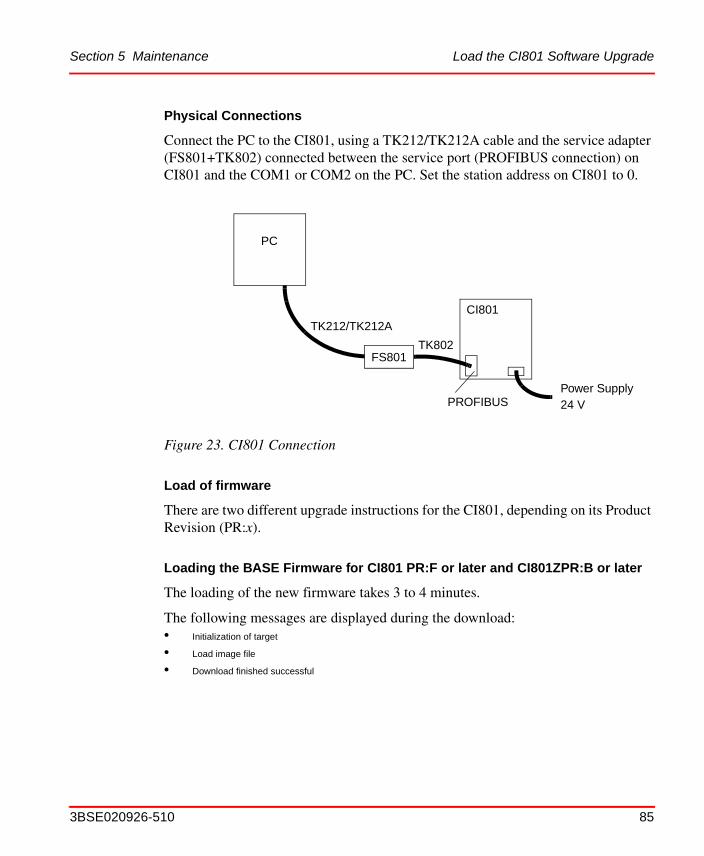
Section 5 Maintenance Load the CI801 Software Upgrade
3BSE020926-510 85
Physical Connections
Connect the PC to the CI801, using a TK212/TK212A cable and the service adapter (FS801+TK802) connected between the service port (PROFIBUS connection) on CI801 and the COM1 or COM2 on the PC. Set the station address on CI801 to 0.
Load of firmware
There are two different upgrade instructions for the CI801, depending on its Product Revision (PR:x).
Loading the BASE Firmware for CI801 PR:F or later and CI801ZPR:B or later
The loading of the new firmware takes 3 to 4 minutes.
The following messages are displayed during the download:• Initialization of target
• Load image file
• Download finished successful
Figure 23. CI801 Connection
PC
TK212/TK212A
TK802
CI801
Power Supply24 VPROFIBUS
FS801

Load the CI801 Software Upgrade Section 5 Maintenance
86 3BSE020926-510
To load the firmware:
1. Run the program, loader32_42-1.exe.
2. Click Next.
3. Select the COM-Port to use, and enter the path to the image file.
4. Click Download.
5. When the download is finished, set the station address back to the used address.
6. Switch off the power supply and then switch on the power supply, to restart CI801.
Loading the BASE Firmware for CI801 PR: A to E and CI801Z PR: A
The loading of the new firmware takes about 15 minutes.
The following messages are displayed during the download:• Initialization of target
• Load image file
• Download finished successful
To load the firmware:
1. Run the program, loader32_42-1.exe.
2. Click Next.
3. Select the COM-Port to use, and enter the path to the image file.
4. Disconnect power to CI801 and connect the power again.
5. Wait for the FCI to start up, and then click Download.
6. When the download is finished, set the station address back to the used address.
7. Switch off the power supply and then switch on the power supply, to restart CI801.

Section 5 Maintenance Load the CI830 Software Upgrade
3BSE020926-510 87
Troubleshooting
Problem: The cable is disconnected during download, or the power went down.
Solution: Restart CI801 by switching the power OFF and then switching the power ON.
Labelling
Update the firmware version on the firmware label.
Connection cable
Load the CI830 Software Upgrade
Hardware Requirements
• PC with WINDOWS NT 4 or 2000.
• Connection cable TK527 (3BSC950004R1).
It is assumed that the PC communication port is COM1, and the diskette drive is A.
Reset the CI830 application memory. SeeApplication Memory Reset on page 83.
Figure 24. Cable TK212A 3BSC63197R1

Load the CI830 Software Upgrade Section 5 Maintenance
88 3BSE020926-510
Connection
Connect the PC and the CI830, using a TK527 (3BSC950004R1) cable between the RS232 service port on the CI830 and the COM1 or COM2 on the PC.
Loading the BASE Software
1. Run the program, loader32.exe.
2. Click Next.
3. Choose the setting User defined: Select COM-Port and speed manually.
4. Click Next.
5. Select the COM-Port to use, and enter the path to the image file.
6. Check the Disable optimization of speed (Fix to 9600 BD) checkbox, and uncheck the remaining check boxes.
7. Click Download.
The loading of the new firmware takes approximately 5 minutes.
Troubleshooting
Problem: The cable is disconnected during download, or the power supply goes off.
Solution: Restart the CI830 by switching power OFF and then switching the power ON.

Section 5 Maintenance Load the CI840 Software Upgrade
3BSE020926-510 89
Labelling
Put the largest label on the back of the CI830 and the smaller one on the front of CI830. See Figure 25.
Load the CI840 Software Upgrade
Hardware Requirements for CI840/CI840A rev. XX
• PC with Windows NT4 or later
• Connection cable TK212 3BSC630167R2 or TK212A 3BSC630197R1
Figure 25. CI830 Software Label Location
STN. ADDR.
F R
TxRXP
CI830
01297
53
84 6
01297
53
84 6
x 10
x 1
PROFIBUSSW*1.1/0Label
PROFIBUS
L+L-SASB

Load the CI840 Software Upgrade Section 5 Maintenance
90 3BSE020926-510
Connection
Connect the PC and the CI840 (TU846/TU847), using a TK212/TK212A cable between the RS232 service port A or B on the TU846/TU847 (CI840) and the COM1 or COM2 on the PC.
Loading the Firmware
There are two different upgrade instructions for the CI840A and CI840AZ, depending on its Product Revision (PR: x).
Loading the Firmware for CI840A PR: B or later and CI840AZ PR: B or later
The loading of firmware takes 3 to 4 minutes with loader32 4.2/1
The following messages are displayed during download:
• Initialization of target
• Load image file
• Download finished successful
Loading the Firmware on Single FCI
1. Run the program loader32_42-1.exe.
2. Click Next.
3. Select COM-Port to use, and enter the path to the image-file.
4. Click Download.
5. When the Initialization of target state is displayed, restart the CI840 by unlocking the screw and locking it again before the progress bar reaches 50%.
6. When the download is finished, the CI840 starts up automatically.
Loading the Firmware on Backup FCI when the Primary FCI is running
Follow the same instructions as for Single FCI.

Section 5 Maintenance Load the CI840 Software Upgrade
3BSE020926-510 91
Loading the Firmware in the Primary FCI when the Backup is Running
1. Perform a switch-over to put the Primary FCI in backup state. It can be done by using the DTM or disconnecting the PROFIBUS cable on the primary FCI.
2. Follow the same instructions as for Single FCI.
Loading the Firmware for CI840A PR: A, CI840AZ PR: A, and CI840
There is a small difference between upgrade of a CI840 with firmware 3.0/2 or earlier, and 3.1/0 or later.
The loading of firmware takes approximately 15 minutes.
The following messages are displayed during down load:• Initialization of target
• Load image file
• Down load finished successful
Loading the Firmware for Single FCI
1. Disconnect the PROFIBUS cable from the module that should be loaded.
2. Run the program loader32_42-1.exe.
3. Click Next.
4. Select COM-Port to use, and enter the path to the image-file.
5. Click Download, and continue with Step6 or Step9.
CI840 with firmware 3.0/2 or earlier
6. Interrupt the downloading by disconnecting the power to the CI840, wait for 20 seconds, and connect the power again.
7. Click Download.
8. When the download is finished, the CI840 starts up automatically.
CI840 with firmware 3.1/0 or later.
9. When the download is finished, the CI840 flashes all the LEDs for 1 second, and then turn on the red F(ault) LED.

Load the CI840 Software Upgrade Section 5 Maintenance
92 3BSE020926-510
10. Disconnect power to CI840 and connect the power again, for start up of CI840.
Loading the Firmware on Backup FCI when the Primary FCI is Running
CI840 with firmware 3.0/2 or earlier
11. Follow the instructions as for Single FCI, until Step 5.
The red F(ault) LED lights up.
12. Disconnect the power supply from the backup FCI by unlocking the screw, wait for 20 seconds, and lock it again.
13. Continue the procedure according to Single FCI from Step 7 without any waiting.
14. If the downloading does not start, repeat Step 12 and Step 13.
15. When the download is finished, the CI840 starts up automatically.
CI840 with firmware 3.1/0 or later.
16. Follow the instructions according to Single FCI until Step 5.
The red F(ault) LED lights up.
17. Disconnect the power supply from the backup FCI by unlocking the screw and locking it again.
18. Click Download.
19. If the downloading does not start, repeat Step 17 and Step 18.
20. When the download is finished, the CI840 starts up automatically.
Loading the firmware in the Primary FCI when the Backup is Running
21. Do a change over, so that the FCI that should be updated is in backup state. This can be done by the DTM or by disconnecting the PROFIBUS cable on the primary.
22. Load the firmware as in the topic Backup FCI when the Primary FCI is running.

Section 5 Maintenance Load the CI840 Software Upgrade
3BSE020926-510 93
Troubleshooting
Problem: Cable is disconnected during download or the power supply goes off.
Solution: Restart the CI840 by switching the power OFF and switching the power ON again.
Labelling
Update the firmware version on the firmware label.
Connection Cable
Figure 26. Cable TK212A 3BSC63197R1

Load the CI840 Software Upgrade Section 5 Maintenance
94 3BSE020926-510
.
Figure 27. CI840 and TU847
CI840 CI840
FR
PRIM
PRx/Tx
DUAL
FR
PRIM
PRx/Tx
DUAL
Service port
Position BPosition A

3BSE020926-510 95
Appendix A Specifications
CI801 Fieldbus Communications Interface (FCI)
Features
• PROFIBUS-DPV1 fieldbus interface.
• Supervisory functions of I/O ModuleBus.
• Isolated power supply to I/O modules.
• OSP handling and configuration.
• Input power fused.
• Hot Configuration In Run.
• HART pass-trough.
Description
The CI801 Fieldbus Communications Interface (FCI) is an intelligent communication interface between a Controller via the PROFIBUS-DPV1 fieldbus and the S800 I/O modules via the ModuleBus.
CI801 contains one PROFIBUS-DPV1 interface, electrical ModuleBus interfaces, LED indicators and a service port.
The Profibus connector is also used for service.
Two rotary switches for station address 0-99 settings (0 is used for service).

Technical Data Appendix A Specifications
96 3BSE020926-510
CI801 has isolated power converters that generates internal power for CI801 and current limited +5 V supply for electrical ModuleBuses.
Besides +5 V CI801 also distribute a fused 24 V for the ModuleBus.
The module is DIN-rail mounted and grounded to the DIN-rail. The module detachable screw terminals for power supply D-way terminals for PROFIBUS, one connector for the Optical ModuleBus Port TB842, mounted on TB806, and one electrical ModuleBus.
Technical Data
Table 19. CI801 FCI Specification
Item Description
Microprocessor (CPU) Motorola MCF5307 with a speed of 64 MHz
Flash PROM 1 Mbyte
Fast RAM 8 Mbyte
Power Input 24 V d.c. (19.2 - 30)
Power Input Fuse 2 AF
Power Consumption at 24 V d.c. 140 mA
Power Dissipation 5.4 W
Maximum Ambient Temperature 55°C (131°F) horizontal mounted40°C (104°F) vertical mounted
PROFIBUS (D-sub 9-pole female socket), also used as Service Port
Opto-isolated (RS-485);12 Mbit/s maximum
ModuleBus Maximum of 12 I/O modules
Power Output - ModuleBus 24 V max. = 1.5 A fused(1)
5 V max. = 1.5 A current limited

Appendix A Specifications Technical Data
3BSE020926-510 97
Safety classification Class I according to IEC 536; (earth protected)
Protection rating IP20 according to IEC 529, (IEC 144)
Rated insulation voltage 50 V
Dielectric test voltage 500 V a.c.
Width 86.1 mm (3.39”)
Acceptable wire sizes 0.25 - 2.5mm2, 24 - 14 AWG
Recommended torque: 0.5 - 0.6 Nm
Stripping length: 6-7.5 mm, 0.24-0.30 in
Depth 58.5 mm (2.30”)
Height 110 mm (4.33”)
Weight 0.3 kg (0.66 lb.)
(1) Fuse type: Subminiature fuse 3.15 A - LT-5 Fast-Acting 622 series according to Littel fuse- TR5-F Fuse-link No. 370 according to Wickmann- MSF 250 according to Schurter
Table 19. CI801 FCI Specification (Continued)
Item Description

Dimensions Appendix A Specifications
98 3BSE020926-510
Dimensions
Connections
Figure 28. CI801 FCI Dimensions
Table 20. Power Supply Connections (XI)
Pin Designation Description
1 L+ +24 V d.c. Supply
2 L- 0 V d.c. Supply

Appendix A Specifications Connections
3BSE020926-510 99
Table 21. FCI PROFIBUS Connections (X2), Also Used as Service Port
Pin Designation Description
1 Shield Shield/protective ground
2 NC Not used
3 RxD/TxD-P Receive data/transmit data positive
4 RTS Direction control (optional)
5 DGND Data ground
6 VP Supply of termination resistance (5V)
7 NC Not used
8 RxD/TxD-N Receive data/transmit data negative
9 DGND Data ground (if RTS is used)

Block Diagram CI801 Appendix A Specifications
100 3BSE020926-510
Block Diagram CI801
Figure 29. Block Diagram CI801
TB806
TB842
CI801
Stationaddress
Powersupply
ElectricalModuleBus
Profibus

Appendix A Specifications CI830 Fieldbus Communications Interface (FCI)
3BSE020926-510 101
CI830 Fieldbus Communications Interface (FCI)
Features
• PROFIBUS-DP fieldbus interface.
• Supervisory functions of I/O ModuleBus.
• Isolated power supply to I/O modules.
• OSP handling and configuration.
• DIN rail mounting.
Description
The CI830 Fieldbus Communications Interface (FCI) is an intelligent communication interface between a Controller via the PROFIBUS-DP fieldbus and the S800 I/O modules via the ModuleBus.
CI830 has four basic parts: Module termination board, power supply board, processor board and the optical port (see block diagram).
The power supply board has an isolated power converter that generates a short circuit proof +5 V supply for the CI830 and I/O modules. It also contains opto-isolated RS232 drivers/receivers for the service port.
The Processor board contains the CPU, RAM, Flash PROM, ModuleBus interfaces, PROFIBUS-DP protocol chip, LED indicators and two rotary switches for the units PROFIBUS station address.
The termination board is a unit where most of the connections to the outside takes place. It is grounded to the DIN-rail through a metallic spring connector. The board carries screw terminals for power supply and redundant power supply monitoring,
STN. ADDR.
F R
TXRXP
SERVICE
CI830
012
9
75
38
4 6
012
9
75
38
4 6
x 10
x 1
PROFIBUS
Tx
Rx
TxRx
L+L-SASB
X1
X2
X3
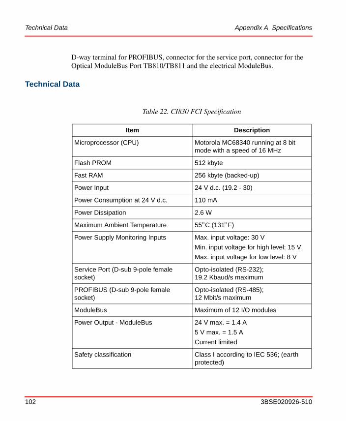
Technical Data Appendix A Specifications
102 3BSE020926-510
D-way terminal for PROFIBUS, connector for the service port, connector for the Optical ModuleBus Port TB810/TB811 and the electrical ModuleBus.
Technical Data
Table 22. CI830 FCI Specification
Item Description
Microprocessor (CPU) Motorola MC68340 running at 8 bit mode with a speed of 16 MHz
Flash PROM 512 kbyte
Fast RAM 256 kbyte (backed-up)
Power Input 24 V d.c. (19.2 - 30)
Power Consumption at 24 V d.c. 110 mA
Power Dissipation 2.6 W
Maximum Ambient Temperature 55°C (131°F)
Power Supply Monitoring Inputs Max. input voltage: 30 V
Min. input voltage for high level: 15 V
Max. input voltage for low level: 8 V
Service Port (D-sub 9-pole female socket)
Opto-isolated (RS-232);19.2 Kbaud/s maximum
PROFIBUS (D-sub 9-pole female socket)
Opto-isolated (RS-485);12 Mbit/s maximum
ModuleBus Maximum of 12 I/O modules
Power Output - ModuleBus 24 V max. = 1.4 A
5 V max. = 1.5 A
Current limited
Safety classification Class I according to IEC 536; (earth protected)

Appendix A Specifications Technical Data
3BSE020926-510 103
Protection rating IP20 according to IEC 529, (IEC 144)
Rated insulation voltage 50 V
Dielectric test voltage 500 V a.c.
Acceptable wire sizes 0.25 - 2.5mm2, 24 - 14 AWG
Recommended torque: 0.5 - 0.6 Nm
Stripping length: 6-7.5 mm, 0.24-0.30 in
Width 84 mm (3.3”)
Depth 122 mm (4.8”)
Height 170 mm (6.7”) including latch
Weight 0.45 kg (1.0 lb.)
Table 22. CI830 FCI Specification (Continued)
Item Description

Dimensions Appendix A Specifications
104 3BSE020926-510
Dimensions
Connections
Figure 30. CI830 FCI Dimensions
Table 23. Power Supply Connections (XI)
Pin Designation Description
4 L+ +24 V d.c. Supply
3 L- 0 V d.c. Supply
2 SA Redundant Power Supply “A” Monitoring Input
1 SB Redundant Power Supply “B” Monitoring Input

Appendix A Specifications Connections
3BSE020926-510 105
Table 24. Service Port (X3)
Pin Designation Description
1
2 TD Transmit Data channel B
3 RD Receive Data channel B
4
5 SG Signal Ground
6
7 RDA Receive Data channel A (for debugging only)
8 TDA Transmit Data channel A (for debugging only)
9
Table 25. FCI PROFIBUS Connections (X2)
Pin Designation Description
1 Shield Shield/protective ground
2 - Not used
3 RxD/TxD-P Receive/Transmit data - plus
4 - Not used
5 DGND Data ground
6 VP Supply voltage for the terminating resistors
7 - Not used

Connections Appendix A Specifications
106 3BSE020926-510
8 RxD/TxD-N Receive/Transmit data - minus
9 - Not used
Table 25. FCI PROFIBUS Connections (X2) (Continued)
Pin Designation Description

Appendix A Specifications Block Diagram CI830
3BSE020926-510 107
Block Diagram CI830
DC
DC
DC
DC
POWOKD+,D-
POS(9:0)
+24V0V24
0V+5V
BATOK
SB
SA
L-
L+
F(ault)
STN.
R(un)P(owok)
TxRx
ADDR
Current
X9
X3
X1
4
3
1
2
Electrical ModuleBus
Service Port
Fiber Optical EO
EO TX
RX
DIN-rail
CLK+,CLK-
RxD/TxD-N
RxD/TxD-P
VP
8
3
6
5
X2
SHIELD 1
DGNDPROFIBUS Connector
DDCC+
MC68340
FLASH
GLUESPC4
Reset logic,
+5 V Supervision
RS-485
RS-485
RS-485
+5 V
0 V
0 V 0 V
0 V0 V
+5 V+5 V
+5 V+5 V
+5 V
0 V
IRQ
7-N
RAM
ModuleBus Module
DSUB9
Connector
Connector
Limit

CI840 Fieldbus Communications Interface (FCI) Appendix A Specifications
108 3BSE020926-510
CI840 Fieldbus Communications Interface (FCI)
Features
• PROFIBUS-DPV1 fieldbus interface.
• Supervisory functions of I/O ModuleBus.
• Isolated power supply to I/O modules.
• OSP handling and configuration.
• Input power fused.
• Hot Configuration In Run.
• HART pass-through.
Description
The CI840 Fieldbus Communications Interface (FCI) is an intelligent communication interface between a Controller via the PROFIBUS-DPV1 fieldbus and the S800 I/O modules via the ModuleBus.
CI840 is designed to be used in redundant applications.
CI840 contains one PROFIBUS-DPV1 interface, two electrical ModuleBus interfaces, LED indicators and a opto-isolated RS232 service port.
CI840 has isolated power converters that generates internal power for CI840 and current limited +5 V supply for two electrical ModuleBuses.
Besides +5 V CI840 also distribute a current limited 24 V for the two ModuleBuses.
CI840 must be mounted on a Module Termination Unit TU846 or TU847. With CI840 mounted on a TU847, only one electrical ModuleBus is connected. When mounted on a TU846, two electrical ModuleBuses are connected.
CI840
FR
PRIM
PRx/Tx
DUAL

Appendix A Specifications Description
3BSE020926-510 109
The Module Termination unit is DIN-rail mounted and grounded to the DIN-rail. The Module Termination Unit TU847 carries screw terminals for power supply and redundant power supply monitoring, two D-way terminals for PROFIBUS, two connectors for the service ports, one connector for the Optical ModuleBus Port TB842, mounted on TB806, and one electrical ModuleBus.
The Module Termination Unit TU846 carries screw terminals for power supply and redundant power supply monitoring, two D-way terminals for PROFIBUS, two connectors for the service ports, two connectors for the Optical ModuleBus Port TB842, mounted on TB846, and two electrical ModuleBuses.

Description Appendix A Specifications
110 3BSE020926-510
Figure 31. CI840 and TU847
CI840
FR
PRIM
PRx/Tx
DUAL
CI840
FR
PRIM
PRx/Tx
DUAL

Appendix A Specifications Technical Data
3BSE020926-510 111
Technical Data
Table 26. CI840 FCI Specification
Item Description
Microprocessor (CPU) Motorola MCF5307 with a speed of 64 MHz
Flash PROM 1 Mbyte
Fast RAM 8 Mbyte
Power Input 24 V d.c. (19.2 - 30)
Power Input Fuse 2 AF
Power Consumption at 24 V d.c. 190 mA
Power Dissipation 7.7 W
Maximum Ambient Temperature 55°C (131°F) horizontal mounted40°C (104°F) vertical mounted
Power Supply Monitoring Inputs Max. input voltage: 30 V
Min. input voltage for high level: 15 V
Max. input voltage for low level: 8 V
Service Port (RJ 45 connector on TU847)
Opto-isolated (RS-232);19.2 Kbaud/s maximum
PROFIBUS (D-sub 9-pole female socket)
Opto-isolated (RS-485);12 Mbit/s maximum
ModuleBus Maximum of 12 I/O modules
Power Output - ModuleBus 24 V max. = 1.4 A
5 V max. = 1.5 A
Current limited
Switch over time at failure in a redundant CI840 unit
Typical <100 ms
Maximum 150 ms

Connections Appendix A Specifications
112 3BSE020926-510
Connections
See Connections on page 124.
Switch over time at communication error on Profibus used by primary CI840
Typical < Watchdog Time(1) + 50ms +(6 * Profibus cycle time)
Time to OSP in case of communication error on Profibus
Single FCI: Watchdog Time(1) +(2 * Modulebus cycle time)
Redundant FCI: Watchdog Time(1) + Output Hold Time +(2 * Modulebus cycle time)
MTU Keying code AA
Safety classification Class I according to IEC 536; (earth protected)
Protection rating IP20 according to IEC 529, (IEC 144)
Rated insulation voltage 50 V
Dielectric test voltage 500 V a.c.
Acceptable wire sizes 0.25 - 2.5mm2, 24 - 14AWG,
Recommended torque: 0.5 - 0.6 Nm
Stripping length: 6 - 7.5 mm, 0.24 - 0.30 in
Width 54 mm (2.13”)
Depth 96 mm (3.78”)
Height 119 mm (4.69”)
Weight 0.2 kg (0.44 lb.)
(1) Watchdog Time is set by the Profibus master.
Table 26. CI840 FCI Specification (Continued)
Item Description

Appendix A Specifications Block Diagram CI840, single ModuleBus
3BSE020926-510 113
Block Diagram CI840, single ModuleBus
Figure 32. Block Diagram CI840, single ModuleBus

Block Diagram CI840, dual ModuleBus Appendix A Specifications
114 3BSE020926-510
Block Diagram CI840, dual ModuleBus
Figure 33. Block Diagram CI840, dual ModuleBus
M
OD
ULEB
US A
M
OD
ULEB
US B
+5V_A
CI840 TB846
POWOKA +5V A
+24V_A
POWOKB +5V B
+24V_B
RTS +5V P 0V_P
TB842 A TXA
RXA
POWA
TXB RXB
POWB
POWOKA +5V A
+24V_A
POWOKB +5V B
+24V_B
RTS +5V P 0V_P
TXA RXA
POW_A
TXB RXB
POW_B
TB842 B
Electrical Modulebus A
Electrical Modulebus B
Profibus A
Service A
POW
ER
PBA
PBB
SERV
.A
SERV
.B
5V_B
5V
_A
STATION ADDRESS
CI840
Stn.address
Power supply
TU846
BLOCK
L+
A/B
-N
0V
+5V
X1 X4A X4B X5A X5B
X3A
X3B
X2B
X2A
POS6-0
POS6-0
L+
MTU
_SEL
+5V
Optical module bus
+5V_B
BLOCK
SYN
C
FCL1
FCL2
A/B
-N
+5V
MTU
_SEL
+5V
SHU
TDA
SHU
TDB

Appendix A Specifications TU846 Redundant MTU for CI840, dual ModuleBus
3BSE020926-510 115
TU846 Redundant MTU for CI840, dual ModuleBus
Features
• Power supply connection.
• Two PROFIBUS connections.
• Two service tool connections.
• Two rotary switch for station address setting.
• Connection for two ModuleBuses.
• Connector for ModuleBus Optical Port.
• Mechanical keying prevents insertion of the wrong module type.
• Latching device to DIN rail for locking and grounding.
• DIN rail mounted.
Description
The TU846 is a module termination unit (MTU) for redundant configuration of the field communication interface CI840 and redundant I/O.
The MTU is a passive unit having connections for power supply, two electrical ModuleBuses, two CI840 and two rotary switches for station address (0 to 99) settings.
A ModuleBus Optical Port TB842 can be connected to TU846 via TB846.
Four mechanical keys, two for each position, are used to configured the MTU for the right types of modules. Each key has six positions, which gives a total number of 36 different configurations. The configurations can be changed with a screwdriver.

Technical Data Appendix A Specifications
116 3BSE020926-510
The MTU can be mounted on a standard DIN rail. It has a mechanical latch that locks the MTU to the DIN rail. The latch can be locked/unlocked with a screwdriver.
The MTU has two BLOCK signals, one for each module position, that keeps the modules in its init state until it is locked in its position.
Technical Data
Table 27. TU846 Redundant MTU for CI840
Item Value
Power input 24 V d.c. (19.2 - 30 V)
PROFIBUS connection DSUB9 connector
Service ports RJ45 connector
ModuleBus current distributionMaximum 5 VMaximum 24 V
1.5 A1.5 A
Mechanical keys (2) 36 different combinations
Safety Classification Class I according to IEC 536; (earth protected)
Protection Rating IP20 according to IEC 529, (IEC 144)
Rated insulation voltage 50 V
Dielectric test voltage 500 V a.c.
Width 124 mm (4.88”)
Acceptable wire sizes 0.25 - 2.5mm2, 24 - 14 AWG
Recommended torque: 0.5 - 0.6 Nm
Stripping length: 6-7.5 mm, 0.24-0.30 in
Depth 47 mm (1.85”)

Appendix A Specifications Dimensions
3BSE020926-510 117
Dimensions
Height 186 mm (7.32”) including latch
Weight 0.5 kg (1.1 lbs.)
Figure 34. Dimensions TU846
Table 27. TU846 Redundant MTU for CI840 (Continued)
Item Value

Connections Appendix A Specifications
118 3BSE020926-510
Connections
Table 28. TU846 Power Supply Connections
Designation Description
L+ +24 V d.c. Supply In
L- 0 V d.c. Supply In
SA Redundant Power Supply “A” Monitoring Input
SB Redundant Power Supply “B” Monitoring Input
Table 29. PROFIBUS Connector Pin-out
Pin Designation Description
1 Shield Shield/protective ground
2 NC Not used
3 RxD/TxD-P Receive data/transmit data positive
4 RTS Direction control (optional)
5 DGND Data ground
6 VP Supply of termination resistance (5V)
7 NC Not used
8 RxD/TxD-N Receive data/transmit data negative
9 DGND Data ground (if RTS is used)
Table 30. Service Port Connector Pin-out
Pin Designation Description
1 NC Not used
2 NC Not used
3 Tx Transmitted data

Appendix A Specifications Connections
3BSE020926-510 119
4 GND Signal ground
5 GND Signal ground
6 Rx Receive data
7 NC Not used
8 NC Not used
Table 30. Service Port Connector Pin-out (Continued)
Pin Designation Description

Block Diagram TU846 Appendix A Specifications
120 3BSE020926-510
Block Diagram TU846
Figure 35. Block Diagram TU846
M
OD
ULEB
US A
M
OD
ULEB
US B
+5V_A
CI840 TB846
POWOKA +5V A
+24V_A
POWOKB +5V B
+24V_B
RTS +5V P 0V_P
TB842 A TXA
RXA
POWA
TXB RXB
POWB
POWOKA +5V A
+24V_A
POWOKB +5V B
+24V_B
RTS +5V P 0V_P
TXA RXA
POW_A
TXB RXB
POW_B
TB842 B
Electrical Modulebus A
Electrical Modulebus B
Profibus A
Service A
POW
ER
PBA
PBB
SERV
.A
SERV
.B
5V_B
5V
_A
STATION ADDRESS
CI840
Stn.address
Power supply
TU846
BLOCK
L+
A/B
-N
0V
+5V
X1 X4A X4B X5A X5B
X3A
X3B
X2B
X2A
POS6-0
POS6-0
L+
MTU
_SEL
+5V
Optical module bus
+5V_B
BLOCK
SYN
C
FCL1
FCL2
A/B
-N
+5V
MTU
_SEL
+5V
SHU
TDA
SHU
TDB

Appendix A Specifications TU847 Redundant MTU for CI840, single ModuleBus
3BSE020926-510 121
TU847 Redundant MTU for CI840, single ModuleBus
Features
• Power supply connection.
• Two PROFIBUS connections.
• Two service tool connections.
• Two rotary switch for station address setting.
• ModuleBus connections.
• Connector for ModuleBus Optical Port.
• Mechanical keying prevents insertion of the wrong module type.
• Latching device to DIN rail for locking and grounding.
• DIN rail mounted.
Description
The TU847 is a module termination unit (MTU) for redundant configuration of the field communication interface CI840.
The MTU is a passive unit having connections for power supply, electrical ModuleBus, two CI840 and two rotary switches for station address (0 to 99) settings.
A ModuleBus Optical Port TB842 can be connected to TU847 via TB806.
Four mechanical keys, two for each position, are used to configured the MTU for the right types of modules. Each key has six positions, which gives a total number of 36 different configurations. The configurations can be changed with a screwdriver.
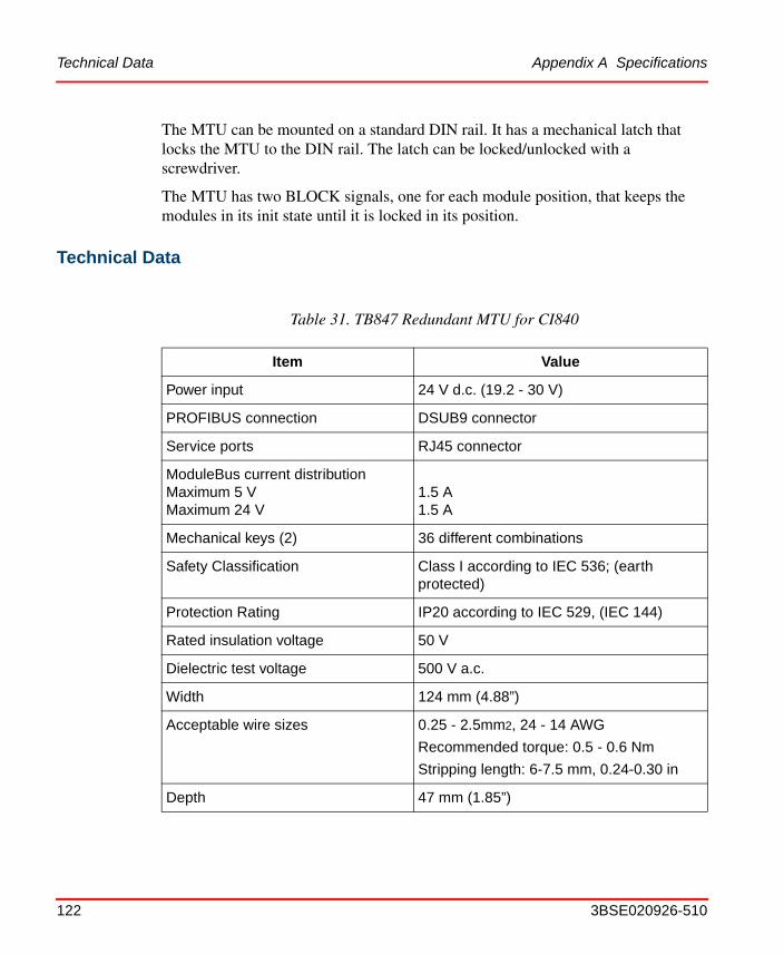
Technical Data Appendix A Specifications
122 3BSE020926-510
The MTU can be mounted on a standard DIN rail. It has a mechanical latch that locks the MTU to the DIN rail. The latch can be locked/unlocked with a screwdriver.
The MTU has two BLOCK signals, one for each module position, that keeps the modules in its init state until it is locked in its position.
Technical Data
Table 31. TB847 Redundant MTU for CI840
Item Value
Power input 24 V d.c. (19.2 - 30 V)
PROFIBUS connection DSUB9 connector
Service ports RJ45 connector
ModuleBus current distributionMaximum 5 VMaximum 24 V
1.5 A1.5 A
Mechanical keys (2) 36 different combinations
Safety Classification Class I according to IEC 536; (earth protected)
Protection Rating IP20 according to IEC 529, (IEC 144)
Rated insulation voltage 50 V
Dielectric test voltage 500 V a.c.
Width 124 mm (4.88”)
Acceptable wire sizes 0.25 - 2.5mm2, 24 - 14 AWG
Recommended torque: 0.5 - 0.6 Nm
Stripping length: 6-7.5 mm, 0.24-0.30 in
Depth 47 mm (1.85”)
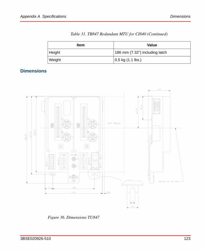
Appendix A Specifications Dimensions
3BSE020926-510 123
Dimensions
Height 186 mm (7.32”) including latch
Weight 0.5 kg (1.1 lbs.)
Figure 36. Dimensions TU847
Table 31. TB847 Redundant MTU for CI840 (Continued)
Item Value

Connections Appendix A Specifications
124 3BSE020926-510
Connections
Table 32. TU847 Power Supply Connections
Designation Description
L+ +24 V d.c. Supply In
L- 0 V d.c. Supply In
SA Redundant Power Supply “A” Monitoring Input
SB Redundant Power Supply “B” Monitoring Input
Table 33. PROFIBUS Connector Pin-out
Pin Designation Description
1 Shield Shield/protective ground
2 NC Not used
3 RxD/TxD-P Receive data/transmit data positive
4 RTS Direction control (optional)
5 DGND Data ground
6 VP Supply of termination resistance (5V)
7 NC Not used
8 RxD/TxD-N Receive data/transmit data negative
9 DGND Data ground (if RTS is used)
Table 34. Service Port Connector Pin-out
Pin Designation Description
1 NC Not used
2 NC Not used
3 Tx Transmitted data

Appendix A Specifications Connections
3BSE020926-510 125
4 GND Signal ground
5 GND Signal ground
6 Rx Receive data
7 NC Not used
8 NC Not used
Table 34. Service Port Connector Pin-out (Continued)
Pin Designation Description

Block Diagram TU847 Appendix A Specifications
126 3BSE020926-510
Block Diagram TU847
Figure 37. Block Diagram TU847

3BSE020926-510 127
CCI830 16, 19, 22, 81 to 82, 84, 89Connections
Power supply 34, 37, 41PROFIBUS-DP 32, 35, 39
DData scanning principles 66
EError state 70
FFCI 12, 16, 19, 22, 63, 81 to 82, 95, 101, 108FCI module 17, 20, 22Fieldbus communications interface 95, 101, 108
II/O module functionality
PROFIBUS-DP 67I/O station 13Init state 69
LLEDs
FCI 73, 75, 77
NNot configured state 69
OOperational state 69OSP 71OSP state 70
PParameters
Loading 71Loading invalid 71Non-volatile 71
PROFIBUS-DP 13, 16, 19, 22, 63I/O module functionality 67
RReady state 69
SState
Error 70Init 69Not configured 69Operational 69OSP (Outputs Set as Predefined) 70Ready 69
Station address selectorPROFIBUS-DP 31, 35, 38
INDEX

Index
128 3BSE020926-510
Index
128 3BSE020926-510


Copyright © 2003-2010 by ABB.All Rights Reserved
ABB AB Control SystemsVästerås, SwedenPhone: +46 (0) 21 32 50 00Fax: +46 (0) 21 13 78 45E-Mail: [email protected]/controlsystems
ABB Industry Pte LtdControl SystemsSingaporePhone: +65 6776 5711Fax: +65 6778 0222E-Mail: [email protected]/controlsystems
ABB Automation GmbHControl SystemsMannheim, GermanyPhone: +49 1805 26 67 76Fax: +49 1805 77 63 29E-Mail: [email protected]/controlsystems
ABB Inc.Control SystemsWickliffe, Ohio, USAPhone: +1 440 585 8500Fax: +1 440 585 8756E-Mail: [email protected]/controlsystems
Power and productivityfor a better worldTM
Contact us
3BS
E02
0926
-510


![Profibus PA Fieldbus Display [ Revision 2 ] and Fieldbus ... Instruments... · Profibus PA Fieldbus Display [ Revision 2 ] and Fieldbus Indicator Fieldbus Interface Guide. ... Siemens](https://img.dokumen.tips/doc/110x75/5b2fe38e7f8b9ae16e8da83d/profibus-pa-fieldbus-display-revision-2-and-fieldbus-instruments.jpg)