Embed Size (px)
Citation preview

REPLACEMENT GUIDE
38-00001-02
Fire and Smoke Damper Actuator Field Replacement Guide
APPLICATIONSafety should never be left to chance. Honeywell fire and smoke actuators are designed to meet both UL-555 and UL555S 350°F safety requirements for fire and smoke applications, if applicable. Fast-acting actuators close dampers in 15 seconds, and the integral spring return ensures the consistent, proper level of torque. For the highest level of occupant safety, you can count on Honeywell.
Fire and Smoke actuators and assemblies must function properly during a fire or life-safety emergency. Honeywell Fire and Smoke Actuators provide fast action when timeliness is key in preventing the spread of fire and smoke. Proper installation and periodic performance testing are required to ensure fire and smoke damper assemblies will fully function should an emergency occur.
The following guidelines are crucial to keep fire and smoke damper assemblies operating properly, and to stay in adherence to standards and codes.
FIRE CODE REFERENCES AND INFORMATIONHoneywell Fire and Smoke Actuators are designed to meet both UL555 and UL555S safety requirements for combined fire and smoke applications, if applicable.
The following maintenance guidelines are a summary of the National Fire Protection Association (NFPA) Codes as well as Air Movement and Control Association (AMCA) and Honeywell manuals. We recommend that you become familiar with NFPA 80, 90A, 92A & B, and 105 and AMCA publication 503. Be aware that other codes, such, International Building Code (IBC), regional, state and local codes, may also apply to your area.
REPLACEMENT GUIDELINES
Actuator SpecificationsUL555 and UL555S require fire and smoke actuators to be tested to 20,000 close and reopen cycles and close within 75 seconds. UL555 also requires them to be rated to either 250°F or 350°F. If UL does not apply to your region, please omit.
Honeywell fire and smoke actuators are rated to 30,000 cycles, operate within 15 seconds, and are rated to 350°F.
ApplicationsCombined Fire and smoke dampers are used to maintain fire barrier ratings when walls and floors are penetrated by ductwork.
Smoke dampers are used to prevent the passage of smoke through the HVAC system or from one side of a fire-rated separation to the other. They may be dedicated to this function or also function as HVAC dampers.

FIRE AND SMOKE DAMPER ACTUATOR FIELD REPLACEMENT GUIDE
38-00001—02 2
Damper Manufacturer’s GuidelinesWhen replacing actuators, it is important to follow the guidelines that are provided by the damper manufacturer for the damper assembly. When replacing a fire and smoke actuator the replacement should be either like-for-like with the original, factory-mounted actuator, or a technically superior product where the total assembly has passed UL testing with the damper manufacturer.
Please refer to the damper manufacturer’s guidelines for details.
MAINTENANCE INFORMATIONFire and Smoke damper assemblies must undergo periodic performance testing to be properly maintained and to ensure they are functioning and will function in a fire or life-safety emergency.
The NFPA codes require combined fire and smoke dampers be tested and inspected at the time the system is commissioned, after it has been balanced, and one year after installation. Then they need to be tested and inspected every 4 years, except in hospitals, where they need to be tested and inspected every 6 years. See "Option 1” and “Option 2” in this section for detailed test instructions.
AMCA suggests that smoke dampers be tested at least semi-annually. Smoke dampers should be operated, and the correct outputs should be observed, to verify operation. These tests need to also be conducted under standby power, if used.
Honeywell Fire and Smoke Actuators are found in combination fire and smoke damper assemblies that use a bi-metallic disc type thermostat to interrupt electrical power to the actuator at a specified temperature. Once the specified temperature is reached, power will be interrupted and the spring return of the actuator will close the damper. When these actuators are used in smoke damper applications, they are usually controlled by smoke detectors or fire alarms.
Periodic inspection includes:1. Verify that there is full unobstructed access to the
damper2. Test the damper with normal HVAC airflow and verify
that it opens following either Option 1 or Option 2. There should be no interference due to rust, dam-aged frame or blades, or other moving parts.
Option 1: Dampers with Position Indication Wired to indication Lights, or Control Panels:
Switches can be wired to local or remote control panels or building automation systems (BAS) to indicate that the damper is in the fully-open position, fully-closed position, or neither.
a. Use the signal from the damper’s position indi-cation device to confirm that the damper is in the fully-open position.
b. Remove electrical power or air pressure from the actuator to allow the actuator’s spring return fea-ture to close the damper.
c. Use the signal from the damper’s position indi-cation device to confirm that the damper reaches its fully-closed position.
d. Re-apply electrical power to re-open the damper.e. Use the signal from the damper’s position indi-
cation device to confirm the damper reaches its fully-open position.
Option 2: Dampers without position indication:a. Visually confirm that the damper is fully-open
position.b. Ensure that all obstructions, including hands,
are out of the path of the damper blades.c. Remove electrical power or air pressure from the
actuator to allow the actuator’s spring return fea-ture to close the damper.
d. Visually confirm that the damper closes com-pletely.
e. Re-apply electrical power to re-open the damper.f. Visually confirm that the damper is in the fully
open position.
3. If the damper is not operable, it must be repaired as soon as possible. If the actuator has failed, replace it with a UL approved actuator if required. See Table 1. See Figs. 2-3 for mounting and installation informa-tion and Figs. 4-9 for wiring. After these repairs, the damper should be tested again.
4. If there is a latch, verify that it is operable.5. Perform any other damper manufacture recom-
mended maintenance such as lubrication.6. Following the test and any repairs, document the
location of the damper, the date, the inspector, and deficiencies or repairs. Keep the record for the life of the damper, and have it available as you may need to show it to an inspector.
Fig. 1. Typical Fire and Smoke Damper Assembly.
Source: AMCA International: Guide for Commissioning and Periodic Performance Testing of Fire, Smoke, and other Life Safety Related Dampers, 2012.

FIRE AND SMOKE DAMPER ACTUATOR FIELD REPLACEMENT GUIDE
3 38-00001—02
PRODUCT INFORMATION
Table 1. Fire and Smoke Cross Reference.
TorqueModel
Number VoltageSPST
Aux SwitchLegacy
HoneywellBelimoCross
Siemens Cross
30 lb-in (3.4 Nm)
MS4104F1010
120 Vac 0 ML4115A1009ML4115A1017ML4115B1008ML4115B1016ML4115H1002ML4115J1009ML4202F1000ML4302F1008
FSLF120 US None
MS4104F1210 120 Vac 2 Internal None FSLF120-S US None
MS4604F1010 230 Vac 0 ML4115C1007ML4115C1015ML4115D1006ML4115D1014ML4702F1009ML4802F1007
FSLF230 US None
MS4604F1210 230 Vac 2 Internal None FSLF230-S US None
MS8104F1010 24 Vac 0 ML8115A1005ML8115A1013ML8115B1004ML8115B1012ML8115H1008ML8115J1005ML8202F1006ML8302F1004
FSLF24 US None
MS8104F210 24 Vac 2 Internal None FSLF24-S US None
80 lb-in (9 Nm) MS4109F1010 120 Vac 0 MS4209F1007MS4309F1005
FSNF120 US GND221.1U
MS4109F1210 120 Vac 2 Internal None FSNF120-S US GND226.1U
MS4609F1010 230 Vac 0 MS4709F1014MS4809F1012
FSNF230 US GND321.1U
MS4609F1210 230 Vac 2 Internal None FSNF230-S US GND326.1U
MS8109F1010 24 Vac 0 MS8209F1003MS8309F1001
FSNF24 US GND121.1U
MS8109F1210 24 Vac 2 Internal None FSNF24-S US GND126.1U
175 lb-in (20 Nm)
MS4120F1006 120 Vac 0 None FSAF120 US GGD221.1U
MS4120F1204 120 Vac 2 Internal None FSAF120-S US None
MS4620F1005 230 Vac 0 None FSAF230 US GGD321.1U
MS4620F1203 230 Vac 2 Internal None FSAF230-S US None
MS8120F1002 24 Vac 0 None FSAF24 US GGD121.1U
MS8120F1200 24 Vac 2 Internal None FSAF24-S US None
FIRE AND SMOKE DAMPER ACTUATOR FIELD REPLACEMENT GUIDE
38-00001—02 4
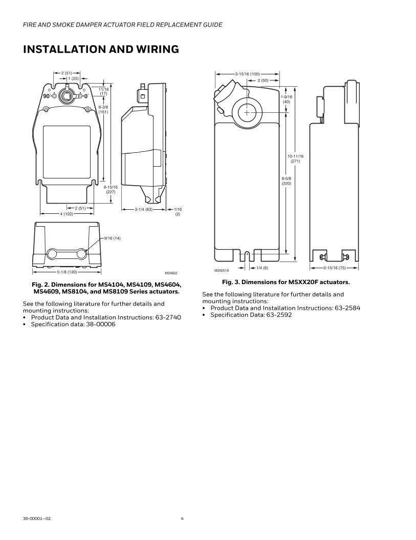
INSTALLATION AND WIRING
Fig. 2. Dimensions for MS4104, MS4109, MS4604, MS4609, MS8104, and MS8109 Series actuators.
See the following literature for further details and mounting instructions:• Product Data and Installation Instructions: 63-2740• Specification data: 38-00006
Fig. 3. Dimensions for MSXX20F actuators.
See the following literature for further details and mounting instructions:• Product Data and Installation Instructions: 63-2584• Specification Data: 63-2592
M34622
2 (51)
1 (25)
90° 0°
11/16(17)
6-3/8(161)
8-15/16(227)
4 (102)2 (51) 1/16
(2)3-1/4 (83)
5-1/8 (130)
9/16 (14)
10-11/16(271)
1-9/16(40)
8-5/8(220)
2 (50)
3-15/16 (100)
2-15/16 (75)1/4 (6)M20051A

FIRE AND SMOKE DAMPER ACTUATOR FIELD REPLACEMENT GUIDE
5 38-00001—02
Wiring
For 30 lb-in and 80 lb-in (3.4 Nm, 9 Nm) models:
Fig. 4. Typical 24 Vac wiring.
Fig. 5. Typical 120 Vac wiring.
Fig. 6. Typical 230 Vac wiring.
For 175 lb-in (20 Nm) models:
Fig. 7. Typical 24 Vac wiring
Fig. 8. Typical 120 Vac wiring.
Fig. 9. Typical 230 Vac wiring.
M34624
24 VAC
BLACK
RED
L1 ( )
L2 ( )
YELLOW
YELLOW
BLUE7° AUXILIARY
SWITCH
85° AUXILIARYSWITCH
BLUE
WHITE
BLACK
GREENL1 ( )
L2 ( )
YELLOW
YELLOW
BLUE
BLUE7° AUXILIARY
SWITCH
85° AUXILIARYSWITCH
120 VAC
M34625
M34626
BLUE
BROWN
GREEN
230 VAC
L1 ( )
L2 ( )
YELLOW
YELLOW
BLUE
BLUE7° AUXILIARY
SWITCH
85° AUXILIARYSWITCH
M20053B
24 VAC
BLACK
RED
GREEN
MS8120F
L1 ( )
L2 ( )
YELLOW
YELLOW
BLUE7° AUXILIARY
SWITCH
85° AUXILIARYSWITCH
BLUE
M20056B
WHITE
BLACK
GREEN
MS4120F
L1 ( )
L2 ( )
YELLOW
YELLOW
BLUE
BLUE7° AUXILIARY
SWITCH
85° AUXILIARYSWITCH
120 VAC
M20057B
BLUE
BROWN
GREEN
230 VAC
MS4620F
L1 ( )
L2 ( )
YELLOW
YELLOW
BLUE
BLUE7° AUXILIARY
SWITCH
85° AUXILIARYSWITCH

FIRE AND SMOKE DAMPER ACTUATOR FIELD REPLACEMENT GUIDE
38-00001—02 6

FIRE AND SMOKE DAMPER ACTUATOR FIELD REPLACEMENT GUIDE
7 38-00001—02

FIRE AND SMOKE DAMPER ACTUATOR FIELD REPLACEMENT GUIDE
Home and Building TechnologiesIn the U.S.:
Honeywell
1985 Douglas Drive North
Golden Valley, MN 55422-3992
customer.honeywell.com
® U.S. Registered Trademark© 2016 Honeywell International Inc.38-00001—02 M.S. Rev. 11-16Printed in United States
By using this Honeywell literature, you agree that Honeywell will have no liability for any damages arising out of your use or modification to, the literature. You will defend and indemnify Honeywell, its affiliates and subsidiaries, from and against any liability, cost, or damages, including attorneys’ fees, arising out of, or resulting from, any modification to the literature by you.