Embed Size (px)
Citation preview
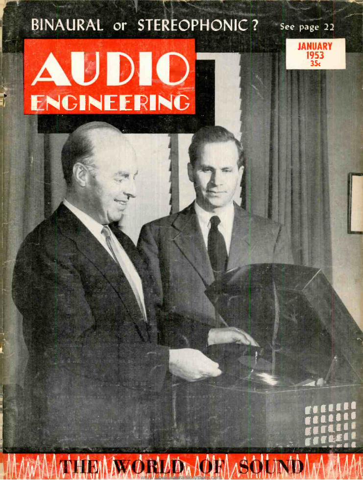
BINAURAL or STEREOPHONIC ? See page 22
JANUARY 1953 35c
ENGINEERING
www.americanradiohistory.comAmericanRadioHistory.Com
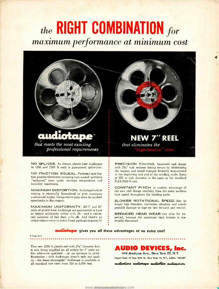
the RIGHT COMBINATION for maximum performance at minimum cost
CUICULOtaPe G
that meets the most exacting professional requirements
NO SPLICES. As always, plastic -base Audiotape in 1200 and 2500 ft reels is guaranteed splice -free.
NO FRICTION SQUEAL. Perfected anti -fric. tion process eliminates annoying tape squeal -prevents "tackiness" even under extreme temperature and humidity conditions.
MINIMUM DISTORTION. Audiotape's oxide coating is especially formulated to give maximum undistorted output. Comparative tests show its marked superiority in this respect.
MAXIMUM UNI FORM I TY. A117" and 10" reels of plastic -base Audiotape are guaranteed to have an output uniformity within ±' db - and a reel -to- reel variation of less than _Ys db. And there's an actual output curve in every 5 -reel package to prove it!
* Trade Marl
PRECISION TIMING. Improved reel design with 23/4" hub reduces timing errors by eliminating the tension and speed changes formerly encountered at the beginning and end of the winding cycle. Ratio of OD to hub diameter is the same as the standard NAB 2500 ft reel.
CONSTANT PITCH is another advantage of the new reel design resulting from the more uniform tape speed throughout the winding cycle.
SLOWER ROTATIONAL SPEED, due to larger hub diameter, minimizes vibration and avoids possible damage to tape on fast forward and rewind.
REDUCED HEAD WEAR can also be ex- pected, because the maximum tape tension is ma- terially decreased.
audiotape gives you all these advantages at no extra cost!
This new 1200 ft plastic reel with 23/4" diameter hub is now being supplied on all orders for 7" reels un- less otherwise specified ... at no increase in price. Remember - with Audiotape, there's only one qual- ity- the finest obtainable! Audiotape is available in all standard size reels from 150 to 5,000 feet.
AUDIO DEVICES, Inc. 444 Madison Ave., New York 22, N.Y.
Export Dept. 13 East 40th St., New York 16, N.Y., Cables "ARLAR"
awdiodiscs aEdiatapo audioflm audiopairrts
f
i+
www.americanradiohistory.comAmericanRadioHistory.Com
Successor to (gXÏ ÏOJ -Established 1917
AUDIO ENGIIIEERIIG
INCLUDING
C. G. McProud, Editor and Publisher Harrie K. Richardson, Associate Editor Edgar M. Villchur, Contributing Editor Eve Drolet, Production Manager Henry A. Schober, Business Manager Edgar E. Newman, Circulation Promotion S. L. Cahn, Advertising Director Elizabeth Beebee, Circulation Manager H. N. Relies, Advertising Manager
Editorial Advisory Board
Howard A. Chinn
John D. Calvin
C. J. LeBel
J. P. Maxfield
George M. Nixon
Representatives
H. Thorpe Covington Special Representative va 677 N. Michigan Ave., Chicago 1 1, Ill. VDR
UMSAU
ecut* $
Sanford R. Cowan, Mid -West Representative 67 W. 44th St., New York 18, N. Y.
West Coast
James C. Galloway J. W. Harbison 816 W. 5th St., Los Angeles 17, Calif.
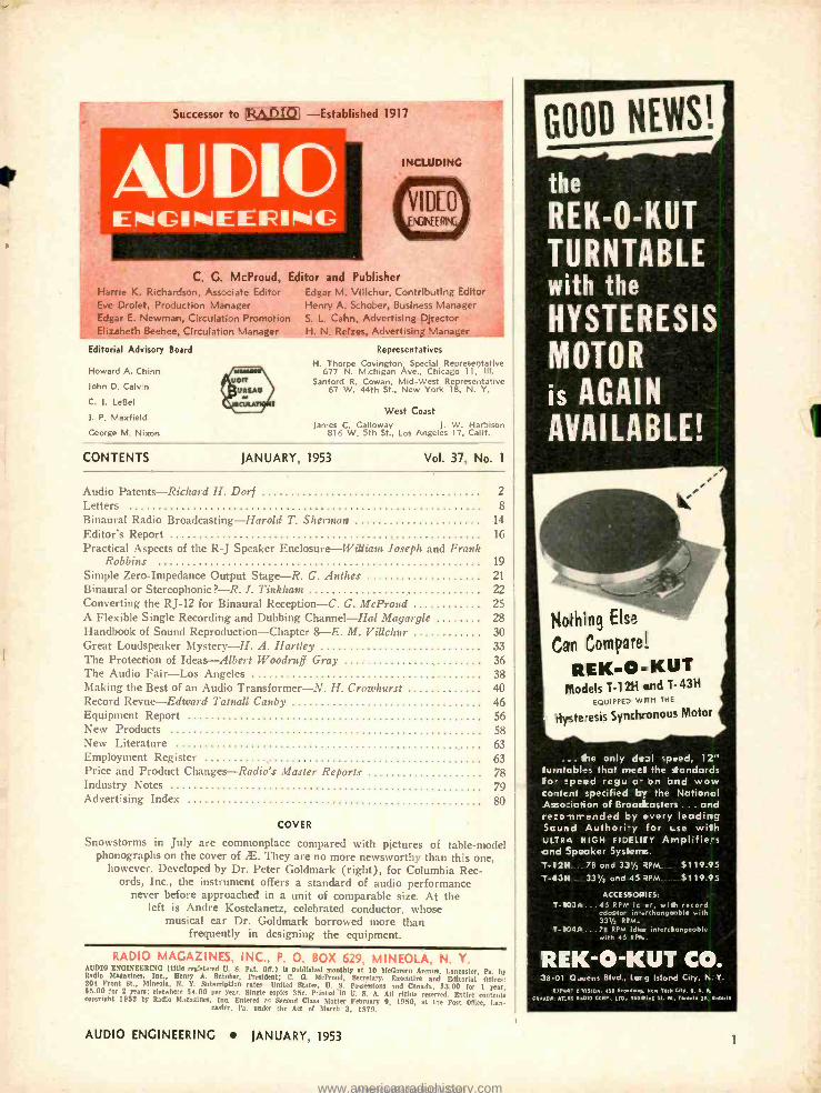
CONTENTS JANUARY, 1953 Vol. 37, No. 1
Audio Patents- Richard H. Dorf 2 Letters 8 Binaural Radio Broadcasting- Harold T. Sherman 14 Editor's Report 16 Practical Aspects of the R -J Speaker Enclosure -William Joseph and Frank
Robbins 19 Simple Zero -Impedance Output Stage -R. G. Anthes 21 Binaural or Stereophonic ? -R. J. Tinkham 22 Converting the RJ -12 for Binaural Reception -C. G. McProud 25 A Flexible Single Recording and Dubbing Channel Hal Magargle 28 Handbook of Sound Reproduction -Chapter 8-E. M. Villchur 30 Great Loudspeaker Mystery -H. A. Hartley 33 The Protection of Ideas -Albert Woodruff Gray 36 The Audio Fair -Los Angeles 38 Making the Best of an Audio Transformer -N. H. Crowhurst 40 Record Revue -Edward Tarnall Canby 46 Equipment Report 56 New Products 58 New Literature 63 Employment Register 63 Price and Product Changes- Radio's Master Reports 78 Industry Notes 79 Advertising Index 80
COVER
Snowstorms in July are commonplace compared with pictures of table -model phonographs on the cover of Æ. They are no more newsworthy than this one,
however. Developed by Dr. Peter Goldmark (right), for Columbia Rec- ords, Inc., the instrument offers a standard of audio performance
never before approached in a unit of comparable size. At the left is Andre Kostelanetz, celebrated conductor, whose
musical ear Dr. Goldmark borrowed more than frequently in designing the equipment.
RADIO MAGAZINES, INC., P. 0. BOX 629, MINEOLA, N. Y. AUDIO ENGINEERING (title registered U. S. Pat. Off.) la published monthly at 10 McGovern Avenue. Lancaster, Pa. by Radio Magazines, hie., Henry A. Schober, President; C. O. McProud, Secretary. Executive and Editorial Offices: 204 Front St., Mineola, N. Y. Subscription rates -United States, U. S. Possessions and Canada, $3.00 for 1 year, $5.00 for 2 years; elsewhere $4.00 per year. Single copies 35c. Printed in U. S. A. All rights reserved. Entire contents copyright 1952 by Radio Magazines, Inc. Entered as Second Class flatter February 9, 1950, at the Post OMlee. Lan -
raster, Pa. under the Act of Starch 3, 1579.
AUDIO ENGINEERING JANUARY, 1953
the
REK -O -KUT TURNTABLE with the
HYSTERESIS MOTOR
is AGAIN AVAILABLE!
Nothing Else
Can Compare!
REK -O -KUT Models T -1211 and T" 43H
EQUIPPED Vo 11H THE
-lysteesis Synrhronou, Motor
...the only diI speed, 12" turntables that meet the standards fo- speed regu a- on and wow content specified by the National Asso :iation of Broadcaster, ... and re:o- nrrended Ey every leading Scund Authori-y for t-se with ULTRA NIGH FIDELIEY Amplifies and Speaker Systerrs. T -12H 78 and 33'/3 RPM $119.95 T-4311 331/3 and 45 RPM $119.95
T-103 A
T-104A
ACCESSORIES: 45 RPM ic or, will, record odoptor i .rchongaoble with 331/2 RPM. 78 RPM idfar interclangeable with 45 RPes.
REK-O-KUT CO. 38-01 Oueens Blvd., Lcrg Island City, N. Y.
E2P.a" O VISION aS1 Brsew. Mew Tor CitT. U. S. A ar_sS M010 CORP . 110- S11Ina St. M. Trrrntr 21, Bntufr
1
www.americanradiohistory.comAmericanRadioHistory.Com
i
Linear and functional output, rugged construction, ball bearings,
small size, low torque, syncro -type mount.
Push -pull motion, linear and Junctional output, high resolution,
rectilinear potentiometer.
Functional and linear outputs, coils independently adjustable,
variety of flexible assemblies.
i"c40i7ae Unear output, minimum torque,
potentiometer and selsyn outputs, most ultra sensitive of them all.
These potentiometers are available in a variety of resistance values
and circuits. For details on these and other fine instruments, write:
G. M. GIANNINI & CO., INC. Pasadena 1, Calif.
2
MAGNETIC RECORDING has certainly come a long way since Poulsen's original methods, and most of the progress
has been made in the last very few years. One of the problems in obtaining good fidelity with wire and tape is the non - linearity of the B -H curve of the medium. That was solved by Poulsen (and until a relatively short time ago) by superimposing a d.c. bias on the sound. But more recently a.c. bias has become standard.
The field is still new enough, however, from the standpoint of concentrated de- velopment and commercialization, to allow the thought that perhaps a.c. supersonic bias may not be the very best bias method. Lawrence H. Connell of Detroit, Mich., proposes a new and unfamiliar system which deserves a good look, at least by those interested in top -quality reproduction. Without experimentation the writer is un- able to even begin to pass judgment on it, but Connell's idea is at least well worth examination. It is explained in his patent No. 2,604,546.
Figure 3 shows a magnetization curve which might represent that of a typical
255 W. 84th St., New York 24, N. Y.
acu
traguiz RICHARD H. DORF'
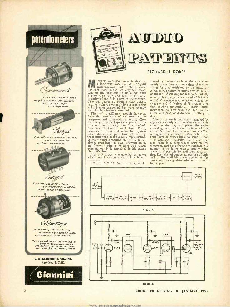
recording medium such as the tape com- monly in use. For various values of magne- tizing force H exhibited by the head, the curve shows values of magnetization B left on the tape. Assuming the tape to be initially unmagnetized, applied values of H between a and a' produce magnetization values be- tween b and b'. Values of H greater than that produce proportionally much larger magnetization. Obviously the steps in the curve will produce distortion if nothing is done.
The distortion is commonly removed by applying a steady a.c. bias which effectively eliminates the step and places the entire recording on the linear portions of the curve. A.c. bias has, however, some effect on higher frequencies ; it either fails to re- cord them or erases them to some extent. It is common knowledge that the correct bias value is a compromise between low distortion and good frequency response, the failings in the latter respect usually being made up if possible by additional equaliza- tion. D.c. bias, of course, allows use of only half of the available linear portion of the curve and the signal -to -noise ratio is rela- tively poor.
INPUT SIGNAL TO REH RECORDED
FIRST AMPLIFIER
LIMITING RESISTOR
RECT. SECOND
AMPLIFIER LIMITING RESISTOR
RECT.
1-070 OUT
MISER STAGE D HEAD
VOL AGE
DIVIDER
Figure 1.
Figure 2
AUDIO ENGINEERING JANUARY, 1953
www.americanradiohistory.comAmericanRadioHistory.Com
Hrïtis/1 Industries Corp.
f
takes pleasure in
offering to discriminating American music listeners, engineers and 'Manufacturers, the finest sound and electronic equipment produce in Great Britain! You may purchase every British
Industries product with
frcon fidence, knowing... That it has been rigorously
Ai tested and the en as the best o ita dd
That ully guarantee
Tharomplete stock of spare components is
maintained throughout the United States
That factory trained British Industries service facilities insure years of excellent performance and your conti ed satisfaction. It
GARRARD WORLD'S FINEST
3 -SPEED AUTOMATIC RECORD PLAYERS
LEAK "POINT ONE"
AUDIO AMPLIFIER AND PRE -AMPLIFIER
with the unique Vari- Slope.Distcrt ion 0.1%1
WHARFEDALE LOUDSPEAKERS
resigned and built under cirection of world renowned engineer G. A.
Briggs
KT66 POWER I AMPLIFYING TUBE
"FINEST AUDIO TUBE
EVER MADE" rchangecble with AmerLcan 6L6)
A Cordial Invitation to visit us at the
Audio Fair in Los Angeles February 5th, 6th, 7th,
Rooms 615 and 618
Morel Alexandria
Whether you are a "user" or a "seller" of sound or electronic equipment, we believe you will find British Industries literature interesting, informative and valuable. Mail this convenient coupon today.
BRITISH INDUSTRIES CORPORATION 164 Duane Street, New York 13, N. Y.
R -1 SPEAKER ENCLOSURES
"MAXIMUM BASS MINIMUM SPACE"
.'Jr ,1!.Ietured In U.S.A.)
ERSIN MULTICORE
3 -CORE SCLDER The my sclder made with eon- corrosi ,re, extra - activa Ersin ro Urs Flux!
AVO "DOUGLAS" &
"MACADIE" COIL WINDERS
Outstanding for rugged - lo ess and versatility
Other Quality British Products, which have found wide acceptance in America through B.I.C.:
SELENIUM RECTIFIERS
GERMANIUM DIODES
EXPANDED ALUMINUM MESH
British Indu =tries Corporation Dept A-1 ¡(.4 Duan Street
1 New York-13 N. Y.
Gentlemen:
Please send illustrated literature to:
L.
Name..........
Address
C ty Zone State
www.americanradiohistory.comAmericanRadioHistory.Com
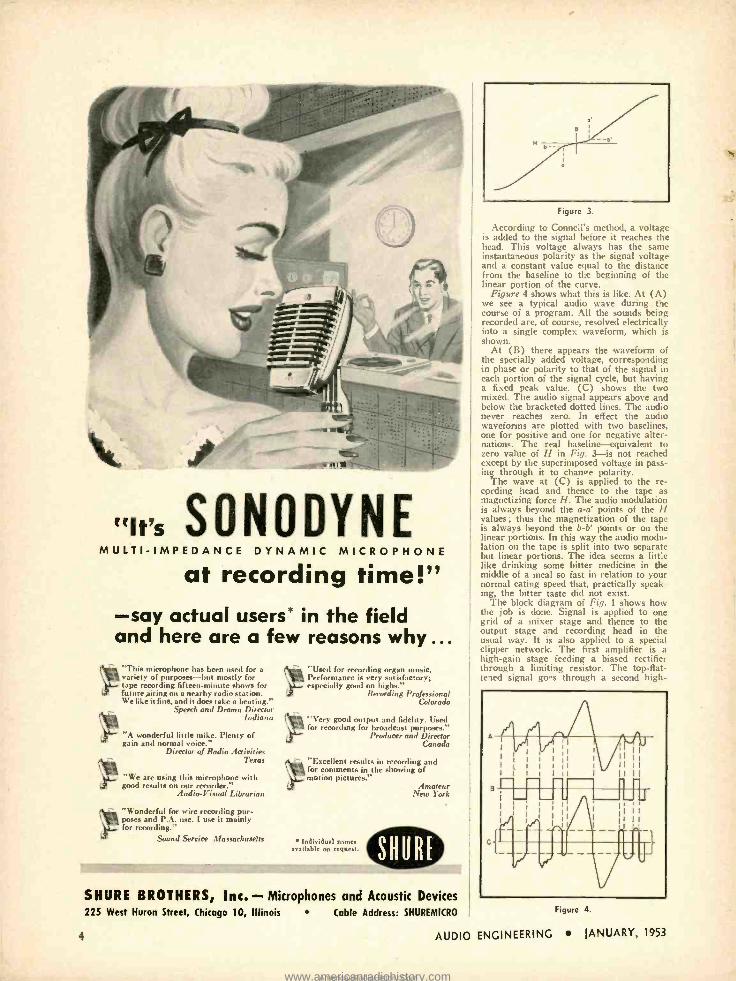
«W= SONODYNE MULTI -IMPEDANCE DYNAMIC MICRO PHONE
at recording time!" -say actual users' in the field and here are a few reasons why ...
This microphone has been used for a 1 variety of purposes -but mostly for
tape recording fifteen -minute shoes for future airing on a nearby radio station. We like it fine, and it does take a heating."
Speech and Drama Director Indiana
"A wonderful little mike. Plenty of gain and normal voice."
Director of Radio Activities Texas
"We are using this microphone with good results on our recorder."
Audio - Visual Librarian
" "Wonderful for wire recording pur - vi poses and P.A. use. I use it mainly for recording."
Sound Service Massachusetts
Used for recording organ music. Performance is very satisfactory; especially good on highs."
Recording Professional Colorado
"Very good output and fidelity. Used for recording for broadcast purposes."
Producer and Director Canada
"Excellent results in recording and for comments in the showing of motion pictures."
Individual names available on request.
Amateur New lorl:
SHURE BROTHERS, Inc. - Microphones and Acoustic Devices 225 West Huron Street, Chicago 10, Illinois
4
Cable Address: SHUREMICRO
Figure 3.
According to Connell's method, a n,itagc is added to the signal before it reaches the head. This voltage always has the same instantaneous polarity as the signal voltage and a constant value equal to the distance from the baseline to the beginning of the linear portion of the curve.
Figure 4 shows what this is like. At (A) we see a typical audio wave during the course of a program. All the sounds being recorded are, of course, resolved electrically into a single complex waveform, which is shown.
At (B) there appears the waveform of the specially added voltage, corresponding in phase or polarity to that of the signal in each portion of the signal cycle, but having a fixed peak value. (C) shows the two mixed. The audio signal appears above and below the bracketed dotted lines. The audio never reaches zero. In effect the audio waveforms are plotted with two baselines, one for positive and one for negative alter- nations. The real baseline-equivalent to zero value of H in Fig. 3-is not reached except by the superimposed voltage in pass- ing through it to change polarity.
The wave at (C) is applied to the re- cording head and thence to the tape as magnetizing force H. The audio modulation is always beyond the a -a' points of the H values ; thus the magnetization of the tape is always beyond the b -b' points or on the linear portions. In this way the audio modu- lation on the tape is split into two separate but linear portions. The idea seems a little like drinking some bitter medicine in the middle of a meal so fast in relation to your normal eating speed that, practically speak ing, the bitter taste did not exist.
The block diagram of Fig. 1 shows how the job is done. Signal is applied to one grid of a mixer stage and thence to the output stage and recording head in the usual way. It is also applied to a special clipper network. The first amplifier is a high -gain stage feeding a biased rectifier hrough a limiting resistor. The top -flat-
tened signal go "s through a second high-
, ,r,rl ; 1
1
I I I I I I I I I I
1 1 I I i II I I I I I
1 I I i I il I 11 I I
Bi
i - 1
I i I
I - i' -- ; p -p 1-- ir g I
Ftgurc 1.
AUDIO ENGINEERING JANUARY, 1953
www.americanradiohistory.comAmericanRadioHistory.Com
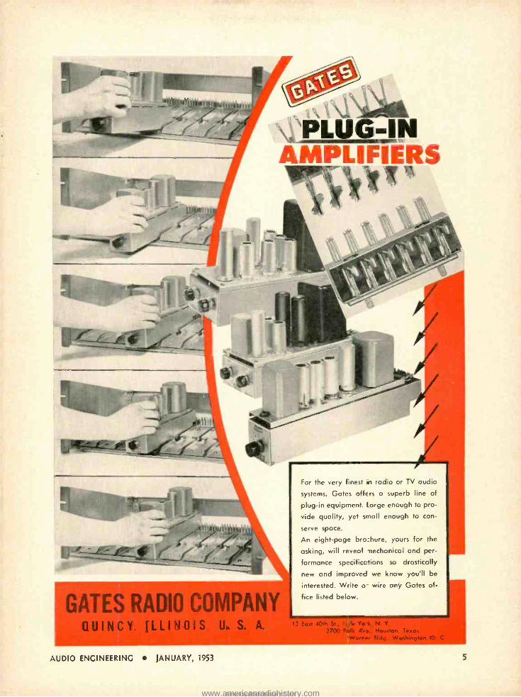
vPL11s -1N AMPLIFIÉRS
'V*"
4 -.- =--_
GATES RADIO COM QUINCY ILLINOIS U. S. A.
AUDIO ENGINEERING JANUARY, 1953
For the very finest in radio or TV audio
systems, Gates offers a superb line of
plug -in equipment. Large enough to pro-
vide quality, yet small enough to con-
serve space.
An eight -page bro :hure, yours for the
asking, will reveal -nechanical and per-
formance specifications so drastically
new and improved we know you'll be
interested. Write o- wire any Gates of-
fice listed below.
2700 Polk Ave., Houston. Tex Worn., Bldg . Wa
5
www.americanradiohistory.comAmericanRadioHistory.Com
ELECTRICAL
ENGINEER
PHYSICIST
with experience in
RADAR
r
ELECTRON ICS
Hughes Research and Develop- ment Laboratories, one of the nation's leading electronics organizations, are now creating a number of new openings in an important phase of their operations.
Here is what one of these positions gifers you:
THE COMPANY Hughes Research and De- velopment Laboratories, located in Southern Califor- nia, are presently engaged in the development and production of advanced radar systems, electronic computers and guided missiles.
THE NEW OPENINGS The positions are for men who will serve as technical advisors to government agencies and companies purchasing Hughes equip- ment- also as technical con- sultants with engineers of other companies working on associated equipment. Your specific job would be essentially to help insure successful operation of Hughes equipment in the field.
HUGHES
THE TRAINING On joining our organiza- tion, you will work in the Laboratories for several months to become thor- oughly familiar with the equipment which you will later help users to under- stand and properly employ. If you have already had radar or electronics experi- ence, you will find this knowledge helpful in your new work.
WHERE YOU WORK After your period of train - ing-at full pay -you may (1) remain with the Labor- atories in Southern Califor- nia in an instructive or administrative capacity. (2) become the Hughes repre- sentative at a company where our equipment is be- ing installed, or (3) be the
Hughes representative at a military base in this coun- try or overseas (single men only). Compensation is made for traveling and moving household effects, and married men keep their families with them at all times.
YOUR FUTURE In one of these positions you will gain all- around ex- perience that will increase your value to our organizes. tion as it further expands in the field of electronics. The next few years are certain to see large -scale commercial employment of electronic systems. Your training in and familiarity with the most advanced electronic techniques now will qualify you for even more impor- tant future positions.
How to apply:
RESEARCH AND DEVELOPMENT LABORATORIES
Engineering Personnel Department Culver City, Los Angeles County, California
ss
If you are under thirty-five years of age, and if you have an E.E. or Physics degree, write to the Laboratories, giving resumé of your experience.
Assurance is required that relocation of the applicant will not cause disruption of an urgent military project.
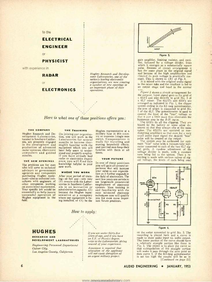
Figure 5.
gain amplifier, limiting resistor, and recti- fier, followed by a voltage divider, from which it emerges as a substantially square pulse. Because of circuit arrangement it has the same phase as the original signal and because of the high amplification and clipping its peak voltage is practically con- stant. This is shown in (B) of Fig. 4.
It is mixed with the original audio signal in the mixer tube and the resultant is fed to an output stage and head in the normal n-ay.
Figure 2 shows a circuit arrangement for the purpose. Input signal goes to the grid of a 6SF5 and also directly to grid No. 3 of a 6L7 mixer. The 6SF5's and 6H6's are arranged as indicated in Fig. 1, the clipper system ending in the 0.5 meg potentiometer, the arm of which is connected to grid No. 1 of the 6L7. The potentiometer is used to control the level of the "bias" voltage so that it just a little more than eliminates the hysteresis step in the B -H curve.
The 6H6's do all the clipping. They are biased by the battery or some other d.c. source so that they always clip at the same value. The 6SF5's are operated as non- distorting amplifiers so that even for a very small audio input signal the desired "bias" pulse will be created at the output.
The system may be calibrated for opti- mum "bias" value with a vacuum -tube volt- meter connected to each of the two 6L7 sig- nal grids. A random adjustment of the voltage divider is made, with a constant tone being fed to the system. Then a re- cording is made with various values of sig- nal voltage, the levels of each being read
Figure 6.
on the meter connected to grid No. 3. The recording is played back and a curve is made to show audio input vs. audio output. The lower portion of the curve should have a relatively straight portion like those in Fig. 5. The object is to place the curve so that extrapolation of the straight portion will make it pass through the zero point as does curve 1. If the 0.5 -meg potentiometer is set too high the results will be as in
[Continued on page 51]
6 AUDIO ENGINEERING JANUARY, 1953
www.americanradiohistory.comAmericanRadioHistory.Com
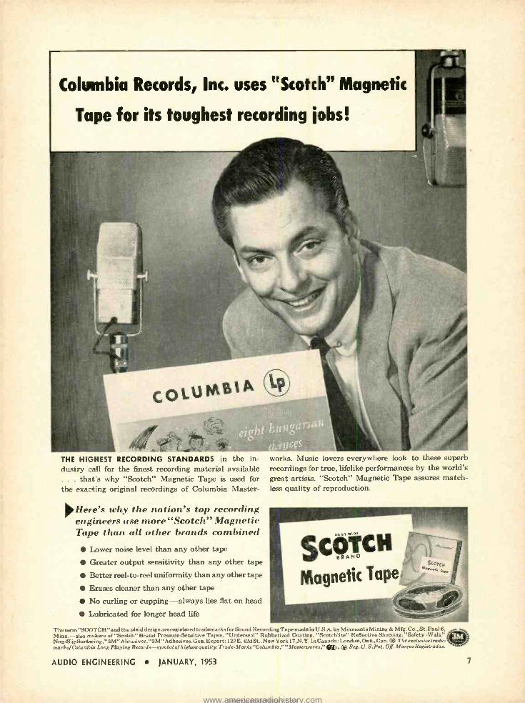
Columbia Records, Inc. uses "Scotch" Magnetic
Tape for its toughest recording jobs!
THE HIGHEST RECORDING STANDARDS in the in- dustry _all for the finest recording material available ... that s why "Scotch" Magnetic Tape is used for the exacting original recordings of Columbia Master-
Here's why the nation's top recording engineers use more "Scotch" Magnetic Tape than all other brands combined
Lower noise level than any other tape
Greater output sensitivity than any other tape
Better reel -to -reel uniformity than any other tape
Erases cleaner than any other tape
No curling or cupping- always lies flat on head
Lubricated for longer head life
works. Music lovers everywhere look to these superb recordings for true, lifelike performances by the world's great artists. "Scotch" Magnetic Tape assures match- less quality of reproduction.
4 at
SCO MIOn
CH
Magnetic Tape
The term "SCOTCH "and the plaid design are registered trademarks for Sound Recording Tape mede in U.S.A. by Minnesota Mining & Mfg. Co., St. Paul 6, Minn. -also makers of "Scotch" Brand Pressure- Sensitive Tapes, "Underseal" Rubberized Coating, "`.k.otchlite" Reflective Sheeting. Safety -Walk" Non-Slip Surfacing, "3M "Abrasives, "3M "Adhesives. Gen. Export: 122E. 42d St., New York 17,N. Y. In Canada: London, Ont., Can. (9 The exclusive trade- mark o/Columbia Long Playing Records -symbol of highest quality. Trade- Marks "Columbia, "Masterworks.' . Reg. U.S. Pat. Off. MarcasRegistradas.
AUDIO ENGINEERING JANUARY, 1953 7
www.americanradiohistory.comAmericanRadioHistory.Com
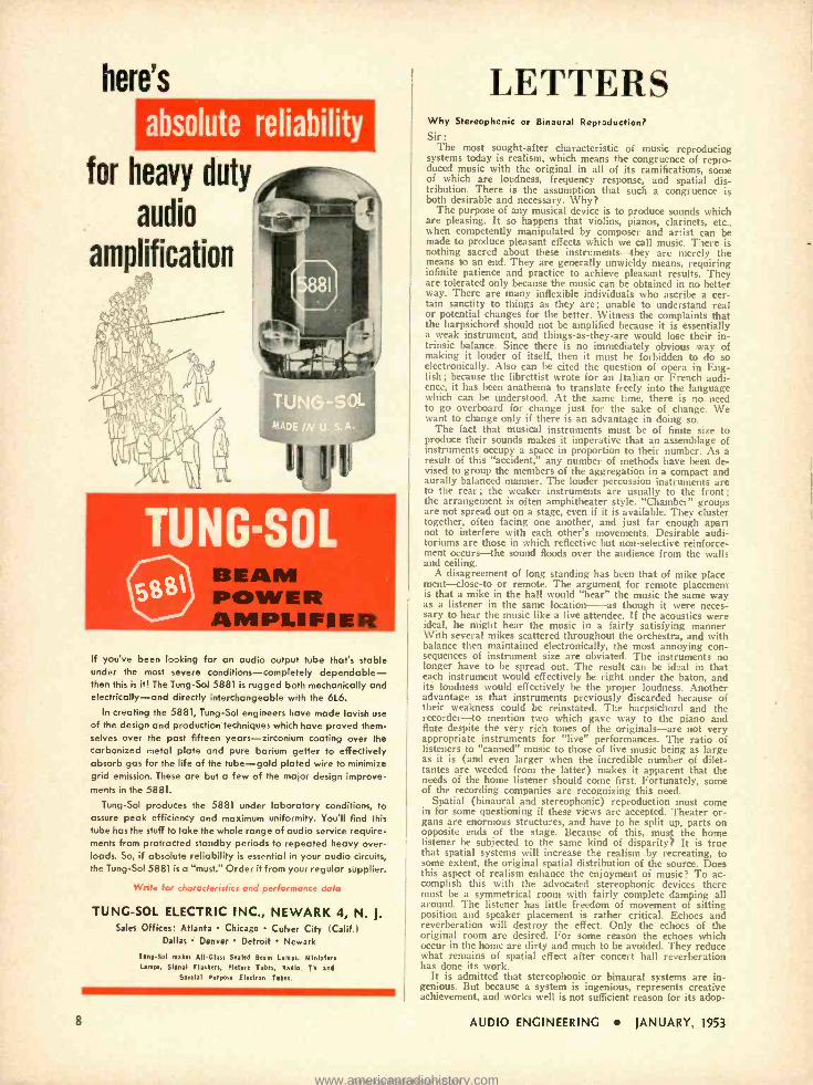
here's
absolute reliability
for heavy duty
audio
amplification
BEAM POWER AMPLIFIE
If you've been looking for an audio output tube that's stable under the most severe conditions -completely dependable - then this is it! The Tung -Sol 5881 is rugged both mechanical'y and electrically -and directly interchangeable with the 6L6.
In creating the 5881, Tung -Sol engineers have made lavish use of the design and production techniques which have proved them- selves over the past fifteen years - zirconium coating over the carbonized metal plate and pure barium getter to effectively absorb gas for the life of the tube -gold plated wire to minimize grid emission. These are but a few of the major design improve- ments in the 5881.
Tung -Sol produces the 5881 under laboratory conditions, to assure peak efficiency and maximum uniformity. You'll fit-el this tube has the stuff to take the whole range of audio service require- ments from protracted standby periods to repeated heavy over- loads. So, if absolute reliability is essential in your audio circuits, the Tung -Sol 5881 is a "must." Order it from your regular supplier.
Write for characteristics and performance data
TUNG -SOL ELECTRIC INC., NEWARK 4, N. J.
Sales Offices: Atlanta Chicago Culver City (Calif.) Dallas Denver Detroit Newark
T ono ,Sol makes All,G lass Sealed Beam lamps, Al Inlet ere
Lamps, Signal Flashers, Picture T ubes, Radio TV and
Special Purpose Electron T uses.
LETTERS Why Stercoph_nic or Binaural Rcpraduction?
Sir :
The most sought -after characteristic of music reproducing systems today is realism, which means the congruence of repro- duced music with the original in all of its ramifications, some of which are loudness, frequency response, and spatial dis- tribution. There is the assumption that such a congruence is both desirable and necessary. Why?
The purpose of any musical device is to produce sounds which are pleasing. It so happens that violins, pianos, clarinets, etc., when competently manipulated by composer and artist can be made to produce pleasant effects which we call music. There is nothing sacred about these instruments -they are merely the means to an end. They are generally unwieldy means, requiring infinite patience and practice to achieve pleasant results. They are tolerated only because the music can be obtained in no better way. There are many inflexible individuals who ascribe a cer- tain sanctity to things as they are; unable to understand real or potential changes for the better. Witness the complaints that the harpsichord should not be amplified because it is essentially a weak instrument, and things -as- they -are would lose their in- trinsic balance. Since there is no immediately obvious way of making it louder of itself, then it must be forbidden to do so electronically. Also can be cited the question of opera in Eng- lish ; because the librettist wrote for an Italian or French audi- ence, it has been anathema to translate freely into the language which can be understood. At the same time, there is no need to go overboard for change just for the sake of change. We want to change only if there is an advantage in doing so.
The fact that musical instruments must be of finite size to produce their sounds makes it imperative that an assemblage of instruments occupy a space in proportion to their number. As a result of this "accident,' any number of methods have been de- vised to group the members of the aggregation in a compact and aurally balanced manner. The louder percussion instruments are to the rear ; the weaker instruments are usually to the front; the arrangement is often amphitheater style. "Chamber" groups are not spread out on a stage, even if it is available. They cluster together, often facing one another, and just far enough apart not to interfere with each other's movements. Desirable audi- toriums are those in which reflective but non -selective reinforce- ment occurs -the sound floods over the audience from the walls and ceiling.
A disagreement of long standing has been that of mike place meat- close -to or remote. The argument for remote placement is that a mike in the hall would "hear" the music the same way as a listener in the same location -as though it were neces- sary to hear the music like a live attendee. If the acoustics were ideal, he might hear the music in a fairly satisfying manner With several mikes scattered throughout the orchestra, and with balance then maintained electronically, the most annoying con- sequences of instrument size are obviated. The instruments no longer have to be spread out. The result can be id °al in that each instrument would effectively be right under the baton, and its loudness would effectively be the proper loudness. Another advantage is that instruments previously discarded because of their weakness could be reinstated. The harpsichord and the recorder -to mention two which gave way to the piano and flute despite the very rich tones of the originals -are not very appropriate instruments for "live" performances. The ratio of listeners to "canned" music to those of live music being as large as it is (and even larger when the incredible number of dilet- tantes are weeded from the latter) makes it apparent that the needs of the home listener should come first. Fortunately, some of the recording companies are recognizing this need.
Spatial (binaural and stereophonic) reproduction must come in for some questioning if these views are accepted. Theater or- gans are enormous structures, and have to be split up, parts on opposite ends of the stage. Because of this, must the home listener be subjected to the same kind of disparity? It is true that spatial systems will increase the realism by recreating, to some extent, the original spatial distribution of the source. Does this aspect of realism enhance the enjoyment of music? To ac- complish this with the advocated stereophonic devices there must be a symmetrical room with fairly complete damping all around. The listener has little freedom of movement of sitting position and speaker placement is rather critical. Echoes and reverberation will destroy the effect. Only the echoes of the original room are desired. For some reason the echoes which occur in the home are dirty and much to be avoided. They reduce what remains of spatial effect after concert hall reverberation has done its work.
It is admitted that stereophonic or binaural systems are in- genious. But because a system is ingenious, represents creative achievement, and works well is not sufficient reason for its adop-
8 AUDIO ENGINEERING JANUARY, 1953
www.americanradiohistory.comAmericanRadioHistory.Com
04,0titvu
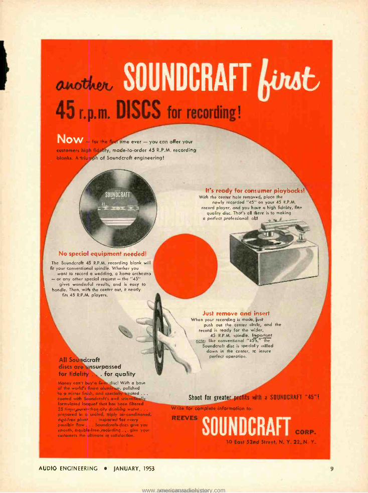
45 r.p.m. DISC for recording!
time ever - you can offer your
y, made -to -order 45 R.P.M. recording
of Soundcraft engineering!
It's ready for consumer playbacks! With the center hole remaved, place the
newly recorded "45" on your 45 R.P.M.
record player, and you have a high fidelity, fine quality disc. That's al there is to making
a perfect professional oh!
No special equipment needed! The 5oundcraft 45 R.P.M. recording blank will
fit your conventional spindle. Whether you want to record a wedding, a home orchestra - or any other special request - the "45" gives wonderful results, and is easy to
handle. Then, wit, the center out, it neatly fits 45 R.P.M. players.
tl . dcraft discs nsurpassed for fidelity . , . for quality Money can't buy a fi disc! With a base of the world's finest of , polished to a mirror fin sh, and sp ated .. .
coated with Soundcrafts o ly formulated lacquer that has been filtered 25 times purer than city drinking water .. .
prepared in o sealed. triply air -conditioned, dust -free plant ... inspected for every possible flaw ... Soundcroft discs give you smooth, trouble -free recording ...give your customers the ultimate in satisfaction.
Just remove anc insert When your recording is made, just
push out the center :irc le, and the record is ready for the wiser,
45 R.P.M. spindle. Impo-tont pote: like conventional "45's," the N.
Soundcraft disc is special y milled down in the center, tc insure
perfect operation.
Shoot for greater plats Write for
UNDCRAFT "45"!
SOUNDCRAFT ORP.
, N. Y.
AUDIO ENGINEERING JANUARY, 1953
www.americanradiohistory.comAmericanRadioHistory.Com
NAN
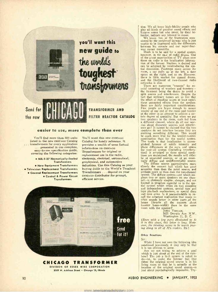
Send for
the new
you'll want this
new guide to
SAW WVrVWW
toughest- tots
TRANSFORMER AND
FILTER REACTOR CATALOG
easier to use, more complete than ever
You'll find more than 500 units listed in the new CHICAGO Catalog
... transformers for every application ... presented in one complete, easy -to -use specification guide,
covering the following categories:
MIL -T -27 Hermetically- Sealed Transformers
New Equipment Transformers Television Replacement Transformers
General Replacement Transformers Control & Power Circuit
Transformers
You'll want this new CHICAGO Catalog for handy reference. It provides a wealth of terse factual information on CHICAGO
Transformers for original or replacement use in the radio, electronic, electrical, aeronautical, geophysical, and automotive industries. Use this Catalog as your buying guide to the World's Toughest Transformers ... depend on your CHICAGO distributor for prompt, efficient service.
UGtq.... .. _...
free Send
for it!
CHICAGO TRANSFORMER DIVISION OF ESSEX WIRE CORPORATION
3501 W. Addison Slree Chicago 18, Illinois
10
tion. We all know high -fidelity people who play all kinds of peculiar sound effects and bizarre music but who never, by their be- havior, indicate any interest in music.
We know, too, of the frustration occa- sioned by the perplexed layman who is just unable to be impressed with the differences between his console and our super -four- way corner monoliths.
Much is to be said for a spatial system, however, in the case of radio drama. One of the great superiorities of TV plays over those on radio is the localization informa- tion of the former. Realism is desired and can be achieved by reintroducing the spa- tial dimension. Footsteps move across the room, a car pulls up at the left, a door opens on the right, and so on. However. there is little market for canned drama. and the likelihood of two -channel radio networks is slim.
There are numerous "reasons" for co- axial mounting of woofers and tweeters - the foremost being the desire to avoid a split source and interference. Despite the fact that ordinary homes are so live that the effect of standing waves at least equals these unwanted effects from the speaker. these are fairly important considerations. Few people are brave enough to mount woofer at one end of the room and tweeter at the other in an attempt to achieve a cer- tain degree of spatiality. But when we put two speakers in the room, each fed from a different channel, where do all our wor- ries about disparate sources and interfer- ence go? It cannot be claimed that the two speakers do not interfere because they are emitting something different. This would he much more true for the woofer- tweeter combination than for the spatial system. The truth is that localization is accom- plished because of subtle intensity and phase differences at the ears, and unless the over -all system (including reverbera- tion) is arranged so these special condi- tions are maintained, the results will either be of separated sources. or of an essen- tially diffuse and undifferentiable source.
The diffuse source approximates more closely the concert hall which has good acoustics than does the point source, and perhaps more so than does the two -channel system. The diffuse system-one which em- ploys two or more speakers on one chan- nel-is obviously simpler, cheaper, and not limited in program material as is the spa- tial system which relies on two complete and independent systems, special tape and tape playback mechanisms, or special discs and tone arms. Is it uncomfortable to re- call the reluctant realization that music so often sounds better in other parts of the house (despite all the concern about tweeter beam -width) than in the same room with the speaker?
JOHN VERSAGE, 5621 Georgia Ave. N.W., Washington 11, D. C.
(Even with a few parts eliminated to fit it in this space, this letter is long. How- ever, the thinking seems to be worth pass- ing along to all of "'Ps readers. En.)
Other Reactions
Sir: While I have not seen the following idea
mentioned previously, it may only be that it is too obvious to some.
Are we not trying to achieve a goal which is just about at the end of the rain- bow? The job a hi -fi system is asked to do -i.e., to make the listener feel that either the original sound source is in his living room or that he is actually at the location of the original sound source -is just about psychologically impossible. Try-
AUDIO ENGINEERING JANUARY, 1953
www.americanradiohistory.comAmericanRadioHistory.Com
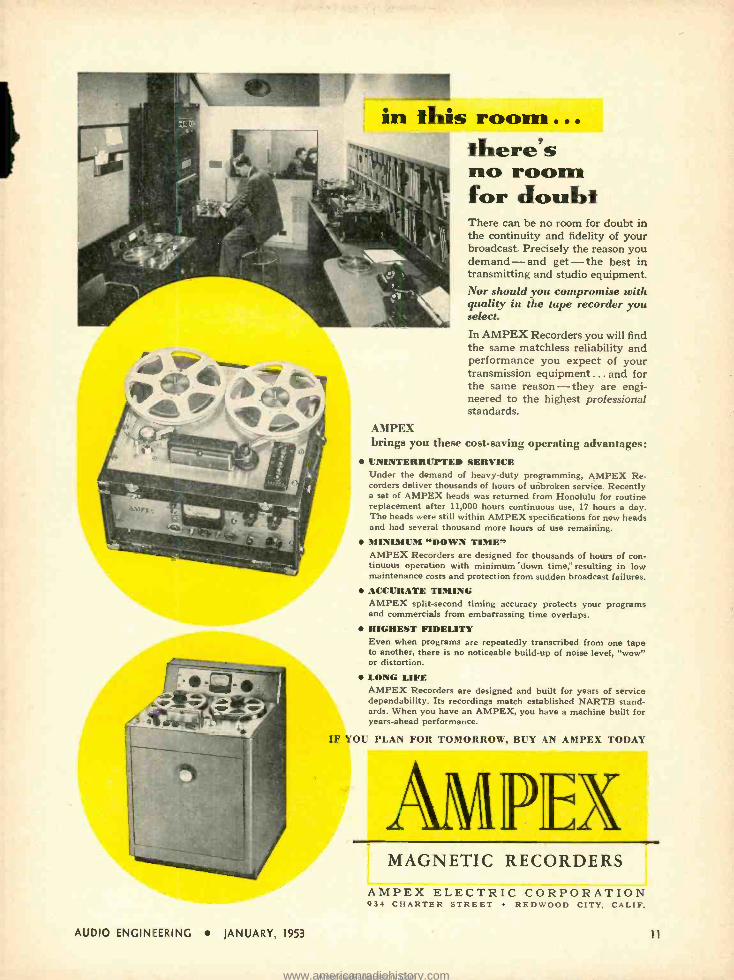
in this room... there's no room for doubt There can be no room for doubt in the continuity and fidelity of your broadcast. Precisely the reason you demand -and get -the best in transmitting and studio equipment. Nor should you compromise with quality in the tape recorder you select.
In AMPEX Recorders you will find the same matchless reliability and performance you expect of your transmission equipment ... and for the same reason - they are engi- neered to the highest professional standards.
AMPEX brings you these cost - saving operating advantages: UNINTERRUPTED SERVICE Under the demand of heavy -duty programming, AMPEX Re- corders deliver thousands of hours of unbroken service. Recently a set of AMPEX heads was returned from Honolulu for routine replacement after 11,000 hours continuous use, 17 hours a day. The heads were still within AMPEX specifications for new heads and had several thousand more hours of use remaining. MINIMUM "DOWN TIME' AMPEX Recorders are designed for thousands of hours of con- tinuous operation with minimum "down time," resulting in low maintenance costs and protection from sudden broadcast failures. ACCURATE TIMING AMPEX split- second timing accuracy protects your programs and commercials from embarrassing time overlaps. HIGHEST FIDELITY Even when programs are repeatedly transcribed from one tape to another, there is no noticeable build -up of noise level, "wow" or distortion.
LONG LIFE AMPEX Recorders are designed and built for years of service dependability. Its recordings match established NARTB stand- ards. When you have an AMPEX, you have a machine built for years -ahead performance.
IF YOU PLAN FOR TOMORROW, BUY AN AMPEX TODAY
AMPEX MAGNETIC RECORDERS
AMPEX ELECTRIC CORPORATION 934 CHARTER STREET REDWOOD CITY, CALIF.
AUDIO ENGINEERING JANUARY, 1953 11
www.americanradiohistory.comAmericanRadioHistory.Com
YOUR POSITIVE
F. Perfect Precision
Prints MECHANICAL MEMORY ...
AUTOMATIC CONTROL . , . NO NOTCHING
Each individual film has its own Printing Control Strip, which de- termines printing exposures, filter changes (for color) and effects,and stores up this knowledge for trans- f er to the printing machine itself. This Control Strip permits exact duplication at any time.
12
YOUR ASSURANCE OF BETTER 16mm PRINTS
15 Years Research and Spe- cialization in every phase of 16mm processing, visual and aural. So organized and equip- ped that all Precision jobs are of the highest quality.
Individual Attention is given each film, each reel, each scene, each frame - through every phase of the complex business of processing - assuring you of the very best results.
Our Advanced Methods and our constant checking and adop- tion of up -to- the. minute tech- niques, plus new engineering principles and special machinery
Precision Film Laboratories -a di- vision of J. A. Maurer, Inc., has 14
years of specialization in the 16mm field, consistently meets the latest de- mands for higher quality and speed.
enable us to offer service un- equalled anywhere!
Newest Facilities in the 16mm field are available to customers of Precision, including the most modern applications of elec- tronics, chemistry, physics, optics, sensitometry and densitometry- including exclusive Maurer - designed equipment -your guar- antee that only the best is yours at Precision!
P1W OISION FILM LABORATORIES, INC.
21 West 46th St.,
New York 19, N.Y.
JU 2 -3970
ing to make a listener believe something he knows is not so is difficult, whereas if he believes that what he is going to hear is real, a very poor reproducing system is all that is necessary to uphold the illusion. For example, vocalists with the best dance orchestras nearly always use relatively poor p.a. systems, yet it never dawns on a high percentage of the listeners at the dance that they do not hear the real live vocalist at all. The original source is nearly always completely masked by the reproducing system. I am convinced that if an audience were assembled in an audito- rium in which high -fidelity speakers were placed along the front of the stage and an orchestra placed behind an opaque but acoustically transparent screen to produce the music unknown to the audience, a high percentage of this audience would report that the high -fidelity system is good but still does not quite sound real.
I do not mean to imply that we should stop trying to improve high -fi systems, but merely make the suggestion that perhaps we should re- evaluate the state of the art in this light. Maybe some who are becom- ing neurotic trying to make their systems sound real will be somewhat consoled. Most of the present -day systems sound fairly good to me, but no matter how good they sound, I cannot sit in my living room, close my eyes and be transferred by magic carpet to the symphony auditorium, nor does the magic carpet take me back to my living room when I see a vocalist but hear only a relatively inferior public address system.
THOMAS O. DIXON Head, Instrumentation Division Sound Division, Code 4006 Naval Research Laboratory Washington 25, D. C.
ORFEO'S NEW MUSIC STUDIO
High -fidelity grown up -might well be the name for the new sound studios opened on November 19th at 19 E. 48th St., New York, for it has introduced a new method of merchandising audio to the customer. Under the direction of Ben Pinz, Orfeo has built two demonstration rooms which
are devoid of bare equipment, and which duplicate typical home environments-one modern and the other in traditional decor.
Planned for the Aunt Minnie type of buyer, Orfeo offers a normal living -room arrangement with several "package" sys -' tems suitably cabineted, and working as complete units so the non -technical listoncr may judge performance and can see for himself just how high -quality sound repro- duction would fit into his own home. Or- feti s services include complete decoration and acoustical treatment when required, bringing the knowledge of the custom builder and the talents of the decorator together in a unique and workable combi- nation.
AUDIO ENGINEERING JANUARY, 1953
www.americanradiohistory.comAmericanRadioHistory.Com
%-)6-10'frir
APPIleA00/115
-
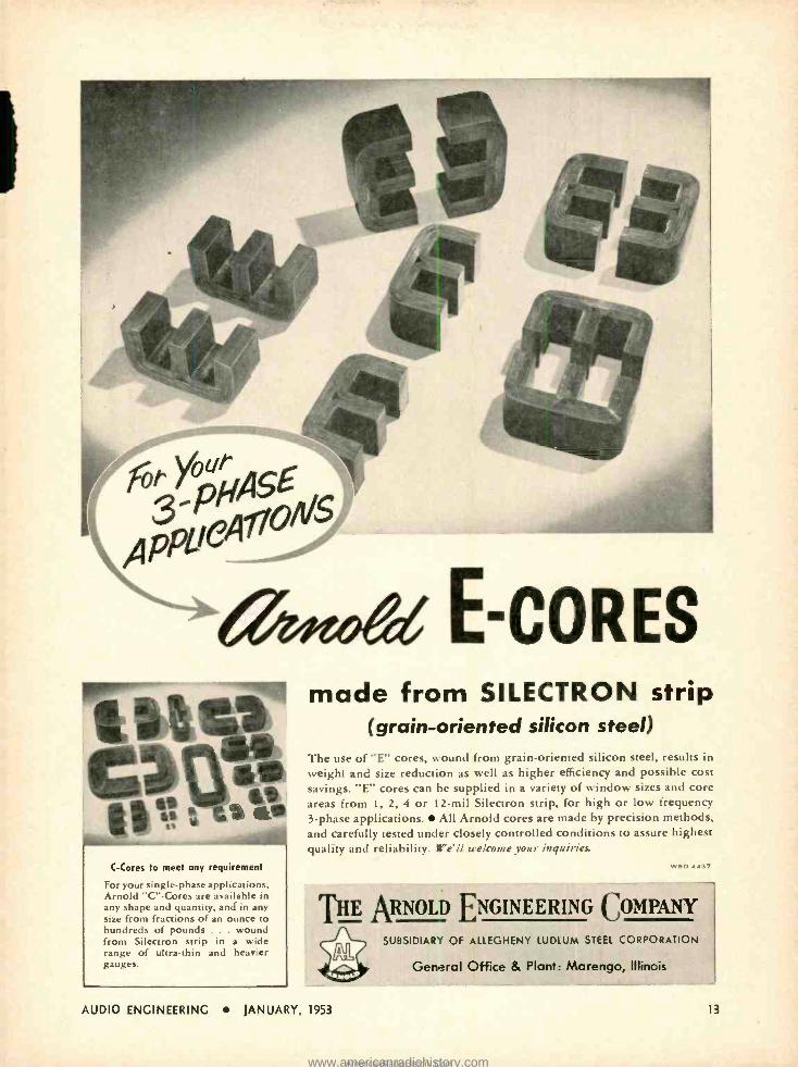
7/Pedd E-CORES
C144V, C -Cores to meet any requirement
For your single -phase applications, Arnold "C" -Cores are available in any shape and quantity, and in any size from fractions of an ounce to hundreds of pounds . wound from Silectron strip in a wide range of ultra -thin and heavier gauges.
made from SILECTRON strip (grain -oriented silicon steel)
The use of "L" cores, wound from grain -oriented silicon steel, results in weight and size reduction as well as higher efficiency and possible cost savings. "E" cores can be supplied in a variety of window sizes and core areas from 1, 2, 4 or 12 -mil Silectron strip, for high or low frequency 3 -phase applications. All Arnold cores are made by precision methods, and carefully tested under closely controlled conditions to assure highest quality and reliability. We'll welcome your inquiries.
THE ARNOLD ENGINEERING COMPANY
SUBSIDIAR" OF ALLEGHENY LUDLUM STEEL CORPORATION
AUDIO ENGINEERING JANUARY, 1953
General Office & Plant: Marengo, Illinois
13
www.americanradiohistory.comAmericanRadioHistory.Com
your hi- fidelity
problems with
CONE SPEAKERS
HILÓWE QUALITY!
COST! L
____HIGHEST
MODEL 6201 - COAXIAL SPEAKER SYSTEM. Now gen. orally acknowledged to be industry's finest value in o high quality 12" speaker, TRUE coaxial dual range system comprising clean sounding woofer with heavy exclusive Alnico 5W magnet,
DRIVER TYPE tweeter with y- "Reciprocating flares' wide
ongle horn, and BUILTIN crossover network complete with "Balance" control.
DIFFUSICONE-12 - WIDE RANGE WIDE ANGLE 12" SPEAKER. Exclusive "diffusi- cone" design utilizes the bene- fits of dual -horn loading, radial projection and diffraction prin- ciples to achieve unsurpassed quality and sound distribution from a single unit speaker. Enjoy full fidelity ANYWHERE In the room . . at o surpris. Ingly reasonable cost.
waszcinemeweussannil
DIFFUSICONE -8 - WIDE ANGLE 8" SPEAKER. Same os the DIf fuscione-12 except In 8" OIL Remarkable fidelity and ex seplionol sensitivity andpower handling capacity make this a truly outstanding eight. Ideal for use where space is Iimlfed, and is also a perfect selection for o mid -range speaker in 3 -way systems.
MODEL 6200 -EXTENDED RANGE 12" SPEAKER. Designed for gen- eral applications, capable of high- ly efficient FULL-BODIED response throughout the operating spec- trum. May be used with equal facility to improve c mmerciol radio, TV, phono sets, high quality sound re- inforcement in night clubs, churches, schools, etc., or woofer. The 6200 mutt be heard to be appreciated.
MODEL C -15W -DUAL IMPEDANCE RANGE 15" WOOFER. Brand new low frequency reproducer embodying many exclusive ad trance features. Its superior re spent* and acoustic output Is due, in port, to a newly University- developed cone and voice coil suspension system permitting the greatest axial movement ever achieved. The incredibly low distortion results from a new magnet assembly.
There is a UNIVERSITY Tweeter for every application and pocketbook. Write for d-- 'prive
illustrated literature. Address Desk A -1
LOUDSPEAKERS /INC 80 SO. KENSICO AVE., WHITE PLAINS, N. Y.
l4
Binaural Radio Broadcasting HAROLD T. SHERMAN
History and prospects of a new step in the search for optimum realism in sound reproduction.
AS TIME MARCHES ON, new development: in audio play an important part in relaying by radio greater realism
through a feeling of presence. One of the earliest attempts to transmit this feeling of presence was by means of a dual telephone circuit, using one circuit for each ear, be- tween the Paris Opera House and the Paris Electrical Exhibition in 1881- Binaural broadcasting has demonstrated that the list- ening audience outside the studio can enjoy the program with less listening effort and less aural fatigue.
A brief history on the subject of binaural broadcasting reveals that the interest of engineers and experimenters was sparked off in the very early 1920's when radio broadcasting was just beginning. At that time the limitations of the audio components used for converting speech and music in the studio into realistic sound in the home created the need for radical changes in sound reproduction methods. In those days the parlor stereoscope with pictures pro- duced by a stereo (binocular) camera were well known for their ability to give us third -dimensional visual reproduction.
Radio fans around New Haven, Con- necticut, were probably the first to hear the results of binaural broadcasting. F. M. Doolittle, Professor of Electrical Engineer- ing at Yale University, pioneered this radio system and applied for U. S. patents in 1921. He had articles published in Electrical World, and in the radio section of the New York Herald Tribune in 1925, giving gen- eral information on his findings, with a description and photographs of Station WPAT. which operated binaurally during 1925. WPAJ used two 50 -watt AM trans- mitters, one on 1320 kc and the other on 1110 kc. One antenna was excited by both transmitters whose antenna coils were con- nected in parallel.
During this same period, KDKA in Pittsburgh also used Mr. Doolittle's system experimentally and eventually bought his patents. Unfortunately the crowding of the AM band of frequencies made it impracti- cal to continue, or expand, binaural radio at that early period.
In the early 1930's, Bell Telephone Laboratories gave several technical demon- strations of their research on stereophonic sound reproduction for motion pictures. These demonstrations, given to the AIEE, the Acoustical Society of America, and other engineering groups, made a deep impression of the listening advantages, but a practicable two -channel, non -interfering, radio-audio circuit was not readily avail - able.
Present Interest Crowing
Revival of development of binaural sound reproduction came when Magnecord, Inc. of Chicago, produced a special twin -track magnetic tape recorder for the Navy De- partment. It was demonstrated in 1951 that this unit basically was suited to record and reproduce music and sound in third dimen- sion for special music study.
e
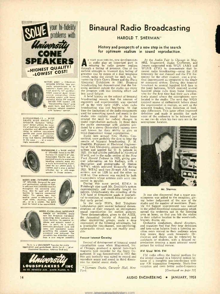
Sherman Studio, Carnegie Hall, New York.
AUDIO
At the Audio Fair in Chicago in May, 1952, Magnecord, Radio Craftsmen, and Jensen cooperated with WGN (AM) and WGNB (FM) to demonstrate that bi- naural radio broadcasting -using the AM frequency for one channel and the FM fre- quency for the other channel -was a prac- tical improvement as compared to the single or monaural system. During this binaural broadcast to several hundred hi -fi fans in the hotel ballroom, WGN received several hundred phone calls from home listeners, who for the first time had their ears effec- tively placed where the microphones were located in the studio. The next day WGN received scores of enthusiastic letters about the improvement in realism, as well as the apparent freedom from distortion of loud- ness differences. This latter effect improved definition and made it possible for each voice of the orchestra to be followed just as one can do when his two ears are in the microphone location.
Mr. Sherman
It was also discovered that a space con- sciousness was added to the reception, giv- ing better judgement of the size of the studio and the number of musicians. Possi- bly the biggest improvement was noticed in the added directional consciousness which spread the orchestra out in the listening area at home, so that you felt the violins in their relative location to the woodwinds. brasses, drums, etc.
Orchestra conductors, choral directors, and organists find that they hear definition and tone -value balance from a listening po- sition more normal to their audience when they review their work binaurally. Or- chestras and choirs can be rehearsed by assistants or students, with a delayed re- production creating a most accurate sound picture for critical review.
AM Used With FM
FM radio offers the logical medium for the second channel in a binaural system be- cause of a complete non -interference with any AM transmitter frequency. Static -free reception and even better audio -frequency
[Continued on page 71]
ENGINEERING JANUARY, 1953
www.americanradiohistory.comAmericanRadioHistory.Com
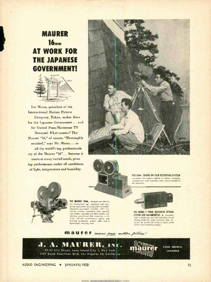
MAURER
16mm
AT WORK FOR
THE JAPANESE
GOVERNMENT! I
Ian Mutsu, president of the
International Motion Picture
Company, Tokyo, makes films
for the Japanese Government ... and
for United Press -Movietone TV
Newsreel. What camera? The
Maurer "16," of course. "Thoroughly
satisfied," says Mr. Mutsu ... as
all the world's top professionals
say of the Maurer "16" ... because it
meets so many varied needs, gives
top performance under all conditions
of light, temperature and humidity.
1. . 37-0
1107 So
ENE 111M. SIINI-/N-FIEI RECORDING SYSTEM combines the highest fidelity in 16mm recording practice with wide flexibility and extreme simplicity of operation.
TIE MANNER 11MM., designed specifically for professional use, equipped with pre-
sins highpower focusing and viewfinder. Standard equipment includes: 23S° dis- solving shutter, autonatie fade eontrol, view finder, sunshade sad filter holder, one 400 -foot geardriven film magazine, a 60 cycle 115-volt synchronous motor, one 8frame handerank, power cabk and a
lightweight carrying case.
THE MOTEL F PRIME RECORDING OPTICAL
SYSTEM AHI GALVANOMETER. A rtld,t lick: modulating to it for recording sound photographically upon standard film, re. quires no special servicing or spare parts (other than recording larcp).
m a u r e r
. MAURER, 1. 31st Street, Long Island City 1, New Yo
th Robertson Blvd., Los Angeles 35, Calif
AUDIO ENGINEERING JANUARY, 1953
Cw
krnia
Y(117n)1,t,.. maurer CABLE ACC RESS
JAMAUFER
15
www.americanradiohistory.comAmericanRadioHistory.Com
EDITOR'S REPORT NEW YEAR'S RESOLUTIONS
COMES THE FIRST of January and many of us have the urge to make resolutions. Like many a reader, we felt these urges, and even thought out the first
few paragraphs before putting them on paper. Since they seemed somewhat familiar, we checked back to January, 1952, to make sure we were not simply re- peating ourselves. Believe it or not, we found many of the same words and expressions, not to mention ideas. If 1E were like some magazines,. that would not have been disastrous, since few readers would have had the previous January's copy to compare. But we know that a large percentage of iE's readers keep complete files, and (assuming anybody reads this page at all) they would probably remind us of the repetition. We like to think that 1952's first Report was well written, and that it contained the credo we intend always to follow. But we must admit that we have not done everything we hoped to during the last year.
One of the changes we aimed for was to attempt to enlighten the novice in our field in the technical aspects of audio. We have made some progress in that direc- tion, but we have not done all we would have liked to. We have included much material that scarcely could be called "engineering" in an attempt to provide the max- imum coverage of the entire audio field. As a result, the more technical- minded of our readers were inclined to think that there was too much "butter on the pop- corn." Keeping a desirable balance between the techni- cal and the non -technical articles is like walking a tightrope. We try to please every one of our readers, and we realize that our future depends on how well we succeed.
On the credit side, we note that in 1952 we had a total of 762 pages -both editorial and advertising -as compared to 640 in 1951, an increase of 19 per cent. This corresponds quite closely to two extra issues, since the average was 63.5 pages. For this gain, we are in- debted to our advertisers, for only through their sup- port is it possible to produce a magazine. They are re- sponsible for the 96 and 92 page issues of October and November, and we are pleased that they have seen fit to use more of . 's pages to carry their messages to you.
And so it is, on the threshold of a new year, that we salute our advertisers. They work the year around to make their products as good as they know how, for they too have to please their customers. Without ad- vertisers we wouldn't exist -and many of our readers would not be so well informed about the products that make their spare time interesting -the products that bring the best of sound reproduction into the homes of discerning music lovers. No matter how the program arrives in our living rooms -by AM or FM radio, by wired music systems, by light waves, or over the water pipes even -it is the program that is important. In the final count, audio equipment must be involved from the moment the original sound is created in the studio or auditorium until it is recreated in our homes. Until someone comes along with a new method of sound reproduction, audio appears to offer the best possibility.
BINAURAL OR STEREOPHONIC? It isn't often that 2E devotes an entire issue to any
one subject, but if any single issue can rightly be called
16
a special one, this is it. From the reception it had at the recent Audio Fair in New York, it would appear that the newest thing in the audio field will involve two completely separate channels -which means twice as many amplifiers, twice as many speakers, twice as many signal sources. In the studió it will involve twice as many microphones in addition to amplifiers, attenu- ators, loudspeakers, and all the other elements in a transmission system.
Binaural broadcasting is certain to require new tech- niques -one of the most important being that of micro- phone placement, for with the present plans which in- volve both AM and FM radio channels, each program must sound well by itself, since many listeners will not be equipped to reproduce both at the same time. We have not got that far in our coverage of the binaural picture yet, but it is sure to come in the next year. In any case, it is sure to give us an opportunity of com- paring systems quite easily- something which many of us don't do with a single set of equipment. This swing toward binaural or stereophonic broadcasting should bring out many new developments in the next twelve months. For the present, however, we hope we have covered the field reasonably well, as evidenced by the articles on pages 14, 22, 25, and 46. We will keep in- formed on this subject, and will pass on all the informa- tion we receive.
SOUND REPRODUCTION COURSE
Edgar M. Villchur, who is currently authoring the series entitled "Handbook of Sound Reproduction" is beginning a new course on the subject of sound repro- duction at New York University, Division of General Education. This course begins on February 4 and runs until May 20, meeting at the Washington Square cen- ter on Wednesday evenings from 7:00 to 9:45 p.m. Further information can be obtained from NYU, and registration by mail or in person begins on January 19.
TAPE RECORDING IN ICELAND
We note with interest that the proceedings of the Iceland Parliament at Reykjavik are to be preserved for future generations by means of tape recording equip- ment recently installed in Iceland's two chambers of parliament. With eleven Stancil- Hoffman recording units, the entire proceedings of the General Assembly's continuous debate will be recorded. We hope this prac- tice will spread to the Western Hemisphere before many more months.
STANDARDIZATION FOR LOUDSPEAKERS
It has been suggested that loudspeakers be standard- ized as to polarity, and be marked so that two speakers can be connected in parallel without trying to cancel each other. The proposal from one of Æ's readers is that a polarizing symbol be applied to that terminal which, when fed with a positive voltage, will result in an outward cone movement. This seems simple enough, and would certainly help with horn -type tweeters, where it is nigh onto impossible to determine which way the diaphragm moves when we apply a small volt- age from a battery.
AUDIO ENGINEERING JANUARY, 1953
www.americanradiohistory.comAmericanRadioHistory.Com
4
Ç
/Jlf lCVielP//LCP
w
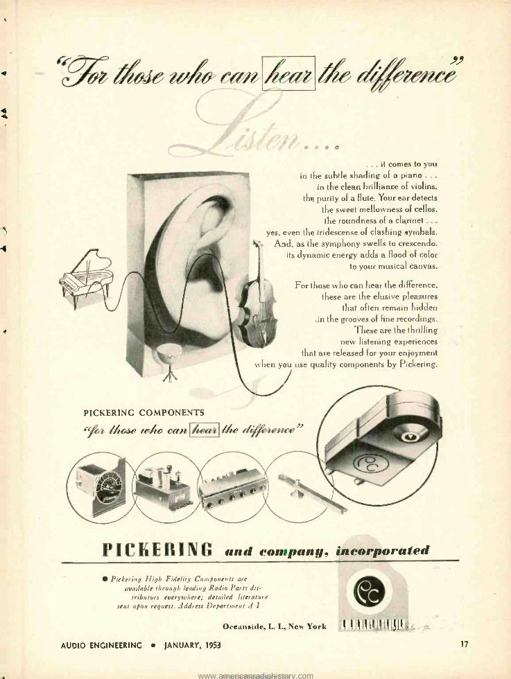
. it comes to you in the subtle shading of a piano . . .
in the clean brilliance of violins,
the purity of a flute. Your ear detects the sweet mellowness of cellos, the roundness of a clarinet ...
yes. even the iridescense of clashing symbals. Aid. as the symphony swells to crescendo.
its dynamic energy adds a flood of color to your musical canvas.
For those who can hear the difference. these are the elusive pleasures
that often remain hidden in the grooves of fine recordings.
These are the thrilling new listening experiences
that are released for your enjoyment when you use quality components by Pickering.
PICKERING COMPONENTS
"/22 //o.se rr/ro ceLn heaii //e e/rreiince
PICKERING annd company, incorporated
Pickering High Fidelity Components are
available through leading Radio Parts dis- tributors everywhere; detailed literature
sent upon request. Address Department A 1
Oceanside, L. I., New York 111 ,! Ill I11II 111:., ,.
AUDIO ENGINEERING JANUARY, 1953 17
www.americanradiohistory.comAmericanRadioHistory.Com
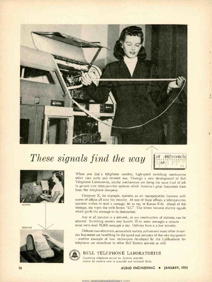
These signals find the way
SENDING
RECEIVING
m* DVGW<OKAN 00 00 o o o 0 0 0 o o 0 ; »#» >>j' D
D J DD
When you dial a telephone number, high -speed switching mechanisms select your party and connect you. Through a new development of Bell Telephone Laboratories, similar mechanisms are doing the same kind of job in private wire teletypewriter systems which America's great businesses lease from the telephone company.
Company X, for example, operates an air transportation business with scores of offices all over the country. At one of these offices, a teletypewriter operator wishes to send a message, let us say, to Kansas City. Ahead of the message, she types the code letters "KC ". The letters become electric signals which guide the message to its destination.
Any or all stations in a network, or any combination of stations, can be selected. Switching centers may handle 50 or more messages a minute . . .
some users send 30,000 messages a day. Delivery time is a few minutes.
Defense manufacturers, automobile makers. airlines and many other Ameri- can businesses are benefiting by the speed and accuracy of the new equipment - another example of how techniques developed by the Laboratories for telephone use contribute to other Bell System services as well.
18
BELL TELEPHONE LABORATORIES Improving telephone service for America provides careers for creative men in scientific and technical fields.
AUDIO ENGINEERING JANUARY, 1953
1
www.americanradiohistory.comAmericanRadioHistory.Com
Practical Aspects of the R -J Speaker Enclosure
WILLIAM JOSEPH and FRANK ROBBINS'
A further discussion of the enclosure which has created so much interest and which was the forerunner of the current flurry for small cabinets.
CDMMERCIAL HIGH- FIDELITY reproduc- ing equipment has for some time been available at prices low enough
to permit widespread use in home instal - tions. Tuners, amplifiers, cartridges, and speakers which can handle the range from 50 to 10,000 cps are today quite reasonably priced, and equipment hand- ling 30 to 15,000 cps is available in the higher -price range. Speaker develop- ment has reached the stage where the former range can now be handled by single -cone speakers and the latter by two- or three -way speaker systems. Most of the progress taking place in speaker development over the last decade has been mainly in extension of the treble range, since low bass reproduction in speaker techniques preceded the develop- ment in the treble range.
Reproduction of the low bass end, however, is a function not only of the speaker but of speaker enclosure as well. As almost all 12- and 15 -in. speakers designed for the high -fidelity market are capable of reproducing down to 50 cps and below, the responsibility for low bass reproduction today rests almost en- tirely on the enclosure. Unfortunately, space limitations in the modern home mitigate against the use of large en- closures and in most home systems the octave below 100 cps is generally miss- ing or is strongly curtailed. While such systems would sound balanced and pleas- ing before the full treble range became available -and do indeed sound better if the amplifier treble control is cut back - it is generally found today that home systems are operated with the treble control flat and with the bass control considerably boosted in an attempt to improve balance. While this boost in the 100- to 200 -cps range may help matters somewhat, there is actually no true bass "feeling" to such reproduction. It was considered worthwhile, therefore, to attempt to develop a small enclosure which would permit extending the bass range to at least 50 cps, and if possible to attempt to attain this result without resonant peaks, yet with good damping and transient response. Resonant peaks in the bass range produce "boom" and "barrelly" speech reproduction, while poor transient response "muddies up" the bass.
* 5218 19th Ave., Brooklyn 4, N. Y. ** 10 West 86th St., New York 24, N. Y.
A brief consideration o_ existing sys- tems required to provide 53-cps response will -be pertinent in tracing the develop- ment of the R -J system and the follow- ing types of speaker housings will be considered:
1. Flat Baffle 2. Open -back Box 3. Closed Box 4. Horns 5. Bass Reflex 6. The R -J Enclosure
The Flat Baffle
To reproduce 50 cps adequately, a flat baffle must be eleven feet square. If the speaker itself resonates at 50 cps, there will be a hump in pressure -response curve at this frequency and the response will fall off below this point at the rate of 18 db per octave.
The Open -Back Box
Open -back boxes are not suitable. A 7 -cu. ft. open -back box 4 in. from the wall produces a wallopi-tg "boom" at 100 cps' and response drops off below at the rate of 18 db per octave. Below 100 cps, frequency -doubling and tripling is extremely objectionable.
Closed Boxes and Horns
Completely enclosed boxes need to be very large. A 15 -in. speaker will require
1 Daniel Plach and Philip Williams, "Loudspeaker enclosures." AUDIO ENGI- NEERING, July 1951.
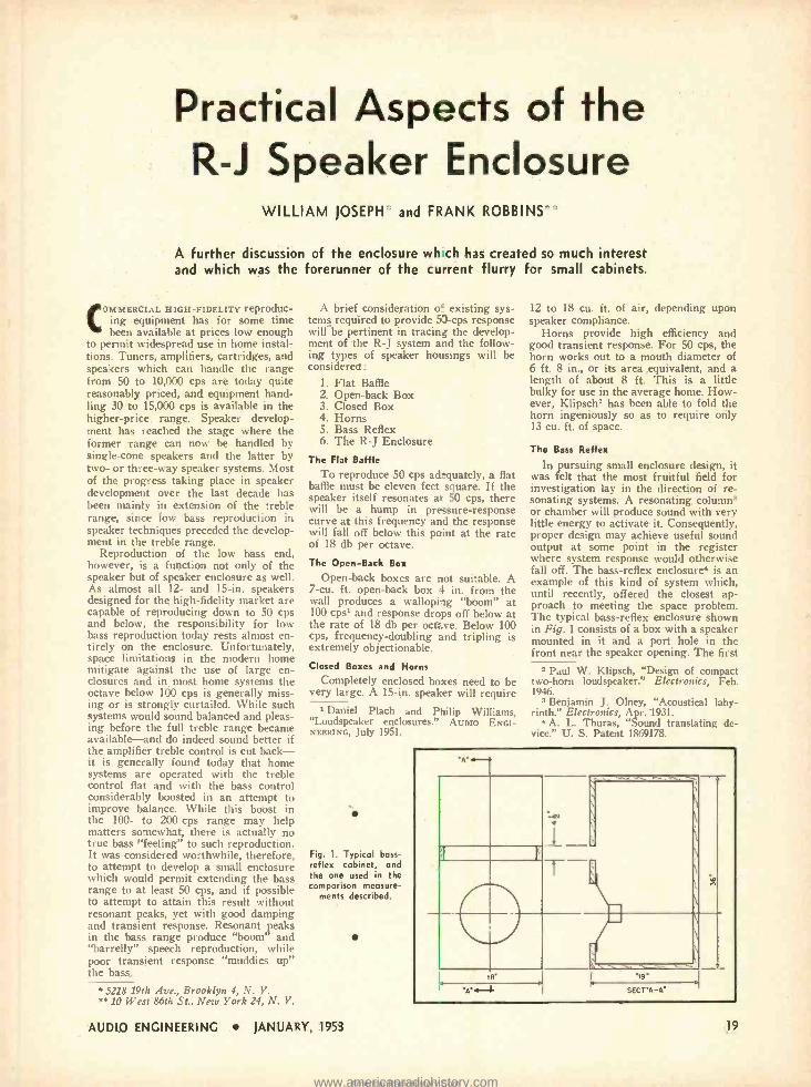
Fig. 1. Typical bass - reflex cabinet, and the one used in the comparison measure-
ments described.
AUDIO ENGINEERING JANUARY, 1953
12 to 18 cu. ft. of air, depending upon speaker compliance.
Horns provide high efficiency and good transient response. For 50 cps, the horn works out to a mouth diameter of 6 ft. 8 in., or its area equivalent, and a length of about 8 ft. This is a little bulky for use in the average home. How- ever, Klipsch2 has been able to fold the horn ingeniously so as to require only 13 cu. ft. of space.
The Bass Reflex
In pursuing small enclosure design, it was felt that the most fruitful field for investigation lay in the direction of re- sonating systems. A resonating columns or chamber will produce sound with very little energy to activate it. Consequently, proper design may achieve useful sound output at some point in the register where system response would otherwise fall off. The bass -reflex enclosure' is an example of this kind of system which, until recently, offered the closest ap- proach to meeting the space problem. The typical bass -reflex enclosure shown in Fig. 1 consists of a box with a speaker mounted in it and a port . hole in the front near the speaker opening. The first
2 Paul W. Klipsch, "Design of compact two -horn loudspeaker." Electronics, Feb. 1946.
s Benjamin J. Olney, "Acoustical laby- rinth." Electronics, Apr. 1931.
4 A. L. Thuras, "Sound translating de- vice." U. S. Patent 1869178.
'19'
SEC T'A -A'
19
www.americanradiohistory.comAmericanRadioHistory.Com
step in the design of the enclosure re- quires that the air resonance of the box occurs at the free -air cone resonance of the speaker.
The air resonance of the bass -reflex enclosure can be closely determined:
c (,q) %
2a (V)' where A = the area of the port
V = the volume of the enclosure c = the speed of sound in air
This bass reflex cabinet, later used as a comparison enclosure, employs a 12 -in. speaker with a free -air cone resonance of 63 cps. To determine the volume V required, the formula may be rearranged to read
(1)
V =2070 [(`--41% (2)
where V is in cu in.- A is in sq in. f is in cycles per second.
Using A of 75 sq. in. and f of 63 cps, V comes out to be 9400 cu. in. Adding another 400 cu: in. for the speaker, the total internal volume required is 9800 cu. in. or 5.7 cu. ft.
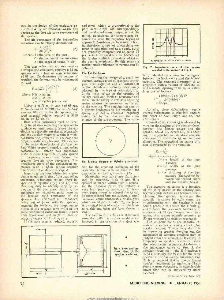
Bass reflex enclosures must be care- fully tuned after mounting the speaker to produce optimum results. Since the en- closure is generally purchased separately and the speaker mounted within it with- out further adjustments, it is seldom that proper results are obtained. This is one of the major drawbacks of the bass re- flex. When properly tuned, a bass -reflex enclosure will exhibit two impedance peaks of equal amplitude, equally spaced in frequency above and below the speaker free -air cone resonance. The impedance curve of the comparison en- closure with a 12 -in. 8-ohm speaker mounted in it is shown in Fig. 2.
Exploring the possibilities for appre- ciable reduction in size of the bass -reflex enclosure, it becomes evident from in- spection of equations (1) and (2) that this may only be accomplished by re- duction of the port area. Basically, the enclosure air resonance must occur at the free -air cone resonance of the speaker. The enclosure air resonance, being out of -phase with the speaker, restricts the tendency for large move- ments of the speaker cone while at the same time sound radiation from the port area takes over and helps to provide acoustic output at this frequency.
If the port area is reduced, acoustic
radiation -which is proportional to the port area -drops off correspondingly and the desired sound output is not ob- tained. In addition, if the port area be- comes too small the enclosure begins to approach closed -box performance. There is, therefore, a law of diminishing re- turns in operation and as a result, ports are generally compromised to about 75 per cent of the speaker area. Sometimes the further addition of a duct added to the port is employed. By this means a further small reduction in volume can be obtained.
The R -1 Enclosure
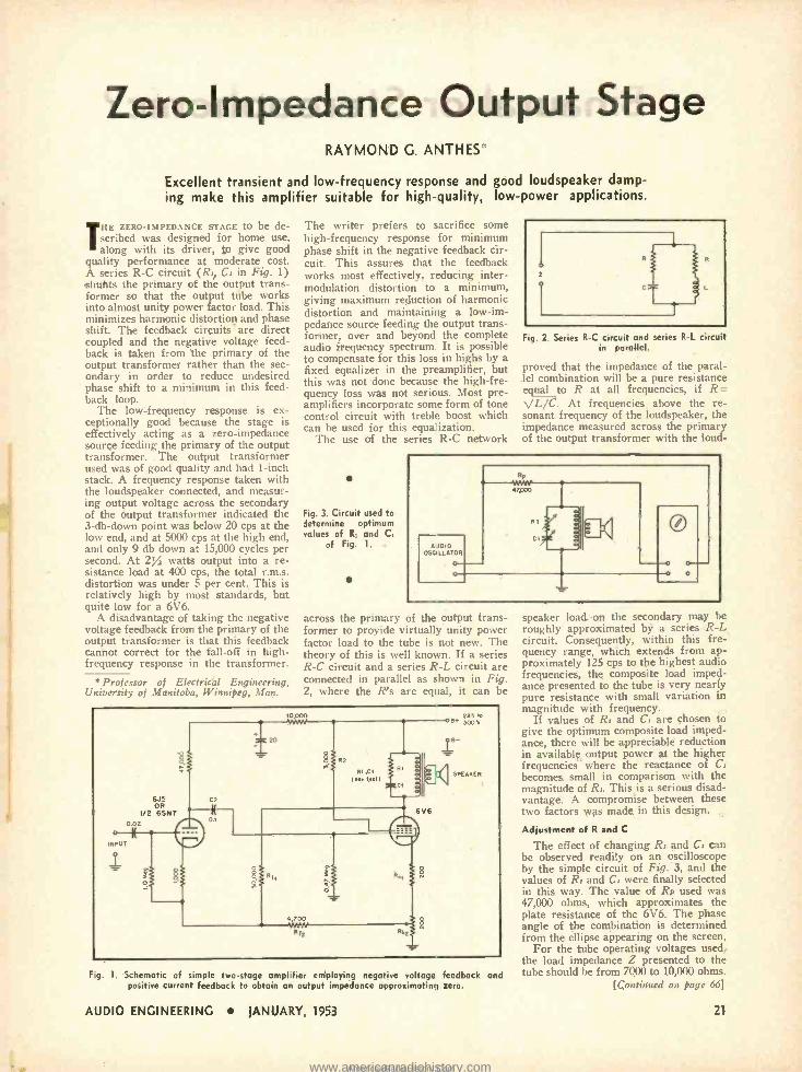
In pursuing the design of a small en- closure, various types of resonant princi- ples were explored and an adaptation of the Helmholtz resonator was finally adopted. In this type of resonator, Fig. 3, the mass of air in the opening A swings back and forth at resonance and the air in the cavity V acts as a resisting spring against the movement of the air in the opening. The combination sets up a system analogous to the weight on a spring and has a resonant frequency determined by the mass and the com- pliance of the arrangement. The equa-
Fig. 3. Basic diagram of Helmholtz resonator.
tion for the resonant frequency of the resonator is the same as that for the bass -reflex enclosure, equation (1).
Helmholtz resonators are character- ized by extremely high Q and if a speaker is placed within such a resona- tor the response curve will exhibit a very high peak at resonance. If, how- ever, some means to control the Q can be incorporated into the system, a small enclosure could conceivably be designed which would permit flattening the peak. A practical form of enclosure which at- tains this end takes the form shown in Fig. 4.
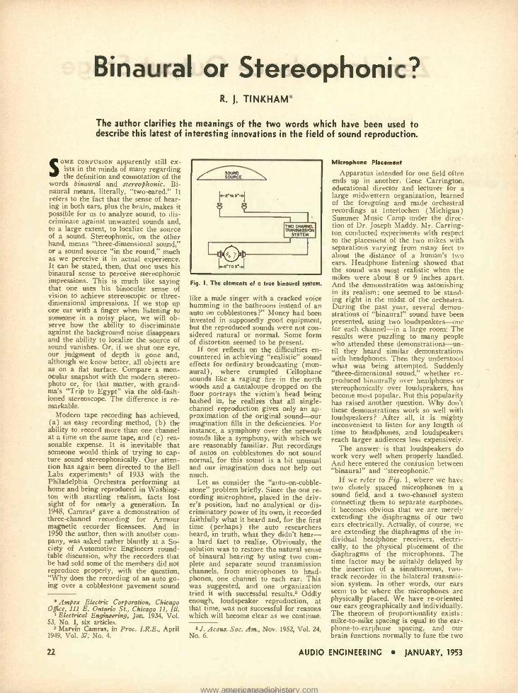
The system still acts as a Helmholtz resonator with the further modification imposed by the creation of a duct sys-
2 s SECT 'A-A
20
Fig. 4. Front and sec- tional views of R -1 speaker enclosure.
á
(-
FREQUENCY IN CYCLES KR SECOND
Fig. 2. Impedance curve of the speaker mounted in the cabinet of Fig. 1.
tern, indicated by arrows in the figure, between the back cavity and the frontal opening. The resonant frequency of an enclosure with a volume of 4800 -cu. in. and a frontal opening of 64 sq. in. calcu- lates out as follows : .
(1080x12) x (64)% f- 2n (4800)%
= 84 cps.
Actually, close calculations require several refinements to take into account the effect of duct length and the end corrections.
Control of the circuit Q is obtained by varying the spacing of the duct produced between the frontal board and the speaker board. By decreasing this spac- ing it is possible to introduce acoustic resistance to lower the Q and increase damping. The acoustical resistance of a slot is expressed by the equation :
tRa = 'w
where k = a constant l = the length of the duct
passage w = the width of the duct
passage t = the thickness of the duct
passage (the spacing be- tween the frontal board and the speaker board.
The acoustic resistance is a function of the third power of the spacing and becomes quite critical as t becomes small. Halving the spacing increases the acoustic resistance by eight times. By experimenting with the spacing it was found possible to reduce the circuit Q and broaden the resonance so that with a speaker of 63 cps free -air cone reso- nance, this system extends smoothly to 50 cps without any peak at resonance.
The introduction of the acoustic re- sistance also has a strong effect upon speaker loading. This is very desirable in improving speaker damping and the magnitude of damping obtained may be judged from the amount of lowering in frequency of speaker resonance below the free -air cone resonance. As shown in the impedance curve of Fig. 5, the speaker resonance in the R -J enclosure is 32. cps, as against 50 cps for the same speaker in the bass -reflex enclosure, Fig. 2. It is believed that a 32 -cps loaded speaker resonance, as against a 63 -cps free -air cone resonance, is considerably lower than can be achieved by other systems.
[Continued on page 67]
AUDIO ENGINEERING JANUARY, 1953
www.americanradiohistory.comAmericanRadioHistory.Com
Zero -Impedance Output Stage RAYMOND G. ANTHES
Excellent transient and low- frequency respcnse and good loudspeaker damp- ing make this amplifier suitable for high- quality, low -power applications.
THE ZERO -IMPEDANCE STAGE to be de- scribed was designed for home use, along with its driver, to give good
quality performance at moderate cost. A series R -C circuit (R,, C, in Fig. 1) huhts the primary of the output trans- former so that the output tube works into almost unity power factor load. This minimizes harmonic distortion and phase shift. The feedback circuits are direct coupled and the negative voltage feed- back is taken from the primary of the output transformer rather than the sec- ondary in order to reduce undesired phase shift to a minimum in this feed- back loop.
The low- frequency response is ex- ceptionally good because the stage is effectively acting as a zero -impedance source feeding the primary of the output transformer. The output transformer used was of good quality and had 1 -inch stack. A frequency response taken with the loudspeaker connected, and measur- ing output voltage across the secondary of the output transformer indicated the 3 -db -down point was below 20 cps at the low end, and at 5000 cps at the high end, and only 9 db down at 15,000 cycles per second. At 2% watts output into a re- sistance load at 400 cps, the total r.m.s. distortion was under 5 per cent. This is relatively high by most standards, but quite low for a 6V6.
A disadvantage of taking the negative voltage feedback from the primary of the output transformer is that this feedback cannot correct for the fall -off in high - frequency response in the transformer.
Professor of Electrical Engineering, University of Manitoba, Winnipeg, Man.
The writer prefers to sacrifice sonic high -frequency response for minimum phase shift in the negative feedback cir- cuit. This assures that the feedback works most effectively, reducing inter - modulation distortion to a minimum, giving maximum reduction of harmonic distortion and maintaining a low -im- pedance source feeding the output trans- former, over and beyond the complete audio frequency spectrum. It is possible to compensate for this loss in highs by a fixed equalizer in the preamplifier, but this was not done because the high -fre- quency loss was not serious. Most pre- amplifiers incorporate some form of tone control circuit with treble boost which can be used for this equalization.
The use of the series R -C network
Fig. 3. Circuit used to determine optimum values of R, and C,
of Fig. 1.
Fig. 2. Series R -C circuit and series R -L circuit in parallel.
proved that the impedance of the paral- lel combination will be a pure resistance equal to R at all frequencies, if R. ',/L /C /C. At frequencies above the re- sonant frequency of the loudspeaker, the impedance measured across the primary of the output transformer with the loud-
across the primary of the output trans- former to provide virtually unity power factor load to the tube is not new. The theory of this is well known. If a series R -C circuit and a series R -L circuit are connected in parallel as shown in Fig. 2, where the R's are equal, it can be
0.02
6J5 OR
1/2 65N7
10.000 285 ,e B 300,
PEAK( R
4,700
Rf2
Fig. 1. Schematic of simple two -stage amplifier employing negative voltage feedback and positive current feedback to obtain an output impedance approximating zero.
speaker load on the secondary may be roughly approximated by a series R -L circuit. Consequently, within this fre- quency range, which extends from ap- proximately 125 cps to the highest audio frequencies, the composite load imped- ance presented to the tube is very nearly pure resistance with small variation in magnitude with frequency. ..
If values of R, and C, are chosen to give the optimum composite load imped- ance, there will be appreciable reduction in available, output power at the higher frequencies where the reactance of C, becomes small in comparison with the magnitude of R. This is a serious disad- vantage. A compromise between these two factors was made in this design.
Adjustment of R and C
The effect of changing R, and C. can be observed readily on an oscilloscope by the simple circuit of Fig. 3, and the values of R, and C, were finally selected in this way. The value of Rv used was 47,000 ohms, which approximates the plate resistance of the 6V6. The phase angle of the combination is determined from the ellipse appearing on the screen.
For the tube operating voltages used, the load impedance Z presented to the tube should be from 7000 to 10,000 ohms.
[Continued on page 66]
AUDIO ENGINEERING JANUARY, 1953 21
www.americanradiohistory.comAmericanRadioHistory.Com
Binaural or Stereophonic? R. J. TINKHAM'
The author clarifies the meanings of the two words which have been used to describe this latest of interesting innovations in the field of sound reproduction.
SOuse CONFUSION apparently still ex- ists in the minds of many regarding the definition and connotation of the
words binaural and stereophonic. Bi- naural means, literally, "two- eared." It refers to the fact that the sense of hear- ing in both ears, plus the brain, makes it possible for us to analyze sound, to dis- criminate against unwanted sounds and, to a large extent, to localize the source of a sound. Stereophonic, on the other hand, means "three- dimensional sound," or a sound source "in the round," much as we perceive it in actual experience. It can be stated, then, that one uses his binaural sense to perceive stereophonic impressions. This is much like saying that one uses his binocular sense of vision to achieve stereoscopic or three - dimensional impressions. If we stop up one ear with a finger when listening to someone in a noisy place, we will ob- serve how the ability to discriminate against the background noise disappears and the ability to localize the source of sound vanishes. Or, if we shut one eye, our judgment of depth is gone and, although we know better, all objects are as on a flat surface. Compare a mon- ocular snapshot with the modern stereo - photo or, for that matter, with grand- ma's "Trip to Egypt" via the old -fash- ioned stereoscope. The difference is re- markable.
Modern tape recording has achieved, (a) an easy recording method, (b) the ability to record more than one channel at a time on the same tape, and (c) rea- sonable expense. It is inevitable that someone would think of trying to cap- ture sound stereophonically. Our atten- tion has again been directed to the Bell Labs experiments' of 1933 with the Philadelphia Orchestra performing at home and being reproduced in Washing- ton with startling realism, facts lost sight of for nearly a generation. In 1948, Camras2 gave a demonstration of three- channel recording for Armour magnetic recorder licensees. And in 1950 the author, then with another com- pany, was asked rather bluntly at a So- ciety of Automotive Engineers round- table discussion, why the recorders that he had sold some of the members did not reproduce properly, with the question, "Why does the recording of an auto go- ing over a cobblestone pavement sound
* Ampex Electric Corporation, Chicago Office, 111 E. Ontario St., Chicago 11, Ill.
'Electrical Engineering, Jan. 1934, Vol. 53, No. 1, six articles.
2 Marvin Camras, in Proc. I.R.E., April 1949, Vol. 37, No. 4.
Fig. 1. The elements of a true binaural system.
like a male singer with a cracked voice humming in the bathroom instead of an auto on cobblestones ?" Money had been invested in supposedly good equipment, but the reproduced sounds were not con- sidered natural or normal. Some form of distortion seemed to be present.
If one reflects on the difficulties en- countered in achieving "realistic" sound effects for ordinary broadcasting (mon- aural), where crumpled Cellophane sounds like a raging fire in the north woods and a cantaloupe dropped on the floor portrays the victim's head being bashed in, he realizes that all single - channel reproduction gives only an ap- proximation of the original sound -our imagination fills in the deficiencies. For instance, a symphony over the network sounds like a symphony, with which we are reasonably familiar. But recordings of autos on cobblestones do not sound normal, for this sound is a bit unusual and our imagination does not help out much.
Let us consider the "auto-on- cobble- stone" problem briefly. Since the one re- cording microphone, placed in the driv- er's position, had no analytical or dis- criminatory power of its own, it recorded faithfully what it heard and, for the first time (perhaps) the auto researchers heard, in truth, what they didn't hear - a hard fact to realize. Obviously, the solution was to restore the natural sense of binaural hearing by using two com- plete and separate sound transmission channels, from microphones to head- phones, one channel to each ear. This was suggested, and one organization tried it with successful results .3 Oddly enough, loudspeaker reproduction, at that time, was not successful for reasons which will become clear as we continue.
s J. Acous. Soc. Am., Nov. 1952, Vol. 24, No. 6.
Microphone Placement
Apparatus intended for one field often ends up in another. Gene Carrington, educational director and lecturer for a large midwestern organization, learned of the foregoing and made orchestral recordings at Interlochen (Michigan) Summer Music Camp under the direc- tion of Dr. Joseph Maddy. Mr. Carring- ton conducted experiments with respect to the placement of the two mikes with separations varying from many feet to about the distance of a human's two ears. Headphone listening showed that the sound was most realistic when the mikes were about 8 or 9 inches apart. And the demonstration was astonishing in its realism; one seemed to be stand- ing right in the midst of the orchestra. During the past year, several demon- strations of "binaural" sound have been presented, using two loudspeakers-one for each channel -in a large room. The results were puzzling to many people who attended these demonstrations-un - til they heard similar demonstrations with headphones. Then they understood what was being attempted. Suddenly "three- dimensional sound," whether re- produced binaurally over headphones or stereophonically over loudspeakers, has become most popular. But this popularity has raised another question. Why don't these demonstrations work so well with loudspeakers ? After all, it is mighty inconvenient to listen for any length of time to headphones, and loudspeakers reach larger audiences less expensively.
The answer is that loudspeakers do work very well when properly handled. And here entered the confusion between "binaural" and "stereophonic."
If we refer to Fig. 1, where we have two closely spaced microphones in a sound field, and a two -channel system connecting them to separate earphones. it becomes obvious that we are merely extending the diaphragms of our two ears electrically. Actually, of course, we are extending the diaphragms of the in- dividual headphone receivers, electri- cally, to the physical placement of the diaphragms of the microphones. The time factor may be suitably delayed by the insertion of a simultaneous, two - track recorder in the bilateral transmis- sion system. In other words, our ears seem to be where the microphones are physically placed. We have re- oriented our ears geographically and individually. The theorem of proportionality exists: mike -to -mike spacing is equal to the ear - phone-to- earphone spacing, and our brain functions normally to fuse the two
22 AUDIO ENGINEERING JANUARY, 1953
www.americanradiohistory.comAmericanRadioHistory.Com
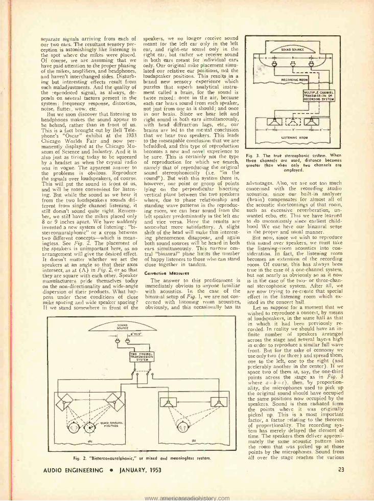
separate signals arriving from each of our two ears. The resultant sensory per- ception is astonishingly like listening in the spot where the mikes were placed. Of course, we are assuming that we have paid attention to the proper phasing of the mikes, amplifiers, and headphones, and haven't interchanged sides. Disturb- ing but interesting effects result from such maladjustments. And the quality of the reproduced signal, as always, de- pends on several factors present in the system: frequency response, distortion, noise, flutter, wow, etc.
But we soon discover that listening to headphones makes the sound appear to be behind, rather than in front of us. This is a fact brought out by Bell Tele- phone's "Oscar" exhibit at the 1933 Chicago Worlds Fair and now per- manently displayed at the Chicago Mu- seum of Science and Industry. And it is also just as tiring today to be squeezed by a headset as when the crystal radio was in vogue. The apparent answer to the problems is obvious. Reproduce the signals over loudspeakers, of course. This will put the sound in front of us, and will be more convenient for listen- ing. But while the sound as we hear it from the two loudspeakers sounds dif- ferent from single channel listening, it still doesn't sound quite right. Remem- ber, we still have the mikes placed only 8 or 9 inches apart. We have suddenly invented a new system of listening: "bi- stereonauralphonic" or a cross between two different concepts -which is mean- ingless. See Fig. 2. The placement of the speakers is unimportant here, as no arrangement will give the desired effect. It doesn't matter whether we set the speakers at an angle so that their axes intersect, as at (A) in Fig. 2, or so that they are square with each other. Speaker manufacturers pride themselves today on the non -directionality and wide -angle dispersion of their products. What hap- pens under these conditions of close mike spacing and wide speaker spacing? Tf we stand somewhere in front of the
speakers, we no longer receive sound meant for the left ear only in the left ear, and right -ear sound only in the right ear, but rather we receive sound in both ears meant for individual ears only. Our original mike placement simu- lated our relative ear positions, not the loudspeaker positions. This resulte in a brand new sensory experience which puzzles that superb analytical instru- ment called a brain, for the sound is twice mixed: once in the air, because each ear hears sound from each speaker, not just from one as it should; and once in our brain. Since we hear left and right sound in both ears simultaneously, with head diffraction lags, etc., our brains are led to the mental conclusion that we hear two speakers. This leads to the inescapable conclusion that we are befuddled, and this type of reproduction becomes a new and novel experience to be sure. This is certainly not the type of reproduction for which we search, namely that of reproducing the original sound stereophonically (i.e. "in the round "). But with this system there is, however, one point or group of points lying on the perpendicular bisecting vertical plane between the two speakers where, due to phase relationship and standing wave patterns in the reproduc- ing room, we can hear sound from the left speaker predominantly in the left ear and vice versa. Here the results are somewhat more satisfactory. A slight shift of the head will make this interest- ing phenomenon disappear, and again both sound sources will be heard in both ears simultaneously. This narrow cen- tral "binaural" plane limits the number of happy listeners to those who can stand close together in tandem.
Corrective Measures
The answer to this predicament is immediately obvious to anyone familiar with acoustics. In the case of the binaural setup of Fig. 1, we are not con- cerned with listening room acoustics, obviously, and this occasionally has its
SOUND SOURCE
191
Fig. 2. "Bistereonauralphonic," or mixed and meaningless syst:m.
/ SOUND SOURCE
RECDRDING ROOM
MULTIPLE CHANNEL TRANSMISSION OR RECORDING SYSTEM
x, .. a--a' pl. r-t.
LISTENING ROOM
Fig. 3. The tru_ stereophonic system. When three channels are used, distance becomes greater than when only two channels are
employed.
advantages. Also, we are not too much concerned with the recording studio acoustics, since our built -in analyzer (brain) compensates for almost all of the acoustic shortcomings of that room, such as excessive reverberation, un- wanted echo, etc. This we have learned to do unconsiously since earliest child- hood We use here our binaural sense in the proper and usual manner.
But now, since we wish to reproduce this sound over speakers, we must take the listening -room acoustics into con- sideration. In fact, the listening room becomes an extension of the recording room. Of course, this has always been true in the case of a one -channel system, but not nearly as obviously so as it now is in the case of the two- or three -chan- nel stereophonic system. After all, we are now trying to re- create that special effect in the listening room which ex- isted in the concert hall.
Let us suppose for a moment that we wished to reproduce a concert, by means of loudspeakers, in the same hall as that in which it had been previously re- corded. In reality we should have an in- finite number of speakers arraned across the stage and several layers high in order to reproduce a similar full wave front. But for the sake of economy we use only two (or three) and spread them, one to the left, one to the right (and preferably another in the center). If we space two of them at, say, the one -third points across the stage as in Fig. 3 where a = b = c), then, by proportion- ality, the microphones used to pick up the original sound should have occupied the same positions now occupied by the speakers. Sound is then radiated from the points where it was originally picked up. This is a most important factor, a factor relating to the theorem of proportionality. The recording sys- tem has merely delayed the element of time. The speakers then deliver approxi- mately the same acoustic pattern into the room that was picked up at those points by the microphones. Sound from all over the stage reaches the various
AUDIO ENGINEERING JANUARY, 1953 23
www.americanradiohistory.comAmericanRadioHistory.Com
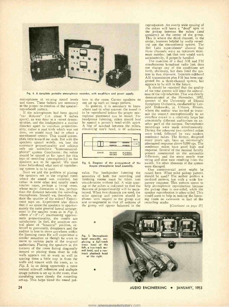
Fig. 4. A complete portable stereophonic
microphones at varying sound levels and times. These factors are necessary to the proper re- creation of the speaker - reproduced pattern.
If the microphones had been spaced "ear distance" (i.e. about 9 inches apart), as was done in a recent demon- stration, and the loudspeakers a similar distance apart to maintain proportion- ality, rather a neat trick which was not done, we would have had in effect a one -channel system. This would accom- plish little toward our ends. But with the speakers spaced widely, we lose the necessary proportionality and achieve only our unrealistic "bistereonaural - phonic" system. Conclusion: the mikes should be spaced as far apart for this type of recording (stereophonic) as the speakers are to be spaced. We must know beforehand what sort of reproduc- ing system is to be used.
Next we add the problem of placing the speakers not in the original room where the sound was recorded, but rather in some other and usually much smaller room, perhaps a living room, whose major dimension is less, perhaps than the distance between the recording microphones. Should we, therefore, re- duce the spacinv of the mikes? Experi- ment says no. Experiment also shows that if we space the speakers in approxi- mately the same general lateral arrange- ment in the smaller room as in Fig. 3, where a' = b' = c', maintaining approxi- mate proportionality, the results are satisfactory.' In fact, the sensitive cen- tral plane of "binaural" position, re- ferred to previously, disappears and the auditor is free to move anywhere within the listening room He will experience a similar sensation as though he were to move to various parts of the original auditorium. Placing the speakers in the corners of the room facing diagonally inward or placing them close to side walls appears not to work as well as spacing them a little way in from the walls and square with the room, as in Fig. 3. In so doing apparently a more normal sidewall reflection and multiple image pattern is set up in the room, thus simulating more closely the recording set -up. This helps blend the sound pat-
24
recorder, with amplifiers and power supply.
tern in the room. Corner speakers do not set up such an image pattern.
In general, it is necessary to know where and in what manner the sound is to be reproduced before the proper mic- rophone placement can be stated. For headphone listening, mikes should best be spaced a person's head -width apart. A bag of sawdust between the mikes, simulating one's head, is of unknown
m TAPE
Q.7
RECORD RECORD
PLAYBACK PLAYBACK
Fig. 6. Diagram of th" arrangement of the Ampex stereophonic head assembly.
value. For loudspeaker listening the acoustics of both the recording and listening rooms must be taken into consideration without fail. A wide spac- ing of the mikes is indicated so that the theorem of proportionality will be main- tained. When two channels are used, the mike spacing and position should be chosen with respect to the group size and arrangement so that all sections of the group will appear balanced in the
e
Fig. 5. Stereophonic head assembly, em- ploying a full -track erase head at the left, a two -track rec- ord head, and a two - track playback head
at the right.
reproduction. An overly wide spacing of the mikes will leave. a "dead" spot in the pickup between the mikes (and speakers) at the center of the group. This is where the third channel, in the center, becomes helpful by really round- ing out the stereophonic system. The Bell Labs experiments' showed that three channels were an optimum mini- mum number, but that two would work satisfactorily, if properly handled.
The insertion of a dual AM and FM simultaneous broadcast radio link does not change any of the conditions set forth, obviously, but does limit the sys- tem to two channels. Separate- sideband AM transmission plus FM has been sug- gested for a three -channel system, but appears to be still in the future.
It should be repeated that the quality of the total system will limit the natural- ness of the reproduction. This was clearly demonstrated' at the November, 1952, concert of the University of Illinois Symphony Orchestra, conducted by Leo- pold Stokowski, at Urbana, Illinois, where the author was invited to trans- mit the concert stereophonically to an overflow crowd in a relatively large but acoustically different auditorium on an- other part of the campus. Stereophonic recordings were made simultaneously. During the rehearsal two cardioid mikes were tried, followed by two modern condenser mikes. The former, designed many years ago, have an increasingly attenuated response above 9,000 cps. The condenser mikes have good high end response. Several of the musical faculty present commented on the noticeable difference, and the more nearly true string and oboe tone resulting from the switch. No other elements of the system were changed.
One controversial point might be raised here. What mike pickup pattern should be used? The author prefers a cardioid pattern, but with a wide fre- quency response. This pattern seems to help stereophonic reproduction because the pickup thus is one -sided, while the speaker reproduction is other -sided. This would seem to help in making the listen- ing room an extension in fact of the recording studio.
[Continued on page 571
AUDIO ENGINEERING JANUARY, 1953
www.americanradiohistory.comAmericanRadioHistory.Com
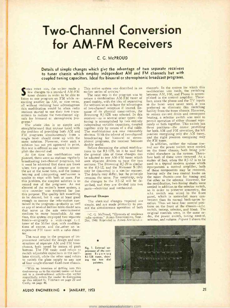
Two -Channel Conversion for AM -FM Receivers
C. G. McPROU)
Details of simple changes which give the advantage of two separate receivers to tuner chassis which employ independent AM and FM channels but with coupled tuning capacitors. Ideal for binaural or stereophonic broadcast programs.
SOME TIME AGO, the writer made a few changes to a standard AM -FM tuner chassis in order to be able to
listen to one program on FM while re- cording another on AM, or vice versa, all without realizing how advantageous this modification would be when radio stations started to use their two trans- mitters to radiate the two- channel sig- nals for binaural or stereophonic pro- grams.'
The whole idea is so simple and straightforward that anyone faced with the problem of providing both AM and FM programs simultaneously from a single tuner should come up with the same solution. However, since such a solution has not yet appeared in print, this one is offered as one way to accom- plish the desired end.
At the time the modification was planned, there were no stations regularly broadcasting two -channel programs, but it must be admitted that there are times when two programs of interest are on the air at the same time, and the human hearing and interpreting mechanism is unable to cope with both at once. For this problem, the simplest solution is to record one of the programs. As one element of the writer's home system, a wire recorder was employed for just this purpose. The quality left something to be desired, but it was at least good enough to convey the information con- tained in the program -probably as well as any of several million table -model sets that serve as the sole entertainment medium in many households. At one time, this system employed two separate tuners -originally a wide -range t.r.f. tuner of the Miller type, with modifica- tions of course, and the _other an in- expensive FM tuner with a ratio detec- tor.
The next step in the program of im- provement included the design and con- struction of separate AM and FM tuner chassis, both tuned by means of push buttons. The FM tuner used relays to switch adjustable capacitors in the oscil- lator circuit, while the other used relays to switch the plate supply to any one of four single -channel fixed -tune chassis.
i With no intention of getting into this controversy as to the correct name -at least not in a constructional article -the writer respectfully refers the reader to discussions on this subject by Tinkham on page 22 and Canby on page 46. .
This entire system was described in an earlier series of articles.-
The next step in the program was to secure a combination AM -FM tuner of good quality, with the idea of separating the sections so as to have the advantages of two- channel reception if desired. Be- cause of its physical construction, the Browning RJ -12B was selected. In this receiver -as in several other types -the tuning is accomplished by two entirely independent variable capacitors, coupled together only by means of a dial cable. The modifications are now reasonably obvious. With the advent of two -channel broadcasting for binaural or stereo- phonic programs, the receiver becomes doubly useful.
Before discussing the acttal modifica- tions to the RJ -12B, let it be said that the general idea of these changes can be adapted to any AM -FM tuner which uses separate devices to tune the two sections. The Browning RJ -20 is similar to the RJ -12, and the Meissner 9 -1091 may be converted in a sim lar manner. The details may differ, but the principle remains the same. For simplicity, only the changes to the RJ -12 will be de- scribed, and they are divided into two parts -electrical and mechanical.
Electrical Changes
The electrical changes required are simple, and are made primarily to per- mit the simultaneous operation of both
2 C. G. McProud, "Element, of residence radio systems." AUDIO ENGINEERING, Sept. - Dec. 1948. Reprinted in AUDIO ANTIIr'I.O::Y.
Fig. 1. External ap- pearance of tic con- verter Browning RJ -12B tuner, show- ing the two dial
pointers.
AUDIO ENGINEERING JANUARY, 1953
o
channels. In the system for which this modification was made, the switching between AM, FM, and Phono is accom- plished in the control amplifier. There- fore, since the phono and the TV inputs to the tuner were never used, it was preferred to eliminate this switching facility from the tuner chassis. However, to reduce current drain and consequent heating, a selector switch was used to permit operation of either channel sepa- rately or both together. This switch has three positions -the center providing for both AM and FM operation, the left position energizing only the AM tuner, and the right position energizing only the FM tuner.
In addition, neither the volume con- trol nor the power switch were needed on the tuner chassis, both being pro- vided elsewhere in the system. There- fore both of these were removed. As a matter of fact, when the RJ -12 is to be used in a typical modern system which incorporates a control amplifier, both of these components may be removed, leaving only the two central knobs on the tuner chassis -one for tuning and the other as the selector. However, for the modification, two tuning shafts were needed in addition to the selector switch, so in order to preserve symmetry, the a.f.c. switch was wired to the front panel, which is somewhat more con- venient than its normal back -apron lo- cation. Thus we have four control posi- tions on the front of the chassis- a.f.c. switch, tuning, selector, and blank. The original controls were, in the same or- der, the power switch, tuning control, selector, and volume. Figure 1 shows the
25
www.americanradiohistory.comAmericanRadioHistory.Com
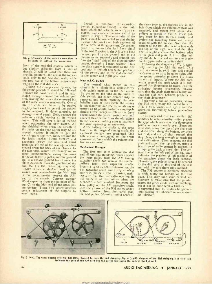
To a -M ose
o
ro
F.M 05C
G M 60. F M 0 OnIIO G'^ r
c
G.
Fig. 2. Schematic of the switch connections to be made in making the conversion.
front of the modified chassis, which is but slightly different from a normal chassis. It will be noted that there are two dial pointers -the one at the top ex- tends only to the AM dial scale, while the new one at the bottom extends up- wards to the FM dial scale.
Taking the changes one by one, the following procedure should be followed. Remove the power switch and its asso- ciated wiring. Remove the volume con- trol, leaving the wires disconnected but at the same location temporarily. One of the r.f. coils will have to be pushed slightly backward to permit the control to be removed. If done carefully, no damage should result. Now, remove the selector switch, leaving all its wiring intact. This will save a lot of tracing when connecting the new switch. All the shielded wires from the switch to the jacks on the rear apron may he re- moved, making it easier to get the switch out of the way. Next, remove the tip jacks marked AUDIO OUTPUT and RECORDER INPUT -the first and third from the left end of the rear apron when viewed from the back of the chassis. In the two holes, mount two 1.0 -meg audio - taper potentiometers, wiring the arms to the adjacent tip jacks, and the ground end to a chassis ground lead. Connect a .05 -uf capacitor from the junction of R and R (in the Browning diagram) -from which a shielded lead to the switch was removed -to the high end of the potentiometer nearest the AM end of the chassis. Connect another .05 4f capacitor from the junction of R,, and Co to the high end of the other po- tentiometer. These two potentiometers permit adjustment of the outputs to equal leech.
Install a two -pole three- position switch (Centralab . 1462) in the hole from which the selector switch was re- moved, and connect the new switch as shown in Fig. 2. The remainder of the leads should be connected so that the in- dicator tube works on both sections of the receiver at the same time. To accom- plish this, connect the lead from pin 5 of the 6AL7 socket to the AM a -v -c bus; connect pin 4 to the ground end of the discriminator network ; and connect pin 6 to the "high" side of the discriminator output, through a 1 -meg. resistor. Thus the plate supply is connected to the AM oscillator in the left and center positions of the switch, and to the FM oscillator in the center and right positions. New A.F.C. Switch
The normal a.f.c. switch in this chassis is a single -pole double -throw slide switch mounted on the rear apron. By prying up the tabs on the sides of this switch, the slider element may be removed and upon replacing the rear bakelite plate of the switch, the wiring is not disturbed and the termnials serve merely as tie points. Install a single -pole double -throw rotary switch on the front apron where the power switch was, and connect three wires from the old switch to the new one, making sure to maintain the same operating arrangement.
After cutting the shafts to the same length as the original tuning shaft, the electrical changes are completed. One hole remains unoccupied on the front apron -that from which the volume con- trol was removed.
Mechanical Changes
The first step is to remove the dial and all the dial stringing. Then remove the large pulley from the AM tuning capacitor shaft, and remove the smaller pulleys . from both capacitor shafts. Mount a % -to -h shaft extension on the FM capacitor shaft, and firmly attach a new 4 -in. pulley to this extension, mak- ing sure that the dial cable opening in the pulley is at the bottom when the capacitor is half meshed. Remount the 4 -in. pulley on the AM capacitor shaft, with the groove of the FM pulley about 1 /16 -in. further from the panel than the AM pulley. Mount a tuning shaft of
MEP r1_ N
the saine type as the present one in the hole from which the volume control was removed, and mount two g -in. ilder pulleys as shown in Fig. 3. These pul- leys must be free to turn easily, and eyelets for mounting them are usually supplied with the pulleys. Note that the bottom of the left idler is on a line with the top of the right one, and that this line is slightly above the bottom edge of the glass dial plate. A third idler pul- ley should be reamed out to run freely on the g-in. selector switch shaft.
Following the diagram of Fig. 4, care- fully restring the AM dial cord. This cord is shown in solid lines and should be drawn up so as to be quite tight, with the spring extended to about 1/ times its normal length. Where the dial cord wraps around the knob shaft, it is sug- gested that three turns be taken. Test the stringing before proceeding, making sure that the knob shaft turns freely and that the dial cord behaves properly in the shaft depression.
Following a similar procedure, string the FM cord, using the dotted lines of Fig. 4 as a guide, and again test the operation thoroughly before proceeding further.
It is suggested that two similar dial pointers be obtained -the writer prefers the type which are made of a fluorescent plastic as they are easily seen. Since one is to slide along the top of the dial plate and the other along the bottom, try them out first, and cut off short enough that they clear, yet long enough to reach the dial calibrations. Then remount the dial plate and attach the top pointer, using a few drops of radio cement in addition to crimping the back of the slider. The ver- tical line at the left end of the dial scale indicates the position of full meshing of the capacitor plates for both sections. Therefore, the pointer should be secured to the dial cord at this end of the dial and with the capacitors fully meshed.
The FM pointer is similarly mounted to slide along the bottom of the dial plate. This may take some careful ad- justment to make sure that the pointer passes the other cords without catching, but it can be done with a little care. It is suggested that the sliders be given a light coating of Lubricate or some simi- lar lubricant.
A -Y TUNING SELECTOR F -YI TUNING
Fig. 3 (left). The tuner chassis with the dial plate removed to show the dial stringing. Fig. 4 (right). diagram of the dial stringing. The solid line indicates the path of the AM cord and the dotted line shows the path of the FM cord.
26 AUDIO ENGINEERING JANUARY, 1953
www.americanradiohistory.comAmericanRadioHistory.Com
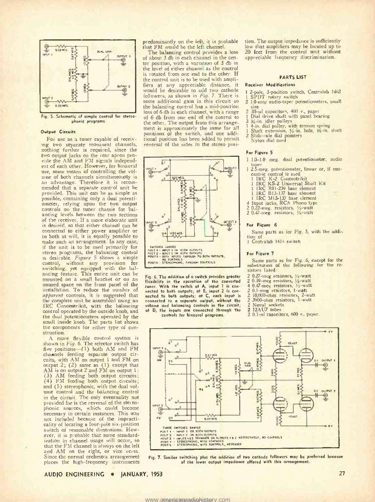
C
NPUT 1
INPUT 2
C
0 22 MEG
o
022MEG
DUAL GAIN
OUTPUT 1
o
DuTPUT 2
Fig. 5. Schematic of simple control for stereo- phonic programs.
Output Circuits
For use as a tuner capable of receiv- ing two separate monaural channels, nothing further is required, since the two output jacks on the rear apron pro- vide the AM and FM signals independ- ent of each other. However, for binaural use. some means of controlling the vol- ume of both channels simultaneously is an advantage. Therefore it is recom- mended that a separate control unit be provided. This unit can be as simple as possible, containing only a dual potenti- ometer, relying upon the two output controls on the tuner chassis for bal- ancing levels between the two sections of the receiver. If a more elaborate unit is desiréd, so that either channel can be connected to either power amplifier or to both at will, it is equally possible to make such an arrangement. In any case, if the unit is to be used primarily for stereo programs, the balancing control is desirable. Figure 5 shows a simple control, without any provision for switching, yet equipped with the bal- ancing feature. This entire unit can be mounted on a small bracket or on an unused. space on the front panel of the installation. To reduce the number of apparent controls, it is suggested that the complete unit be assembled using an IRC Concentrikit, with the balancing control operated by the outside knob, and the dual potentiometers operated by the small inside knob. The parts list shows the components for either type of con- struction.
A more flexible control system is shown in Fig. 6. The selector switch has five positions -(1) both AM and FM channels feeding separate output cir- cuits, with AM on output 1 and FM on output 2; (2) same as (1) except that AM is on output 2 and FM on output 1; (3) AM feeding both output circuits; (4) FM feeding both output circuits; and (5) stereophonic, with the dual vol- ume control and the balancing control in the circuit. The only eventuality not provided for is the reversal of the stereo- phonic sources, which could become necessary in certain instances. This was not included because of the impracti- cality of locating a four -pole six -position switch of reasonable dimensions. How- ever, it is probable that some standard- ization in channel usage will occur, so that the FM channel is always on the left and AM on the right, or vice versa. Since the normal orchestra arrangement places the high -frequency instruments
predominantly on the left, it is probable that FM would be the left channel.
The balancing control provides a loss of about 3 db in each channel in the cen- ter position, with a variation of 3 db in the level of either channel as the control is rotated from one end to the other. If the control unit is to be used with ampli- fiers at any appreciable distance, it would be desirable to add two cathode followers, as shown in Fig. 7. There is some additional gain in this circuit so the balancing control has a mid- position loss of 6 db in each channel, with a range of 6 db from one end of the control to the other. The output from this arrange- ment is approximately the same for all positions of the switch, and one addi- tional position has been added to permit reversal of the sides in the stereo posi-
TI
3
UT 2
C
A 022ME
2
s
Ti
OIT' T 2
SWITCHES GANGED POSIT 1 - INPUT 1 ON BOTH OUTPUTS POSIT 2 - INPUT 2 ON BOTH OUTPUTS POSITS BOTH INPUTS THROUGH TO BOTH OUTPUTS,
NO CONTROLS POSIT A STEREOPHONIC, THROUGH CONTROLS
Fig. 6. The addition of a switch provides greater flexibility in the operation of the converted tuner. With the switch at A, input 1 is con- nected to both outputs; at E, input 2 is con- nected to both outputs; at C, each input is
connected to o separate ourput, without the volume and balancing controls in the circuit; at D, the inputs are conne:ted through the
controls for binaural programs.
tion. The output impedance is sufficiently low that amplifiers may be located up to 20 feet from the control unit without appreciable frequency discrimination.
PARTS LIST
Receiver Modifications
1 2 -pole, 3- position switch, Centralab 1462 1 SPDT rotary switch 2 1.0 -meg audio-taper potentiometers, small
size 2 .05 -µf capacitors, 400 v., paper 1 Dial drive shaft with panel bearing 3 x -in. idler pulleys 1 4 -in. dial pulley, with tension spring 1 Shaft extension, 54-in. hole, } -in. shaft 2 Slide -rule dial pointers
Nylon dial cord
For Figure 5
1 1.0 -1.0 meg. dual potentiometer, audio taper
1 2.5 -meg. potentiometer, linear or, if con- centric control is used 1 IRC K -2 Concentrikit 1 IRC KS -2 Universal Shaft Kit 1 IRC B11 -239 base element 1 IRC B13 -137 base element 1 IRC M13 -137 base element
4 Input jacks, RCA Phono type 2 0.22 -meg. resistors, 4-watt 2 0.47 -meg. resistors, Y2-watt
For Figure 6
Same parts as for Fig. 5, with the addi- tion of 1 Centralab 1414 switch
For Figure 7
Sanie parts as for Fig. 6, except for the substitution of the following for the re- sistors listed: 2 027 -meg resistors, % -watt 2 0.39 -meg resistors, Ys-watt 4 0.47 -meg resistors, % -watt 2 0.1 -meg resistors, 1 -watt 2 10,000 -ohm resistors, 2 -watt 2 3900 -ohm resistors, 1 -watt 2 Nova! sockets 2 12AU7 tubes 2 0.1 -µf capacitors, 600 v., paper.
D D2
INPUT 1
C
AM
3
,PUT 2
L- 32
OS
01 2
C ` 3
11111 M
o
AO3á a
TA n
vw ( 21 MEG
DUAL GAIN
a
12AU7
01 OUTPUT I
U1 OUTPUT 2
2 AUT
THREE SWITCHES GANGED
POSIT 1 - INPUT 1 ON BOTH OUTPUTS
POSIT 2 INPUT 2 ON BOTH OUTPUTS
POSIT 3 INPUTS I B 2 5E ON OUTPUTS AG 2 RESPECTIVELY, NO CONTROLS
POSIT STEREOPHONIC, WITH CONTROLS
POSIT 5 STEREOPHONIC, WITH CONTROLS, REVERSED
Fig. 7. Similar switching plus the addition of two cathode followers may be preferred because of the lower output impedance offered with this arrangement.
AUDIO ENGINEERING JANUARY, 1953 27
www.americanradiohistory.comAmericanRadioHistory.Com
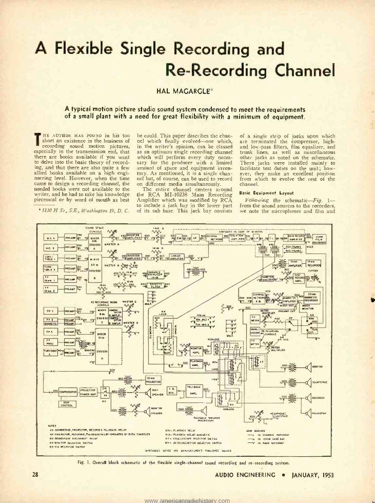
A Flexible Single Recording and Re- Recording Channel
HAL MAGARGLE
A typical motion picture studio sound system condensed to meet the requirements of a small plant with a need for great flexibility with a minimum of equipment.
THE AUTHOR HAS FOUND in his too short an existence in the business of recording sound motion pictures,
especially in the transmission end, that there are books available if you want to delve into the basic theory of record- ing, and that there are also quite a few allied books available on a high engi- neering level. However, when the time came to design a recording channel, the needed books were not available to the writer, and he had to take his knowledge piecemeal or by word of mouth as best
5130 H St., S.E., Washington 19, D. C.
he could. This paper describes the chan- nel which finally evolved -one which, in the writer's opinion, can be classed as an optimum single recording channel which will perform every duty neces- sary for the producer with a limited amount of space and equipment inven- tory. As mentioned, it is a single chan- nel but, of course, can be used to record on different media simultaneously.
The entire channel centers around the RCA MI -10238 Main Recording Amplifier which was modified by RCA to include a jack bay in the lower part of its sub base. This jack bay consists
of a single strip of jacks upon which are terminated the compressor, high - and low -pass filters, film equalizer, and trunk lines, as well as miscellaneous other jacks as noted on the schematic. There jacks were installed mainly to facilitate test duties on the unit; how- ever, they make an excellent position from which to evolve the rest of the channel.
Basic Equipment Layout
Following the schematic -Fig. 1- from the sound sources to the recorders, we note the microphones and film and
EMI !El MID t
TURN - TABLE N
TURN TABLE t
MEABP
MEO
MANN
Bo
SOUND STAGE
CONSOLE
Mr
eso
AMEN G tavtw
A
Iw -;
W
MEAr
AMM 200 V
MIXER
SA db
eBOEtso
IS
S0031EN AMPLIE ER
250 S GOO
R[IECOROBNI ROOM MASTER C
COMBOS Mn8
500
SOO
MASTER D
ML
B
MOM 600 S00
sdb
600
SOD
MABNETK AMPLna
MIXER OUT
J
METER
METER
ME ER T R
400
SCAMP OUT
SS r MAGNETIC RECORDER
HOER MONITOR
KB NT r WC 1
BMEI
NE RE000S CONSOLE
MOTES
KN- BOUOSTADE, PROJECTOR, RECORDER TALKBACH RELAY
Kt -PROJECTOR, RECORDER, RELAY OPERATED RV BOTH CONSOLE»
K)- »OIMDSTAGE DISCONNECT RELAY
-MONITOR SELECTOR SWITCH KS -VU SELECTOR SWITCH
S
ID
TALK SAC 500
MPL
II
K2
GOO
METER MLTALIEN
J
I II° .f IMOxrtm
1"II` sawnST.-.i
1111
TLKBACK SPEAKER PROJECTORS
K6. -PL AT BACK RELAY
K66 - PLAYBACK RELAY -MAGNETIC
K - OSCILLOSCOPE SELECTOR SWITCH
K 6 - I6 -35 PROJECTOR SELECTOR SWITCH
OCK
IMPEDANCES NOTED ARE MAMJEACTURER'S PUBLISHED VALUES
V R SOUNDSTAGE
JACK MARKING
-v IN CONSOLE PATOISÂT
102 SS CASE BAY
-K. IN RACK PATCHBAY
CORDER
CTOP
28
Fig. 1. Overall block schematic of the flexible single -channel sound recording and re- recording system.
AUDIO ENGINEERING JANUARY, 1953
www.americanradiohistory.comAmericanRadioHistory.Com
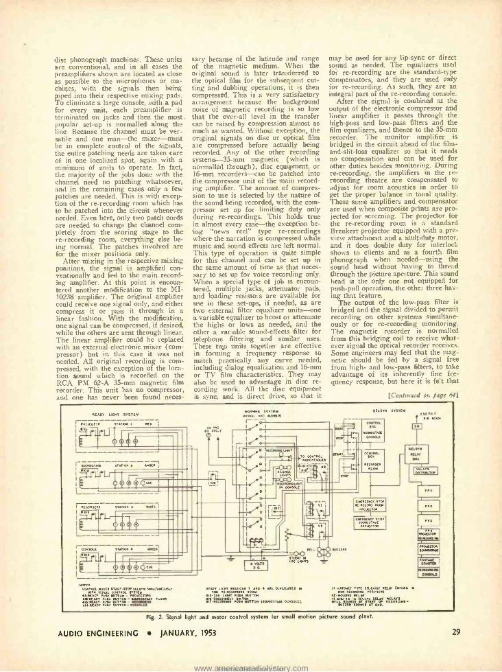
disc phonograph machines. These units are conventional, and in all cases the preamplifiers shown are located as close as possible to the microphones or ma- chines, with the signals then being piped into their respective mixing pads. To eliminate a large console, with a pad for every unit, each preamplifier is terminated on jacks and then the most. popular set -up is normalled along the line. Because the channel must be ver- satile and one man -the mixer -must be in complete control of the signals, the entire patching needs are taken care of in one localized spot, again with a minimum of units to operate. In fact, the majority of the jobs done with the channel need no patching whatsoever, and in the remaining cases only a few patches are needed. This is with excep- tion of the re- recording room which has to be patched into the circuit whenever needed. Even here, only two patch cords are needed to change the channel com- pletely from the scoring stage to the re- recording room, everything else be- ing normal. The patches involved are for the mixer positions only.
After mixing in the respective mixing positions, the signal is amplified con - ventionally and fed to the main record- ing amplifier. At this point is encoun- tered another modification to the MI- 10238 amplifier. The original amplifier could receive one signal only, and either compress it or pass it through in a linear fashion. With the modification, one signal can be compressed, if desired, while the others are sent through linear. The linear amplifier could be replaced with an external electronic mixer (com- pressor) but in this case it was not needed. All original recording is com- pressed, with the exception of the loca- tion sound which is recorded on the RCA PM 62 -A 35 -mm magnetic film recorder. This unit has no compressor, and one has never been found neces-
sary because of the latitude and range of the magnetic medium. When the original sound is later transferred to the optical film for the subsequent cut- ting and dubbing operations, it is then compressed. This is a very satisfactory arrangement because the background noise of magnetic recording is so low that the over -all level in the transfer can be raised by compression almost as much as wanted. Without exception, the original signals on disc or optical film are compressed before actually being recorded. Any of the other recording systems -35 -mm magnetic (which is normalled through), disc equipment, or 16 -mm recorders -can be patched into the compressor unit of the main record- ing amplifier. The amount of compres- sion to use is selected by the nature of the sound being recorded, with the com- pressor set up for limiting duty only during re- recordings. This holds true in almost every case -the exception be- ing "news reel" type re- recordings where the narration is compressed while music and sound effects are left normal. This type of operation is quite simple for this channel and can be set up in the same amount of time as that neces- sary to set up for voice recording only. When a special type of job is encoun- tered, multiple jacks, attenuator pads, and loading resistors are available for use in these set -ups, if needed, as are two external filter equalizer units -one a variable equalizer to boost or attenuate the highs or lows as needed, and the other a variable sound -effects filter for telephone filtering and similar uses. These two units together are effective in forming a frequency response to match practically any curve needed, including dialog equalization and 16 -mm or TV film characteristics. They may also be used to advantage in disc re- cording work. All the disc equipment is sync, and is direct drive, so that it
may be used for any lip -sync or direct sound as needed. The equalizers used for re- recording are the standard -type compensators, and they are used Only for re- recording. As such, they are an integral part of the re- recording console.
After the signal is combined at the output of the electronic compressor and linear amplifier it passes through the high -pass and low -pass filters and the film equalizers, and thence to the 35 -mm recorder. The monitor amplifier is bridged in the circuit ahead of the film - and- slit -loss equalizer so that it needs no compensation and can be used for other duties besides monitoring. During re- recording, the amplifiers in the re- recording theatre are compensated to adjust for room acoustics in order to get the proper balance in tonal quality. These same amplifiers and compensator are used when composite prints are pro- jected for screening. The projector for the re- recording room is a standard Brenkert projector equipped with a pre- view attachment and a multiduty motor, and it does double duty for interlock shows to clients and as a fourth film phonograph when needed -using the sound head without having to thread through the picture aperture. This sound head is the only one not equipped for push -pull operation, the other three hav- ing that feature.
The output of the low -pass filter is bridged and the signal divided to permit recording on other systems simultane- ously or for re- recording monitoring. The magnetic recorder is normalled from this bridging coil to receive what- ever signal the optical recorder receives. Some engineers may feel that the mag- netic should be fed by a signal free from high - and low -pass filters, to take advantage of its inherently fine fre- quency response, but here it is felt that
[Continued on page 64]
READY LIGHT SYSTEM
ÇPUO EOHO STATION E R[0 ¡
1
I SOINDSTNE ETATION [ AIM
I 00
i It
OJE
------------ STATION 3 ANTE I
o
CONSOLE
".1'irl STATION I SIIfOI
NOTES
CONTROL RODEI ETARTSTOP SELVES SMLLTANEOUSLY TH MM. CONTROL ST
All PUMP SUTTON - PROJECTORS 102 -READY PRIMI SUTTON - SOINOSTAGE FLOOR M. ROOT PINS MNTTON - RECORDERS NI READY PUSH SUTTON - CONSOLES
WARMS SYSTEM ry1211M. MM WDMLO I- ,1
NS MC IV. 110 CU. ,
I o o-F-
TO CONTROL ' RECEPTACLES
iE LEÑ
NWOMSMLIOT ON CONSOLE
MT
DIM
S VOLTS GEC.
STUOO M VSE LINTS
READY LKNT STATIONS I AND ARE DUPLICATED IN TNT R NECOROWN ROOM
CUE LIGHT PUSH DUTTON RN D SGOMECTSWIT
NIT RECORDING PUSH SUTTON (SOON[ STAGE CONSOLE)
N1
SELSYN SYSTEM
CONTROL SOS
SOAMSTAM COMM
D OE
RECORDER
N OON
EINRGEROTlTO' RE-RECO M 00M
PROJECTOR
ONUEENCY STOP SOMMSTACE
PROJECTOR
250vaT . EOar1
SELINA
RELAY
DOE
EELSY DersuraR
S1 IGNET TYPE SaENOO SELO (SHORN IN
HOLDING REGORONO POSITION,
52 NO
ONO RELAY VI SECOND DELAY RELATS BELL SOOIO! START Of NECOR PING -
RO2ICR SOUNDS AT END.
PPS
FP1 PROJECTOR
RRCpMIRI
PROJECTOR
EOUS»MSE
MINK COUNTER
RINTCOMRN CONSOLE
Fig. 2. Signal light and motor control system or small motion picture sound plant.
AUDIO ENGINEERING JANUARY, 1953 29
www.americanradiohistory.comAmericanRadioHistory.Com
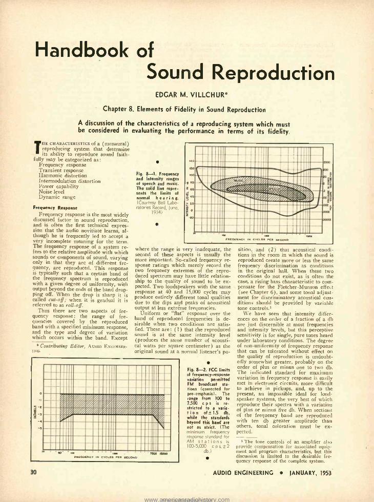
Handbook of Sound Reproduction
EDGAR M. VILLCHUR'
Chapter 8. Elements of Fidelity in Sound Reproduction
A discussion of the characteristics of a reproducing system which must be considered in evaluating the performance in terms of its fidelity.
THE CHARACTERISTICS of a (monaural) reproducing system that determine its ability to reproduce sound faith-
fully may be categorized as: Frequency response Transient response Harmonic distortion Intermodulation distortion Power capability Noise level Dynamic range
Frequency Response
Frequency response is the most widely discussed factor in sound reproduction, and is often the first technical expres- sion that the audio novitiate learns, al- though he is frequently led to accept a very incomplete meaning for the term. The frequency response of a system re- fers to the relative amplitude with which sounds or components of sound, varying only in that they are of different fre- quency, are reproduced. This response is typically such that a certain band of the frequency spectrum is reproduced with a given degree of uniformity, with output beyond the ends of the band drop- ping off. When the drop is sharp it is called cut -off; when it is gradual it is referred to as roll-off.
Thus there are two aspects of fre- quency response: the range of fre- quencies covered by the reproduced band with a specified minimum response, and the type and degree of variation which occurs within the band. Except
* Contributing Editor, AUDIO ENGINEER- ING.
Fig. 8 -1. Frequency and intensity ranges of speech and music. The solid line repre- sents the limits of normal hearing. (Courtesy Bell L,1 ratories Record,
r
LI _,
1934)
.Q
= 6a
`°
z o
E,
:111111 r! AMINE Et fr. ..r
III °
.1111 -_- - IMI
!ls...::%: /i ,.}-.:;:; /,¡ii .....'.':.i::s:..//F,,1
ilüiiíïr;;
,.. MINI IP s s ''' ïii;:: ' ::-:: ;,,
=;1 \ III ' Illillll\IIIII 1111 1 -'E9 U
`r
11111 1111111 1 III
p . law FREQUENCY IN CYCLES PER SECOND
moo
where the range is very inadequate, the second of these aspects is usually the more important. So- called frequency re- sponse ratings which merely record the two frequency extremes of the repro- duced spectrum may have little relation- ship to the quality of sound to be ex- pected. Two loudspeakers with the same response at 40 and 15,000 cycles may produce entirely different tonal qualities due to the dips and peaks of acoustical output at less extreme frequencies.
Uniform or "flat" response over the band of reproduced frequencies is de- sirable when two conditions are satis- fied. These are : (1) that the reproduced sound is at the same intensity level (produces the same number of acousti- cal watts per square centimeter) as the original sound at a normal listener's po-
9
rïi4 i i "iiii i i :i %/e' %%%Ìiij %%''i %j4ii/ %4//,.iii%4ikii %i%i :iii % //I/r
r-
'o ' 90 IY IM - 7900 0000 FREQUENCY IN CYCLES PER SECOND
30
Fig. 8-2. FCC limits Df frequency - response variation permitted FM broadcast sta- tions corrected for pre -emphasis). The range from 100 to 7.500 c p s is re- stricted to a varia- tion of 1.5 db, while the standards beyond this band are not as strict. (The minimum frequency response standard for AM stations is 100 -5,000 cps, ±2
db.)
sition, and (2) that acoustical conch tions in the room in which the sound is reproduced create more or less the same frequency discrimination as conditions in the original hall. When these two conditions do not exist, as is often the case, a rising bass characteristic to com- pensate for the Fletcher- Munson effect (see Chapter 6), and some tonal adjust- ment for discriminatory acoustical con- ditions should be provided by variable tone controls.'
We have seen that intensity differ- ences on the order of a fraction of a db are just discernible at most frequencies and intensity levels, but this perceptive sensitivity is for single, pure tones heard under laboratory conditions. The degree of non -uniformity of frequency response that can be tolerated without effect on the quality of reproduction is undoubt- edly somewhat greater, probably on the order of plus or minus one to two db. The indicated standard for maximum variation in frequency response is easily met in electronic circuits, more difficult to achieve in pickups, and, up to the present, an impossible ideal for loud- speaker systems, the very best of which reproduce their spectra with a variation of plus or minus five db. When sections of the frequency band are reproduced with ten db greater amplitude than others, tonal coloration must be ex- pected.
' The tone controls ui an amplifier also provide compensation for associated equip- ment and program characteristics, but this discussion is limited to the desirable fre- quency response of the complete system.
AUDIO ENGINEERING IANUARY, 1953
www.americanradiohistory.comAmericanRadioHistory.Com
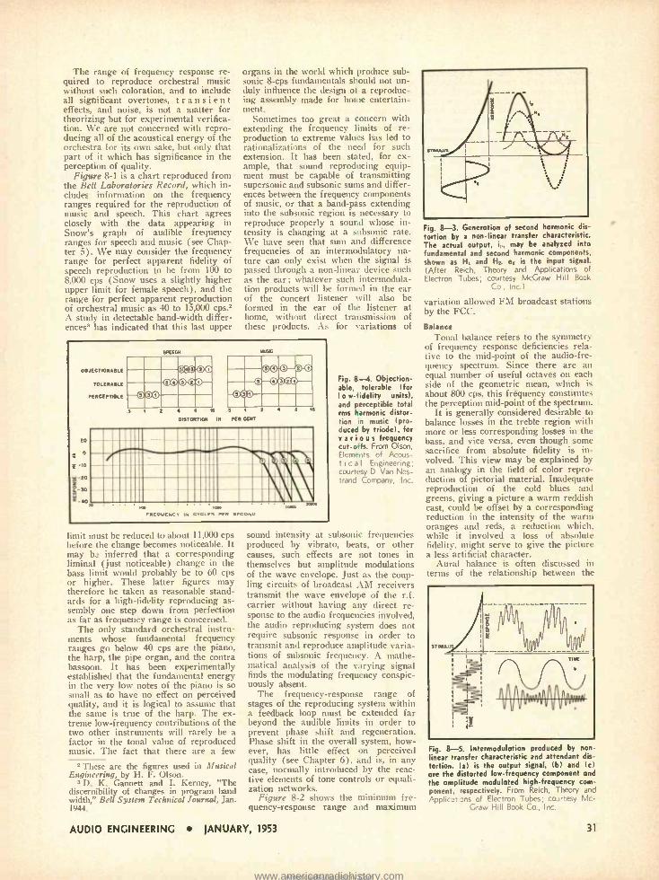
The range of frequency response re- quired to reproduce orchestral music without such coloration, and to include all significant overtones, transient effects, and noise, is not a matter for theorizing but for experimental verifica- tion. We are not concerned with repro- ducing all of the acoustical energy of the orchestra for its own sake, but only that part of it which has significance in the perception of quality.
Figure 8 -1 is a chart reproduced from the Bell Laboratories Record, which in- cludes information on the frequency ranges required for the reproduction of music and speech. This chart agrees closely with the data appearing in Snow's graph of audible frequency ranges for speech and music (see Chap- ter 5). We may consider the frequency range for perfect apparent fidelity of speech reproduction to be from 100 to 8,000 cps (Snow uses a slightly higher upper limit for female speech), and the range for perfect apparent reproduction of orchestral music as 40 to 15,000 cps .2
A study in detectable band -width differ- ences3 has indicated that this last upper
organs in the world which produce sub- sonic 8 -cps fundamentals should not un- duly influence the design of a reproduc- ing assembly made for home entertain- ment.
Sometimes too great a concern with extending the frequency limits of re- production to extreme values has led to rationalizations of the need for such extension. It has been stated, for ex- ample, that sound reproducing equip- ment must be capable of transmitting supersonic and subsonic sums and differ- ences between the frequency components of music, or that a band -pass extending into the subsonic region is necessary to reproduce properly a sound whose in- tensity is changing at a subsonic rate. We have seen that sum and difference frequencies of an intermodulatory na- ture can only exist when the signal is passed through a non-linear device such as the ear; whatever such intermodula- tion products will be formed in the ear of the concert listener will also be formed in the ear of the listener at home, without direct transmission of these prodects. As for variations of
CBJECTICNASLE
TOLERABLE
rENCEVTMILE
20
o
: IO
20
h-30
SPEECH
ET r Wi lIW iW WIC mown"
mPw4*ior Ymummi
.s r 2 4 s x .
OtSYOSTIO r IN KN CENT
__..70e=ttnr
-4o
FREOIIENCY IN CYCLES PER SECOND
limit must be reduced to about 11,000 cps before the change becomes noticeable. It may b. inferred that a corresponding liminal (just noticeable) change in the bass limit would probably be to 60 cps or higher. These latter figures may therefore be taken as reasonable stand- ards for a high -fidelity reproducing as- sembly one step down from perfection as far as frequency range is concerned.
The only standard orchestral instru- ments whose fundamental frequency ranges go below 40 cps are the piano, the harp, the pipe organ, and the contra bassoon. It has been experimentally established that the fundamental energy in the very low notes of the piano is so small as to have no effect on perceived quality, and it is logical to assume that the same is true of the harp. The ex- treme low- frequency contributions of the two other instruments will rarely be a factor in the tonal value of reproduced music. The fact that there are a few
2 These are the figures used in Musical Engineering, by H. F. Olson.
3 D. K. Gannett and I. Kerney, "The discernibility of changes in program band width," Bell System Technical Journal, Jan. 1944.
Fig. 8--4. Objection- able, tolerable (for I o w- fidelity units), and perceptible total rms harmonic distor- tion in music (pro- duced by triode), for various frequency cut -offs. From Olson, Elements of Acous- t i c a l Engineering; courtesy D. Van Nos - trand Company, Inc.
sound intensity at subsonic frequencies produced by vibrato, beats, or other causes, such effects are not tones in themselves but amplitude modulations of the wave envelope. Just as the coup- ling circuits of broadcast AM receivers transmit the wave envelope of the r.f. carrier without having any direct re- sponse to the audio frequencies involved, the audio reproducing system does not require subsonic response in order to transmit and reproduce amplitude varia- tions of subsonic frequency. A mathe- matical analysis of the varying signal finds the modulating frequency conspic- uously absent.
The frequency -response range of stages of the reproducing system within a feedback loop must be extended far beyond the audible limits in order to prevent phase shift and regeneration. Phase shift in the overall system, how- ever, has little effect on perceived quality (see Chapter 6), and is, in any case, normally introduced by the reac- tive elements of tone controls or equali- zation networks.
Figure 8 -2 shows the minimum fre- quency- response range and maximum
AUDIO ENGINEERING JANUARY, 1953
Fig. 8-3. Generation of second harmonic dis- tortion by a non- linear transfer characteristic. The actual output, i,., may be analyzed into fundamental and second harmonic components, shown as It and H. el is the input signal. (After Reich, Theory and Applications of
Electron Tubes; courtesy McGraw Hill Book Co., Inc.)
variation allowed FM broadcast stations by the FCC.
Balance Tonal balance refers to the symmetry
of frequency response deficiencies rela- tive to the mid -point of the audio -fre- quency spectrum. Since there are an equal number of useful octaves on each side of the geometric mean, which is about 800 cps, this frequency constitutes the perception mid -point of the spectrum.
It is generally considered desirable to balance losses in the treble region with more or less corresponding losses in the bass, and vice versa, even though some sacrifice from absolute fidelity is in- volved. This view may be explained by an analogy in the field of color repro- duction of pictorial material. Inadequate reproduction of the cold blues and greens, giving a picture a warm reddish cast, could be offset by a corresponding reduction in the intensity of the warm oranges and reds, a reduction which, while it involved a loss of absolute fidelity, might serve to give the picture a less artificial character.
Aural balance is often discussed in terms of the relationship between the
Fig. 8-5. Intermodulation produced by non- linear transfer characteristic and attendant dis- tortion. (a) is the output signal, (b) and (c) are the distorted low- frequency component and the amplitude modulated high- frequency com- ponent, respectively. From Reich, Theory and Applications of Electron Tubes; courtesy Mc-
Graw Hill Book Co., Inc.
31
www.americanradiohistory.comAmericanRadioHistory.Com
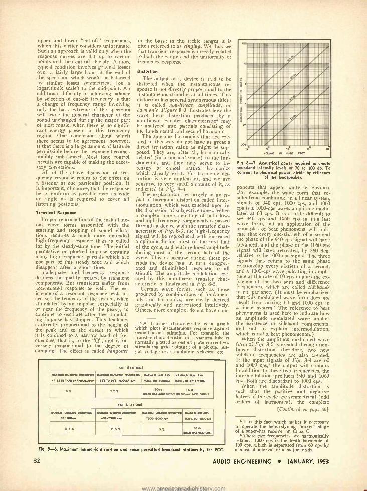
man. . a l 111
II .0811 1. .8111 I rarJ. 5 I I I I mmgumlmmalIrwin' morn ni
, IIIIllll11 III.ÌI1111111111111.
11111
ï Ciiiiii%a i 'iti'=ii' =111111111/4111 1111 /III I MIMI III
MN Ill
_=_' ===5:::===e:
i
msíiiiiiiiiï ill=i.íiiiMii.íiil I/mIl III111R 1 II /UIII IINIPA 1111
,111IIIIR;%II 1111M1111111131111111
II111111111111 /111111IIIIII 111111!%111111101111111111111111111
upper and lower "cut -off" frequencies, which this writer considers unfortunate. Such an approach is valid only when the response curves are flat up to certain points and then cut off sharply. A more typical condition involves gradual losses over a fairly large band at the end of the spectrum, which would be balanced by similar losses symmetrical (on a logarithmic scale) to the mid -point. An additional difficulty in achieving balance by selection of cut-off frequency is that a change of frequency range involving only the bass extreme of the spectrum will leave the general character of the sound unchanged during the major part of most music, when there is no signifi- cant energy present in this frequency region. One conclusion about which there seems to be agreement, however, is that there is a large amount of latitude permissible before the response becomes audibly unbalanced. Most tone control circuits are capable of making the neces- sary corrections.
All of the above discussion of fre- quency response refers to the effect on a listener at one particular position. It is important, of course, that the response be as uniform as possible over as wide an angle as is required to cover all listening positions.
Transient Response
Proper reproduction of the instantane- ous wave forms associated with the starting and stopping of sound vibra- tions requires a much more extended high -frequency response than is called for by the steady -state tone. The initial percussive or plucked impulse contains many high -frequency partials which are not part of this steady tone and which disappear after a short time.
Inadequate high- frequency response deadens the quality created by transient components. But transients suffer from accentuated response as well. The ex- istence of a resonant response peak in- creases the tendency of the system, when stimulated by an impulse (especially at or near the frequency of the peak), to continue to oscillate after th'e stimulat- ing impulse has stopped. This tendency is directly proportional to the height of the peak and to the extent to which it is confined to a narrow band of fre- quencies, that is, to the "Q ", and is in- versely proportional to the degree of damping. The effect is called hangover
in the bass; in the treble ranges it is often referred to as singing. We thus see that transient response is directly related to both the range and the uniformity of frequency response.
Distortion
The output of a device is said to be distorted when the instantaneous re- sponse is not directly proportional to the instantaneous stimulus at all times. This distortion has several synonymous titles :
it is called non -linear, amplitude, or harmonic. Figure 8 -3 illustrates how the wave form distortion produced by a non -linear transfer characteristic* may be analyzed into partials consisting of the fundamental and second harmonic.
The spurious harmonics that are cre- ated in this way do not have as great a direct irritation value as might be sup- posed. They are, after all, harmonically related (in a musical sense) to the fun- damental, and they may serve to in- tensify or cancel natural harmonics which already exist. Yet harmonic dis- tortion is very unpleasant, and we are sensitive to very small amounts of it, as indicated in Fig. 8 -4.
The explanation lies largely in an ef- fect of harmonic distortion called inter - modulation, which was touched upon in the discussion of subjective tones. When a complex tone consisting of both low - and high -frequency components is passed through a device with the transfer char- acteristic of Fig. 8-3, the high- frequency signal will be reproduced with increased amplitude during most of the first half of the cycle, and with reduced amplitude during most of the second half of the cycle. This is because during these pe- riods the device has, in turn, exagger- ated and diminished response to all stimuli. The amplitude modulation cre- ated by this non -linear transfer char- acteristic is illustrated in Fig. 8 -5.
Certain wave forms, such as those produced by combinations of fundamen- tals and harmonics, are easily derived graphically and understood intuitively. Others, more complex, do not have com-
4 A transfer characteristic is a graph which plots instantaneous response against instantaneous stimulus. For example, the transfer characteristic of a vacuum tube is normally plotted as output plate current vs. stimulating grid voltage; of a pickup, out- put voltage vs. stimulating velocity, etc.
AM STATIONS
MAXIMUM NMNp11G DISTORTION
AT LESS THAN 94%81008.ATION
MAXIMUM NARMOMG DISTORTION
85% TO 93% MODULATION
MAXIMUM NUM AND
NOSE,I50 -5000cRe
MAXIMUM NUN AND
NOSE, OTTER FREDS.
5% 7.5% 5011 BELOW MAX AM. OUTPUT
4011 BELOW MAX AUDIO OUTPUT
FM STATIONS
MAXIMUM NARMDMG DISTORTION
SO' 100c11
MAXMIM NMMONG DISTORTION
100 -7500 <1c
MAXIMUM NAIBIDMG DISTORTION
1500 -15000 <1<
MAXANM NUM AND
NOSE. 50'15000 cos
3 5% 2 5% 3% 6011
BELOW MAX ALGA our
Fig. 8-6. Maximum harmonic distortion
32
and noise permitted broadcast stations by the FCC.
.o
001
lo 1O q* VOLUME N DUBIO FEET
_.:I1;== r.::I111=M:::iiii=a:: C7111 ÌiÍ1111111L rllll.11111.NIIIII I/i 11111I 1E i 11111I 11MUIIIII=1111II IIIIII;FAIIIIIIII.IIIIIII11IIIII111
BOT
Fig. 8-7. Acoustical power required to create soundand intensity levels of 70 to 100 db. To convent to electrical power, divide by efficency
of the loudspeaker.
ponents that appear quite as obvious. For example, the wave form that re- sults from combining, in a linear system, signals of 940 cps, 1000 cps, and 1060 cps is a 1000 -cps wave, amplitude modu- lated at 60 cps. It is a little difficult to see 940 cps and 1060 cps in this last wave form, but an application of the principles of beat phenomena will indi- cate that every one -sixtieth of a second the phase of the 940 -cps signal will have advanced, and the phase of the 1060 -cps signal will have retreated, by 360 deg. relative to the 1000 -cps signal. The three signals thus return to the same phase relationship every sixtieth of a second. and a 1000 -cps wave pulsating in ampli- tude at the rate of 60 cps implies the ex- istence of the two sum and difference frequencies, which are called sidebands in r.f. parlance. (It must be emphasized that this modulated wave form does not result from mixing 60 and 1000 cps in a linear system.5 The reference to beat phenomena is used here to indicate how an amplitude modulated wave implies the existence of sideband components, and not to explain intermodulation, which is not a beat phenomenon.)
When the amplitude modulated wave form of Fig. 8 -5 is created through non- linear distortion, therefore, two new sideband frequencies are also created. If the input signals of Fig. 8-4 are 60 and 1000 cps,B the output will contain, in addition to these two frequencies, the intermodulation products 940 and 1060 cps. Both are discordant to 1000 cps.
When the amplitude distortion is such that the positive and negative halves of the cycle are symmetrical (odd orders of harmonics), the complete
[Continued on page 60j
It is this fact which makes it necessary to operate the heterodyning "mixer" stage of a super -het receiver in Class C.
6 These two frequencies are harmonically related; 1000 cps is the tenth harmonic of 100 cps, which is separated from 60 cps by a musical interval of a major sixth.
AUDIO ENGINEERING JANUARY, 1953
www.americanradiohistory.comAmericanRadioHistory.Com
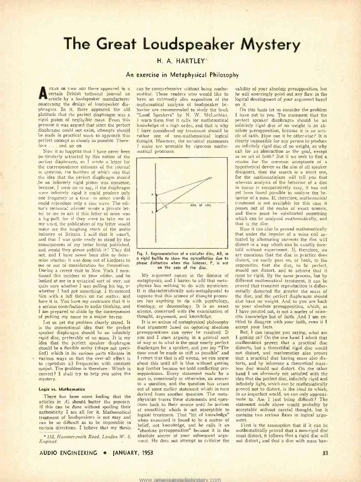
The Great Loudspeaker Mystery H. A. HARTI.EY
An exercise in Metaphysical Philosophy
AYEAR OR TWO AGO there appeared in a certain British technical journal an article by a loudspeaker manufacturer
concerning the design of loudspeaker dia- phragms. In it, there appeared the old platitude that the perfect diaphragm was a rigid piston of negligible mass. From this premise it was argued that since the perfect diaphragm could not exist, attempts should be made in practical work to approach this perfect concept as closely as possible. There- fore ... and so on.
Now it so happens that I have never been particularly attracted by this notion of the perfect diaphragm, so I wrote a letter for the correspondence columns of the journal in question, the burthen of which was that the idea that the perfect diaphragm should be an infinitely rigid piston was nonsense. because. I went on to say, if the diaphragm were infinitely rigid it could produce n
one frequency at a time -in other word. n
could reproduce only a sine wave. The edi- tor's technical adviser wrote a private let- ter to me to ask if this letter of mine wa, a leg -pull. for if they were to take me at my word, the publication of my letter would make me the laughing stock of the audio industry of Britain. I said that it wasn't, and that I was quite ready to stand by the consequences of my letter being published. and would they please publish it? They did not, and I have never been able to deter- mine whether it was done out of kindness to me or out of consideration for themselves. During a recent visit to New York I men- tioned this incident to your editor, and he looked at me in a quizzical sort of way, not quite sure whether I was pulling his leg, or whether I had got something. I threatened him with a full thesis on the matter, and here it is. You have my assurance that it is a serious contribution to audio thinking, and I am prepared to abide by the consequences of putting my name to a major heresy.
Let us get the problem clearly stated. It is the conventional idea that the perfect speaker diaphragm should be an infinitely rigid disc, preferably of no mass. It is my idea that the perfect speaker diaphragm should be a flexible entity (shape not speci- fied) which in its various parts vibrates in various ways so that the over -all effect is to reproduce all frequencies with constant output. The problem is therefore: Which is correct? I shall try to help you solve the mystery.
Logic vs. Mathematics
There has been some feeling that the articles in Æ should butter the popcorn. If this can be done without spoiling their authenticity I am all for it. Mathematical treatment of loudspeakers is not easy and can be so difficult as to be impossible in certain directions. I believe that my thesis
* 152, Hammersmith Road, London W. 6, England.
can be comprehensive without being mathe- matical. Those readers who would like to have an extremely able exposition of the mathematical analysis of loudspeaker be- havior are recommended to study the book "Loud Speakers" by N. W. McLachlan. I warn them that it calls for mathematical knowledge of a high order, and that is why I have considered my treatment should be rather one of non -mathematical logical thought. However, the technical statements I make are provable by rigorous mathe- matical processes.
axis CF DISC
Fig. 1. Representation of a circular disc, AB, in a rigid baffle to show the cancellation due to phase distortion when the listener, P, is not
on the axis of the disc.
My argument comes in the domain of metaphysics, and I hasten to add that meta- physics has nothing to do with mysticism. It is characteristically anti -metaphysical to suppose that this science of thought proces- ses has anything to do with psychology, theology, or demonology. It is an exact science, concerned with the examination of thought, argument, and knowledge.
It is an axiom of metaphysical philosophy that argument based on opposing absolute presuppositions can never be resolved. If you and I start arguing ir. a general sort of way as to what is the most nearly perfect diaphragm for a speaker, and you say "The cone must be made as stiff as possible" and I retort that that is all wrong, we can argue about this until all is blue without getting any further because we hold conflicting pre- suppositions. Every statement made by a man is, consciously or otherwise, an answer to a question, and the question has arisen out of some earlier statement which in turn derived from another question. The meta- physician traces these statements and ques- tions back to their source until he arrives at something which is not susceptible to logical treatment. That "bit of knowledge" when examined is found to be a matter of belief, not knowledge, and he calls it an "absolute presupposition" because it is the absolute source of your subsequent argu- ment. He does not attempt to criticise the
validity of your absolute presupposition, but he will unerringly point out any flaw in the logical development of your argument based on it.
On this basis let us consider the problem I have put to you. The statement that the perfect speaker diaphragm should be an infinitely rigid disc of no weight is an ab- solute presupposition, because it is an arti- cle of faith. How can it be otherwise? It is clearly impossible for any person to produce an infinitely rigid disc of no weight, so why call for an abstraction as the goal, except as an act of faith ? But if we seek to find a reason for the common acceptance of a hypothetical device as the aim of all speaker designers, then the search is a short one, for the mathematicians will tell you that whereas analysis of the behavior of a disc in vacuo is comparatively easy, it has not yet been found possible to analyze the be- havior of a cone. If, therefore, mathematical treatment is not available for this case it passes out of the realm of exact science, and there must be substituted something which can be analyzed mathematically, and that is the disc.
Now it can also be proved mathematically that under the impulse of a voice coil ac- tuated by alternating currents the disc will distort in a way which can be exactly fore- told without experiment. If, therefore, we are conscious that the disc in practice does distort, we easily pass on, or back, to the supposition that the disc, to be perfect, should not distort, and to achieve that it must be rigid. By the same process, but by different mathematical treatment, it can be proved that transient reproduction is differ- entially distorted the greater the mass of the disc, and the perfect diaphragm should also have no weight. And so you are back to your absolute presupposition, which, as I have pointed out, is not a matter of scien- tific knowledge but of faith. And I am en- titled to disagree with your faith, even if I accept your facts.
But, I can imagine you saying, what am I getting at ? On the one hand I admit that mathematics proves that a practical disc distorts, but a theoretical rigid disc would not distort, and mathematics also proves that a practical disc having mass also dis- torts, and by inference a theoretical mass- less disc would not distort. On the other hand I am obviously not satisfied with the idea that the perfect disc, infinitely rigid and infinitely light, which can be mathematically proved not to distort, is the ideal to which, in an imperfect world, we can only approxi- mate to.' Am I just being difficult? The statement made above would probably be acceptable without careful thought, but it contains two serious flaws in logical argu- ment.
First is the assumption that if it can be mathematically proved that a non -rigid disc must distort, it follows that a rigid disc will not distort ; and that a disc with mass hav-
AUDIO ENGINEERING JANUARY, 1953 33
www.americanradiohistory.comAmericanRadioHistory.Com
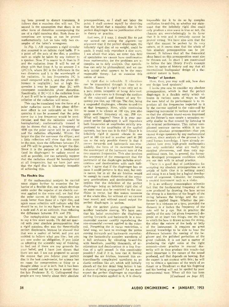
ing been proved to distort transients, it follows that a massless disc will not. The second is the assumption that there is no other form of distortion accompanying the use of a rigid massless disc. Both these as- sumptions are wrong. as can be proved mathematically. Let us take only two ex- amples of the latter's wrongness.
In Fig. 1, AB represents a rigid circular disc mounted in an infinite rigid baffle. P is a point off the axis of the disc, a position such as might be taken by any listener to a speaker. Now P is nearer to A than to B and the radiation from B will be out of phase with that from A by an amount 2 (BC) /)., where BC is the difference in the two distances and k is the wavelength of the radiation. At low frequencies BC is small compared with ),, and the phase dif- ference is negligible; but at high fre- quencies it may be larger than BC with consequent considerable phase distortion. Specifically, if BC = % k the radiation from A and B will be in opposite phase, and can- cellation of the radiation will occur.
This can be translated into the form of a polar radiation curve. If the phase differ- ence effect is not noticeable at low fre- quencies it can be assumed that the polar curve for a low frequency would be semi- circular, and that the radiation would be hemispherical ; mathematically treated it can be shown that at, say, a frequency of 4000 cps the polar curve will be an ellipse and the radiation ellipsoidal. Worse, the larger the disc the narrower the ellipse; and a little reflection will show that this must be the case, since the difference between PA and PB will be greater, the larger the disc. Since it is the purpose of a loudspeaker (and its diaphragm) to radiate sound as well as possible, one can naturally suppose that the radiation should be hemispherical at all frequencies, but we have just seen that the rigid disc is inherently incapable of achieving this.
The Flexible Disc
If the mathematical analysis be carried some stages further to examine the be- havior of a flexible disc, one which develops nodes under the impulse of an electric cur- rent applied to the voice coil, we find that the polar curves at high frequencies are much better than those of a rigid disc, and again some reflection will indicate why this should be so, for in my figure B may be on a node and A at an antinode, thus reducing the difference between PA and PB.
Our metaphysician may now be allowed to say a few more words. He did not quar- rel with your absolute presupposition that a rigid massless disc was the theoretically perfect diaphragm, because he showed that that was a matter of belief, and you are entitled to believe what you like; but you are now under an obligation, if you insist on adopting the scientific way of thinking, to find out if there are any grounds for your belief, and I have just shown that there are not. I am not prepared to accept the excuse that you believe your perfect disc is the best compromise, for science has no room for compromises -a thing or a thought either is or it isn't. But it has been truly pointed out by no less a savant than the late Professor R. G. Collingwood that people are very touchy about their absolute
34
presuppositions, so I shall not labor the point. I shall content myself by observing that the belief that a massless disc is the perfect diaphragm has no justification either in theory or practice.
And now, if I may, I should like to put my second cat among the pigeons -my argument that if the perfect diaphragm, the infinitely rigid disc of no weight, could be made, it could only reproduce a sine wave. I am afraid that when we enter this field of speculation we cannot have confirmation from mathematics, for the problems are so complex as to defy analysis. Our specula- tion can only be philosophical, and we can only accept what appears to be the more reasonable theory. Let us examine this notion of mine.
A rigid disc is inflexible. If vibrations can be transmitted through it then it is flexible. Since it is rigid it can only act as a pure piston incapable of being defo °mod. Apply a sine -wave to it through the medium of the voice -coil and former of any fre- quency you like, say 100 cps. The disc, being a suspended diaphragm, vibrates to- and -fro at that frequency. Now, while continuing to cause it to vibrate at 100 cps, you also apply another frequency of, say, 200 cps. What will happen? Since it is your sup- posed perfect diaphragm it will reproduce both frequencies at amplitudes strictly pro- portional to the amplitudes of the applied currents, but how can it do this? Since it is infinitely rigid it cannot vibrate in one part at 100 cps and in another part at 200 cps so the only possible theory is that it moves forwards and backwards non -sinu- soidally, the form of its movement being the counterpart of the harmonic sum of the two separate frequencies. This also involves the acceptance of the consequence that the movement of the diaphragm includes accel- erations and decelerations with each half - cycle. I agree that if the diaphragm has no mass it could perform in this way, but only in vacuo, for in air the air friction would be enough to cause distortion of the neces- sary accelerations and decelerations. This implies that the definition of the perfect diaphragm being an infinitely rigid disc of no mass must also be restricted to the con- dition in vacuo, but this makes nonsense of the whole idea, for without air we cannot hear sound, and without sound output the perfect diaphragm is useless.
But the perfect piston protagonist has another headache coming. We have seen that his belief necessitate.: the diaphragm moving forwards and backwards in a non - sinusoidal manner exactly reproducing the non- sinusoidal current applied to the voice - coil. Forgetting the in vacuo restriction, a fatal snag, we have to envisage the piston moving forwards and backwards reproduc- ing the fantastically complex waveform of a full orchestra by vibrating to-and -fro with hundreds, possibly thousands, of ac- celerations and decelerations in a tiny frac- tion of a split second. Is this conceivably possible? And if it is, bow can it, having escaped the air friction, transmit this ex- traordinarily complicated waveform to an elastic medium like air, which will initially absorb all the fine detail long before it has a chance of being propagated? As we must expect the perfect diaphragm to reproduce all the frequencies applied to it, it is clearly
impossible for it to do so by complex oscillation to-and -fro, so whether my state- ment that the infinitely rigid disc could only produce a sine -wave is true or not, the chances are overwhelmingly in its favor that it is true and it certainly cannot be proved wrong. We have also seen that the rigid disc cannot be perfect by its very nature, so it seems time that the whole of this absolute presupposition can be jet- tisoned. It follows that all the theoretical ideas based on this presupposition must also be thrown out. In short I am constrained to follow the late Henry Ford's example when he spoke of history and say that all conventional loudspeaker design of a the- oretical nature is bunk.
"Design" of Speakers How, then, you may well ask, how does
one design loud speakers? I invite you now to consider my absolute
presupposition, which is that the perfect diaphragm is a flexible entity which vi- brates in various sorts of ways so that the sum total of its performance is to re- produce all the frequencies imparted to it by the current applied to the voice -coil by imparting movement to various zones of air so that the ultimate sound -waves impressed on the listener's ears create a sensation ex- actly similar to that created by listening to the original performance. This rather com- plicated sentence carries within it an in- ferential absolute presupposition -that you cannot design speakers by any mathematical process, since analysis of the process is be- yond human knowledge. I have already ex- plained how even high -grade mathematics can only undertake what are really the simplest phenomena, and then only sup- positional cases, for, in general, the formu- las developed presuppose conditions which are not met with in actual practice.
There is a good deal of justification for accepting my absolute presupposition as an article of faith (for it is nothing more) and using it as a basis for a logical develop- ment of argument. Consider, for example, a musical instrument such as a violin.
It is an ordinary commonplace scientific fact that the fundamental frequency of the note produced by drawing the bow across the strong is a function of the length of the string between the bridge and the per- former's applied finger. Whether the per- former is a virtuoso or a tyro, provided the distance is s inches the frequency of the note will be y cps. But in practice the quality of the note (of given frequency) de- pends on at least two things, one the way in which the bow is drawn across the string, the other the nature of the body or belly of the instrument. It requires no great musical knowledge to be able to hear the difference between the sawing of the be- ginner and the polished perfection of the great violinist. It is not just a matter of producing the right notes at the right moment -sheer practice in manual dex- terity will in time produce this result -but more important is the nature of the sound produced, and that depends on bowing. But the expert is not content with this ; he will try to obtain a specimen of the work of an Amati or a Stradivari so that his fingering and his bowing will not be spoiled by poor instrumental tone. When all this has been
[Continued on page 531
AUDIO ENGINEERING JANUARY. 1953
www.americanradiohistory.comAmericanRadioHistory.Com
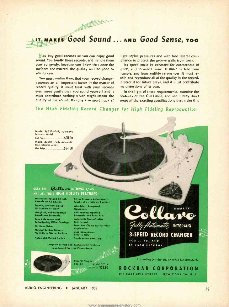
5r.-- Good Sound ... AN D Good Sense, TOO
LJ ou buy good records so you can enjoy good sound. You fondle these records, and handle them ever so gently, because you know that once the surfaces are marred, the quality will be gone to you forever.
You must realize then, that your record changer becomes an all- important factor in the matter of record quality. It must treat with your records even more gently than you could yourself, and it must contribute nothing which might impair the quality of the sound. Its tone arm must track at
light stylus pressures and with free lateral com- pliance to protect the groove walls from wear.
Its speed must be constant for correctness of pitch, and to avoid 'wow'. It must be free from rumbe, and from audible resonances. It must re- tain and reproduce all of the quality in the record, protect it for future plays, and it must contribute no distortions of its own.
In the light of these requirements, examine the features of the COLLARO, and see if they don't meet all the exacting specifications that make this
The High Fidelity Record Changer for High Fidelity Reproduction
Model 3/522 -Fully Automatic Intermix Model List Price $65.00 Model 3 /521 -Fully Automatic Non- Intermix Model List Price $54.50
ONLY THE . '' . ,, INTERMIX 3/522 HAS ALL THESE ' DELITY FEATURES:
10 and 121na Records at All Speeds.
Steady, Constant Speeds - No Rumble or Wow.
Weighted, Rubber -matted, Rim- driven Turntable.
Four Pole Motor with Self- aligning Oilite Bearings.
No Hum Pickup.
Molded Rubber Drives - No Belts to Slip or Replace.
Automatic Muting Switch.
lus ressitra . ant - Tracks at as little as 3 crams.
Absolutely Jam -proof Operation. Ball- bearing Mounted Turntable and Tone Arm. Automatic Shut-off after Last Record.
Tone Arm Clamp for Portable Applications. Base Dimensions: 143" x 1214"
Depth Below Base: 21"
Complete Service and Replacement Facilities Maintained for your Convenience.
Model 3 522
FOR 7, 10, AND 12 INCH RECORDS
Record Player Model 3;'514
list Price $33.60
AUDIO ENGINEERING JANUARY, 1953
At Leading Distibutors, or Write for Literature.
ROCKBAR CORPORATION 211 EAST 37th STREET NEW YORK 16, N. Y.
www.americanradiohistory.comAmericanRadioHistory.Com
The Protection of Ideas ALBERT WOODRUFF GRAY
Legal aspects of creative thought are also important to engineers.
THE SUGGESTION for an improvement in radio cabinets, accompanied by sketches of the proposed innovation
was submitted to a radio manufacturer by a firm of cabinet designers. Later the sketches were returned by the manufac- turer with a letter that it was not in- terested but should any of the designs be used, payment would be made on a royalty basis of 1 per cent of the cost of the cabinet, to be paid by the cabinet manufacturer.
The sketches submitted by these cabi- net designers to the radio manufacturer had no earmarks by which the designers might identify the plans as their own. When later these same features appeared in a cabinet produced by this manufac- turer, suit was brought by the designers for the value of the plans they had sub- mitted.
The defense of the company, which the court sustained, was that the design in- corporated in these cabinets was con- ceived by the president of the company from the suggestion of an automobile hood and that at no time had he ever had any knowledge of the ideas or sugges- tions submitted by these designers.
Nearly two hundred years before this incident an English judge said in the decision of a case involving the exploita- tion of ideas,
"Nothing can be the object of property that is not capable of distinguishable pro- prietary marks. The principle of this first institution of property was estab- lished to preserve the peace of mankind which could not exist in a promiscuous scramble. Therefore a moral obligation rests on all that none should intrude upon the possessions of another.
"But this obligation could only take place where the property was distin- guishable and everybody knew that it was not open to another. The breach of a duty must be willful to make it criminal. It was necessary therefore that every person should have some indicia, some distinguishing marks upon his property to denote his being the proprietary, for hard would be the law that should judge a man guilty of a crime when he had no possibility of knowing that he was do- ing the least wrong to any individual.
"Now where are the indicia or dis- tinguishing marks of ideas," asked that eighteenth century English judge. "What distinguishing marks can a man fix upon a set of intellectual ideas so as to call himself the proprietor of them? They have no earmarks upon them, no tokens of a particular proprietor."
There was lacking in these radio cabi- net designs the earmarks or indicia, men- tioned in that English decision, that
3536 76th St., Jackson Heights, N. Y.
would have aided them in the support of their claim for compensation, had the ideas for this innovation been submitted under the provisions of an agreement or contract between themselves and the radio manufacturer.
This lack of means of showing the identity, the absence of the earmarks, in circumstances of this character, was the subject of a comment by the Court of Appeals in New York state, in denying recovery to the proprietor of another idea claimed by him to have been wrong- fully appropriated by another.
"Without denying that there may be property in an idea or trade secret or system," said that court, "it is obvious that its originator or proprietor must himself protect it from escape or dis- covery. If it cannot be sold or negotiated or used without disclosure it would seem proper that some contract should guard or regulate the disclosure, otherwise it must follow the law of ideas and become the acquisition of whoever receives it."
Idea Outlined in MS.
An action before a New Jersey court involved a manuscript in which had been outlined a valuable idea but with no pro- vision for compensation to the origi- nator. The plan was adopted. Later when an action was brought to recover the value of this plan the court said of the recovery claimed by the author,
"He has undoubtedly the right to claim protection for his manuscript. The com- bination of words of which it is com- posed is also protected. The law has never attempted to go beyond this and to enjoin for the benefit of the author, after publication, the use of ideas contained in his work. In the case of secret processes of manufacturing the law does to a cer- tain extent enjoin the use of ideas. In enjoining the use of formula it restrains the wrongdoer from putting the ideas formulated to practical account. The protection ends when the secret becomes known.
"If the idea contained in a patented device of "A" suggests to the mind of "B" another idea that would not have arisen in the mind of "B" but for the stimulus of the prior idea, "A" can claim no property in that, and yet "B" has mentally appropriated "A's" idea and made it the basis of his own ; and I do not suppose it has ever been contended that the entire public are not at liberty to subject "A's" idea to such investiga- tion and discussion as it may desire.
"It was, as far as its originator was concerned, an idea, pure and simple. Now it has never in the absence of con- tract or statute, been held, as far as I am aware, that mere ideas are capable of legal ownership and protection."
In a later opinion rendered in this same litigation the New Jersey court made this supplementary comment, "Un- doubtedly ideas, if valuable or even thought to be valuable, may be the sub- ject of bargain and sale. They may be the subject of contract but they must be protected by contract."
An idea once released by publication freed for the use of whomsoever may so wish, like a wild animal freed from its cage, can be the property of no one. Substitute for a cage a contract and for the bird or beast of the outdoors, an idea, and the analogy is complete. In every instance thee must be a contract, either express or implied. Lacking that the idea is irrecoverable when once it has gone from its owner.
An idea was submitted to a manufac- turer who had made no agreement for payment and the outline of this idea was unaccompanied either by drawings or the findings of experimental work.
If the manufacturer derived benefit from the idea, asserted the federal court denying to the originator of this idea a recovery, it is nevertheless not indebted to this originator because it did not offer to or make any agreement to pay for such mere suggestions as the possessor of this idea made. When he voluntarily divulged his mere idea and suggestion, whatever interest he had in it became common property and was available to the manufacturer.
A contract protecting an idea against exploitation and loss must obviously precede the disclosure of the idea itself. The idea, however, must be thus pro- tected in its disclosure but it must be novel to the recipient and of a substantial value to him.
"When information is proffered as consideration for a contract it is neces- sarily implied -it is indeed the essence of the proffer that the information shall be new to the one to whom it is prof- fered," said the Connecticut Supreme Court in its decision of a case of this character.
"A statement to one of what he already knows is not, as to him, information but merely a statement of fact already known. The imparting of information in a situation like this must involve an active process, resulting in arousing or suggesting ideas or notions not before existent in the minds of the recipient, otherwise it is not information in the true sense of the 'term, although it may be a statement of fact."
In Indiana some years ago an idea or scheme was submitted with a letter that said, in substance, that the plan was sub- mitted for approval. This was followed by an outline of the scheme and the letter concluded with, "I trust that this idea
[Continued on page 51]
36 AUDIO ENGINEERING JANUARY, 1953
www.americanradiohistory.comAmericanRadioHistory.Com
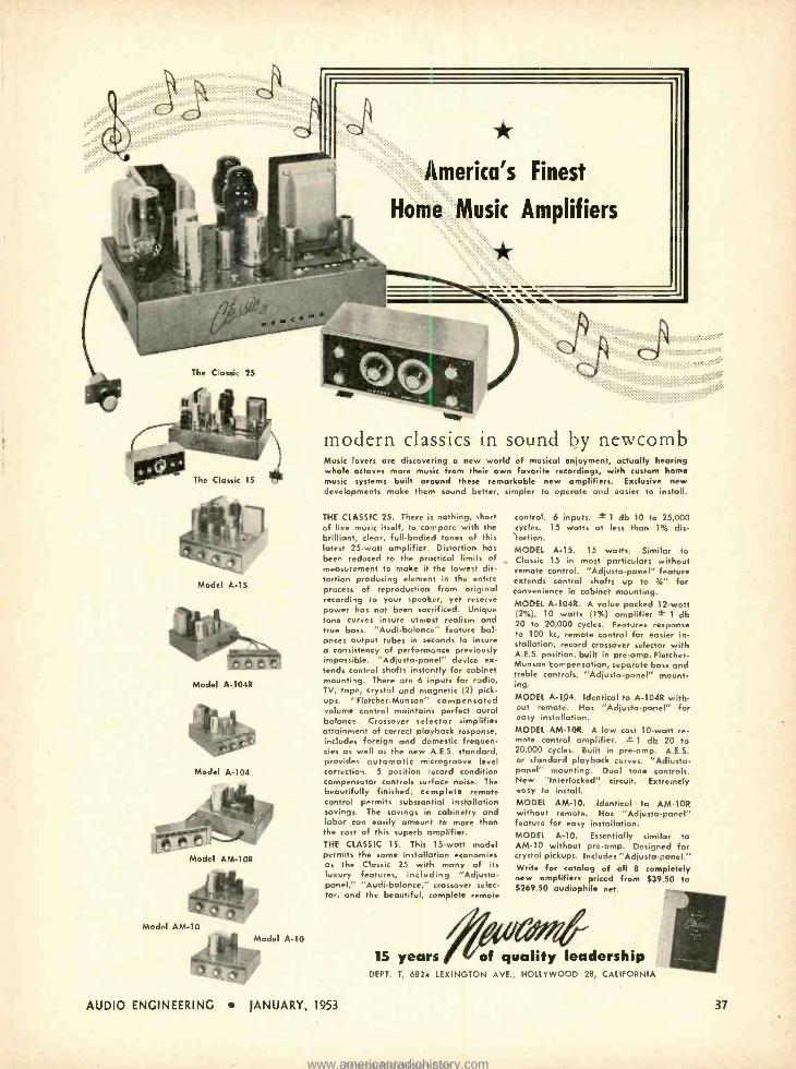
America's Finest
Home Music Amplifiers
*
The Classic 25
The Classic 15
Model A -15
Model A -104R
Model A -104
Model AM -10R
modern classics in sound by newcomb Music lovers are discovering a new world of musical enjoyment, actually hearing whole octaves more music from their own favorite recordings, with custom home music systems built around these remarkable new amplifiers. Exclusive new developments make them sound better, simpler to operate and easier to install.
THE CLASSIC 25. There is nothing, short of live music itself, to compare with the brilliant, clear, full- bodied tones of this latest 25 -watt amplifier. Distortion has been reduced to the practical limits of measurement to make it the lowest dis- tortion producing element in the entire process of reproduction from original recording to your speaker, yet reserve power has not been sacrificed. Unique tone curves insure utmost realism and true bass. "Audi- balance" feature bal- ances output tubes in seconds to insure a consistency of performance previously impossible. "Adjusta- panel" device ex- tends control shafts instantly for cabinet mounting. There ore 6 inputs for radio, TV, tape, crystal and magnetic (2) pick- ups. "Fletcher- Munson" compensated volume control maintains perfect aural balance. Crossover selector simplifies attainment of correct playback response, includes foreign and domestic frequen- cies as well as the new A.E.S. standard, provides automatic microgroove level correction. 5 position record condition compensator controls su-face noise. The beautifully finished, ccmplete remote control permits substantial installation savings. The savings in cabinetry and labor can easily amount to more than the cost of this superb amplifier. THE CLASSIC 15. This 15 -watt model permits the same installation economies as the Classic 25 with many of its luxury features, including "Adjusta - panel." "Audibalance," crossover selec- tor, and the beautiful, complete remote
AUDIO ENGINEERING JANUARY, 1953
control. 6 inputs. ± 1 db 10 to 25,000 cycles. 15 watts at less than 1% dis- tortion. MODEL A -15. 15 watts. Similar to Classic 15 in most particulars without remote control. "Adjusts- panel" feature extends control shafts up to 34" for convenience in cabinet mounting. MODEL A -104R. A value packed 12 -watt (2 %), 10 watts (1 %) amplifier ± 1 db 20 to 20,000 cycles. Features response to 100 kc, remote control for easier in- stallation, record crossover selector with A.E.S. position, built in pre -amp, Fletcher - Munson compensation, separate bass and treble controls, "Adjusta- panel" mount- ing. MODEL A -104. Identical to A -104R with- out remote. Has "Adjusta- panel" for easy installation. MODEL AM -10R. A low cost 10 -watt re- mote control amplifier. f 1 db 20 to 20,000 cycles. Built in pre -amp. A.E.S. or standard playback curves. "Adiusta- panel" mounting. Dual tone controls. New "Interlocked" circuit. Extremely easy to install. MODEL AM -10. Identical to AM -10R without remote. Has "Adjusta- panel" feature for easy installation. MODEL A -10. Essentially similar to AM -10 without pre -amp. Designed for crystal pickups. Includes "Adjusta- panel." Write for catalog of all 8 completely new amplifiers priced from 539.50 to $269.50 audiophile net.
15 years / V of quality leadership DEPT. T, 6824 LEXINGTON AVE., HOLLYWOOD 28, CALIFORNIA
37
www.americanradiohistory.comAmericanRadioHistory.Com
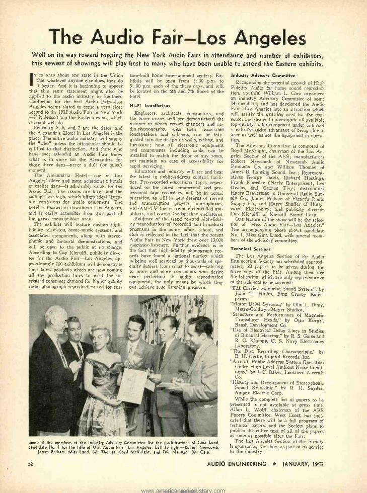
The Audio Fair -Los Angeles Well on its way toward topping the New York Audio Fairs in attendance and number of exhibitors, this newest of showings will play host to many who have been unable to attend the Eastern exhibits.
Ii is suo about one state in the Union that whatever anyone else does, they do it better. And it is beginning to appear
that this same statement might also be applied to the audio industry in Southern California, for the first Audio Fair -Los Angeles seems slated to come a very close second to the 1952 Audio Fair in New York -if it doesn't top the Eastern event, which it could well do.
February 5, 6, and 7 are the dates, and the Alexandria Hotel in Los Angeles is the place. The entire audio industry will supply the "who" unless the attendance should be entitled to that distinction. And those who have ever attended an Audio Fair know what is in store for the Alexandria for those three days -never a dull (or quiet) moment.
The Alexandria Hotel -one of Los Angeles' older and most aristocratic hotels of earlier days -is admirably suited for the Audio Fair. The rooms are large and the ceilings are high, which offers ideal listen- ing conditions for audio equipment. The hotel is located in downtown Los Angeles, and is easily accessible from any part of the great metropolitan area.
The exhibits will feature custom high - fidelity television, home -music systems, and associated components, along with stereo- phonic and binaural demonstrations, and will be open to the public at no charge. According to Cap Kierulff, publicity direc- tor for the Audio Fair -Los Angeles, ap- proximately 100 exhibitors will demonstrate their latest products which are now coming off the production lines to meet the in- creased consumer demand for higher quality radio -phonograph reproduction and for cus-
tom -built home entertainment centers. Ex- hibits will be open from 1: 00 p.m. to 9:00 p.m. each of the three days, and will be located on the 6th and 7th floors of the hotel.
Hi -Fi Installations
Engineers, architects, contractors, and the home owner will see demonstrated the manner in which record changers and ra- dio- phonographs, with their associated loudspeakers and cabinets, can be inte- grated into the design of walls, ceiling, and furniture; how all electronic equipment and components, including cable, can be installed to match the decor of any room, yet maintain an ease of accessibility for rapid servicing.
Educators and industry will see and hear the latest in public- address control facili- ties. Pre -recorded educational tapes, repro- duced on the latest commercial and pro- fessional tape recorders, will be in actual operation, as will be new designs of record and transcription players, microphones, FM -AM -TV tuners, remote -controlled am- plifiers, and corner loudspeaker enclosures.
Evidence of the trend toward high -fidel- ity reproduction of recorded and broadcast programs in the home, office, school, and club is reflected in the fact that the recent Audio Fair in New York drew over 13,000 spectator- listeners. Further evidence is in the fact that high -fidelity phonograph rec- ords have found a national market which is being well serviced by thousands of spe- cialty dealers from coast to coast -catering to more and more consumers who desire near perfection in audio reproduction equipment, the only means by which they can achieve true listening pleasure.
Some of the members of the Industry Advisory Committee list the qualifications of Gina Lund, candidate No. 1 for the title of Miss Audio Fair -Los Angeles. Left to right- Robert Newcomb,
lames Pelham, Miss Lund, Bill Thomas, Boyd McKnight, and Fair Manager Bill Cara.
38
Industry Advisory Committee Recognizing the potential growth of High
Fidelity Audio for home sound reproduc- tion, youthful William L. Cara organized an industry Advisory Committee of some 14 members, and has developed the Audio Fair -Los Angeles into an attraction which will satisfy the growing need for the con- sumer and dealer to investigate all available top -quality audio equipment under one roof -with the added advantage of being able to hear as well as see the equipment in opera- tion.
The Advisory Committee is composed of Boyd McKnight, chairman of the Los An- geles Section of the AES ; manufacturers Robert Newcomb of Newcomb Audio Products Co. and William Thomas of James B. Lansing Sound, Inc. ; Represent- atives George Davis, Richard Hastings, Frank Koessler (Neely Enterprises), Lee Owens, and George Tivy; distributors Harry Braverman of Universal Radio Sup- ply Co., James Pelham of Figart's Radio Supply Co., and Harry Shaffer of Holly- wood Electronics ; and publicity director Cap Kierulff, of Kierulff Sound Corp.
One feature of the show will be the selec- tion of "Miss Audio Fair -Los Angeles." The accompanying photo shows candidate No. 1, Miss Gina Lund, with several mem- bers of the advisory committee.
Technical Sessions
The Los Angeles Section of the Audio Engineering Society has scheduled approxi- mately 20 papers to be given during the three days of the Fair. Among them are the following. which are only representative of the subjects to be covered: "FM Carrier Magnetic Sound System ", by
John T. Mullin, Bing Crosby Enter- prises.
"Motor Drive Systems," by Olin L. Dupy, Metro -Goldwyn -Mayer Studios.
"Structure and Performance of Magnetic Transducer Heads," by Otto Kornei, Brush Development Co.
"Use of Electrical Delay Lines in Studies of Binaural Hearing," by R. S. Gales and R. G. Klumpp, U. S. Navy Electronics Laboratory.
"The Disc Recording Characteristic," by E. H. Uecke, Capitol Records, Inc.
"Aircraft Public Address System Operation Under High Level Ambient Noise Condi- tions," by J. C. Baker, Lockheed Aircraft Co.
"History and Development of Stereophonic Sound Recording," by R. H. Snyder, Ampex Electric Corp. While the complete list of papers to be
presented is not available at press time, Allan L. Wolff, chairman of the AES Papers Committee, West Coast, has indi- cated that there will be a full program of technical papers, and the Society plans to publish the entire text of all of the papers as soon as possible after the Fair.
The Los Angeles Section of the Society is sponsoring the show as part of its service to the industry.
AUDIO ENGINEERING JANUARY, 1953
www.americanradiohistory.comAmericanRadioHistory.Com
presto change -o .111"
If you're not using Presto discs at present, then it's time for a
change. The reason, in one word ... quality! From the meticulous
preparation of the aluminum base in the Presto plant to the
final play -back in the studio, quality is the byword ... your assurance
of consistent performance, unmatched fidelity of reproduction,
long service. That's why Presto is the proven leader in the
professional disc field ... a leader that merits your consideration
when you decide that it's time for a change ... right now.
RECORDING CORPORATION Paramus, New Jersey
Export Division: 25 Warren Street, Ne.. 'or 7, N. Y.
Canadian Division: Wolter P. Downs, Ltd.. Dominion Square Bldq !Montreal
WORLD'S LARGEST MANUFACTURER OF PRECISION RECORDING EQUIPMENT AND DISCS
www.americanradiohistory.comAmericanRadioHistory.Com
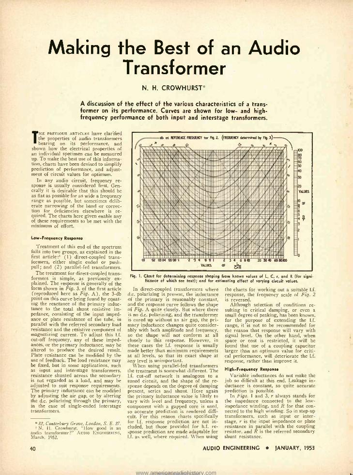
Making the Best of an Audio Transformer
N. H. CROWHURST
A discussion of the effect of the various characteristics of a trans- former on its performance. Curves are shown for low- and high - frequency performance of both input and interstage transformers.
THE PREVIOUS ARTICLES have clarified the properties of audio transformers bearing on its performance, and
shown how the electrical properties of an individual specimen can be measured up. To make the best use of this informa- tion, charts have been devised to simplify prediction of performance, and adjust- ment of circuit values for optimum.
In any audio circuit, frequency re- sponse is usually considered first. Gen- erally it is desirable that this should be as flat as possible for as wide a frequency range as possible, but sometimes delib- erate narrowing of the band or correc- tion for deficiencies elsewhere is re- quired. The charts here given enable any of these requirements to be met with the minimum of effort.
Low- Frequency Response
Treatment of this end of the spectrum falls into two groups, as explained in the first article:' (1) direct -coupled trans- formers, either single ended or push- pull ; and (2) parallel -fed transformers.
The treatment for direct- coupled trans- formers is simple, as previously ex- plained. The response is generally of the form shown in Fig. 3. of the first article (reproduced here as Fig. A), the 3 -db point on this curve being found by equat- ing the reactance of the primary induc- tance to the total shunt resistive im- pedance, consisting of the input imped- ance or plate resistance of the tube, in parallel with the referred secondary load resistance and the resistive component of magnetizing current. To adjust this l.f. cut-off frequency, any of these imped- ances, or the primary inductance, may be altered to produce the desired result. Plate resistance can be modified by the use of feedback. The load resistance may be fixed, but in some applications, such as input and interstage transformers, resistance shunted across the secondary is not regarded as a load, and may be adjusted to suit response requirements. The primary inductance can be modified by adjusting the air gap, or by altering the d.c. polarizing through the primary, in the case of single -ended interstage transformers.
* 82, Canterbury Grove, London, S. E. 27. 1 N. H. Crowhurst, "How good is an
audio transformer ?" AUDIO ENGINEERING, March, 1952.
40
`ä_Hh C67WeaIZerr9Ct4apautrSRtif1uSa7tar! Tstsr aflusot: sm alsasancs:rennscssaNeucusmvssassr.scnr.aeosaaors awavm, ansmtosuas.ao ouuamsrsosasa:rnrmanss>tat GILISs11.vA0tivaa'10Aaahlali.:MMatROORGUi07.1111waiinnl l'iA1111>p119s1:iaali1;1111aP4C111/AlI/QQaiisii lG111110100/i1lllllsliIlll,i®Ii11f 0 Jllilí 1®ìlSiIfi.oa;!uiali:ilielEi
IMEiINIiiSI ói11iiili1ielO1i!iliénili /
lk ` 'i¡ O°i'¡I '1 r ll'. ,,.'A`ÓlildI,i. asa vo:naaw_assaacovt.var sc® s'xsaa.a: =-Limasssstssars. unsm asasasstasssarass e ramcesa vNamssscwaaNCONe.aansmasoes>tsoisamroosv amar,r.: xaniosassLauaxrspassamavASSNties::rcommar.os:: Mi li 1 yi II: aW2\\OO ry i i ii IOJ41 sil Id OC. % 7iil :G\7S.\Clll\71117\riC1s11®i11d1y1i1r111.lCl 7CiS TZ1.'aalillfilQi.1110i!bloi1111.g111111 JD1111 iaea.iiir6iii,ei=.
1; _ iiéialdillr:! c_=?_ I' I I !'I:íl II /I7f !l-i-i '' ; :=:: ,
:.::_. _. .: --;_-.. .s-- - !.- asNiswlenssssisesnasaNaassiswSSssNSSSSislssNSSwwsssis
Fig. 1. Chart for determining response shaping from known values of L, C, r, and R (for signi- ficance of which see text); and for estimating effect of varying circuit values.
In direct -coupled transformers where d.c. polarizing is present, the inductance of the primary is reasonably constant, and the response curve follows the shape of Fig. A quite closely. But where there is no d.c. polarizing, and the transformer is cored up without an air gap, the pri- mary inductance changes quite consider- ably with both amplitude and frequency, so the shape will not conform at all closely to this response. However, in these cases the l.f. response is usually made better than minimum requirements at all levels, so that its exact shape at any level is unimportant.
When using parallel -fed transformers the treatment is somewhat different. The l.f. cut -off network is analogous to a tuned circuit, and the shape of the re- sponse depends on the degree of damping present, series and shunt. Here again the primary inductance value is likely to vary with level and frequency, unless a component with a gapped core is used, so accurate prediction is rendered diffi- cult. For this reason charts specifically for l.f. response prediction are not in- cluded, but those provided for h.f. re- sponse prediction are made adaptable for l.f. as well, where required. When using
AUDIO
the charts for working out a suitable l.f. response, the frequency scale of Fig. 2 is reversed.
Although selection of conditions re- sulting in critical damping, or even a small degree of peaking, has been known, for the purpose of extending the l.f. range, iris not to be recommended for the reason that response will vary with signal level. On the other hand, when space or cost is restricted, it will be found that use of a coupling capacitor larger than an optimum value for criti- cal performance, will deteriorate the l.f. response, rather than improve it.
High- Frequency Response
Variable inductances do not make the job so difficult at this end. Leakage in- ductance is constant, so quite accurate prediction is possible.
In Figs. 1 and 3, r always stands for the impedance connected to the low - impedance winding, and R for that con- nected to the high winding. So in step -up transformers, such as input or inter - stage, r is the input impedance or plate resistance in parallel with the coupling resistor, and R is the referred secondary shunt resistance.
ENGINEERING JANUARY, 1953
www.americanradiohistory.comAmericanRadioHistory.Com
7;aâ-
MODEL AF-821A Fehiod -his brilliant new Tuner stands Pilot's
:3- year-old, world -wide reputation for
F.roducing the most advanced communica-
tons instruments that science has yet
developed. Once enjoyed only by a select
circle o= engineers "in -the- know" ... Pilot
sensitivity, selectivity, stability - are now
tours, i-i this incomparable new PILOTUNER.
Not better tuner can be mode at any price .. .
let the Pilotuner is modest in cost, at $9995
Built by PILOT RADIO CORP. the nome that has been a
by -word for the greatest in
pevision communications equipment since 1919.
PILOTONE Amplifier Model AA -901 Designed for high fidelity audio reproduction from phonograph, AM or FM rodio, television or micro- phone input. Full Williamson circuit. A supreme amplifier with traditional Pilot quality. Priced of
$99.50
NEW! High
AMPLIFIERS
-Fidelity PILOTONE
and PRE -AMPLIFIER
PILOTONE Amplifier Model AA -902 A compact, medium price, high fidelity unit for use where cabinet or other mounting space is limited. Can be operated with PILOTUNER model 0-821 and similar tuners for FM -AM radio, television or phonograph reproduction $42.50
P.LOTONE Pre -Amplifier M>del PA -911 A companion unit for Pilctone An plifier Model AA -901 ... built up to the same ...acting stand- ards. Selector switch allows quick deice of aux- ili3ry, TV, radio or phono input:. Handsome in appearance, unsurpassed is performance. Excep-
tionally low priced at $29.95
Write Dept. 4E -I for free descriptive literature
PILOT Radio Corporation 37- 0636th Street, Long Island City, New York
AUDIO ENGINEERING JANUARY, 1953 41
www.americanradiohistory.comAmericanRadioHistory.Com
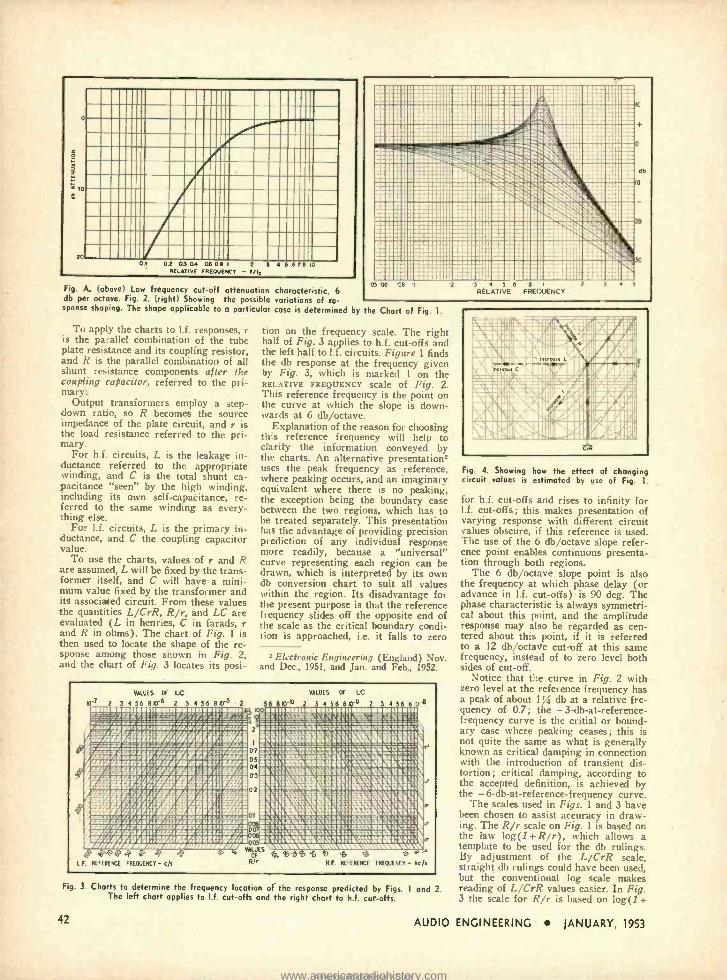
Fig. A. (above) Low frequency cut -off attenuation characteristic, 6 db per octave. Fig. 2. (right) Showing the possible variations of re- sponse shaping. The shape applicable to a particular case is determined by the Chart of Fig. 1.
To apply the charts to I.f. responses, r is the parallel combination of the tube plate resistance and its coupling resistor, and R is the parallel combination of all shunt resistance components after the coupling capacitor, referred to the pri- mary
Output transformers employ a step - down ratio, so R becomes the source impedance of the plate circuit, and r is the load resistance referred to the pri- mary.
For h.f. circuits, L is the leakage in- ductance referred to the appropriate winding, and C is the total shunt ca- pacitance "seen" by the high winding, including its own self -capacitance, re- ferred to the same winding as every- thing else.
For l.f. circuits, L is the primary in- ductance, and C the coupling capacitor value.
To use the charts, values of r and R are assumed, L will be fixed by the trans- former itself, and C will have a mini- mum value fixed by the transformer and its associated circuit. From these values the quantities L /CrR, R /r, and LC are evaluated (L in henries, C in farads, r and R in ohms). The chart of Fig. 1 is then used to locate the shape of the re- sponse among those shown in Fig. 2, and the chart of Fig. 3 locates its posi-
tion on the frequency scale. The right half of Fig. 3 applies to h.f. cut -offs and the left half to l.f. circuits. Figure 1 finds the db response at the frequency given by Fig. 3, which is marked 1 on the RELATIVE FREQUENCY scale of Fig. 2. This reference frequency is the point on the curve at which the slope is down- wards at 6 db /octave.
Explanation of the reason for choosing this reference frequency will help to clarify the information conveyed by the charts. An alternative presentation2 uses the peak frequency as reference, where peaking occurs, and an imaginary equivalent where there is no peaking, the exception being the boundary case between the two regions, which has to he treated separately. This presentation has the advantage of providing precision prediction of any individual response more readily, because a "universal" curve representing each region can be drawn, which is interpreted by its own db conversion chart to suit all values within the region. Its disadvantage for the present purpose is that the reference frequency slides off the opposite end of the scale as the critical boundary condi- tion is approached, i.e. it falls to zero
2 Electronic Engineering (England) Nov. and Dec., 1951, and Jan. and Feb., 1952.
la'r 2
VALUES OF LC
3 4 56 8 p'6 2 5 4 56 8 q -5 2 woEaIlINNlIPANaaNIIpNNaalll 6 8113-
VALUES
2
OF LC
3 4 56 810 2 S 4 56 8 0 3 -6 NNNPaNI1aaI11NINININNaallleP8 ----_--e-_ - _= -e -_ _sq= ne.=_e_ : .n=___a::: i.óYíóiwrw; /ri iiiüivi ,=_a::
2 i'ilüiááaiiii 5á. iwssaivaaoü Mf11lllli®N6iil 11111El9éii!1N11i1J pvsoaawauuiróiiiiiimá¡siássáCéä\aÓ aRI1rI0aaNaaRrir00//rNrl ï a7 iáúsóá úsá°°' ri1 i0=NINONNNaUitl0Nltaa WZMsNIa1600.i:r/IOS/.Ri1SINNIXi
05 oi111J®Ni1111t10.00\V\CCi11J i®ilUSil'!1//I/Y@ii!
,Iooiv,1e,,11 lif/RQ3I1131i®\Illlliliillì.`ilnillllìiR rIO2 9li!!1iïli1Qii8
1/iiiliii1Q,laisi1!ii\iaàsiil- NN9rAQAUYr11 NSOIILUNNSN.OOCNiO®i\YOOA\Imaó7mVha0CI1 a7IDlrt/jrlLirlltr NFittigN/it'iCa6[IIdVaYaaallNlaa\tlYaa3tl 7Li.raAnauF / 1 aaanNlJ.n, , .o,iaatNlSanII31®>oiNOaal.e .TadII(IS01i1Awoi111iAB1 iCi'tIROwMA\1111\i1R1i!il:iil /ar/Aar-./a' ___NNa_ vuuES
0° ,.° o° Y ' ^i ti o oF 4+ `6 $ ̀ b so 5 o ro n'
1F. REFERENCE FREQUENCY - c/s Rh H.F. REFERENCE FREQUENCY - kc s
Fig. 3. Charts to determine the frequency location of the response predicted by Figs. 1 and 2. The left chart applies to I.f. cut -offs and the right chart to h.f. cut -offs.
42
Fig. 4. Showing how the effect of changing circuit values is estimated by use of Fig. 1.
for h.f. cut -offs and rises to infinity for l.f. cut -offs; this makes presentation of varying response with different circuit values obscure, if this reference is used. The use of the 6 db /octave slope refer- ence point enables continuous presenta- tion through both regions.
The 6 db /octave slope point is also the frequency at which phase delay (or advance in l.f. cut -offs) is 90 deg. The phase characteristic is always symmetri- cal about this point, and the amplitude response may also be regarded as cen- tered about this point, if it is referred to a 12 db /octave cut -off at this same frequency, instead of to zero level both sides of cut -off.
Notice that the curve in Fig. 2 with zero level at the reference frequency has a peak of about i % db at a relative fre- quency of 0.7; the - 3-db-at- reference- frequency curve is the critial or bound- ary case where peaking ceases; this is not quite the same as what is generally known as critical damping in connection with the introduction of transient dis- tortion; critical damping, according to the accepted definition, is achieved by the - 6- db -at- reference -frequency curve.
The scales used in Figs. 1 and 3 have been chosen to assist accuracy in draw- ing. The R/r scale on Fig. 1 is based on the law log(1 +R /r), which allows a template to be used for the db rulings. By adjustment of the L /CrR scale, straight db rulings could have been used, but the conventional log scale makes reading of L /CrR values easier. In Fig. 3 the scale for R/r is based on log(1+
AUDIO ENGINEERING JANUARY, 1953
www.americanradiohistory.comAmericanRadioHistory.Com
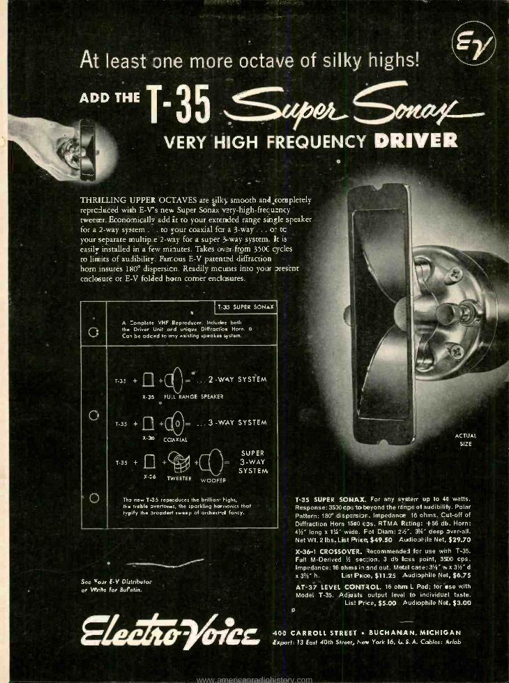
ADD THE T.3
THRILLING UPPER OCTAVES are óilky smooth and,completely reproduced with E -Vs new Super Sonax v:ry- high- frecu°ncy tweeter. Econo-nicall7 add it to your extended range single speaker for a 2 -way system . . to your coaxial fcr a 3 -way ... o- tc your separate multip e 2 -way for a super 3.-way system_ ]t ie .
easily installed in a few mi-tutes. Takes over from 350C cycles to limits of audibility. Famous E -V patented diffraction horn insures 180° dispersion. Readily mounts into your present enclnsure or E -V folded horn corner enclosures.
G
T 35 SUPER SONAX I
A :omplete VHF Reproducer. Includes both the Driver Unit and unique Difractoe Horn. o Ca, be adced to any existing speaker system.
0
e
T -35 + II + _... 2 -WAY SYSTEM
X -35 FUT. RANGE SPEAKER °
T -35 + II +(' U j= ... 3 -WAY SYSTEM
X -36
COAXIAL
¡aa 1 SUPER
T.35 + II +` 0# + )=
3 -WAY so. SYSTEM "6 TWEETER WOOFEF
Th- new T35 repeoduces the brillian highs, the treble overtones, the sparkling harmonics that typify the aroade t. sweep of orchest -al fancy.
See 'oir E -V Di:tributo: or Wri'e for Buretin.
ACTUAL
SIZE
T -35 SUPER SONAX. For any system up to 40 watts. Response: 35)0 cps to beyond the range of audibility. Polar Pattern: 180° dispersibr. Impedance 16 ohms. CA-off of
Diffraction Horn 1510 cos. RIMA Rating: +56 db. Horn: 41/2" long x 1';r" wide. Fot Diam: 2/:'. 3%" deep over -all. Net Wt. 2 lbs. List arice, $49.50 Audiophile Net, $29.70
X -36-1 CROSSOVER. Recommendei for use wi-h T -35.
Full M- Derived '/: sec: on. 3 db Icss polit, 3500 cps. Impedance: 16 ohms ii and out. MetEl case: 31/4" w x 31/2" d
x 33/e" h. List Price, $11.25 Audiophile Ne:, $6.75
AT -37 LEVEL CONTROL. 16 ohm L Pad; for use with Model T -35. Adjusts output level to incividurl taste.
Lis: Pr ce, $5.00 Audiophile Net, $3.00
40') CARROLL STREET BUCHANAN, MICHIGAN Export: 13 East 40th St: ee -, New York 16, L.:;. A. Cables:.Arlab
www.americanradiohistory.comAmericanRadioHistory.Com
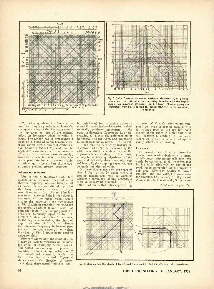
1000
04
Zpp,/z ß'5 Yi 6 8I 2 5.4 56 8 10 20 5040
VALUES OF 2 1 Kn .p . . . ., Kn ` , ; e e iiir
9. .411411111014, 10,10111. ÁW'ÌP iCiri` ä[tR q.6>-{pÑ dT9 aaaL/.C" '6!A.%O'.IS7'wiY.7ef\aa6TRq.7OLVy'`:,TSOAIY' AWES ar;.eC;s>:o-arltrduOL:IQOVsRD'u:óalar p.:c7 6::r.pYl , ,1P):pa5`Pa óa11>REEe.OZD CGtá r i Q.gSQraO'>.C:O. 14a2a5oZ41.9.NAAp4ïsa.diRëGli.O;Oo.0`,:
4 R' r rcp vr - , Báá éRéii'/'.d°á9 es ° '. -1 .. :. w .o, eÁ s iiiw:. s:.iwi ..v i.:>: ì.i iwi.:..iu :vb..;.ía:i .C.\f:C:RAVPO..@-iaLi\%::r-rßgO.L:1'Jl.ti T9..<CJ>i amn.svz11-va74ZIP,oraor,c.ca.,XI.vwro:s..d1c.QLV=a.r.m. i2CeaasA.8W.1:iaC7C.i.O:e.:a/Or/riD:iOiia,T,6.tT,L;
1Z7íCt;ESr,MMOp3ri CR9:rwC:6:0.KO.ilO:Sr,.X:: i;QRIP3o.ai >Är`.a:oop0.: ,se.altia.w,gw.s af r`<rYr've y4t-4.'"`rg¢4 .d/' i.Pú1ßi,i;!lié,f'wÓO.e4P,RtO I':rl :'.r Y i>i"r9i,'9 gY ,r..ÿ y<il/..®>ópwwlydioi`o!®'I °f . :wQfYy I .dhLEi w i : :éá . rW ..
' "` ÿ1r°wù..:ur.w:.risv..m..ñi. iilw%1 áxwó%e%-a ."LrT. :2.aa:CiifiTdLT.S:T.LiC.Ci.r.'= i`+Ü:.4gÌ>'o:ar.cttaava..RfT.iai7 ̀ wR 4 i: r.{&TiS =a.CkwV ,r0:0itt!'r6Cmm14i'0kPi:y:t:+tT i2? a0;9:`+,.. .Rí'ddlb.r> s Ó4 s.y a a .d.....c.. r >iR° ¡r ;, { k' r t' x > <r >'ß° vr -4 -+:'v ;;r,qia`l,yc<::>PQEélbwiúLSiir.s.ti:e..
iGj áÓa,F ,fpQqq1aá°fKd< IÌ.vY.ñQaI.''av/i.ryi:a31. . e./ RiS,e. I. .a suns sswslswslaaaruaeswwBal ssiw us wsasswss,
40 5060 80 100 Kn , , VALUES a Rp
ALOES
OF
I rr.srrr.wrreaar o a d, q
a81S
r /R), allowing straight rulings to be used for frequency reference. Here the cramped spacing of the R/r scale toward the top gives an idea of the reduced effect on frequency when its value is large. The author has in preparation a book on the use of audio transformers, using charts with a different configura- tion again: a cut -out log scale can be applied to show the effect of variation in R, r, L, or C values more definitely ;
however, it was felt that this idea was not appropriate for a magazine article, so advantage is here taken of the con- struction yielding greater accuracy.
Adjustment of Values
Use of the 6 db /octave slope fre- quency as a reference does not mean that the frequency does not change at all as circuit values are altered, but that the change is easier to visualize or as- sess. If either r =0 or R= oo (the for- mer never occurs and the latter seldom), variation of the other value would change the response in the way shown at Fig. 2 without changing the reference frequency. Values of R and r such that both contribute to the damping push the reference frequency upwards for h.f. circuits or downwards for l.f. circuits. to the degree indicated by the chart of Fig. 3. Variation of L or C will change the reference frequency in inverse pro- portion to the square root of their value, the chart of Fig. 3 again being used to calculate this.
Figure 4 shows how the chart of Fig. I may be used to visualize or estimate the effect of changing circuit values. The dotted lines on Fig. 1 represent a condition where L, C and either r or R are maintained constant, while the fourth quantity is varied. Figure 4 shows clearly the direction of move- ment along these dotted lines (or paral-
111I111 !iiiI!Iii 111111 1 11IIII%'' a .í91E 111111 1 iiIiIIr r.eill.,ilIiM eiuiír,.ae,G iecte OC11E1 . ./il1ells , 111111a Ilea.I:III I/rjlv:é:: l,,aal,ae:aaa sv.asssr/iel.o,e.Äe:,;%:sia, r.tens.t,,:sweoeäaa i. aea>7.asiatww seaaass s#f1i/I.aAS,se7saM\\ al7as.`0lew
IsTrAgir 3
I1proormilipir 1 Io,ra,1,0%% 'ÍI i.6lì1 ;,' !; w.ness swwnesswsssw tassaw
Fig. 5 (left). Chart to determine maximum efficiency, ii, of a trans- former, and the ratio of actual operating impedance to the imped- ance giving maximum efficiency. Fig. 6 (above). Chart applying the information from Fig. 5 to find the actual efficiency at the operating
impedance.
tel with them) for increasing values of r and R respectively -decreasing values naturally produces movement in the opposite directions. Increasing L, or de- creasing C, moves the reference point horizontally to the right, and increasing C, or decreasing L, moves it to the left.
In h.f. circuits, L is set by leakage in- ductance, but C can be increased by the addition of shunt capacitance across the high- impedance winding. In l.f. circuits, L may be variable by adjustment of the gap, and definitely does vary with sig- nal level; C, the coupling capacitor, can be made any desired value.
No provision is made on the chart of Fig. 1 for R = oo . In cases where a step -up transformer may be working without a secondary loading resistor, a high value may be assumed. It will be noted that the dotted lines representing
variation of R, with other values con- stant, converge to become parallel with db rulings towards the top left hand corner of the chart. A high value of R will produce a reading in this area, where its precise value will not appre- ciably affect the db reading.
Efficiency
In transformer circuitry. insertion loss is more readily dealt with in terms of efficiency. Percentage efficiency can easily be converted to db insertion loss by log table, slide -rule, or one of the ready made conversion tables frequently published. Efficiency relates to power transfer -and not voltage transfer -so for example, an efficiency of 60 per cent is an insertion loss of 4 db, 90 per cent
[Continued on page 74]
Al I. 1111 OEM 1\'\111111111 11111 II NflliÌl Minn NEI 1111 I%II//iÍl 11117\Fi\1111.111 w ' 11Wtreni E anunLw musuuww un.uiüesn savvn.ussum vnuraitr,.n .....,...,..w. ....,.
biN ! I I II If/ iI111 iL,1 rar 11li1,1; ;\ \I Pfi:%lIú111
Fig. 7. Showing how the charts of Figs. 5 and 6 are used to find the efficiency of a tronsforme,.
44 AUDIO ENGINEERING JANUARY, 1953
www.americanradiohistory.comAmericanRadioHistory.Com
HARVEY the House of Audio
STROMBERG -CARLSON FM -AM RADIO TUNER
Model SR -401
An unusually high quality tuner with separate FM and AM sections, using variable permeability on FM, vari- able capacitance on AM, and a sensitive bar -type tuning eye. Delivers 3 volts across a .25 megohm load with less than 1% total harmonic distortion. Has
5 microvolt sensitivity for 30 db. of quieting. Frequency response is 20 to 20,000 cps flat within 11/2 db. on the FM band. Four knobs furnish the following controls: VOLUME combined with Power Switch ... FM and AM SELECTOR with choice of Band Pass or Narrow Band selectivity on AM ...AFC "on /off' SWITCH ... and TUNING FM and AM Station Selector. Dimen- sions: 111 /4" long, 61/2" high, and 11" deep.
$ 3095 Complete with 12 tubes 9
STROMBERG - CARLSON 10 -WATT
HI -FI AMPLIFIER Model AR -410
A high quality amplifier, ideal for medium power requirements such as found in home installations. Power output is 10 watts with less than 1% total harmonic distortion, and response is
flat from 20 to 20,000 cps. within 1 db. Has a hum balancing control, and attains a hum level 70 db. below full rated output. Six input jacks for the following front ends: Low Level and High Level Magnetic Phono Cartridges ... Low Level and High Level
Radio Tuners ... Low Level Microphone ...and Auxiliary for TV, Tape Recorder, Crystal Pickup, etc. Four knobs provide front panel controls: SELECTOR SWITCH for Microphone, Foreign Records, American Records, Radio, and Auxiliary... LOUD-
NESS CONTROL which compensates for Fletcher- Munson curves .. BASS CONTROL with 15 db. boost to 20 db. attenuation at
30 cycles ... and TREBLE CONTROL with 12 db. boost to 20
db. attenuation at 10,000 cycles, plus power switch. Output impedances are: 4, 8, 16, 150, and 600 ohms. Built -in pre-
amplifier /equalizer serves the record types covered by the
selector switch. Dimensions: 11" wide, 7" high, and 8" deep.
Complete with tubes: 12AU7, 12AX7, 12AT7, 2 -6F6, and 5Y3.__._.. _... _._ s7995
R -J SPEAKER ENCLOSURES BOOKSHELF MODELS
The new famous R -J cabinet developed to new dimensions. Small enough to permit it to be inconspicuously mounted on a bookcase shelf. Reproduces amazingly clean, smooth, bass fundamentals while permitting aired radia- tion of high frequencies. An ideal system
where space is at a premium or as an extension reproducer in an extra room. May be finished to match the decor.
Model S -8 -U for 8 inch speakers (11" high x 10" deep x 231/2" long) $24.50
Model S -12 -U for 8 inch speakers (24" high x 10" deep x 21" long) 29.50
WESTERN ELECTRIC 755 -A SPEAKER (Brr PM) A remarkable value, ideal for use with the R -1 Model S -8 -U.
Provides full frequency range coverage and wide angle high -
frequency distribution. SPECIAL $2460
HARVEY is the HOUSE of AUDIO Whatever it is in the fleid of Audio, you can be sure to find it at Harvey
. in stock, and ready for immedi- ate delivery wherever you may be. Your inquiries are invited. NOTE: Prices Net, F.O.B., N.Y.C. Subject to change without notice. CI) 103 W. 43rd Street, New York 36, N. Y. LUxemburg 2 -1500
The NEW
MINIFON Miniature, Portable
WIRE RECORDER
Measuring only 1% x 43/e x 6 %, and weighing only 2 lbs. 7 ozs., the Minifon is just about the world's smallest sound recording instrument. Records, rewinds, erases, and plays bock through either a pair of stethoscope type earphones or an
external amplifier. Capacity 21/2 hours uninterrupted recording. Powered by 11 /2 v. A battery, standard 30 v. B battery, and 7
Mallory RM -4Z mercury batteries. An ideal tool for executives, engineers, doctors, and wherever there is need for recording notes, interviews, and other data.
Complete with microphone, stethoscope type earphones, $250 1 hour spool of wire, tubes, batteries, and instructions. L
Morocco Leather Zipper Case...... $7.50 Transformer -rectifier Unit for operation of motor from
117 v. AC line $20.00
RECORDING WIRE On spools, in dust -proof plastic
containers, suitable for mailing.
'I, hour '/, hour
$5.00 7.00
2'/: hour
1 hour 2 hour
21.50
5 9.00 17.90
The ORIGINAL
WILLIAMSON HR -15
Amplifier Kit
The famous, original Williamson HR -15 .
still acclaimed the leader .. in kit form, with the Partridge Out- psi Transformer specified by Williamson in his original design. Assemble this kit, and in 3 hours or less, enjoy the finest sound you over heard. Operates from a tuner, phonopreamp, crystal pick -up, or other signal source. Absolute gain is 70.8 db with 20 db of feedback. Frequency response, -.5 db, from 10 to 100,000 cps. Output impedances to match all speakers from 1.7 to 109 ohms. Kit is complete with 5 tubes: 1 -5V4, 2 -6SN7, and 2 -5881 (or 807 if requested), 2- Punched Chassis, 2- Resistor
Mounting Strips, Sockets, Partridge WWFB Output Transformer, Assembly Instructions, and All Other Necessary Parts for Amplifier and Power SJpplr_. _.. ___..
_.__.... _._. ........... ............$76.50
PARTRIDGE OUTPUT TRANSFORMER WWFB - Available Separately $26.50
11R -15T Williamson Kit - Furnished as above, with TRIAD
Transformers and Chokes $69.50 NOTE: HR -15 and HR -1ST Kits may be had with British KT -66 Output tubes for $3.00 additional.
CARTER SUPER CONVERTORS Deliver clean 60 cycle AC power at 115 volts. Operate from storage batteries or other DC
source, and available for 6, 12, 24, 28, 32, 64, or 115v input voltages. Ideal for on- location recordings with quality equipment. Write for complete dota and prices.
CANNON PLUGS and CONNECTORS The standard of quality for over 15 years. You'll fend them wherever the ultimate is required in low level sound transmission, and general electrical and electronic applications. Write for complete data and prices.
COMPLETE STOCKS CARRIED AT ALL TIMES FOR IMMEDIATE DELIVERY
HARUEY RADIO COMPANY, INC.
AUDIO ENGINEERING JANUARY, 1953 45
www.americanradiohistory.comAmericanRadioHistory.Com
WHAT ABOUT all this excitement over "binaural" recording, broadcasting, reproduction ? It was only a year or
so plus some, that we first heard of com- mercially available two- channel recording, via Magnecord. At that time the "binaural" Magnecorder was no musical instrument. On the first announcement, down in a small paragraph headed HOME, there was a brief mention of the enhancement of music by twin -channel recording; but the rest of the blurb was all about industrial uses, business conference work and the like. A lot seems to have happened since then!
"Binaural" -the quotes used advisedly - was the sensation of the recent Audio Fair and the pronouncements concerning its wonders were so joyous and jubilant that many went forth astounded. A few, I regret to say, went away convinced that the whole thing was publicity. It was surely that ! The demonstrations were impressively staged and expensive, indeed a bit overpower- ing in their splendor. Wherever one went, there was "binaural," in an assortment of forms from earphones to batteries of trumpet speakers. Steam engines as big as a house snorted in and out deafeningly, shaking the rafters, ping -pong games were played twenty times life -size, musical comedies, symphonies, great organs peeled forth both loud and soft (but mostly loud), persuasive gentlemen announced, "binaur- ally," that they would now walk to the right ... and then to the left ... and few of the enthralled listeners were disturbed wten for some reason they seemed merely to tromp up and down on the same spot, vaguely located near the ceiling. Soloists performed grandly out of the Right Speaker and the Left Speaker and only a handful were heard protesting that there were two of each, like double vision. "Binaural" music for you and me was everywhere pro- claimed, but somehow the details were left a bit indefinite.
Quarter -Baked
Don't be misled -in the wrong direction -by all this "binaural" excitement, in case you have already discounted two- channel recording as one more publicity stunt. Maybe it won't be that good (nor that
* 780 Greenwich St., New York 14, N. Y.
EDWARD TATNALL CANBY* SUSPENDED IN SPACE
soon I . But there is definitely something in it, behind the big -gun stuff now going on. The trouble with "binaural" music right now is that it is scarcely begun to be de- veloped for practical use. A fine big choco- late cake, but somebody took it out of the oven quarter -baked. And the "binaural" programs at the Fair and via broadcast, in spite of some very excellent results, were in the large just that. Confusions, contra- dictions, false and faulty effects, happily swallowed up in the general excitement. Perhaps this is as it should be. We Ameri- cans usually launch our new projects in this high, wide, and handsome way. But somebody has got to untangle things sooner or later or the fine little "binaural" boomlet will collapse ... well, like a quarter -baked chocolate cake.
This department did some speculating on this question a year ago (Ai, Dec. 1951), nor was that the first time "binaural" had been injected here, an earlier and very long- winded piece of mine (1E, Jan. 1950) hav- ing had to do with the strange relations between binaural and monaural liveness, for recording and broadcast. Not a simple area at all, but the present "binaural" experi- ments have got us far more confused than ever before. I'll make only one major, fun- damental point here, to illustrate the sort of straightening out that must. be done before we know where we're going in this. Do we really mean binaural?
Binaural -Without Quotes
All recording and broadcasting is now done via one channel, with from one to n mikes and the same at the speaker end. Monaural. Illusions of reality can be ac- complished extraordinarily well, given good microphoning and good listening acoustics in the reproduction. Nothing new about that. True binaural reproduction must, how- ever, duplicate the two sounds heard by two ears -and, ideally, reproduce the effect of the original two eared listening. True binaural, effecting complete separation for each ear, is done only with earphones. The dual microphones are placed as nearly as possible to simulate a head with ears. No loudspeaker combination can possibly give a true binaural reproduction, since not only will the two channels overlap, both ears hearing both speakers, but there is a false
sense of direction injected by the fact that the speakers themselves are directionally spotted -thanks to our hearing each of them with both ears. But do we need true, literal binaural? That is an interesting question.
Simple Substitution
There is an entirely different plan of ac- tion called stereophonic sound. This plan is simple. Forget about two ears, one channel for each. Instead, use two, or three, or num- berless channels to put the sound sources spatially in the place where they ought to come from, right to the right and left to the left. With but two channels you can record a piano on one side of a stage and a singer on the other, each with his mike ;
then out speakers in place of the mikes, remove the performers and play the re- cording. You'll have them in their proper spots -because they are in their proper spots, by recorded proxy. Substitution. You can move the speakers about as if they were the performers themselves and have them "perform" in any old position you want. Nothing whatsoever to do with two - eared, binaural transmission.
For more than two performers, for a whole area of sound, more mike- record- speaker simultaneous channels are needed- theoretically an infinite number. But, as was shown 'way back in 1934 by Stokowski et al, three channels -one to each side and one for the middle -will give an excellent and close approximation of full substitution coverage. You'll find a similar system in use now for the fabled "Cinerama ". It is not binaural. No earphones! (Nor is "Cin- eramá s" picture a stereo picture-one pic- ture for each eye. Its several pictures are spread out exactly as is the sound, the simultaneous projections overlapping at the edges as do the sounds from the simul- taneous recording channels.)
20 Feet Now, my chillun', for the $64 question.
Just which of these systems are we trying to use, in our so- called "binaural" record- ing?
It should be apparent to you that we have been dabbling heavily in both, mixed to- gether. We have had something of every- thing.
46 AUDIO ENGINEERING JANUARY, 1953
www.americanradiohistory.comAmericanRadioHistory.Com
In music.
llsteni g "My wife and I drove some 400 miles to New York, just to witness that concert of yours at the Audio Fair. For over an hour we waited in line, but it was worth it. No amount of advertising could have
qual_it made me believe such a thing possible. Closing our eyes, we could not tell which was playing - the live artists or the AUDAX CHROMATIC. Thank you for this thrilling experience. It will stay a memorable event in my musical life. I am going to " (from a letter)
The revolutionary new records are so true to the original that almost any pick -up is bound to give some results ...but -it takes a reproducer of the highest order, one sensitized to the nth degree ... a CHROMATIC POLYPHASE -to bring out every subtle shading, every nuance so essential to the real music of which these discs are capable. .
Therefore .. . SEE and HEAR CHROMATIC and -YOU be the judge.
Audax costs no more than ordinary pickups One single magnetic pickup plays all home
records Only AUDAX has individually replaceable Sap-
phire or Diamond styli. Response 10 to over 15,000 cps. Needle -talk practically nil* Near -infinite compliance Phenomenal tracking
is everything.
Available with the neto compass- pivoted Audax arms and to fit record changers. Auda% arms are the simplest and most efficient yet devised
*Be sure to obtain a copy of 1953 ELECTRONIC PHONO FACTS from your distributor.
AUDAK COMPANY 500 Fifth Avenue New York 36
(.',.alors of Fine Audio -Electronic apparatus for over 25 years.
.7he JjanAarQ lxl Which Odsrs 14n 0941 and Va[aed tt
www.americanradiohistory.comAmericanRadioHistory.Com
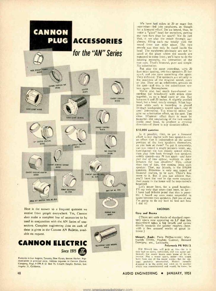
CANNON PLUG ACCESSORIES
for the "AN" Series
PIGIO GONOU,1 MAW r .
Anì053
L;nOUII GDU^LINC
ANlC,6
CAREE CLAMP AN3051
CABLE CLAMP AN7051A
CONDUIT COUPLING
6043058
90" CONOUII COUPLING
AN3062 O. CONQUIT COUPLING
6043063
B08 CONNECTOR
AN3D6E
CONDUIT COUPLING LOCANUT
ÁN3046
CONDUIT COUPLING ADAPTER
AN306B
ANrAE
DUMMY RECEPTACLE
NO. 2182
';,11
`\=J ' STRAIGHT JUNCTION
NO, nts 11
I
OUST CAP NO. 2309
W nNCt10N slot NO. n45
Here is the answer to a frequent question we receive from people everywhere. Yes, Cannon does make a complete line of accessories to be used in conjunction with the AN Series of con- nectors. Complete engineering data on each of these is given in the Cannon AN Bulletin, avail- able on request.
CANNON ELECTRIC Since 1915
Factories in Los Angeles, Toronto, New Haven, Benton Harbor. Rep- resentatives in principal cities. Address inquiries to Cannon Electric Company, Dept. A -105, P. 0. Box 75, Lincoln Heights Station, Los Angeles 31, California.
TELESCOPING GLAND BUSHING
ÁN3420
We have had mikes at 20 or more feet separation -fed into earphones, as though for a binaural effect: Do we intend, thus, to make a "giant" head for ourselves, putting our two ears thus far apart? We do just that, if we play the result through ear- phones, filling each ear totally with the sound from one mike alone. The two sounds can then only be fused inside the head. The earphones obviously are not lo- cated at the place where the sounds are supposed to come from; we'll have to do the locating mentally, via interaction of the two ears. That's binaural, pure and simple. No substitution.
But play the same recording, with 20 foot mike spacing, into two speakers 20 feet ,.part. and you nave something else again. Very different. The speakers are actually in the positions of the original sound, more or less. They act as substitutes, proxies on the spot -and this is the substitution sys- tem again. Stereophonic.
We've also had much two -channel re- cording (or broadcast) with mikes close together, as on a head more or less. Say between 6 and 20 inches. A slightly swelled head, but a head, nearly enough. W hat hap- pens when such a recording is played through loudspeakers spaced apart -say 20 feet? Interesting. The close -to mikes can give no substitution effect, on the spot. Too close. Whatever effect there is must be binaural -the interacting of the two sounds inside your head, to produce a seeming direction -if there is any direction- effect.
$10,000 question
Is it possible, then, to get a binaural effect in any degree with two speakers -i.e. an effect that is independent of the actual position of the two speakers themselves, as you look at them? To put it concretely, can you record a single person's voice, say, two -channel via two closely spaced mikes, then play him back through two speakers widely spaced -say 20 feet apart -and have just one of !tint appear, midway in space between the two speakersf This, rather than two of him, one coming from each speaker. That, my friends, is the $10,000 question. Direction is only one aspect of binaural realism, to be sure. There's lots more to it. But if you can achieve that, you'll have the rest in the same measure. And music in the home will be impressively benefited.
Let's pause here, for a good breather. I'll say only that once-just once, so far- t have had definite proof that this is possi- ble. I heard my own voice suspended in space between two speakers. Just one of me. I'm going to do my best to find out how I did it 1
RECORDS
Opry and Drama
(There are such floods of standard reper- tory opera now appearing on LP that this department takes a big breath and swims dizzily towards the quieter reaches -here- with a few unusual works of great in- terest.)
Mozart, Zaide. Paris Philharmonic; Mat - tiwilda Dobbs, Hughes Cuénod, Bernard Demigny, etc., Leibowitz.
Polymusic PR 901/2 Old Mozart fans will gulp at this -for it is
only half an opera, unfinished, and was never per- formed; few music lovers even know of its ex- istance. Not a minor opera, either -this would have been one of the major works ; but for rea- sons probably commercial, Mozart casually dropped it fn the midst and went on to another which was commissioned and would, he knew, be
48 AUDIO ENGINEERING JANUARY, 1953
www.americanradiohistory.comAmericanRadioHistory.Com
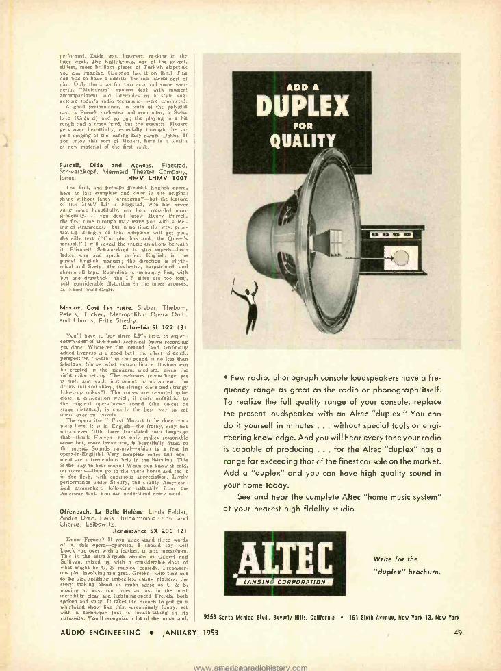
performed. Zaide was, however, re-done in the later work, Die Entführung, one of the gayest. silliest, most brilliant pieces of Turkish slapstick you can imagine. (London has it on ffrr.) This one was to have a similar Turkish harem sort of plot. Only the arias for two acts and some won- derful "Melodram " -spoken text with musical accompaniment and interludes in a style sug- gesting today's radio technique -were completed.
A good performance, in spite of the polyglot cast, a French orchestra and conductor, a Swiss hero (Cuénod) and so on; the playing is a bit rough and a trace hard, but the essential Mozart gets over beautifully, especially through the su- perb singing of the leading lady named Dobbs. If you enjoy this sort of Mozart, here is a wealth of new material of the first rank.
Purcell, Dido and Aeneas. Flagstad, Schwarzkopf, Mermaid Theatre Company, Jones. HMV LHMV 1007
The first, and perhaps greatest English opera, here at last complete and done in the original shape without fancy "arranging' -hut the feature of this HMV LP is Flagstad, who has never sung more beautifully, nor been recorded more gracefully. If you don't know Henry Purcell, the first time through may leave you with a feel, ing of strangeness -but in no time the wry, pene- trating strength of this composer will get you, the silly text ( "Our plot has took, the Queen's forsook ! ") will reveal the tragic emotions beneath it. Elizabeth Schwarzkopf is also superb -both ladies sing and speak perfect English, in the purest English manner; the direction is rhyth mical and lively; the orchestra, harpsichord, and chorus all tops. Recording is unusually fine, with but one drawback: the LP sides are too long, with considerable distortion in the inner grooves, as heard wide- range.
Mozart, Cosi fan tutte. Steber, Thebom, Peters, Tucker, Metropolitan Opera Orch. and Chorus, Fritz Stiedry.
Columbia SL 122 13) You'll have to buy three LI "s here, to experi-
ence some of the finest technical opera recording yet done. Whatever the method (and artificially added liveness is a good bet), the effect of depth, perspective, "width" in this sound is no less than fabulous. Shows what extraordinary illusions can he created in the monaural medium, given the right mike setting. The orchestra seems huge, yet is not, and each instrument is ultra -clear, the drums full and sharp, the strings close and stringy (close-tip mikes ?). The voices are recorded quite close, a convention which, if quite unfaithful to the original opera -house sound (the voices at stage distance), is clearly the best way to get opera over on records.
The opera itself? First Mozart to be done com- plete here, it is in English -the frothy, silly but ultra- clever little farce translated into language that- thank Heaven -not only makes reasonable sense but, more important, is beautifully fitted to the music. Sounds natural -which is a feat in opera -in- English! Very complete notes and com- ment are a tremendous help in the listening. This is the way to hear operas When you know it cold, oil records -then go to the opera house and see it in the flesh, with enormous appreciation. Lively performance under Stiedry, the slighty American- ized atmosphere following naturally from the American text. You cant understand every word.
Offenbach, La Belle Helène. Linda Felder, André Dran, Paris Philharmonic Orch. and Chorus, Leibowitz.
Renaissance SX 206 (2) Know French? If you understand three words
of it, this opera -operetta, I should say -will knock you over with a feather, to mix metaphors. This is the ultra - French version of Gilbert and Sullivan, mixed up with a considerable dash of what might be U. S. musical comedy. Preposter- ous plot involving the great Greeks -who turn out to be side- splitting imbeciles, canny plotters, the story making about as much sense as G & S, moving at least ten times as fast in the most incredibly clear and lightning speed French, both spoken and sung. It takes the French to put on a whirlwind show like this, screamingly funny, yet with a technique that is breath.taking in its virtuosity. You'll recognize a lot of the music and,
Few radio, phonograph console loudspeakers have a fre- quency range as great as the radio or phonograph itself.
To realize the full quality range of your console, replace the present loudspeaker with an Altec "duplex." You can
do it yourself in minutes ... without special tools or engi- neering knowledge. And you will hear every tone your radio is capable of producing ... for the Altec "duplex" has a
range far exceeding that of the finest console on the market. Add a "duplex" and you can have high quality sound in
your home today. See and near the complete Altec "home music system"
at your nearest high fidelity studio.
Write for the
"duplex" brochure.
9356 Santa Monica Blvd., Beverly Hills, California 161 Sixth Avenue, New York 13, New York
AUDIO ENGINEERING JANUARY, 1953 49
www.americanradiohistory.comAmericanRadioHistory.Com
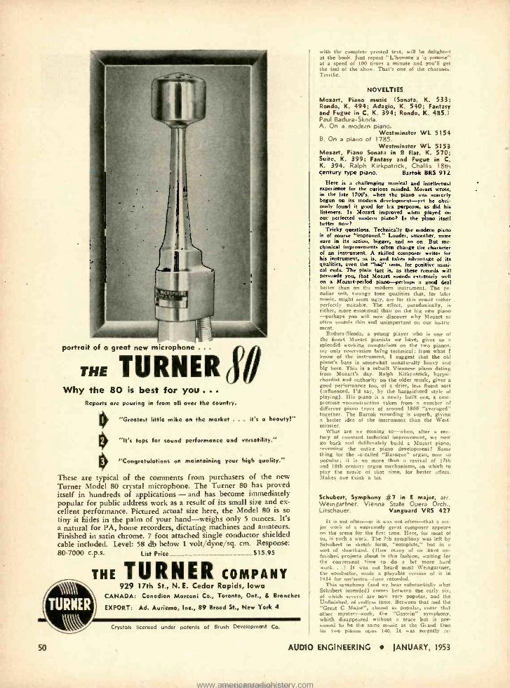
portrait of a great new microphone .. .
THE TURNER Why the 80 is best for you .. .
Reports arc pouring in from all over the country.
J'0 "Greatest little mike on the market ... it's o beauty!"
"It's tops for sound performance and versatility."
"Congratulations on maintaining your high quality."
These are typical of the comments from purchasers of the new Turner Model 80 crystal microphone. The Turner 80 has proved itself in hundreds of applications - and has become immediately popular for public address work as a result of its small size and ex- cellent performance. Pictured actual size here, the Model 80 is so tiny it hides in the palm of your hand -weighs only 5 ounces. It's a natural for PA, home recorders, dictating machines and amateurs. Finished in satin chrome. 7 foot attached single conductor shielded cable included. Level: 58 db below 1 volt /dyne /sq. cm. Response: 80 -7000 c.p.s. List Price_ $15.95
THE TURNER COMPANY
50
929 17th St., N. E. Cedar Rapids, Iowa CANADA: Canadian Marconi Co., Toronto, Ont., & Branches
EXPORT: Ad. Auriema, Inc., 89 Broad St., New York 4
Crystals licensed under patents of Brush Deveopment Co.
with the complete printed text, will be delighted at the book. just repeat "L'homme a la pomme" at a speed of 100 times a minute and you'll get the feel of the show. That's one of the choruses. Terrific.
NOVELTIES
Mozart, Piano music (Sonata, K. 533; Rondo, K. 494; Adagio, K. 540; Fantasy and Fugue in C, K. 394; Rondo, K. 485. Paul Badura -Skoda. A. On a modern piano.
Westminster WL 5154 B. On a piano of 1785.
Westminster WL 5153 Mozart, Piano Sonata in B flat, K. 570; Suite, K. 399; Fantasy and Fugue in C. K. 394. Ralph Kirkpatrick, Challis 18th century type piano. Bartok BRS 912
Here is a challenging musical and intellectual experience for the curious minded. Mozart wrote. in the late 1700's. when the piano was scarcely begun on its modern development -vet he obvi. ously found it good for his purposes, u did his listeners. Is Mozart improved when played on our perfected modern piano? Is the piano itself better now?
Tricky questions. Technically the modern piano is of course "improved." Louder, smoother, more sure in its action, bigger, and so on. But nie. chanical improvements often change the character of an instrument. A skilled composer writes for his instrument, as is, and takes advantage of its qualities, even the "bad" ones, for positive musi- cal ends. The plain fact is, as these records will persuade you, that Mozart sounds extremely well on a Mozartperiod piano -perhaps a good deal better than on the modern instrument. The pe- culiar soft, twangy tone qualities that, for later music, might seem ugly, are for this music rather perfectly suitable. The effect, paradoxically, is richer, more emotional than on the big new piano -perhaps you will now discover why Mozart so often sounds thin and unimportant on our instru- ment.
Badura-Skoda, a young player who is one of the finest Mozart pianists we have, gives us a splendid working comparison on the two pianos. my only reservation being technical: from what 1
know of the instrument, I suggest that the old piano's bass is somewhat nnnaturally heavy and big here. This is a rebuilt Viennese piano dating from Mozart's day. Ralph Kirkpatrick, harpsi- chordist and authority on the older music, gives a good performance too, of a drier, less fluent sort (influenced, I'd say, by the harpsichord style of playing). His piano is a newly built one, a com- promise reconstruction taken from a number of different piano types of around 1800 "averaged" together. The Bartok recording is superb, giving a better idea of the instrument than the West. minster.
What are we coming to -when, after a cen- tury of constant technical improvement, we now go back and deliberately build a Mozart piano, reversing the entire piano development! Same thing for the so- called "Baroque" organ, now so popular; it is no more than a revival of 17th and 18th century organ mechanisms, on which to play the music of that time, for better effect. Makes one think a bit.
Schubert, Symphony #7 in E major, arr. Weingartner. Vienna State Opera Orch., Litschauer. Vanguard VRS 427
It is not often -or it was not often -that a ma- jor work of a supremely great composer appears on the scene for the first time. Here, for most of us, is such a work. The 7th symphony was left by Schubert in sketch form, "complete," but in a sort of shorthand. ( How many of us leave un- finished projects about in this fashion, waiting for the convenient time to do a bit more .hard work...) It was not heard until Weingartner, the conductor, made a playable version of it in 1934 for orchestra- -here recorded.
This symphony (and we hear substantially what Schubert intended) comes between the early six, of which several are now very popular, and the Unfinished. of endless fame. Between that and the "Great C Major ", almost as popular, came that other mystery -work. the "Gastein" symphony, which disappeared without a trace but is pre- sumed to be the same music as the Grand Duo for two pianos opus 140. It was recently re-
AUDIO ENGINEERING JANUARY, 1953
www.americanradiohistory.comAmericanRadioHistory.Com
corded, on this assumption. in an orchestral ar- rangement approximating what Schubert intended. (Vanguard VRS 417). What a human and falli- ble man this Schubert was -his musical affairs in a constant state of semi- confusion, his fantastic musical ability pouring out new music faster than he could organize it into properly finished prod- ucts!
Both the "Gastein" and this E Major work are thoroughly big pieces; both are full of the things we know better in the familiar Schubert. If you have been captivated by the Great C Major (wrongly called #7 or #9, though it is actually #10) -or by any of the fabulous Schubert works for smaller instrumental combinations-you'll not go wrong on this one. Sympathetically, rather mellowly played by the Vinennese orchestra.
Bird Songs of Dooryard, Field and Forest. Recorded by Jerry and Norma Stillwell. 12" LP (Ficker Recording Svce.,
Old Greenwich, Conn.) The first LP bird record (though Folkways
Records has a South American Rain Forest re- cording of mingled sounds), this one follows roughly the pattern of the famous Cornell record- ings issued in 78 r.p.m. form -spoken comment introducing the birds, pointing out features of the songs, etc. The recording quality of most of these is not as good as that in the Cornell records; there is much buzzing distortion, neither the highs nor the "lows" are as clear, and the birds seem often unnaturally close. (Both recordings use the para- bolic mike extensively.) But the Stillwells have done good things, in comparing a series of differ- ent individuals of one species, in playing some songs half -speed, "slow motion," in the wealth of specific material on how to distinguish one bird from another. The long -play medium allows for greater leisure. longer excerpts. An important documentary disc as well as a most enjoyable production.
Anna Russell Sings? (Advice on Song Selec- tions for Concert Singers.
Columbia ML 4594 This dizzy dame, recorded at a "re. LI.. .
take -off genius, making delightful and very nu ., cal fun of any number of styles and manners and schools of singing. The more you know of music the more pointed her satire -but the stuff is won derful (in smallish doses) for anybody at all. Fine sense of presence, audience participation, belly laughs -on the record -until your own sides ache. Her English accent is lahvly!
PROTECTION (from page 36)
will be of sufficient value to merit a reasonable charge therefor."
No response was made to this letter but later, when the suggested idea was put into operation, the Indiana court said, holding the originator entitled to recover,
"While we recognize that an abstract idea as such may not be the subject of a property right yet when it takes upon itself the concrete form which we find in the instant case, it is our opinion that it becomes a property right subject to sale.
"Of course, it must be something novel and new ; in other words, one cannot claim any right in the multiplication table."
REFERENCES
Millar v. Taylor, 98 Eng. Reprint 201, 234 Pidot v. Zenith Radio Corp., 31 N.E. 2<I
385, Illinois Bristol v. Equitable Life Assur. Soc., 30
N.E. 506 Haskins v. Ryan, 64 Atl. 436; 78 Atl. 566,
New Jersey Lueddecke v. Chevrolet Motor Co., 70 Fed.
2d 345 Masline v. N. Y., N. H. & H. R. Co., 112
Atl. 639, Connecticut Liggett & Myers Tobacco Co. v. Meyer,
194 N.E. 206, Indiana
AUDIO ENGINEERING
ENJOY RECORDS AT THEIR BEST!
Model AI.900
RAND COMPINSATOR
EFFECTS FLAT RESPONSE
General Electric engineered to bring you as close to the beauty of the original orchestration as possible when used with standard type G -E variable reluctance cartridges.
ADJUSTABLE PLAYBACK
Five selective settings which include two scratch filter positions for noisy records.
NEW RECORD LIFE
Noticeable high frequency distortion and back- ground noise on old 78 records is greatly re- ducec. Your favorite collector's items take on a new, magic quality that rivals the original.
EASILY MOUNTED
Compact design permits mounting in any posi- tion. Easily connected between the pickup car- tridge and the pre -amplifier input.
4 17 - :7I7 t t1 Ttk-
<j "EAIIS OE ELECUICAL LL -+ PROGRESSiLLi`
SEND FOR THIS NEW BULLETIN... General Electric Com?any, Section 4413 Electronics Park, Syracuse, New York Please send me the G -E Record Compensator Bulletin with Playback Curves
NAME
ADDRESS
CITY ._
LGENERAL JANUARY, 1953
SI Al I ' ELECTRIC-I
51
www.americanradiohistory.comAmericanRadioHistory.Com
the people who know come to LAFAYETTE
Discriminating audiophiles have made Lafayette their head- quarters for the world's finest high fidelity reproduction equip- ment. Lafayette, famous for over 30 years,invites you to stop in and talk over your requirements, or write for further information on Lafayette's components for your custom installation.
CUSTOM COMPONENTS IN STOCK!
PI LOT PILOTUNER AM -FM TUNER AF -821
Coscrs Ail x,31 -1: i, mu) and F31 187.3 -108.5 roc. l Sensitivity 10 mi- crovolts for 3 volts audio output with quieting on FM and 10 microvolts for .3 volts audio output on A.N. Auto- matirfrequency control circuit can he switched in or out from front panel as needed on FM. Built -In two stage Pre-amplifier for high fidelity pluma cartridges can be switched out fur crystal phono cartridges. Separate Input lack, for phonograph and TV. With lone controls In -fiat- position audio frequency response 20 to 20.000 cps _2 db. IF response on FM 200 KC. 9KC on AM. Audio output im- pedance 7.000 ohms. Panel controls: power on -off, volume, treble. selector. bau. tuning. AFC on -of. 8 tubes plus rectifier. Completely ready to Instll with all hardware. Sire: 14,4^ x 75L', 8Ys' behind panel. 95 $99. Shp. Wt. 12 lbs. IJJ
BOGEN R701 AM-FM TUNER
Three gang tuning. dual limiter Is the FM discriminator and push but ton controlled AFC circuit provid, maximum ease of tuning and an ai, genes of drift. The AM circuit In eludes variable band -width IF channel to permit selection of wide range response or maximum aelectly- Ity. A low Impedance loop antenna is furnished. The R701 has built -in preamplifier to aCrommalste all pop- ular crystal and magnetic phono cartridges. separate bass and treble tone controls. tuning and volume controls and Input selector switch. Beautifully styled escutcheon permits easiest possible custom high fidelity Installations. Nixes: 15'x
145.21) 8ta'g 9'. Shp. Wt. 17 lbs. TI LY
52
PILOTONE HI -FI amplifier AA -901 $99.50
PILOTONE Pre -amplifier PA -911 $29.95
a, - 1°. -- E± 0 4. ,4:rc
www.americanradiohistory.comAmericanRadioHistory.Com
positive. The positive -going voltage at the plate of the second triode is the screen voltage for the 954. Thus, while the probe signal caused the 954 screen to go negative because of increased current flow, the sec- ond triode compensates for this by bringing it positive again. The amplification added by the triode to the compensating signal actually produces a positiveness which is more than proportional to the original change in 954 screen voltage. In this way, instead of going negative with increasingly positive 954 grid and cathode voltage, the 954 screen actually goes more positive than before to keep in step with its own cathode voltage. This maintains a fairly constant screen -cathode potential, preventing distor- tion for probe signals as high as 100 volts.
The four potentiometers need be adjusted only once, then locked. The idea is to ad- just them for linear operation at the highest possible input voltage.
The additional features of wideband op- eration and low input capacitance are, of course, inherent in cathode followers, but they are bettered by the screen compensa- tion as well.
A copy of any U. S. patent may be had on request from The Commissioner of Patents, Washington, D. C., for 250.
LOUDSPEAKER (from page 34)
brought together you have great music. Now it is conceivably possible that all
this complicated ritual might be scientifi- cally analyzable, but I do not think it has ever been done. The result is determined by long empirical experiment both in mak- ing the instrument and in playing it, and the excellence of the result is determined by aural testing in the presence of musical ex- perts. The Amati family, for example, found by repeated trials that a certain type of wood, cut and shaped in a certain way, assembled in a particular manner and var- nished with a lacquer of a certain composi- tion, produced violins that were esteemed by musicians, and they had not the foggiest notion of the mathematical principles un- derlying their work, nor -may we hazard a guess ?-has anyone else. Their instru- ments had a certain "tone color" which was greatly admired by violinists and musically conscious listeners, and how they got that tone color was their family secret, found out by empirical experiment.
When one comes to consider the design of a loudspeaker a similar state of affairs exists, but the aim is different. A speaker is not a musical instrument, it is a repro- ducer of musical instruments, and therefore it must have no tone color at all, otherwise its reproduction of the original music will be false. There is no way of scientifically determining beforehand how to achieve this desirable property, and when the design has been completed there is no way of finding out if the design is successful except by listening to it. And that is where the trouble starts. That is why so many musicians do not like that type of reproduction commonly called "high- fidelity." They seem to prefer the sort of distortion that one gets with "middle- fidelity" rather than the distortion one gets with high -fidelity. It is useless to point out that "high- fidelity" means free- dom from distortion, for freedom from
ON ANY STRINGED INSTRUMENT
4ecc,"fiat ge,a(ine
AMPERITE "KONTAK MIKE " THE ONLY NO- DISTORTION "KONTAK MIKE"
Anthony Anions, widely known o, "the most rorselilo artist of the i,.i,' is on nthsiosnc user of Amporito Kontok Mila.
Used with most ampli- fiers, including most electric guitar amps.
No changes in amplifier. instrument, or strings. Attached without tools.
The Amperite "Koatak Mike" improves the tone and volume of any Stringed or Fretted Instru- ment - also Pianos, Accordions, Harmonicas, etc. It is the only "Kontak Mike" that does not introduce peaks cr distortion. Model SKIP. hi -imp List $12.00 Model KKH
(with hand volu-ne control) List $18.00
AMPERITE STUDIO MICROPHONES
at P. A. PRICES! Teezetekut CLOSE TALKING
or DISTANT PICKUP You can shout right into it, or stand away; in either case, the quality will be perfectly natural. :vfodel RBLG (200 ohms). List $42.00 vfodel RBHG (hi -imp) List $42.00
r-'
AMPERITE CARDIOID DYNAMIC MICROPHONE
Mode s PGH -PGL List $32.00
AUDIO ENGINEERING JANUARY, 1953
561 Broadway New York 12, N. Y.
In Canada: Atla; Radio Corp., Ltd., 560 King St., W., Toronto
53
www.americanradiohistory.comAmericanRadioHistory.Com
76 PAGE ANTENNA CATALOG SECTION as reprinted from Radio's Master
Antennas Boosters Accessories
Catalogs the products of 32 leading Antenna and Accessory Manufac. turers
FREE! see coupon
soir r rr a .._`^4 tr
~
AcrOel'eia, a
You can obtain without cost or obligation, a com- plete 76 page antenna catalog section as reprinted from the Industry's Official 1220 page Radio's Master, 17th edition.
Whether you buy, sell or specify, you will find this handy booklet extremely helpful for quick refer- ence. It catalogs in detail the products of the leading Antenna and Accessory manufacturers with complete description., specifications and illustra- tion..
This offer i. made possible by a special ar- rangement be- tween Audio En- gineering and the publisher. of RADIO'S MASTER. Fill in the coupon NOW and a copy will be sent you by return mail.
r
4
w
Represented In RADIO'S MASTER 76 page ANTENNA and ACCESSORIES Booklet are the products of the follow Ind manufacturers:
Alliance Manufacturing Co.
Alprodco. Inc. American Phenolic Corp. Baker Manufacturing Co.
Birnbaeh Radio Co., Inc. Blonder- Tongue Labs.. Inc. Brach Mfg. Corp.
Columbia Predicts Cornell- Dublller Elec. Corp. E lectro- Voice, Inc. NI -Lo TV Antenna Corp. Insulins Corporation of Amer. J. F. D. Manufacturing Co.. Inc. LaPointe Plascomold Corp. Master Mobile Mounts, Inc. Mosley Electronics Peerless Products Industries Penn Television Products Co. Premix Products Radelco Manufacturing Co.
Radiart Corporation Radio Corporation of Amer. Radio Merchandise Sales. Int. Regency Division IA.E... Ise. Walter L. Schott Co.
South Riser Metal Prod. Co.
Spirting Products Co.. Inc. Technical Appliance Corp. Tel -A -Ray Enterprises. Inc. Tel rea. Inc. Tricraft Products Ward Products Corporation
CLIP and MAIL TODAY!
AUDIO ENGINEERING P. O. BOX 629, Mineola, N. Y.
Please send me, without cost or obligation, the 76 page AN- TENNA and ACCESSORY Booklet reprinted from Radio's Master.
Name
Addre..
City Zone .... State
distortion in that sense only implies that scientific measurement does not reveal dis- tortion. The non -musical scientist may "prove" that there is no distortion, but the musician will not be impressed with such a "proof." He will merely point out that it doesn't sound like the real thing, and that is enough for him.
Checking the Results
With this in mind we can now consider my presupposition that the speaker dia- phragm is something flexible which flaps about in the air to produce a complexity of sounds. I have shown that mathematical analysis of this is impossible, but scientific experiment has been able to lay down cer- tain desiderata. It has been shown, for ex- ample, that a restricted frequency response will not permit of satisfactory reproduction of music -there is lack of bass and wooli- ness owing to suppression of the higher harmonics of the instruments being "repro- duced" speech, also, is "plummy." Ac- cordingly, for what is called high -fidelity reproduction, a frequency range of about 50 to 15,000 cps is postulated. But in addi- tion to this there must be good reproduction of transient noises otherwise the reproduc- tion will lack what is usually termed "at- tack." Apart from wide frequency response this requirement postulates a very low de- gree of inertia in the reproducing system, otherwise it will not be able to deal with sudden impulses without delay, or return to the normal sufficiently quickly to deal with the next impulse. If we assume that the design of the amplifier has been com- pleted satisfactorily (and the design of this can be done mathematiaclly, and tested sci- entifically, because it is designed to handle electrical currents which can be measured for amplitude, frequency, phase, and trans- ient distortion) we are left with the prob- lem of designing a physical body which has to produce audible sounds which can only be partially measured.
If the speaker cannot be designed by sci- entific methods it can only be done by trial and error, and this requires a knowledge of what is required, how it can be done, and how it can be checked. Leaving out the magnet system and the voice -coil assembly, we are left with the problem of designing a diaphragm which will flap about in such a way that the sum total of its flapping is the reproduction of all musical sounds within the prescribed limits without audible distortion. How this can be done does not come within the scope of this article, but how it can be checked has already been mentioned -by listening to it. You may object that it is not fair to condemn a cer- tain technique without offering a replace- ment technique, and provided the terms of reference of the argument had not been laid down the objection would be valid.
Terms of reference were, however, laid down. They were: an injuiry into the con- tention that the perfect diaphragm should be an infinitely rigid disc of no mass is absurd and also my assertion that if such a diaphragm could be produced it could only reproduce a sine -wave. From this in- quiry emerged an argument which suggests that the mathematical design of a loud- speaker is impossible, and if this is so, then
54 AUDIO ENGINEERING JANUARY, 1953
www.americanradiohistory.comAmericanRadioHistory.Com
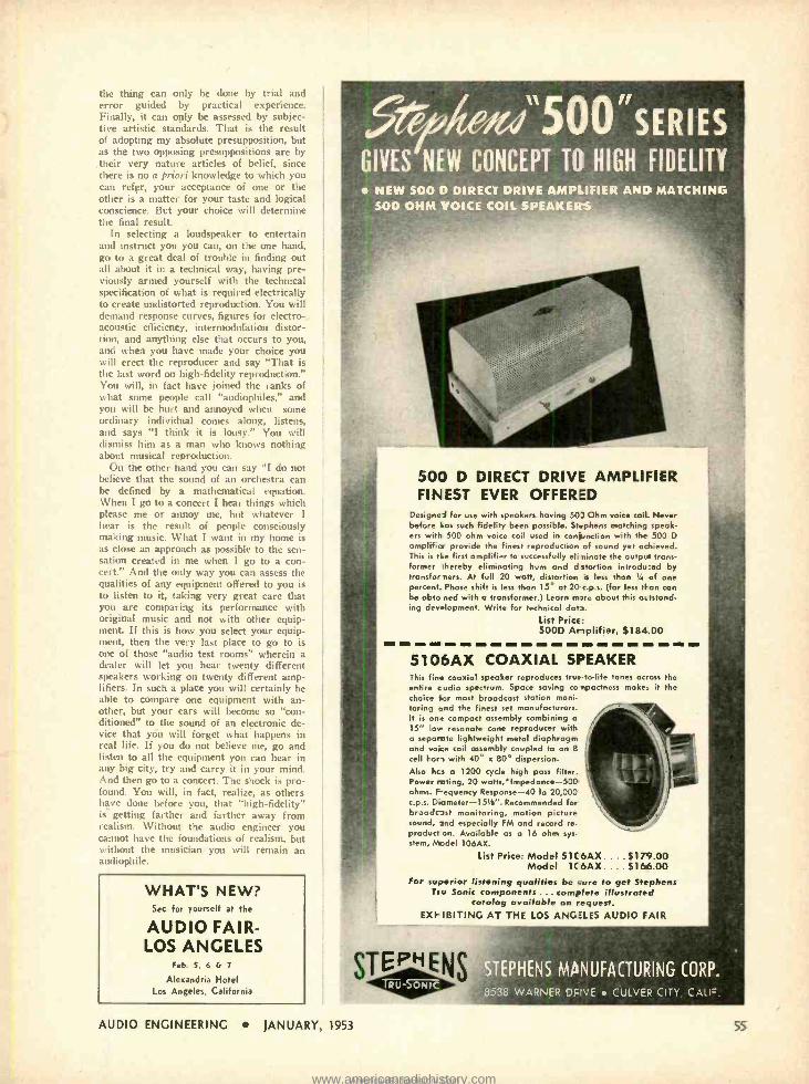
the thing can only be done by trial and error guided by practical experience. Finally, it can only be assessed by subjec- tive artistic standards. That is the result of adopting my absolute presupposition, but as the two opposing presuppositions are by
. their very nature articles of belief, since there is no a priori knowledge to which you can refer, your acceptance of one or the other is a matter for your taste and logical conscience. But your choice will determine the final result.
In selecting a loudspeaker to entertain and instruct you you can, on the one hand, go to a great deal of trouble in finding out all about it in a technical way, having pre- viously armed yourself with the technical specification of what is required electrically to create undistorted reproduction. You will demand response curves, figures for electro- acoustic efficiency, intennodulation distor- tion. and anything else that occurs to you, atitl when you have made your choice you will erect the reproducer and say "That is the last word on high -fidelity reproduction." You will, in fact have joined the ranks of what some people call "audiophiles," and you will be hurt and annoyed when some ordinary individual comes along, listens, and says "I think it i> lousy." You will dismiss him as a man who knows nothing about musical reproduction.
On the other hand you can say "I do not believe that the sound of an orchestra can be defined by a mathematical equation. When I go to a concert I hear things which please me or annoy mc, but whatever I hear is the result of people consciously making music. What I want in my home is as close an approach as possible to the sen- sation created in me when I go to a con- cert." And the only way you can assess the qualities of any equipment offered to you is to listen to it, taking very great care that you are comparing its performance with original music and not with other equip- ment. If this is how you select your equip- ment, then the very last place to go to is one of those "audio test rooms" wherein a dealer will let you hear twenty different speakers working on twenty different amp- lifiers. In such a place you will certainly be able to compare one equipment with an- other, but your ears will become so "con- ditioned" to the sound of an electronic de- vice that yóu will forget what happens in real life. If you do not believe me, go and listen to all the equipment you can hear in any big city, try and carry it in your mind. And then go to a concert. The shock is pro- found. You will, in fact, realize, as others have done before you, that "high -fidelity" is getting farther and farther away from realism. Without the audio engineer you cannot have the foundations of realism, but without the musician you will remain an audiophile.
WHAT'S NEW? Sec for yourself at the
AUDIO FAIR - LOS ANGELES
Feb. 5. 6 & 7
Alexandria Hotel Lcs Angeles. California
5,%eìu"5OO "SERIES GIVES NEW CONCEPT TO HIGH FIDELITY
NEW SOO D DIRECT DRIVE AMPLIFIER AND MATCHING 500 OHM VOICE COIL SPEAKERS,
500 D DIRECT DRIVE AMPLIFIER FINEST EVER OFFERED
Designed for use with speakers having 50) Ohm voice coil Never before Los such fidelity been possible. Stephens matching speak- ers with 500 ohm voice coil used in conjunction with the 500 D
amplifier provide the finest reproduction of sound yet achieved. This is tie first amplifier to successfully eli nirsote the output trans- former thereby eliminating hum and d stortion introdu:ed by transfor Hers. At full 20 watt, distortion is less than Si of one percent. Phase shift is less than 15° at 20 c.p.s. (far less than can be ohta ned with a transformer.) Learn m,re about this octstand- ing dev- lopment. Write for technical dots.
List Prict: 500D Amplifier, $184.00
5106AX COAXIAL SPEAKER This fin- coaxial speaker reproduces true-to -life tones across the entire c udio spectrum. Space saving co npoctness make- it the choice 'or most broadcast station moni- toring and the finest set manufacturers. It is one compact assembly combining o 15" -o - resonate cone reproducer with a separate lightweight metal diaphragm and voce coil assembly coupled to an 8
cell Fori with 40° x 80° dispersion. Also hcs a 1200 cycle high pass filter. Power rating, 20 watts,'Impedance -500 ohms. Fequency Response -40 to 20,000 c.p.s. D,ameter- 151/2". Recommended for broadest monitoring, motion picture sound, snd especially FM and record re- product on. Available as a 16 ohm sys- stem, Model 106AX.
List Price: Model 51 C 6AX .... $179.00 Model 1 C 6AX ... $166.00
For su,serior listening qualities be iure to get Stephens rev Sonic components ... complete illustrated
catalog available on request. EXEIBITING AT THE LOS ANGELES AUDIO FAIR
EPHENS MANUFACTURING CORP.
'':8538 WARNER DRIVE CULVER CITY, CALF.
AUDIO ENGINEERING JANUARY. 1553 55
www.americanradiohistory.comAmericanRadioHistory.Com
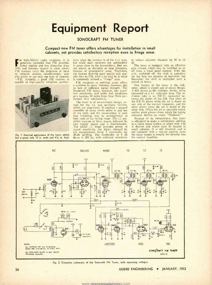
Equipment Report SONOCRAFT FM TUNER
Compact new FM tuner offers advantages for installation in small cabinets, yet provides satisfactory reception even in fringe areas.
FOR high -fidelity radio reception, it is generally conceded that FM provides better quality and less distortion than
AM, and listeners located in cities where FM stations carry the programs of local or network stations simultaneously usu- ally prefer to use only one type of receiver -FM. Actually, a good AM receiver is capable f Huh-quality reception, particu-
Fig. 1. External appearance of the tuner, which has a panel only 10 -in. wide and 41/4 in. high.
larly when the receiver is of the t.r.f. type, but while such receivers are satisfactory in areas close to the transmitters, they are not nearly so desirable at long distances, because of atmospheric noise. Therefore, the listener desiring good quality will usu- ally turn to FM, even if he may be in what is commonly termed a "fringe" area.
FM reception in outlying areas offers a problem to many listeners, however, due to lack of sufficient signal strength. The Sonocraft FM tuner, however, has excel- lent sensitivity, and under test conditions at a location 40 miles from New York per- formed very satisfactorily.
The tuner is of conventional design, ex- cept for the r.f. and oscillator circuits, which are slug -tuned. It employs a ganged assembly of cores which move in and out of the coils, and the construction is such that trimming may be accomplished at both ends of the tuning range. The i.f. am- plifier consists of three stages, followed by two limiter stages and a discriminator. The 6AG5 r.f. stage provides plenty of signal sensitivity, the figure claimed by the manufacturer being 5 microvolts for 20 -db quieting. The bandwidth at 6 db d11wn i. 0n kc, with sufficient .electivity
to reduce adjacent channels by 50 to 60 db.
The tuner is equipped with an effective a.f.c. circuit, which may be switched on or off from a front panel control. With the a.f.c. switched off, the drift is excessive for the first ten minutes of operation, but thereafter the drift is negligible over a period of hours.
One feature of the turner is the indi- cator, which is simple and of clever design. A 6J6 serves as the indicator driver, being connected as a v.t. voltmeter tube. The in- creator tube is an NE -51. connected be- tween the plates of the 6J6. One plate of the NE -5I glows when the set is tuned on one side of the correct frequency, and the other glows when the set is tuned to the other side. When the set is correctly tuned, neither plate glows -from which the tuning indicator derives its name, "Blackout."
Because of its compactness, this tuner is adjudged to make a satisfactory addition to a home music system in which only FM is desired and which must be housed in small cabinets. It is self powered, and is not equipped with a volume control, since the tuner output is usually fed directly into the control amplifier.
o ANT
MON o
,1G
R-F
-a-- PUS[
117 N. M
Eo+
OSC-AFC
i 500
75
MIXER I_F
t aMF
20
6J6
Y
o
50 N AA
66E6 .,,
I-F I-F
ne
q.T MC
10 MEG
DI
- Tl E E.
44 DIAL LIGHTS
ALL HEATERS
250 115
6x4
NOTE, ALL VOLTAGES AVE D C TO CHASSIS, Top00 pet vOLT /METER. NO SIGNAL INPUT.
ALL CAPACITANCE VALUES IN MMF UNLESS
OTHERWISE INDICATED
4000
10 Si
,M 100
50-50 MF
-r 350/500 V.
a
A- T5
có
40 rso.
LIMITERS
L n.
-J
100 It 5
SO
p
NE-5r
u
E50
ow
LIME
?OUTPUT 500
DISC IND.
6J6
SANG rAFT FM TUNER
ASC -2
56
Fig. 2. Complete schematic of the Sonocraft FM Tuner, with operating voltages.
AUDIO ENGINEERING JANUARY, 1953
www.americanradiohistory.comAmericanRadioHistory.Com
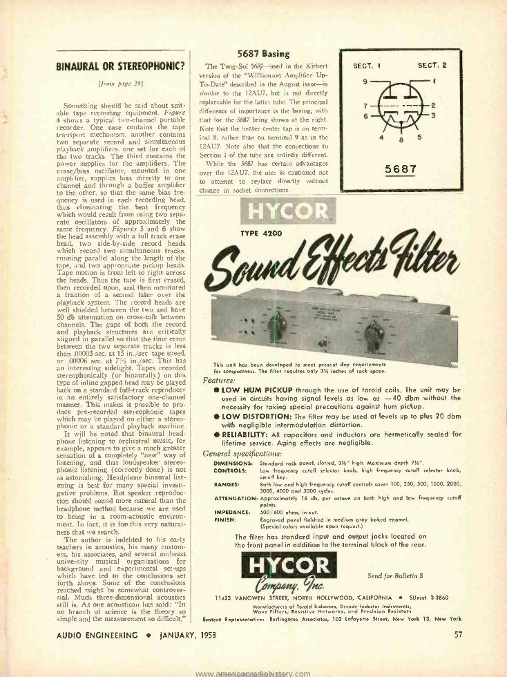
BINAURAL OR STEREOPHONIC?
[from page 24]
Something should be said about suit- able tape recording equipment. Figure 4 shows a typical two- channel portable recorder. One case contains the tape transport mechanism. another contains two separate record and simultaneous playback amplifiers. one set for each of the two tracks. The third contains the power supplies for the amplifiers. The erase/bias oscillator, mounted in one amplifier, supplies bias directly to one channel and through a buffer amplifier to the other, so that the same bias fre- quency is used in each recording head, thus eliminating the beat frequency which would result from using two sepa- rate oscillators of approximately the same frequency. Figures 5 and 6 show the head assembly with a full track erase head, two side -by -side record heads which record two simultaneous tracks. running parallel along the length of the tape. and two appropriate pickup heads. Tape motion is from left to right across the heads. Thus the tape is first erased, then recorded upon, and then monitored a fraction of a second later over the playback system. The record heads are well shielded between the two and have 50 db attenuation on cross -talk between channels. The gaps of both the record and playback structures are critically aligned in parallel so that the time error between the two separate tracks is less than .00003 sec. at 15 in. /sec. tape speed, or .00006 sec. at 7% in. /sec. This has an interesting sidelight. Tapes recorded stereophonically (or binaurally) on this type of inline gapped head may be played back on a standard full -track repìoducer in an entirely satisfactory one -channel manner. This makes it possible to pro- duce pre- recorded stereophonic tapes which may be played on either a stereo- phonic or a standard playback machine.
It will be noted that binaural head- phone listening to orchestral music, for example, appears to give a much greater sensation of a completely "new" way of listening, and that loudspeaker stereo- phonic listening (correctly done) is not as astonishing. Headphone binaural list- ening is best for many special investi- gative problems. But speaker reproduc- tion should sound more natural than the headphone method because we are used to being in a room -acoustic environ- ment. In fact, it is for this very natural- ness that we search.
The author is indebted to his early teachers in acoustics, his many custom- ers, his associates, and several midwest university musical organizations for background and experimental set -ups which have led to the conclusions set forth above. Some of the conclusions reached might be somewhat controver- sial. Much three- dimensional acoustics still is. As one acoustican has said: "In no branch of science is the theory so simple and the measurement so difficult."
5687 Basing The Tung -Sol 5687 -used in the Kiebert
version of the "Williamson Amplifier Up To -Date" described in the August issue -is similar to the 12AU7, but is not directly replaceable for the latter tube. The principal -
difference of importance is the basing, with that for the 5687 being shown at the right. Note that the heater center tap is on term- inal 8, rather than on terminal 9 as in the 12AU7. Note also that the connections to Section 1 of the tube are entirely different.
While the 5687 has certain advantages over the 12AU7, the user is cautioned not to attempt to replace directly without change in socket connections.
TYPE 42C0
I
This unit hos been developed to meet present day requirements for compactness. The filter requires only 31/2 inches of rock space.
Features: LOW HUM PICKUP through the use of toroid coils. The unit may be used in circuits having signal levels as low as -40 dbm without the necessity for taking special precautions against hum pickup. LOW DISTORTION: The filter may be used at levels up to plus 20 dbm with negligible intermodulation distortion. RELIABILITY: All capacitors and inductors are hermetically sealed for lifetime service. Aging effects are negligible.
General specifications: DIMENSIONS: Standard rack panel, slotted, 31/2" high. Maximum depth 71/2'.
CONTROLS: Low frequency cutoff selector knob, high frequency cutoff selector knob, on-o4 key.
RANGES: Both low and high frequency cutoff controls cover 100, 250, 500, 1000, 2000, 3000, 4000 and 5000 cycles.
ATTENUATION: Approximately 16 db, per octave on both high and low frequency cutoff points. 500;'600 ohms, in -out.
Engraved panel finished in medium gray baked enamel. (Special colors available upon request.)
The filter has standard input and output jacks located on the front panel in addition to the terminal block at the rear.
IMPEDANCE: PUNISH:
Send for Bulletin S
11423 VANOWEN STREET, NORTH HOLLYWOOD, CALIFORNIA SUnset 3 -3860
Manufacturers of Toroid Inductors, Decade Inductor Instruments, Wave Filters, Resistive Networks, and Precision Resistors
Eastern Representative: Burlingame Associates, 103 Lafayette Street, New York 13, New York
AUDIO ENGINEERING JANUARY, 1953 57
www.americanradiohistory.comAmericanRadioHistory.Com
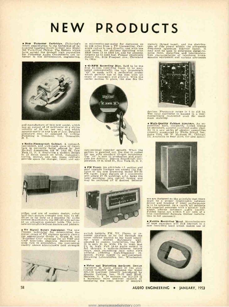
NEW PRODUCTS New Turnover Cartridge. Pickering's
latest contribution to the technique of re- creating recorded music is their new Model 260 Turn -Over Pickup. The factors which have earned the present high reputation for Pickering Audio Components are in- herent in the development, engineering,
and manufacture of this new model, which has an output of 30 millivolts at a stylus velocity of 10 cm. per sec., and which mounts easily In any type of arm. Detailed literature may be obtained by writing Pickering & Company, Inc., Oceanside, N. Y.
Radio- Phonograph Cabinet. A compact, convenient, and well -made piece of furni- ture is currently being offered by Jett Markel' Associates, 108 W. 14th St. New York 11, N. Y. Featuring a modern design in 12 finish colore on birch, mahogany, korina, walnut, and oak, these cabinets provide space for changer, tuner, and am-
in microvolts- per -meter for distances up to 100 miles from a TV transmitter. Cov- erage radius is read directly, and with one rule setting, for stations operating with ERP from 10 to 1000 kw and for antenna heights up to 3000 feet. Pioneer Electronic Supply Co., 2115 Prospect Ave., Cleveland 15, Ohio.
45-RPW Recording Disc. Said to be the first 45 -rpm recording blank to be mar- keted commercially, the new Soundcraft "45" is made with a perforated center which permits use of the disc with all types of recorders and players. With the center section in place, the disc fits the
conventional recorder spindle. When the section is punched out, the disc is suited for use with standard 45 -rpm turntables. The "45" is now in production and avail- able for delivery. Reeves Soundcraft Cor- poration, 10 E. 52nd St., New York 22, N. Y.
Pig Tuner. An all -triode r.f. section and dual cascade limiters are among the fea- tures of the new Browning Model RV -31 FM tuner. Input signals of 3 microvolts will afford 20 db quieting; a.f.c. locks the local oscillator into correct tuning and may be switched off if desired. Selector
glider, and are of modern design, using half -inch square wrought iron legs. In ad- dition to its duty as a housing for audio system components, the RC -118 also serves as an attractive cocktail table. The cabi- nets are available from dealers and jobbers.
TV Signal Range Calculator. The new Pioneer calculator for determining the signal range of TV stations quickly shows the approximate Grade A, Grade B, and "Principal City" coverage for all VHF and UHF television channels. Resembling a slide rule in appearance, the instrument readily shows approximate field strength
58
switch permits FM, TV Phono, or re- corder playback to be fed through the tuner volume control to the basic ampli- fier when desired. Extremely well -
adapted to custom installation, the RV- 31 is only 11 in. wide, 9% in. deep, and 6 in. high. Full 15 -kc audio output is fed through a cathode -follower output stage, thus permitting long cable runs without affecting high- frequency re- sponse. Power supply is self- contained. Browning Laboratories, Inc., Winchester, Mass.
Noise and Distortion Analyser. Design engineers in many phases of the elec- tronics industry will welcome the Model ND -110 analyzer recently introduced by Empire Devices Inc., 38 -25 Bell Blvd., Bayside, N. Y. In essence the ND -110 is a harmonic wave analyzer capable of measuring the mean power of complex
signals (broad band) and the distribu- tion of this power within the ultrasonic frequency spectrum (narrow band). It may also be used to determine signal -to- noise ratio, distortion and intermodula- tion characteristics of telephone trans- mission golpment and cri rinuv ultrasonic
devices. Frequency range is 4 to 110 kc. The local oscillator is housed in a ther- mostatically controlled oven for maxi- mum stability.
Sigh-Quality Cabinet Speakers. An ex- ponential horn, compactly folded within an enclosure, assures excellent audio qual- ity in a new series of speaker assemblies recently announced by White Sound, Inc., Suite 1105 105 W. Madison St., Chicago, Ill. Available in four sizes, the new speak-
ers are designed on the princip, that there must be a proper relationship between driver and housing if ideal performance is to be achieved. As a result, all cabinets are supplied complete with a speaker unit which affords optimum audio quality. Folded horns are within 2 per cent of a true exponential formula. Corner installa- tion is not necessary.
Ferrite Recording Read. Manufacturers of tape recorders will find interest in a new recording head which makes use of
AUDIO ENGINEERING JANUARY. 1953
www.americanradiohistory.comAmericanRadioHistory.Com
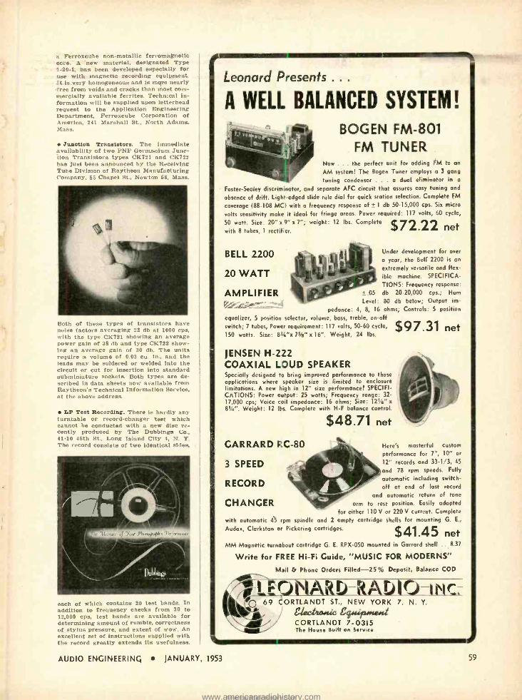
a Ferroxcube non -metallic ferromagnetic core. A 'new material, designated Type 1,20-1, has been developed especially for use with magnetic recording equipment. It is very homogeneous and is more nearly free from voids and cracks than most com- mercially available ferrites. Technical in- formation will be supplied upon letterhead request to the Application Engineering Department, Ferroxcube Corporation of America, 241 Marshall St., North Adams, Mass.
Junction Transistors. The immediate availability of two PNP Germanium Junc- tion Transistors types CK721 and CK722 has just been announced by the Receiving Tube Division of Raytheon Manufacturing Company, 56 Chapel St., Newton 58, Mass.
Both of these types of transistors have noise factors averaging 22 db at 1000 cps, with the type CK721 showing an average power gain of 38 db and type CK722 show- ing an average gain of 30 db. The units require a volume of 0.03 cu. in., and the leads may be soldered or welded into the circuit or cut for insertion into standard subminiature sockets. Both types are de- scribed in data sheets now available from Raytheon's Technical Information Service, at the above address.
LP Test Recording. There is hardly any turntable or record- changer test which cannot be conducted with a new disc re- cently produced by The Dubbings Co., 91 -10 45th St., Long Island City 4, N. Y. The record consiste of two identical sides,
each of which contains 20 test bands. In addition to frequency checks from 80 to 12,000 cps, test bands are available for determining amount of rumble, correctness of stylus pressure, and extent of wow. An excellent set of instructions supplied with the record greatly extends its usefulness.
Leonard Presents . . .
A WELL BALANCED SYSTEM!
BOGEN FM -801 FM TUNER
Now ... the perfect unit for adding FM to an
AM system! The Bogen Tuner employs a 3 gang
tuning condenser . . . a dual eliminator in a
Foster -Seeley discriminator, and separate AFC circuit that assures easy tuning and
absence of drift. Light -edged slide rule dial for quick station selection. Complete FM
coverage (88 -108 MCI with a frequency response of ± 1 db 50- 15,000 cps. Six micro
volts sensitivity make it ideal for fringe areas. Power required: 117 volts, 60 cycle,
50 watt. Size: 20" x 9" x 7 "; weight: 12 lbs. Complete $ 72 22 with 8 tubes, 1 rectifier. net
BELL 2200
20 WATT
AMPLIFIER
Under development for over
a year, the Bell 2200 is an
extremely versatile and flex- ible machine. SPECIFICA- TIONS: Frequency response:
.05 db 20- 20,000 cps.; Hum
Level: 80 db below; Output im-
pedance: 4, 8, 16 ohms; Controls: 5 position
equalizer, 5 position selector, volume, bass, treble, on -off switch; 7 tubes, Power requirement: 117 volts, 50 -60 cycle,
150 watts. Size: 81/4"x 7s's" x 16 ". Weight, 24 lbs.
JENSEN H -222 COAXIAL LOUD SPEAKER Specially designed to bring improved performance to those applications where speaker size is limited to enclosure limitations. A new high in 12" size performance! SPECIFI- CATIONS: Power output: 25 watts; Frequency range: 32- 17,000 cps; Voice coil impedance: 16 ohms; Size: 121/a" x
81/4". Weight: 12 lbs. Complete with H -F balance control.
$48.71 net
$97.31 net
GARRARD î :C -80 Herés masterful custom
performance for 7 ", 10" or
12" records and 33.1/3, 45
and 78 rpm speeds. Fully
automatic including switch -
off at end of lost record
and automatic return of tone
arm to rest position. Easily adapted
for either 110 V or 220 V current. Complete
with automatic 45 rpm spindle and 2 empty cartridge shells for mounting G. E.,
Audax, Clarkston or Pickering cartridges.
3 SPEED
RECORD
CHANGER
.
$41.45 net MM Magnetic turnabout cartridge G. E. RPX -050 mounted in Garrard shell .. 8.37
Write for FREE Hi -Fi Cuide, "MUSIC FOR MODERNS"
Mail G Phone Orders Filled -25% Deposit, Balance COD ! fit kl) -kr D 0 -I I C-, G69 CORTLANDT ST., NEW YORK 7, N. Y.
, II e%cfico is 4441124rge4 CORTLANDT 7 -0315 The House Built on Service
AUDIO ENGINEERING JANUARY, 1953 5g
www.americanradiohistory.comAmericanRadioHistory.Com
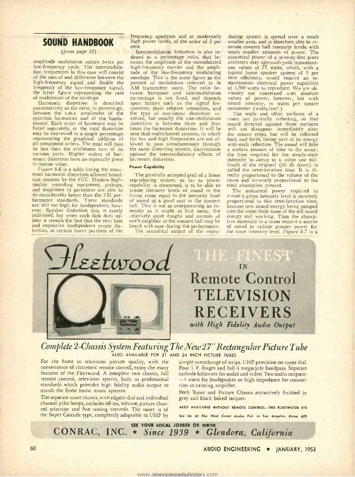
SOUNb HANDBOOK (from page 32)
amplitude modulation occurs twice per low- frequency cycle. The intermodula- tion frequencies in this case will consist of the sum of and difference between the high -frequency signal and double the frequency of the low- frequency signal, the latter figure representing the rate of modulation of the envelope.
Harmonic distortion is described quantitatively as the ratio, in percentage, between the r.m.s. amplitudes of the spurious harmonics and of the funda- mental. Each order of harmonic may be listed separately, or the total distortion may be expressed in a single percentage representing the graphical addition of all component orders. The total will thus be less than the arithmetic sum of its various parts. Higher orders of har- monic distortion have an especially great irritation value.
Figure 8 -6 is a table listing the maxi- mum harmonic distortion allowed broad- cast stations by the FCC. Modern high - quality recording equipment, pickups, and amplifiers in particular are able to do considerably better than the FM per- formance standards. These standards are still too high for loudspeakers, how- ever. Speaker distortion data is rarely published, but when such data does ap- pear it reveals the fact that the very best and expensive loudspeakers create dis- tortion, at certain lower portions of the
frequency spectrum and at moderately high power levels, of the order of 5 per cent.
Intermodulation distortion is also in- dexed as a percentage ratio, that be- tween the amplitude of the unmodulated high -frequency carrier and the ampli- tude of the low- frequency modulating envelope. This is the same figure as the percent of modulation referred to in AM transmitter work. The ratio be- tween harmonic and intermodulation percentage is not fixed, and depends upon factors such as the signal fre- quencies, their relative intensities, and the type of non -linear distortion in- volved, but usually the intermodulation distortion is between three and four times the harmonic distortion. It will be seen that multichannel systems, in which the low and high frequencies are not al- lowed to pass simultaneously through the same distorting system, discriminate against the intermodulatooy effects of harmonic distortion.
Power Capability
The generally accepted goal of a home reproducing system, as far as power capability is concerned, is to be able to create intensity levels of sound in the living room equal to the intensity level of sound at a good seat in the concert hall. This is not as overpowering an in- tensity as it might at first seem; the relatively quiet coughs and sneezes of one's neighbor at the concert hall may be heard with ease during the performance.
The acoustical output of the repro-
ducing system is spread over a much smaller area, and is therefore able to re- create concert hall intensity levels with much smaller amounts of power. The acoustical power of a seventy -five piece orchestra may approach peak instantane- ous values of 75 watts, which, with a typical home speaker system of 5 per cent efficiency, would require an in- stantaneous electrical power capability of 1,500 watts to reproduce. We are ob- viously not concerned with absolute values of power, however, btu with sound intensity, in watts per square centimeter (watts /cm2.)
The walls and other surfaces of a room are partially reflecting, so that sound directed against these surfaces will not disappear immediately after the source stops, but will be reflected back and forth, losing part of its energy with each reflection. The sound will take a certain amount of time to die away; the time required for the steady -state intensity to .decay to a value one mil- lionth of the original (60 db down) is called the reverberation tinge. It is di- rectly proportional to the volume of the room and inversely proportional to the total absorption present.
The acoustical power required to create a given intensity level is inversely proportional to this reverberation time, because new sound energy being pumped into the room finds some of the old sound energy still working. Thus the absorp- tive materials in a room require a source of sound to radiate greater power for the same intensity level. Figure 8 -7 is a
9fEEtwood
60
Complete 2- Chassis System Featuring ALSO AVAILABLE FOR 21
For the finest in television picture quality, with the convenience of electronic remote control, enjoy the many features of the Fleetwood. A complete two chassis, full remote control, television system, built to professional standards which provides high fidelity audio output to match the finest home music systems. The separate tuner chassis, with edgelit dial and individual channel pilot lamps, includes off -on, volume, picture chan- nel selection and fine tuning controls. The tuner is of the Super Cascode type, completely adaptable to UHF by
Remote Control TELEVISION RECEIVERS
with High Fidelity Audio Output
The New 27" Rectangular Picture Tube AND 24 INCH PICTURE TUBES
simple interchange of strips. UHF provision on tuner diaL Four I. F. Stages and full 4 megacycle bandpass. Separate cathode followers for audio and video. Two audio outputs: -4 watts for loudspeaker or high impedance for connec- tion to existing amplifier. Both Tuner and Picture Chassis attractively finished in gray and black baked lacquer.
ALSO AVAILABLE WITHOUT REMOTE CONTROL -THE FLEETWOOD 610
See Us At The Weal Coast Audio Fair in Los Angeles, Room 623
SEE YOUR LOCAL JOBBER OR WRITE
CONRAC, INC. * Since 1939 * Glendora,
AUDIO ENGINEERING JANUARY, 1953
www.americanradiohistory.comAmericanRadioHistory.Com
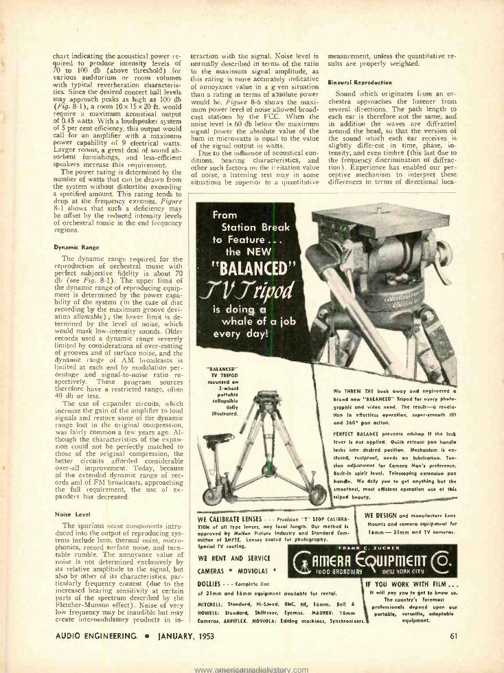
chart indicating the acoustical power re- quired to produce intensity levels of 70 to 100 db (above threshold) for various auditorium or room volumes with typical reverberation characteris- tics. Since the desired concert hall levels may approach peaks as high as 100 db (Fig. 8 -1), a room 10 x 15 x 20 ft. would require a maximum acoustical output of 0.45 watts. With a loudspeaker system of 5 per cent efficiency, this output would call for an amplifier with a maximum power capability of 9 electrical watts. Larger rooms, a great deal of sound ab- sorbent furnishings, and less -efficient speakers increase this requirement.
The power rating is determined by the number of watts that can be drawn from the system without distortion exceeding a specified amount. This rating tends to drop at the frequency exremes. Figure 8 -1 shows that such a deficiency may be offset by the reduced intensity levels of orchestral music in the end frequency regions.
Dynamic Range
The dynamic range required for the reproduction of orchestral music with perfect subjective fidelity is about 70 db (see Fig. 8 -1). The upper limit of the dynamic range of reproducing equip- ment is determined by the power capa- bility of the system (in the case of disc recording by the maximum groove devi- ation allowable) ; the lower limit is de- termined by the level of noise, which would mask low- intensity sounds. Older records used a dynamic range severely limited by considerations of over -cutting of grooves and of surface noise, and the dynamic range of AM broadcasts is limited at each end by modulation per- centage and signal -to -noise ratio re- spectively. These program sources therefore have a restricted range, often 40 db or less.
The use of expander circuits, which increase the gain of the amplifier to loud signals and restore some of the dynamic range lost in the original compression, was fairly common a few years ago. Al- though the characteristics of the expan- sion could not be perfectly matched to those of the original compression, the better circuits afforded considerable over -all improvement. Today, because of the extended dynamic range of rec- ords and of FM broadcasts, approaching the full requirement, the use of ex- panders has decreased.
Noise Level
The spurious noise components intro- duced into the output of reproducing sys- tems include hum, thermal noise, micro - phonics, record surface noise, and turn- table rumble. The annoyance value of noise is not determined exclusively by its relative amplitude to the signal, but also by other of its characteristics, par- ticularly frequency content (due to the increased hearing sensitivity at certain parts of the spectrum described by the Fletcher- Munson effect). Noise of very low frequency may be inaudible but may create intermodulatory products in in-
teraction with the signal. Noise level is normally described in terms of the ratio to the maximum signal amplitude, as this rating is more accurately indicative of annoyance value in a g ven situation than a rating in terms of absolute power would be. Figure 8-6 shows the maxi- mum power level of noise allowed broad- cast stations by the FCC. When the noise level is 60 db below the maximum signal power the absolute value of the hum in microwatts is equal to the value of the signal output in watts.
Due to the influence of acoustical con- ditions, hearing characteristics, and other such factors o11 the i- ritation value of noise, a listening test may in some situations be superior to a quantitative
measurement, unless the quantitative re- sults are properly weighted.
Binaural Reproduction
Sound which originates from an or- chestra approaches the listener from several directions. The path length to each ear is therefore not the same, and in addition the waves are diffracted around the head, so that the version of the sound which each ear receives is slightly different in time, phase, in- tensity, and even timbre (this last due to the frequency discrimination of diffrac- tion). Experience has enabled our per- ceptive mechanism to interpret these differences in terms of directional loca-
From Station Break
to Feature... the NEW
t.
"BALANCED" i Yirivod is doing a
whale of a job every day!
r::s.
"BALANCED" TV TRIPOD
mounted on 3 -wheel portable
collapsible dolly
illustrated.
We THREW THE book away and engineered a
brand new "BALANCED" Tripod for every photo-
graphic and video need. The result-a revela-
tion in effortless operation, super -smooth tilt and 360° pan action.
PERFECT BALANCE prevents mishap if the lock
lever is not applied. Quick release pan handle
locks into desired position. Mechanism is en-
closed, rustproof, needs no lubrication. Ten-
sion adjustment for Camera Man's preference.
Built -in spirit level. Telescoping extension pan
handle. We defy you to get anything but the
smoothest, most efficient operation out of this
tripod beauty.
WE CALIBRATE LENSES Precision "T" STOP CALIBRA-
TION of all type lenses, any focal length. Our method k approved by Motion Picture Industry and Standard Com-
mittee of SMPTE. Lenses c sated for photography. Special TV coating.
WE RENT AND SERVICE
CAMERAS MOVIOLAS
DOLLIES Complete line
of 35mm and 16mm equif ment available for rental.
MITCHELL: Standard, Hi -S seed, BNC, NC, 16mm. Bell
WE DESIGN and manufacture Lens
Mounts and camera equipment for
16mm - 35mm and TV cameras.
FRANK C. ZUCKER
GAMERA EQUIPmEf1TC. 1600 BROADWAY f1EW YORK CITY
HOWELL: Standard, Shift sver, Eyemos. MAURER:
8
16mm
Cameras. ARRIFLEX. MOVIOLA: Editing machines, Synchronisers.
AUDIO ENGINEERING JANUARY, 1953
IF YOU WORK WITH FILM .. .
It will pay you to get to know us.
The country's foremost professionals depend upon our portable, versatile, adaptable
equipment.
61
www.americanradiohistory.comAmericanRadioHistory.Com
At your age! If you are over 21 (or under 101) it's none too soon for you to follow the example of our hero, Ed Parmalee (above) and face the life- saving facts about cancer, as presented in ,
our new film "Man Alive! ". You and Ed will learn that
cancer, like serious engine trouble, usually gives you a warning and can usually be cured if treated early.
For information on where you can see this film, call us or write to "Cancer" in care of your local Post Office.
American Cancer Society
tion of the source or sources. Monaural reproduction from a single reproducing source eliminates this factor of realism, and has a definite effect on the illusion created, although there may be differ- ences of opinion on the importance of the musical values associated with the loss.
The lost illusion may be restored, to a greater or lesser degree depending upon the method used, by stereophonic or binaural reproduction. A practical binaural system that is perfect can only work through earphones. Two record- ing microphones are mounted as though each were one human ear ; the sound received by each is recorded separately, and each recorded channel is played back into its corresponding left or right ear- piece. In this way each ear re- ceives a version of the music with just those characteristics that the left or right -side version would have contained in the concert hall.
Since earphones are much less con- venient than loudspeakers, most prac- tical stereophonic systems are designed for speakers. Each channel no longer represents the sound received by each ear, but the sound coming from the left or the right of the hall, all of which is received by both ears. This arrange- ment, for accuracy of stereophonic effect, would require many channels and a careful arrangement of the speaker array calibrated to the original layout of instruments. Such a procedure is ob- viously impractical except for the thea-
ter, and typical stereophonic systems use two channels and two permanently mounted loudspeakers. The results are a compromise but nevertheless afford an appreciable increase in "liveness."
Binaural demonstrations with ear- phones are always much more dramatic than those with louspeakers. The reason for the greater illusion is described above, but there is another factor that increases the contrast between the monaural and binaural sound. Single - channel reproduction through earphones creates an artificial and impossible acoustical condition; each ear receives the identical sound at the same instant. Because of the fact that the normal left - right differences associated with diffrac- tion around the head and reflection from room surfaces are eliminated when the ears are covered, such reproduction is unusually "flat ", even when compared to that of a single loudspeaker. The con- trast is thus widened by a particularly weak monaural standard.
GO WEST! Its the West Coast
AUDIO FAIR Feb, 5, 6, 7
Alexandria Hotel
Los Angeles, California
ORDER NOW !
1952 Bound Volumes -$8.95 (Outside U.S.A. add 75 cents postage)
Over the years, AUDIO ENGINEERING has proven itself a valuable reference work worthy of a permanent place in your library. Many 1952 issues are already exhausted but you may have a
complete bound volume of new copies for the entire year if you order now.
For the years to come - Subscribe to AUDIO ENGINEERING on the combination offer which includes a bound volume at the end of the year. Each
month you receive the magazine by mail as usual -read it,
cut out coupons to your heart's content, mark on the pages
as much as you like. Around January 15, 1954, you receive a
fresh, new, bound volume of 1953 issues -no creases, no
dog -eared pages. The cost?- only $10.00 per year, a saving
of $1.95 over the price of the bound volume and the one -year
subscription. Same offer, for two years, $18.50.
(Canada and Pan -American Union -1 yr. $11.00, 2 yrs. $20.00; all other foreign -1 yr. $12.00, 2 yrs. $22.00)
Dept SV,
AUDIO ENGINEERING,
P. O. Box 629, Mineola, N. Y.
This offer expires
February 1, 1953
Enclosed is my check for money order) for $ for .... copies of the 1952 Bound Volume of AUDIO ENGINEERING,
to be delivered about January 15, 1953.
Enclosed is my check (or money order) for $ for a new renewal subscription for one year, plus a 1953
Bound Volume which will be delivered without further charges approximately January 15, 1954.
Enclosed is my check (or money order) for $ for a new renewal subscription for two years, plus a 1953
Bound Volume which will be delivered without further charges approximately January 15, 1954, and plus a 1954 Bound Volume to be delivered about January 15, 1955.
Name
4ddress
City .... Zone .... State
62 AUDIO ENGINEERING JANUARY, 1953
www.americanradiohistory.comAmericanRadioHistory.Com
NEW LITERATURE Engineering Products Department, RCA
Victor Division, Camden 2, N. J. has pro- duced a full -color sound film titled "You Are the Producer," which demonstrates and explains how educators, industrial training groups, home movie makers, etc., can record their own sound on l6 -mm film at nominal expense and without labora- tory processing. The ,12- minute film fea- tures the RCA "400" magnetic recorder - projector in an interesting dramatic sequence based on the ability of the unit to record on magnetic track, play back, erase, reproduce both optical and magnetic track, and operate at sound or silent speed. Information concerning use of the film for showing before interested groups may be obtained from any RCA visual products distributor, or by mailing an inquiry to the address shown above.
Thordarsoa -7g issa r, Mt. Carmel, Ill., is now distributing the company's new gen- eral catalog No. 53 -A, a complete listing of all items manufactured under the Meissner trade mark. Many new products are shown for the first time, including a 10 -watt high - fidelity amplifier and a transmitter kit for novices. A special section is devoted to re- ceiver and amplifier kits. Copy will be mailed free for the asking.
Osn ral Electric Company, Tube Depart- ment, 1 River Road Schenectady 5 N. Y., announces availability of a new booklet describing the essential characteristics of G -E Five Star miniature and subminiature high -reliability tubes. Included in the data are the specific differences between Indi- vidual Five Star tubes and their standard - tube counterparts. When writing specify Publication ETD -548 -A.
ElOIatosh Laboratory, Inc., 320 Water St., Binghamton, N. Y., will mail free a new 32 -page booklet titled "Lost Instru- ments," which makes use of cartoons to explain the whys and wherefores of high - quality audio equipment. Shown graphi- cally are the meanings of such technical terms as intermodulation, harmonic dis- tortion, band width etc. An informative publication for both beginners and vet- erans in the audio field. Write for it.
dustier -Bacon W .aantaatnrliag Co., 210 W. 10th St., Kansas City, Mo., is introduc- ing Ultrafine, a new thermal and acousti- cal insulation with a handsome 4 -page folder which includes illustrations of the product in use, as well as tables listing thermal and acoustical efficiency. Ultrafine is made' of extremely fine, blown glass fibres, and can be obtained in a variety of facings.
Automatic Electric Co., 1033 W. Van Buren St., Chicago 7, III., describes and illustrates a complete line of telephone - type relays including hermetically -sealed subminiature and plug -in types, in a color- ful new 12 -page brochure designated as Circular 1702 -A. This is one of the finer examples of industrial publishing to cross this desk In many moons. If you use small relays, you will find a copy of great value.
Lo,yrt 149444
POSITIONS OPEN and AVAILABLE PERSONNEL may be listed here at no charge to industry or to members of the Society. For insertion in this col- umn, brief announcements should be in the hands of the Secretary, Audio En- gineering Society, P. O. Box 12, Old Chelsea Station, N. Y. 11, N. Y., before the fifth of the month preceding the date of issue. 'k Position Open Positions Wanted * Audio Systems Engineer. Opportunity in new Audio Systems Section to create new products in professional and repro- ducing equipment. Telephone Mr. Mar- shall. INdependence 3 -2100 days, FLoral Park 2 -0578 evenings. Fairchild Record- ing Equipment Corporation, 7th Avenue and Powell's Cove Road, Whitestone,
You are cordially invited to attend the first 1953
ß[U10 FAIR LOS ANGELES
Sponsored by the AUDIO ENGINEERING SOCIETY in conjunction with its Los Angeles Section Technical Sessions
HIGH FIDELITY audio equipment and home music components to be demonstrated and displayed for lovers of high- gLality reproduction, audio- philes, sound enthjsiasts, recordists, FM -AM -TV electronic engineers, dis- tributors, dealers and technicians.
YOU WILL SEE -HEAR -ENJOY the largest a +d most concentrated ex- hibition of audio equipment under one roof -featuring the latest products and newest develo)ments of more than 75 nationally known manufacturers.
ADMISSION FREE TO ALL EXHIBITS
For further information, w'ite
William L. Cara, Fair Manager 4245 Normal Ave., Los Angeles 29, Calif.
Richmond 7 -3196 OLympia 4988
AUDIO GEN. KIT
$29só
R. F. SIGNAL o GEN. KIT
6 $195ó ls % I.
-J ¡I SCOPE KIT
$435°'L R BUILD YOUR OWN
T.V. ALIGN. GEN. KIT
$39515
'e dkr 'TEST EQUIPMENT
ìío dd,oare.,nnpkniy cngh, red ho
strumcna supplied unassembled. Every
kit goes together smoothly and easily.
All drilling, punching. and painting has
already been dove for you. All parts are
furnished and are of highest quality.
Detailed construction manual shows
dearly where each wire and part goes
ant tells exactly how to build the kir. Write for free catalog.
SIGNAL TRACER KIT
$225°
BATTERY ELIMINATOR
KIT
$2450
VACUUM TUBE VOLTMETER KIT
$24? HEATH COMPANY
IMPEDANCE BRIDGE Kl1 s695ó
BENTON HARBOR 12 MICHIGAN
EXPORT AGENT
ROCKE INTERNATIONAL CORP. 13 Eon AO. Ease,
NEW YORK CITY ('6) TUBE CHECKER
KIT
52950 CONDENSER
CHECKER KI
$19só GR. D DIP METER 81950 KET
AUDIO ENGINEERING JANUARY, 1953 63
www.americanradiohistory.comAmericanRadioHistory.Com
Attenuators Precision
and General Purpose, "T" Type
Both with impedance range from 30 to 600 ohms. Pre- cision resistors held to within
1% accuracy . . general purpose within 5%. Also Bal. H types.
Range Extending For use with all makes of V.U.
and D.B. meters. All resistors within t 1 %.
Potentiometers Precision and General Purpose grid control types with non -inductive, wirewound resistors. Also dual precision wirewound grid potentiometers.
Write for Complete Catalog N. Y. Steh:
Audio & Video Products Corp.. 730 fifth Are, Flosa 74091
CINEMA ENGINEERING COMPANY L.T3 WES: V(RUUOO AVENUE RURSN CALIFORNIA
Expert Aonts: fresar & H , Ltd.. 301 Clay SI Son Francisco, Calif.U.S.A.
Model 3422 1518,000 cps.
WHITE SOUND GIVES YOU THE
Ultimate in. Instrumentation ?raid WHITE CABINET SPEAKERS
A True Exponential Horn ... ( within 1%), Coupled to Speaker through a New Unique
e. Phasing Device and Sound Trap Nine foot Horn compactly Curled into Non -Resonant Cabinet Response: 15- 18,000 cps Virtual
. Distortion Free Reproduction of Low Fre- quencies Flowing Peakless Sound without Resonance - Blonde Korina or Mahogany
Hand Rubbed Finish Bonded Formica Top Size 351H- 23W -20D.
Model 3422 FOB $595.00 White Cabinet Speakers offered in 4 Sizes ...3 Finishes...5 Prices.
... Ultra High Fidelity ... {rein WHITE SOUND AMPLIFIERS Cross -Coupled Amplifier Circuitry Balanced Drive Tapped Screen Output Balanced Impedence Phase Inverter
Eze reslael Non -resonant Cross -Over Circuit Cross -Over (24db./ Octave) at the Input of
Dual Channel Amplifier.
Complete Information, see your Distributor or Write to Department H -11
105 W. MADISON ST. WHITE SOUND, I N C.
CHICAGO 3, ILLINOIS
For
64
FLEXIBLE CHANNEL (front page 29)
because the final product would be on optical film and after making compre- hensive listening tests it was decided that normal optical cut -offs would be useful for magnetic recording also. Due to the increased amount of recording being done, everything is first put on magnetic and then transferred to opti- cal and held until the picture "answer" prints are delivered. In this way the ad- vantage of magnetic is utilized as a safety, as well as for a temporary refer- ence; it is erased after the "all clear" is given. Some time ago, the inventory of magnetic film increased to such an amount- because of the increase of jobs waiting for answer prints -that the sys- tem was later modified and magnetic film is erased and made available for re -use immediately after getting the "go ahead" from the editorial department when they are satisfied they have the proper footage to cover their needs.
As far as the actual operation of the channel is concerned, it was made as straightforward an operating chore as possible so as to eliminate mistakes, floundering for switches, and so on. Therefore, the entire unit is practically left to the Mixer for operation and he has all the switches and patch bays at his fingertips. In operating procedures with the channel, key K, permits the mixer to listen to the signal at the re- cording amplifier buss or to the signal that is actually recorded on the magnetic film. No change in equalization is needed -the Mixer has merely to throw a switch. This is used for all original scoring so that the Mixer himself can be sure that he "has" the take -some jobs not permitting time for a playback. This type of monitoring was not pro- vided in the re- recording operation be- cause of the trouble caused by the time delay. Incidentally, the time delay does not seem to bother the Mixer during direct sound recordings while watching the speaker's lips. It is felt that know- ing the take is on the film and in good shape seems to offset the lack of syn- chronized monitoring. The talkback and monitor amplifiers are used in a con- ventional fashion but are interlocked by key K, so as to eliminate any possi- bilities of feedback while using their circuits. Relay K, is also used as an interlock to prevent the same difficulty when the microphones are "hot" and a playback is needed on the stage. Key Ke is used mainly for playing back any original scoring for checking purposes and automatically sends the signal into the linear and flat channel, thence to the playback amplifier and speaker. This is in line with the wanted design in that the Mixer does all the switching in- volved with the exception of actually rolling the recorders and reproducing equipment. This makes it possible to utilize the services of a relatively inex- perienced recordist without having to keep a constant supervising vigil.
AUDIO ENGINEERING JANUARY, 1953
www.americanradiohistory.comAmericanRadioHistory.Com
r
Motor and Signal Circuits
Referring to Fig. 2 -the schematic showing the motor and signal circuits - it will be seen that there are four "ready light" positions available -two of which are duplicated in the re- recording room. These positions utilize a holding relay that automatically lights a lamp of the proper color at each of the positions. When the machines start to roll, the power is lifted from the circuit and the lights automatically go out. It was origi- nally thought that- because if a ready light was once put on, the operator could not turn it off if he changed his mind -there might be some trouble. However, this took place only in isolated cases, and then only because of unfamili- arity with the system -a condition en- countered occasionally with new or in- experienced personnel. All that is necessary if the operator has to change his signal is for him to use the telephone which is normalled between all sound - interested places. When the units start to roll, the ready lights are released and they go out. In case of trouble, the pro- jection rooms have their own selsyn control, used only for stopping. If the machine room has trouble, the operator makes sure the projection lamp is out - by using the telephone -before stopping. For quick emergencies, the talkback microphone can be used. In addition, each selsyn control box has lights show- ing when it is in a locked position and when rolling so that all interested per- sonnel know exactly what is operating. The "lock" lights are convenient in that they are a signal for the machine men and the projectionist to check their re- spective motors to make sure that they are in lock and not stalled on a "high spot." This completely eliminates the possibility of having a runaway ma- chine. The solenoid that disconnects the ready lights is energized by the selsyn control boxes during dubbing and by a separate push button during original voice or music scorings. The same sole- noid also energizes the warning light system and automatically rings a three - second bell at the start of recording and sounds a three -second buzzer at the end. These unrelated audible signals have been found sufficient to alert any personnel completely while a "take" is on. Provision is also made to control any a.c. machinery needed by means of the same solenoid relay. A rachet -type re- lay was selected so as to draw current only when the contacts are being moved from OFF to ON, or vice versa.
The installation has proved itself time and time again, with very few troubles, to operate in a straightforward and efficient manner in carrying out its sound recording duties, and has come up to the expectations of all concerned.
The author wishes to take this op- portunity to thank everyone who has contributed directly or indirectly in the past five years to his film- recording "education" Particular thanks go to Mr. H. D. Bradbury and his colleagues of RCA Victor Film Recording Division for their helpful advice and assistance.
ONE COMPLETE
DEPENDABLE SOURCE
EOR EVERVTNING
IN ELECTRONICS
We specialize in Electronic Equipment
for Research, Development,
Maintenance and Production Operation
SEND FOR FREE 1953 CATALOG
236 -PAGE
ALLIED 1953
ELECTRONIC SUPPLY
CATALOG
World's Largest Stocks of Electronic Supplies for Industry and Broadcast Stations
Simplify and speed your purchasing of electronic supplies and equipment -send all your orders to ALT1ED
--the reliable one -supply- source for all your electronic needs. Depend c -n ALLIED for the world's largest
' stocks of special- purpose electron tubes, test instruments, a.sdio equipment, electronic Tarts
(transformers, capacitors, controls, etc.) and accessories - complete lines of quality apparatus.
Our expert :neustriel supply service saves you time, effort and money. Send today for your FREE copy o.' the
1953 ALLIED Catalog -the complete, up -to -date guide to the world's largest stocks of Electronic Supplies for
Industrial and Broadcast use.
AUDIO ENGINEERING JANUARY,
ALLIED RADIO CORP. 833 W. Jackson Blvd.,
Dept. 17 -B -3 Chicago 7, Illinais
Custom Styled for Hi- fidelity Designed for the audiophile, these
handsome cabinets will accommodate any combination of high fidelity com- ponents. Panels are replaceable for future changes of equipment. The loud - spesker cabinet is acoustically correct, tunsd for the average 12" or 15" loud - speaker, pre -cut as requested. Construc- tioe is of select birch, with a fine lccquer finish hand- rubbed to a high gloss. All joists are glued and screwed, and lock - joist miters are used throughout, afford- ing utmost rigidity.
Dinensions: 351" high, 231" wide, 18' deep.
Finishes: 31ond Birch :ordovan Mahogany on Birch.
Bogle Area: 61/2 cubic feet.
Net Price
MODEL 27 Loudspeaker
Cabinet
MODEL 27 . . . $48.00
MODEL 28 . . . $72.00
Sold through leading radio parts distributors. Write for free catalog and nearest distributor.
0 0
D000
o I I
G & H WOOD PRODUCTS COMPANY 75 NORTH 11th STREET BROOKLYN 11, N. Y.
Pioneers in radio furniture for high fidelity equipment.
1953 65
www.americanradiohistory.comAmericanRadioHistory.Com
Southern California's Finest Audio Headquarters for the "Famous Modern Classics in Sound" starring the great
Ne L4 eiaasic 25 For UNLIMITED selection of all the stars in sound
Altec Concertone Craftsmen G.E. Jensen Lansing
Pickering Rek -O -Kut
Electro -Voice Fisher Fleetwood Garrard Magnecord McIntosh Newcomb Pederson Scott Stephens University Weathers
A- DIVISION OF FIGARTS RADIO SUPPLY CO. 6320 COMMODORE SLOAT DRIVE LOS ANGELES 48, CALIF. YORK 6218
arid /lau< - The 2nd Audio Antholo
No bigger, no better than the original Audio Anthology -in fact, it's just the same size and a perfect companion to the most authoritative book you now have on the subject of home music systems. But it contains all new mate- rial- reprints of over forty of the valuable ar- ticles which have most interested Æ's readers during the past two and a half years.
Board Cover
Features- Amplifiers
Preamplifiers
Tone Controls
Phonograph Equipment
Loudspeakers
Speaker Enclosures
Tape Recorder Amplifiers
Customary discounts to distributors.
$3.00 Poper Cover
CUT OUT -MAIL TODAY
$2.00
Book Division, Radio Magazines, Inc., P. 0. Box 629, Mineola, N. Y.
Sirs: Enclosed is my check money order for copies of the 2nd Audio Anthology.
iPlease check one) Board Cover Paper Cover
Name (print carefully)
Address
City Zone State
ZERO IMPEDANCE (from page 21)
The output transformer should match the loudspeaker to this load. A good compromise for R, is 2 to 4 times the magnitude of Z and the time constant RIC, should be approximately 150 micro- seconds.
The value for Z used by the author was low, being around 5,000 ohms ; R, was 15,000 ohms and C, was 0.01 µf. These values are not critical.
For R,C, time constant of 150 micro- seconds, the reactance of C. is equal to R, at approximately 1000 cps. Conse- quently the power loss in the resistor is low below this frequency. In music, very few fundamental tones occur above this frequency which corresponds to two octaves above middle "C" on the piano. Even though some available power is lost at higher frequencies, it is not a serious matter.
In the usual 6V6 class "A" power amplifier, the average screen current and the average plate current both in- crease when a signal of sinusoidal or symmetrical waveform is applied. If the signal is keyed on and off and a d.c. milliammeter placed in the plate circuit. the meter fluctuates wildly. If instead of maintaining a constant screen voltage, a particular value of screen dropping resistor R. is chosen, it is possible to minimize this fluctuation in d.c. plate current provided the screen bypass ca- pacitor is removed. The action is sim- ple. In the presence of signal, screen current increases. The resulting in- creased voltage drop in R. causes a re- duction in screen voltage just sufficient to provide the required compensation In order to obtain instant action, the screen -bypass capacitor must be re- moved. The removal of this capacitor results in about 10 per cent reduction in voltage gain, and a loss in screen filter- ing.
The use of direct -coupled voltage feedback eliminates the need for a large blocking capacitor and ensures proper operation of the feedback circuit at the lowest audio frequencies. The current through the feedback resistor RI, must come through the output transformer, which is a disadvantage. Resistors RI, and R,. should preferably be wire wound.
Positive current feedback is obtained from a portion of the cathode bias re- sistor Rks of the 6V6, as shown in Fig. I. Riis is a wire wound potentiometer, and serves as a control to adjust the output impedance. This potentiometer may be replaced by a 200 -ohm resistor and the current feedback taken across the full 200 ohms.
The positive feedback control is ad- justed in the following manner so that the tube presents zero impedance to its plate- load. With the loudspeaker con- nected, an a.c. voltmeter is connected across the primary of the output trans- former with moderate signal applied to the amplifier. A resistor of 5000 to 10.000 ohms (not critical as to value)
66 AUDIO ENGINEERING JANUARY, 1953
J
i t
www.americanradiohistory.comAmericanRadioHistory.Com
is then shunted across the transformer primary. The feedback control is ad- justed to a point where there is no change in output voltage as this resistor is connected or removed. With full 200 ohms in the feedback control, the output voltage actually increases when the re- sistor is connected across the trans- former. indicating a negative -impedance source. It was found by measurement that the source impedance in the author's amplifier remains zero from 20 to 20,000 cps. It was not checked above this fre- quency. The drop off below 20 cps is due to the coupling capacitor Ca.
It should be noted that a blocking ca- pacitor cannot he used in series with the negative feedback resistance RTr. If one were used, the negative feedback would become ineffective at some low fre- quency, yet the positive feedback would still be effective, and low- frequency oscillation or motorboating is likely to occur.
This circuit has been used by the author for several months, with much enthusiasm. The high frequencies are clear and crisp and piano music is re- produced with excellent clarity. The power output is ample for low -level applications.
R -J SPEAKER [from page 20]
Construction
The internal construction of the R -J speaker enclosure is shown quite clearly in Fig. 4. All wood used in the construc- tion is u -in. plywood, with the external surfaces veneered with suitable hard- wood to provide an attractive finish. The dimensions shown will suffice for either 12- or 15 -in, speakers, since the speaker size is not critical. The principal re- quirement is that the free -air cone reso- nance be relatively low, and the suspen- sion is "soft" enough to provide a high compliance. In the cabinet of Fig. 4, a net internal volume of 4500 cu. in. is provided, exclusive of the internal pad- ding. It will be noted that the speaker board is spaced from the frontal board by such a distance as to reduce the peak caused by the resonance of the enclosure so that the sound output is flat, essen- tially, from a frequency of 150 cps, let us say, down to 50 cps or less. As previ- ously mentioned, the spacing between the speaker board and the frontal board determines the Q of the enclosure, and effective eliminates the peak due to the Helmholtz resonator effect.
I H; MO- 11E11111111
100
FREQUENCY IN CYCLES PER SECOND
Fig. 5. Impedance curve of the R -J enclosure with the same type of speaker as used in the
cabinet of Fig. 1.
Built to endure! Gives years of service without change
in calibration. Shows no detectable drift in laboratory service, even without
dessicators! Proved by use for optimum performance for mcre 'ban 16 years.
PRINCIPAL CHARACTERISTICS MODEL A MODEL B
RESPONSE Referred to 1 volt
/dyne /cm= --59 db -55 db
FLAT TO WITHIN ±3 db tram 20 10 11D00 cps, for closed cavity without grille.
±4 db from 20 to 15,000 cps with or without grille for perpendicular inri dente in free field.
RUGGED
CONSTRUCTION EXCEPTIONAL CA l IB RA TION STABILITY
UNAFFECTED BY HUMIDITY VARIATIONS
Users Include government labora- tories, universities, audio de velopment laboratories, sound studios and industrial plants manufacturing sound equipment.
SEND FOR FULL SPECIFICATIONS TODAY! WRITE DEPT. 27A
irELL066.
4 .. KELLOGG SWITCHBOARD & SUPPLY COMPANY
An Associate of International Telephone °eri 79 W. Monroe Street, Chicago 3, III. and Telegraph Corporation
ATTENTION AUDIO - PHILES A NEW ACHIEVEMENT IN AM: FM TUNERS
FM 3 Microvolt senlitirltf 'ushbutton
AFC disable' Temperature compel' safer oscillator
Foster Seeley detector AI %rub e IF bandwidth
5 Microvolt sensitivity II k whistle filter 6
position selector switch sUante Tess.:reble con
trots Cathode follower ortpet Phora pre amp
Flywheel tuning A strikng broil par el design.
S145.20' ',Lyr,ty higher ii, We,t
THE BOGEN R701
We invite your inspection of our modern sound d'rlonstration room where all the
latest curponents of high fidelity design
are avaialle for your comparison.
Whether you wish merely an added com-
ponent or are planning a complete new
home sistem, feel free to write call or
come in person for competent advice and
courteous consideration.
WEST COAST HIGH FIDELITY CENTER "IN THE AUDIC MILE"
HOLLYWOOD ELECTRONICS 7460 MELROSE AVENUE LOS ANGELES 46, CALIFORNIA
WEbster 3.8208
AUDIO ENGINEERING JANUARY, 1953 67
www.americanradiohistory.comAmericanRadioHistory.Com
20 -20 PLUS! S -226 -Q
Output Transformer
±1 db 10- 100,000 cycles
20 watts 30- 40,000 cycles
5 watts at 10 cycles
10 watts at 15 cycles
Insertion loss
0.5 db
Primary impedances
6,6110 CT & 1,650 CT
Connected between hal
impedances, frequency` response is extended at each end; between double impedances,
1 db 15 -- 45,000 cycles.
Dimensions: L','' x 3 a' x 3 %6"
Write
today
for the
new
1953
Peerless
Catalog
PEERLESS Electrical Products
F DIVISIJN OF
935E Santa Monica Blvd.. Beverly Hills, Calif. 161 'Sixth Avenue, New York 13, New York
The opening in the speaker board is the same as the free cone area of the speaker used -10% in. for a 12 -in. speaker and 13% in. for a 15 -in. speaker. The opening in the frontal board was shown to have an area of 64 sq. in.
If the enclosure is to be used as a woofer exclusively, a rectangular slot - as shown in Fig. 4 -would be perfectly satisfactory, and adequate performance would be obtained over the frequency range from the lowest transmitted fre- quency up to 400 or 500 cps. However, if the enclosure is to be used for a wide - range speaker, without the addition of any other speaker or horn for the high range, then the frontal opening must be modified. While the shape of the opening must be determined specifically for each individual cabinet type, it may be de- scribed roughly as resembling a "skinny lemon." It may be approximated by lay- ing out a diamond -shaped opening with its major axis about 25 deg. from the vertical -at an azimuth of 025, for the nautical- minded -and with its minor axis at an angle of approximately 15 deg. from the horizontal, or at an azi- muth of 295. The minor axis should be one half the length of the major axis, and the total area should be the calcu- lated 64 sq. in. Then, after the diamond shape is laid out, round off the obtuse corners, and extend the acute corners so that the "skinny lemon" shape is at- tained. From this description, it is obvi- ous that it would be difficult to prescribe the actual opening, but bear in mind that the low -frequency performance is a function of the enclosure volume and the area of the frontal board, and the high - frequency performance is a function of the shape of the frontal opening. The spacing between the speaker board and the frontal board adjusts the Q so as to avoid a peak in sound output throughout the range from 50 to 100 cps.
From the foregoing, it is seen that the low- frequency performance is not as de- pendent upon the speaker as it is with some other types of housings. It is only important that the free -air cone reso- nance be relatively low -from 40 to 70 cps. Since the object is to resonate the enclosure somewhat above the cone resonance, and since the volume and the size of the frontal opening determine the resonant frequency, it is readily possible to design a satisfactory cabinet for speakers smaller than the 12- or 15 -in. models for which the cabinet of Fig. 4 was calculated. This has been shown by the performance of the 8 -in. enclosure, which is 23% in. long, 11 in. high, and 10 in. deep. The design of this cabinet is the same as for the larger one, being modified only by the differences in size and resonant frequencies.
Comparative Measurements
To show the performance of the sys- tem, and to evaluate it in comparison with a conventional bass -reflex box, the equipment shown in Fig. 6 was set up. The amplifier is a modified Williamson employing two 5881's in the output stage, and with 30 db of feedback. The internal output impedance of the ampli- fier was approximately 0.5 ohms. The
RADIO & TELEVISION CORP.
Has Everything to Assure
YOUR Hi -Fi SATISFACTION
The World's Finest Audio Equipment
Packaged Systems
Custom Furniture Expert Technical Assistance
Audio Comparison Sound Studios
All Standard Makes in Stock at LOWEST PRICES
Rodio Tune,
Spooks,
FREE! NEW 1953
HI -FI
CATALOG
Complete new buying guide ... has everything for the finest reproduc- tion of broadcast and recorded music ... ALL Famous High Fidelity Equip- ment in stock ... Radio -Phono and Television Combin ations, Record Changers, Recorders, Custom Furniture and Packaged Systems in all price ranges to suit your taste and budget.
Send for Your FREE Copy
Visit Our Sound Studios
(
Address
( CHy Zone State
48 WEST 48th ST. 212 FULTON ST. New York 36, N Y. New York 7 N Y
Circle 6 -4060
Nadsen Radio A TV Corp. (Dept. D-1) 49 Wut 49th St., New York 39, N. Y.
Please send FREE 1953 HI -FI Catalog
Name
68 AUDIO ENGINEERING JANUARY, 1953
www.americanradiohistory.comAmericanRadioHistory.Com

AUDIO OSC. - AMPLIFIER -4 BASS
RE t LEX
R - J
PRE -AMP SCOPE
Fig. 6. Block diagram of the test set -up used to compare acoutsic outputs of the two types of enclosures.
two enclosures used were the bass- reflex- model of Fig. 1 and the R -J of Fig. 4, both being used with a moderately priced 12 -in. speaker with an 8 -ohm voice coil, and a free -air cone resonance of 63 cps. Both cabinets were placed side by side with the microphone on a horizontal axis through the two cones and in line with the two adjacent sides of the en- closures. The output of the microphone
the only personal
part of any
communication
system !
' MONOSET The modern styling and the dependobdity and superior performance of -he TELEX Monoset hay. mode old fashioned head- phones obsolete. Magnetic.
Modern, lightweight, durable . . . Easily ad¡ustohle and built for hard usage, TELEX Headsets give top quality reception without the punish- ment of extra weight and pressure.
Office Transcribing Machines Radio Monitoring Tele-
costing Amoteur RodioRecord Stores
Theaters Phone - Order BoardsWired Music Installations
Commercial Com-
munications Elec-
tronic Laboratories.
Tam predusas hoods... to
neenviedww' specMMlaa
it ¡SAN,
elsy For complete inlormabon
on any at the above headsets, write
TELEX E LE CT R O- ACOUSTIC DIV. ,Department. 6 -E St. Paul 1, Minnesota
In Canada ATLAS RADIO CORP.,
Toronto
'DYNASET ti
New dynamic Z7 under -chin TEL- EX Dynoset, with more highs and lows of both music and speech, is the de- light of radio and TV mon- itors. Weighs only 1.25 oz.
was fed through a preamp.ifier to a 5 -in. 'scope. The switch permitted feeding the output of the amplifier to either en- closure and the microphore output could then be observed on the 'scope screen. Thus all variables have been eliminated, with the possible exception of differ- ences between the two speakers -al- though both were identical as to type and manufacturer. Figures 7 through 12
TWINSET This lightweight 1.6 oz. TELEX Twinset pipes sig- nal directly into the ear, blocking out ground noises and banishing listen- ing fatigue. Magnetic.
00 Fig. 7. Acoustic output from the two speakers cabinets as indicoted on the 'scope at a fre- quency of 110 cps. Left, bass reflex; right, R -J.
show the patterns obtained, none of the controls being changed except the main frequency dial of the oscillator and the selector switch. In all cf these figures the bass reflex cabinet is shown at the left and the R -J enclosure is shown at the right.
Figure 7 shows approximately the same sound pressure from both cabinets at 110 cps. Figure 8, at 84 cps. corre- sponds approximately to the cabinet air resonance for both enclosures, as shown by the impedance curves of Figs. 2 and 5. Note the higher out ?ut of the bass reflex, resulting in the characteristic "boominess." The R -J output is only slightly increased, and even this could be eliminated by a slight decrease in the spacing between the frontal board and the speaker board.
In Fig. 9, taken a 55 cps, both
EARSET Sensitive TELEX Earset slips onto ear and is preferred by all who use single -phone head. sets. Weighs only 1/2
oz. and leaves other ear free for phone calls or conver- sation.
'Tin dei Mark
T
Standard of the World for
Quality Headsets
IELEX HEARING AT
ITS BEST
AUDIO ENGINEERING
Fig. 8. Acoustic output at 84 cps. Left, bass reflex; right, R -J.
speakers exhibit approximately the same output, but in Fig. 10 at 48 cps, the bass reflex is beginning to exhibit traces of frequency doubling. The R -J is still en- tirely fundamental. At 44 cps, shown in Fig. 11, the bass reflex has an output which is almost entirely composed of double the frequency of the applied sig- nal -which means almost 100 per cent second harmonic distortion. The differ- ence in pitch is plainly evident upon switching between the two, the bass re- flex sounding one octave higher than
JANUARY, 1953
Is your amplifier
really_
High -Fidelity?
IL ti i.
ASK FOR ENGINEERING
DATA SHEETS ON THE
!ek (joidox,
"CUSTOM FOUR HUNDRED"
25 -WATT HIGH -FIDELITY
AMPLIFIER "AR -425" This is the amplifier tested and approved by Leopold Stokow- ski and described by him as in- corporating "the latest techni- cal knowledge." Stromberg- Carlson designed it to enable the Audiophile to realize the full capabilities of the finest speakers made -including our own superb 15 -inch coaxial speaker! 20- 20,000cps ± 1 /2db. 20 watts at less than 1% total distortion.
BULLETIN sED. 10.70 offers 16 pages of complete engineering data, including tables, charts and curves. Ask your local "Ili -Fi" dealer or write us for a free copy.
NOTE: Amplifier "AR -425" it one of the component parts of the "Custom Four Hundred" line, including a 10 -teat t Am- plifier, and All-FM Tuner, Changer, I2 "orl5" Speaker, Aeon alice! Labyrinth and TV chassis. Complete cabinet as- semblies also available.
STROMBERG - CARLSON Sound Division
1219 Clifford Ave. Rochester 3, N. Y.
69
www.americanradiohistory.comAmericanRadioHistory.Com
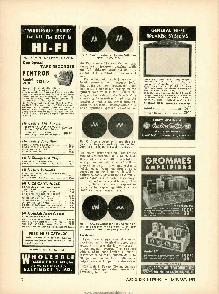
"WHOLESALE RADIO- For ALL The BEST In
HI -FI ENJOY HI -FI RECORDING PLEASURE!
Duo -Speed TAPE RECORDER
PENTRON Model 9T3C $1 34.50
Complete with crystal mike. 600 ft. reel of plastic tape and empty 5" reel. Life like reproduction. Superlative features and styling. Semi in operation. At the posh of a button, provides two full hours recording on a 7" reel (3'1" per sec. 50 to 5.000 cycles) one fell hour on a 7" reel (7'.6" per sec. 50 to 8.000 eyelet). Has last forward and rewind speed, 20 to 1, or 70 see. for 1200 ft. Fire watts audio in 6" Alnico V speaker. Additional features Include editing key; maple eye recording in "icatrr; crystal mike: mike and radio input lacks; separate record and era e heads. 110 s. AC. Wt.: 27 lbs. A really great portable tape recorder unmatched at this price.
Hi- Fidelity FM Tuners! BROWNING RV -31 FM TUNER $99.so Complete With Power Supply PILOT FM -AM TUNER
99.50 New Design! Self Power Supply
Hi- Fidelity Amplifiers GROMMES 50PG. 10 watt aadie 8 55.00 BELL 2122 -B. 10 watt audio 50.46 ALTEC A -433A. 15 watts 111.50 ALTEC Pre -amp. A433A 75.00
Hi -Fi Changers & Players GARRARD 3 spd. changer. RC -80 42.30 REK -O -KUT 12" Turntable. 3 spd. LP743 54.95
Hi- Fidelity Speakers ALTEC LANSING 12" DUPLEX 601A Including N3000Á Network $ 89.00 ELECTRO -VOICE SP12B 5 27.00
Hi -Fi CE CARTRIDGES GE RPX -050 with dual reversible sapphire
styles. 3 spd. GE RPX -051 (Less Styles). 3 spd. GE RPX -052 with combination diamond
and sapphire stylus. 3 spd. GE RPX -040 with .003 sapphire GE RPX -041 with .001 sapphire GE RPX -042 (Less Stylus) GE RPX -046 Professional type (less stylus) .
GE RPX -047 Broadcast type (less styles) 3 spd.
$ 8.37 5.28
23.37 5.97 5.97 4.25 6.87 9.27
Hi -Fi Audak Reproducers! 3 SPEED! POLYPHASE! Model L6 Head for all lateral records $20.70 Model L6G For Garrard Changer (Plug -In) 23.40 Model L6W For Webster Changer IPlat -In) 23.40 All models complete with two genuine sapphire Jewele.
FREE! HI -FI CATALOG Write for free Hi -Fi catalog featuring newest equipment and advice on high fidelity systems.
Address Orders To Dept. AE -1
WHOLESALE RADIO PARTS CO., Inc.
311 W. Baltimore St. BALTIMORE 1, MD.
70
Fig. 9. Acoustic output at 55 cps. Left, bass reflex; right, R -J.
the R -J. Figure 12 shows that the bass reflex is still frequency doubling, while the R- J- -although somewhat down in output -still maintains the fundamental tone.
The ability of the R -J system to handle power without frequency doub- ling at the very low frequencies is due in the main to the air loading on the speaker cone which is the result of the design. This loading is also beneficial in increasing the transient damping of the speaker as well as the power handling capacity. Transient damping which cuts clown spurious speaker vibration of
Fig. 10. Acoustic output at 48 cps. Note be- ginning of frequency doubling from the bass reflex at the left; the R -J is still fundamental.
"hangover" after the signal has ceased may be demonstrated in a simple test. If a small direct current from a battery is keyed on and off, a "click" will be noticed on circuit make, and either a "click" or a "bong" on circuit break, depending on the damping.$ It will be noticed particularly with the bass reflex, which exhibits a definite "click -bong" as the circuit is made and broken, while the R -J shows its transient response to be better by responding with a "click - click" for the same treatment.
Fig. 11. Acoustic output at 44 cps. Output from boss reflex is seen to be almost 100 per cent
harmonic, due to frequency doubling.
Conclusions
From these comparisons, it may be concluded that although it is based on a resonant principle, the R -J enclosure is a non -resonant system. The response with a 12 -in. cone having a free -air resonance of 63 cps is smooth down to 50 cps, and has usable but attenuated output down to 30 cps. It is also shown
5 Benjamin B. Drisko, "Getting the most out of a reflex -type speaker." AUDIO EN- GINEERING, July 1948.
AUDIO
Here's the famous Baruch -Long complete speaker system at a new low price. Contains four special 5" speakers in acoustically de- signed corner cabinet 13" high, 19" wide, 93/4" deep. Available finished in Mahogany, Blond or Black, or unfinished, less frame and grille cloth as a basic speaker for P.A. appli- cations. Impedance 4 ohms, may be rewired for 16 ohms. With 15 ft. plastic cord termi- nating in 2 alligator clips. Shag. wt. 12 lbs.
GENERAL HI -Fl SPEAKER SYSTEMS
Unfinished Net 2495 Finished (Specify Coter) Net 2995
ARROW ELECTRONICS'
BEAUTY Ih SOUND
65 (ORTLANDT ST., NEW TORN 7, N. T., INGOT 9 -4714
GROMMES AMPLIFIERS
Model 50 PG
. .w.. o 30 IN TO
m " ;500
...,. w .M, A. pw,.... r -.n. r++x
awe, .; ... .,r. v..... r"...... "
.e.....: 0e. TO ,. 20.004 a.. . S .....,.
WRITE FOR CATALOG
Vierkt
PRECISION ELECTRÒÑICS, li s
9101 Kin! Averue,.Franklin Part, Ill.
ENGINEERING JANUARY, 1953
www.americanradiohistory.comAmericanRadioHistory.Com
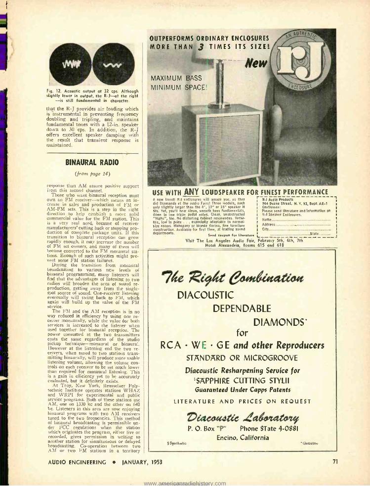
Fig. 12. Acoustic output at 32 cps. Although slightly lower in output, the R -J-at the right
-is still fundamental in character.
that the R -J provides air loading which is instrumental in preventing frequency doubling and tripling, and maintains fundamental tones with a 12 -in. speaker down to 30 cps. In addition, the R -J offers excellent speaker damping with the result that transient response is maintained.
BINAURAL RADIO
(from page 14)
response than AM assure positive support from this second channel.
Those who want binaural reception must own an FM receiver -which means an in- crease in sales and production of FM or AM -FM sets. This is a step in the right direction to help establish a more solid commercial value for the FM station. This is a very real need, because of receiver manufacturers' cutting back or stopping pro- duction of complete package units. If this transition to binaural reception can grow rapidly enough, it may increase the number of FM set owners, and many of them will become converted to the FM monaural sta- tions. Enough of such activities might pre- vent some FM station failures.
During the transition from monaural broadcasting to various new levels of binaural programming, many listeners will find that the advantages of listening to two radios will broaden the area of sound re- production, getting away from the single - spot source of sound. One- receiver listening eventually will swing back to FM, which again will build up the value of the FM service.
The FM and the AM reception is in no way reduced in efficiency by using one re- ceiver monaurally, while the value for both services is increased to the listener when used together for binaural reception. The power consumed at the two transmitters costs the sanie regardless of the 'studio pickup technique -monaural or binaural. However at the listening end the two re- ceivers, when tuned to two stations trans- mitting binaurally, will produce more usable listening volume, allowing the volume con- trols on each receiver to be set much lower than required for monaural listening. This is a gain in efficiency yet to be accurately evaluated, but it definitely exists.
At Troy, New York, Rensselaer Poly- technic Institute operates stations WHAZ and WRPI for experimental and public service programs. Both of these stations use AM, one on 1330 kc and the other on 640 kc. Listeners in this area are now enjoying binaural programs with two AM receivers tuned to the two frequencies. This method of binaural broadcasting is permissible un- der FCC regulations when the station which originates the program, either live or recorded, gives permission in writing to another station for simultaneous or delayed broadcasting. Co- operation between two AM or two FM stations in a territory
OUTPERFORMS ORDINARY ENCLOSURES
MORE THAN 3 TIMES ITS SIZE!
New MAXIMUM BASS
MINIMUM SPACE
USE WITH ANY LOUDSPEAKER FOR FINEST PERFORMANCE A new trend! R -1 enclosures will amaze you, as they did thousands at the Audio Fars! Three models, each only slightly larger than the 8 ", 12" or 15" speaker it fits. Yet, you'll hear clean, smooth bass fundamentals, down to low organ pedal rotes. Clean, unobstructed "highs ", too. No distorting cabinet resonances. Versa tile, low in price ... especially adaptable to normal - size rooms. Mahogany or blonde Korina, fine furniture construction. Available for first time, at leading sound departments. Send coupon for literature L_
R.1 Audio Products 164 Duane Street, N. Y. 13, Dept. AE -1 Gentlemen: Please send literature and information or R -1 Speaker Enclosures.
Name
Address
City .State
Visit The Los Angeles Audio Fair, February 5th, 6th, 7th Hotel Alexandria, Rooms 615 and 618
74 Rid /a euitedasatioa DIACOUSTIC
DEPENDABLE
DIAMONDS' for
RCA WE GE and other Reproducers
STANDARD OR MICROGROOVE
Díacoustíc Resharpeníng Service for 'SAPPHIRE CUTTING STYLII Guaranteed Under Capps Patents
LITERATURE AND PRICES ON REQUEST
Synthetic
Dc'acoadtec 4agetuu`l P. O. Box "P" Phone STate 4 -0881
Encino, California Genuine
AUDIO ENGINEERING JANUARY, 1953 71
www.americanradiohistory.comAmericanRadioHistory.Com
SONOCRAFT FM TUNER $8995
Modem design throughout. Compact size ;; (only 4%" high x 10" wide) permits use
as a replacement in almost any type of : music system, bringing it up to present day standards.
:: DESIGN FEATURES Novel blackout tuning indicator in VTVM circuit Drift free- Automatic Frequency Control
5 Microvolts sensitivity AFC can be disabled in strong signal areas Full Armstrong circuit -completely shielded
Exclusive design of dial plate provides fnr simple cabinet installation
.................... .................... .... ............. ...............................
NOW OPEN A new studio designed for you -right in the heart of New York City. America's finest and most flexible sound demonstration studio -At last you may experience the breathtaking realism of reproduced music.
WRITTEN FOR
MUSIC LOVERS
BY
IRVING GREENE
124 pages - chock full of valu
able information and listings of
high fidelity components. Net. EA
ALLIED OUND CORPORATION
115 WEST 45 STREET (3rd FLOOR)
NEXT TO TIMES SQUARE NEW YORK 36, N. Y. LUxemburg Y -1750
72
served by both could be the means of binaural broadcasts. As good -will builders and long -range public relation service it has great value.
In television and movies, another handi- cap is added to nature's facilities by using a single -lens sight pickup on the camera. These two handicaps add to a condition where both sight and hearing are fatigued more rapidly than in nature where two ears and eyes are used normally, as at the opera, stage, or concert.
Binaural radio sound reproduction pro- vides nature's two -ear listening facility and when stereo television with binaural sound becomes available fatigue will be greatly reduced. Many observers agree that (two ear) binaural radio broadcasts will fatigue us less rapidly and keep us alert to the program -including the sponsor's message -for a longer period. This may help the sponsor make a deeper impression on the listener against the chatter of those as- sembled at home to hear a favorite pro- gram, even though these listeners are using it for atmosphere background.
Activities in 1952 In late October 1952 binaural broadcast-
ing in New York was introduced at the Audio Fair, and its impact is still being felt. Station KOMO in Seattle in the same month did a successful broadcast which struck a high level of local appreciation.
Station WJR in Detroit used its AM- FM stations to produce two binaural broadcasts each week for eight weeks dur- ing July and August. These broadcasts were enthusiastically received by hundreds of hi -fi fans with their wider range AM- FM combinations, and a big audience of listeners using package AM and FM re- ceivers. These concerts featured the De- troit Symphony Pops Orchestra under the direction of Ed Werner at the Jefferson Beach open -air music center. Detroit news- papers carried a continuous one- column cut showing a diagram for a receiver setup at home. Spot announcements daily kept the audience growing. Future plans are soon to be announced.
Station WQXR in New York agreed early in September to program an AM -FM broadcast for the banquet entertainment at the Fourth Annual Convention of the Audio Engineering Society on October 30. This finally resolved in two binaural broad- casts sponsored by Magnecord, Inc. on October 29 and 30. The October 29 broad- cast used a binaural Magnecorder and a completely taped show. The program on October 30 was produced by WQXR's musical staff with a live 28 -piece sym- phonic ensemble and two voices. In the ballroom of Hotel New Yorker, the ban- quet guests listened to the radio reproduc- tion from Electro -Voice Patrician speakers fed by Fisher Radio Corporation tuners and amplifiers. Norman Brokenshire, well - known announcer. gave his hearty approval from the studio where he was listening "off- the -air" to two RCA table model re- ceivers. This program was the first known binaural network broadcast, as it was re- layed by FM radio to WDRC -FM on Mount Meriden in Connecticut, and the AM was piped by telephone line to WDRC studios in Hartford, Connecticut.
Both WQXR and WDRC were swamped with phone calls from a large audience, and requests for more binaural broadcasts fol- lowed by mail. These requests were ful- filled on November 9 when the Harvey Radio Company of New York started a 52 -week series of one -hour binaural broad- casts in co- sponsorship with Magnecord, Inc. The program is the regular WQXR
for every application ...
ATLAS MIKE STANDS
most complete - most diversified line in the world!
From a professional boom stand to a flexible goose neck to a tiny. fitting- whatever your need in mike stands and accessories - depend on it, ATLAS has it for you. Designed and manufac tared for highest stability, quiet, ease of operation, dura- bility. And backed up 100% by ATLAS -world leader in mike stands, public address loud speakers and accessories for 21 years. Compare them all at your dis tributor- You'il make your next mike stand an ATLAS.
P,S e.hll
ATLAS SOUND CORP. 1448 -39th Street, Brooklyn 18, New York h, coodo .oio, tod,o coop. t,d. Toro,,,, One
THE AUDIO FAIR is for you The Hi Fi Audiophile!
The Cortcertone was designed for you and incorporates the following modern developments at no extra cost.
High speed forward and rewind Simultaneous monitoring from tape Use of professional reels Built -in equalization and speed change
It is the acme of Hi Fi performance
Network
Recorder
NWR.1
See and compare before you buy. We will gladly demonstrate it in our audiotorium. We carry a complete line of Hi Fi equipment.
Q1LL Ú E
7120 MELROSE OSE AVENUE k LOS ANGELES 46, CALIF. .t k,
Telephone WEhster 3 -5545
AUDIO ENGINEERING JANUARY, 1953
www.americanradiohistory.comAmericanRadioHistory.Com
String Quartet from a to p. w. each z,un- day. This show is well produced and the effect is thoroughly realistic.
Beginning January 3, WQXR will pre- sent each Saturday from 4:30 to 5:00 p. m. through January, February, March, and April, a series of organ recitals by outstanding members of the American Guild of Organists. These programs will originate from Temple Emmanu -El under the direction of Dr. Hugh Giles, Chairman of the Guild and organist at Central Pres- byterian Church in New York.
\VDRC in Hartford is revamping one of its studios (20' x 28' x 16') for binaural programming. WDRC is owned and oper- ated by F. M. Doolittle, mentioned earlier as the daddy of binaural broadcasting.
WNYC, New York City's municipal sta- tion, arranged, to have Mayor Impelliteri give his Christmas Day message binaurally. It is also planned to broadcast an intensive binaural series from February 12 to 22 with the entire annual American Music Festival, including the United States Army Band and the New York Philharmonic Orchestra directly from Carnegie Hall. As a series, these binaural broadcasts will be the most pretentious yet to be performed, and should go far to establish binaural radio programming.
Station \VGAR in Cleveland has re- cently clone a series of nightly 15- minute programs of binaural tape with encourag- ing audience reaction. One listener said his dog ran back and forth from one radio to the other to catch the ping -pong ball re- produced binaurally during the program. Intensive plans are under way for both live symphony and tape shows to satisfy a big audience.
Station WCAE in Pittsburgh produced a series of successful binaural broadcasts in November, using tape and live orchestra. The station plans to do a great deal with binaural programming in 1953.
These brief comments about binaural broadcasts and plans for the stations men - tioned were picked up in telephone con- versations with program personnel at each station early in December. The personal enthusiasm of each individual reflects the spirit necessary to bring healthy changes into broadcasting. This article was not in- tended to he technical. For those interested, reference should be made to the excellent article "Stereophonic Sound Reproduction" by James Moir of England, which appeared in the September issue of 2E.
REVERBERATION UNIT Now made EXCLUSIVELY in improved form
by AUDIO INSTRUMENT CO., INC. Simulates :- everberation of a room of any size, using a magnetic tape loop system with FIVE heads. Switch- ing heads produces various special effects, as well as natural reverberation.
MODEL 40 Compact: single 83/ " x 19" panel Levels: Input, -30 dbm or +4 dbm at 600 ohms
Output, -30 dbm or +4 dbm at 600 ohms Controlled by switch on chassis
Variable equalisation: Built in, for special effects Reverberation time: Up to ten seconds, continuously variable Delivery: Six weeks
Da"`-
ud1 G INSTRUMENT
re/, o COMPANY INC
Dept. 133 WEST 14th STREET, N.Y. 1 I ,N. Y.
NOW AVAILABLE ThetRAMOION Feedback Disk Recording Cutterhead Unit
Engineers and musicians now realize a perfect transient response of any recording system is of paramount importance -the Grampian cutterhead with its precision -made true balanced armature and flux correcting feedback loop obtains this ideal. Used by international broadcast networks where fidelity is of primary importance, you too, can be assured of the highest fidelity disk recording.
Many outstanding recordings, such as the LP Mercury Olympian Series, were recently produced with the Grampian. For more Information, write to Wide frequency range
30 c/s to 20 Ice
Low Distortion Superior transient re- sponse
R E E V E S
IO EAST 52nd E Q U I P M E N T C O R P.
STREET NEW YORK 22, N. Y., U. S. A. CABLE- REEVESOUIP, N. Y.
protect your SOUND INSTALLATION profits! use
J.,. , .S,. unan
"We're the repair men for your binaural sound system."
AUDIO ENGINEERING JANUARY, 1953
LOWELL speaker housings and baffles
Lowell's "complete package" give speaker POSITIVE PROTEC- TION from dust, mortar . cuts installation time . assures beautiful job! Baffles have "floating conical action" to give clear, distortion -free, low level sound diffusion!
Lowell 22 gauge steel back cover speaker can (spot welded to 22 gauge steel plaster ring) protects recessed speakers in new or remodeling installations. Sectional view of completed assembly using AL Series flush mounting low ceiling baffle. AL Series baffles for 6" to 15" speakers. BL Series surface mounting baffle for normal height ceilings; for 6" to 12" speakers.
Write for complete catalog and prices.
LOWELL MANUFACTURING COMPANY 3030 Laclede Station Rd., St. Louis, Missouri
In Canada: Atlas Radio Corp., 560 King St., West, Toronto, Ontario
73
www.americanradiohistory.comAmericanRadioHistory.Com
/4DCOLP\ SOLDERING
INSTRUMENTS Any Voltage Range Supplied from 6/7 to 230/250 volts.
Our instruments for 110 volts are superb in making
SOUND JOINTS
for all
SOUND EQUIPMENT
Supplied to leading British electrical manufacturers and H.M. and foreign govern- ment departments.
These soldering instruments are named instruments as they are such a complete departure in design from the usual solder bolt or iron
' and are ideal for all modern assembly and maintenance
v work on telecommunica- o tions, radar, television, wire-
less, etc. M 3/16" dia. bit Standard
Models
lli 3/16" Detachable Bit Type (Factory Bench Line)
Heating time: 90 seconds Consumption: 25 watts Weight: 4 ozs. High temperature Handle unaffected by element temperature Length of instrument: 9" Equally suitable for daily or intermittent use Prices ex Works.
Standard 3/16" Bit Model 83.60 Standard 1/4" Bit Model 4.00 Detachable 3/16" Bit Model 4.80
alogue sent free on request. MADE IN ENGLAND
Registered Design (U.S.A., British, es Foreign Patents)
Wr te direct to sole manufacturers and suppliers:
Ca
ADCOLA PRODUCTS, LTD. CRANMER COURT
CLAPHAM HIGH STREET LONDON, S.W. 4, ENGLAND
Read ESSENTIALS OF
MICROWAVES By Robert 13. Muchmore, Hughes Aircraft Co.
An expert's practical survey of the physical prin- ciples of microwaves and applications of microwave equipment. Word pictures replace complicated mathematics. 1952. 236 pages. 84.50.
JOHN WILEY Ca SONS, INC. 440 -4th Avenue New York 16
Write for a copy on 10 day approval.
74
AUDIO
TRANSFORMER [front page 44]
represents 2 db, and 99 per cent repre- sents 0.23 db.
The use of the charts in Figs. 5 and 6 to determine efficiency is illustrated by Fig. 7. Figure 5 is used to find the maxi- mum efficiency of which a transformer is capable, and the relation between the actual operating impedance of the trans- former and that producing this maxi- mum. Figure 6 then gives the actual efficiency from this information. no is the total winding resistance referred to the winding chosen for making the cal- culation; Rp is the shunt loss due to the core, referred to the same winding, and measured at a mid -frequency of, say 1000 cps. (Although somewhat lower frequencies are often taken for mid - frequency for other audio purposes, 1000 cps gives a fairer picture for audio transformer efficiency). An impedance which is the geometric mean of no and Rn results in maximum efficiency, and this maximum efficiency is given by the n scale on Fig. 5. At the same time, reference in the manner shown in Fig. 7 gives a value of Zone /Z, indicating by what ratio the actual impedance, Z, at which the reference winding is operat- ing, differs from Zopt, which gives this maximum efficiency.
The maximum efficiency point is not always the best impedance at which to work a transformer, because frequency response must be considered as well, and in smaller models harmonic generation may also affect the consideration.
Having found what the efficiency is for one particular impedance, the con- struction of the charts avoids the neces- sity for going through the whole pro- cedure again for another impedance; the efficiency for the new impedance may simply be read off from a different point on the same curve of Fig. 6.
Harmonic Generation
This is a relatively simple calculation, so no special chart has been provided for it. The previous article gave a method of measuring harmonic content as a percentage of fundamental magne- tizing current. Magnetizing current at the frequency and amplitude concerned can be expressed as a shunt impedance referred to the primary. The source impedance and load impedance referred to the primary can also be expressed as a combined shunt impedance. To find the effective harmonic percentage gen- erated, the percentage measured is then divided by the ratio between the shunt impedance due to magnetizing current and that due to external circuit im- pedances. For example, if the measured percentage is 15 per cent, the shunt im- pedance due to magnetizing current 50,000 ohms, the plate resistance 20,000 ohms, and the referred load resistance 5000 ohms: the external shunt imped- ance is 4000 ohms, and the effective
eniCet(Vilt maintains its leadership through constant achievement Concettone's leadership in the field of high fidelity recording is maintained by con- stantly improving the quality of Concertone magnetic tape recorders.
Concertone engineers continually incor- porate advancements into the design - thereby keeping consistently ahead of the field. Concertone recorders never become "dated" or outmoded. Now. more than ever before, Concertone is truly the standard of high fidelity performance.
Professional users' net prices begin at $345.00. Write for literature.
Network
Recorder
NW R -1
Mamifaeturec by
iBerlant Associates 4917 W. tefferson Blvd., Los Angeles 19, Calif.
104444... e FREE!
TERMINAL'S New, Illustrated, 1310 -page
AUDIO CATALOG
Your complete guide to the Finest in Audio Equipment f
Write or come in for vou- FREE Comp imentary taw!
Visit cur Audio Dept. Open Rots. eves. till 9 P. M.
Ample Porting Space after 6 F. M.
Terminal Radio Corp. L85 Cortlandt St., New York 7 j
AUDIO ENGINEERING IANUARY, 1953
www.americanradiohistory.comAmericanRadioHistory.Com
4
i 15x4
harmonic generation. ,o 12 per
cent.
Input Transformers
Insertion loss in an input transformer is usually unimportant compared with its frequency characteristic and other properties. It is normally direct coupled, but with no d.c. polarizing. Due to low signal levels, working flux densities in the core are extremely small, and the effective primary inductance varies over a considerable range with variation of signal level. Inductance should be suffi- cient to maintain good response, even with its smallest value. If it is not suffi- cient to do this, the only remedy is to reduce the working impedance by addi- tional shunt resistance, which will also add insertion loss -at a point it can ill be afforded; so generally a compromise is necessary, or a better transformer.
Its h.f. response is generally deter- mined as to range by the impedance to which the source is matched by its step - up, and the input capacitance of the tube it feeds. Sometimes an h.f. peak appears, as will be shown by use of Fig. 1. In such cases increase in input capacitance pulls down the frequency of peak, but usually increases its height ; the best remedy is an appropriate value of shunt R across the secondary. If this restricts the range more than is desired, tube input capacitance must be reduced as well, by the use of a little inverse cur- rent feedback (leaving off the cathode by -pass capacitor). The only alternative is another transformer with less step -up.
If the whole chain has a deficiency in highs that can be corrected by peaking, the input transformer is a good place to introduce such correction, because it will boost the highs in the signal before the thermal noise of the first stage is added to it.
Shielding against hum pick -up is not one of the properties within the scope of this article, but it is important for some input transformers, and so should be mentioned. Some reduction can al- ways be effected by orientation, but if shielding is totally inadequate the only answer is a better shielded job.
lnterstage Transformers
Direct -coupled types carrying d.c. polarizing usually have larger leakage inductance and self -capacitance than types without provision for d.c. polar- izing. If low frequencies are deficient. the best remedy is to shunt the primary with a suitable resistor. This will by- pass some of the polarizing current, thereby increasing inductance slightly, and at the same time reduce effective source impedance. But this shunt re- sistance may produce a peaking effect in the h.f. response. As with input trans- formers, this may be overcome by suit- able shunt resistance across the second- ary. The charts can be used to find the best combination more readily than protracted trial and error, taking a fre- quency run each time a change is made.
WILL Asoir HIGH
FIDELITY
&dog,/ Point one feature of the Partridge -Williamson WWFB
Audio Transformer -you are assured from the word 'go' of the performance exactly as intended by the designer.
Point two -you can get that performance 'off the shelf" from any good radio jobber -for the WWFB is now avail.
able to all -there is now no need to suffer anything less than the best- remember there just is no substitute for
the Partridge- Williamson (vide "Audio Engineering"- Nov 1949). Your assurance is in the fact that no WWFB
leases our works without being individually tested to make store it lives 'up to specification'.
If in difficulty. don't hesitate, write us direct giving your jobbers address we still see that 4011 are supplied
without delay.
PRICE
$26.00 duty paid
PARTRIDGE- WILLIAMSON # au4fe/
PARTRIDGE TRANSFORMERS LTD., TOLWORTH, SURREY, ENGLAND
35 POUNDS OF STUDIO QUALITY
-4K PORTABLE AMPLIFIER
AC OR BATTERY OPERATION banishes power failure problems.
ELIMINATES ANNOYING HISS, hum and microphonics.
"WOOFRIG" NO LONGER NECESSARY. Unit includes a 400tycle tone oscillator. An original G -E development.
PLUSlow level output with volume control, shock mounting, test :one, and high gain cue circuit for noisy locations.
SEND FOR FREE BULLETIN General Electric Co., Sec. 4413 Electronics Park, Syracuse, N.Y.
AUDIO ENGINEERING JANUARY, 1953 75
www.americanradiohistory.comAmericanRadioHistory.Com
SAVE
33,E
This is our
GROUP SUBSCRIPTION PLAN
You and your friends and co- workers can now save up to $1.00 on each sub- scription to AUDIO ENGINEERING. The more men in a Group, the more each saves. If you send 6 or more sub- scriptions for the U.S.A. and Canada, they will cost each subscriber $2.00,
1 /3 less than the price of a regular 1 -year subscription. Present subscrip- tions may be renewed or extended as part of a Group.
AUDIO ENGINEERING is still The only publication devoted entirely to Audio- Recording Broadcasting equipment Acoustics Home reproduction systems PA systems Psychoacoustics
Please print,
Name
Address
Position Company
Nam Address
Position Company
Name
Address
Position Company
Name
Address
Position Company
Name
Address
Position Company
Name
Address
Position Company
Add $.50 to each Foreign subscription ordered
RADIO MAGAZINES, INC. P. O. Box 629, Mineola, N. Y.
76
Parallel -fed types of interstage trans- former may cause peaking at one or both ends of the audio spectrum. In general it is best to avoid peaking at the 1.f. end, aiming at a value of L /CrR greater than unity, so that variation of inductance with level produces a minimum varia- tion in response. However, going too far in this direction may restrict the l.f. range more than is desired; so the charts may be used to find the best compromise. using two different values of inductance (extremes of variation with level) to see what effect signal level can have on response.
The h.f. end will be easier to handle, because with most parallel -fed compon- ents there is more in hand. The limit to step -up is generally set in the same way as for input transformers.
Some points should be noted here that help in getting just the right effect at both ends of the spectrum at once. Re- sistance across the secondary has the effect of reducing tendency to peak at both ends, although maybe in different degrees, according to relative values of L /CrR for each end. Varying the cou- pling resistor also has a similar effect at both ends, but possibly different in degree. Usually if the secondary shunt resistor has more effect at one end, the value of coupling resistor will have more effect at the other. But a resistor in shunt with the primary (after the coupling capacitor), has opposite effects at each end: at the l.f. end it is the same as an equivalent referred value shunted across the secondary, and so reduces the tendency to peak ; but at the h.f. end it shunts the source resistance, reducing the value of r, so increasing the tendency to peak.
Thus adjustments of coupling resistor, coupling capacitor, shunt primary re- sistor, and shunt secondary resistor, af- ford a considerable variety of possibili- ties with the parallel -fed type of inter - stage transformer. Exploration of these possibilities to find the best combination can be greatly expedited by use of the chart,.
Output Transformers
In output transformers everything takes on different proportions. The transformer is step -down, and most cir- cuits-even using tetrode or pentode outputs (inverse voltage feedback being invariably used) -have an effective plate resistance that is but a fraction of the referred load resistance; so peaking at h.f. is impossible. Instead, harmonic generation and efficiency are now the features to watch. If harmonic genera- tion at the lowest frequency of interest is kept low, I.f. response also will usually be taken care of. The charts in Figs. 5 and 6 will be useful in working out effi- ciency, particularly to determine whether a transformer designed for operation be- tween, say, 7000 and 5 ohms, will serve satisfactorily between 10,000 and 7 ohms, or between 5000 and 3% ohms.
The remarks here made about output transformers also apply to loudspeaker and line -matching transformers.
CLASSIFIED Rates: 10e per word per insertion for noncommercial advertisements: 25e per word for commercial saver. tfsements. Rates are net. and no discounts will be
allowed. Copy must be accom panied by rem ittance In
toll, and must reach the New York office by the first of the month preceding the date of Issue.
THE .\l7HV i x ii.\Nt;4:, INC. buy. ,us sells quality high -fidelity sound syhtems am components. Guaranteed used and new equip nient. Catalogue, Dept. .E, 159 -19 Hillside Ave., Jamaica 32, N. Y. Telephone OL 8-0445
PRESTO 16 -in. RECORDER, Model "Y." Complete with two channel inputs, two speeds -33% and 78, hi -fi amplifier, and cutting head. Good condition. Best offer over $300. W. A. Karr, 8033 Woodlawn, Chicago 37, III.
CUSTOM Ultra- Linear Williamson Ampli- fiers, $89.50. Send for photos and facts. Dr. Nicely, Kenton, Ohio.
SOUND LEVEL METER, Western Electric Model 700A. Perfect condition. $250. Box 4554, Jacksonville, Florida.
WANTED -Used Semi -professional tape re- corder, Twin -Trax or similar. Yalcin, 822 Hanshaw Road, Ithaca, N. Y.
FOR SALE : McIntosh 20 -W -2 with AE 2A, $175, by check or money order. Raymond, 17 Oak Park, Tacoma 9, Washington.
DISC- RECORDING SERVICE Top -quality discs cut from your tapes or
records. All sizes, all speeds. Twenty -four hour service for small quantities. Price for 10 -in. LP record, $2.25.
UNIFA, INC. 80 -08 135th St., Kew Gardens, N. Y.
Llggett 4 -1203
WESTERN ELECTRIC KS -12025 horn with or without WE Hi -lei surplus driver and 800 -cps crossover. Telephone Brooklyn (N. Y.) SH 8 -4546.
AMPLIFIERS FOR SALE : Altec A -323, like new, $50; Stromberg- Carlson, 10 -watt, new, $50; Amplifier Corp. of America ACA -1000, new, $100; Scott amplifier with noise sup- pressor, $150 ; Presto disc recorder, Model K, like new, $180. H. Untried, 33 Westfield Rd., ituialo 21, N. Y.
FOR SALE : 30 rolls (800 ft.) single per- forated Scotch Brand magnetic 10-mm film, No. 116 -new : University of Minnesota, Pur- chasing Department, Minneapolis 14, Minn.
STEPHENS P15 in perfect condition $25. David Fonseca, 555 Notre Dame Ave., Chatta- nooga, Tenn.
FOR SALE : H. H. Scott type 410 Sound Level Meter complete with leather case. Like new, complete with batteries, instruction book. Bargain, only $150. Box CJ -1. AUDIO ENGINEERING.
NEW G.E. Variable- Reluctance "twist" dual phono cartridges, $5.95 ea. Send for list on all other high -fidelity equipment and com- ponents at great savings. High- Fidelity Guild, Box CJ -2, AUDIO ENGINEERING.
FOR SALE : Tuners- Craftsmen C10, $95 ;
Browning RJ -20, $70. Amplifiers- Crafts- men C500. $80 ; Masco MA- 101IF. $25. Speaker -Electro -Voice 8P12B, $18. Ralph Ashworth, Charlton City. Mass.
AUDIO ENGINEERING JANUARY, 1953
www.americanradiohistory.comAmericanRadioHistory.Com
LEADING WEST COAST AUDIO REPRESENTATIVES
The representatives listed below are for the use of dealers and distributors only. The Hbbiests and Experimenters are requested fo contact their dealer for information.
OXFORD SPEAKERS
Chicago Transformers
Rauland -Borg Sound Systems
J. T. Hill Sales Co. 800 W. 11th St.. Los Angeles 15, Calif.
GARRARD RECORD CHANGERS motors, bases. etc.
R -J SPEAKER ENCLOSURES BRITISH INDUSTRIES PRODUCTS
Leak. Wharfedale, etc.
ASIATIC MICROPHONES, Pickups, Cartridges. TV Boosters
CLETRON SPEAKERS, with Aluminum Voice Coil forms.
BELL SOUND SYSTEMS: Three -speed Tape Recorders, Amplifiers, Inter -coins etc.
HARRY A. LASURE COMPANY 9041 West Pico Blvd., Los Angeles 35, Calif.
CRestview 6 -4185 BRadshaw 2 -7307
MARSHANK SALES CO. 672 So. Lafayette Park Place Los Angeles 5, California Phone Dunkirk 7 -8235
REPRESENTING Bogen - University - Hallicrafters - Turner
Audio Components
Douglas H. Loukota Co. Cleveland 6 -2286
6137 York Blvd. Los Angeles 46, Calif.
PERLMUTH -COLMAN and ASSOCIATES
1335 So. Flower St.
Los Angeles 15, Calif.
OUR 30th YEAR representing
AUDIO and SOUND Mfgs. in
California, Arizona, Nevada
Travelling 8 Salesmen
PERLMUTH- COLMAN and ASSOCIATES
1335 So. Flower. !.os Angeles 15, Calif.
DuBois -- British Tri -Sol So der; Deotone - needles, blanks, tape; Johnson -Sockets, Jacks, Pilot lights, Knobs; Racon -- Public Address Speakers; Radio Receptor -R rctifiers; Speak -o- phone -Tape Recorders; Trimm- Headphones.
Don C. Wallace Cr Wuhan M. Wallace 1206 Maple Av. L. A. 15 -RI 70401
COLLARO Record Changcrs FAIRCHILD Disc and Tape Equipment TECH LABS Reverberation Generators
KITTLESON COMPANY Telephone Whitney 1167
7614 Melrose Ave., Los Angeles 46, Calif.
CARL A. STONE ASSOCIATES, INC.
1102 5. Western Ave. 420 Market Street Los Angeles 6, Cal. San Francisco 11, Cal
Republic 2 -8103 Exbrook 2 -4009
We Invite You To Hear H. H. Scott Inc. 214 -A Amplifier
Browning Lab. Inc. RV 31 FM Tuner Room 649
Henry Feldman Company
Tape Recorders and Accessories
Acoustone Hi Fi Grill Cloth
Utah Loudspeakers Cr Baffles
Telephone: Underhill 0 -3594
GEORGE DAVIS SALES CO. 5259 E. Beverly Blvd., Los Angeles 22, Calif.
PRESTO Recording Corp.
STEPHENS SPEAKERS
ECTRO "Cub- Corder"
Audio Instrument Co. Inc.
LEE OWENS 2331 W. Washington Blvd., Los Angeles 18
flEELY EflIERPRISFS REPRESENTATIVES FOR AMERICA ' S
FINEST SO JND REPRODUCING EQUIPMENT IN CALIFORNIA, NEW MEXICO, ARIZONA, NEVADA
-mom T A P E R E C O R D E R S
M I C R O P H O N E S
mcliIto5h ¿SIGNATURE SPEAKERS A M P L I F I E R S
11EATNEti MARKEL FM PICKUPS RECORD CHANGERS
TELEFUNKEN Products
flEELY EflTERPRISFS Los Angeles
74 22 Melros Avenue Lo, Angeles 46, Calll.
Sacramento 1317 fifteenth Street Sacramento 14, Calif. then,: Gilbert 2 -8901
San Francisco 2830 Geary Boelevard San Francisco 18. Calif
San Diego 1029 Rosecrans Street San Diego 6. Calif.
Albuquerque Phoenix 107 Washington St.. S.E. 32 West Jefferson St. Alhag , N. M. Phoenix, Arizona
AUDIO ENGINEERING JANUARY, 1953 77
www.americanradiohistory.comAmericanRadioHistory.Com
DO YOU HAVE YOURS ?
1 Certifies that beginning
IS P If tf e 1g G,IN,ERING
AUDi UN THE lf
WILL HFOR THE REST OF HIS NC. 5.
CONTINUOUSLY ONTINUOOSL RADIO
PtgE51DENt
If you live in the United States, you can
su scribe for life at the new rate of $25.00. you are already a subscriber, we will refund a pro -rated
amount based on your remaining term, or you can transfer it to a friend. This offer is good only in the U. S. and applies only to subscriptions
entered by sending your check or money order direct t
RADIO MAGAZINES, INC. P. O. BOX 629 MINEOLA. N .Y.
195
TO
SEE and Hear
K'ipschorn Speakers
Dimensitone Speakers Telemusic At room 712 -L. A. Audio Fair
Crawford's of Beverly Hills
456 North Rodeo Drive
Beverly Hills, California
[Langevin rjg Amplifiers
Power Supplies
Transformers
SALES AND SERVICE
THE LANGEVIN CO., INC.
Hollywood San Francisco
RECORDING HEADS. FOR DISC AND TAPE STANDARD AND CUSTOM MODELS
REPAIRS ON ALL MAKES DISC RECORD- ING HEADS AND REPRODUCERS
DIAMOND STYLUS REPLACEMENTS TAPE HEADS . . ALL MAKES REBUILT
OLSON DISC RECORDING HEAD HIGHLY PRECISION HAND- MADE. FLAT TO 15 KC. LOW DISTORTION.
LIPPS TAPE RECORDING HEADS REASONABLY PRICED. HI OR
LOW IMP. CAPS OPTICALLY LAPPED. SPECIAL HEADS TO YOUR SPECIFICATIONS.
E D W I N A . L I P P S E N G I N E E R I N G
MICRO ELECTRO- MAGNETIC INSTRUMENTS ... AUDIO 5485 W. WASHINGTON BLVD., LOS ANGELES 16, CALIF.
WALNUT 4141
78
MONTHLY SUMMARY of product de- velopments MONTHLY velopments and price changes of radio electronic -television parts and
equipment, supplied by United Catalog Pub- lishers, Inc. 110 Lafayette Street, New York City, publishers of Radio's Master.
These REPORTS will keep you up -to -date in this ever -changing industry. They will also help you to buy and specify to best advan- tage. A complete description of most prod- ucts will be found in the Official Buying Guide, Radio's Master -available through local radio parts wholesalers.
Miscellaneous Radio, TV and Electronic Parts BI RN BACH 1111510 -Introduced No. 6261 at $1.14 net and
No. !.'.a ut $1.41 net, both hat -handle renter off switches of molded bakelite, rated at 3 amps, 250 volts.
GENERAL CONTROL -Discontinued Model MX -3. light- weight foot switch.
LITTELFUSE -Added No. 342008 at $.55 list to their 3.LG fuse extractor post series.
MERIT TRANSFORMER- -Added No. IIVO -9 to their TV component series of horizontal output and hl- voltage transformers at $6.00 net.
PORCELAIN PRODUCTS- Introdn ed a series of porcelain lead -in tubing for l'IIP TV cable. This set comes in 7
different lengths from 3 feet to 12 feet. and prevents entry of rain or Insects.
PREMIER METAL PRODUCTS -- Introduced new serles ARP, aluminum rack panels.
R.C.A. -Added TV component part No. 232T1, universal type horizontal deflection transformer (auto. trans. type)
at $6.30 net.
RAM ELECTRONIC SALES -Decreased peke on full focus deflection yoke No í'70P30/3 to $6.00 net.
STANDARD TRANSFORMER-Added deflection yokes No. DY -1A at $4.74 net No. DY -7A at $5.37 net .
No. DY -8A at $6.60 net . . No. DY -9A at $6.60 net and No. DY -10A at $6.60 net, all with leads and net- works added.
Recording Equipment, Speakers, Amplifiers, Needles, Tape, Etc.
AST AT I C CORP. Discontinued Model S >, rry,tal pickup arm.
AUDIO DEVELOPMENT -Discontinued No. 11IA, micro- phone cable transformer.
GENERAL ELECTRIC -Added No. RPX -052 at $38.95 list and No. RI'X -053 at $57.90 list to their triple play variable reluctance cartridge aeries. Also added No. RPX' 061 at $33.95 list and No. RI'X -063 at $33.95 list to their variable reluctance cartridge series.
PACIFIC TRANSDUCER -Added Model 201D at $33.00 net. This model is the same as Model 201. a wide -range variable reluctance cartridge with a frequency velocity response to above 12,000 cps and with an output of 6O millivolts, with a diamond stylus instead of a
standard sapphire stylus.
PERMOFLUX CORP.-Added No. DIIS -31B at $50.00 net to their monaural dynamic headset line. Also added No PIIA -6 at $8.00 net and PILA -8 at $13.00 net to their line of headband.
RECOTON -Discontinued their serles of joke box osmium phono needles.
Test Equipment HYTRON- introduced No. 81127, test adapter at $1.45 net.
The test adapter permits easier and faster "topside chassis testing, shire it can be plugged Into chassis sockets with the replaced tube plugged into the top of the adapter.
JACKSON ELECTRICAL INSTR. -added Model 710, selenium rectifier test net at $29 50 net. This pocket size unit tests all selenium rectifiers rated from 20 to 650 ma, and has a variable indicated voltage range from 25 to 300 volts a.e. It is designed to operate on 110 to 125 volts a.c. and includes "line adjust" con- trol to give more accurate readings.
SIMPSON ELECTRIC -increased price on Model 476, Slirroscope, to $197.00 net. This oscilloscope uses a 5-in. cathode ray tube mounted In a vertical position, with the image reflected from a high grade mirror mounted in the adjustable cover at the top of the cabinet, bringing the viewing surface near eye level when used on work benches of normal height. Linear sweep frequency is continuously adjustable in five overlapping ranges from 15 to 60,000
AUDIO ENGINEERING JANUARY, 1953
1
i
1
www.americanradiohistory.comAmericanRadioHistory.Com
ELECTRONIC ENGINEER Senior Project
We are a nationally known com- pany manufacturing a line of magnetic recording and motion picture equipment. We are looking for a Senior Project En- gineer to fill a permanent posi- tion created by the rapid expan- sion of non -military commercial products in the audio sound field. This position is one of con- siderable responsibility where the Engineer guides a new proj- ect from prototype to produc- tion. This work involves liaison with Sales, Management and Production Departments as well as development of production designs. This is a position with an excellent opportunity for a
man with initiative and ability. Liberal employee benefits. Sal- ary open. Give complete resume of educational background and professional experience.
AMPRO CORPORATION 2835 North Western Ave., Chicago 18, III.
BRunswick 8 -4500
PROFESSIONAL DIRECTORY
Custom -Built Equipment
U. S. Recording Co. 1121 Versant Ave., Washington 5, D. C
LIncoln 3 -2705
"EVERYTHING IN HIGH FIDELITY" From Primary Components
to Completed Custom Audio Equipment
KIE F Sound Corp.
820 West Olympic Blvd. Los Angeles 15, Calif. Richmond 7.0271 ZEnith 0271
In Southern California it's HOLLYWOOD ELECTRONICS
(in The Audio Mile) Distributors of Hi Fidelity Components Exclusively
Webster 3 -8208 7460 Melrose Ave. Hollywood 46, Calif.
.90d444 but People e e e
Annual banquet of the Radio Club of America brought forth an assemblage of prominent old -timers long to be remem- bered -among those present and accounted for were Paul Godley, who sent the first Transalantic message; Mal. E. H. Arm- strong, who gave us regeneration, the super -het, and FM; Capt. J. H. Round, who pioneered radio direction -finding while as- sociated with Marconi; Harry Houck, World War I associate of Maj. Arm- strong's, who today is president of Meas- urements Corporation; Art Odgers, presi- dent of Northern Radio Corporation; Lin- coln Walsh, designer and manufacturer of the Brook amplifler -and so on far into the night.
Jerry Kahn, president of Stancor, and Ken Prince, director of Chicago's annual Electronic Parts Show, made rounds of friends while in Manhattan to conduct drawings for Parts Show exhibit space ... Maximilian Weil, president, Audak Com- pany, appears to be the industry's most consistent lender of publicity in national magazines- currently appearing for a one - month run in the January issue of "House Beautiful" . . P. M. Parsons, vice- presi- dent, Kellogg Switchboard and Supply Company, Chicago, announces transfer of general sales offices to 79 W. Monroe St.
Robert W. McElroy has been promoted to newly- created position of director of safety and security for Minnesota Mining R. Manufacturing Co. and subsidiaries . . .
Henry C. Roemer, president, Federal Tele- phone and Radio Corporation, announces appointment of Harold R. Hankins as chief engineer of company's Selenium -Intelin Division . Wilbur G. Small is new manager of exhibits for 'laytheon Manu- facturing Company ... Jack Berman, vice - president in charge of sales for Shure Brothers, Inc., Chicago, for the past 13 years, is resigning to open his own sales rep firm in Southern California effective February first.
Max Baume, formerly sound department director, Hudson Radio & Television Corp., New York, is new sales manager for Brook Electronics, Inc., Elizabeth, N. J.... New .ales and advertising manager for Drake Manufacturing Company, Chicago, is Rex Hanger- appointment announced by Zen- neth Ponta, president . Ralph Glover, product manager of Jensen Manufacturing Company, Chicago, has been named a mem- ber of the RTMA's new High -Fidelity com- mittee-he also heads RTMA Loudspeaker committee . Paul T. Pembrioks, form- erly head of the methods department, has been upped to assistant plant manager of liammerlund Manufacturing Company ... Allen W. Walz has been advanced by Arma Corporation to executive staff assistant to Clifton T. Foss, vice- president in charge of engineering.
Sidney Harmon, recently resigned as vice- president and general manager, David Bogen, Inc., New York, has acquired half interest in the firm of Harmon -Kardon, Inc., also New York, manufacturers of electronics equipment and audio- visual products -firm formerly was known as Kardon Manufacturing Corp. and was owned outright by Bernard Kardon, also a former vice-president. : -nd general man- ager of Bogen . A. J. Nelson Company, Denver, has been appointed sales repre- sentative for Permoflux Corporation in the Rocky Mountain area . Mickey Free- man has resigned as publicity director of KLAC -TV, Los Angeles, to fulfill similar duties for Hoffman Radio Corporation . .
Raymond L. Halley, with Shure Brothers, Inc., Chicago, since 1946, has been ap- pointed comptroller and vice -president in charge of finance.
Terminal Radio Corp., 85 Cortlandt St., New York, has been named exclusive area distributor of the Travis Tapak - new, self -powered, lightweight, pertable tape recorder.
AUDIO ENGINEERING JANUARY, 1953
HEADQUARTERS FOR
SOUND EQUIPMENT
COMPLETE LINE OF
COMMERCIAL AND
INDUSTRIAL SYSTEMS
McINTOSH 50 W-2 AMPLIF!.ER
Largest stock of High Quality Amplifiers, from small single units to large rack installa- tions
fif/ti-16ae SOUND AND RECORDING CO. 1527 CHESTNUT ST.
PHILA. 2, PA. RI -6 -8388
NOW Hear This NEW
D-130 15" Speaker
New pure iron, "high iitensity" casting structure
increases over -all
efficiency
The Mart of a fine loud speaker is its pow- erful magnetic structure. Jim Lansing engineers have been able to produce in the new D -130 a more powerful magnetic beam across the voice coil than ever before possible. This unique design extends the high frequency re- sponse 25% and materially improves the dampening factor. Hear this new Jim Lansing D -130 today ... at your audio dealer's.
Jim Lansing -first in fine sound!
JAMES B. LANSING SOUND, INC. 2439 Fletcher Drive, Los Angeles 39, California
79
www.americanradiohistory.comAmericanRadioHistory.Com
THE OUTCOME OF FOUR YEARS' WORK
Our first advertisement appeared on this page in January 1949. when we were unknown in the U.S.A. Today, four years later, we are still somewhat surprised at our success in spreading a
new concept of musical re- creation throughout the U.S.A.
Our small advertising campaign in- troduced the 215 speaker, but it was performance that established it as the choice of the man who loves music. At $54.00 (which includes $6.00 import duty) it stands as a challenge to all other schools of thought in high -fi- delity systems, so much so that its admirers wish to have the rest of the Hartley audio range.
Hitherto, sheer distance has de- feated our aim to make this readily available, since we believe that Hartley distribution, with its attendant excel- lent technical service is desirable for your full enjoyment. This obstacle is now overcome.
In the immediate future H. A. Hart- ley Co. will have its American head- quarters in New York City, with H. A. Hartley as its president and 10000 cooperation with London. Demonstra- tion facilities, technical service, and comprehensive stocks will be avail- able for you all. The hazard of the transatlantic crossing will be elimi- nated, and manufacture, to our exist- ing standards. will be carried out in both New York and London. Your every want will be available for im- mediate shipment to any part of the United States.
Our increased production facilities will enable us to offer you new and intriguing units and accessories, so that you can have, at low cost and great convenience, a complete Hartley audio installation, with prices which, so far as we can at present estimate, will remain at British levels. These are: Hartley 215 Speaker $54.00 Hartley True -bass Boffle
$35.00 (we hope) Hartley Tone -control Preamplifier
$33.00 Hartley 20 watt Amplifier $1 35.00
We shall distribute only through thoroughly qualified dealers operating in exclusive territories, and some terri- tories are still available for audio deal- ers who want 1000e protection against illicit discount granters. We believe the qualified retailer is the corner- stone of the distribution problem. Un- til dealers arc found in each territory we shall supply direct at the prices listed above.
If you are not already on our mail- ing list, send a postcard today to make sure that you are kept fully informed of a programme that will bring new joy to your home listening at a price you can afford.
H. A. HARTLEY CO. LTD. 152, Hammersmith Road
London W.6, England
80
ADVERTISING INDEX Adcola Products, Ltd. 74 Air Tone Sound and Recording Co. 79 Allied Radio Corp. 65 Altec Lansing Corp. 49, 68 Allied Sound Corp. 72 Amperite Co., Inc. 53 Ampex Electric Corp. 11
Ampro Corp. 79 Arnold Engineering Co. 13
Arrow Electronics, Inc. 70 Atlas Sound Corp. 72 Audak Co. 47 Audio Devices, Inc. Cover 2 Audio Fair -Los Angeles 63 Audio Instrument Co. Inc. 73 Bell Telephone Laboratories 18
Berlant Associates 74 British Industries Corp. 3, 71
Camera Equipment Co. 61
Chicago Transformer Co. 10
Cinema Engineering Co. 64 Classified Ads 76 Conrac Inc. 60 Crawford, Inc. 73 Davis, George Co. 77 Diacoustic Laboratories 71
Electro -Voice Inc. 43 Feldman, Henry Co. 77 Figart's Radio Supply Co. 66 Gates Radio Co. 5
G. & H. Wood Products Co. 65
General Electric Co. 51, 75 Giannini, G. M. & Co. Inc. 2
Hartley, H. A. Co., Ltd. 80 Harvey Radio Co. Inc. 45 Heath Co. 63 Hill, J. T. Sales Co. 77 Hollywood Electronics Co. 67, 79 Hudson Radio & Television Corp. 68 Hughes Research and Development Labs 6 Hycor Co, 57
Kellogg Switchboard & Supply Co. ... 67 Kierulff Sound Corp. 79 Kittleson Co, 77 Lafayette Radio 52 Langevin Co. Inc. 78 Lansing Sound, James B. Inc. 79 Lasure, Harry A. Co. 77 Leonard Radio, Inc. 59 Lipps, Edwin A. 78 Loukota Co., Douglas H. 77 Lowell Mfg. Co. 73 Magnetic Recorders Company ..... 72 Marshank Sales Co. 77 Maurer, J. A. Inc. 15
McShane Co. 80 Miller, J. W. Co. 80 Minnesota Mining & Mfg. Co. 7
Neely Enterprises 77 Newcomb Audio Products Co. 37
Orradio Industries, Inc. Cover 3
Owens, Lee 77
Partridge Transformers, Ltd. 75 Perlmuth -Colman and Associates 77 Pickering & Co. Inc. 17
Pilot Radio Corp. 41
Precision Electronics, Inc. 70 Precision Film Laboratories 12
Presto Recording Corp. 39 Professional Directory 79 Radio's Master 54 Reeves Equipment Corp. 73 Reeves Soundcraft Corp. 9
Rek -O -Kut Co. 1
Rockbar Corp. 35 Shure Bros. Inc. 4 Stephens Mfg. Corp. 55
Stone, Carl & Associates 77
Stromberg- Carlson 69
Telex Electro- Acoustic Division 69 Terminal Radio Corp. 74 Tung -Sol Electric Co. 8
Turner Co. 50 United Transformer Co. Cover 4 University Loudspeakers, Inc. 14
Wallace & Wallace 77 White Sound, Inc. 64 Wholesale Radio Parts Co., Inc. 70 Wiley, John & Sons Co. 74
THE HARTLEY -TUNER 215 SPEAKER
Mid - frequency com- pliance prevents mod- ulation of treble and mid - frequency's by simultaneously ap- plied sub -audible low frequency content.
Absolutely symmetri- Cloth suspended cone cal voice coil flux gives effect of cone field of 11,500 lines ' suspended in free air, sq. cm. permits freer justifying the Hartley suspension than any claim of no bass cone loudspeaker either resonance also side of the Atlantic smooths out impedance -4 ohms impedance. curve. (Not shown in illustration) - High frequency's handled by aluminum sleeve inserted between main mass of mid- frequency cone and voice coil and effectively "divided" by a latex mechanical dividing network: nothing like the American style aluminum dome -the Hartley is plus 4 db at 15,000.
The ten -inch Hartley successfully overcomes all the usual limitations on a single voice coil design. H. A. Hartley, London, England, makes no other size, cone shape, or voice coil impedance, feeling that they cannot achieve all the desirable but conflicting char- acteristics in any other design -and feeling, too, that this $4800 design represents the pinnacle plus 6.00 of their efforts. import duty
Not widely sold by Dlstribeton. Order by Mail from large Los Angeles stocks! No CODs
McSHANE COMPANY SNOW ROOMS: 6903 Melrose
LOS ANGELES. CALIF. MAIL ORDERS. 986 Larrabrr
. luila[e5 or c -
THE SENSATIONAL NEW MILLER BAND -PASS TRF
TUNER USING A GERMANIUM DIODE
DETECTOR -TraL.P "
NO TUBES! NO POWER SUPPLY!NO HUM! A SIMPLE 2 TUNED CIRCUIT NEGATIVE MUTUAL COUPLED BAND PASS TUNER
EASY TO ASSEMBLE & WIRE! In spite of its um pIúty, low cost .585 At a not a toy. - is carefully designed High Fidelity Broadcast bond tuner.
Use it with your amplifier and speaker system for truly high
quThe audio out of the tuner ,S proportional to the in
signal and ill vary from .05V to 5VPfor stations within a
20.25 mile radius when used with o good antenna of from 75 to 100 feet in length. A good antenna is absolutely essen.
tial to the proper operation of the .585 tuner. The net [mice of the Miller .585 TRf tuner kit, including
chassis, dial, and tuning condenser, is only $11.40. The addi- tional pans required make it possible to build the complete tuner at a net cost of less than $15.00. Order yours now - ask for the new MILLER - Cot. No. 555 Crystal Detector T -Net $11.40
SSE YOUR IOCAI RADIO PARTS RI MINI FOR INS
MILLER PUS Olt AND OTHER MllltR PRODUCTS
J. W. MILLER COMPANY 5917 S. MAIN ST. LOS ANGELES, CALIF.
AUDIO ENGINEERING JANUARY, 1953
www.americanradiohistory.comAmericanRadioHistory.Com
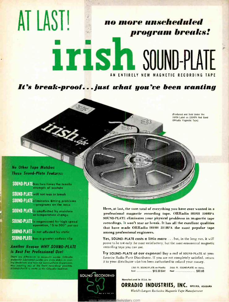
AT LAST! no more unscheduled program breaks:
Irish SOUND -PLATE AN ENTIRELY NEW MAGNETIC RECORDING TAPE
It's break - proof... just what you've been wanting
(Produced and Sold Under the IRISH Label as 22ORPA Red Band
ORRadio Magnetic Tape)
No Other Tape Matches
These Sound -Plate Featars.s:
SOUND -PLA
SOUND -PLA
SOUND -PLATE
SOUND -PLATE
SOUND -PLA
SOUND -PLA
UND -P
has two times the tensile strength of acetate
I not teat or break
ates limirg problems -programs on the nose
affected by moisture emperat.Lre change
J,is engineered fc r high speed operation, ' 5 to 500" per sec
:is not affected by static
has a greater surface slip
Anot ` Reason WHY SOUND -PLATE is Best For Professional Use! There are differences in magneti: oxides. ORRadio molecular lubricated oxides ore more stable in coat- ing conditions and turn out more i.niform dispersions, thus assuring you of the finest recordings possible. SOUND -PLATE is made in the ORtadio tradition
Here, at last, the sum total of everything you have ever wanted in a professional magnetic recording tape. ORRadio IRISH 22ORPA
SOUND -PLATE eliminates your physical problems in magnetic tape recordings. It won't tear or break. It has all the excellent qualities that have made ORRadio IRISH IIIRPA the most popular tape among professional engineers.
Yes, SOUND -PLATE costs a little more ... but, in the long run, it will prove to be not only he most satisfactory, but the most economical magnetic recording tape you can use.
Try SOUND -PLATE at our expense! Buy a reel of SOUND- PLATE at your favorite Radio Parts Distributor. If you are not completely satisfied, return it to your distributor who has been authorized to refund your money.
SOUND RECORDING
1200 Ft. SOUND -PLATE on Plastic 2400 Ft. SOUND -PLATE on Meta.
Reel $15.50 List
Manufactsred in U.S.A. by
Reel $33.85
ORRADIO INDUSTRIES, INC. OPELIKA, ALABAMA
U'orld's Largest Exclusive Magnetic Tape Manufacturer
www.americanradiohistory.comAmericanRadioHistory.Com
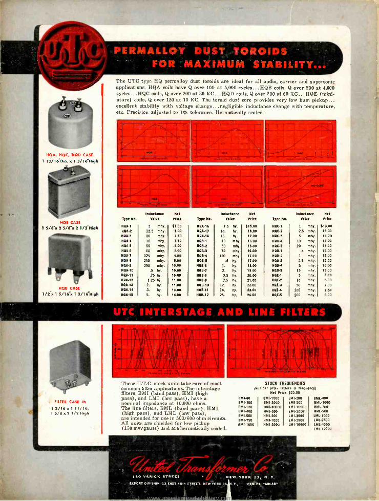
HOA, HOC, HOD CASE
1 13/16 -Dia. x 1 3/16 "High
HOB CASE
1 5/ex 2 5 /8 "x 2 1/2 High
HOE CASE
1/2 "x 1 5/16"x 1 3 /16High
The UTC type HQ permalloy dust toroids are ideal for all audio, carrier and supersonic applications. HQA coils have Q over 100 at 5,000 cycles... HQB coils, Q over 200 at 4,000 cycles... HQC coils, Q over 200 at 30 KC... HQD coils, Q over 200 at 60 KC... HQE (mini- ature) coils, Q over 120 at 10 KC. The toroid dust core provides very low hum pickup... excellent stability with voltage change...negligible inductance change with temperature, etc. Precision adjusted to 1% tolerance. Hermetically sealed.
Inductance Type No. Value
HQA-1
HQA-2
H QA-3
HQA-4
HQA-5
HQA-6
HQA-7
HOA-e
HQA-9
HQA-10
HQA-11
HQA-12
HOA-13
HOA-14
HQA-15
5 mhy.
12.5 mhy.
20 mhy.
30 mhy.
50 mhy.
80 mhy.
125 mhy.
200 mhy. 300 mhy.
-5 hy.
.75 hy.
1.25 hy.
2. hy.
3. hy.
5. hy.
Net
Price
$ 7.00
7.00
7.50
7.50
8.00
8.00
9.00
9.00
10.00
10.00 10.00
11.00
11.00
13.00
14.00
Type Ne.
HQA -16
HOA -17
HQA -18
HOB -1
HOB -2
HOB -3
H08 -4
HDB -5
HOB -6
HQB -7
HOB -8
HOB -9
HOB -10
HQB -11
HOB -12
7.5
10.
15.
10
30
70
120
.5
1-
2.
3.5 7.5
12.
18.
25.
Inductance Net Value Price
hy.
hy.
hy.
mhy .
mhy .
mhy. mhy. hy. hy.
hy. hy.
hy. hy.
hy.
by.
$15.00 16.00 17.00 16.00
16.00 16.00 17.00 17.00 111.00
19.00
20.00 21.00 22.00 23.00 24.00
Inductance Net
Type No. Value Price
HOC -1
HOC -2
HOC -3
HOC -4
HOC -5
H00 -1
HDO -2
HDD -3
11110 -4
HOD -5
HQE -1
HQE -2
HQE-3
HOE-4
HOE -5
1
2.5
5
10
20
.4
1
2.5 5
15
5
10
50
100
200
mhy.
mhy.
mhy. mhy.
mhy. mhy. mhy. mhy. mhy. mhy. mhy. mhy. mhy.
mhy. mhy.
$13.00 13.00 13.00 13.00
13.00 15.00 15.00 15.00 15.00 15.00
6.00 6.00
7.00
7.50 8.00
g
' NITE R ° TuTornie
FILTER CASE M
1 3/ 1 6 x 1 1 1/16, 15/8 x 2 1/2 High
These U.T.C. stock units take care of most common filter applications. The interstage filters, BMI (band pass), HMI (high pass), and LMI (low pass), have a nominal impedance at 10,000 ohms. The line filters, BML (band pass), HML (high pass), and LML (low pass), are intended for use in 500/600 ohm circuits. All units are shielded for low pickup (150 my /gauss) and are hermetically sealed.
STOCK FREQUENCIES (N mber after letters is frequency)
Net Price $25.00 BM I-60 BMI-100 BM1.120 BM 1-400 BM I-500 BM I-750 BM I-1000
BMI.1500 BMI -3000 BM 1.10000 HMI -200 HM1.500 HMI -1000 HM 1.3000
LM I-200 LM I-500 lM1-1000 LMI-2000 LM 1.3000 LM 1-5000 LP/I-10000
BML-400 BML-1000 HML-200 HML-500 LML-1000 LML-2500 LML-4000 LML-12000
1 5 VARICK STREET % NEW YORK 13, N. Y.
EXPORT DIVISION: 13 EAST 40th STREET, NEW YORK 16 . Y., CABLES: "AREAS"
www.americanradiohistory.comAmericanRadioHistory.Com


![IVECO DAILY [2014+] VAN 30S-35S WB3520L-WB4100 VAN … fileIVECO DAILY [2014+] VAN 30S-35S WB3520L-WB4100 VAN 30S-35S WB4100, VAN 35C WB3520L VAN 35C WB4100-4100L VAN 40C-50C WB3520L](https://img.dokumen.tips/doc/110x75/5c67c8ec09d3f2ff5a8c70f8/iveco-daily-2014-van-30s-35s-wb3520l-wb4100-van-daily-2014-van-30s-35s-wb3520l-wb4100.jpg)