Embed Size (px)
Citation preview


Contents
Introduction iInspection iSafety Notes iiNotes on Use vi
Chapter 1 Outline 11.1 Product Outline 11.2 Features 21.3 Names and Functions of Parts 4
Chapter 2 Specifications 72.1 General Specifications 72.2 Measurement Range and Tolerances 9
Chapter 3 Technical Information 113.1 Earthing Resistance 113.2 Measurement Principle 13
Chapter 4 Measurement Procedure 154.1 Preparations 164.2 Normal Measurement (3-Pole Method) 174.3 Simplified Measurement (2-Pole Method) 224.4 Using the Earthing Net 284.5 Measurement Precautions and Hints 29
Chapter 5 Maintenance and Service 355.1 Attaching the Hand Strap 355.2 Changing the Batteries 365.3 Cleaning the Unit 385.4 Service 38


i―――――――――――――――――――――――――――
Introduction――――――――――――――――――――――――
Introduction
Inspection
Thank you for purchasing the HIOKI"3151EARTH HiTESTER." To obtain maximumperformance from the instrument, please readthis manual first, and keep it handy for futurereference.
When you receive the instrument, inspect itcarefully to ensure that no damage occurredduring shipping. In particular, check theaccessories, panel switches, and connectors. Ifdamage is evident, or if it fails to operateaccording to the specifications, contact yourdealer or Hioki representative.
Accessories9214 AUXILIARY EARTHING RODS (two)9215 MEASURING CABLE
(black 5 m, yellow 10 m, red 20 m)9216 CABLE WINDER (with 9215) (three)9393 CARRYING CASEHand strapInstruction manualR6P Manganese batteries (six)

ii―――――――――――――――――――――――――――
Safety Notes――――――――――――――――――――――――
DANGER
This instrument is designed to comply with IEC61010 Safety Standards, and has been thoroughlytested for safety prior to shipment. However,mishandling during use could result in injury ordeath, as well as damage to the instrument. Becertain that you understand the instructions andprecautions in the manual before use. Wedisclaim any responsibility for accidents orinjuries not resulting directly from instrumentdefects.
Safety Notes
This manual contains information andwarnings essential for safe operation of theinstrument and for maintaining it in safeoperating condition. Before using theinstrument, be sure to carefully read thefollowing safety notes.

iii―――――――――――――――――――――――――――
Safety Notes――――――――――――――――――――――――
The symbol printed on theinstrument indicates that the usershould refer to a corresponding topic inthe manual (marked with thesymbol) before using the relevantfunction.In the manual, the symbol indicatesparticularly important information thatthe user should read before using theinstrument.
Indicates a double-insulated device.
Indicates AC (Alternating Current).
DANGER
Indicates that incorrect operationpresents an extreme hazard that couldresult in serious injury or death to theuser.
WARNING
Indicates that incorrect operationpresents a significant hazard that couldresult in serious injury or death to theuse.
CAUTIONIndicates that incorrect operationpresents a possibility of injury to theuser or damage to the instrument.
NOTEIndicates advisory items related toperformance or correct operation of theinstrument.
Safety Symbols
The following symbols in this manual indicatethe relative importance of cautions and warnings.

iv―――――――――――――――――――――――――――
Safety Notes――――――――――――――――――――――――
Overvoltage categories (CAT)
This instrument complies with CAT II safetyrequirements.To ensure safe operation of measurementinstruments, IEC 60664 establishes safetystandards for various electrical environments,categorized as CAT I to CAT IV, and calledovervoltage categories. These are defined asfollows.CAT I : Secondary electrical circuits
connected to an AC electrical outletthrough a transformer or similardevice.
CAT II : Primary electrical circuits inequipment connected to an ACelectrical outlet by a power cord(portable tools, household appliances,etc.)
CAT III : Primary electrical circuits of heavyequipment (fixed installations)connected directly to the distributionpanel, and feeders from thedistribution panel to outlets.
CAT IV : The circuit from the service drop tothe service entrance, and to thepower meter and primary overcurrentprotection device (distribution panel).

v―――――――――――――――――――――――――――
Safety Notes――――――――――――――――――――――――
Higher-numbered categories correspond toelectrical environments with greater momentaryenergy. So a measurement device designed forCAT III environments can endure greatermomentary energy than a device designed forCAT II.Using a measurement instrument in anenvironment designated with a higher-numbered category than that for which theinstrument is rated could result in a severeaccident, and must be carefully avoided.

vi―――――――――――――――――――――――――――
Notes on Use――――――――――――――――――――――――
DANGER
When measuring earthing resistance, a voltageof maximum 50 Vrms exists across themeasurement terminals E - C(H). Take properprecautions against electric shock.When performing a simplified measurement (2-pole method) with the instrument connected tothe earth side of a household power supply (ACoutlet), take proper precautions against electricshock.
Notes on Use
Follow these precautions to ensure safeoperation and to obtain the full benefits of thevarious functions.

vii―――――――――――――――――――――――――――
Notes on Use――――――――――――――――――――――――
WARNING
Do not allow the instrument to get wet, and donot take measurements with wet hands. This maycause an electric shock. Take appropriate carewhen using the instrument outdoors.Do not use the instrument where it may beexposed to corrosive or combustible gases. Theinstrument may be damaged or cause anexplosion.Do not power the instrument from sources otherthan batteries, to prevent damage and the risk ofelectric shock.Before using the instrument, make sure that theinsulation on the measuring cable is undamagedand that no bare conductors are improperlyexposed. Using the instrument in such conditionscould cause an electric shock, so contact yourdealer or Hioki representative for replacements.(Model 9215).

viii―――――――――――――――――――――――――――
Notes on Use――――――――――――――――――――――――
CAUTION
Do not store or use the instrument where it couldbe exposed to direct sunlight, high temperature orhumidity, or condensation. Under such conditions,the instrument may be damaged and insulationmay deteriorate so that it no longer meetsspecifications.Although this instrument is dust resistant, it is notcompletely dust- or waterproof. To prevent possibledamage, avoid using in dusty or wet environments.To avoid damage to the instrument, protect it fromphysical shock when transporting and handling. Beespecially careful to avoid physical shock fromdropping.

1―――――――――――――――――――――――――――
Chapter 1 Outline――――――――――――――――――――――――
Chapter 1Outline
1.1 Product Outline
The earthing (grounding) of electricalequipment is essential in maintaining safetyand protecting lives, as well as preventingdamage to equipment.This instrument uses the AC phase differentialsystem to measure earthing resistance. Thisassures accurate measurements unaffected byearth voltage and auxiliary earthing resistance.

2―――――――――――――――――――――――――――
Chapter 1 Outline――――――――――――――――――――――――
1.2 Features(1) High performance
Performance of this instrument surpasses therequirements of the Japanese standard JISC-1304-1995 and complies with the safetystandard IEC 61010.
(2) Wide measurement range
Measurement scope was extended to 115% ofthe earthing resistance measurement range.This is useful especially in the 10 Ω and100 Ω measurement modes which areimportant for earthing evaluation duringelectrical installation work.
(3) Auxiliary earthing resistance check function
Auxiliary earthing resistance can be checkedfor each pole, in order to evaluate possibleinfluences upon the measurement.
(4) Switchable measurement frequency
Measurement frequency can be changed by theuser, to minimize the influence of harmonicearth voltage and to assure stablemeasurement.
(5) Simplified measurement function
Simplified earthing resistance measurement ispossible using the earth of an AC outlet.

3―――――――――――――――――――――――――――
Chapter 1 Outline――――――――――――――――――――――――
(6) Over-voltage protection and warning buzzer
When an AC outlet is used for simplifiedmeasurement and a voltage is input bymistake, the protection circuit is activated anda warning tone is heard.
(7) Semi-dust-proof construction
Measurement switches, indicators and othermoving parts are designed to withstand use intough environments.
(8) Easy to use
The supplied carrying case is designed to holdthe instrument and all accessories. A cablewinder is standard, making it easy to deployand store measurement leads.

4―――――――――――――――――――――――――――
Chapter 1 Outline――――――――――――――――――――――――
Front View1 2
3
4
5678
9
10
11 12 1314
1.3 Names and Functions of Parts
① Measurement button (PRESS ON)
Press this button for earthing resistancemeasurement, auxiliary earthing resistancecheck, and battery check.
② Range selector
Serves to switch the instrument to batterycheck, earth voltage measurement, auxiliaryearthing resistance check, and earthingresistance measurement.
③ 2/3 pole measurement selector (TERMINALS)
Serves to switch between 2-pole measurement(simplified measurement) and 3-polemeasurement. Also serves to switch themeasurement frequency (a/b) to reduce theinfluence of harmonic earth voltage.

5―――――――――――――――――――――――――――
Chapter 1 Outline――――――――――――――――――――――――
④ Resistance dial
The measured resistance value can be readfrom this dial.
⑤ Dial knob
⑥ Galvanometer
⑦ Battery effective range
⑧ Auxiliary earthing resistance effective range
⑨ Earth voltage scale
⑩ ADJUST: Zero adjustment
⑪ E: Earth terminal
This terminal is to be connected to the earth ofthe measurement object.
⑫ P (S): Probe terminal
Terminal for potential detection
⑬ C (H): Auxiliary earthing terminal
This terminal supplies measurement current.
⑭ Explanation label
Contains brief instructions and instrumentspecifications.

6―――――――――――――――――――――――――――
Chapter 1 Outline――――――――――――――――――――――――
Rear View15
16
⑮ Fixing screw on the battery cover
⑯ Battery cover

7―――――――――――――――――――――――――――
Chapter 2 Specifications――――――――――――――――――――――――
Operating system AC potentiometer
Display Method Resistance indication on meter withlinear scale galvanometer
Open circuit voltage 50 V AC max
Measurement current 15 mA AC max (using the 2-polemethod: 3 mA AC max)
Measurementfrequency
575 Hz (during setting to 2a or 3a)600 Hz (during setting to 2b or 3b)
Operatingtemperature andhumidity range
0 to 40 (32 to 104 ),80% RH or less (with no condensation)
Storage temperatureand humidity range
-10 to 50 (14 to 122 ),80% RH or less (with no condensation)
Usage range Instrument is designed for earthingresistance measurements in locations up toa height of 3,000 meters (except farms)
Power supply Six R6P manganese batteries orsix LR6 alkaline batteriesRated supply voltage: 1.5 V x 6
Maximum ratedpower
2.5 VA max
Chapter 2Specifications
2.1 General Specifications

8―――――――――――――――――――――――――――
Chapter 2 Specifications――――――――――――――――――――――――
Battery Life More than 500 times (R6P in use) ormore than 1400 (LR6 in use)(30-second measurement/30-secondpause cycle)
Overvoltageprotection
250 VAC for one minutebetween E-P (S) and E-C (H) terminals
Insulation resistance 100 MΩ or more/500 V DCbetween electric circuit and case
Dielectric voltage 3000 V AC for one minutebetween electric circuit and case
External dimensions Approx. 164W x 119H x 88D mm(6.46W" x 4.37H" x 3.47D")(excluding protrusion)
Mass Approx. 800 g (28.2oz.) (instrument only)
Accessories 9214 AUXILIARY EARTHING ROD9215 MEASURING CABLE
(black 5m, yellow 10 m,red 20 m each one,9216 CABLE WINDER x 3)
9393 CARRYING CASER6P manganese battery x 6Instruction manual, Hand strap
Option 9050 EARTH NETS 30 x 30cm
Standards applyingEarthing resistance
measurementSafety
EMCEnvironment
protection
JIS C1304-1995EN61557-5:1997JIS C1004-1996EN61010-1:2001Pollution Degree 2, MeasurementCategory II (anticipated transientovervoltage 500 V)EN61010-2-031:1994EN61326:1997+A1:1998+A2:2001EN60529:1991 "IP40"JIS C920-1993

9―――――――――――――――――――――――――――
Chapter 2 Specifications――――――――――――――――――――――――
Accuracy is guaranteed for 1 year at following conditions.(Temperature and humidity: 23 5 (73 5 ), 80%RH or less)
Measurementitem
Measurement range Tolerances
Earthingresistance
(Ω)
10 (0 to 11.5)100 (0 to 115)
1000 (0 to 1150)2.5%f.s.
Earth voltage (V) 30 (0 to 30) 3.0%f.s.
When using 2-pole method, applies 100 Ω and 1000 Ω only
Effect of temperature Within 0.1%/at 0 to 40 (32 to 104 )
Effect of auxiliaryearth resistance
Within 5% when fluctuation is0 to 5 kΩ
Effect of earthvoltage
Within 2% at 0 to 5 VWithin 2% at 0 to 10 V(at 50 or 60 Hz)Within 5% at 0 to 3 V(at DC, 16 2/3, 400 Hz)
Effect of powervoltage Within specifications for 6 - 10 V DC
Effect of radiatedradio-frequencyelectromagnetic field
At 3 V/mWithin +2.5%f.s. to -40%f.s.(earthing resistance)
2.2 Measurement Range andTolerances

10―――――――――――――――――――――――――――
Chapter 2 Specifications――――――――――――――――――――――――
Intrinsic error /influence quantity 1 2 3 4
Intrinsic error 2.5% A Reference conditions Part 5, 6.1
Position 5.0% E1Reference position 90
°Part 1, 4.2
Supplyvoltage 0.0% E2
At the limits statedby the manufacturer
Part 1, 4.2,4.3
Temperature 2.3% E3 0 and 35 Part 1, 4.2
Seriesinterferencevoltage
5.0% E4 See 4.2 and 4.3 Part 5, 4.2,4.3
Resistance ofthe probesand auxiliaryearthelectrodes
5.0% E50 to 100 x RAbut ≦50 kΩby PC check
Part 5, 4.3
Systemfrequency __ E7
99% to 101% of thenominal frequency Part 5, 4.3
Systemvoltage __ E8
85% to 110% of thenominal frequency Part 5, 4.3
1: Error2: Designation code3: Reference conditions or specified operating range4: Requirements or test in accordance with the relevant parts of
EN61557
Operating error(according to EN61557-5, 4.3:1997)The operating error is calculated by thefollowing combination of the values ofinfluence quantity in the operating range.
Operating error
= 12.8%

11―――――――――――――――――――――――――――
Chapter 3 Technical Information――――――――――――――――――――――――
Chapter 3Technical Information
3.1 Earthing Resistance
Earthing resistance measurements differ fromordinary resistance measurements, due to thefactors described below.
(1) Polarization
Because of polarization between the earthingbody and the earth ground, using a directcurrent for measurement is not possible.
(2) Special conditions
Because one pole of the earth resistancemeasurement object is buried in the ground, itcannot be taken out for measurement. Also,because the earthing resistance is a spreadingresistance from the earthing body, it isnecessary to use the 3-pole measurementmethod with sufficient distance between themeasuring electrodes.

12―――――――――――――――――――――――――――
Chapter 3 Technical Information――――――――――――――――――――――――
(3) External noise
When measuring earthing resistance, leakagecurrent from connected equipment, earthvoltage caused by earth current, and auxiliaryearthing resistance can affect the measurementand cause erroneous readings.To eliminate such influences as much aspossible, the 3151 uses a newly developed ACphase differential method to measure earthingresistance. This assures accurate results alsounder difficult conditions.

13―――――――――――――――――――――――――――
Chapter 3 Technical Information――――――――――――――――――――――――
Rs
S
Galvanometer
P(S)E C(H)
RcRx Rp
IC.T.1 : n
OscillatorSynchronous
rectifier
Figure 1 Measurement Principle (3-pole method)
3.2 Measurement Principle(1) Normal measurement (3-pole method)
Figure 1 shows the basic circuit principle forearthing resistance measurement. Themeasuring current I, driven by the oscillatingvoltage of the oscillator, flows through the loopformed as follows: oscillator→Rc→Rx→C.T.If the galvanometer is balanced, the voltagebetween the measurement terminals E - P(S) istaken as Ex, and the resistance between themeasurement terminal E and the slider S of thevariable resistor is taken as Rs. The voltagedrop at the variable resistor is Es.The following equations then apply:Ex = IRx, Es = IRs/n (n: C.T. winding ratio)Ex = Es, therefore Rx = Rs/n
If the dial connected directly to the slidingresistor has a scale of 1/n for Rs, the dial readingcorresponds to the earthing resistance Rx.

14―――――――――――――――――――――――――――
Chapter 3 Technical Information――――――――――――――――――――――――
I
S
Galvanometer
Rs
P(S)E C(H)
RoRx
C.T.1 : n
OscillatorSynchronous
rectifier
Figure 2 Measurement Principle (2-pole method)
(2) Simplified measurement (2-pole method)
Figure 2 shows the basic circuit principle for asimplified earthing resistance measurementusing an existing earthing body.If the earthing resistance of the existingearthing body is taken as Ro and the earthingresistance of the measurement object as Rx, thesame equation as for the 3-pole methodapplies:Rx + Ro = Rs/n
Therefore, the earthing resistance can be foundby adding the earthing resistance of theexisting earthing body (Ro) to the earthingresistance of the measurement object (Rx).The 3151 uses a very low measurementcurrent, so that the leakage current circuitbreaker of a household power supply will notbe tripped when the grounded side of an ACoutlet is used as existing earthing body.

15―――――――――――――――――――――――――――
Chapter 4 Measurement Procedure――――――――――――――――――――――――
WARNING
When the measurement button (PRESS ON) isoperated, a voltage of maximum 50 Vrms AC isproduced. Take proper precautions againstelectric shock.When using the grounded side of an AC outletfor simplified measurement, be sure to checkthe outlet first, to determine the grounded side.Use a suitable checker (electroscope or similar)for this purpose. Take proper precautionsagainst electric shock.
CAUTION
If the batteries are exhausted, the warning tone willnot sound also when a voltage is applied due to awrong connection. Always check the batteries beforestarting to use the instrument.
Chapter 4Measurement
Procedure

16―――――――――――――――――――――――――――
Chapter 4 Measurement Procedure――――――――――――――――――――――――
4.1 Preparations
(1) Zero adjustment
Before use, adjust the needle of thegalvanometer to the zero point.Use a small flat-blade screwdriver to turn theADJUST control until the needle points at thecenter of the scale.This must be performed while the measurementbutton (PRESS ON) is not depressed.
(2) Battery check
Perform a battery check to verify that thebatteries are still good. If exhausted, replacethe batteries with fresh ones. (See Section 5.2.)

17―――――――――――――――――――――――――――
Chapter 4 Measurement Procedure――――――――――――――――――――――――
Measurement terminal Lead Object to be connected
E black Measurement object EP (S) yellow Auxiliary earthing rods PC (H) red Auxiliary earthing rods C
Figure 3 Normal Measurement Connection
C P E E
Rx
5-10 m 5-10 m
P C
NOTE
4.2 Normal Measurement (3-PoleMethod)(1) Connections
Connect the measurement terminals to themeasurement object using the suppliedmeasurement leads, as shown in Figure 3.Drive the auxiliary earthing rods P and C deepinto the ground, at intervals of 5 - 10 meters(straight line) from the measurement object E.
The ground into which the auxiliary earthingrods are driven should be as humid aspossible. If the rods cannot be driven into theground, such as on concrete surfaces, use the9050 EARTH NETS available as an option.(See Section 4.4)

18―――――――――――――――――――――――――――
Chapter 4 Measurement Procedure――――――――――――――――――――――――
NOTE
NOTE
(2) Settings for 3-pole measurement
Set the 2/3 pole measurement selector(TERMINALS) to "3a".
When using the 3-pole measurement method,measurement can be carried out with ameasurement frequency of 575 Hz (3a) or 600Hz (3b). Normally, you should choose the "3a"setting. If the galvanometer fluctuates duringmeasurement, try choosing the "3b" setting.This reduces the influence of harmonics earthvoltage and other extraneous earth voltagecomponents.
(3) Battery check
Set the range selector to and press themeasurement button (PRESS ON). If the needleof the galvanometer is within the rangeof the scale, the batteries can be used formeasurement. Perform this check in the actualmeasurement condition, with the measurementleads already connected.
If the needle of the galvanometer is not withinthe "BATT" range of the scale, the batteriesmust be replaced. (See Section 5.2)

19―――――――――――――――――――――――――――
Chapter 4 Measurement Procedure――――――――――――――――――――――――
CAUTION
If the measurement button (PRESS ON) isdepressed, earth voltage cannot be measured. Theneedle of the galvanometer may fluctuate orregister to the end of the scale. This is not a defect.If there is an earth voltage of more than 10 V, theearthing body should be isolated from the electricalinstallation and power line switches or similarshould be turned off in order to minimize the earthvoltage for measurement. Also, if the earth voltageis high, a risk of electric shock exists and properprecautions should be taken.
(4) Earth voltage check
Set the range selector to V to check for thepresence of earth voltage. Do not press themeasurement button (PRESS ON) at this time.
(5) Auxiliary earthing resistance check
The 3151 has a function for checking theauxiliary earthing resistance. Be sure toperform this check before measuring earthingresistance.The check result should be evaluated asfollows: The more the needle of thegalvanometer deflects to the left, the higher isthe auxiliary earthing resistance. (If the needleremains in the vicinity of the zero point,auxiliary earthing resistance poses noproblem.)

20―――――――――――――――――――――――――――
Chapter 4 Measurement Procedure――――――――――――――――――――――――
NOTE
① Checking earthing condition of auxiliaryearthing rod C
Set the range selector to C and press themeasurement button (PRESS ON). Verify thatthe needle of the galvanometer is within thegreen "P/C CHECK" range.
② Checking earthing condition of auxiliaryearthing rod P
Set the range selector to P and press themeasurement button (PRESS ON). Verify thatthe needle of the galvanometer is within thegreen "P/C CHECK" range.
If the needle of the galvanometer is notwithin the green range, the earthingresistance of the auxiliary earthing rod is toohigh and accurate measurement results willnot be obtained.Change the position of the rod, and/or makesure that the ground has sufficient humidity(pour water if necessary). Then repeat thecheck.If the 2/3 pole measurement selector(TERMINALS) is set to "2a" or "2b", the checkwill not give correct results.

21―――――――――――――――――――――――――――
Chapter 4 Measurement Procedure――――――――――――――――――――――――
NOTE
(6) Earthing resistance measurement
Set the range selector to a suitable position( x 1 Ω, x 10 Ω, x 100 Ω) and press themeasurement button (PRESS ON). Whilekeeping the button depressed, turn the dialknob until the galvanometer is balanced.(until the needle points at the center of thescale.)Then read the indication on the resistance dialand multiply it with the setting of the rangeselector. The result is the earthing resistance.
In general, you should first choose thex 100 Ω setting of the range selector and
then reduce the setting as necessary.If the 2/3 pole measurement selector(TERMINALS) is set to "2a" or "2b", correctmeasurement is not possible.Balancing the galvanometer is invalid whereno scale on the resistance dial.

22―――――――――――――――――――――――――――
Chapter 4 Measurement Procedure――――――――――――――――――――――――
DANGER
When using the grounded side of an AC outlet forsimplified measurement, be sure to check theoutlet first, to determine the grounded side. Use asuitable checker (electroscope or similar) for thispurpose.Take proper precautions against electric shock.If the 3151 is connected by mistake to the live(hot) side of an outlet and a voltage of 80 V ormore is applied to the input, a warning tone(beep) is heard.In this case, immediately disconnect the leadsand check the outlet again.
CAUTION
The warning tone will not sound if the earthing bodyis not connected to terminal E. Connect terminal Efirst. When the connection is made by mistake on thepower line with the leakage current circuit breaker,the breaker may be tripped before the beep sounds.
4.3 Simplified Measurement (2-PoleMethod)

23―――――――――――――――――――――――――――
Chapter 4 Measurement Procedure――――――――――――――――――――――――
NOTE
The simplified measurement (2-pole method)makes use of an existing earthing body.It should only be used in cases where theauxiliary earthing rods cannot be driven intothe ground.The existing earthing body must have asufficiently lower resistance than the earthingbody to be measured.When the 2-pole method is used, themeasurement current of the 3151 is kept to 3mA or less, so that the leakage current circuitbreaker of a household power supply will notbe tripped when the grounded side of an ACoutlet is used as an existing earthing body.
When using the simplified measurementmethod, the resistance of the existing earthingbody is added to the measurement result.For measurements in the range of 10 Ω andbelow, you should always use the normalmeasurement (3-pole method).

24―――――――――――――――――――――――――――
Chapter 4 Measurement Procedure――――――――――――――――――――――――
Measurement terminal Lead Connection
E black Measurement object EP (S) Not connectedC (H) red/yellow Ground line (Ro)
Figure 4 Simplified Measurement Connection
P S 250 VAC max
Rx
E C
R0
At least 5 m
NOTE
(1) Connections
Figure 4 shows connection for a simplifiedmeasurement using the grounded side of ahousehold power supply (AC outlet).Use the supplied measurement leads to makeconnections as shown in the illustration.Set the range switch to or V, connectterminal E to the measurement object E, andthen connect terminal C (H) to the groundedside of the AC outlet.
A metal water pipe or similar can also be usedas existing earthing body for simplifiedmeasurement.The distance between the existing earthingbody and the measurement object should be atleast 5 meters. If the distance is less, correctresults will not be obtained.

25―――――――――――――――――――――――――――
Chapter 4 Measurement Procedure――――――――――――――――――――――――
NOTE
NOTE
(2) Settings for 2-pole measurement
Set the 2/3 pole measurement selector(TERMINALS) to "2a".
When using the 2-pole measurement method,measurement can be carried out with ameasurement frequency of 575 Hz (2a) or 600Hz (2b). Normally, you should choose the "2a"setting. If the galvanometer fluctuates duringmeasurement, try choosing the "2b" setting.This reduces the influence of harmonics earthvoltage and other extraneous earth voltagecomponents.
(3) Battery check
Set the range selector to and press themeasurement button (PRESS ON). If the needleof the galvanometer is within the rangeof the scale, the batteries can be used formeasurement. Perform this check in the actualmeasurement condition, with the measurementleads already connected.
If the needle of the galvanometer is not withinthe "BATT" range of the scale, the batteriesmust be replaced. (See Section 5.2)

26―――――――――――――――――――――――――――
Chapter 4 Measurement Procedure――――――――――――――――――――――――
CAUTION
If the measurement button (PRESS ON) isdepressed, earth voltage cannot be measured. Theneedle of the galvanometer may fluctuate orregister to the end of the scale. This is not a defect.If there is an earth voltage of more than 10 V, theearthing body should be isolated from the electricalinstallation and power line switches or similarshould be turned off in order to minimize the earthvoltage for measurement. Also, if the earth voltageis high, a risk of electric shock exists and properprecautions should be taken.
NOTE
(4) Earth voltage check
Set the range selector to V to check for thepresence of earth voltage. Do not press themeasurement button (PRESS ON) at this time.
(5) Auxiliary earthing resistance check
Auxiliary earthing resistance check is notrequired.
When the function P or C is selected and themeasurement button (PRESS ON) is pressed,the needle of the galvanometer may fluctuateor register to the end of the scale. This is not adefect, but the check result is invalid.

27―――――――――――――――――――――――――――
Chapter 4 Measurement Procedure――――――――――――――――――――――――
NOTE
(6) Earthing resistance measurement
Set the function switch to a suitable position (x 10 Ω, x 100 Ω) and press the measurementbutton (PRESS ON).While keeping the button depressed, turn thedial knob until the galvanometer is balanced.Then read the indication on the resistance dialand multiply it with the setting of the rangeselector. The result is the earthing resistance.Measurement result = Rx + Ro (combinedresistance)
In general, you should first choose thex 100 Ω setting of the range selector and
then reduce the setting as necessary.If the 2/3 pole measurement selector(TERMINALS) is set to "3a" or "3b", correctmeasurement is not possible. Since themeasurement current will be higher in aposition for 3-pole measurement, the leakagecurrent circuit breaker of a household powersupply may be tripped.Balancing the galvanometer is invalid whereno scale on the resistance dial.

28―――――――――――――――――――――――――――
Chapter 4 Measurement Procedure――――――――――――――――――――――――
NOTE
4.4 Using the Earthing NetIf auxiliary earthing rods cannot be driven intothe ground, such as on rock, gravel, orconcrete, use the earthing net available as anoption.
1. Place the grid flat on the ground, and pour asufficient amount of water on it to ensure goodsurface contact.
2. Connect the measurement leads as shown inthe illustration, using a clip to connect the leaddirectly to the grid or placing the auxiliaryearthing rod on the grid.
3. Set the range selector to the "P, C" range,verify that the grid has good contact, andperform the measurement.
On surfaces such as asphalt or similar wherewater will not permeate the ground,measurement with the earthing net is notpossible.If the earthing net is not available or if it is toosmall, a metal plate or other conducting objectcan be used as a substitute, provided that it iswatered sufficiently.

29―――――――――――――――――――――――――――
Chapter 4 Measurement Procedure――――――――――――――――――――――――
4.5 Measurement Precautions andHints(1) Using the auxiliary earthing rods
For 3-pole measurement, two auxiliary earthingrods are required. Be sure to drive the rodswell into the ground to assure correctmeasurement results.
(2) Earthing resistance of auxiliary earthing rods
When the earthing resistance of the auxiliaryearthing rods is not higher than about 10 kΩ,the 3151 can carry out correct measurement.However, especially when measuring lowearthing resistance values, high earthingresistance of the auxiliary earthing rods canimpair measurement sensitivity.To assure correct measurement results, be sureto check the earthing resistance of the auxiliaryearthing rods by setting the range selector to Cand P.If the needle of the galvanometer is whithin agreen band of the scale, the auxiliary earthingresistance is within 5 kΩ.

30―――――――――――――――――――――――――――
Chapter 4 Measurement Procedure――――――――――――――――――――――――
If check results are unsatisfactory:
① Drive the auxiliary earthing rods deep into theground and water the entire area with asufficient amount of water. Watering is usuallyvery effective in reducing the contactresistance.
② Change the location of the auxiliary earthingrods. Choose a location with high humidity.
If the ground is volcanic rock or sand, thesupplied auxiliary earthing rods may not besufficient. In such a case, use a metal pipe orother conductive object with a large surfaceand bury it as deep as possible in the ground.
(3) Distance between earthing electrodes
As shown in the figure (a) on the next page,when the distance between E and C is l m, andthe distance between the E and P electrodes isvaried (x m), the resistance of the earthingbody E will measure as shown in the figure(b).Therefore, when the position of the auxiliaryearthing rod P is closer to the earthing body Eor the auxiliary earthing rod C, a measurementerror occurs.

31―――――――――――――――――――――――――――
Chapter 4 Measurement Procedure――――――――――――――――――――――――
PE
Resistance rangeof electrode E
Resistance rangeof electrode C
Horizontalsection
C
Rx
x ml m
Measurementvalue
x m l m
Rc
Earth surface
(b)(a)
When the distance between the electrodes E -C is small, the earthing resistance of themeasurement object (Rx) and the auxiliaryearthing rods cannot be separated, leading to ameasurement error.In the case of an architectural structure whichis grounded over a large area, the resistancerange of the earthing resistance (Rx) in thefigure (a) becomes very wide. This means thatit is necessary to position the auxiliary earthingrods (P and C) at a sufficiently large distancefrom the earthing body (Rx).To determine the proper distance, move theauxiliary earthing rod P towards the auxiliaryearthing rod C and perform measurement atseveral points. Check whether there is an areawhere the measured resistance remainsapproximately constant also when the auxiliaryearthing rod P is moved. This corresponds tothe horizontal section in the figure (b).If such an area cannot be found, themeasurement distance is not sufficient, and theauxiliary earthing rods P and C should bemoved further away from measurement object.

32―――――――――――――――――――――――――――
Chapter 4 Measurement Procedure――――――――――――――――――――――――
29°5 m 5 m
E P C
(4) Position relationship of auxiliary earthingrods
The auxiliary earthing rod P should normallybe positioned halfway on a straight linebetween the earthing body E and the auxiliaryearthing rod C. If this is not possible due toobstacles or the like, the area within a radiusof 5 meters from the earthing body E and theauxiliary earthing rod C should be avoided,and the auxiliary earthing rod P should bepositioned on a line not diverging more than29 degrees from the line between the earthingbody E and the auxiliary earthing rod C. Thiswill help to reduce measurement errors.

33―――――――――――――――――――――――――――
Chapter 4 Measurement Procedure――――――――――――――――――――――――
(5) Influence of earth voltage
Due to the presence of leakage current fromelectrical equipment connected to the earthingbody or of earth current, a voltage may exist atthe earthing body. If the voltage is less thanabout 10 V, it will normally not affect theearthing resistance measurement. However, ifthe earth voltage is distorted, it may causemeasurement errors even at lower voltagelevels. For this reason, if an earth voltage ofmore than about 5 V is detected, otherelectrical equipment should be switched off orthe equipment should be disconnected toeliminate the influence of earth voltage on themeasurement.During simplified measurement, harmonicleakage current in the ground line can causethe galvanometer to fluctuate. In such a case,change the setting of the 2/3 pole measurementselector (TERMINALS) from "2a" to "2b" (from"3a" to "3b" for normal measurement). Thismay allow stable measurement.If earth voltage is high, the insulation of theelectrical path or electrical equipment mayhave deteriorated. Check the insulation andperform a leakage current test.

34―――――――――――――――――――――――――――
Chapter 4 Measurement Procedure――――――――――――――――――――――――
(6) Other points
If the measurement button (PRESS ON) isoperated while nothing is connected to themeasurement terminals, the galvanometer mayregister to the end of the scale. This is not adefect.When the measurement button (PRESS ON) isoperated, a high-pitched tone will be heardfrom inside the instrument. This is caused bythe oscillator and is not a defect.
35―――――――――――――――――――――――――――
Chapter 5 Maintenance and Service――――――――――――――――――――――――
Chapter 5Maintenance and
Service
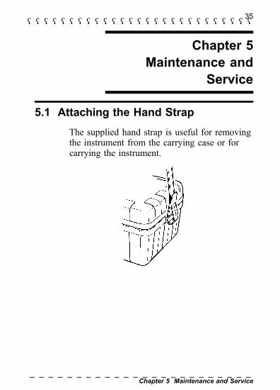
5.1 Attaching the Hand StrapThe supplied hand strap is useful for removingthe instrument from the carrying case or forcarrying the instrument.

36―――――――――――――――――――――――――――
Chapter 5 Maintenance and Service――――――――――――――――――――――――
WARNING
To avoid electric shock when replacing thebatteries, first disconnect the measuring cablefrom the object to be measured.After replacing the batteries, replace the coverand screws before using the instrument.To avoid the possibility of explosion, do notshort circuit, disassemble or incineratebatteries.Handle and dispose of batteries in accordancewith local regulations.
NOTE
5.2 Changing the Batteries
To avoid corrosion from battery leakage,remove the batteries from the instrument if it isto be stored for a long time.

37―――――――――――――――――――――――――――
Chapter 5 Maintenance and Service――――――――――――――――――――――――
A
B
1. For safety, disconnect the measurement leadsfrom the instrument.
2. Remove the fastening screw.
3. Remove the cover of the battery compartmentin direction A, as shown in the illustration.
4. Replace all six batteries with fresh ones.
5. Reattach the cover of the battery compartmentin direction B, as shown in the illustration.
6. Fasten the battery compartment cover to theinstrument with the fastening screw.

38―――――――――――――――――――――――――――
Chapter 5 Maintenance and Service――――――――――――――――――――――――
5.3 Cleaning the Unit
5.4 Service
After use, wipe the auxiliary earthing rods toremove mud and other contamination.Otherwise the rods may rust.To clean the instrument, wipe it gently with asoft cloth moistened with water or milddetergent. Never use solvents such as benzene,alcohol, acetone, ether, ketones, thinners orgasoline, as they can deform and discolor thecase.
If the instrument seems to be malfunctioning,confirm that the batteries are not discharged,and the measuring cable are not open circuitedbefore contacting your dealer or Hiokirepresentative.Pack the instrument carefully so that it willnot be damaged during shipment, and includea detailed written description of the problem.Hioki cannot be responsible for damage thatoccurs during shipment.


HIOKI 3151 EARTH HiTESTERInstruction Manual
Publication date: December 2003 Revised edition 6
Edited and published by HIOKI E.E. CORPORATIONTechnical Support SectionAll inquiries to Sales and Marketing InternationalDepartment81 Koizumi, Ueda, Nagano, 386-1192, JapanTEL: +81-268-28-0562 / FAX: +81-268-28-0568E-mail: [email protected] http://www.hioki.co.jp/
Printed in Japan 3151A980-06
All reasonable care has been taken in the productionof this manual, but if you find any points which areunclear or in error, please contact your supplier orthe International Sales and Marketing Department atHIOKI headquarters.In the interests of product development, the contentsof this manual are subject to revision without priornotice.Unauthorized reproduction or copying of this manualis prohibited.

HEAD OFFICE81 Koizumi, Ueda, Nagano 386-1192, JapanTEL +81-268-28-0562 / FAX +81-268-28-0568E-mail: [email protected] http: //WWW.hioki.co.jp
HIOKI USA CORPORATION6 Corporate Drive, Cranbury, NJ 08512, USATEL +1-609-409-9109 / FAX +1-609-409-9108
3151A980-06 03-12H
Printed on recycled paper


![[Ex 3151] Wiring Book](https://img.dokumen.tips/doc/110x75/56d6bf811a28ab30169680fc/ex-3151-wiring-book.jpg)