Embed Size (px)
Citation preview
311304J
Instructions - Parts List
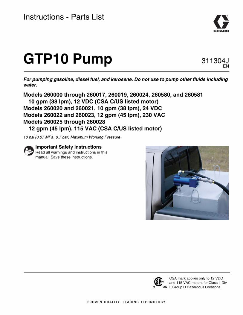
GTP10 PumpFor pumping gasoline, diesel fuel, and kerosene. Do not use to pump other fluids including water.
Models 260000 through 260017, 260019, 260024, 260580, and 26058110 gpm (38 lpm), 12 VDC (CSA C/US listed motor)
Models 260020 and 260021, 10 gpm (38 lpm), 24 VDCModels 260022 and 260023, 12 gpm (45 lpm), 230 VACModels 260025 through 260028
12 gpm (45 lpm), 115 VAC (CSA C/US listed motor)10 psi (0.07 MPa, 0.7 bar) Maximum Working Pressure
Important Safety InstructionsRead all warnings and instructions in this manual. Save these instructions.
CSA mark applies only to 12 VDC and 115 VAC motors for Class I, Div I, Group D Hazardous Locations
EN

Models
2 311304J
Models
Part No. Hose Nozzle
12 VDC, 10 gpm (38 lpm), 12.5 amps260000 260069 - 12 ft (3.66 m) grounded 260079 - manual, leaded/diesel
260001 260069 - 12 ft (3.66 m) grounded 260082 - automatic, regular/diesel
260002 260069 - 12 ft (3.66 m) grounded 260078 - manual, unleaded
260003 260069 - 12 ft (3.66 m) grounded 260083 - automatic, unleaded
260004 260526 - 4 ft (1.22 m) UL listed assembly260523 - 8 ft (2.44 m) UL listed assembly 260078 - manual, unleaded
260005 260525 - 5 ft (1.52 m) UL listed assembly 260078 - manual, unleaded
260006 260525 - 5 ft (1.52 m) UL listed assembly 260078 - manual, unleaded
260007 260524 - 6 ft (1.83 m) UL listed assembly 260078 - manual, unleaded
260008 260524 - 6 ft (1.83 m) UL listed assembly 260078 - manual, unleaded
260009 260525 - 5 ft (1.52 m) UL listed assembly 260078 - manual, unleaded
260010 260522 - 10 ft (3.05 m) UL listed assembly 260078 - manual, unleaded
260011 260525 - 5 ft (1.52 m) UL listed assembly 260078 - manual, unleaded
260012 260523 - 8 ft (2.44 m) UL listed assembly 260078 - manual, unleaded
260013 260525 - 5 ft (1.52 m) UL listed assembly 260078 - manual, unleaded
260014 260525 - 5 ft (1.52 m) UL listed assembly 260078 - manual, unleaded
260015 260523 - 8 ft (2.44 m) UL listed assembly 260078 - manual, unleaded
260016 270521 - 12 ft (3.66 m) UL listed assembly260525 - 5 ft (1.52 m) UL listed assembly 260078 - manual, unleaded
260017 260525 - 5 ft (1.52 m) UL listed assembly 260078 - manual, unleaded
260019 None None
260024 None None
260580 260573 - 12 ft (3.66 m) grounded 260079 - manual, leaded/diesel
260581 260573 - 12 ft (3.66 m) grounded 260082 - automatic, regular/diesel
24 VDC, 10 gpm (38 lpm), 7 amps
260020 260069 - 12 ft (3.66 m) grounded 260079 - manual, leaded/diesel
260021 260069 - 12 ft (3.66 m) grounded 260082 - automatic, regular/diesel
230 VAC, 12 gpm (45 lpm), 1 amps
260022 260069 - 12 ft (3.66 m) grounded 260078 - manual, unleaded
260023 260069 - 12 ft (3.66 m) grounded 260083 - automatic, unleaded
115 VAC, 12 gpm (45 lpm), 2 amps
260025 260069 - 12 ft (3.66 m) grounded 260079 - manual, leaded/diesel
260026 260069 - 12 ft (3.66 m) grounded 260082 - automatic, regular/diesel
260027 260069 - 12 ft (3.66 m) grounded 260078 - manual, unleaded
260028 260069 - 12 ft (3.66 m) grounded 260083 - automatic, unleaded

Models
311304J 3
Warnings
4 311304J
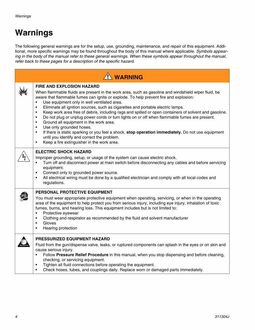
WarningsThe following general warnings are for the setup, use, grounding, maintenance, and repair of this equipment. Addi-tional, more specific warnings may be found throughout the body of this manual where applicable. Symbols appear-ing in the body of the manual refer to these general warnings. When these symbols appear throughout the manual, refer back to these pages for a description of the specific hazard.
WARNINGFIRE AND EXPLOSION HAZARD When flammable fluids are present in the work area, such as gasoline and windshield wiper fluid, be aware that flammable fumes can ignite or explode. To help prevent fire and explosion:• Use equipment only in well ventilated area.• Eliminate all ignition sources, such as cigarettes and portable electric lamps. • Keep work area free of debris, including rags and spilled or open containers of solvent and gasoline.• Do not plug or unplug power cords or turn lights on or off when flammable fumes are present.• Ground all equipment in the work area.• Use only grounded hoses.• If there is static sparking or you feel a shock, stop operation immediately. Do not use equipment
until you identify and correct the problem.• Keep a fire extinguisher in the work area.
ELECTRIC SHOCK HAZARD Improper grounding, setup, or usage of the system can cause electric shock.• Turn off and disconnect power at main switch before disconnecting any cables and before servicing
equipment.• Connect only to grounded power source.• All electrical wiring must be done by a qualified electrician and comply with all local codes and
regulations.
PERSONAL PROTECTIVE EQUIPMENT You must wear appropriate protective equipment when operating, servicing, or when in the operating area of the equipment to help protect you from serious injury, including eye injury, inhalation of toxic fumes, burns, and hearing loss. This equipment includes but is not limited to:• Protective eyewear • Clothing and respirator as recommended by the fluid and solvent manufacturer• Gloves• Hearing protection
PRESSURIZED EQUIPMENT HAZARD Fluid from the gun/dispense valve, leaks, or ruptured components can splash in the eyes or on skin and cause serious injury.• Follow Pressure Relief Procedure in this manual, when you stop dispensing and before cleaning,
checking, or servicing equipment. • Tighten all fluid connections before operating the equipment.• Check hoses, tubes, and couplings daily. Replace worn or damaged parts immediately.

Warnings
311304J 5
EQUIPMENT MISUSE HAZARD Misuse can cause death or serious injury.• Do not operate the unit when fatigued or under the influence of drugs or alcohol.• Do not exceed the maximum working pressure or temperature rating of the lowest rated system
component. See Technical Data in all equipment manuals.• Use fluids and solvents that are compatible with equipment wetted parts. See Technical Data in all
equipment manuals. Read fluid and solvent manufacturer’s warnings. For complete information about your material, request MSDS forms from distributor or retailer.
• Check equipment daily. Repair or replace worn or damaged parts immediately with genuine Graco replacement parts only.
• Do not alter or modify equipment.• Use equipment only for its intended purpose. Call your Graco distributor for information.• Route hoses and cables away from traffic areas, sharp edges, moving parts, and hot surfaces.• Do not kink or over bend hoses or use hoses to pull equipment.• Keep children and animals away from work area.• Comply with all applicable safety regulations.
BURN HAZARD Equipment surfaces and fluid that’s heated can become very hot during operation. To avoid severe burns, do not touch hot fluid or equipment. Wait until equipment/fluid has cooled completely.
WARNING
Installation
6 311304J
Installation
When unpacking pump, check for shipping damage. Report any shipping damage to delivering carrier imme-diately.
Mounting Pump
1. Apply PTFE thread tape (provided with the pump) to large thread of bung adapter (9) (2 in. X 1 ½ in. reducer fitting). Install bung adapter to fuel tank.
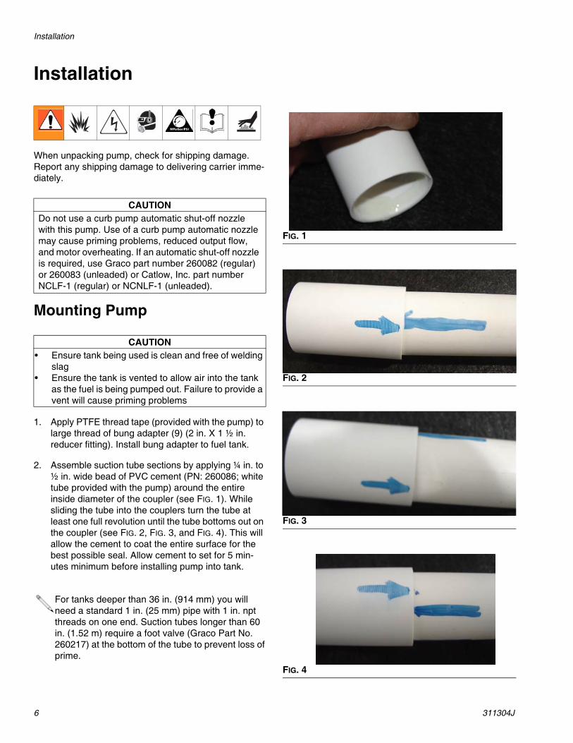
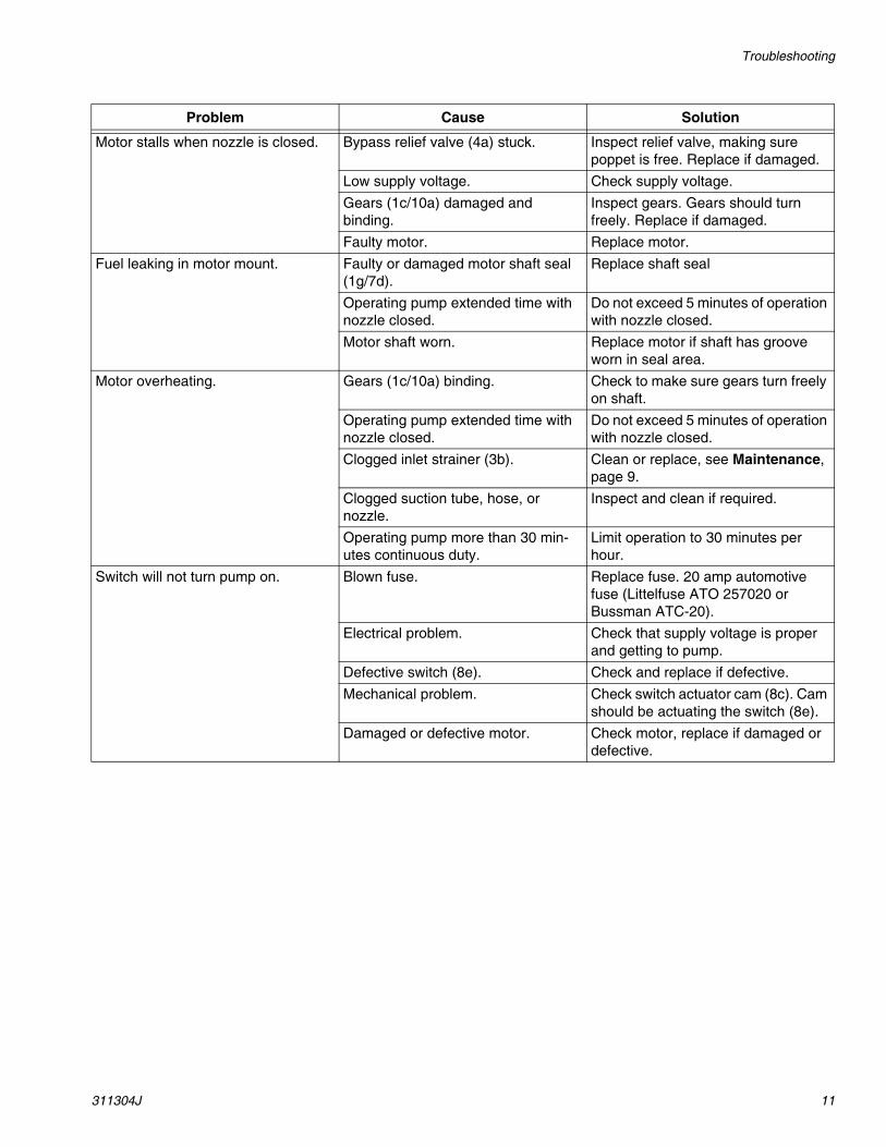
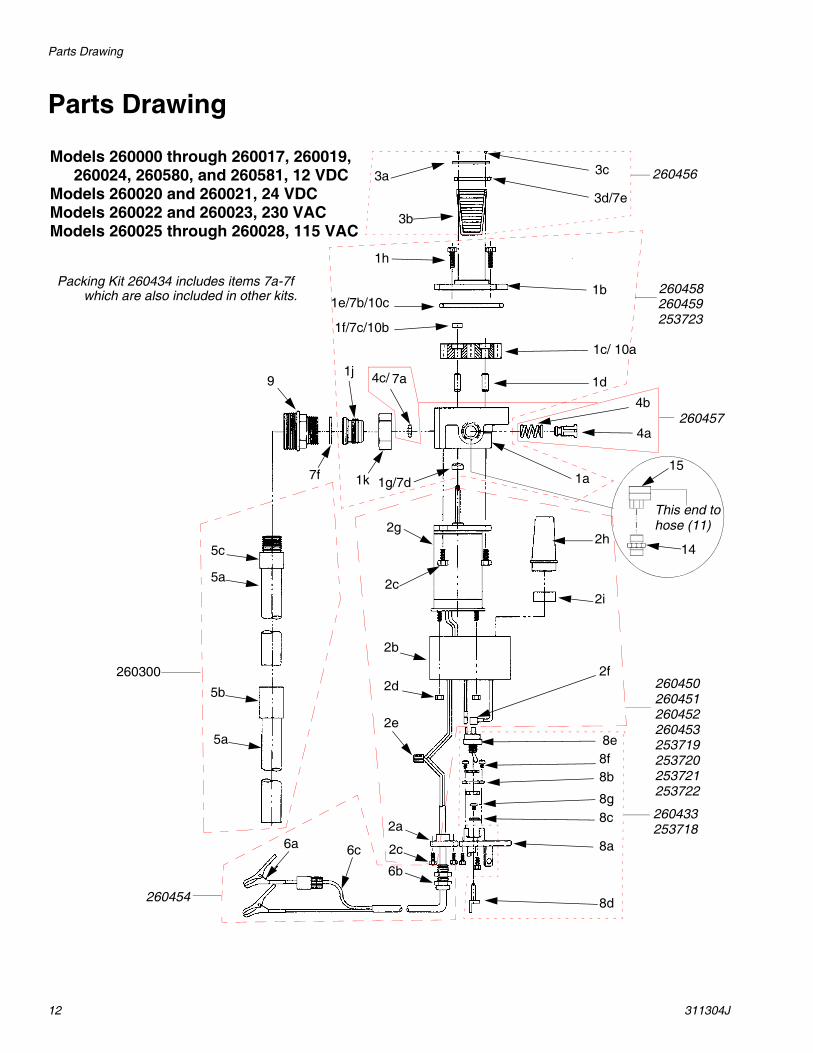
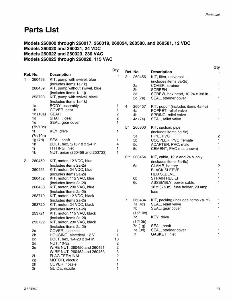
2. Assemble suction tube sections by applying ¼ in. to ½ in. wide bead of PVC cement (PN: 260086; white tube provided with the pump) around the entire inside diameter of the coupler (see FIG. 1). While sliding the tube into the couplers turn the tube at least one full revolution until the tube bottoms out on the coupler (see FIG. 2, FIG. 3, and FIG. 4). This will allow the cement to coat the entire surface for the best possible seal. Allow cement to set for 5 min-utes minimum before installing pump into tank.
CAUTIONDo not use a curb pump automatic shut-off nozzle with this pump. Use of a curb pump automatic nozzle may cause priming problems, reduced output flow, and motor overheating. If an automatic shut-off nozzle is required, use Graco part number 260082 (regular) or 260083 (unleaded) or Catlow, Inc. part number NCLF-1 (regular) or NCNLF-1 (unleaded).
CAUTION• Ensure tank being used is clean and free of welding
slag • Ensure the tank is vented to allow air into the tank
as the fuel is being pumped out. Failure to provide a vent will cause priming problems
For tanks deeper than 36 in. (914 mm) you will need a standard 1 in. (25 mm) pipe with 1 in. npt threads on one end. Suction tubes longer than 60 in. (1.52 m) require a foot valve (Graco Part No. 260217) at the bottom of the tube to prevent loss of prime.
FIG. 1
FIG. 2
FIG. 3
FIG. 4

Installation
311304J 7
3. Cut the suction tube so that it is 2 in. (55 mm) from the bottom of the tank when installed in the tank.
4. Insert gasket (7f) into union nut (1k). If using Graco supplied PVC suction tube it is not necessary to apply thread tape before assembly, just screw into pump inlet (1j). If using metal suction tube (not sup-plied with pump) then apply thread tape provided with pump to NPT threads before assembling to pump inlet (1j).
5. Insert suction tube attached to pump through bung adapter (9) into tank. Position pump as desired and tighten union nut (1k) on bung adapter (9).
Mounting Hose and Nozzle1. Apply thread tape provided with pump to both ends
of hose assembly. Screw ¾” NPT end of 90° union swivel (15) to one end of hose (see fig. 5).
2. Screw nozzle onto other end of hose and tighten.
3. Start swivel end of 90° union swivel (15) onto ¾” nipple (14) on pump outlet (see FIG. 5). Orient the hose/nozzle assembly to desired position and tighten swivel fitting.
It is important that the swivel end of the 90° union swivel (15) is assembled to the ¾” outlet nipple (14) for proper sealing (see FIG. 6). If the pump has diffi-culty priming, it is easy to remove the swivel and pour fluid into the pump outlet cavity when assem-bled this way.
FIG. 5
FIG. 6

Installation
8 311304J
Electrical Installation 12 VDC and 24 VDC
To install wiring for a negative ground system:
1. Ensure pump switch is OFF.
2. To remove electrical cover (2a), remove four bolts (2c).
3. Strip 3 in. (76 mm) of outside insulation from power cable (6c) from end opposite of fuse.
4. Strip 3/8 in. (10 mm) of insulation from red and black wires.
5. Slide strain relief (6b) over end of power cable (6c) on the end just stripped. Male thread of strain relief should be toward stripped end.
6. Insert power cable through conduit thread in electri-cal cover (2a). Connect wires from power cable to wires from the motor using wire nuts (2e): red to red and black to black.
7. Screw strain relief (6b) into electrical cover (2a).
8. Position power cable (6c) so the large diameter of power cable extends through strain relief (6b).
9. Tighten nut on strain relief to form a seal around the power cable.
10. Reinstall electrical cover (2a) on the pump.
11. Remove 1/2 in. (13 mm) of insulation from wires on the fuse holder end of the power cable.
12. Attach battery clamps (6a) with red sleeve to red wire and black sleeve to black wire. Wire must be crimped to the battery clamp firmly to get a good electrical connection.
13. Connect red wire with fuse holder inline to positive battery terminal. Connect black wire to negative bat-tery terminal.
Electrical Installation115 VAC and 230 VAC
1. Ensure pump switch is OFF and electrical power is disconnected.
2. Install conduit and user-supplied power cord to pump.
3. Strip 3 in. (76 mm) from power cord jacket and 1/2 in. (13 mm) from individual conductor insulation.
4. To remove electrical cover (2a), remove four bolts (2c).
5. Remove 1/2 in. (13 mm) of insulation from power wires inside pump electrical terminal cavity.
6. Insert electrical power wire through conduit opening in back of pump.
7. Using wire nuts (2e), connect wires: green to green, white to white, and black to black.
8. Replace electrical cover.
If you are installing models 260580 or 260581 skip this section. These pumps have been factory wired
Power cable can be cut to shorter length if 18 feet (5.5 m) is not required. Cut to proper length and proceed with steps 3 and 4.
On 115 VAC and 230 VAC pumps, electrical con-nections must be made by a licensed electrician per requirements of local, state, and national codes regarding class 1, group D installations. Only rigid conduit with threaded connections or other approved wiring methods for Class 1 or Division 1 installations should be used. Conduit opening in pump must be sealed with waterproof, fuel-resistant sealant. Failure to comply with this warning could result in injury from electrical shock, fire or explo-sion.

Operation
311304J 9
Priming PumpAll pump models should prime within 5 seconds after pump is turned on up to a height of 36 in. (91 mm). Pumps installed at height up to 5 ft. (1.52 m) may have difficulty priming. Follow procedure below to initiate prime. Pumps installed at suction height above 5 ft. (1.52 m) will have difficulty in holding prime. It is recom-mended that check valve (Graco part no. 260217) be added to the bottom of the suction tube to help maintain prime.
If prime in not achieved in 30 seconds after turning the pump on use the following procedure to initiate prime;
1. Remove 90° Union Swivel (15) from ¾” Inlet Nipple (14).
2. Pour fluid being pumped into pump outlet until com-pletely filled.
3. Re-assemble Union Swivel (15) back onto nipple (14). Turn pump on. The pump should gain prime in under 5 seconds.
4. If pump still does not gain prime check for any major leaks in the system. If no leaks are found then the pump is mechanically defective and should be reported to Graco Product Service for disposition.
It is important that the swivel end of the 90° union swivel (15) is assembled to the ¾” outlet nipple (14) for proper sealing (see fig. 6). Also, if the pump has difficulty priming it is easy to remove the swivel and pour fluid into the pump outlet cavity when assem-bled this way.
If prime is lost1. First make sure there are no fluid leaks from the
pump outlet out to the fuel nozzle. Any leaks after the outlet will allow air to push the fluid column back to the tank and prime will be lost.
2. If no leaks are detected on the outlet side of the pump, remove the pump from the tank and inspect the suction tube and pump inlet for leaks.
3. If the system is leak free and the suction height guidelines are followed the pumping system should not lose prime.
Operation
On/Off switch lever (8d) is located under nozzle holder. Remove nozzle before turning pump on.
1. Move switch lever (8d) on.
2. Insert nozzle into tank and actuate nozzle lever to dispense fuel.
3. Immediately after fueling turn switch lever (8d) off.
Maintenance1. Clean inlet strainer (3b) after every 50 hours of
operation.
2. To remove inlet strainer (3b), remove four screws (3c) and strainer cover (3a). Remove and clean strainer.
3. If strainer is excessively dirty, clean tank to protect pump and the equipment being fueled.
4. After cleaning strainer, replace strainer and cover. Make sure cover seal (3d/7e) is in place.
All guidelines and procedures are based on pump-ing diesel fuel. If pumping gasoline priming may be more difficult due to the lift of gasoline dependent on Reid's vapor pressure of the gasoline and it's temperature. The lower the vapor pressure and temperature, the higher the possible lift.
Before servicing, turn pump off and open the nozzle to relieve pressure.
CAUTIONDo not operate pump dry. Do not run pump for more than 5 minutes with nozzle closed. Do not operate pump for more than 30 minutes continuously in 1 hour.

Troubleshooting
10 311304J
Troubleshooting
Problem Cause Solution
Motor runs but pump will not prime. Motor rotation wrong. (12 VDC and 24 VDC units only.)
Check wiring instructions for possible problems.
Missing relief valve o-ring seal (4c/7a).
Remove gear cover (1b) inspect seal (4c/7a), replace if missing or damaged.
Sheared drive key (1f/7c). Remove cover (1b) and inspect key (1f/7c/10b), replace if worn or sheared.
Dirt under relief poppet (4a) or seal (4c/7a).
Remove cover (1b) and inspect, clean or replace if damaged.
Strainer seal (3d/7e) leaking. Inspect and replace if damaged.Suction height too high to prime. See Priming Pump, page 9.Worn or damaged gears. Remove cover (1b) and inspect
gears. Replace if worn or damaged.Fuel level low. Refill tank.Cover seal (1e7b/10c) damaged. Replace if worn or damaged.Inlet strainer (3b) clogged. Remove and clean or replace.Air leak in suction tube. Inspect all joints in suction tube.
Make sure all joints in suction tube are sealed. and that there are no cracks from over-tightening
Air lock in system. This may occur if filter or meter or automatic shut-off nozzle is used. If this occurs, fill pump and meter with fuel through top of pump.
Motor does not run at proper speed. Check electric connections. Check supply voltage for proper voltage level.
Unit pumps but output flow is low. Clogged inlet strainer (3b). Clean or replace.Air leak in suction tube. Check to make sure all joints in suc-
tion tube are sealed and that there are no cracks.
Suction tube too close to tank bottom.
Suction tube must have a 2 in. (51 mm) minimum clearance.
Tank empty. Refill tank.Tank not vented. Tank must be vented to atmosphere.Worn or damaged gears. Remove cover (1b) and inspect
gears. Replace if worn or damaged.Damaged motor. Replace motor.Clogged suction tube, hose, or nozzle.
Inspect and clean.
Troubleshooting
311304J 11
Motor stalls when nozzle is closed. Bypass relief valve (4a) stuck. Inspect relief valve, making sure poppet is free. Replace if damaged.
Low supply voltage. Check supply voltage.Gears (1c/10a) damaged and binding.
Inspect gears. Gears should turn freely. Replace if damaged.
Faulty motor. Replace motor.Fuel leaking in motor mount. Faulty or damaged motor shaft seal
(1g/7d).Replace shaft seal
Operating pump extended time with nozzle closed.
Do not exceed 5 minutes of operation with nozzle closed.
Motor shaft worn. Replace motor if shaft has groove worn in seal area.
Motor overheating. Gears (1c/10a) binding. Check to make sure gears turn freely on shaft.
Operating pump extended time with nozzle closed.
Do not exceed 5 minutes of operation with nozzle closed.
Clogged inlet strainer (3b). Clean or replace, see Maintenance, page 9.
Clogged suction tube, hose, or nozzle.
Inspect and clean if required.
Operating pump more than 30 min-utes continuous duty.
Limit operation to 30 minutes per hour.
Switch will not turn pump on. Blown fuse. Replace fuse. 20 amp automotive fuse (Littelfuse ATO 257020 or Bussman ATC-20).
Electrical problem. Check that supply voltage is proper and getting to pump.
Defective switch (8e). Check and replace if defective.Mechanical problem. Check switch actuator cam (8c). Cam
should be actuating the switch (8e).Damaged or defective motor. Check motor, replace if damaged or
defective.
Problem Cause Solution
Parts Drawing
12 311304J
Parts Drawing
3a 3c
3d/7e
1a
8e
8b8f
8g
1h
1e/7b/10c
1f/7c/10b
2e
2f
3b
1b
1c/ 10a
1d
4b
4a
2h
2i
8c
8a
8d
4c/9
7f 1k 1g/7d
2g
2c
2b
2d
5c
5a
2a
2c
6b
6c6a
Models 260000 through 260017, 260019,260024, 260580, and 260581, 12 VDC
Models 260020 and 260021, 24 VDCModels 260022 and 260023, 230 VACModels 260025 through 260028, 115 VAC
1j
260450260451260452260453
260457
260454
260456
260459260458
260433
7a
Packing Kit 260434 includes items 7a-7f which are also included in other kits.
260300
5a
5b
253723
253719253720253721253722
253718
15
14
This end tohose (11)
Parts List
311304J 13
Parts ListModels 260000 through 260017, 260019, 260024, 260580, and 260581, 12 VDCModels 260020 and 260021, 24 VDCModels 260022 and 260023, 230 VACModels 260025 through 260028, 115 VAC
Ref. No. DescriptionQty
.1 260458 KIT, pump with swivel, blue
(includes items 1a-1k)260459 KIT, pump without swivel, blue
(includes items 1a-1j)253723 KIT, pump with swivel, black
(includes items 1a-1k)1a BODY, assembly 11b COVER, gear 11c (10a) GEAR 21d SHAFT, gear 21e (7b/10c)
SEAL, gear cover 1
1f (7c/10b)
KEY, drive 1
1g (7d) SEAL, shaft 11h BOLT, hex, 5/16-18 x 3/4 in. 41j FITTING, inlet 11k NUT, union (260458 and 253723) 1
2 260450 KIT, motor, 12 VDC, blue(includes items 2a-2i)
260451 KIT, motor, 24 VDC, blue(includes items 2a-2i)
260452 KIT, motor, 115 VAC, blue(includes items 2a-2i)
260453 KIT, motor, 230 VAC, blue(includes items 2a-2i)
253719 KIT, motor, 12 VDC, black(includes items 2a-2i)
253720 KIT, motor, 24 VDC, black(includes items 2a-2i)
253721 KIT, motor, 115 VAC, black(includes items 2a-2i)
253722 KIT, motor, 230 VAC, black(includes items 2a-2i)
2a COVER, electrical 12b HOUSING, electrical, 12 V 12c BOLT, hex, 1/4-20 x 3/4 in. 102d NUT, 10-32 22e WIRE NUT, 260450 and 260451 2
WIRE NUT, 260452 and 260453 32f FLAG TERMINAL 22g MOTOR, electric 12h COVER, nozzle 12i GUIDE, nozzle 1
3 260456 KIT, filter, universal (includes items 3a-3d)
3a COVER, strainer 13b SCREEN 13c SCREW, hex head, 10-24 x 3/8 in.3d (7e) SEAL, strainer cover 1
4 260457 KIT, popoff (includes items 4a-4c)4a POPPET, relief valve 14b SPRING, relief valve 14c (7a) SEAL, relief valve 1
5* 260300 KIT, suction, pipe(includes items 5a-5c)
5a PIPE, PVC 25b COUPLER, PVC, female 15c ADAPTER, PVC, male 15d CEMENT, PVC (not shown) 1
6** 260454 KIT, cable, 12 V and 24 V only (includes items 6a-6c)
6a CLAMP, battery 2BLACK SLEEVE 1RED SLEEVE 1
6b STRAIN RELIEF 16c ASSEMBLY, power cable,
18 ft (5.5 m), fuse holder, 20 amp fuse
1
7 260434 KIT, packing (includes items 7a-7f) 17a (4c) SEAL, relief valve 17b (1e/10c)
SEAL, gear cover 1
7c (1f/10b)
KEY, drive 1
7d (1g) SEAL, shaft 17e (3d) SEAL, strainer cover 17f GASKET, inlet 1
Ref. No. DescriptionQty
.

Parts List (continued)
14 311304J
Parts List (continued)Models 260000 through 260017, 260019, and 260024, 12 VDCModels 260020 and 260021, 24 VDCModels 260022 and 260023, 230 VACModels 260025 through 260028, 115 VAC
Replacement Danger and Warning labels, tags, and cards are available at no cost.
* Not used on models 260004, 260006, 260008, 260009, 260010, 260013, 260014, 260015, 260017, 260019, 260024, 260580, and 260581
** Used on 12 VDC and 24 VDC models only
Ref. No. DescriptionQty
.8 260433 KIT, switch, blue
(includes items 8a-8g)253718 KIT, switch, black
(includes items 8a-8g)8a COVER, switch 18b BRACKET, switch 18c CAM, actuator switch 18d SWITCH, actuator assy. 18e SWITCH 18f SCREW, phillips, 8-32 x 3/8 in. 28g SCREW, phillips, 6-32 x 1/4 in. 1
9 260061 ADAPTER, bung 1
10 260277 KIT, gear (includes 10a-10c) 110a (1c) GEAR 210b (1f/7c)
KEY, drive 1
10c (1e/7b)
SEAL, gear, cover 1
11 see pg. 2 ASSEMBLY, hose, 3/4 in. (not shown)
12 see pg. 2 ASSEMBLY, nozzle, (not shown)
1315G901 LABEL, warning (not shown)14 15F074 NIPPLE, 3/4 in. x 3/4 in. 115 156589 ADAPTER, 90° swivel 1

Technical Data
311304J 15
Technical Data
Valox® is a registered trademark of the General Electric Company
Performance Chart
Working pressure 10 psi (0.07 MPa, 0.7 bar)Inlet size 1 in. nptOutlet size 3/4 in. nptWeight 20 lb (9 kg)Power cable 18 ft (5.5 m), 14 AWG (12 VDC and 24 VDC models only)Current draw 12 VDC models: 12.5 amps
24 VDC models: 7 amps115 VAC models: 2 amps230 VAC models: 1 amps
Duty cycle 30 min/hourSuction tube 1 in. x 34 in. (25.4 mm x 864 mm)Wetted parts carbon steel with zinc plating, 416 and 302 stainless
steel, fluoroelastomer, Buna-N, Aluminum, Valox®, Nylon, Nitrile, PVC, Vellumoid,

All written and visual data contained in this document reflects the latest product information available at the time of publication. Graco reserves the right to make changes at any time without notice.
This manual contains English. MM 311304
Graco Headquarters: MinneapolisInternational Offices: Belgium, China, Japan, Korea
GRACO INC. P.O. BOX 1441 MINNEAPOLIS, MN 55440-1441Copyright 2005, Graco Inc. is registered to ISO 9001
www.graco.comRevised March 2015
Graco Standard WarrantyGraco warrants all equipment referenced in this document which is manufactured by Graco and bearing its name to be free from defects in material and workmanship on the date of sale to the original purchaser for use. With the exception of any special, extended, or limited warranty published by Graco, Graco will, for a period of twelve months from the date of sale, repair or replace any part of the equipment determined by Graco to be defective. This warranty applies only when the equipment is installed, operated and maintained in accordance with Graco’s written recommendations.
This warranty does not cover, and Graco shall not be liable for general wear and tear, or any malfunction, damage or wear caused by faulty installation, misapplication, abrasion, corrosion, inadequate or improper maintenance, negligence, accident, tampering, or substitution of non-Graco component parts. Nor shall Graco be liable for malfunction, damage or wear caused by the incompatibility of Graco equipment with structures, accessories, equipment or materials not supplied by Graco, or the improper design, manufacture, installation, operation or maintenance of structures, accessories, equipment or materials not supplied by Graco.
This warranty is conditioned upon the prepaid return of the equipment claimed to be defective to an authorized Graco distributor for verification of the claimed defect. If the claimed defect is verified, Graco will repair or replace free of charge any defective parts. The equipment will be returned to the original purchaser transportation prepaid. If inspection of the equipment does not disclose any defect in material or workmanship, repairs will be made at a reasonable charge, which charges may include the costs of parts, labor, and transportation.
THIS WARRANTY IS EXCLUSIVE, AND IS IN LIEU OF ANY OTHER WARRANTIES, EXPRESS OR IMPLIED, INCLUDING BUT NOT LIMITED TO WARRANTY OF MERCHANTABILITY OR WARRANTY OF FITNESS FOR A PARTICULAR PURPOSE.
Graco’s sole obligation and buyer’s sole remedy for any breach of warranty shall be as set forth above. The buyer agrees that no other remedy (including, but not limited to, incidental or consequential damages for lost profits, lost sales, injury to person or property, or any other incidental or consequential loss) shall be available. Any action for breach of warranty must be brought within two (2) years of the date of sale.
GRACO MAKES NO WARRANTY, AND DISCLAIMS ALL IMPLIED WARRANTIES OF MERCHANTABILITY AND FITNESS FOR A PARTICULAR PURPOSE, IN CONNECTION WITH ACCESSORIES, EQUIPMENT, MATERIALS OR COMPONENTS SOLD BUT NOT MANUFACTURED BY GRACO. These items sold, but not manufactured by Graco (such as electric motors, switches, hose, etc.), are subject to the warranty, if any, of their manufacturer. Graco will provide purchaser with reasonable assistance in making any claim for breach of these warranties.
In no event will Graco be liable for indirect, incidental, special or consequential damages resulting from Graco supplying equipment hereunder, or the furnishing, performance, or use of any products or other goods sold hereto, whether due to a breach of contract, breach of warranty, the negligence of Graco, or otherwise.
FOR GRACO CANADA CUSTOMERSThe Parties acknowledge that they have required that the present document, as well as all documents, notices and legal proceedings entered into, given or instituted pursuant hereto or relating directly or indirectly hereto, be drawn up in English. Les parties reconnaissent avoir convenu que la rédaction du présente document sera en Anglais, ainsi que tous documents, avis et procédures judiciaires exécutés, donnés ou intentés, à la suite de ou en rapport, directement ou indirectement, avec les procédures concernées.
Graco Information For the latest information about Graco products, visit www.graco.com.
For patent information, see www.graco.com/patents.
TO PLACE AN ORDER, contact your Graco distributor or call to identify the nearest distributor.Phone: 612-623-6928 or Toll Free: 1-800-533-9655, Fax: 612-378-3590