Embed Size (px)
Citation preview

[Type the document title]
Polycom Document Title 1
3.1.0 | October 2013 | 3725-26945-007/C
Polycom® Immersive Telepresence(ITP) Administrator’s Guide

© 2013 Polycom, Inc. All rights reserved.
Polycom, Inc. 6001 America Center Drive San Jose CA 95002 USA
No part of this document may be reproduced or transmitted in any form or by any means, electronic or mechanical, for any purpose, without the express written permission of Polycom, Inc. Under the law, reproducing includes translating into another language or format.
As between the parties, Polycom, Inc., retains title to and ownership of all proprietary rights with respect to the software contained within its products. The software is protected by United States copyright laws and international treaty provision. Therefore, you must treat the software like any other copyrighted material (e.g., a book or sound recording).
Every effort has been made to ensure that the information in this manual is accurate. Polycom, Inc., is not responsible for printing or clerical errors. Information in this document is subject to change without notice.
ii
Trademark Information
POLYCOM® and the names and marks associated with Polycom's products are trademarks and/or service marks of Polycom, Inc., and are registered and/or common law marks in the United States and various other countries.
All other trademarks are the property of their respective owners.
Patent Information
The accompanying product may be protected by one or more U.S. and foreign patents and/or pending patent applications held by Polycom, Inc.
Polycom, Inc. iii
About this GuideThe Polycom Immersive Telepresence (ITP) Administrator’s Guide is intended for IT administrators, Polycom-authorized technicians, and Video Network Operations Center (VNOC) conference producers who need to:
• Upgrade the HDX® software and configure the System Controller
• Load the Polycom Touch Control or Crestron Touch Panel software
• Configure the System_Config.ini file
• Install and use the Polycom Telepresence Tool
• Pair the Polycom Touch Control with the HDX codec and the System Controller
• Configure the H.323 gatekeeper, SIP server, and global directory
• Manage Favorites and the local directory
• Enable TIP, user-initiated multipoint conferences, and DBA
• Maintain the ITP rooms
The information in this guide can also be used by VNOC technical support and Polycom-certified product installers of Polycom ITP solutions.
This guide covers the following ITP solutions: Polycom RealPresence® Experience (RPX™) 400 Series and RPX 200 Series, Polycom Open Telepresence Experience™ (OTX™) 300 and OTX 100, Polycom Telepresence Experience® (TPX®) 306M and TPX 204M, and Polycom Architected Telepresence Experience™ (ATX™).
If you are using the ATX Software Developer’s Kit (SDK), some of the functionality described in this guide may not be available depending on which capabilities your integrator chose to include.

Polycom Immersive Telepresence (ITP) Administrator’s Guide
iv Polycom, Inc.
PrerequisitesTo perform the tasks in this guide, you should have prior knowledge and experience with:
• Polycom Immersive Telepresence solutions
• Polycom HDX systems
In addition, depending on your configuration, you may also need to be familiar with:
• Polycom RMX® hardware models 2000 and higher with the Telepresence option enabled (refer to the Polycom Immersive Telepresence Deployment Guide for specific hardware model and software version compatibility)
• Polycom Multipoint Layout Application (needed for use with the RMX conference platform)
• Polycom Converged Management Application™ (CMA®)
Related DocumentationFor additional information, refer to these related Polycom documents:
• ITP documentation: Polycom Immersive Telepresence Deployment Guide, Polycom ITP User’s Guide, Polycom ITP Quick Reference, Polycom ATX 300 Integrator’s Guide, Polycom Multipoint Layout Application (MLA) User Guide, Polycom Telepresence Solutions Network Requirements
• HDX documentation: Administrator’s Guide for Polycom HDX Systems, Installing Polycom HDX Software and Options
• RMX documentation: Polycom RMX 1500/2000/4000 Administrator’s Guide
• CMA documentation: Polycom CMA System Operations Guide, System Administrator Guide for the Polycom Conferencing Add-in for Microsoft® Outlook®, Polycom Unified Communications Deployment Guide for Microsoft Environments, Polycom Unified Communications for Cisco® Environments
• Release Notes: Polycom RPX HD 400 and 200 Series Release Notes, Polycom OTX Systems Release Notes, Polycom TPX HD Release Notes, Polycom ATX Release Notes, Polycom MLA Release Notes, Polycom HDX Systems Release Notes, Polycom RMX 1500/2000/4000 Release Notes, Polycom CMA System Release Notes
Many of the documents listed on this page, as well as additional Polycom documents, are available at http://www.polycom.com/support/video/index.html.
Support
Polycom, Inc. v
SupportFor telepresence support or service, please call one of these numbers:
• North America: 888-248-4143
• EMEA: +44 1753 723020
• APAC (Asia Pacific): +612 997 88098
Alternatively, you can access the Polycom Support Portal at http://support.polycom.com.

Polycom Immersive Telepresence (ITP) Administrator’s Guide
vi Polycom, Inc.

Polycom, Inc. vii
Contents
1 Configuring the HDX Codecs and the System Controller 1Configuring the HDX Codecs . . . . . . . . . . . . . . . . . . . . . . . . . . . . . . . . . . 1
Upgrading the Polycom HDX Software . . . . . . . . . . . . . . . . . . . . . . . . 1
Setting the Date and Time . . . . . . . . . . . . . . . . . . . . . . . . . . . . . . . . . 3
Enabling HDX ITP System Communication . . . . . . . . . . . . . . . . . . . . 4
Configuring the System Controller . . . . . . . . . . . . . . . . . . . . . . . . . . . . . . 5
Configuring the LAN . . . . . . . . . . . . . . . . . . . . . . . . . . . . . . . . . . . . . . 6
Connecting to the System Controller . . . . . . . . . . . . . . . . . . . . . . . . . 7
Upgrading the System Controller Firmware . . . . . . . . . . . . . . . . . . . 11Confirming the System Controller Firmware Version . . . . . . . . . 11Downloading the System Controller Firmware . . . . . . . . . . . . . . 12
Loading the System Controller Software . . . . . . . . . . . . . . . . . . . . . 12
2 Loading the Polycom Touch Control or Crestron Touch Panel Software . . . . . . . . . . . . . . . . . . . . . . . . . . . . . . . . . . 15
Loading the Polycom Touch Control Operating System and Software . . 15
Loading the Crestron Touch Panel Software and Firmware . . . . . . . . . . 16
Loading the Touch Panel Software . . . . . . . . . . . . . . . . . . . . . . . . . . 16
Upgrading the Touch Panel Firmware . . . . . . . . . . . . . . . . . . . . . . . 18Confirming the Touch Panel Firmware Version . . . . . . . . . . . . . 18Downloading the Touch Panel Firmware . . . . . . . . . . . . . . . . . . 19
3 Configuring System Parameters with the System_Config.ini File . . . . . . . . . . . . . . . . . . . . . . . . . . . 21
Editing the System_Config.ini File . . . . . . . . . . . . . . . . . . . . . . . . . . . . . 21
Downloading the System_Config.ini File onto the System Controller . . . 25
Enabling Optional Features . . . . . . . . . . . . . . . . . . . . . . . . . . . . . . . . . . . 26
Selecting the Enhanced or the Classic User Interface . . . . . . . . . . . 26
Selecting the Video Format Preference . . . . . . . . . . . . . . . . . . . . . . 29
Enabling the Document Camera . . . . . . . . . . . . . . . . . . . . . . . . . . . . 30
Selecting the Document Camera or the PC as the Content Source . 31
Adding a Label to the Auxiliary Content Button . . . . . . . . . . . . . . . . 32

Polycom Immersive Telepresence (ITP) Administrator’s Guide
viii Polycom, Inc.
Viewing Content on the Displays When Not in a Call . . . . . . . . . . . . 32
Enabling or Disabling the Lifts for the Tabletop Content Monitors . . 33
Automatically Lifting the Tabletop Content Monitors . . . . . . . . . . . . 34
Disabling Dimming on TPX LG Displays . . . . . . . . . . . . . . . . . . . . . 34
Enabling Close Up or Wide Shot Camera Views . . . . . . . . . . . . . . . 35
4 Installing and Using the Polycom Telepresence Tool . . 37Installing the Telepresence Tool . . . . . . . . . . . . . . . . . . . . . . . . . . . . . . . 37
Connecting to the Codecs with the Telepresence Tool . . . . . . . . . . . . . . 38
Configuring the Codecs with the Telepresence Tool . . . . . . . . . . . . . . . 44
Performing Other Tasks with the Telepresence Tool . . . . . . . . . . . . . . . 47
Updating Passwords on the HDX Codecs . . . . . . . . . . . . . . . . . . . . 51
Using the Telepresence Tool Address Book . . . . . . . . . . . . . . . . . . 52
Using the HDX Directory Downgrade Tool . . . . . . . . . . . . . . . . . . . . 53
5 Pairing the Polycom Touch Control with the HDX Codec and the System Controller . . . . . . . . . . . . . . . . . . 55
Pairing the Polycom Touch Control with the Primary HDX Codec . . . . . 55
Pairing the Polycom Touch Control with the System Controller . . . . . . . 58
Unpairing the Polycom Touch Control . . . . . . . . . . . . . . . . . . . . . . . . . . 60
6 Configuring the H.323 Gatekeeper, SIP Server, and Global Directory . . . . . . . . . . . . . . . . . . . . . . . . . . . . . . . . 61
Configuring ITP Systems for Use with an H.323 Gatekeeper . . . . . . . . . 61
Configuring ITP Systems for SIP . . . . . . . . . . . . . . . . . . . . . . . . . . . . . . 63
Enabling the Telepresence Interoperability Protocol (TIP) . . . . . . . . . . . 64
Configuring ITP Systems for Use with the CMA System Directory . . . . . 66
Configuring the ITP Rooms to Access the CMA System Directory Server . . . . . . . . . . . . . . . . . . . . . . . . . . . . . . . . . . . . . . . . . . . . . . . . 66
Creating ITP Rooms and Associating Endpoints Using the CMA System . . . . . . . . . . . . . . . . . . . . . . . . . . . . . . . . . . . . . . . . . . . . . . . 68
Creating Groups and Associating Members Using the CMA System 69
Configuring ITP Systems for Use with a Lync Server . . . . . . . . . . . . . . . 70
Enabling HD Video on the Lync Server . . . . . . . . . . . . . . . . . . . . . . 70
Creating and Enabling Conference Room User Accounts . . . . . . . . 70
Hiding the Secondary Codecs in the Lync Directory . . . . . . . . . . . . 71
Configuring ITP Systems for the Microsoft Environment . . . . . . . . . 71
Contents
Polycom, Inc. ix
7 Managing Favorites and the Local Directory . . . . . . . . . 73Managing Favorites with a Polycom Touch Control . . . . . . . . . . . . . . . . 73
Importing the Speed Dials from the System_Config.ini File . . . . . . . 74
Configuring Favorites . . . . . . . . . . . . . . . . . . . . . . . . . . . . . . . . . . . . 75Configuring the Help Desk Number . . . . . . . . . . . . . . . . . . . . . . 77Configuring Single Site Entries . . . . . . . . . . . . . . . . . . . . . . . . . . 78Configuring Groups . . . . . . . . . . . . . . . . . . . . . . . . . . . . . . . . . . 81
Managing the Local Directory with a Crestron Touch Panel . . . . . . . . . . 82
Importing the Speed Dials from the System_Config.ini File . . . . . . . 83
Configuring the Local Directory Entries . . . . . . . . . . . . . . . . . . . . . . 85Configuring the Help Desk Number . . . . . . . . . . . . . . . . . . . . . . 85Configuring Single Site Entries . . . . . . . . . . . . . . . . . . . . . . . . . . 86Configuring Groups . . . . . . . . . . . . . . . . . . . . . . . . . . . . . . . . . . 89
Configuring Speed Dial Buttons . . . . . . . . . . . . . . . . . . . . . . . . . . . . 90Adding Speed Dial Buttons . . . . . . . . . . . . . . . . . . . . . . . . . . . . 91Changing the Order of Speed Dial Buttons . . . . . . . . . . . . . . . . 92
8 Managing TIP, User-Initiated Multipoint Conferences, and DBA . . . . . . . . . . . . . . . . . . . . . . . . . . . . . . . . . . . . . . . 93
Enabling User-Initiated Multipoint Conferences . . . . . . . . . . . . . . . . . . . 93
Configuring the Polycom MLA, HDX System, and RMX for User-Initiated Multipoint Conferences . . . . . . . . . . . . . . . . . . . . . . . . 94
Configuring the MLA for Automatic Layout Mode . . . . . . . . . . . . 94Setting Up Naming on the HDX Codecs . . . . . . . . . . . . . . . . . . 96Configuring the Polycom RMX Conference Profile . . . . . . . . . . 98
Enabling Polycom Conferencing for Microsoft Outlook . . . . . . . . . . 98
Enabling Meeting Composer and Group Dialing or Multipoint Speed Dialing . . . . . . . . . . . . . . . . . . . . . . . . . . . . . . . . . . . . . . . . . 100
Configuring the ITP Room to Access the Polycom RMX . . . . . 100
Enabling Single Touch Multipoint . . . . . . . . . . . . . . . . . . . . . . . . . . 102Creating a Virtual Meeting Room on the Polycom RMX . . . . . 102Adding a Virtual Meeting Room to Favorites (Sites with a Polycom Touch Control) . . . . . . . . . . . . . . . . . . . . . . . . . . . . . . 103Adding a Virtual Meeting Room to the Local Directory (Sites with a Crestron Touch Panel) . . . . . . . . . . . . . . . . . . . . . . . . . . 103Configuring the Favorites or the Speed Dials for Virtual Meeting Rooms (Sites with a Crestron Touch Panel) . . . . . . . 104TPX Limitation (Sites with a Crestron Touch Panel) . . . . . . . . 104
Disabling Dynamic Bandwidth Allocation (DBA) . . . . . . . . . . . . . . . . . . 104

Polycom Immersive Telepresence (ITP) Administrator’s Guide
x Polycom, Inc.
9 Maintaining the ITP Room . . . . . . . . . . . . . . . . . . . . . . . 105Powering Up and Down . . . . . . . . . . . . . . . . . . . . . . . . . . . . . . . . . . . . 105
Powering Up and Down While Onsite . . . . . . . . . . . . . . . . . . . . . . . 105
Powering Up and Down Remotely (RPX and OTX Sites) . . . . . . . . 106
Configuring the NTSC and PAL Camera Settings (RPX and OTX Sites) . . . . . . . . . . . . . . . . . . . . . . . . . . . . . . . . . . . . . . . . . . . . . . . . . . . 107
Accessing the Security Camera (RPX Sites) . . . . . . . . . . . . . . . . . . . . 107
Accessing the HDX, RMX, and Polycom Touch Control Logs . . . . . . . 109
Accessing the HDX Logs . . . . . . . . . . . . . . . . . . . . . . . . . . . . . . . . 109
Accessing the RMX Logs . . . . . . . . . . . . . . . . . . . . . . . . . . . . . . . . 109
Accessing the Polycom Touch Control Logs . . . . . . . . . . . . . . . . . 110
Checking the Display Settings (OTX and TPX Sites) . . . . . . . . . . . . . . 110
OTX Display Settings . . . . . . . . . . . . . . . . . . . . . . . . . . . . . . . . . . . 111
TPX Display Settings . . . . . . . . . . . . . . . . . . . . . . . . . . . . . . . . . . . 112
Accessing and Using the Admin Screen . . . . . . . . . . . . . . . . . . . . . . . . 121
Accessing the Polycom Touch Control Admin Screen . . . . . . . . . . 121
Accessing the Touch Panel Admin Screen . . . . . . . . . . . . . . . . . . . 123
Using the Admin Screen . . . . . . . . . . . . . . . . . . . . . . . . . . . . . . . . . 124
Using Telnet Commands to Access the System Controller . . . . . . . . . 126
Replacing the Lamps and Bulbs (RPX and OTX Sites) . . . . . . . . . . . . 127
RPX Projector Lamps . . . . . . . . . . . . . . . . . . . . . . . . . . . . . . . . . . . 127
RPX Ceiling Cloud Light Bulbs . . . . . . . . . . . . . . . . . . . . . . . . . . . . 128
OTX Light Bulbs . . . . . . . . . . . . . . . . . . . . . . . . . . . . . . . . . . . . . . . 129
Caring for the Room . . . . . . . . . . . . . . . . . . . . . . . . . . . . . . . . . . . . . . . 129

Polycom, Inc. xi
Figures
Figure 1-1 HDX Web UI Polycom Touch Control Screen . . . . . . . . . . . . . . . . . . . 5
Figure 1-2 Ethernet Field on the Toolbox System Info Screen . . . . . . . . . . . . . . . 6
Figure 1-3 Toolbox Ethernet Addressing Dialog Box . . . . . . . . . . . . . . . . . . . . . . 7
Figure 1-4 Toolbox Address Book Screen (with RS232Connection Type) . . . . . . . . . . . . . . . . . . . . . . . . . . . . . . . . . . . . . . . . 8
Figure 1-5 Toolbox Address Book Screen (with Indirect Connection Type) . . . . . 9
Figure 1-6 Address Book Drop-Down on the Toolbox System Info Screen . . . . . . . . . . . . . . . . . . . . . . . . . . . . . . . . . . . . . 10
Figure 1-7 System Controller Firmware Version on the Toolbox System Info Screen . . . . . . . . . . . . . . . . . . . . . . . . . . . . . . . 11
Figure 1-8 Toolbox Firmware Dialog Box . . . . . . . . . . . . . . . . . . . . . . . . . . . . . . 12
Figure 1-9 Toolbox SIMPL Program Dialog Box . . . . . . . . . . . . . . . . . . . . . . . . 13
Figure 1-10 Toolbox Device Firmware Confirmation Dialog Box . . . . . . . . . . . . . 13
Figure 2-1 Toolbox Project Dialog Box . . . . . . . . . . . . . . . . . . . . . . . . . . . . . . . . 17
Figure 2-2 Toolbox Device Type Confirmation Dialog Box . . . . . . . . . . . . . . . . . 17
Figure 2-3 Version Field on Toolbox System Info Screen . . . . . . . . . . . . . . . . . 18
Figure 2-4 Firmware Dialog Box . . . . . . . . . . . . . . . . . . . . . . . . . . . . . . . . . . . . 19
Figure 3-1 Toolbox File Manager Screen . . . . . . . . . . . . . . . . . . . . . . . . . . . . . . 22
Figure 4-1 Telepresence Tool Select Telepresence Model Dialog Box — OTX 100 Example . . . . . . . . . . . . . . . . . . . . . . . . . . . . . . . . . . . . . . 38
Figure 4-2 Telepresence Tool Select Telepresence Model Dialog Box — ATX 300 Example . . . . . . . . . . . . . . . . . . . . . . . . . . . . . . . . . . . . . . . 39
Figure 4-3 RPX Content Monitor Enter Button . . . . . . . . . . . . . . . . . . . . . . . . . . 40
Figure 4-4 RPX Content Monitor Image Properties Button . . . . . . . . . . . . . . . . 40
Figure 4-5 RPX Content Monitor Scaling Button . . . . . . . . . . . . . . . . . . . . . . . . 40
Figure 4-6 RPX Content Monitor Full Screen Button . . . . . . . . . . . . . . . . . . . . . 41
Figure 4-7 RPX Content Monitor Auto Sync Button . . . . . . . . . . . . . . . . . . . . . . 41
Figure 4-8 Telepresence Tool Main Screen (Before Connection) — RPX 200 Example . . . . . . . . . . . . . . . . . . . . . . . . . . . . . . . . . . . . . . 42
Figure 4-9 Telepresence Tool Main Screen (After Connection) — RPX 200 Example . . . . . . . . . . . . . . . . . . . . . . . . . . . . . . . . . . . . . . 43
Figure 4-10 Telepresence Tool HDX Optional Configuration Dialog BoxSuite Configuration Field for RPX . . . . . . . . . . . . . . . . . . . . . . . . . . . 44

Polycom Immersive Telepresence (ITP) Administrator’s Guide
xii Polycom, Inc.
Figure 4-11 Telepresence Tool HDX Optional Configuration Dialog BoxSuite Configuration Field for OTX . . . . . . . . . . . . . . . . . . . . . . . . . . . 45
Figure 4-12 Telepresence Tool HDX Optional Configuration Dialog BoxControl Device Field for RPX, OTX, and TPX . . . . . . . . . . . . . . . . . 46
Figure 4-13 Telepresence Tool HDX Optional Configuration Dialog BoxControl Device Field for ATX . . . . . . . . . . . . . . . . . . . . . . . . . . . . . . 46
Figure 4-14 Telepresence Tool Main Screen — Address Book Drop-Down . . . . 52
Figure 4-15 Telepresence Tool Main Screen — Address Book Dialog Box . . . . . 53
Figure 4-16 Telepresence Tool HDX Directory Downgrade Tool Dialog Box . . . . 54
Figure 5-1 HDX Web UI Polycom Touch Control Screen (Unpaired) . . . . . . . . . 56
Figure 5-2 Polycom Touch Control Device List . . . . . . . . . . . . . . . . . . . . . . . . . 57
Figure 5-3 HDX Web UI Polycom Touch Control Screen (Paired) . . . . . . . . . . . 58
Figure 5-4 Polycom Touch Control Connect to Device Screen . . . . . . . . . . . . . 59
Figure 5-5 Polycom Touch Control Pairing Congratulations Screen . . . . . . . . . 59
Figure 6-1 HDX Web UI IP Network Screen (H.323 Settings) . . . . . . . . . . . . . . 62
Figure 6-2 HDX Web UI IP Network Screen (SIP Settings) . . . . . . . . . . . . . . . . 63
Figure 6-3 HDX Web UI LDAP Screen . . . . . . . . . . . . . . . . . . . . . . . . . . . . . . . 67
Figure 7-1 Telepresence Tool Import Speed Dial Numbers Dialog Box . . . . . . . 75
Figure 7-2 HDX Web UI New Contact Screen . . . . . . . . . . . . . . . . . . . . . . . . . . 78
Figure 7-3 Telepresence Tool Import Speed Dial Numbers Dialog Box . . . . . . . 84
Figure 7-4 HDX Web UI New Contact Screen . . . . . . . . . . . . . . . . . . . . . . . . . . 87
Figure 7-5 HDX Web UI Speed Dial Screen . . . . . . . . . . . . . . . . . . . . . . . . . . . 91
Figure 8-1 MLA MCU Connection Screen . . . . . . . . . . . . . . . . . . . . . . . . . . . . . 95
Figure 8-2 HDX Web UI RMX Settings Screen . . . . . . . . . . . . . . . . . . . . . . . . 101
Figure 9-1 Polycom Touch Control Admin Screen Page 1 — OTX 300 Example . . . . . . . . . . . . . . . . . . . . . . . . . . . . . . . . . . . . . 122
Figure 9-2 Polycom Touch Control Admin Screen Page 2 — OTX 300 Example . . . . . . . . . . . . . . . . . . . . . . . . . . . . . . . . . . . . . 122
Figure 9-3 Polycom Touch Control Admin Screen Page 3 — OTX 300 Example . . . . . . . . . . . . . . . . . . . . . . . . . . . . . . . . . . . . . 122
Figure 9-4 Touch Panel Admin Screen — RPX 200 Example . . . . . . . . . . . . . 123
Figure 9-5 Touch Panel Admin Screen — TPX 306M Example . . . . . . . . . . . . 124

Polycom, Inc. 1
1Configuring the HDX Codecs and the System Controller
This chapter describes how to upgrade the software on the Polycom HDX codecs and set the date and time. It also describes how to configure the LAN, connect to the System Controller, and load and upgrade the System Controller firmware and software.
Follow the procedures in this chapter if:
• You are a Polycom-certified installer or AV integrator and you are initially installing a Polycom Immersive Telepresence solution.
• You are an IT administrator, Polycom-authorized technician, or Video Network Operations Center (VNOC) conference producer and you need to upgrade or reconfigure the HDX codecs or the System Controller.
Configuring the HDX CodecsThis section describes how to upgrade the Polycom HDX software and set the date and time.
Upgrading the Polycom HDX Software
Before upgrading the HDX software, note the following:
• If you have an ATX system, the HDX software that you must download for ATX SDK (Software Developer’s Kit) version 2.0 or earlier and ATX 300 (with the non-customizable Polycom GUI) version 2.7 or earlier is not the same. Therefore, you must ensure that you download the correct HDX software for your particular ATX model and version.
For more information about upgrading the HDX software for the ATX, refer to the Polycom ATX 300 Integrator’s Guide and the Polycom ATX Release Notes.
Polycom Immersive Telepresence (ITP) Administrator’s Guide
2 Polycom, Inc.
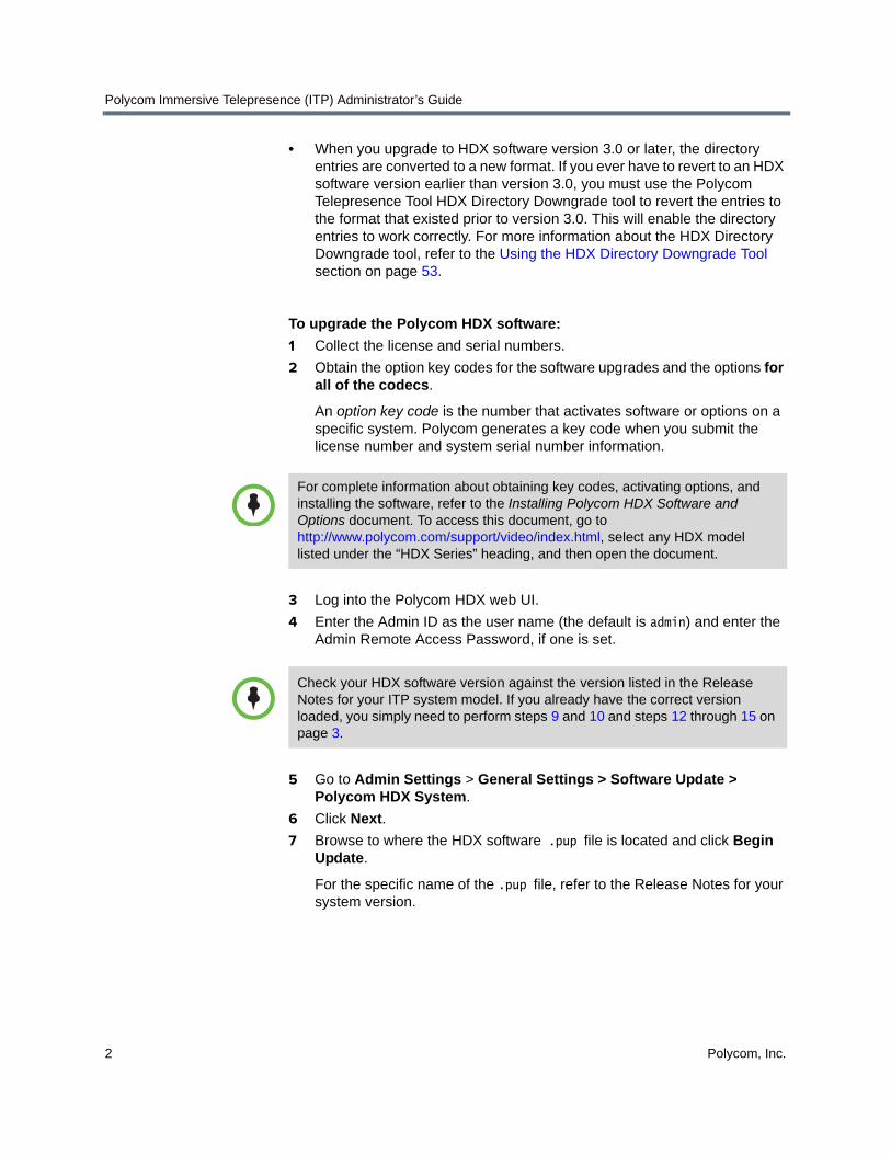
• When you upgrade to HDX software version 3.0 or later, the directory entries are converted to a new format. If you ever have to revert to an HDX software version earlier than version 3.0, you must use the Polycom Telepresence Tool HDX Directory Downgrade tool to revert the entries to the format that existed prior to version 3.0. This will enable the directory entries to work correctly. For more information about the HDX Directory Downgrade tool, refer to the Using the HDX Directory Downgrade Tool section on page 53.
To upgrade the Polycom HDX software:
1 Collect the license and serial numbers.
2 Obtain the option key codes for the software upgrades and the options for all of the codecs.
An option key code is the number that activates software or options on a specific system. Polycom generates a key code when you submit the license number and system serial number information.
3 Log into the Polycom HDX web UI.
4 Enter the Admin ID as the user name (the default is admin) and enter the Admin Remote Access Password, if one is set.
5 Go to Admin Settings > General Settings > Software Update > Polycom HDX System.
6 Click Next.
7 Browse to where the HDX software .pup file is located and click Begin Update.
For the specific name of the .pup file, refer to the Release Notes for your system version.
For complete information about obtaining key codes, activating options, and installing the software, refer to the Installing Polycom HDX Software and Options document. To access this document, go to http://www.polycom.com/support/video/index.html, select any HDX model listed under the “HDX Series” heading, and then open the document.
Check your HDX software version against the version listed in the Release Notes for your ITP system model. If you already have the correct version loaded, you simply need to perform steps 9 and 10 and steps 12 through 15 on page 3.

Configuring the HDX Codecs and the System Controller
Polycom, Inc. 3
8 On the Software Update screens:
a Select Typical as the update type and click Next.
b Click Next.
c Remove the check mark from the Sample Sites in Directory field (leave the other fields checked), and then click Next.
d Click Next to start the update.
For more information about the HDX software, refer to the Polycom HDX documentation.
9 Enter the option key:
a When the codec has finished rebooting, go to Admin Settings > General Settings > Options in the web UI.
b Enter the option key code in the Key field.
The option key enables the options that are required for Immersive Telepresence.
c Click Update.
10 For RPX and OTX systems, if you are not planning to deploy TIP, you must do the following:
a Go to Admin Settings > Network > Call Preference.
b If the SIP and TIP check boxes are selected, clear the check marks from the check boxes.
11 Repeat steps 3 through 10 for the remaining codecs.
12 Go to Admin Settings > General Settings > Security > Security Settings.
13 If the Enable Sessions List check box appears on the screen, clear the check mark from the check box.
14 Click Update.
15 Repeat steps 12 through 14 for the remaining codecs.
Setting the Date and Time
You must set the correct date and time on the HDX codecs in order for the calendaring feature and the sleep timer settings to work properly. (For more information about calendaring, see the Enabling Polycom Conferencing for Microsoft Outlook section on page 98. For more information about setting the sleep timers in the System_Config.ini file, see the Editing the System_Config.ini File section on page 21.)
To set the date and time:
1 Log into the Polycom HDX web UI.
2 Go to Admin Settings > General Settings > Date and Time.

Polycom Immersive Telepresence (ITP) Administrator’s Guide
4 Polycom, Inc.
3 In the Time Server field, select Auto or Manual.
4 If you select Manual, the Time Server Address field appears, and you must enter the IP address of a publicly available time server.
5 Verify the information in the remaining fields on the screen:
a The Current Date and Current Time fields display information obtained from the time server. These fields are grayed out when you select Auto or Manual.
b In the Auto Adjust for Daylight Saving Time field, ensure that the box is checked if you want the system clock to automatically change for daylight saving time.
c Ensure that the Time Zone field displays the correct information.
6 Click Update.
7 Repeat steps 1 through 6 for the remaining codecs.
Note that, although the calendaring and sleep settings rely on the date and time set for the Primary codec only, you should repeat steps 1 through 6 for the remaining codecs so that the date and time from all the codecs can be used for diagnostic purposes.
Enabling HDX ITP System Communication
The HDX codecs use the same interface to communicate with each other as the Polycom Touch Control uses to communicate with the Primary HDX. Therefore, whether you have a Polycom Touch Control or a Crestron Touch Panel, you must enable the Polycom Touch Control Pairing feature on each HDX codec within the ITP system in order for the codecs to communicate with each other.
To enable HDX ITP system communication:
1 Log into the Polycom HDX web interface.
2 Go to Admin Settings > Polycom Touch Control.

Configuring the HDX Codecs and the System Controller
Polycom, Inc. 5
3 Select the Allow Polycom Touch Control to Pair with this System check box.
Figure 1-1 HDX Web UI Polycom Touch Control Screen
4 If a pop-up box appears, click OK to continue.
5 Repeat steps 1 through 4 for the remaining codecs.
Configuring the System ControllerThis section describes the tasks you may need to perform to configure the System Controller (also known as the AV2). These tasks include:
• Configuring the LAN
• Connecting to the System Controller
• Upgrading the System Controller firmware
• Loading the System Controller software
Before you can perform any of these tasks, ensure that you have the Crestron® Toolbox application installed. This application is available from Crestron. Note that you may need to register with Crestron in order to download the Toolbox.

Polycom Immersive Telepresence (ITP) Administrator’s Guide
6 Polycom, Inc.
Configuring the LAN
To configure the LAN:
1 Open the Toolbox application and select the System Info icon.
2 On the System Info screen, click the arrow button in the Ethernet field.
Figure 1-2 Ethernet Field on the Toolbox System Info Screen
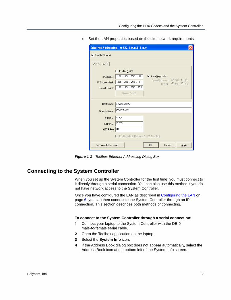
3 In the Ethernet Addressing dialog box:
a Select the Enable Ethernet check box.
b If the system uses DHCP, select the Enable WINS (Requires DHCP Enabled) check box.
Configuring the HDX Codecs and the System Controller
Polycom, Inc. 7
c Set the LAN properties based on the site network requirements.
Figure 1-3 Toolbox Ethernet Addressing Dialog Box
Connecting to the System Controller
When you set up the System Controller for the first time, you must connect to it directly through a serial connection. You can also use this method if you do not have network access to the System Controller.
Once you have configured the LAN as described in Configuring the LAN on page 6, you can then connect to the System Controller through an IP connection. This section describes both methods of connecting.
To connect to the System Controller through a serial connection:
1 Connect your laptop to the System Controller with the DB-9 male-to-female serial cable.
2 Open the Toolbox application on the laptop.
3 Select the System Info icon.
4 If the Address Book dialog box does not appear automatically, select the Address Book icon at the bottom left of the System Info screen.

Polycom Immersive Telepresence (ITP) Administrator’s Guide
8 Polycom, Inc.
5 In the Address Book dialog box, click Add Entry and then specify a name for the System Controller in the Name column.
Figure 1-4 Toolbox Address Book Screen (with RS232Connection Type)
6 Select the following:
a Connection Type: RS232
b Port: Select the appropriate COM port for your laptop
c Baud Rate: Auto-Detect
Leave the rest of the settings at their defaults, as shown in Figure 1-4.
7 Click OK.
The Toolbox will connect to the System Controller.
8 To connect to the Crestron Touch Panel if the site uses one (if the site uses a Polycom Touch Control, skip this step):
a Select Add Entry, and then enter the name of the Touch Panel in the Name column.

Configuring the HDX Codecs and the System Controller
Polycom, Inc. 9
b Select Indirect as the Connection Type.
Figure 1-5 Toolbox Address Book Screen (with Indirect Connection Type)
c Ensure that Cresnet ID and 03 appear in the Device is at field.
d In the Through field, select the name of the System Controller that you entered in step 5.
e Click OK.
To connect to the System Controller through an IP connection:
1 Ensure that the System Controller’s LAN is configured correctly as described in Configuring the LAN on page 6.
2 Open the Toolbox application on the laptop.
3 Select the System Info icon.
4 If the Address Book dialog box does not appear automatically, select the Address Book icon at the bottom left of the System Info screen.
You can connect to the System Controller through an IP connection only if you have first connected to the LAN. If you have not done so, refer to Configuring the LAN on page 6.

Polycom Immersive Telepresence (ITP) Administrator’s Guide
10 Polycom, Inc.
5 In the Address Book dialog box, click the entry you want to connect to over IP.
If the entry is not listed, you must create a new entry as described in step 5 on page 8.
6 Select TCP as the Connection Type.
7 Enter the IP address.
8 Click OK.
The Toolbox will connect to the System Controller.
To connect to a System Controller that is already listed in the Address Book:
1 Open the Toolbox application on the laptop.
2 Select the System Info icon.
3 On the System Info screen, select the System Controller that you want to connect to from the Address Book drop-down list.
Figure 1-6 Address Book Drop-Down on the Toolbox System Info Screen
Configuring the HDX Codecs and the System Controller
Polycom, Inc. 11
Upgrading the System Controller Firmware
To determine which System Controller firmware version should be installed on the system, refer to the Release Notes for your system version.
Confirming the System Controller Firmware Version
To confirm the System Controller firmware version:
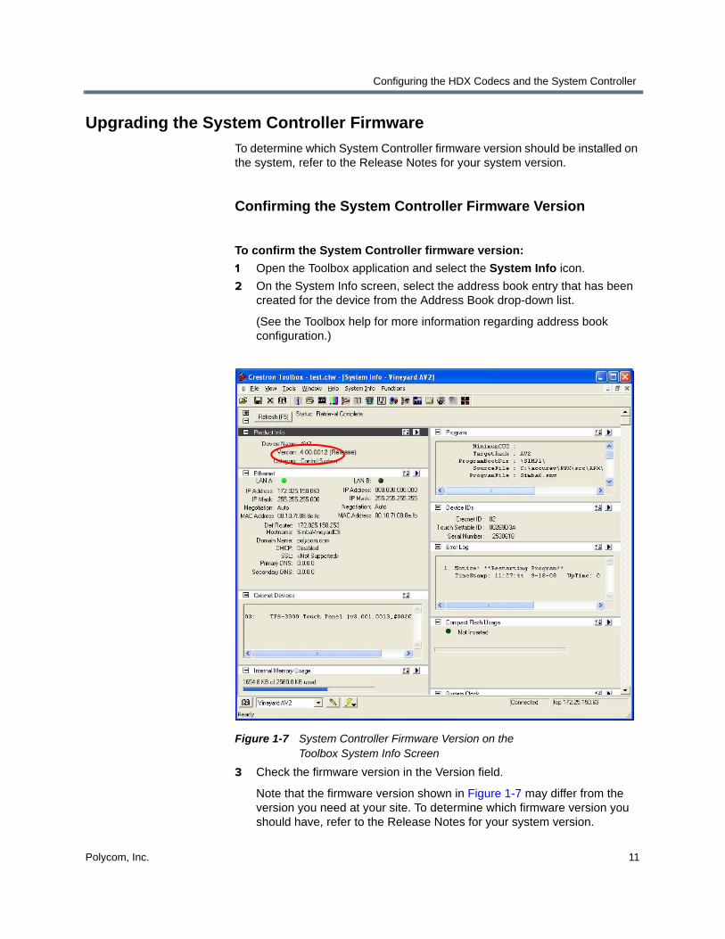
1 Open the Toolbox application and select the System Info icon.
2 On the System Info screen, select the address book entry that has been created for the device from the Address Book drop-down list.
(See the Toolbox help for more information regarding address book configuration.)
Figure 1-7 System Controller Firmware Version on the Toolbox System Info Screen
3 Check the firmware version in the Version field.
Note that the firmware version shown in Figure 1-7 may differ from the version you need at your site. To determine which firmware version you should have, refer to the Release Notes for your system version.

Polycom Immersive Telepresence (ITP) Administrator’s Guide
12 Polycom, Inc.
Downloading the System Controller Firmware
If you do not have the correct firmware version installed on the System Controller, you must upgrade it as described in this section.
To download the System Controller firmware:
1 Open the Toolbox application and select the System Info icon.
2 On the System Info screen, select the address book entry that has been created for the device from the Address Book drop-down list.
(See the Toolbox help for more information regarding address book configuration.)
3 Select Firmware from the Functions menu.
Figure 1-8 Toolbox Firmware Dialog Box
4 Click Browse to find and select the firmware .zip file.
For the specific name of the .zip file, refer to the Release Notes for your system version. Note that you do not have to unzip this file.
5 Click Send to start the upgrade process. The upgrade process should take less than five minutes to complete.
Loading the System Controller Software
To load the System Controller software:
1 Open the Toolbox application and select the System Info icon.
2 On the System Info screen, select the System Controller that you want to connect to from the Address Book drop-down list.

Configuring the HDX Codecs and the System Controller
Polycom, Inc. 13
3 Select Functions > SIMPL Program… to view the SIMPL Program dialog box.
Figure 1-9 Toolbox SIMPL Program Dialog Box
4 Click Browse, and then select the .spz file from the Open File dialog box.
For the specific name of the .zip file that contains the .spz file, refer to the Release Notes for your system version.
5 Click Send to start the transfer.
6 If the dialog box shown in Figure 1-10 appears, click Yes.
Figure 1-10 Toolbox Device Firmware Confirmation Dialog Box

Polycom Immersive Telepresence (ITP) Administrator’s Guide
14 Polycom, Inc.
The System Controller automatically reboots after the transfer. After it reboots, this message appears on the touch screen: Please wait for system startup...

Polycom, Inc. 15
2Loading the Polycom Touch Control or Crestron Touch Panel Software
This chapter describes how to load the Polycom Touch Control operating system and Polycom Touch Control software (for ITP sites with a Polycom Touch Control), as well as how to load the Touch Panel software and upgrade the Touch Panel firmware (for ITP sites with a Crestron Touch Panel supplied by Polycom).
• If the ITP site has a Polycom Touch Control, refer to the following section.
• If the ITP site has a Crestron Touch Panel, refer to the Loading the Crestron Touch Panel Software and Firmware section on page 16.
Loading the Polycom Touch Control Operating System and Software
This section describes how to use a USB storage device to load the Polycom Touch Control operating system and Polycom Touch Control software.
To determine which Polycom Touch Control operating system version and Polycom Touch Control software that should be installed on the system, refer to the Release Notes for your system version.
You must load the latest software for your Polycom Touch Control or Crestron Touch Panel whether you are installing your ITP system straight from the factory or you are upgrading from a previous version.
Polycom Immersive Telepresence (ITP) Administrator’s Guide
16 Polycom, Inc.
To load the Polycom Touch Control operating system and software:
1 Using a standard Windows zip utility, extract all contents from polycom-venus-HDXCtrl-x.x.x-xx.zip and polycom-venus-platform-x.x.x-xx.zip to the root directory of a USB storage device.
When extracting multiple distribution packages to the USB drive, a pop up message might appear asking if you want to overwrite certain files that already exist. Select Yes to All.
2 Connect the USB device to the side of the Polycom Touch Control.
3 From the Home screen, touch Administration and then Updates.
4 Touch Check for Software Updates.
5 Touch Select All Updates or touch only the updates that you want to install.
6 Touch Download and Install Software Updates.
7 Reboot the Crestron System Controller after the installation is complete.
Loading the Crestron Touch Panel Software and Firmware
If your ITP system has a Crestron Touch Panel supplied by Polycom, refer to the steps in this section for information about how to load the Touch Panel software and upgrade the Touch Panel firmware.
Loading the Touch Panel Software
To load the Touch Panel software:
1 Open the Toolbox application and select the System Info icon.
2 On the System Info screen, select the address book entry that has been created for the Touch Panel from the Address Book drop-down list.

Loading the Polycom Touch Control or Crestron Touch Panel Software
Polycom, Inc. 17
3 Select Functions > Project... to view the Project dialog box.
Figure 2-1 Toolbox Project Dialog Box
4 Click Browse and select the.vtz file.
For the specific name of the .zip file that contains the .vtz file, refer to the Release Notes for your system version.
5 Click Send to start the transfer.
6 If you are loading the software onto a 6-inch Touch Panel (for TPX only), the dialog box shown in Figure 2-2 appears, and you should click Yes.
Figure 2-2 Toolbox Device Type Confirmation Dialog Box
Wait for the transfer to complete, which may take about 40 minutes.

Polycom Immersive Telepresence (ITP) Administrator’s Guide
18 Polycom, Inc.
Upgrading the Touch Panel Firmware
To determine which Touch Panel firmware version should be installed on the system, refer to the Release Notes for your system version.
Confirming the Touch Panel Firmware Version
To confirm the Touch Panel firmware version:
1 Open the Toolbox application and select the System Info icon.
2 On the System Info screen, select the address book entry that has been created for the Touch Panel from the Address Book drop-down list.
3 Check the firmware version in the Version field.
Note that the firmware version shown in Figure 2-3 may differ from the version you need at your installation site. To determine which firmware version you should have, refer to the Release Notes for your system version.
Figure 2-3 Version Field on Toolbox System Info Screen

Loading the Polycom Touch Control or Crestron Touch Panel Software
Polycom, Inc. 19
Downloading the Touch Panel Firmware
If you do not have the correct firmware version installed on the Touch Panel, you must upgrade it as described in this section.
To download the Touch Panel firmware:
1 Open the Toolbox application and select the System Info icon.
2 On the System Info screen, select the address book entry that has been created for the Touch Panel from the Address Book drop-down list.
3 Select Firmware from the Functions menu.
Figure 2-4 Firmware Dialog Box
4 Click Browse to find and select the .zip file.
For the specific name of the .zip file, refer to the Release Notes for your system version. Note that you do not have to unzip this file.
5 Click Send to start the upgrade process.
The upgrade process should take less than 5 minutes to complete.

Polycom Immersive Telepresence (ITP) Administrator’s Guide
20 Polycom, Inc.

Polycom, Inc. 21
3Configuring System Parameters with the System_Config.ini File
Some system parameters can be reconfigured by the IT administrator, VNOC personnel, or Polycom-certified product installer. These parameters are stored in a .ini file, called System_Config.ini, which resides on the System Controller internal flash memory.
By editing this file as described in this chapter, you can configure parameters such as the model of the system, the HDX password, and the Do Not Disturb timer. You can also configure optional parameters, such as the video format preference.
Editing the System_Config.ini File
To edit the System_Config.ini file:
1 Open the Toolbox application and select the System Info icon.
2 On the System Info screen, select the address book entry that has been created for the System Controller from the Address Book drop-down list.
In RPX, TPX, and ATX versions earlier than version 2.5, the System_Config.ini file contained additional parameters, such as video numbers, audio numbers, and the Help Desk number. These parameters are now configured in the telepresence system’s Primary HDX codec. For more information, refer to Chapter 7, Configuring System Parameters with the System_Config.ini File.

Polycom Immersive Telepresence (ITP) Administrator’s Guide
22 Polycom, Inc.
3 Select the File Manager icon.
Figure 3-1 Toolbox File Manager Screen
4 Expand the Internal Flash directory and select the USER folder.
5 Right-click the.ini file and select Send to... to send it wherever you want.
6 Open the System_Config.ini file in a text editor.
Use a flat-text editor, such as Notepad, since word processing software may inadvertently add unnecessary data into the file.
When you first open the System_Config.ini file, it contains the following fields:
SystemName: SystemModel: HDXpassword:
AfterHours:WeekStart=MondayWeekEnd=FridayMorningHour=8AMEveningHour=6PMDayTimeSleepTimer=240AfterHoursSleepTimer=60
DoNotDisturbTimer=0
Options:EndOptions

Configuring System Parameters with the System_Config.ini File
Polycom, Inc. 23
7 Edit the System_Config.ini file as needed. Keep the following in mind when editing the file:
— Avoid including any unnecessary spaces or characters.
— Do not edit the field names themselves. This will cause system malfunction.
— The SystemName field is not used elsewhere, but can help you identify each particular system.
— The SystemModel field enables you to specify the model.
Be sure that this field displays the correct model. The available options, in alphabetical order, are:
ATX 300 OTX 100OTX 300RPX 200RPX 204RPX 204MRPX 208RPX 208MRPX 210RPX 210MRPX 210M+RPX 218RPX 218MRPX 400RPX 408RPX 408MRPX 418RPX 418MRPX 428RPX 428MTPX 204MTPX 306M
— If the HDX Primary codec has a password, enter it in the HDXpassword field. When entering the password:
» Do not enter a space after the colon or after the password! For example, if the password is password1, the field should look like this: HDXpassword:password1.
» Make sure that the password you enter is the same as the password for the codecs. If not, communication between the System Controller and the codecs will fail and there will be no indication as to what caused the issue.
Polycom Immersive Telepresence (ITP) Administrator’s Guide
24 Polycom, Inc.
— If you want to specify a call speed, enter the DefaultCallSpeed parameter below the HDXpassword field. Entering a call speed in the System_Config.ini file will force the system to override the preferred call speed set in the HDX Call Preference screen and use the one specified here. (For more information about setting the call speed, see the note on page 47.)
The format for this parameter is DefaultCallSpeed:<speed>, where <speed> must be one of the following:
1536 or 1.5MB1920 or 2MB3072 or 3MB4096 or 4MB6144 or 6MB
— AfterHours settings should indicate times during the week when the system is in use the most.
» Acceptable entries for WeekStart and WeekEnd are Sunday, Monday, Tuesday, Wednesday, Thursday, Friday, and Saturday. Do not abbreviate.
» MorningHour and EveningHour should be whole hour times (for example, 8:43 will not be accepted).
» Enter the SleepTimer parameter as minutes. Typically, you should accept the default values.
— Do Not Disturb prevents unused codecs from accepting any incoming calls. In the DoNotDisturbTimer field, enter the time (in seconds) after which Do Not Disturb is activated.
You can enter a value between 10 and 300, or enter 0 if you want to disable this feature.

Configuring System Parameters with the System_Config.ini File
Polycom, Inc. 25
8 Edit the Options field as needed to indicate which optional features the system is using. The following options are available:
— UseClassicUI
— VideoFormatPreference
— UseIntegratedDocCam
— UseAuxContentInput
— AuxContentSourceType
— AuxContentLabel
— DocCamTextUI
— UseContentOffCall
— UseMonitorLifts
— AutoLiftMode
— DisableEnergySave
— UseCameraViews
For complete information about these options, see Enabling Optional Features on page 26.
The following is an example of how the Options section of the System_Config.ini file would look like with some of these options enabled:
Options:UseClassicUI=1UseAuxContentInput=1AuxContentLabel=DocCamVideoFormatPreference=1080p30EndOptions
9 Save the System_Config.ini file.
Downloading the System_Config.ini File onto the System Controller
To download the System_Config.ini file onto the System Controller:
1 Open the Toolbox application and select the System Info icon.
2 On the System Info screen, select the address book entry that has been created for the System Controller from the Address Book drop-down list.
3 Select the File Manager icon.
4 Expand the Internal Flash directory and select the USER folder.

Polycom Immersive Telepresence (ITP) Administrator’s Guide
26 Polycom, Inc.
5 Drag and drop the System_Config.ini file into the Toolbox File Manager window to download the file.
Before you proceed, check the timestamp for the file on the Toolbox File Manager screen. If the timestamp did not change, you may need to compact the file system. To do so, click the right arrow on the Internal Memory Usage section of the Toolbox System Info screen, and then select Compact.
6 Reboot the System Controller:
a Select the System Info icon.
b On the System Info screen, select Device Reset from the Functions menu.
Enabling Optional FeaturesAll of the ITP solutions offer optional features that you can enable using the System_Config.ini file. This section describes these optional features. For more information about editing the System_Config.ini file, refer to page 25.
Selecting the Enhanced or the Classic User Interface
This optional feature is available with:
The UseClassicUI parameter enables you to select either the Enhanced user interface or the Classic user interface for the Crestron Touch Panel.
• Enhanced UI: Enables users to perform all of the basic tasks needed to participate in a telepresence conference, such as making calls, answering calls, hanging up, controlling audio, and sharing content. The Enhanced UI also provides users with access to additional calling functionality, such as Polycom Meeting Composer™ and advanced directory searching.
ITP SolutionPolycom Touch
ControlCrestron Touch
Panel
RPX —
OTX —
TPX —
ATX 300 (with the non-customizable Polycom
GUI)
—
Configuring System Parameters with the System_Config.ini File
Polycom, Inc. 27
• Classic UI: Enables users to perform the same basic conferencing tasks as the Enhanced UI, such as making and answering calls and sharing content. Users will not, however, have access to Meeting Composer and other advanced calling features and will only have access to the local directory.
If you do not set the UseClassicUI parameter in the Options section of the System_Config.ini file, the Enhanced UI is used.
To enable this option for the Classic UI, enter UseClassicUI=1 in the Options section of the System_Config.ini file. To enable this option for the Enhanced UI, enter either UseClassicUI=0 in the Options section of the System_Config.ini file or remove the string altogether.
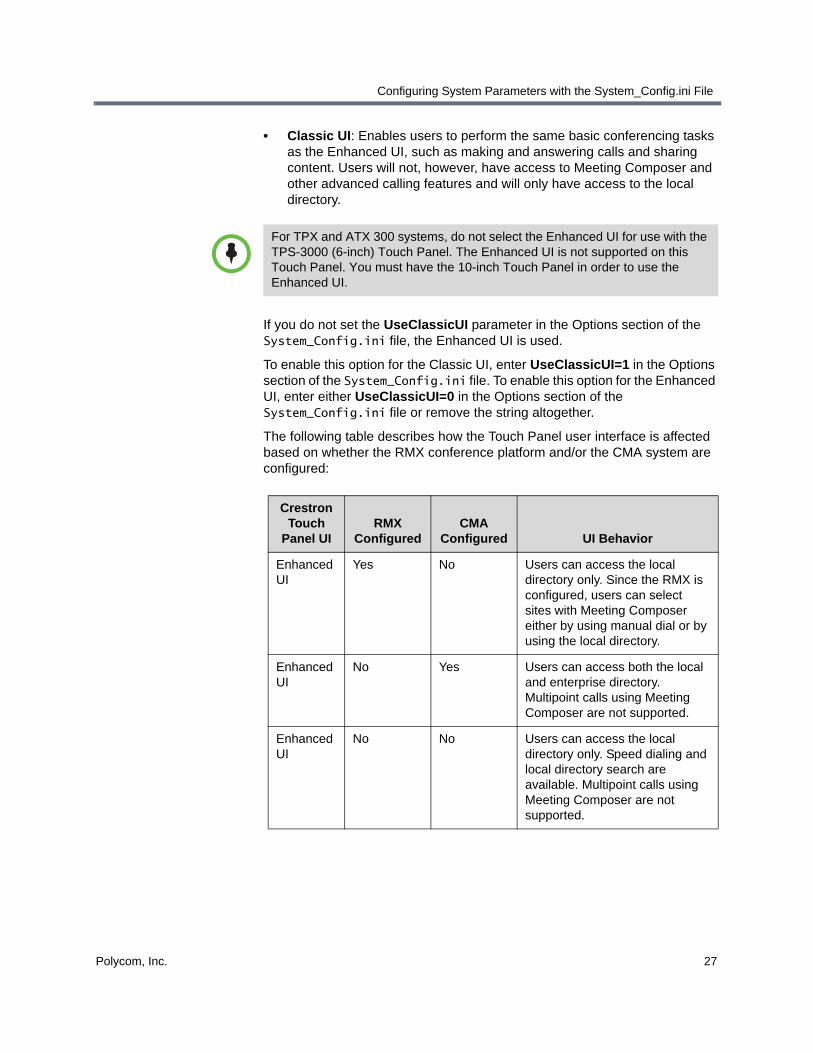
The following table describes how the Touch Panel user interface is affected based on whether the RMX conference platform and/or the CMA system are configured:
For TPX and ATX 300 systems, do not select the Enhanced UI for use with the TPS-3000 (6-inch) Touch Panel. The Enhanced UI is not supported on this Touch Panel. You must have the 10-inch Touch Panel in order to use the Enhanced UI.
Crestron Touch
Panel UIRMX
ConfiguredCMA
Configured UI Behavior
Enhanced UI
Yes No Users can access the local directory only. Since the RMX is configured, users can select sites with Meeting Composer either by using manual dial or by using the local directory.
Enhanced UI
No Yes Users can access both the local and enterprise directory. Multipoint calls using Meeting Composer are not supported.
Enhanced UI
No No Users can access the local directory only. Speed dialing and local directory search are available. Multipoint calls using Meeting Composer are not supported.

Polycom Immersive Telepresence (ITP) Administrator’s Guide
28 Polycom, Inc.
For more information about how to use the Enhanced and Classic UI, refer to the Polycom RPX HD User Guide, the Polycom OTX User Guide, the Polycom TPX HD User Guide, or your particular ATX User Guide.
Enhanced UI
Yes Yes Users can access both the local and enterprise directory, and can search and browse both directories. Multipoint calls using Meeting Composer are supported.
Classic UI Not applicable
Not applicable
RMX and CMA configuration have no impact on the Classic UI behavior. Speed dialing is available. Multipoint calls using Meeting Composer are not supported.
Crestron Touch
Panel UIRMX
ConfiguredCMA
Configured UI Behavior

Configuring System Parameters with the System_Config.ini File
Polycom, Inc. 29
Selecting the Video Format Preference
Selecting the video format preference is an optional feature and is available with the following ITP solutions:
The VideoFormatPreference parameter enables you to set either 720p60 or 1080p30 as the default selection for video quality. If you do not set this parameter in the Options section of the System_Config.ini file, 1080p30 is typically used.
Note that any user who has access to the Admin screen can override the VideoFormatPreference setting for a particular call by using the 720p60 and 1080p30 buttons on the Admin screen prior to placing the call. If, however, the System Controller is rebooted, the video format preference will revert to the setting specified in the System_Config.ini file or, if nothing is specified in the file, 1080p30 will be used.
To enable this option for 1080p30, enter VideoFormatPreference=1080p30 in the Options section of the System_Config.ini file. To enable this option for 720p60, enter VideoFormatPreference=720p60 in the Options section of the System_Config.ini file.
ITP SolutionPolycom Touch
ControlCrestron Touch
Panel
RPX
OTX
TPX
ATX 300 (with the non-customizable Polycom
GUI)
Polycom Immersive Telepresence (ITP) Administrator’s Guide
30 Polycom, Inc.
Enabling the Document Camera
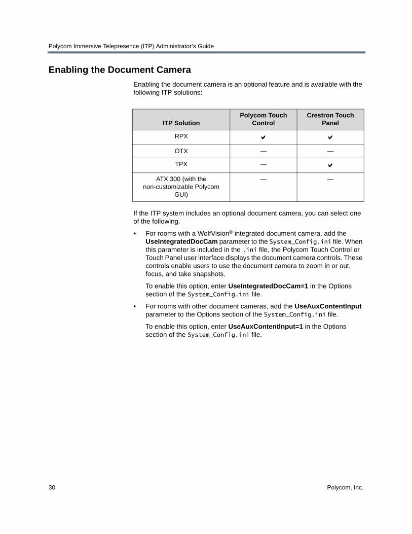
Enabling the document camera is an optional feature and is available with the following ITP solutions:
If the ITP system includes an optional document camera, you can select one of the following.
• For rooms with a WolfVision® integrated document camera, add the UseIntegratedDocCam parameter to the System_Config.ini file. When this parameter is included in the .ini file, the Polycom Touch Control or Touch Panel user interface displays the document camera controls. These controls enable users to use the document camera to zoom in or out, focus, and take snapshots.
To enable this option, enter UseIntegratedDocCam=1 in the Options section of the System_Config.ini file.
• For rooms with other document cameras, add the UseAuxContentInput parameter to the Options section of the System_Config.ini file.
To enable this option, enter UseAuxContentInput=1 in the Options section of the System_Config.ini file.
ITP SolutionPolycom Touch
ControlCrestron Touch
Panel
RPX
OTX — —
TPX —
ATX 300 (with the non-customizable Polycom
GUI)
— —

Configuring System Parameters with the System_Config.ini File
Polycom, Inc. 31
Selecting the Document Camera or the PC as the Content Source
Selecting the document camera or the PC as the content source is an optional feature and is available with the following ITP solution:
RPX rooms may have a document camera as an auxiliary content source or they may have a PC. You must indicate which one each particular room has by adding the AuxContentSourceType parameter to the System_Config.ini file.
If the RPX room has a document camera, enter AuxContentSourceType=DocCam in the Options section of the System_Config.ini file. If the RPX room has a PC, enter AuxContentSourceType=PC in the Options section of the System_Config.ini file.
ITP SolutionPolycom Touch
ControlCrestron Touch
Panel
RPX
OTX — —
TPX — —
ATX 300 (with the non-customizable Polycom
GUI)
— —
Polycom Immersive Telepresence (ITP) Administrator’s Guide
32 Polycom, Inc.
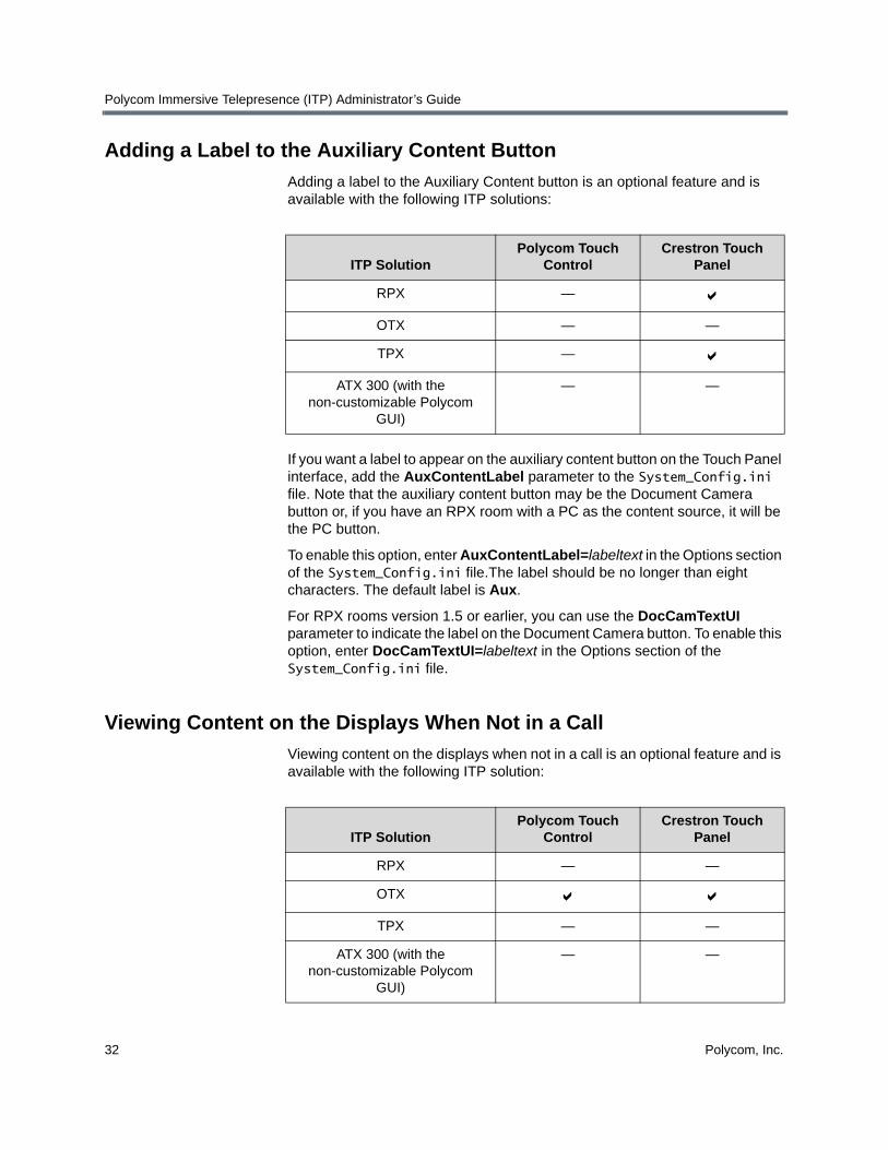
Adding a Label to the Auxiliary Content Button
Adding a label to the Auxiliary Content button is an optional feature and is available with the following ITP solutions:
If you want a label to appear on the auxiliary content button on the Touch Panel interface, add the AuxContentLabel parameter to the System_Config.ini file. Note that the auxiliary content button may be the Document Camera button or, if you have an RPX room with a PC as the content source, it will be the PC button.
To enable this option, enter AuxContentLabel=labeltext in the Options section of the System_Config.ini file.The label should be no longer than eight characters. The default label is Aux.
For RPX rooms version 1.5 or earlier, you can use the DocCamTextUI parameter to indicate the label on the Document Camera button. To enable this option, enter DocCamTextUI=labeltext in the Options section of the System_Config.ini file.
Viewing Content on the Displays When Not in a Call
Viewing content on the displays when not in a call is an optional feature and is available with the following ITP solution:
ITP SolutionPolycom Touch
ControlCrestron Touch
Panel
RPX —
OTX — —
TPX —
ATX 300 (with the non-customizable Polycom
GUI)
— —
ITP SolutionPolycom Touch
ControlCrestron Touch
Panel
RPX — —
OTX
TPX — —
ATX 300 (with the non-customizable Polycom
GUI)
— —
Configuring System Parameters with the System_Config.ini File
Polycom, Inc. 33
If you want the OTX system users to see content on the display(s) at the front of the room when they are not in a call, you can enable the UseContentOffCall parameter in the System_Config.ini file. When set, this parameter enables content from either a local laptop or a local document camera to automatically appear on the front display(s) as well as on the tabletop content monitors when the OTX is not in a call.
To enable content to appear on the display(s) when not in a call, enter UseContentOffCall=1 in the Options section of the System_Config.ini file. To disable this option, either enter UseContentOffCall=0 in the Options section of the System_Config.ini file or remove the string altogether.
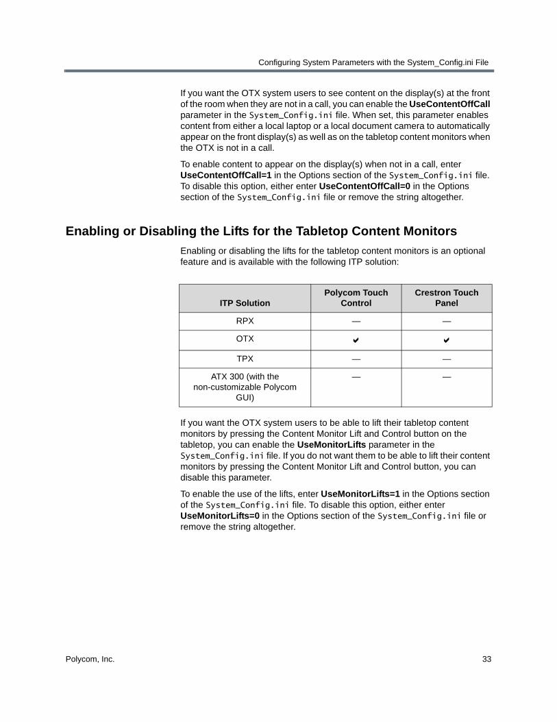
Enabling or Disabling the Lifts for the Tabletop Content Monitors
Enabling or disabling the lifts for the tabletop content monitors is an optional feature and is available with the following ITP solution:
If you want the OTX system users to be able to lift their tabletop content monitors by pressing the Content Monitor Lift and Control button on the tabletop, you can enable the UseMonitorLifts parameter in the System_Config.ini file. If you do not want them to be able to lift their content monitors by pressing the Content Monitor Lift and Control button, you can disable this parameter.
To enable the use of the lifts, enter UseMonitorLifts=1 in the Options section of the System_Config.ini file. To disable this option, either enter UseMonitorLifts=0 in the Options section of the System_Config.ini file or remove the string altogether.
ITP SolutionPolycom Touch
ControlCrestron Touch
Panel
RPX — —
OTX
TPX — —
ATX 300 (with the non-customizable Polycom
GUI)
— —
Polycom Immersive Telepresence (ITP) Administrator’s Guide
34 Polycom, Inc.
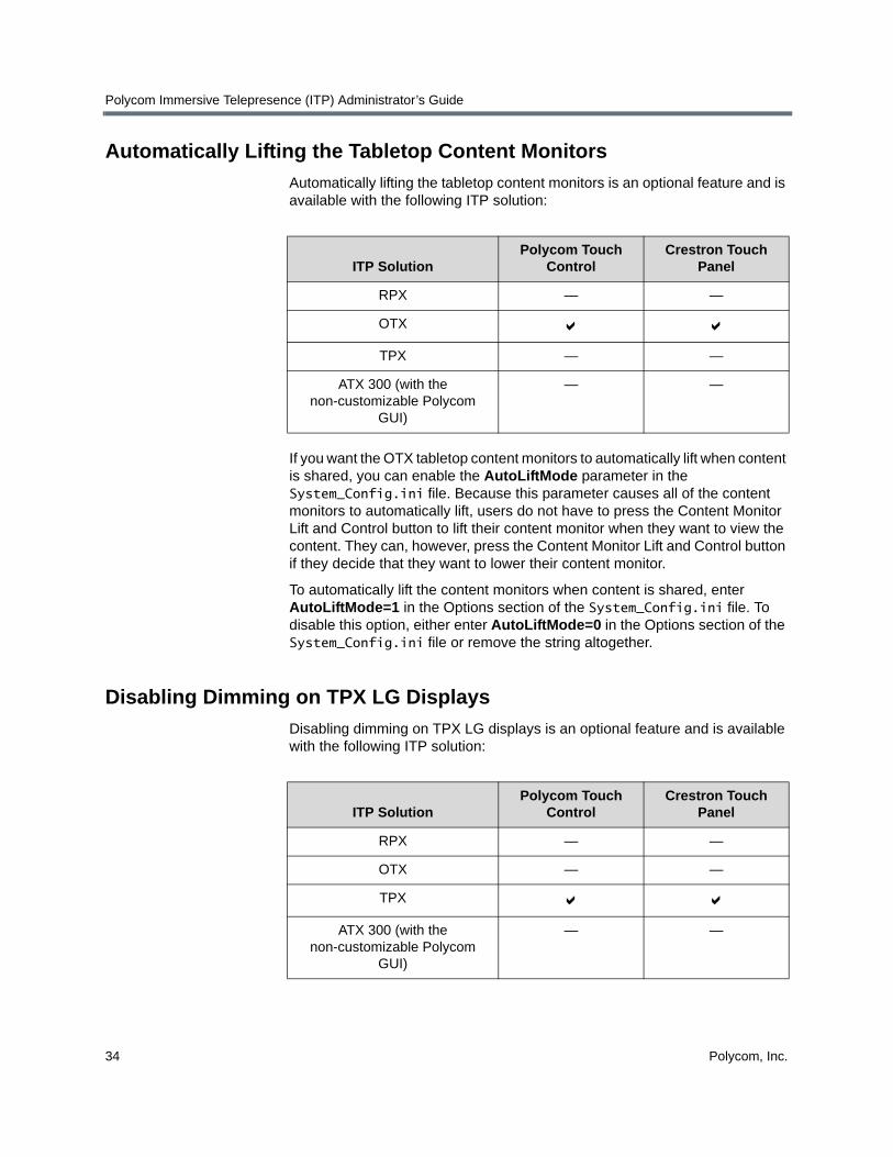
Automatically Lifting the Tabletop Content Monitors
Automatically lifting the tabletop content monitors is an optional feature and is available with the following ITP solution:
If you want the OTX tabletop content monitors to automatically lift when content is shared, you can enable the AutoLiftMode parameter in the System_Config.ini file. Because this parameter causes all of the content monitors to automatically lift, users do not have to press the Content Monitor Lift and Control button to lift their content monitor when they want to view the content. They can, however, press the Content Monitor Lift and Control button if they decide that they want to lower their content monitor.
To automatically lift the content monitors when content is shared, enter AutoLiftMode=1 in the Options section of the System_Config.ini file. To disable this option, either enter AutoLiftMode=0 in the Options section of the System_Config.ini file or remove the string altogether.
Disabling Dimming on TPX LG Displays
Disabling dimming on TPX LG displays is an optional feature and is available with the following ITP solution:
ITP SolutionPolycom Touch
ControlCrestron Touch
Panel
RPX — —
OTX
TPX — —
ATX 300 (with the non-customizable Polycom
GUI)
— —
ITP SolutionPolycom Touch
ControlCrestron Touch
Panel
RPX — —
OTX — —
TPX
ATX 300 (with the non-customizable Polycom
GUI)
— —
Configuring System Parameters with the System_Config.ini File
Polycom, Inc. 35
TPX HD 306M systems, version 2.6 or later, with LG Electronics® displays offer an energy-saving feature. This feature dims the displays when there is no video motion on a particular display for five minutes. For example, if only two participants are in a video call and are seated at the two center seats at the main table, the left and right displays will dim after five minutes if there is no motion on these two displays.
To disable this feature so that no dimming occurs, enter DisableEnergySave=1 in the Options section of the System_Config.ini file. To allow the dimming to occur, either enter DisableEnergySave=0 in the Options section of the System_Config.ini file or remove the string altogether.
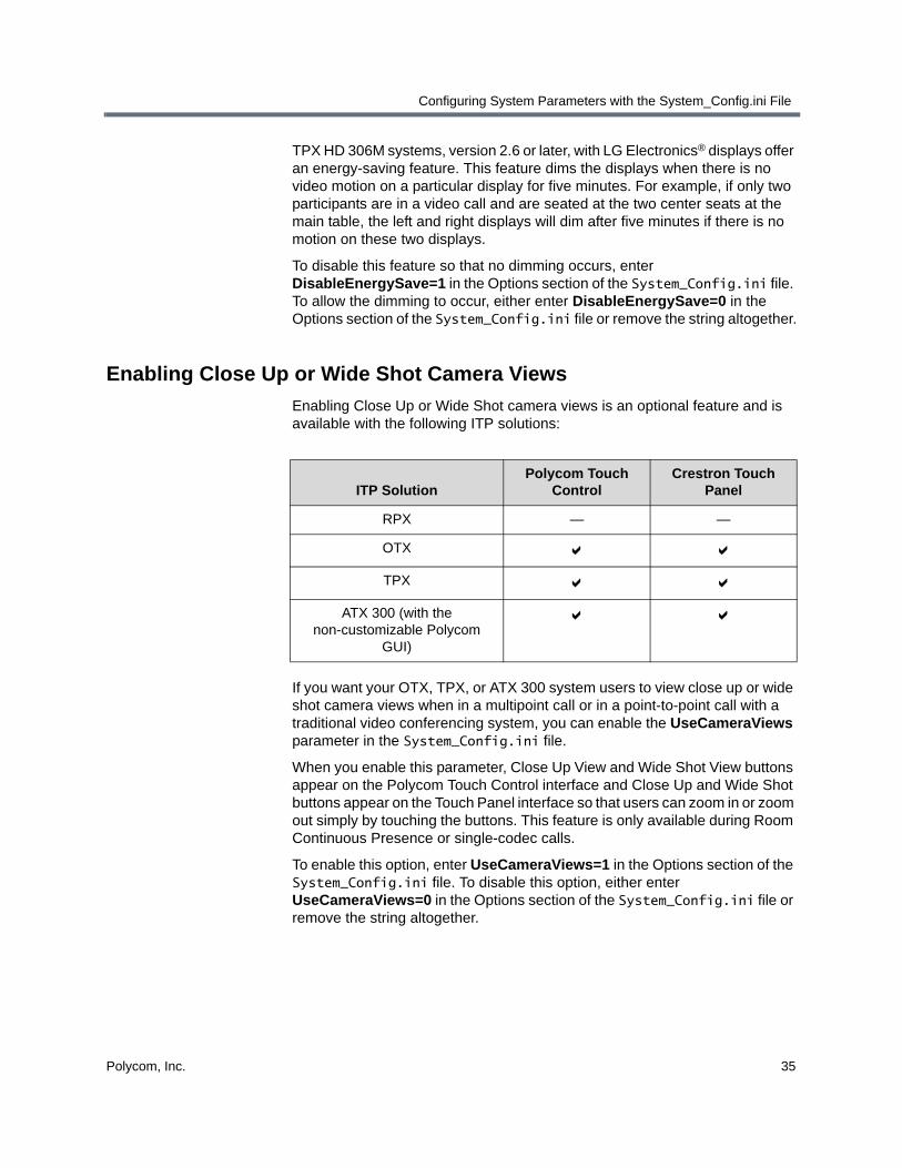
Enabling Close Up or Wide Shot Camera Views
Enabling Close Up or Wide Shot camera views is an optional feature and is available with the following ITP solutions:
If you want your OTX, TPX, or ATX 300 system users to view close up or wide shot camera views when in a multipoint call or in a point-to-point call with a traditional video conferencing system, you can enable the UseCameraViews parameter in the System_Config.ini file.
When you enable this parameter, Close Up View and Wide Shot View buttons appear on the Polycom Touch Control interface and Close Up and Wide Shot buttons appear on the Touch Panel interface so that users can zoom in or zoom out simply by touching the buttons. This feature is only available during Room Continuous Presence or single-codec calls.
To enable this option, enter UseCameraViews=1 in the Options section of the System_Config.ini file. To disable this option, either enter UseCameraViews=0 in the Options section of the System_Config.ini file or remove the string altogether.
ITP SolutionPolycom Touch
ControlCrestron Touch
Panel
RPX — —
OTX
TPX
ATX 300 (with the non-customizable Polycom
GUI)

Polycom Immersive Telepresence (ITP) Administrator’s Guide
36 Polycom, Inc.

Polycom, Inc. 37
4Installing and Using the Polycom Telepresence Tool
The Polycom Telepresence Tool is a Windows application that enables administrators, Polycom-authorized technicians, and VNOC personnel to configure the Polycom HDX codecs and the cameras, to take snapshots of the view from the cameras, and to perform other functions.
This chapter describes how to both install and use the Telepresence Tool. If you have already installed the Telepresence Tool, continue on page 38.
Installing the Telepresence Tool
To install the Polycom Telepresence Tool:
1 Ensure that you have network access to the equipment in the RPX, OTX, TPX, or ATX room.
2 Install the TelepresenceTool_xxx.msi file on your local PC.
Ensure that you install the correct TelepresenceTool_xxx.msi for the software loaded at the site. For the specific name of the .msi file, refer to the Release Notes for your system version.
3 On the laptop, double-click the TelepresenceTool_xxx.msi file.
4 Follow the setup wizard, and click Close when you are done.

Polycom Immersive Telepresence (ITP) Administrator’s Guide
38 Polycom, Inc.
Connecting to the Codecs with the Telepresence Tool
To connect to the codecs with the Telepresence Tool:
1 From the Start menu, go to Polycom > Telepresence Tool > Polycom Telepresence Tool.
2 If this is the first time you use the Telepresence Tool, the Select Telepresence Model dialog box appears and you must do the following:
a In the Select Model field, select the RPX, OTX, TPX, or ATX system model.
b In the Select Main Display field, select one of the following:
» For RPX systems, select the appropriate type of projector.
» For OTX and TPX systems, select the appropriate type of display.
Figure 4-1 Telepresence Tool Select Telepresence Model Dialog Box — OTX 100 Example

Installing and Using the Polycom Telepresence Tool
Polycom, Inc. 39
» For ATX, select the video format for the main displays installed in the room. If the video format you want is 720p DVI, select Widescreen - 720p.
Figure 4-2 Telepresence Tool Select Telepresence Model Dialog Box — ATX 300 Example
c In the Select Content Display field, select one of the following:
» For RPX systems, select Standard - VGA 1024x768 for rooms that do not have Orion content monitors or select Widescreen - DVI 1920x1080p for rooms that do have Orion content monitors.
» For OTX systems, select Widescreen - DVI 1920x1080p.
» For TPX systems, select Standard - VGA 1024x768 for rooms that have 4:3 tabletop content monitors or select Widescreen - VGA 1280x720 for rooms that have 16:9 tabletop content monitors.
» For ATX systems, select the video format for the content monitors installed in the room.
d Click OK.
Polycom Immersive Telepresence (ITP) Administrator’s Guide
40 Polycom, Inc.
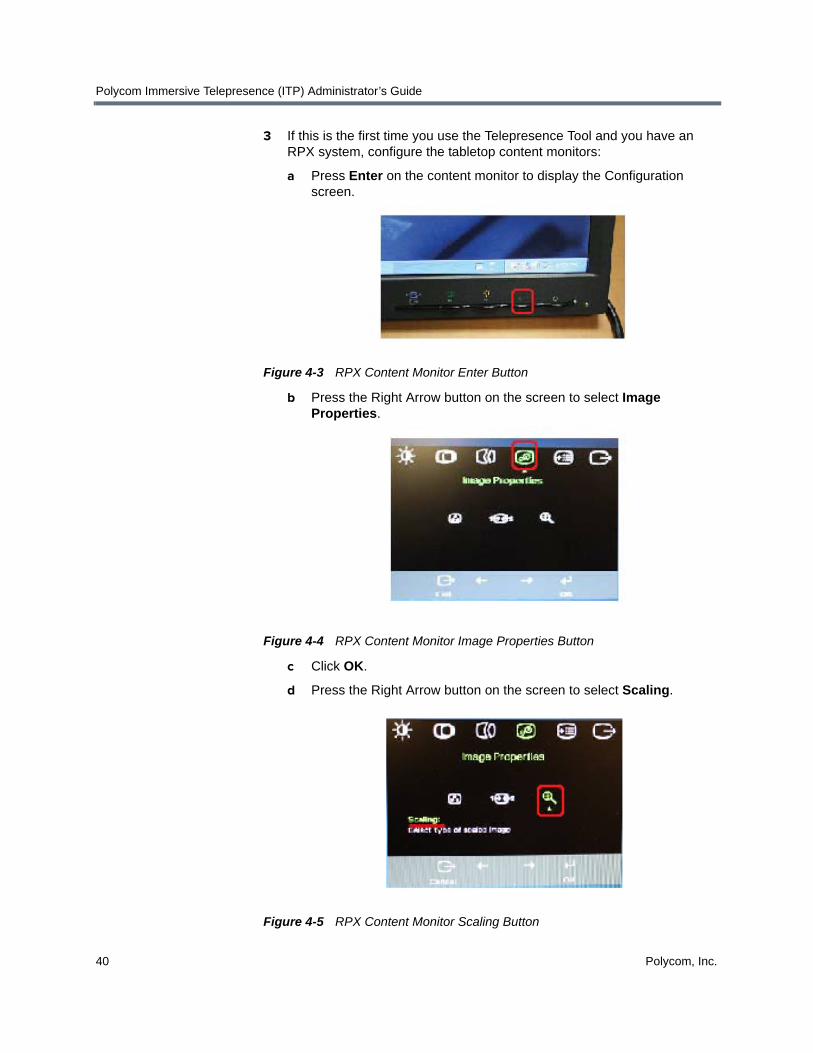
3 If this is the first time you use the Telepresence Tool and you have an RPX system, configure the tabletop content monitors:
a Press Enter on the content monitor to display the Configuration screen.
Figure 4-3 RPX Content Monitor Enter Button
b Press the Right Arrow button on the screen to select Image Properties.
Figure 4-4 RPX Content Monitor Image Properties Button
c Click OK.
d Press the Right Arrow button on the screen to select Scaling.
Figure 4-5 RPX Content Monitor Scaling Button

Installing and Using the Polycom Telepresence Tool
Polycom, Inc. 41
e Click OK.
f Select Full Screen.
Figure 4-6 RPX Content Monitor Full Screen Button
g Click OK.
h If needed, press the Auto Sync button to make the content fill the screen.
Figure 4-7 RPX Content Monitor Auto Sync Button
i Repeat step 3a through 3h for the remaining tabletop content monitors.
4 Connect to the Polycom HDX codecs:
a In the IP Address field, enter the IP address of the codecs.
b In the Password field, enter the password for the codecs in the Password field (if needed).
c In the API Port field, the default is 24. However, if you have a NAT, it may map the API port to a different port. If so, enter the number of the mapped port in the API Port field.
If this is not the first time you use the Telepresence Tool, but the appropriate model name does not appear on the Telepresence Tool Main screen, click Switch Model.

Polycom Immersive Telepresence (ITP) Administrator’s Guide
42 Polycom, Inc.
d In the HTTP Port field, the default is 80. However, if you have a NAT, it may map the HTTP port to a different port. If so, enter the number of the mapped port in the HTTP Port field.
Figure 4-8 Telepresence Tool Main Screen (Before Connection) — RPX 200 Example

Installing and Using the Polycom Telepresence Tool
Polycom, Inc. 43
5 Click Connect All.
The full Telepresence Tool main screen appears as shown in Figure 4-9.
Figure 4-9 Telepresence Tool Main Screen (After Connection) — RPX 200 Example
Once you have connected to the Polycom HDX codecs, you must configure the HDX codecs as described in the following section.
If a codec fails to connect, you may have forgotten to remove the password for that codec (the default password is the serial number of the codec). If you need to remove the password, use the Polycom HDX web UI.

Polycom Immersive Telepresence (ITP) Administrator’s Guide
44 Polycom, Inc.
Configuring the Codecs with the Telepresence ToolThe first time you use the Telepresence Tool, you must configure the HDX codecs.
To configure the codecs with the Telepresence Tool:
1 Ensure that the Telepresence Tool is launched on the laptop.
2 Click Connect All to connect to the codecs.
3 Click Configure All HDXs on the Telepresence Tool main screen.
The HDX Optional Configuration dialog box appears.
4 If you have an RPX system and the Suite configuration field appears on the HDX Optional Configuration dialog box, select one of the following:
— Select Standard if you have a standard RPX suite.
— Select one of the options listed if you have a custom RPX suite.
Figure 4-10 Telepresence Tool HDX Optional Configuration Dialog BoxSuite Configuration Field for RPX
For more information about installing and using a whiteboard camera with an RPX system, refer to the Installing the White Board Camera in a Polycom RPX Series Suite document (part number 1725-26828-001) that is shipped with the whiteboard camera.

Installing and Using the Polycom Telepresence Tool
Polycom, Inc. 45
5 If you have an OTX system and the Suite configuration field appears on the HDX Optional Configuration dialog box, select one of the following:
— Select Standard if you have a standard OTX system.
— Select OTX 100 compact if you have an OTX 100 Compact system.
Figure 4-11 Telepresence Tool HDX Optional Configuration Dialog BoxSuite Configuration Field for OTX
6 If you have an ATX, the Splash screen on content display field appears on the HDX Optional Configuration dialog box (as shown in Figure 4-13), and you must select one of the following:
— If you do not have plasma displays, select Show if you want the Polycom splash screen to appear on the displays or select Hide if you do not want the Polycom splash screen to appear.
— If you do have plasma displays, Polycom recommends that you select Hide to avoid burning in the splash screen logo.
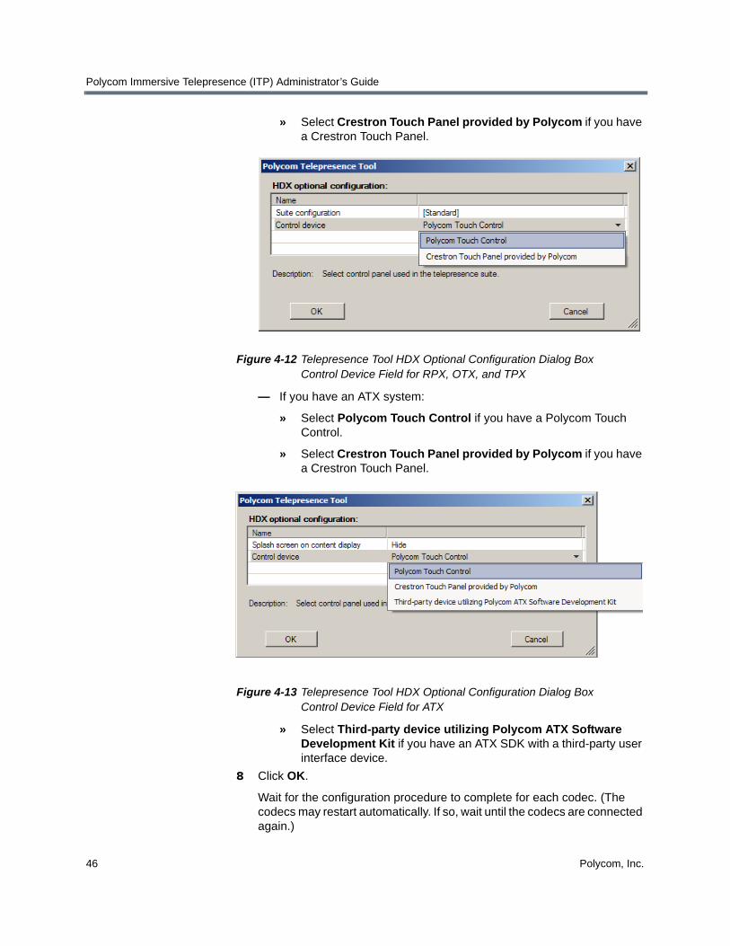
7 In the Control device field on the HDX Optional Configuration dialog box, do the following:
— If you have an RPX, OTX, or TPX system:
» Select Polycom Touch Control if you have a Polycom Touch Control.
Polycom Immersive Telepresence (ITP) Administrator’s Guide
46 Polycom, Inc.
» Select Crestron Touch Panel provided by Polycom if you have a Crestron Touch Panel.
Figure 4-12 Telepresence Tool HDX Optional Configuration Dialog BoxControl Device Field for RPX, OTX, and TPX
— If you have an ATX system:
» Select Polycom Touch Control if you have a Polycom Touch Control.
» Select Crestron Touch Panel provided by Polycom if you have a Crestron Touch Panel.
Figure 4-13 Telepresence Tool HDX Optional Configuration Dialog BoxControl Device Field for ATX
» Select Third-party device utilizing Polycom ATX Software Development Kit if you have an ATX SDK with a third-party user interface device.
8 Click OK.
Wait for the configuration procedure to complete for each codec. (The codecs may restart automatically. If so, wait until the codecs are connected again.)

Installing and Using the Polycom Telepresence Tool
Polycom, Inc. 47
9 When the Telepresence Tool finishes configuring the codecs, you can click View Log if you want to view the log or you can click Close to close the dialog box.
If you click Close, the Start button appears on the Polycom Touch Control. If it does not, reboot the System Controller.
Performing Other Tasks with the Telepresence Tool
The Telepresence Tool enables you to perform a number of different tasks, such as matching and aligning the cameras and verifying the display alignment. You can perform most of the tasks remotely. However, some tasks require that a Polycom-certified support representative be physically present in the telepresence room.
One of the functions of configuring the codecs with the Telepresence Tool is to set the preferred call speed on the HDX Call Preference screen. The preferred call speed is based on the type of codec. For HDX 9004 codecs, the call speed is set to 4 Mbps (4096); for HDX 8000 codecs, the call speed is set to 6 Mbps (6144).
Besides setting the preferred call speed by running the Telepresence Tool, you can also set it:
• Using the DefaultCallSpeed parameter in the System_Config.ini file.
For more information, see page 24.
• On the Admin page.
For more information, see page 124.
• By manually entering it on the HDX Admin Settings > Network > Call Preference screen.
The preferred call speed is used for all outgoing calls unless you set a different call speed for a particular call in one of these ways:
• In the directory entry for that site.
For more information, see page 86 and 88.
• When you place a call through the HDX web UI.
Keep in mind that if you change the call speed and then reboot the System Controller, the preferred call speed will reset to the speed specified in the System_Config.ini file.
Many of the tasks that you can perform with the Telepresence Tool can only be performed after you have paired the Polycom Touch Control with the HDX codec and with the System Controller. For information about how to pair the Polycom Touch Control, refer to Chapter 5.
Polycom Immersive Telepresence (ITP) Administrator’s Guide
48 Polycom, Inc.
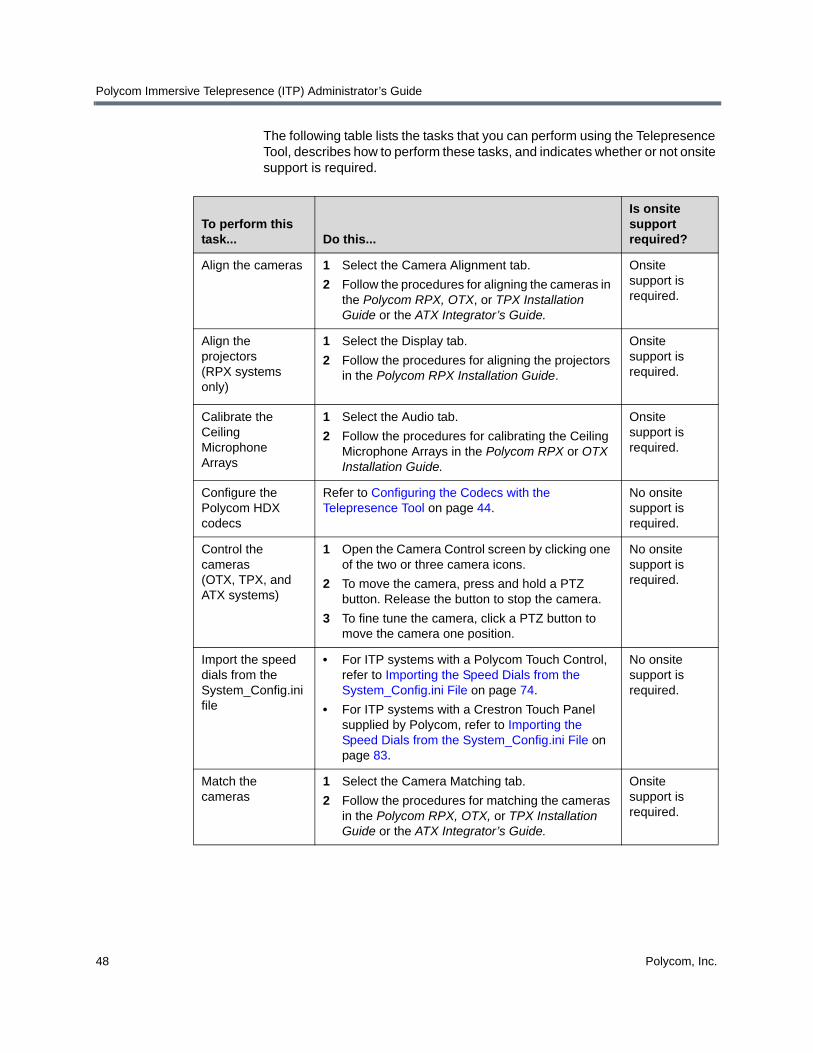
The following table lists the tasks that you can perform using the Telepresence Tool, describes how to perform these tasks, and indicates whether or not onsite support is required.
To perform this task... Do this...
Is onsite support required?
Align the cameras 1 Select the Camera Alignment tab.
2 Follow the procedures for aligning the cameras in the Polycom RPX, OTX, or TPX Installation Guide or the ATX Integrator’s Guide.
Onsite support is required.
Align the projectors (RPX systems only)
1 Select the Display tab.
2 Follow the procedures for aligning the projectors in the Polycom RPX Installation Guide.
Onsite support is required.
Calibrate the Ceiling Microphone Arrays
1 Select the Audio tab.
2 Follow the procedures for calibrating the Ceiling Microphone Arrays in the Polycom RPX or OTX Installation Guide.
Onsite support is required.
Configure the Polycom HDX codecs
Refer to Configuring the Codecs with the Telepresence Tool on page 44.
No onsite support is required.
Control the cameras (OTX, TPX, and ATX systems)
1 Open the Camera Control screen by clicking one of the two or three camera icons.
2 To move the camera, press and hold a PTZ button. Release the button to stop the camera.
3 To fine tune the camera, click a PTZ button to move the camera one position.
No onsite support is required.
Import the speed dials from the System_Config.ini file
• For ITP systems with a Polycom Touch Control, refer to Importing the Speed Dials from the System_Config.ini File on page 74.
• For ITP systems with a Crestron Touch Panel supplied by Polycom, refer to Importing the Speed Dials from the System_Config.ini File on page 83.
No onsite support is required.
Match the cameras
1 Select the Camera Matching tab.
2 Follow the procedures for matching the cameras in the Polycom RPX, OTX, or TPX Installation Guide or the ATX Integrator’s Guide.
Onsite support is required.
Installing and Using the Polycom Telepresence Tool
Polycom, Inc. 49
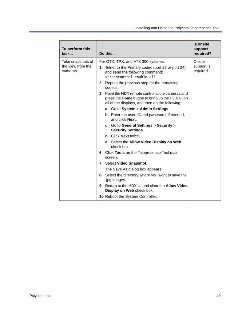
Take snapshots of the view from the cameras
For OTX, TPX, and ATX 300 systems:
1 Telnet to the Primary codec (port 23 or port 24) and send the following command: screencontrol enable all
2 Repeat the previous step for the remaining codecs.
3 Point the HDX remote control at the cameras and press the Home button to bring up the HDX UI on all of the displays, and then do the following:
a Go to System > Admin Settings.
b Enter the user ID and password, if needed, and click Next.
c Go to General Settings > Security > Security Settings.
d Click Next twice.
e Select the Allow Video Display on Web check box.
6 Click Tools on the Telepresence Tool main screen.
7 Select Video Snapshot.
The Save As dialog box appears.
8 Select the directory where you want to save the .jpg images.
9 Return to the HDX UI and clear the Allow Video Display on Web check box.
10 Reboot the System Controller.
Onsite support is required.
To perform this task... Do this...
Is onsite support required?

Polycom Immersive Telepresence (ITP) Administrator’s Guide
50 Polycom, Inc.
Take snapshots of the view from the cameras (continued)
For RPX systems:
1 Telnet to the Primary codec (port 23 or port 24) and send the following command: screencontrol enable all
2 Repeat the previous step for the remaining codecs.
3 Use the Telepresence Tool HDX soft remote to connect to the Primary codec.
4 Click the Home button to bring up the HDX UI, and then do the following:
a Go to System > Admin Settings.
b Enter the user ID and password, if needed, and click Next.
c Go to General Settings > Security > Security Settings.
d Click Next twice.
e Select the Allow Video Display on Web check box.
6 Repeat steps 3 and 4 for the remaining codecs.
7 Click Tools on the Telepresence Tool main screen.
8 Select Video Snapshot.
The Save As dialog box appears.
9 Select the directory where you want to save the .jpg images.
10 Use the HDX soft remote to clear the Allow Video Display on Web check box for all the codecs.
11 Reboot the System Controller.
Onsite support is required.
Update passwords on the HDX codecs
Refer to Updating Passwords on the HDX Codecs on page 51.
No onsite support is required.
Use the address book
Refer to Using the Telepresence Tool Address Book on page 52.
No onsite support is required.
Use the HDX Directory Downgrade tool
Refer to Using the HDX Directory Downgrade Tool on page 53.
No onsite support is required.
View the log Click View Log. No onsite support is required.
To perform this task... Do this...
Is onsite support required?
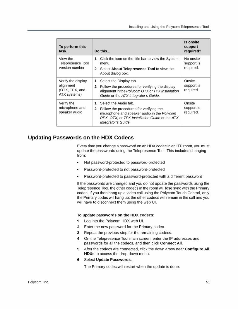
Installing and Using the Polycom Telepresence Tool
Polycom, Inc. 51
Updating Passwords on the HDX Codecs
Every time you change a password on an HDX codec in an ITP room, you must update the passwords using the Telepresence Tool. This includes changing from:
• Not password-protected to password-protected
• Password-protected to not password-protected
• Password-protected to password-protected with a different password
If the passwords are changed and you do not update the passwords using the Telepresence Tool, the other codecs in the room will lose sync with the Primary codec. If you then hang up a video call using the Polycom Touch Control, only the Primary codec will hang up; the other codecs will remain in the call and you will have to disconnect them using the web UI.
To update passwords on the HDX codecs:
1 Log into the Polycom HDX web UI.
2 Enter the new password for the Primary codec.
3 Repeat the previous step for the remaining codecs.
4 On the Telepresence Tool main screen, enter the IP addresses and passwords for all the codecs, and then click Connect All.
5 After the codecs are connected, click the down arrow near Configure All HDXs to access the drop-down menu.
6 Select Update Passwords.
The Primary codec will restart when the update is done.
View the Telepresence Tool version number
1 Click the icon on the title bar to view the System menu.
2 Select About Telepresence Tool to view the About dialog box.
No onsite support is required.
Verify the display alignment (OTX, TPX, and ATX systems)
1 Select the Display tab.
2 Follow the procedures for verifying the display alignment in the Polycom OTX or TPX Installation Guide or the ATX Integrator’s Guide.
Onsite support is required.
Verify the microphone and speaker audio
1 Select the Audio tab.
2 Follow the procedures for verifying the microphone and speaker audio in the Polycom RPX, OTX, or TPX Installation Guide or the ATX Integrator’s Guide.
Onsite support is required.
To perform this task... Do this...
Is onsite support required?

Polycom Immersive Telepresence (ITP) Administrator’s Guide
52 Polycom, Inc.
7 Reboot the System Controller.
8 Open the System_Config.ini file and verify that the HDXPassword field contains the correct password for the Primary codec.
For more information about how to enter a password in the HDXPassword field, refer to page 23.
Using the Telepresence Tool Address Book
The Telepresence Tool address book enables VNOC personnel, Polycom-authorized technicians, and others to quickly and easily connect to ITP sites without having to know the IP addresses for the codecs at the site.
To use the Telepresence Tool address book:
1 Ensure that the Telepresence Tool is launched on the laptop.
2 Click Address Book.
A drop-down menu listing the saved ITP sites appears.
3 Do one of the following:
— To populate the IP Address field with the IP addresses of a site that has already been saved in the address book, select the name of the site from the drop-down menu and press Enter.
— To add the IP addresses of the current site to the address book, enter the site name in the Save As text box, and then click Save As.
Figure 4-14 Telepresence Tool Main Screen — Address Book Drop-Down
— To view the Address Book dialog box, which lists all the ITP sites in the address book, the system model at each site, and the IP addresses of the codecs at each site, click More.
If you then want to populate the IP Address field with the IP addresses from the Address Book dialog box, click Open.
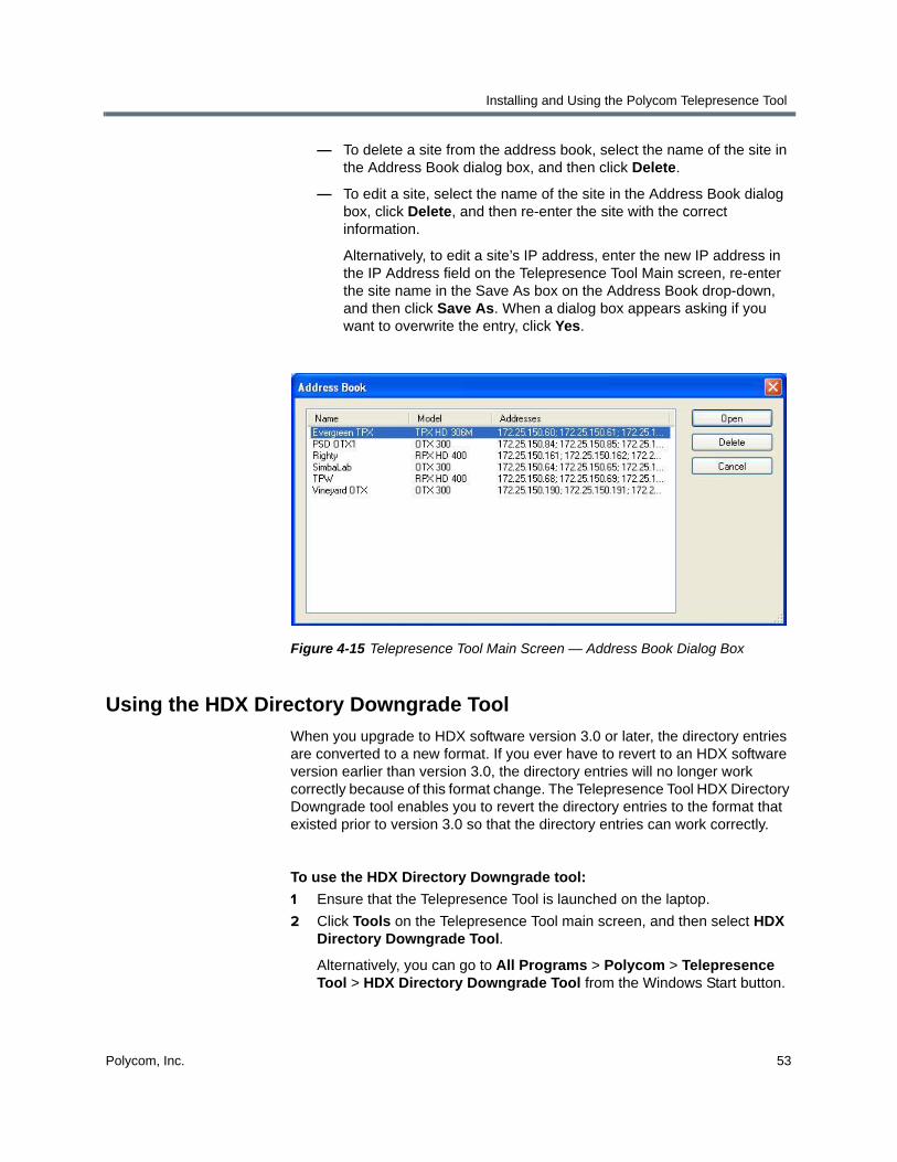
Installing and Using the Polycom Telepresence Tool
Polycom, Inc. 53
— To delete a site from the address book, select the name of the site in the Address Book dialog box, and then click Delete.
— To edit a site, select the name of the site in the Address Book dialog box, click Delete, and then re-enter the site with the correct information.
Alternatively, to edit a site’s IP address, enter the new IP address in the IP Address field on the Telepresence Tool Main screen, re-enter the site name in the Save As box on the Address Book drop-down, and then click Save As. When a dialog box appears asking if you want to overwrite the entry, click Yes.
Figure 4-15 Telepresence Tool Main Screen — Address Book Dialog Box
Using the HDX Directory Downgrade Tool
When you upgrade to HDX software version 3.0 or later, the directory entries are converted to a new format. If you ever have to revert to an HDX software version earlier than version 3.0, the directory entries will no longer work correctly because of this format change. The Telepresence Tool HDX Directory Downgrade tool enables you to revert the directory entries to the format that existed prior to version 3.0 so that the directory entries can work correctly.
To use the HDX Directory Downgrade tool:
1 Ensure that the Telepresence Tool is launched on the laptop.
2 Click Tools on the Telepresence Tool main screen, and then select HDX Directory Downgrade Tool.
Alternatively, you can go to All Programs > Polycom > Telepresence Tool > HDX Directory Downgrade Tool from the Windows Start button.
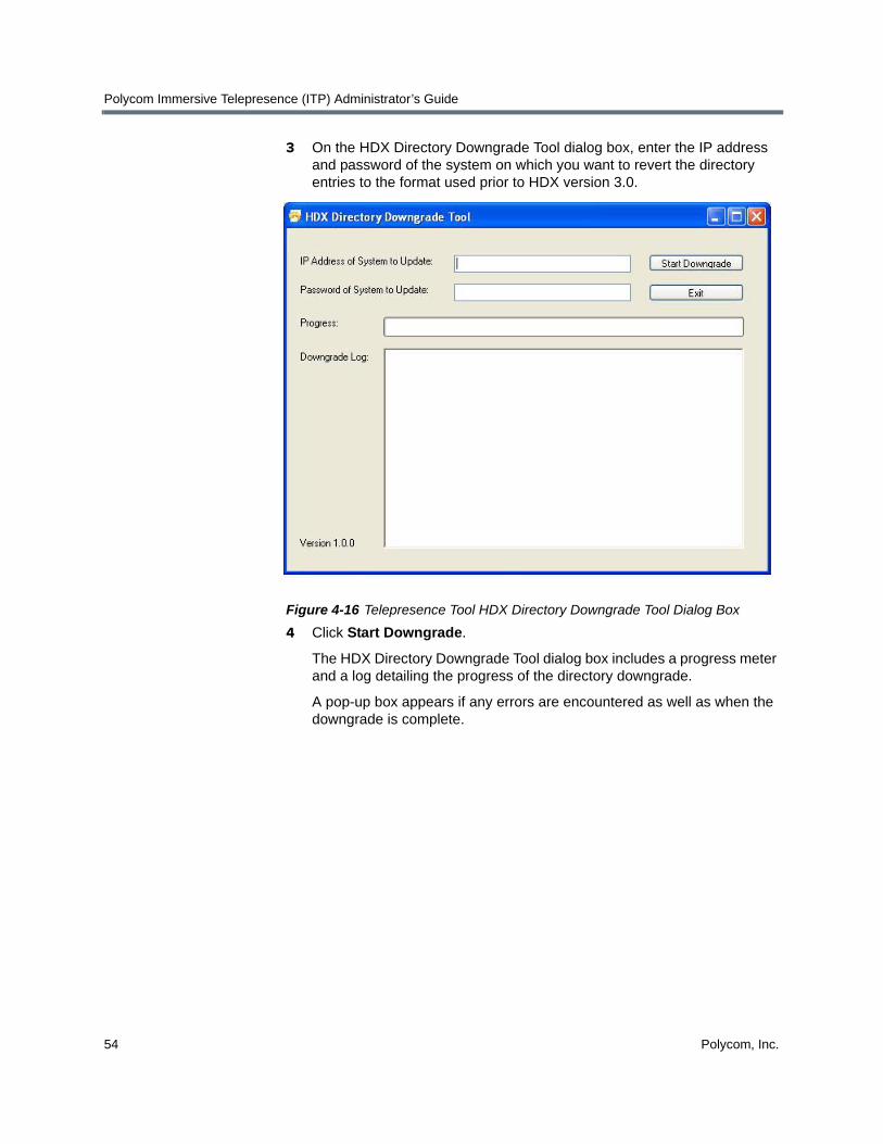
Polycom Immersive Telepresence (ITP) Administrator’s Guide
54 Polycom, Inc.
3 On the HDX Directory Downgrade Tool dialog box, enter the IP address and password of the system on which you want to revert the directory entries to the format used prior to HDX version 3.0.
Figure 4-16 Telepresence Tool HDX Directory Downgrade Tool Dialog Box
4 Click Start Downgrade.
The HDX Directory Downgrade Tool dialog box includes a progress meter and a log detailing the progress of the directory downgrade.
A pop-up box appears if any errors are encountered as well as when the downgrade is complete.

Polycom, Inc. 55
5Pairing the Polycom Touch Control with the HDX Codec and the System Controller
If you have an ITP system with a Polycom Touch Control, you must configure the Polycom Touch Control to pair with the Primary HDX codec and with the System Controller. When you pair the Polycom Touch Control with a particular HDX codec and System Controller, the Polycom Touch Control makes an IP connection to the HDX codec and to the System Controller. If the connection is lost for any reason, the Polycom Touch Control automatically attempts to restore the connection.
Note that if you have an OTX 100 Compact system, you simply have to pair the Polycom Touch Control with the Primary HDX codec since OTX 100 Compact systems do not use a System Controller.
If you have an ITP system with a Crestron Touch Panel provided by Polycom or your Polycom Touch Control is already paired with the HDX codec and the System Controller, skip this chapter and continue with Chapter 6.
Pairing the Polycom Touch Control with the Primary HDX Codec
To pair the Polycom Touch Control with the Primary HDX codec:
1 Log into the Polycom HDX web UI.
2 Go to Admin Settings > Polycom Touch Control.
3 Select the Allow Polycom Touch Control to Pair with this System check box.

Polycom Immersive Telepresence (ITP) Administrator’s Guide
56 Polycom, Inc.
Figure 5-1 HDX Web UI Polycom Touch Control Screen (Unpaired)
4 If a pop-up box appears, click OK to continue.
5 If the Connect to Device screen does not automatically appear on the Polycom Touch Control, do the following:
a Touch System on page 2 of the Polycom Touch Control Home screen.
b Touch the HDX System tab.
The Device Connection Status screen appears.
c Touch .
d Touch View Pairing Settings.
e Enter the Admin ID and password.
The default Admin ID is admin. The default password is 456.
f Touch Done.
The Connect to Device screen appears.
6 If HDX System does not appear in the Device field on the Connect to Device screen, touch the down arrow on the Device field to view the Device list, and then touch HDX System.
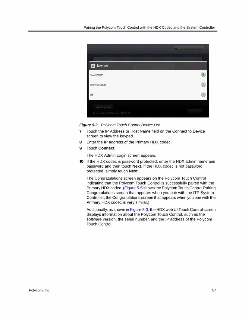
Pairing the Polycom Touch Control with the HDX Codec and the System Controller
Polycom, Inc. 57
Figure 5-2 Polycom Touch Control Device List
7 Touch the IP Address or Host Name field on the Connect to Device screen to view the keypad.
8 Enter the IP address of the Primary HDX codec.
9 Touch Connect.
The HDX Admin Login screen appears.
10 If the HDX codec is password protected, enter the HDX admin name and password and then touch Next. If the HDX codec is not password protected, simply touch Next.
The Congratulations screen appears on the Polycom Touch Control indicating that the Polycom Touch Control is successfully paired with the Primary HDX codec. (Figure 5-5 shows the Polycom Touch Control Pairing Congratulations screen that appears when you pair with the ITP System Controller; the Congratulations screen that appears when you pair with the Primary HDX codec is very similar.)
Additionally, as shown in Figure 5-3, the HDX web UI Touch Control screen displays information about the Polycom Touch Control, such as the software version, the serial number, and the IP address of the Polycom Touch Control.
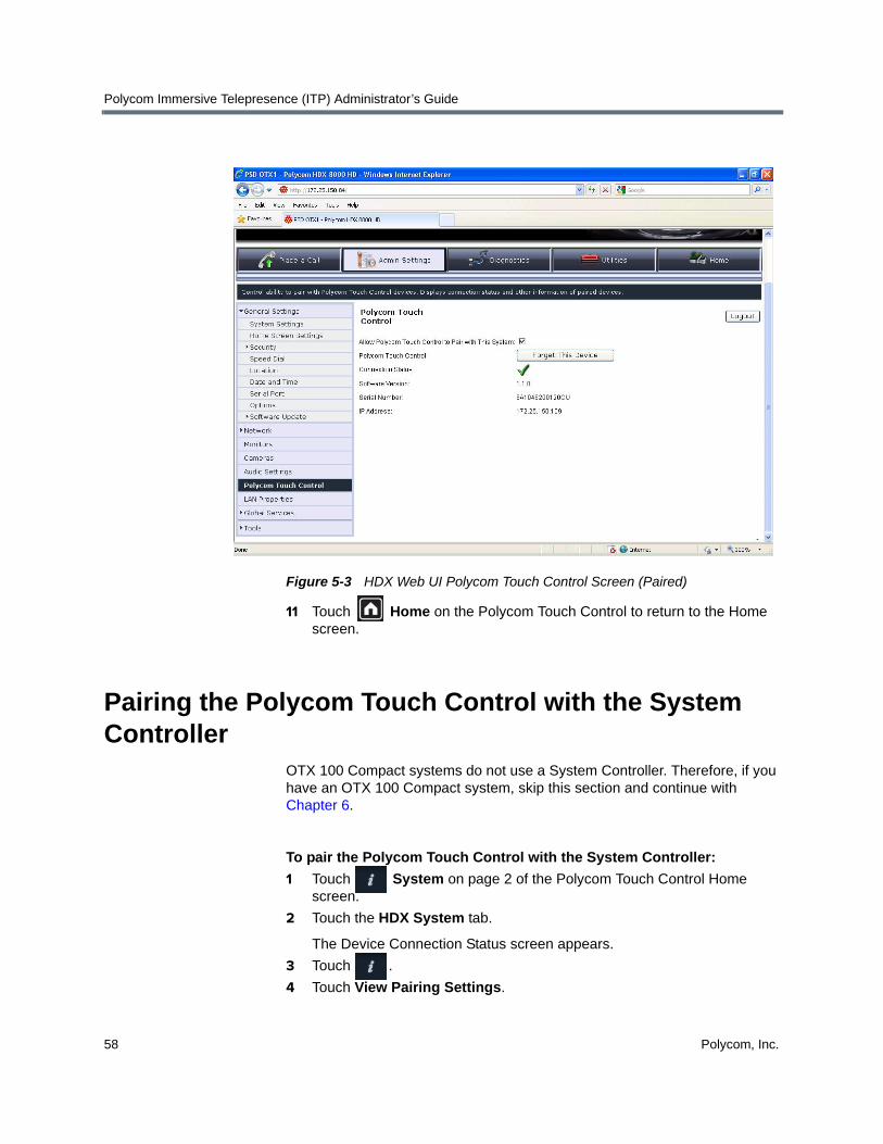
Polycom Immersive Telepresence (ITP) Administrator’s Guide
58 Polycom, Inc.
Figure 5-3 HDX Web UI Polycom Touch Control Screen (Paired)
11 Touch Home on the Polycom Touch Control to return to the Home screen.
Pairing the Polycom Touch Control with the System Controller
OTX 100 Compact systems do not use a System Controller. Therefore, if you have an OTX 100 Compact system, skip this section and continue with Chapter 6.
To pair the Polycom Touch Control with the System Controller:
1 Touch System on page 2 of the Polycom Touch Control Home screen.
2 Touch the HDX System tab.
The Device Connection Status screen appears.
3 Touch .
4 Touch View Pairing Settings.
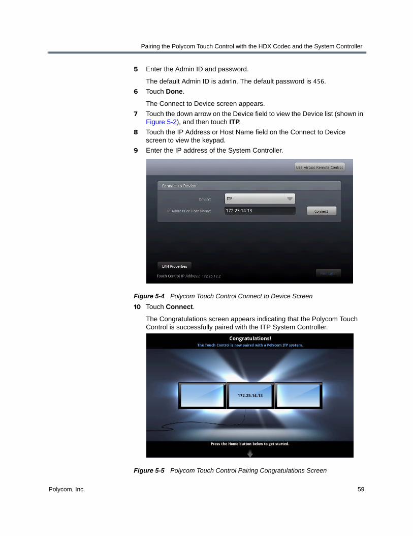
Pairing the Polycom Touch Control with the HDX Codec and the System Controller
Polycom, Inc. 59
5 Enter the Admin ID and password.
The default Admin ID is admin. The default password is 456.
6 Touch Done.
The Connect to Device screen appears.
7 Touch the down arrow on the Device field to view the Device list (shown in Figure 5-2), and then touch ITP.
8 Touch the IP Address or Host Name field on the Connect to Device screen to view the keypad.
9 Enter the IP address of the System Controller.
Figure 5-4 Polycom Touch Control Connect to Device Screen
10 Touch Connect.
The Congratulations screen appears indicating that the Polycom Touch Control is successfully paired with the ITP System Controller.
Figure 5-5 Polycom Touch Control Pairing Congratulations Screen

Polycom Immersive Telepresence (ITP) Administrator’s Guide
60 Polycom, Inc.
11 Touch Home on the Polycom Touch Control to return to the Home screen.
Unpairing the Polycom Touch Control If you ever need to disable the connection between the Polycom Touch Control and the Primary HDX codec and System Controller, you can unpair the Polycom Touch Control using the HDX web interface.
To unpair the Polycom Touch Control:
1 Log into the Polycom HDX web UI.
2 Go to Admin Settings > Polycom Touch Control.
3 Clear the Allow Polycom Touch Control to Pair with this System check box or select Forget this Device.

Polycom, Inc. 61
6Configuring the H.323 Gatekeeper, SIP Server, and Global Directory
This chapter describes how to configure the ITP systems for use with an H.323 gatekeeper, configure the ITP systems for SIP, enable the Telepresence Interoperability Protocol (TIP), and configure the global directory.
If you are using the ITP system with a Microsoft Lync™ Server 2010, refer only to the information in the Configuring ITP Systems for Use with a Lync Server section on page 70. This section provides the instructions you must follow when the ITP system is in a Microsoft environment.
Configuring ITP Systems for Use with an H.323 Gatekeeper
In order to dial other systems by number (instead of by IP address), you must configure the ITP systems to register with an H.323 gatekeeper. For Polycom ITP, the recommended H.323 gatekeeper is the Polycom CMA system. You should register each codec in an ITP room with an H.323 gatekeeper when you first configure each ITP room as well as whenever you add a new room.
• If you register the ITP room with the CMA system, the codecs in that room will be automatically added to the global directory.
Note, however, that even when you register the codecs with the CMA system, those codecs will not be able to access the CMA system directory until you have completed the procedure in the Configuring ITP Systems for Use with the CMA System Directory section on page 66.
• If you do not register the ITP room with a gatekeeper or you register with a gatekeeper other than the CMA system, the codecs in that room will not be automatically added to the global directory.
If you do not use the CMA system as the gatekeeper, but you want to use the CMA system for global directory services, you will need to add all of the codecs manually using the CMA system web UI.
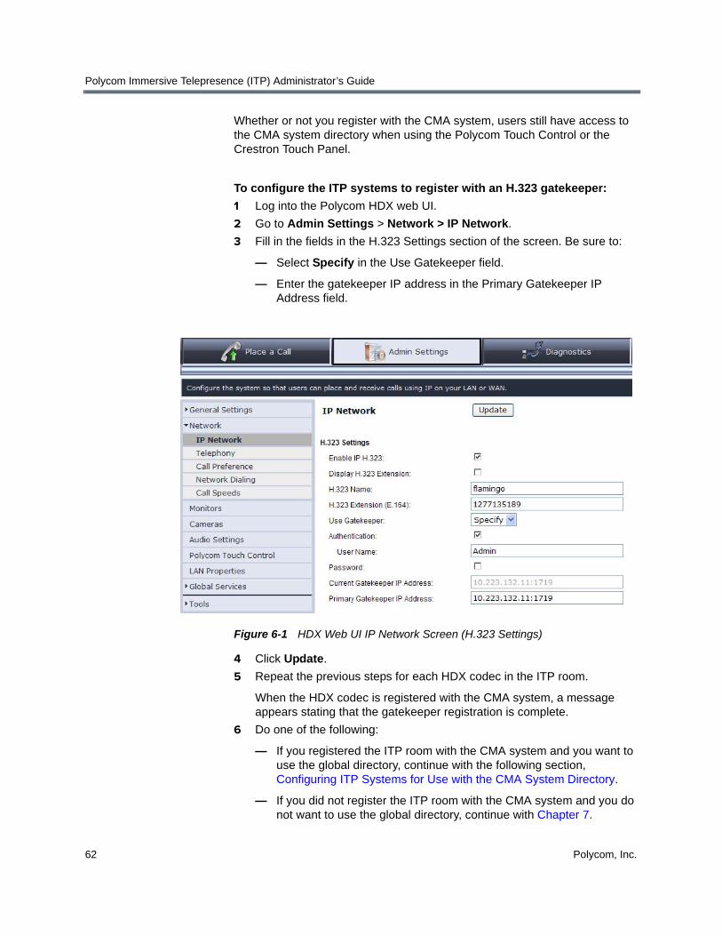
Polycom Immersive Telepresence (ITP) Administrator’s Guide
62 Polycom, Inc.
Whether or not you register with the CMA system, users still have access to the CMA system directory when using the Polycom Touch Control or the Crestron Touch Panel.
To configure the ITP systems to register with an H.323 gatekeeper:
1 Log into the Polycom HDX web UI.
2 Go to Admin Settings > Network > IP Network.
3 Fill in the fields in the H.323 Settings section of the screen. Be sure to:
— Select Specify in the Use Gatekeeper field.
— Enter the gatekeeper IP address in the Primary Gatekeeper IP Address field.
Figure 6-1 HDX Web UI IP Network Screen (H.323 Settings)
4 Click Update.
5 Repeat the previous steps for each HDX codec in the ITP room.
When the HDX codec is registered with the CMA system, a message appears stating that the gatekeeper registration is complete.
6 Do one of the following:
— If you registered the ITP room with the CMA system and you want to use the global directory, continue with the following section, Configuring ITP Systems for Use with the CMA System Directory.
— If you did not register the ITP room with the CMA system and you do not want to use the global directory, continue with Chapter 7.
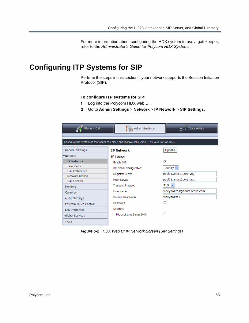
Configuring the H.323 Gatekeeper, SIP Server, and Global Directory
Polycom, Inc. 63
For more information about configuring the HDX system to use a gatekeeper, refer to the Administrator’s Guide for Polycom HDX Systems.
Configuring ITP Systems for SIPPerform the steps in this section if your network supports the Session Initiation Protocol (SIP).
To configure ITP systems for SIP:
1 Log into the Polycom HDX web UI.
2 Go to Admin Settings > Network > IP Network > SIP Settings.
Figure 6-2 HDX Web UI IP Network Screen (SIP Settings)

Polycom Immersive Telepresence (ITP) Administrator’s Guide
64 Polycom, Inc.
3 Fill in the fields in the SIP Settings section of the screen as described in the Administrator’s Guide for Polycom HDX Systems. Be sure to:
— Use the ITP naming convention when entering the User Name on the SIP Settings screen. Refer to With the ITP naming convention, the Primary codec must have a name that indicates that it is an ITP system and how many codecs it has. The corresponding Secondary and any subsequent codecs’ names must be derived from the Primary codec’s name and indicate the codec number.
The examples in the following table show the names you would enter for the Primary, Secondary, and additional codecs if the name of the Primary codec was vineyard.
— Do not select the Microsoft Lync Server 2010 check box.
Enabling the Telepresence Interoperability Protocol (TIP)
ITP systems with software version 3.0.2 or later and the TIP option key can interoperate with TIP endpoints. TIP is a proprietary protocol created by Cisco for deployment with Cisco TelePresence systems (CTS). Polycom ITP solutions now support TIP in order to provide the best possible telepresence experience when interoperating with CTS equipment.
TIP is supported with Polycom ITP systems with Polycom Touch Controls and with the Polycom ATX SDK system. If you are using TIP with one of these systems, follow the steps in this section; otherwise, skip this section and continue with the Enabling User-Initiated Multipoint Conferences section on page 93.
Codec Format Example
Primary codec
<name>itp<number_of_codecs>@<domain>
Secondary codec
~<name>itp<codec_number>@<domain>
Right codec
~<name>itp<codec_number>@<domain>
Leftcodec
~<name>itp<codec_number>@<domain>

Configuring the H.323 Gatekeeper, SIP Server, and Global Directory
Polycom, Inc. 65
To enable TIP:
1 Install the TIP option key on all of the HDX codecs in the ITP system as described in the Upgrading the Polycom HDX Software section on page 1.
When you install the TIP option key, the following changes are made automatically on each of the HDX codecs:
— A TIP check box is displayed and enabled on the HDX Call Preference screen.
— The SIP (TIP) Calls settings appear on the HDX Call Preference screen.
— The 1024 setting is enabled on the HDX Call Speeds screen.
2 Register the Primary HDX codec with the Cisco Unified Communications Manager (CUCM) as described in the Polycom Unified Communications for Cisco Environments document.
3 Verify the settings required for ITP TIP on the HDX Call Preference screen:
a Log into the Polycom HDX web UI.
b Go to Admin Settings > Network > Call Preference.
c Ensure that the H.323, SIP, and TIP check boxes are selected.
Note that if TIP interoperability is required, you must select the SIP and TIP check boxes on all of the codecs in the ITP room. If TIP is not required, do not select the TIP and SIP check boxes.
4 Verify the settings required for ITP TIP on the HDX Network Dialing screen:
a Go to Admin Settings > Network > Network Dialing.
b Ensure that the Preferred Dialing Method field is set to Auto.
c Ensure that the Call Preference field is set to Video then Phone.
Points to note about TIP:
• To use TIP with your ITP system, you must have the Polycom Touch Control. TIP is not supported with Crestron Touch Panels.
• SIP (TIP) calls must connect at a call speed of 1 Mbps or higher.
• Only TIP version 7 is supported.
• In a TIP call, only XGA content at 5 fps is supported. The following content sources are not supported in TIP calls:
— USB content from the Polycom Touch Control
— People+Content IP®

Polycom Immersive Telepresence (ITP) Administrator’s Guide
66 Polycom, Inc.
d If the ITP system needs to be configured to use both TIP and H.323 simultaneously, ensure that the Video Dialing Order #1 field is set to H.323 and the Video Dialing Order #2 field is set to IP SIP.
If the ITP system does not need to be configured to use both TIP and H.323 simultaneously, you can set the Video Dialing Order field as needed for your particular environment.
e Ensure that the Phone Dialing Order field is set to Analog phone.
For more information about configuring settings on the HDX, refer to the Administrator’s Guide for Polycom HDX Systems.
Configuring ITP Systems for Use with the CMA System Directory
To integrate the ITP rooms with the CMA system directory, ensure that you have registered the room with the H.323 gatekeeper as described in the Configuring ITP Systems for Use with an H.323 Gatekeeper section on page 61 or that the CMA system administrator has manually added all of the codecs in the ITP room to the CMA system.
Additionally, you must:
• Configure the ITP rooms to access the CMA system directory server.
• Create ITP rooms and associate endpoints using the CMA system.
• Create groups and associate members using the CMA system.
Configuring the ITP Rooms to Access the CMA System Directory Server
For each ITP room, you must configure the Primary codec to access the CMA system directory server. You do not have to configure the remaining codecs in the room.
To configure the ITP rooms to access the CMA system directory server:
1 Log into the Polycom HDX web UI.
2 Go to Admin Settings > Global Services > Directory Servers.

Configuring the H.323 Gatekeeper, SIP Server, and Global Directory
Polycom, Inc. 67
3 Select the LDAP check box.
Note that GDS is not supported.
Figure 6-3 HDX Web UI LDAP Screen
4 Fill in the remaining fields on the screen:
a The Server Address and Server Port are dependent upon the CMA system IP address and port at the customer site.
b Enter the Group Name of your choice.
c Enter the Base DN (Distinguished Name) as shown in Figure 6-3 unless the CMA system administrator has not used the recommended file system structure. Contact the CMA system administrator if you need more information.
d Enter the Authentication Type, Use SSL (Secure Socket Layer), and Domain Name as shown in Figure 6-3.
e In the User Name field, enter a user name for an account on the CMA system server. The CMA system administrator will provide you with the user name. The user does not have to be an administrator.

Polycom Immersive Telepresence (ITP) Administrator’s Guide
68 Polycom, Inc.
f Select the NTLM Password check box the first time you perform the configuration. You must then enter the password for the CMA system account. The CMA system administrator will provide you with the password.
5 Click Update.
Creating ITP Rooms and Associating Endpoints Using the CMA System
This procedure enables the two, three, or four individual codecs in an ITP room to be associated together as one room. This also enables them to appear as one room in the CMA system directory.
To use the Polycom CMA system to create rooms and associate endpoints, you must be logged in to the CMA system as an administrator. Therefore, you may have to ask the CMA system administrator to perform this procedure for you.
To create ITP rooms and associate endpoints using the CMA system:
1 Log into the Polycom CMA system web UI.
2 Go to Admin > Rooms.
3 On the Rooms page, click Add.
4 Click Manually Define to manually specify the new room details.
5 Complete the General Info section of the Add New Room dialog box as described in the Polycom CMA System Operations Guide.
6 Click Associated Endpoints.
7 Complete the Associated Endpoints section of the Add New Room dialog box:
a Highlight the Primary codec in the Available Endpoints list, and then click the right arrow button to move the codec’s name to the Selected Endpoints list.
Note that the endpoints displayed in the Available Endpoints list include all of the codecs that have been registered with the CMA system. If you do not see the codecs from the ITP room you registered, then you did not register those codecs properly.
b Repeat step 7 a for the Secondary codec and then for the remaining codecs in the room, if any. Be sure to add the codecs in the correct order.
8 Click Ok.
The new room appears in the list.

Configuring the H.323 Gatekeeper, SIP Server, and Global Directory
Polycom, Inc. 69
Creating Groups and Associating Members Using the CMA System
Creating groups in the Polycom CMA system makes it easier for users to find other users in the directory, especially when the directory is large. If you added new ITP rooms (as described in the previous section), you may wish to create new groups for these rooms or you may wish to add the ITP rooms to existing groups.
To use the CMA system to create groups and associate members, you must be logged in to the CMA system as an administrator. Therefore, you may have to ask the CMA administrator to perform this procedure for you.
To create groups and associate members using the CMA system:
1 Log into the Polycom CMA web UI.
2 Go to User > Groups.
3 On the Groups page, click Add Local Group.
4 Complete the General Info section of the Add Local Group dialog box as described in the Polycom CMA System Operations Guide.
Note that, in the Provisioning Profile field, you must leave the default setting as (none). Provisioning is not supported with Polycom ITP.
5 Click Group Members. (No action is required on the Associated Roles tab.)
6 Complete the Group Members section of the Add Local Group dialog box as described in the Polycom CMA System Operations Guide.
7 Click Ok.
The group appears in the Groups list. It is defined as a LOCAL group.
To add members to existing groups using the CMA system:
1 Log into the Polycom CMA web UI.
2 Go to User > Groups.
3 On the Groups page, select the group of interest and click Edit.
4 In the General Info section of the Edit Local Group dialog box, select the Directory Viewable check box if it is not already checked.
5 Click Group Members.
When you add or remove groups in the CMA system, the changes may not be reflected in the HDX web UI for up to one hour. The HDX system queries the CMA system every sixty minutes to refresh the list of groups.
On the Polycom Touch Control or the Crestron Touch Panel, however, the list of groups will be updated whenever the user performs an action that refreshes the screen, such as switching from the Home screen to another screen.
Polycom Immersive Telepresence (ITP) Administrator’s Guide
70 Polycom, Inc.
6 Complete the Group Members section of the Edit Local Group dialog box as described in the Polycom CMA System Operations Guide.
7 Click Ok.
Configuring ITP Systems for Use with a Lync ServerWhen configuring ITP systems for use with a Lync Server 2010, you must:
• Enable HD video on the Lync Server
• Create and enable conference room user accounts
• Hide the Secondary codecs in the Lync directory
• Configure the ITP systems for the Microsoft environment
This section provides an overview of these procedures. You should not attempt to configure your ITP system in a Microsoft environment based solely on the information provided in this section. Rather, you must refer to the Polycom Unified Communications Deployment Guide for Microsoft Environments for detailed information about how to perform each of these tasks.
Enabling HD Video on the Lync Server
If your ITP deployment includes support for higher quality video (RTV), you must change the default video settings of your Lync Server.
For complete information about how to enable HD video on the Lync Server with ITP, refer to the Polycom Unified Communications Deployment Guide for Microsoft Environments available at http://support.polycom.com/PolycomService/support/us/support/strategic_partner_solutions/index.html.
Creating and Enabling Conference Room User Accounts
You must create a conference room user account in Active Directory® for each HDX codec in the ITP room. Once you have added the conference room user accounts to Active Directory, you must enable and configure them for use with the Lync Server. If needed, you should then enable HDX users for remote access and federation.
Keep in mind that, when adding conferencing room user accounts, you must use the ITP naming convention. With the ITP naming convention, the Primary codec must have a name that indicates that it is an ITP system and how many codecs it has. The corresponding Secondary and any subsequent codecs’ names must be derived from the Primary codec’s name and indicate the codec number.
Configuring the H.323 Gatekeeper, SIP Server, and Global Directory
Polycom, Inc. 71
For complete information about how to create and enable conference room user accounts with ITP, refer to the Polycom Unified Communications Deployment Guide for Microsoft Environments available at http://support.polycom.com/PolycomService/support/us/support/strategic_partner_solutions/index.html.
Hiding the Secondary Codecs in the Lync Directory
After you have created and enabled the conference room user accounts for ITP, you should hide the Secondary (and subsequent codecs) in the Lync directory if possible. You can hide the Secondary codecs using either the Exchange Management Console or the ADSI Edit tool on the Lync Server.
For complete information about how to hide Secondary codecs in the Lync directory, refer to the Polycom Unified Communications Deployment Guide for Microsoft Environments available at http://support.polycom.com/PolycomService/support/us/support/strategic_partner_solutions/index.html.
Configuring ITP Systems for the Microsoft Environment
To complete the configuration procedure for ITP systems in a Microsoft environment, you must register each codec in the ITP room with the Lync Server and configure the LAN properties for each codec. You may also have to perform additional configuration procedures. For example, you can configure the Lync Server as your global directory server and you can display your Microsoft contacts in your ITP system contact list.
For complete information about how to configure ITP systems for the Microsoft environment, refer to the Polycom Unified Communications Deployment Guide for Microsoft Environments available at http://support.polycom.com/PolycomService/support/us/support/strategic_partner_solutions/index.html.

Polycom Immersive Telepresence (ITP) Administrator’s Guide
72 Polycom, Inc.

Polycom, Inc. 73
7Managing Favorites and the Local Directory
This chapter describes how to manage Favorites (for ITP sites with a Polycom Touch Control) and how to manage the local directory (for ITP sites with a Crestron Touch Panel supplied by Polycom).
• If the ITP site has a Polycom Touch Control, refer to the following section.
• If the ITP site has a Crestron Touch Panel, refer to the Managing the Local Directory with a Crestron Touch Panel section on page 82.
Managing Favorites with a Polycom Touch ControlIf you have a Polycom Touch Control and you are not using the Polycom CMA system, you must configure Favorites for the ITP rooms so that users can call other rooms without entering the IP address for each room.
If you have a Polycom Touch Control and you are using the Polycom CMA system, you may want to configure Favorites for rooms that are not registered to your CMA server.
You can use the ITP room’s Favorites for any of the following:
• Single endpoints, such as traditional video conferencing systems.
• ITP rooms.
• Multiple endpoints, which consist of more than one traditional video conferencing system and/or ITP room. (A Polycom RMX conference platform is required to speed dial multiple endpoints.)
• Virtual Meeting Rooms (VMRs). (A Polycom RMX conference platform is required to dial VMRs.) For more information about creating VMRs, refer to the Enabling Single Touch Multipoint section on page 102.

Polycom Immersive Telepresence (ITP) Administrator’s Guide
74 Polycom, Inc.
Importing the Speed Dials from the System_Config.ini File
Prior to ITP software version 2.5, video speed dial numbers, audio speed dial numbers, and the Help Desk phone number were configured and stored in the System_Config.ini file. With version 2.5 and later, these numbers are stored in Favorites in the telepresence system’s Primary HDX codec.
For rooms that are upgrading to version 2.5 or later from an earlier version, you can import the speed dial numbers from the System_Config.ini file into the HDX system as described in this section. For new ITP rooms, skip this section and continue with Configuring Favorites on page 75.
To import the speed dials from the System_Config.ini file:
1 Ensure that the Telepresence Tool is launched on the laptop.
2 Click Tools on the Telepresence Tool main screen, and then select Import Speed Dial Numbers.
Alternatively, you can go to All Programs > Polycom > Telepresence Tool > Import Speed Dial Numbers from the Windows Start button.
3 On the Import Speed Dial Numbers dialog box, specify the location of the System_Config.ini file and the IP address of the HDX codec into which the speed dials will be imported.
Follow the steps in this section only if you wish to have the speed dial entries listed as part of the ITP room’s Favorites. If all of the speed dial entries from this ITP system are listed in the CMA directory, you can skip this section and manually create new Favorites from the global directory.
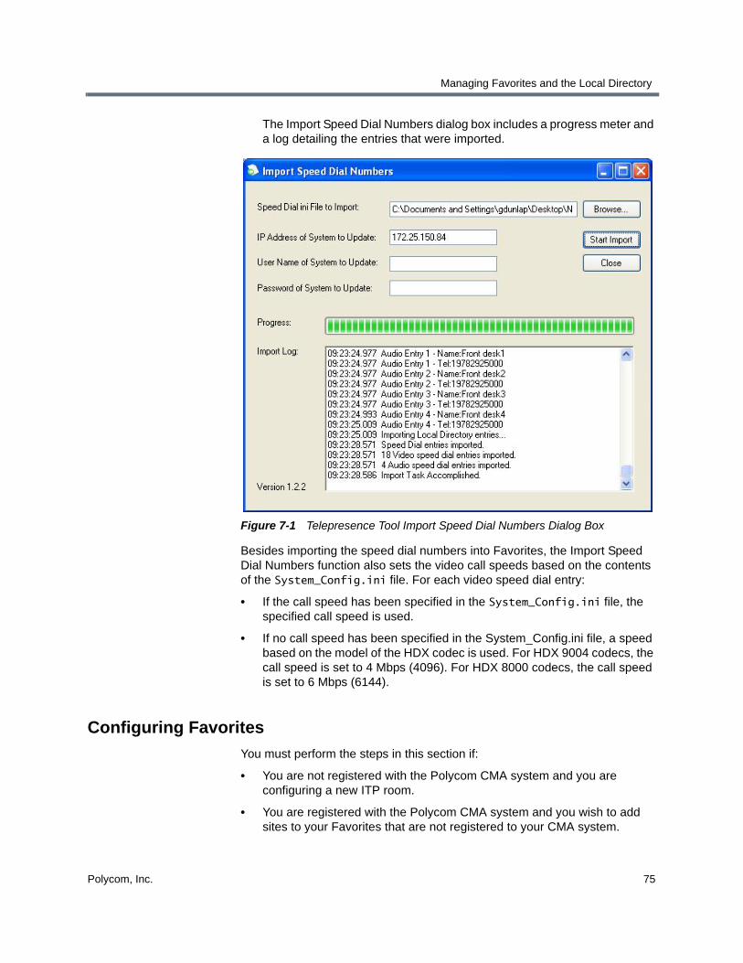
Managing Favorites and the Local Directory
Polycom, Inc. 75
The Import Speed Dial Numbers dialog box includes a progress meter and a log detailing the entries that were imported.
Figure 7-1 Telepresence Tool Import Speed Dial Numbers Dialog Box
Besides importing the speed dial numbers into Favorites, the Import Speed Dial Numbers function also sets the video call speeds based on the contents of the System_Config.ini file. For each video speed dial entry:
• If the call speed has been specified in the System_Config.ini file, the specified call speed is used.
• If no call speed has been specified in the System_Config.ini file, a speed based on the model of the HDX codec is used. For HDX 9004 codecs, the call speed is set to 4 Mbps (4096). For HDX 8000 codecs, the call speed is set to 6 Mbps (6144).
Configuring Favorites
You must perform the steps in this section if:
• You are not registered with the Polycom CMA system and you are configuring a new ITP room.
• You are registered with the Polycom CMA system and you wish to add sites to your Favorites that are not registered to your CMA system.

Polycom Immersive Telepresence (ITP) Administrator’s Guide
76 Polycom, Inc.
• You are not registered with the Polycom CMA system and you are upgrading to ITP version 2.5 or later from an earlier version, and you want to add additional Favorites beyond what you imported from the System_Config.ini file.
• You are registered to a SIP server and you want to add SIP sites to your Favorites. If you are in a Microsoft environment, you can use a Lync client to add Contacts to your account. These Contacts will appear on your Favorites list.
Additionally, you must perform the steps in this section to add the Help Desk number to Favorites.
When configuring Favorites, you can configure both single site entries and multiple site entries.
If another HDX system has many of the Favorites that you need, you can import the Favorites from that HDX system. Refer to the Administrator’s Guide for Polycom HDX Systems for information about how to import and export Favorites. Note that when you import Favorites, there will be no feedback that the import has completed. Rather, you will have to look at the Favorites to see that they have been imported.
The following maximum values are supported when adding new Favorites:
Keep the following restrictions in mind when configuring Favorites:
• ITP versions 2.5 and later do not support ISDN numbers. If there are sites in Favorites that only have ISDN addresses, those sites will not appear on the Polycom Touch Control. Therefore, you should not create Favorites for ISDN-only systems.
• Do not manually create a Favorite that uses the same name as a global directory entry. If you do so, you will have duplicate names in Favorites as well as possible address conflicts. For example, do not add to Favorites a global directory entry named Wintergreen and then manually create a Favorite named Wintergreen.
Favorites Maximum Supported
Number of Favorites 100
Number of groups 10
Number of codecs in a group 24

Managing Favorites and the Local Directory
Polycom, Inc. 77
Configuring the Help Desk Number
To configure the Help Desk number:
1 Log into the Polycom HDX web UI.
2 Go to Admin Settings > General Settings > Location and do the following:
a Ensure that the number entered in the Area Code field is correct.
b Ensure that the Always Dial Area Code check box is selected.
c If the country selected in the Country field is the United States, ensure that the Dial 1+ for all USA Calls check box is selected.
3 Go to Place a Call > Directory.
4 Click Favorites.
5 Click Create Contact.
6 Fill in the following fields on the New Contact screen:
a In the Name field, enter Help Desk.
b In the Call Quality field, leave the default.
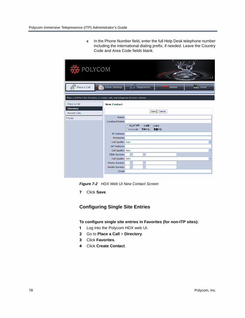
Polycom Immersive Telepresence (ITP) Administrator’s Guide
78 Polycom, Inc.
c In the Phone Number field, enter the full Help Desk telephone number including the international dialing prefix, if needed. Leave the Country Code and Area Code fields blank.
Figure 7-2 HDX Web UI New Contact Screen
7 Click Save.
Configuring Single Site Entries
To configure single site entries in Favorites (for non-ITP sites):
1 Log into the Polycom HDX web UI.
2 Go to Place a Call > Directory.
3 Click Favorites.
4 Click Create Contact.

Managing Favorites and the Local Directory
Polycom, Inc. 79
5 Fill in the fields on the New Contact screen (shown in Figure 7-2):
a In the Name field, enter the name of the site.
If the name consists of fewer than 12 characters, the full name will appear on the Polycom Touch Control UI in all cases. If the name consists of 12 to 24 characters, part of the name may be truncated depending on the width of the letters in the name and if there are spaces in the name.
b In the Call Quality field, set the call speed for the site. You can either select one of the video call speeds from the drop-down list or you can select Auto.
» If you select a call speed, that speed will be used for all calls for this site.
» If you select Auto, the preferred call speed set in the HDX Call Preference screen will be used.
For more information about setting the call speed, see the note on page 47.
c Leave the ISDN Number and ISDN Call Quality fields blank (ITP systems do not support ISDN).
6 Click Save.
For more information about configuring local directory entries on the HDX system, refer to the Administrator’s Guide for Polycom HDX Systems.
To configure single site entries in Favorites (for ITP sites):
1 Log into the Polycom HDX web UI.
2 Go to Place a Call > Directory.
3 Click Favorites.
4 Click Create Contact.
5 Fill in the fields on the New Contact screen (shown in Figure 7-2):
a In the Name field, enter the name.
b Do one of the following:
» Enter the IP address or H.323 extension for each codec in the IP Address field. Delimit each IP address or extension with a semicolon. (Note that, even if you are entering extensions, you must use the IP address field rather than the Extension field.)
The following table provides examples of how to enter the IP addresses or extensions.

Polycom Immersive Telepresence (ITP) Administrator’s Guide
80 Polycom, Inc.
» Enter the SIP address for each codec in the SIP Address field. Delimit each address with a semicolon. Alternatively, if you are using the Microsoft Lync naming convention, specify only the Primary codec (see Configuring ITP Systems for SIP on page 63.)
The following table provides examples of how to enter the SIP addresses.
If you are entering... Follow this format... For example...
IP addresses <IP address for Primary codec>;<IP address2>;<IP address3>;<IP address4>
172.25.100.101;172.25.100.102; 172.25.100.103;172.25.100.104
H.323 extensions
<Extension for Primary codec>;<Extension2>;<Extension3>;<Extension4>
25567;25568;25569;25570
Gatekeeper + H.323 extensions (for point-to- point calls)
<Gatekeeper IP Address> ##<Extension for Primary Codec>;<Gatekeeper>## <Extension2>;<Gatekeeper>## <Extension3>;<Gatekeeper>## <Extension4>
172.25.100.200##25567;
172.25.100.200##25568;
172.25.100.200##25569;
172.25.100.200##25570
Gatekeeper + H.323 extensions (for multipoint calls)
<Gatekeeper IP Address> ##<Extension for Primary Codec>;<Extension2>;<Extension3>;<Extension4>
172.25.100.200##25567;25568;25569;25570
If you are entering... Follow this format... For example...
SIP addresses
<SIP address for Primary codec>@<domain>;<SIP address for Codec2>;<SIP address for Codec3>;<SIP address for Codec4>
[email protected];boston2;boston3;boston4
SIP address in Lync environment
<SIP address for Primary Codec>@<domain>

Managing Favorites and the Local Directory
Polycom, Inc. 81
c In the Call Quality field, set the call speed for the site. You can either select one of the video call speeds from the drop-down list or you can select Auto.
» If you select a call speed, that speed will be used for all calls for this site.
» If you select Auto, the preferred call speed set in the HDX Call Preference screen will be used.
For more information about setting the call speed, see the note on page 47.
d Leave the ISDN Number and ISDN Call Quality fields blank (ITP systems do not support ISDN).
6 Click Save.
The HDX web UI will display all of the ITP room’s codecs. However, on the Polycom Touch Control UI, the room will appear as a single Favorite.
For more information about configuring Favorites on the HDX system, refer to the Administrator’s Guide for Polycom HDX Systems.
Configuring Groups
Keep in mind that although you can configure groups at any site, a Polycom RMX conference platform is required to actually dial the multiple endpoints in a group.
To configure groups in Favorites:
1 Log into the Polycom HDX web UI.
2 Go to Place a Call > Directory.
3 Click Favorites.
4 Click New Group.
5 Enter a group name and click Save.
6 Click Add from Directory.
7 Navigate to the entry that you want to add to the group (for example, if the entry is in the enterprise directory, click Polycom Directory).
8 Click the entry you want to add to the group.
9 Click Add.
Note that the Add button includes the entry name. For example, if the entry name is Andover, the Add button will display Add - Andover).

Polycom Immersive Telepresence (ITP) Administrator’s Guide
82 Polycom, Inc.
10 Repeat steps 6 through 9 for each entry you want to add to the group.
Note that when adding CMA enterprise directory sites to groups, the naming convention is slightly different: the Primary codec will not be numbered and the name will include the suffix HDX. For example, a room with the base name Andover would appear in the enterprise directory as Andover - HDX, Andover - HDX2, Andover - HDX3, and Andover - HDX4.
For more information about configuring Favorites on the HDX system, refer to the Administrator’s Guide for Polycom HDX Systems.
Managing the Local Directory with a Crestron Touch Panel
If you have a Crestron Touch Panel and you are not using the Polycom CMA system, you must configure local directory entries for the ITP rooms so that users can call other rooms without entering the IP address for each room.
If you have a Crestron Touch Panel and you are using the Polycom CMA system, you may want to configure local directory entries for rooms that are not registered to your CMA server.
You can use the ITP room’s local or global directory to configure speed dials for any of the following:
• Single endpoints, such as traditional video conferencing systems.
• ITP rooms.
• Multiple endpoints, which consist of more than one traditional video conferencing system and/or ITP room. (A Polycom RMX conference platform is required to speed dial multiple endpoints.)
• Virtual Meeting Rooms (VMRs). (An Polycom RMX conference platform is required to speed dial VMRs.) For more information about creating VMRs, refer to the Enabling Single Touch Multipoint section on page 102.
Unless you have configured sample sites not to appear in Favorites (as described in step 8 on page 3), sample sites may appear in Favorites on the Polycom Touch Control. If you want to delete these, log into the HDX web UI, select the Sample Sites group, and then delete the sites.

Managing Favorites and the Local Directory
Polycom, Inc. 83
Prior to ITP software version 2.5, the speed dial information was stored in the System_Config.ini file; for version 2.5 and later, it is stored in the telepresence system’s Primary HDX codec.
• If you are upgrading an ITP room to software version 2.5 or later from an earlier version, you can import the speed dials from the System_Config.ini file into the HDX system so that you do not have to manually enter them. For information about how to do this, refer to the following section, Importing the Speed Dials from the System_Config.ini File.
• If you are configuring a new ITP room, continue with Configuring the Local Directory Entries on page 85.
Importing the Speed Dials from the System_Config.ini File
Prior to ITP software version 2.5, video speed dial numbers, audio speed dial numbers, and the Help Desk phone number were configured and stored in the System_Config.ini file. With version 2.5 and later, these numbers are stored in the local directory and speed dial list (also known as the site list) of the telepresence system’s Primary HDX codec.
For rooms that are upgrading to version 2.5 or later from an earlier version, you can import the speed dial numbers from the System_Config.ini file into the HDX system.
To import the speed dials from the System_Config.ini file:
1 Ensure that the Telepresence Tool is launched on the laptop.
2 Click Tools on the Telepresence Tool main screen, and then select Import Speed Dial Numbers.
Alternatively, you can go to All Programs > Polycom > Telepresence Tool > Import Speed Dial Numbers from the Windows Start button.
3 On the Import Speed Dial Numbers dialog box, specify the location of the System_Config.ini file and the IP address of the HDX codec into which the speed dials will be imported.
Follow the steps in this section only if you wish to have the speed dial entries listed as part of the ITP room’s local directory. If all of the speed dial entries from this ITP system are listed in the CMA directory, you can skip this section and manually create new speed dials from the global directory.
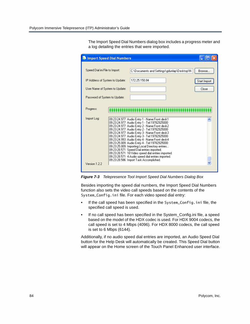
Polycom Immersive Telepresence (ITP) Administrator’s Guide
84 Polycom, Inc.
The Import Speed Dial Numbers dialog box includes a progress meter and a log detailing the entries that were imported.
Figure 7-3 Telepresence Tool Import Speed Dial Numbers Dialog Box
Besides importing the speed dial numbers, the Import Speed Dial Numbers function also sets the video call speeds based on the contents of the System_Config.ini file. For each video speed dial entry:
• If the call speed has been specified in the System_Config.ini file, the specified call speed is used.
• If no call speed has been specified in the System_Config.ini file, a speed based on the model of the HDX codec is used. For HDX 9004 codecs, the call speed is set to 4 Mbps (4096). For HDX 8000 codecs, the call speed is set to 6 Mbps (6144).
Additionally, if no audio speed dial entries are imported, an Audio Speed Dial button for the Help Desk will automatically be created. This Speed Dial button will appear on the Home screen of the Touch Panel Enhanced user interface.
Managing Favorites and the Local Directory
Polycom, Inc. 85
Configuring the Local Directory Entries
You must perform the steps in this section if:
• You are not registered with the Polycom CMA system and you are configuring a new ITP room.
• You are not registered with the Polycom CMA system and you are upgrading to ITP version 2.5 or later from an earlier version, and you want to add additional local directory entries beyond what you imported from the System_Config.ini file.
• You are registered with the Polycom CMA system and you wish to add sites to your local directory that are not registered to your CMA system.
Additionally, you must perform the steps in this section to add the Help Desk number to the local directory.
When configuring the local directory entries, you can configure both single site entries and multiple site entries.
If another HDX system has many of the local directory entries that you need, you can import the local directory from that HDX system. Refer to the Administrator’s Guide for Polycom HDX Systems for information about how to import and export local directories. Note that when you import the local directory, there will be no feedback that the import has completed. Rather, you will have to look at the local directory to see that the entries have been imported.
Keep the following maximum values in mind when adding new directory entries:
Configuring the Help Desk Number
To configure the Help Desk number:
1 Log into the Polycom HDX web UI.
2 Go to Place a Call > Directory.
ITP versions 2.5 and later do not support ISDN numbers. If there are sites in the local or global directory that only have ISDN addresses, those sites will not appear on the Touch Panel. Therefore, you should not create local directory entries or speed dial entries for ISDN-only systems.
Local Directory Maximum Supported
Number of local directory entries 100
Number of groups 10
Number of codecs in a group 24

Polycom Immersive Telepresence (ITP) Administrator’s Guide
86 Polycom, Inc.
3 Click Favorites.
4 Click Create Contact.
5 Fill in the following fields on the New Contact screen (shown in Figure 7-4):
a In the Name field, enter Help Desk.
b In the Call Quality field, leave the default.
c In the Phone Number field, enter the full Help Desk telephone number including the international dialing prefix, if needed. Leave the Country Code and Area Code fields blank.
6 Click Save.
Configuring Single Site Entries
To configure single site entries in the local directory (for non-ITP sites):
1 Log into the Polycom HDX web UI.
2 Go to Place a Call > Directory.
3 Click Favorites.
4 Click Create Contact.
5 Fill in the fields on the New Contact screen:
a In the Name field, enter the name of the site.
If the name consists of fewer than 12 characters, the full name will appear on the Touch Panel UI in all cases. If the name consists of 12 to 24 characters, part of the name may be truncated depending on the width of the letters in the name and if there are spaces in the name.
b In the Call Quality field, set the call speed for the site. You can either select one of the video call speeds from the drop-down list or you can select Auto.
» If you select a call speed, that speed will be used for all calls for this site.
» If you select Auto, the preferred call speed set in the HDX Call Preference screen will be used.
For more information about setting the call speed, see the note on page 47.
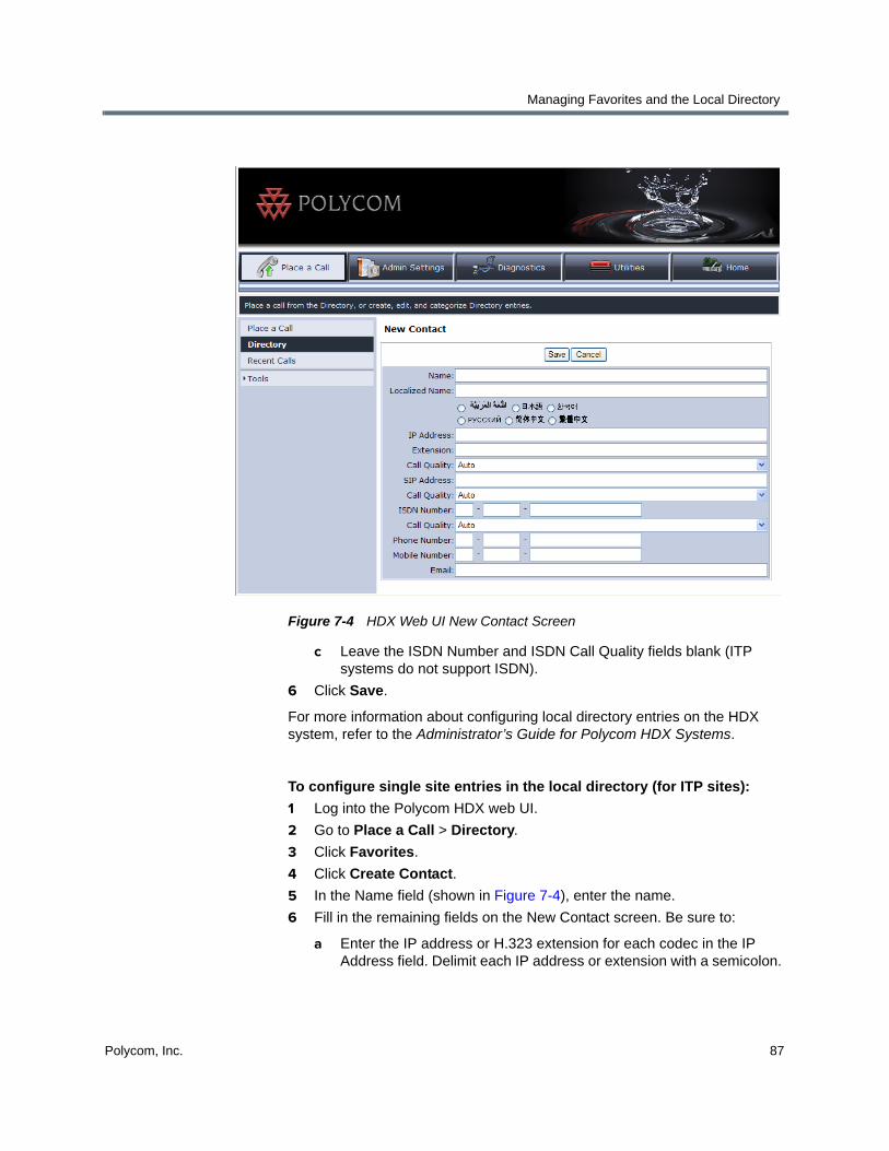
Managing Favorites and the Local Directory
Polycom, Inc. 87
Figure 7-4 HDX Web UI New Contact Screen
c Leave the ISDN Number and ISDN Call Quality fields blank (ITP systems do not support ISDN).
6 Click Save.
For more information about configuring local directory entries on the HDX system, refer to the Administrator’s Guide for Polycom HDX Systems.
To configure single site entries in the local directory (for ITP sites):
1 Log into the Polycom HDX web UI.
2 Go to Place a Call > Directory.
3 Click Favorites.
4 Click Create Contact.
5 In the Name field (shown in Figure 7-4), enter the name.
6 Fill in the remaining fields on the New Contact screen. Be sure to:
a Enter the IP address or H.323 extension for each codec in the IP Address field. Delimit each IP address or extension with a semicolon.

Polycom Immersive Telepresence (ITP) Administrator’s Guide
88 Polycom, Inc.
(Note that, even if you are entering extensions, you must use the IP address field rather than the Extension field.)
The following table provides examples of how to enter the IP addresses or extensions.
b In the Call Quality field, set the call speed for the site. You can either select one of the video call speeds from the drop-down list or you can select Auto.
» If you select a call speed, that speed will be used for all calls for this site.
» If you select Auto, the preferred call speed set in the HDX Call Preference screen will be used.
For more information about setting the call speed, see the note on page 47.
c Leave the ISDN Number and ISDN Call Quality fields blank (ITP systems do not support ISDN).
7 Click Save.
The HDX web UI will display all of the ITP room’s codecs. However, on the Polycom Touch Control UI, the room will appear as a single Favorite.
If you are entering... Follow this format... For example...
IP addresses <IP address for Primary codec>;<IP address2>;<IP address3>;<IP address4>
172.25.100.101;172.25.100.102; 172.25.100.103;172.25.100.104
H.323 extensions
<Extension for Primary codec>;<Extension2>;<Extension3>;<Extension4>
25567;25568;25569;25570
Gatekeeper + H.323 extensions (for point-to- point calls)
<Gatekeeper IP Address> ##<Extension for Primary Codec>;<Gatekeeper>## <Extension2>;<Gatekeeper>## <Extension3>;<Gatekeeper>## <Extension4>
172.25.100.200##25567;
172.25.100.200##25568;
172.25.100.200##25569;
172.25.100.200##25570
Gatekeeper + H.323 extensions (for multipoint calls)
<Gatekeeper IP Address> ##<Extension for Primary Codec>;<Extension2>;<Extension3>;<Extension4>
172.25.100.200##25567;25568;25569;25570

Managing Favorites and the Local Directory
Polycom, Inc. 89
For more information about configuring local directory entries on the HDX system, refer to the Administrator’s Guide for Polycom HDX Systems.
Configuring Groups
Keep in mind that although you can configure groups at any site, a Polycom RMX conference platform is required to actually dial the multiple endpoints in a group.
To configure groups in the local directory:
1 Log into the Polycom HDX web UI.
2 Go to Place a Call > Directory.
3 Click Favorites.
4 Click New Group.
5 Enter a group name and click Save.
6 Click Add from Directory.
7 Navigate to the entry that you want to add to the group (for example, if the entry is in the enterprise directory, click Polycom Directory).
8 Click the entry you want to add to the group.
9 Click Add.
Note that the Add button includes the entry name. For example, if the entry name is Andover1, the Add button will display Add - Andover1).
10 Repeat steps 6 through 9 for each entry you want to add to the group.
When adding an ITP room to a group, you must add all of the room’s codecs. For example, if you are adding an RPX room with the base name Andover, you need to include all four codecs: Andover1, Andover2, Andover3, and Andover4.
Note that when adding enterprise directory sites to groups, the naming convention is slightly different: the Primary codec will not be numbered and the name will include the suffix HDX. For example, a room with the base name Andover would appear in the enterprise directory as Andover - HDX, Andover - HDX2, Andover - HDX3, and Andover - HDX4.
For more information about configuring local directory entries on the HDX system, refer to the Administrator’s Guide for Polycom HDX Systems.
Unless you have configured sample sites not to appear in the local directory (as described in step 8 on page 3), sample sites may appear in the local directory on the Touch Panel. If you want to delete these, log into the HDX web UI, select the Sample Sites group in the local directory, and then delete the sites.

Polycom Immersive Telepresence (ITP) Administrator’s Guide
90 Polycom, Inc.
Configuring Speed Dial Buttons
To provide users with additional convenience, you can configure Speed Dial buttons to correspond to any directory entry (local or global). The Speed Dial buttons appear on the Touch Panel. Therefore, users can simply walk into the ITP room and touch one of the Speed Dial buttons to place the call. Note that speed dials are referred to as sites in HDX versions earlier than version 2.5.
If you are upgrading to ITP version 2.5 or later from an earlier version and you imported the System_Config.ini file, the speed dials from the System_Config.ini file will already be configured.
Keep the following in mind when adding new Speed Dial buttons:
• The maximum number of Speed Dial buttons supported are:
• Up to 9 video Speed Dial buttons and up to 4 audio Speed Dial buttons can appear on the Home screen at one time.
• No single word on a Speed Dial button can be longer than 12 characters.
• The maximum number of characters per Speed Dial button is 24.
• If you have no audio speed dial entries to configure, Polycom highly recommends that you create an Audio Speed Dial button for the Help Desk. This Speed Dial button will appear on the Home Screen of the Touch Panel Enhanced User Interface.
• You can create Speed Dial buttons to call multiple sites at one time. (For more information about user-initiated multipoint conferences, refer to Chapter 8.)
• When you create a new Speed Dial button, you must reboot the System Controller in order for the Speed Dial button to appear on the Touch Panel.
• The order in which the Speed Dial entries appear on the HDX web UI Speed Dial screen is the order in which the Speed Dial buttons will appear on the Touch Panel. For information on how to change the order of the Speed Dial entries on the Speed Dial screen, refer to Changing the Order of Speed Dial Buttons on page 92.
Speed Dials Maximum Supported
Number of video speed dials 18
Number of audio speed dials 4
Do not configure more than 18 video speed dials or 4 audio speed dials. If you do, the video Speed Dial buttons will not display correctly on the Touch Panel and the audio Speed Dial buttons will not display at all.

Managing Favorites and the Local Directory
Polycom, Inc. 91
Adding Speed Dial Buttons
To add Speed Dial buttons:Log into the Polycom HDX web UI.
1 Go to Admin Settings > General Settings > Speed Dial.
2 If needed, click the Speed Dial group.
3 Click Add from Directory.
4 If needed, navigate to the entry that you want to add to the group (for example, if the entry is in the enterprise directory, click Polycom Directory).
5 Click the entry you want to add to the Speed Dial group.
You can select single sites, groups, and Virtual Meeting Room sites.
Figure 7-5 HDX Web UI Speed Dial Screen
6 Click Add.
Note that the Add button includes the entry name. For example, if the entry name is Andover, the Add button will display Add - Andover).

Polycom Immersive Telepresence (ITP) Administrator’s Guide
92 Polycom, Inc.
The entry appears at the bottom of the Speed Dial list on the Speed Dial screen. For information about how to move the entry to another position on the list, refer to the following section, Changing the Order of Speed Dial Buttons.
7 Repeat steps 3 through 6 for each entry you want to add to the Speed Dial group.
If you want to create a Speed Dial button for an ITP room, you must repeat steps 3 through 6 for each codec in the room. The HDX web UI Speed Dial screen will display all of the room’s codecs; however, on the Touch Panel UI, the room will appear as a single entry.
If you add enterprise directory sites to the Speed Dial group, the naming convention is slightly different: the Primary codec will not be numbered and the name will include the suffix HDX. For example, a room with the base name Support would appear in the enterprise directory as Support - HDX, Support - HDX2, Support - HDX3, and Support - HDX4.
Changing the Order of Speed Dial Buttons
The order in which the Speed Dial entries appear on the HDX web UI Speed Dial screen is the order in which the Speed Dial buttons will appear on the Touch Panel. Therefore, you should check that the order of the entries on the Speed Dial screen is correct. For example, for sites with multiple codecs, such as Support - HDX, Support - HDX2, Support - HDX3, and Support - HDX4, it is good practice to keep the codecs together.
To change the order of Speed Dial buttons:Log into the Polycom HDX web UI.
1 Go to Admin Settings > General Settings > Speed Dial.
2 If needed, click the Speed Dial group.
3 Click the entry that you want to move.
4 Click Change Speed Dial Order.
5 Click Move Up to move the entry higher up on the list or click Move Down to move the entry lower down on the list.
6 Repeat steps 3 through 5 for each entry you want to move.
7 When the list is in the order in which you want the Speed Dial buttons to appear on the Touch Panel, click Save Speed Dial Order.

Polycom, Inc. 93
8Managing TIP, User-Initiated Multipoint Conferences, and DBA
This chapter describes how to manage the following in ITP environments:
• User-initiated multipoint conferences including:
— Polycom Conferencing for Microsoft Outlook
— Meeting Composer
— Group Dialing (for Polycom Touch Control sites) or Multipoint Speed Dialing (for Crestron Touch Panel sites)
— Single Touch Multipoint
• Dynamic Bandwidth Allocation (DBA)
Enabling User-Initiated Multipoint ConferencesHistorically, multipoint calls involving ITP systems were initiated by conference operators through the Polycom RMX conference platform. However, with ITP software version 2.5 and later, you can configure your ITP system to enable these four different types of user-initiated multipoint conferences:
• Polycom Conferencing for Microsoft Outlook: Using the Polycom Touch Control or the Crestron Touch Panel, users can view a list of scheduled meetings and join those meetings.
• Meeting Composer: Using the Polycom Touch Control or the Crestron Touch Panel, users can launch multipoint calls directly from the ITP room by choosing all of the conference participants from Favorites (for Polycom Touch Control sites) or from the directory (for both Polycom Touch Control and Crestron Touch Panel sites). Once the conference is connected, users can add and drop conference participants as needed.

Polycom Immersive Telepresence (ITP) Administrator’s Guide
94 Polycom, Inc.
• Group Dialing (for Polycom Touch Control sites) or Multipoint Speed Dialing (for Crestron Touch Panel sites): Using the Polycom Touch Control or the Crestron Touch Panel, users can launch Polycom RMX calls to multiple sites at one time simply by pressing a Favorite (for Polycom Touch Control sites) or a Speed Dial button (for Touch Panel sites) that the administrator has configured to dial a pre-determined list of sites.
• Single Touch Multipoint: Using the Polycom Touch Control or the Crestron Touch Panel, users can call a Polycom RMX Virtual Meeting Room (VMR) simply by pressing a Favorite (for Polycom Touch Control sites) or a Speed Dial button (for Touch Panel sites) that the administrator has configured to dial into the VMR.
These user-initiated multipoint conference features are available only to sites using a Polycom RMX conference platform and the Polycom Multipoint Layout Application (MLA). If the site is using an RMX and the MLA, you should perform the steps in the following subsections whether you are configuring a new ITP room or you are upgrading an ITP room from an earlier version.
Configuring the Polycom MLA, HDX System, and RMX for User-Initiated Multipoint Conferences
To configure user-initiated multipoint conferencing, you must:
• Configure the MLA to run in automatic conference layout mode.
• Set up the proper naming conventions on the HDX codecs.
• Enable specific telepresence conference profiles on a Polycom RMX conference platform.
Configuring the MLA for Automatic Layout Mode
MLA supports two types of automatic conference layout modes:
• Room Continuous Presence: In this standard mode, the multipoint view is automatically generated either to follow the principles of Polycom immersive telepresence multipoint (that is, all participants are “present” during a multipoint conference) or to fit a custom-set view configured by the conference administrator for the sites in a particular conference.
• Voice Activated Room Switching (VARS): VARS is different from standard Room Continuous Presence mode in that the speaker’s site is the only site seen by others. The view of the speaker’s site is sized to be as large as possible on all of the other participants’ displays. The current speaker sees the previous speaker’s site (that is, the speaker’s layout remains unchanged). Layouts used in VARS are not customizable.
If you are using the ATX SDK, some of the functionality described in this chapter may not be available depending on which capabilities your integrator chose to include.

Managing TIP, User-Initiated Multipoint Conferences, and DBA
Polycom, Inc. 95
To enable the MLA to apply these video layouts automatically, you must select the Automatic Layout check box for each Polycom RMX on the MLA MCU Connection screen.
Figure 8-1 MLA MCU Connection Screen
Additionally, you must configure the MLA to connect to each of the RMXs that are used for user-initiated conferences. Typically, this is done by the administrator; therefore, you may have to ask the administrator to perform this procedure for you.
For more information about how to configure the MLA for automatic mode, refer to the Polycom Multipoint Layout Application User Guide.

Polycom Immersive Telepresence (ITP) Administrator’s Guide
96 Polycom, Inc.
Setting Up Naming on the HDX Codecs
An ITP room system contains multiple endpoints (codecs). Polycom MLA and Polycom DMA use the following naming convention for the HDX codecs to determine that the endpoints are part of the same ITP room.
The system administrator must set the same name for both the HDX system name and H.323 name for each HDX in the system using the following naming convention:
<system_name>_M_N
• “<system_name>” is any valid H.323 alias string.
• “M” is the total number of HDXs in the system.
• “N” is the individual unit number.
For example, the three HDX devices in an OTX 300 system for New Company in New Jersey could register with the following system and H.323 names:
• NewCo NJ_3_1
• NewCo NJ_3_2
• NewCo NJ_3_3
The following table lists the individual unit number “N” numbering convention for the codecs in RPX, OTX, TPX, and ATX rooms:
If non-ITP participants in a conference have names that differ only by the final digit, MLA could accidentally treat those sites as parts of an ITP room, resulting in incorrect video layouts in the conference.
Telepresence System Left Center Right
RPX 200/ATX 200TPX 204M
2 1
RPX 400/ATX 400 4 Left: 2, Right: 1
3
OTX 300TPX 306MATX 300CTS 3000
2 1 3
OTX 100TPX 100CTS 1000Standalone
1

Managing TIP, User-Initiated Multipoint Conferences, and DBA
Polycom, Inc. 97
The following figure shows an example of the naming conventions used for four different sites: Acme Corporation in New York, which has an RPX 200 Series; Polycom in Boston, which has an RPX 400 Series; New Company in New Jersey, which has an OTX 300, and Polycom in Austin, which has an OTX 100:
Follow this naming convention for the H.323 Name field on the IP Network page and for the System Name field on the System Settings page of the HDX web UI or the HDX embedded UI. For more information, see the following documents:
• Administrator’s Guide for Polycom HDX Systems
• Polycom DMA 7000 System Operations Guide
• Polycom Immersive Telepresence (ITP) Deployment Guide
• Polycom Multipoint Layout Application (MLA) User’s Guide for Use with Polycom Telepresence Solutions
When naming the sites, keep the following in mind:
• The codec associated with the camera that shows the right side of the room from the camera point of view is the same codec that drives the right display from the point of view of the participants seated at the table.
• Codec 1 in all telepresence rooms is the primary codec. The primary codec is the codec through which the audio and content video are sent and received. The remaining (non-primary) codecs handle people video only.
RPX 200ATX 200TPX 204M
Acme NY_2_2 Acme NY_2_1
PolycomBoston_4_4
PolycomBoston_4_2
PolycomBoston_4_1
PolycomBoston_4_3
NewCo NJ_3_2 NewCo NJ_3_1 NewCo NJ_3_3
OTX 300TPX 306MATX 300CTS 3000
RPX 400ATX 400
PolycomAustin_1_1
OTX 100TPX 100CTS 1000Standalone

Polycom Immersive Telepresence (ITP) Administrator’s Guide
98 Polycom, Inc.
Configuring the Polycom RMX Conference Profile
To use the user-initiated multipoint conferencing features, you must configure a conference profile on each of the Polycom RMX conference platforms that are used for user-initiated conferences. Typically, this is done by the administrator; therefore, you may have to ask the administrator to perform this procedure for you.
For complete information about supported conference profiles for telepresence, refer to the Polycom Immersive Telepresence Deployment Guide. For complete information about configuring the Polycom RMX, refer to the RMX Administrator’s Guide.
When configuring the Polycom RMX, note that MPM, MPM+, and MPMx hardware support telepresence conference profiles.
Enabling Polycom Conferencing for Microsoft Outlook
Polycom Conferencing for Microsoft Outlook enables ITP system users to use the calendar feature on the Polycom Touch Control or on the Crestron Touch Panel. This feature is available only:
• If the ITP system can connect to the Microsoft Exchange Server 2007.
• If the Enhanced UI is being used (for Touch Panel sites only).
To enable Polycom Conferencing for Microsoft Outlook:
1 Configure the mailboxes and Active Directory accounts for each ITP room.
You must configure an Exchange room mailbox and an Active Directory account (which is used to authenticate with Exchange) for each ITP room. Note that you must configure the mailbox and account for each ITP room, not for each HDX codec in the ITP room.
Polycom Implementation and Maintenance services provide support for Polycom solution components only. Additional services for supported third-party Unified Communications (UC) environments integrated with Polycom solutions are available from Polycom Global Services and its certified Partners to help customers successfully design, deploy, optimize, and manage Polycom visual communication within their third-party UC environments. UC Professional Services for Microsoft Integration is mandatory for Polycom Conferencing for Microsoft Outlook and Microsoft Office Communications Server or Microsoft Lync Server integrations. For additional information and details, please refer to http://www.polycom.com/services/professional_services/index.html or contact your local Polycom representative
Managing TIP, User-Initiated Multipoint Conferences, and DBA
Polycom, Inc. 99
Keep in mind that, in many environments, User and Room accounts are likely to already be configured. However, room mailboxes and accounts associated with the ITP room need additional configuration.
For more information about how to perform this step, refer to the “Configure Mailboxes for Room-based HDX Systems” section of the Polycom Unified Communications Deployment Guide for Microsoft Environments. This guide is available at http://support.polycom.com/PolycomService/support/us/support/strategic_partner_solutions/microsoft_software_download.html.
2 Configure Polycom HDX system calendaring settings.
You must configure calendaring settings for the Primary HDX codec in the ITP room. When configuring these settings for the Primary HDX codec, you need to specify the Room Mailbox and the Active Directory user name for the service account that manages the mailbox.
For more information about how to perform this step, refer to the “Configure Polycom HDX System Calendaring Settings” section in the Polycom Unified Communications Deployment Guide for Microsoft Environments. This guide is available at http://support.polycom.com/PolycomService/support/us/support/strategic_partner_solutions/microsoft_software_download.html. You can also refer to the Administrator’s Guide for Polycom HDX Systems for additional information about configuring HDX settings.
If the ITP system is not registered with calendaring services and you choose to register it by selecting the Register with Calendaring Services check box on the HDX web UI Calendaring Service screen, you must reboot the System Controller in order to enable the calendar features on the Polycom Touch Control or on the Crestron Touch Panel.
Polycom Immersive Telepresence (ITP) Administrator’s Guide
100 Polycom, Inc.
Enabling Meeting Composer and Group Dialing or Multipoint Speed Dialing
In order to enable Meeting Composer and either group dialing (for ITP sites with a Polycom Touch Control) or Multipoint Speed Dial (for ITP sites with a Crestron Touch Panel):
• Ensure that you have set up the MLA for automatic layout mode.
• Ensure that you have set up the proper naming conventions on the HDX codecs.
• Ensure that you have configured the Polycom RMX conference profile.
• Configure the ITP room’s Primary HDX codec to access the Polycom RMX as described in the following section. If not, the Polycom Touch Control or Crestron Touch Panel UI will not allow the user to enter more than one site into a call.
• For sites using the Crestron Touch Panel only, ensure that the Touch Panel is configured to use the Enhanced UI as described in the Selecting the Enhanced or the Classic User Interface on page 26.
Note that the Enhanced UI is only available for ITP systems using the 10-inch Touch Panel.
Configuring the ITP Room to Access the Polycom RMX
For each ITP room, you must configure the Primary HDX codec in the room to access the Polycom RMX. You do not have to configure the remaining codecs in the room.
To configure the ITP room to access the Polycom RMX:
1 Log into the Polycom HDX web UI.
2 Go to Admin Settings > Global Services > Conference Server.
Note that the Conference Server menu item only appears if the HDX is configured as a telepresence system.
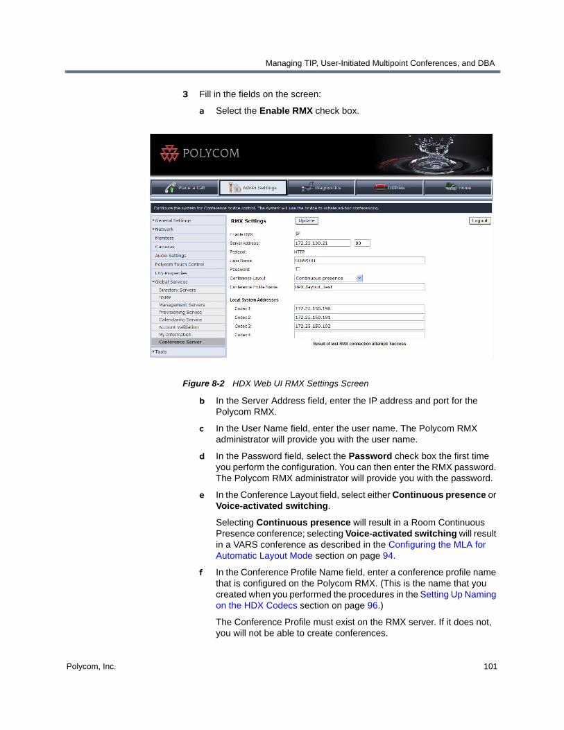
Managing TIP, User-Initiated Multipoint Conferences, and DBA
Polycom, Inc. 101
3 Fill in the fields on the screen:
a Select the Enable RMX check box.
Figure 8-2 HDX Web UI RMX Settings Screen
b In the Server Address field, enter the IP address and port for the Polycom RMX.
c In the User Name field, enter the user name. The Polycom RMX administrator will provide you with the user name.
d In the Password field, select the Password check box the first time you perform the configuration. You can then enter the RMX password. The Polycom RMX administrator will provide you with the password.
e In the Conference Layout field, select either Continuous presence or Voice-activated switching.
Selecting Continuous presence will result in a Room Continuous Presence conference; selecting Voice-activated switching will result in a VARS conference as described in the Configuring the MLA for Automatic Layout Mode section on page 94.
f In the Conference Profile Name field, enter a conference profile name that is configured on the Polycom RMX. (This is the name that you created when you performed the procedures in the Setting Up Naming on the HDX Codecs section on page 96.)
The Conference Profile must exist on the RMX server. If it does not, you will not be able to create conferences.

Polycom Immersive Telepresence (ITP) Administrator’s Guide
102 Polycom, Inc.
g In the Local System Addresses fields, enter the addresses of the local ITP room’s codecs (the Polycom RMX will use these addresses to call the room). You can enter IP addresses, H.323 E.164 numeric addresses, H.323 alphanumeric aliases, or SIP addresses in these fields.
If your system is configured for both SIP and H.323, include the protocol prefix in the address, such as h323:22345 or sip:[email protected].
4 Click Update.
5 Reboot the System Controller.
(Anytime you enable or disable the Polycom RMX, you must reboot the System Controller to make it aware of the change.)
Enabling Single Touch Multipoint
To enable Single Touch Multipoint, you must:
1 Create a Virtual Meeting Room on the Polycom RMX.
2 Add the Virtual Meeting Room to Favorites (for ITP sites with a Polycom Touch Control) or to the local directory (for ITP sites with a Crestron Touch Panel).
3 Configure the speed dials for the Virtual Meeting Rooms (for ITP sites with a Crestron Touch Panel only).
Each of these is explained in the following sections.
Creating a Virtual Meeting Room on the Polycom RMX
When creating the VMR for Single Touch Multipoint, keep the following general guidelines in mind:
• You can configure any number of VMRs on the RMX with a conference profile that has telepresence mode enabled. Each VMR must have a dial-in number.
• To indicate to the MLA that the conference should be given an automatic video layout, configure the settings for Telepresence in the RMX conference profile. For information about how to do this, refer to the RMX Administrator’s Guide and the Polycom Immersive Telepresence Deployment Guide.
Note that in RMX Version 5.0 and earlier, a naming convention using the keywords AUTO and ROOMSWITCH was used. In most cases, this convention is no longer required. If, however, this older convention is used, the MLA will follow it instead of the current settings.
• Optionally, the VMR can require a password for access. Configure the password for a Single Touch Multipoint conference in the same way as any RMX password-protected conference.

Managing TIP, User-Initiated Multipoint Conferences, and DBA
Polycom, Inc. 103
• To enable the Polycom RMX to automatically connect to a particular site when another site dials in to a VMR, you can add that particular site as a dial-out participant in the VMR. For example, if you always want the RMX to connect to Site ABC when Site XYZ dials in, you can add Site ABC as a dial-out participant in the VMR.
When you are creating the VMR, be sure to note down the following:
• The RMX prefix.
• The meeting room ID.
When combined, these two become the VMR address. For example, if the RMX prefix is 12 and the meeting room ID is 4000, the VMR address is 124000.
Adding a Virtual Meeting Room to Favorites (Sites with a Polycom Touch Control)
At ITP sites with a Polycom Touch Control, adding a Virtual Meeting Room (VMR) to Favorites is similar to adding an ITP room. When dialing into a VMR, each of the local ITP system’s codecs calls the same VMR address; therefore, you must add a site to Favorites that has the same number of codecs as the local system, with each codec having the same address.
For example, if the VMR is named Evergreen, the VMR address is 138888, and the local system has four codecs, you must perform steps 1 through 6 on page 79 and 81 to create one Favorite named Evergreen that has the same address for each codec, such as 13888;13888;13888;13888.
Adding a Virtual Meeting Room to the Local Directory (Sites with a Crestron Touch Panel)
At ITP sites with a Crestron Touch Panel supplied by Polycom, adding a Virtual Meeting Room (VMR) to the local directory is similar to adding an ITP room. When dialing into a VMR, each of the local ITP system’s codecs calls the same VMR address; therefore, you must add a site to the directory that has the same number of codecs as the local system, with each codec having the same address.
For example, if the VMR is named Evergreen, the VMR address is 138888, and the local system has four codecs, you must perform steps 1 through 6 on page 79 and 81 to create one Favorite named Evergreen that has the same address for each codec, such as 13888;13888;13888;13888.

Polycom Immersive Telepresence (ITP) Administrator’s Guide
104 Polycom, Inc.
Configuring the Favorites or the Speed Dials for Virtual Meeting Rooms (Sites with a Crestron Touch Panel)
At ITP sites with Crestron Touch Panel supplied by Polycom, once you have added the VMRs to the local directory, you can create Speed Dial buttons for the VMRs. You can do this in the same way you create other Speed Dial buttons. For information about how to do this, refer to Configuring Speed Dial Buttons on page 90.
TPX Limitation (Sites with a Crestron Touch Panel)
If a TPX HD 204M calls into an Polycom RMX VMR, it will appear to the MLA as if it were an RPX HD 200 Series room. The default automatic layouts for Room Continuous Presence conferences that include any anonymous dial-in TPX HD 204M systems will not work well.
To correct this, you can configure the RMX meeting room to have a known dial-in entry from the RMX address book. If the TPX HD 204M room is pre-configured as a dial-in entry, then it will be recognized properly as a TPX HD 204M by the MLA.
Disabling Dynamic Bandwidth Allocation (DBA)Polycom recommends that you disable Dynamic Bandwidth Allocation (DBA) for ITP systems.
ITP systems are commonly deployed in environments that have a network designed and managed to always provide bandwidth without congestion, therefore DBA is not required.
To disable DBA:
1 Log into the Polycom HDX web UI.
2 Go to Admin Settings > Network > IP Network.
3 In the Quality of Service section, clear the Dynamic Bandwidth check box.
For more information about DBA and the Quality of Service settings, refer to the Administrator’s Guide for Polycom HDX Systems.
If your ITP network environment does not always provide bandwidth without congestion, then DBA can be enabled to help improve the overall quality of the conferencing link.

Polycom, Inc. 105
9Maintaining the ITP Room
This chapter lists procedures you may need to perform to maintain the RPX, OTX, TPX, or ATX telepresence rooms. These procedures include:
• Powering up and down
• Configuring the NTSC and PAL camera settings
• Accessing the RPX security camera
• Accessing the HDX, RMX, and Polycom Touch Control logs
• Checking the OTX and TPX display settings
• Using the Admin screen
• Using Telnet commands to access the System Controller
• Replacing the RPX and OTX lamps and bulbs
• Caring for the room
Powering Up and DownThis section describes how to power up and power down all of the components in the ITP room whether you are physically located in the room or you are at a remote site.
Powering Up and Down While Onsite
To power up while onsite:
1 Power up all of the components in the room (except for the System Controller) by plugging in the components and/or pressing the Power buttons on the components.
2 Wait until all of the HDX codecs are completely powered up, and then power up the System Controller.

Polycom Immersive Telepresence (ITP) Administrator’s Guide
106 Polycom, Inc.
To power down while onsite:
1 For RPX sites only, power down the projectors using the Display Off button on the Admin screen. Wait five minutes to allow the projectors to cool down.
For more information about the Admin screen, see the Accessing and Using the Admin Screen section on page 121.
2 Power down the remaining components in the room either by pressing the Power buttons or by unplugging the components.
Powering Up and Down Remotely (RPX and OTX Sites)
You can remotely power up and power down all of the components that are connected to the APC® Power Distribution Unit (PDU) at RPX and OTX sites. For both RPX and OTX systems, the APC PDU provides power to components such as the HDX codecs and the System Controller.
In order to power up and down remotely, all cables to the PDU must be connected according to the wiring specification:
• For RPX HD 400 Series systems, refer to the Polycom RPX HD 400 System Design Specification (part number 3725-09582-001 for North America or 3725-09583-001 for elsewhere).
• For RPX HD 200 Series systems, refer to the Polycom RPX HD 200 System Design Specification (part number 3725-09584-001 for North America or 3725-09585-001 for elsewhere).
• For OTX 300 systems, refer to the Open Telepresence Experience (OTX) 300 System Wiring Specification (part number 3725-09744-001).
• For OTX 100 systems, refer to the Open Telepresence Experience (OTX) 100 System Wiring Specification (part number 3725-63288-001 for standard OTX 100 systems or part number 3725-63544-001 for OTX 100 Compact systems).
To power up remotely:
1 Connect to the APC power switch in the telepresence room by entering the IP address of the APC.
Each of the components connected to the ports on the APC will appear onscreen.
2 Select the components you want to power up except for the System Controller.
3 Wait until all of the HDX codecs are completely powered up, and then power up the System Controller.

Maintaining the ITP Room
Polycom, Inc. 107
To power down remotely:
1 For RPX sites only, access the System Controller via a Telnet connection, and issue the display off command to power down the projectors. Wait five minutes to allow the projectors to cool down.
For more information about using Telnet commands, see the Using Telnet Commands to Access the System Controller section on page 126.
2 Connect to the APC power switch in the telepresence room by entering the IP address of the APC.
Each of the components connected to the ports on the APC will appear onscreen.
3 Select the components you want to power down.
Configuring the NTSC and PAL Camera Settings (RPX and OTX Sites)
RPX system cameras are automatically set to NTSC (60 Hz) when the Polycom installer runs the Telepresence Tool during the installation procedure. Do not change this setting regardless of the country in which the RPX system is located.
OTX system cameras may be set to NTSC or PAL depending on the lights in the room and the country in which the room is located.
Accessing the Security Camera (RPX Sites)The security camera is also known as the web camera or the rear monitoring camera, and is available only at RPX sites. You can monitor the RPX room using this camera. This is often helpful when a customer in the RPX room calls for technical assistance.
Depending on when the RPX system was installed, the security camera may be the Axis® camera part number 1624-63854-001 or part number 1624-28763-001:
• If you need additional information about Axis camera (part number 1624-63854-001), refer to the Axis M31 Network Camera Series Installation Guide or User’s Manual.
• If you need additional information about Axis camera (part number 1624-28763-001), refer to the Axis 209MFD/MFD-R/MFD-R M12 Fixed Dome Network Camera Installation Guide or User’s Manual.

Polycom Immersive Telepresence (ITP) Administrator’s Guide
108 Polycom, Inc.
The Axis installation instructions are included with the security camera kit, and the user guide is available on the CD that is provided with the camera. You can also find these documents online at http://www.axis.com/techsup/.
Before you access the security camera, you must ensure that:
• You are using one of these supported web browsers: Microsoft Internet Explorer®, Mozilla® Firefox®, or Apple® Safari®.
• You have the IP address for the camera.
The IP address is typically assigned by the installer during the RPX system installation. However, if you need information about how to assign the IP address, refer to the Axis Installation Guide or User’s Manual.
• You have the root password for the camera.
The root password is typically set by the installer during the RPX system installation. However, if you need information about how to set the password, refer to the Axis Installation Guide or User’s Manual.
To access the security camera:
1 Start your Microsoft Internet Explorer, Mozilla Firefox, or Apple Safari browser.
2 Enter the IP address or host name of the camera in the Location/Address field of your browser.
If you have a Macintosh computer, click the Bonjour tab and select AXIS M3113\ASIX M3114 from the drop-down list.
3 Enter the user name and password.
The camera’s Live View page appears in your browser. You can then pan and zoom to view the room, take snapshots to document a problem, or perform any of the other functions described in the Axis User’s Manual.

Maintaining the ITP Room
Polycom, Inc. 109
Accessing the HDX, RMX, and Polycom Touch Control Logs
This section describes how to access the HDX, RMX, and Polycom Touch Control logs. If a problem occurs, you may be asked to access the logs so that you can send them to your support representative. For the Polycom Touch Control, you may want to transfer the logs to a USB storage device before the log threshold is reached.
Accessing the HDX Logs
To access the HDX logs:
1 Log into the Polycom HDX web UI.
2 Go to Diagnostics > System Log > Download Logs.
3 Click Download support information package...
4 Select Save and select the directory where you want to save the log files.
Accessing the RMX Logs
Only users who are logged in as administrators are allowed access to the RMX logs.
To access the RMX logs:
1 Log into the Polycom RMX web UI as an administrator.
2 Go to Administration > Tools > Logger Diagnostics Files.
3 On the Logger Diagnostics File screen, highlight the logs that you want.
You can use the date and time stamp to quickly find the needed logs.
4 Click Browse to select the directory where you want to save the log files.
5 Click Retrieve Files.
Polycom Immersive Telepresence (ITP) Administrator’s Guide
110 Polycom, Inc.
Accessing the Polycom Touch Control Logs
You can transfer the Polycom Touch Control logs to an external USB storage device.
To access the Polycom Touch Control logs:
1 Ensure that a USB device is connected to the USB port on the right side
of the Polycom Touch Control.
2 Touch Administration on page 3 of the Polycom Touch Control
Home screen.
3 Enter the Admin ID and password.
The default Admin ID is admin. The default password is 456.
4 Under Security, select Transfer Touch Control Logs to USB Device.
A pop-up message displays when the log transfer completes successfully.
Checking the Display Settings (OTX and TPX Sites)This section lists the display settings for the OTX 300, OTX 100, and TPX HD 306M displays. The settings may vary depending on your display model as well as your software version. These settings should not be changed after the initial installation. However, if a user inadvertently changes some of the settings, you may need to check and reset them.
To perform this procedure, you must:
• Be on site in the OTX or TPX room.
• Have access to the display remote controls.
• Ensure that each display is powered on.

Maintaining the ITP Room
Polycom, Inc. 111
OTX Display Settings
To check the display settings at OTX sites:
>> For all OTX displays, these are the settings:
Menu Setting
Picture Picture Mode = Polycom
Contrast = N/A
Brightness = N/A
Color = N/A
Sharpness = N/A
Tint = N/A
3d NR = N/A
MPEG NR = N/A
= 16:9
Picture (continued) Color Temp = N/A
Setup Menu Language = English
Menu Timeout = 10s
Menu Background = Opaque
Sleep Timer = OFF
Backlight = LIGHT
Power Save = 1 Min
Auto Power Down = OFF
Memo = OFF
Status Display = OFF
S/W Version = 65FADM-100629
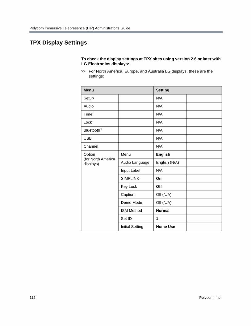
Polycom Immersive Telepresence (ITP) Administrator’s Guide
112 Polycom, Inc.
TPX Display Settings
To check the display settings at TPX sites using version 2.6 or later with LG Electronics displays:
>> For North America, Europe, and Australia LG displays, these are the settings:
Menu Setting
Setup N/A
Audio N/A
Time N/A
Lock N/A
Bluetooth® N/A
USB N/A
Channel N/A
Option (for North America displays)
Menu English
Audio Language English (N/A)
Input Label N/A
SIMPLINK On
Key Lock Off
Caption Off (N/A)
Demo Mode Off (N/A)
ISM Method Normal
Set ID 1
Initial Setting Home Use

Maintaining the ITP Room
Polycom, Inc. 113
Option (for Europe displays)
Menu English
Audio Language English
Subtitle Language
English
Hard of Hearing Off
Country UK
Input Label N/A
SIMPLINK On
Key Lock Off
Simple Manual N/A
Set ID 1
ISM Method Normal
Mode Setting Home Use
Factory Reset N/A
Option (for Australia displays)
Subtitle Off (N/A)
Input Label N/A
SIMPLINK On
Key Lock Off
Set ID 1
ISM Method Normal
Option (for Australia displays)
Demo Mode Off
Mode Setting Home Use
Factory Reset N/A
Menu Setting

Polycom Immersive Telepresence (ITP) Administrator’s Guide
114 Polycom, Inc.
Picture Aspect Ratio Just Scan
Picture Wizard N/A
Energy Saving Off
Picture Mode Standard (User)
Contrast = 90
Brightness = 50
Sharpness = 40
Colour = 60
Tint = 0
Advanced Control
Colour Temperature = Medium
Dynamic Contrast = Off
Dynamic Colour = Off
Noise Reduction = Low
Gamma = Medium
Black Level = Low
Film Mode = Off (N/A)
Colour Gamut = Wide
Edge Enhancer = On
xvYCC = N/A
Menu Setting

Maintaining the ITP Room
Polycom, Inc. 115
To check the display settings at TPX sites using version 2.0 or later with Pioneer® displays:
• For North America Pioneer displays (model number PDP-6020FD), these are the settings:
Menu Setting
Channel N/A
Favorite N/A
Input Input 4
Home Media Gallery N/A
Setup Option HDMI Input Signal Type = Video
Video = Color-3
Audio = AUTO
HDMI Control Settings
Input Setting = Off
Orbiter = Off
Label Input = N/A
Auto Size = Off
Side Mask Brightness Sync = Fixed
Video Pattern = N/A
Game Control Pref = Off
Room Light Sensor = Off
Screen Protection = No
Label Input = N/A
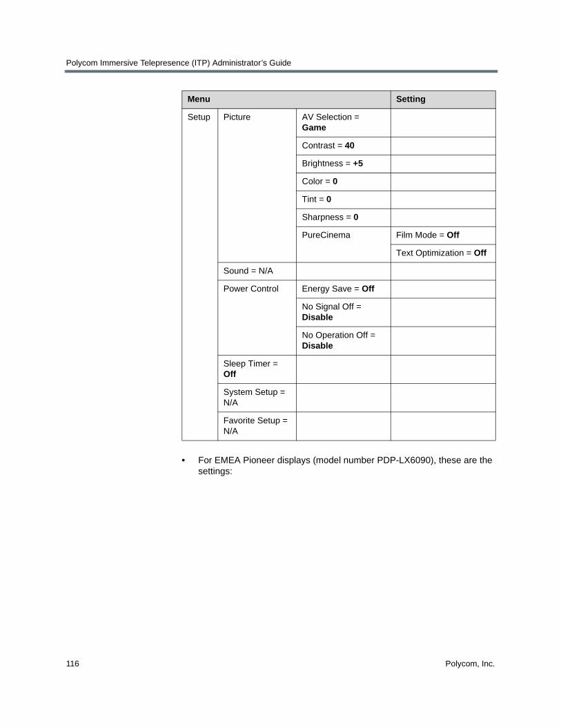
Polycom Immersive Telepresence (ITP) Administrator’s Guide
116 Polycom, Inc.
• For EMEA Pioneer displays (model number PDP-LX6090), these are the settings:
Setup Picture AV Selection = Game
Contrast = 40
Brightness = +5
Color = 0
Tint = 0
Sharpness = 0
PureCinema Film Mode = Off
Text Optimization = Off
Sound = N/A
Power Control Energy Save = Off
No Signal Off = Disable
No Operation Off = Disable
Sleep Timer = Off
System Setup = N/A
Favorite Setup = N/A
Menu Setting
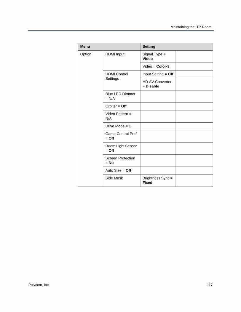
Maintaining the ITP Room
Polycom, Inc. 117
Menu Setting
Option HDMI Input Signal Type = Video
Video = Color-3
HDMI Control Settings
Input Setting = Off
HD AV Converter = Disable
Blue LED Dimmer = N/A
Orbiter = Off
Video Pattern = N/A
Drive Mode = 1
Game Control Pref = Off
Room Light Sensor = Off
Screen Protection = No
Auto Size = Off
Side Mask Brightness Sync = Fixed
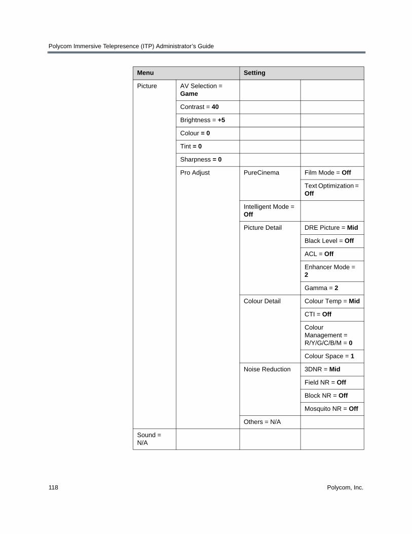
Polycom Immersive Telepresence (ITP) Administrator’s Guide
118 Polycom, Inc.
Picture AV Selection = Game
Contrast = 40
Brightness = +5
Colour = 0
Tint = 0
Sharpness = 0
Pro Adjust PureCinema
Film Mode = Off
Text Optimization = Off
Intelligent Mode = Off
Picture Detail DRE Picture = Mid
Black Level = Off
ACL = Off
Enhancer Mode = 2
Gamma = 2
Colour Detail Colour Temp = Mid
CTI = Off
Colour Management = R/Y/G/C/B/M = 0
Colour Space = 1
Noise Reduction 3DNR = Mid
Field NR = Off
Block NR = Off
Mosquito NR = Off
Others = N/A
Sound = N/A
Menu Setting

Maintaining the ITP Room
Polycom, Inc. 119
To check the display settings at TPX sites using versions earlier than version 2.0:
>> For North America displays, these are the settings:
Power Control
Energy Save = Off
No Signal Off = Disable
No Operation Off = Disable
Sleep Timer = Off
Setup = N/A
Home Media Gallery = N/A
Menu Setting
Channel N/A
Favorite N/A
Input N/A
Home Media Gallery N/A
Menu Setting

Polycom Immersive Telepresence (ITP) Administrator’s Guide
120 Polycom, Inc.
Setup Option HDMI Input Signal Type = PC
Video = Color-4
Audio = AUTO
HDMI Control Settings Input Setting = Off
Orbiter = Off (N/A in EMEA)
Label Input = N/A
Picture AV Selection = Standard
Contrast = 40
Brightness = +5
Red = 0
Green = 0
Blue = 0
Sound N/A
Power Control Energy Save = Off
Sleep Timer = Off
Favorite Setup = N/A
Menu Setting
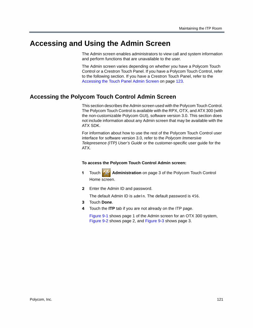
Maintaining the ITP Room
Polycom, Inc. 121
Accessing and Using the Admin ScreenThe Admin screen enables administrators to view call and system information and perform functions that are unavailable to the user.
The Admin screen varies depending on whether you have a Polycom Touch Control or a Crestron Touch Panel. If you have a Polycom Touch Control, refer to the following section. If you have a Crestron Touch Panel, refer to the Accessing the Touch Panel Admin Screen on page 123.
Accessing the Polycom Touch Control Admin Screen
This section describes the Admin screen used with the Polycom Touch Control. The Polycom Touch Control is available with the RPX, OTX, and ATX 300 (with the non-customizable Polycom GUI), software version 3.0. This section does not include information about any Admin screen that may be available with the ATX SDK.
For information about how to use the rest of the Polycom Touch Control user interface for software version 3.0, refer to the Polycom Immersive Telepresence (ITP) User’s Guide or the customer-specific user guide for the ATX.
To access the Polycom Touch Control Admin screen:
1 Touch Administration on page 3 of the Polycom Touch Control
Home screen.
2 Enter the Admin ID and password.
The default Admin ID is admin. The default password is 456.
3 Touch Done.
4 Touch the ITP tab if you are not already on the ITP page.
Figure 9-1 shows page 1 of the Admin screen for an OTX 300 system, Figure 9-2 shows page 2, and Figure 9-3 shows page 3.

Polycom Immersive Telepresence (ITP) Administrator’s Guide
122 Polycom, Inc.
Figure 9-1 Polycom Touch Control Admin Screen Page 1 — OTX 300 Example
Figure 9-2 Polycom Touch Control Admin Screen Page 2 — OTX 300 Example
Figure 9-3 Polycom Touch Control Admin Screen Page 3 — OTX 300 Example

Maintaining the ITP Room
Polycom, Inc. 123
Accessing the Touch Panel Admin Screen
This section describes the Admin screen used with the Crestron Touch Panel supplied by Polycom. The Touch Panel is available with the RPX, OTX, TPX, and ATX 300 (with the non-customizable Polycom GUI), software version 2.7.1 and earlier. This section does not include information about any Admin screen that may be available with the ATX SDK.
For information about how to use the rest of the Touch Panel user interface for software version 2.7.1 and earlier, refer to the Polycom RPX User Guide, Polycom OTX 300 User Guide, Polycom TPX User Guide, or the customer-specific user guide for the ATX.
With the Touch Panel, you can access the full Admin screen or you can choose to access only the display on/off controls and the OTX content monitor lift up/down controls. This section describes both of these options.
To access the full Touch Panel Admin screen:
>> Touch on the Touch Panel for seven seconds.
Figure 9-4 shows a sample Admin screen for an RPX 200 Series. This screen will appear slightly different if you have an RPX 400 Series. For example, four bars at the top of the screen and four codecs will be displayed for the RPX 400 Series.
Figure 9-4 Touch Panel Admin Screen — RPX 200 Example

Polycom Immersive Telepresence (ITP) Administrator’s Guide
124 Polycom, Inc.
Figure 9-5 shows a sample Admin screen for a TPX 306M (the Admin screens for the OTX and the ATX with the Polycom GUI are very similar). Note that the codec that was previously labeled as Left on this TPX screen is now labeled Secondary.
Figure 9-5 Touch Panel Admin Screen — TPX 306M Example
To access only the display on/off controls and the OTX content monitor lift up/down controls:
>> Touch on the Touch Panel for five seconds.
A pop-up window appears.
Using the Admin Screen
You can use the Polycom Touch Control Admin screen and the Touch Panel Admin screen to do the following:
• Power the displays on or off.
To access the display controls with the Crestron Touch Panel, touch on the Touch Panel Start screen for five seconds.
• Show or hide the video from the cameras on the displays.
Note that in order to show video on the displays, the displays must first be powered on.

Maintaining the ITP Room
Polycom, Inc. 125
• Initialize the displays to optimal settings (OTX and TPX systems only with the Polycom Touch Control or the Crestron Touch Panel).
• Lock or unlock the IR for the display remote controls (OTX and TPX systems only; also depends on which displays are used with the system).
• Enable the IR for the projectors so that the projector remote controls can be used to service or configure the projectors (RPX systems only with the Polycom Touch Control or the Crestron Touch Panel).
• Change the call speeds.
Entering a call speed on the Admin screen will force the system to override the preferred call speed set in the HDX Call Preference screen and use the one specified here. (For more information about setting the call speed, see the note on page 47.)
• Specify either 720p60 or 1080p30 as the video format preference.
• Place an internal loopback call.
• Hang up the current call.
• Raise or lower the OTX tabletop content monitors (OTX systems only with the Polycom Touch Control or the Crestron Touch Panel).
To access OTX content monitor controls with the Touch Panel, touch on the Touch Panel Start screen for five seconds.
In addition, you can use the Crestron Touch Panel Admin screen to view the following system information. (With the Polycom Touch Control, you can view the system information by touching System on page 2 of the Polycom Touch Control Home screen.)
• View the IP address, system name, model, and software version for each codec.
• View the call statistics, including the call speed and format.
• View the IP address for the System Controller.
• View the software version for the System Controller.
• View the software version for the Touch Panel.

Polycom Immersive Telepresence (ITP) Administrator’s Guide
126 Polycom, Inc.
Using Telnet Commands to Access the System Controller
The following table lists the commands that you can invoke via TCP/IP (Telnet) connection to the System Controller. The traditional Telnet port (port 23) or the Toolbox application can be used to invoke the commands.
To enter a comment, use this syntax: userprogcmd “<cmd>”. For example, to set the default call speed to 2MB, enter userprogcmd “default 1920”.
Note that the call speed set by Telnet command does not override the preferred call speed set in the HDX Call Preference screen. However, if the call speed for a site is set to Auto, the call speed specified by Telnet command will be used. (For more information about setting the call speed, see the note on page 47.)
Command Action
debug on Turns on debug statements for logging and troubleshooting
debug off Turns off debug statements
display on Powers on all projectors (RPX only)
display off Powers off all projectors (RPX only)
displays on Powers on all displays (OTX and TPX only)
displays off Powers off all displays (OTX and TPX only)
projector lamp report Reports lamp hours for all projectors (RPX only)
loopback Enters loopback mode
hang up Hangs up the video call
default 1536 or default 1.5 MB
Sets the default call speed to 1.5 MB
default 1920 or default 2MB Sets the default call speed to 2MB
default 3072 or default 3MB Sets the default call speed to 3MB
default 4096 or default 4MB Sets the default call speed to 4MB
default 6144 or default 6MB Sets the default call speed to 6MB
1080p30 Sets the video format to 1080p30 on all codecs
720p60 Sets the video format to 720p60 on all codecs
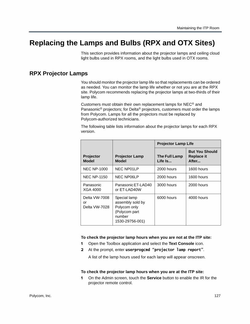
Maintaining the ITP Room
Polycom, Inc. 127
Replacing the Lamps and Bulbs (RPX and OTX Sites)This section provides information about the projector lamps and ceiling cloud light bulbs used in RPX rooms, and the light bulbs used in OTX rooms.
RPX Projector Lamps
You should monitor the projector lamp life so that replacements can be ordered as needed. You can monitor the lamp life whether or not you are at the RPX site. Polycom recommends replacing the projector lamps at two-thirds of their lamp life.
Customers must obtain their own replacement lamps for NEC® and Panasonic® projectors; for Delta® projectors, customers must order the lamps from Polycom. Lamps for all the projectors must be replaced by Polycom-authorized technicians.
The following table lists information about the projector lamps for each RPX version.
To check the projector lamp hours when you are not at the ITP site:
1 Open the Toolbox application and select the Text Console icon.
2 At the prompt, enter userprogcmd “projector lamp report”.
A list of the lamp hours used for each lamp will appear onscreen.
To check the projector lamp hours when you are at the ITP site:
1 On the Admin screen, touch the Service button to enable the IR for the projector remote control.
Projector Model
Projector Lamp Model
Projector Lamp Life
The Full Lamp Life Is...
But You Should Replace it After...
NEC NP-1000 NEC NP01LP 2000 hours 1600 hours
NEC NP-1150 NEC NP06LP 2000 hours 1600 hours
Panasonic XGA 4000
Panasonic ET-LAD40 or ET-LAD40W
3000 hours 2000 hours
Delta VW-7008 or Delta VW-7028
Special lamp assembly sold by Polycom only (Polycom part number 1530-29756-001)
6000 hours 4000 hours
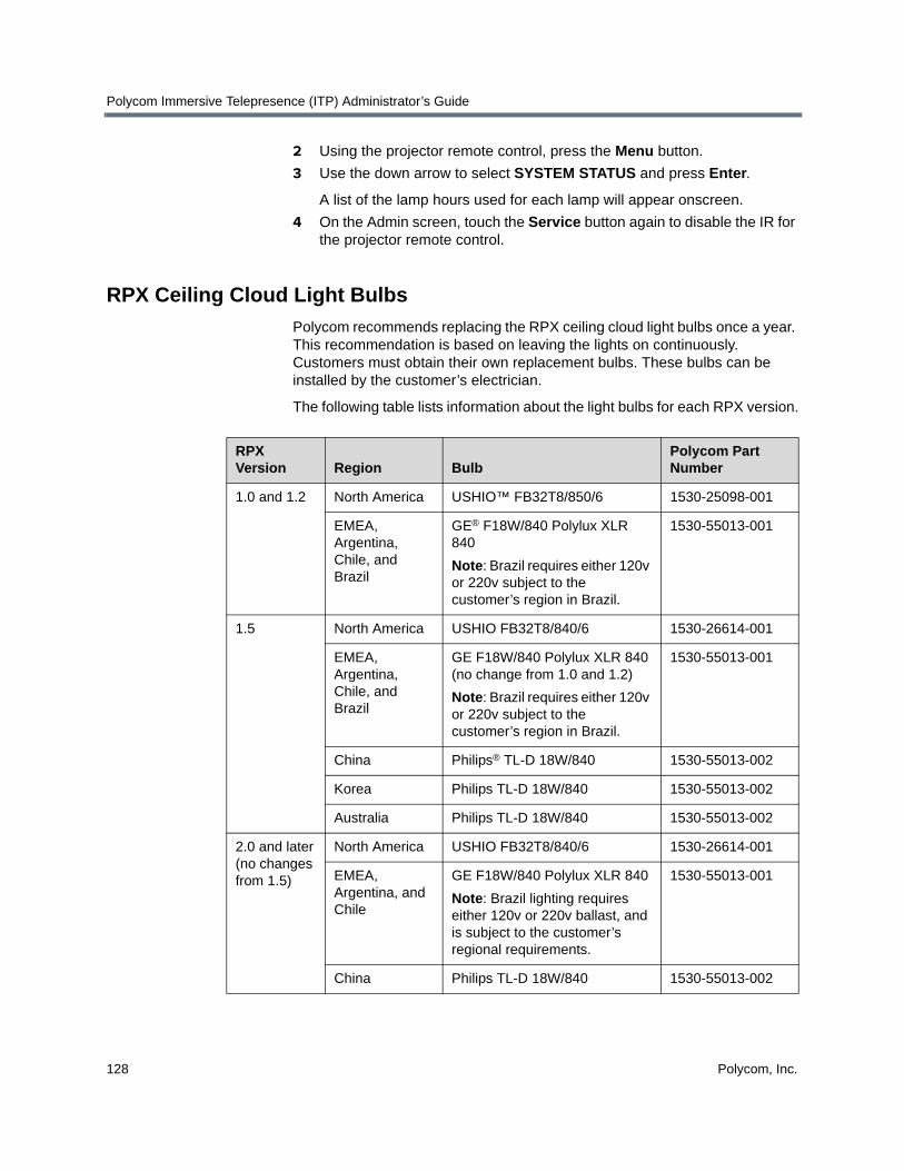
Polycom Immersive Telepresence (ITP) Administrator’s Guide
128 Polycom, Inc.
2 Using the projector remote control, press the Menu button.
3 Use the down arrow to select SYSTEM STATUS and press Enter.
A list of the lamp hours used for each lamp will appear onscreen.
4 On the Admin screen, touch the Service button again to disable the IR for the projector remote control.
RPX Ceiling Cloud Light Bulbs
Polycom recommends replacing the RPX ceiling cloud light bulbs once a year. This recommendation is based on leaving the lights on continuously. Customers must obtain their own replacement bulbs. These bulbs can be installed by the customer’s electrician.
The following table lists information about the light bulbs for each RPX version.
RPX Version Region Bulb
Polycom Part Number
1.0 and 1.2 North America USHIO™ FB32T8/850/6 1530-25098-001
EMEA,Argentina, Chile, and Brazil
GE® F18W/840 Polylux XLR 840
Note: Brazil requires either 120v or 220v subject to the customer’s region in Brazil.
1530-55013-001
1.5 North America USHIO FB32T8/840/6 1530-26614-001
EMEA,Argentina, Chile, and Brazil
GE F18W/840 Polylux XLR 840 (no change from 1.0 and 1.2)
Note: Brazil requires either 120v or 220v subject to the customer’s region in Brazil.
1530-55013-001
China Philips® TL-D 18W/840 1530-55013-002
Korea Philips TL-D 18W/840 1530-55013-002
Australia Philips TL-D 18W/840 1530-55013-002
2.0 and later(no changes from 1.5)
North America USHIO FB32T8/840/6 1530-26614-001
EMEA,Argentina, and Chile
GE F18W/840 Polylux XLR 840
Note: Brazil lighting requires either 120v or 220v ballast, and is subject to the customer’s regional requirements.
1530-55013-001
China Philips TL-D 18W/840 1530-55013-002
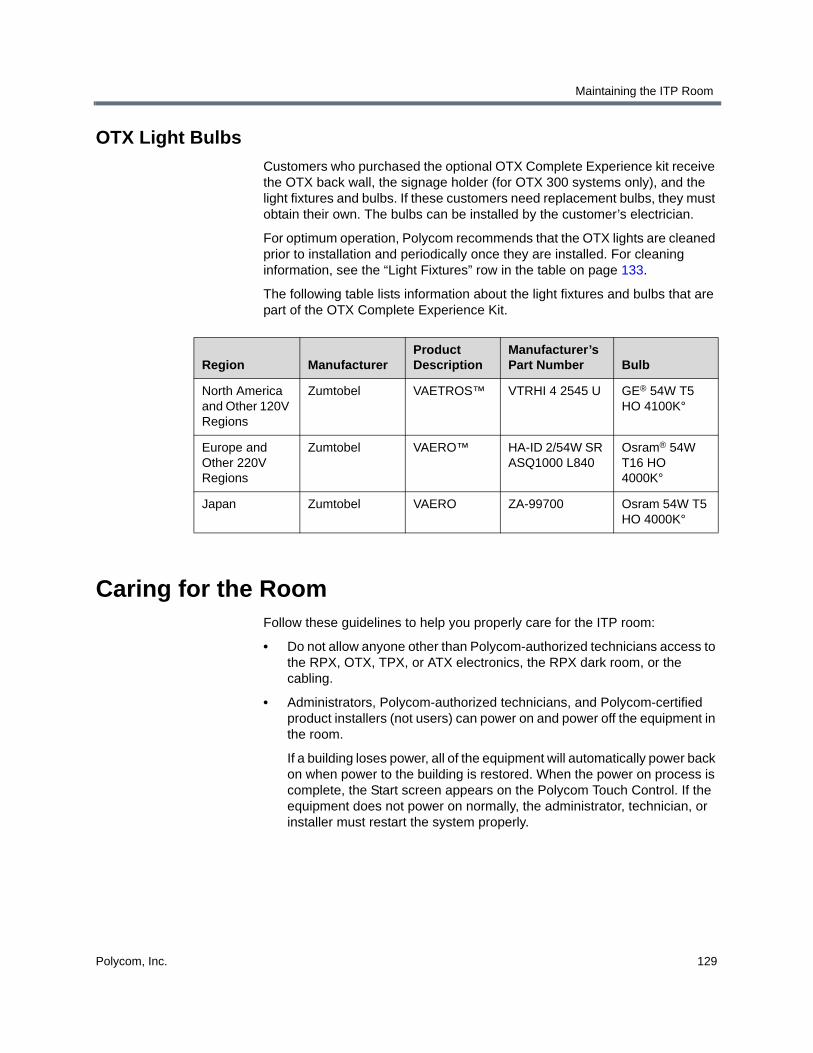
Maintaining the ITP Room
Polycom, Inc. 129
OTX Light Bulbs
Customers who purchased the optional OTX Complete Experience kit receive the OTX back wall, the signage holder (for OTX 300 systems only), and the light fixtures and bulbs. If these customers need replacement bulbs, they must obtain their own. The bulbs can be installed by the customer’s electrician.
For optimum operation, Polycom recommends that the OTX lights are cleaned prior to installation and periodically once they are installed. For cleaning information, see the “Light Fixtures” row in the table on page 133.
The following table lists information about the light fixtures and bulbs that are part of the OTX Complete Experience Kit.
Caring for the RoomFollow these guidelines to help you properly care for the ITP room:
• Do not allow anyone other than Polycom-authorized technicians access to the RPX, OTX, TPX, or ATX electronics, the RPX dark room, or the cabling.
• Administrators, Polycom-authorized technicians, and Polycom-certified product installers (not users) can power on and power off the equipment in the room.
If a building loses power, all of the equipment will automatically power back on when power to the building is restored. When the power on process is complete, the Start screen appears on the Polycom Touch Control. If the equipment does not power on normally, the administrator, technician, or installer must restart the system properly.
Region ManufacturerProduct Description
Manufacturer’s Part Number Bulb
North America and Other 120V Regions
Zumtobel VAETROS™ VTRHI 4 2545 U GE® 54W T5 HO 4100K°
Europe and Other 220V Regions
Zumtobel VAERO™ HA-ID 2/54W SR ASQ1000 L840
Osram® 54W T16 HO 4000K°
Japan Zumtobel VAERO ZA-99700 Osram 54W T5 HO 4000K°

Polycom Immersive Telepresence (ITP) Administrator’s Guide
130 Polycom, Inc.
• To clean the components in the room, refer to the this table:
Component Recommended Cleaning Procedure
Acoustic panels OTX: If the acoustic panel fabric becomes soiled, gently rub the affected areas with a clean, lint-free cloth and warm soapy water. Test all cleaning procedures on a small inconspicuous area. Do not immerse the panels in water. Do not rub wet ink as this may cause smudging.
Cameras RPX: Do not clean the cameras, which are located in the center of the large display screens. Doing so may mis-align the cameras, resulting in compromised video.
OTX: Do not clean the camera(s), which are located at the top of the video wall behind the camera shroud. Doing so may mis-align the camera(s), resulting in compromised video.
TPX: Do not clean the cameras, which are located at the top of the credenza behind the camera shield. Doing so may mis-align the cameras, resulting in compromised video.
ATX: Do not clean the cameras, which are located above the displays. Doing so may mis-align the cameras, resulting in compromised video.
Camera shield/Camera shroud
OTX and TPX: Using a soft sponge, a wool cloth, or chamois, wipe the polycarbonate shield with lukewarm water containing a neutral detergent, such as Formula 409®, Windex®, or Joy®. Be very careful not to scratch the polycarbonate shield. Do not leave cleaners on for a long period, or apply cleaners in direct sunlight or at elevated temperatures. Be sure to rinse off cleaners with lukewarm water. Never use razor blades, scrapers, squeegees, or brushes.
Carpet RPX: Vacuum frequently. Get a professional cleaning every 12 to 18 months, depending on the amount of activity in the room. Professional cleaning should be done by hot water extraction (commonly called “steam” cleaning), and should be performed by an IICRC (Institute of Inspection, Cleaning and Restoration Certification) certified firm. For spot cleaning, use Shaw® R2X Stain and Soil Remover, if available, or an equivalent product that is safe for wool. Pretest a small area before proceeding.
OTX: For InterfaceFLOR™ and other carpeting, vacuum daily using a vacuum cleaner with a cylinder brush. Treat spots and spills as soon as they occur. Always try to remove the spot with water before using a spotting solution.
When vacuuming, be careful not to bump into the video wall. Doing so may mis-align the camera, resulting in compromised video.

Maintaining the ITP Room
Polycom, Inc. 131
Ceiling Microphone Arrays
All rooms: Gently dust with a feather duster as needed.
Chairs RPX and TPX: Gently dust chairs regularly with a dry, soft cloth. For cleaning up spills or stains, remove as much soil or stain as possible by brushing or wiping with a soft cloth. Use warm water and mild soap to remove any remaining residue. Do not use furniture polishes, oils, solvents, abrasive cleaners, ammonia, or wax as they may cause the leather to dry out and eventually crack.
Chairs (continued) OTX: For Herman Miller® Eames® chairs, vacuum or dust the leather frequently with a clean, dry cloth. If the leather is soiled, wipe it with a damp, soft cloth and a lather of any mild soap and a minimum amount of lukewarm water. Do not spot clean leather; clean the entire surface. Wipe it clean with a damp cloth and dry it with a clean, soft cloth.
For spots and spills, wipe the excess liquid immediately with a clean cloth or sponge, and let the leather air dry. If further cleaning is necessary, sponge the entire leather surface with clean, lukewarm water. Let the leather air dry; never use a hair dryer or other heat source to dry leather.
For stubborn spots and stains on the leather, apply a mild, nonabrasive soap solution with a clean, wet sponge. Rinse well and let it air dry. For butter, oil, or grease, wipe the leather with a clean, dry cloth and let the remainder of the oil dissipate into the leather. Do not apply water or try to wash a grease spot.
Do not use saddle soap, cleaning solvents, oils, furniture polishes, varnishes, abrasive cleaners, detergents, or ammonia on leather; they will ruin the finish, causing it to become sticky and cracked.
For regular cleaning of the polished aluminum chair components, apply a pre-softened paste wax to the polished aluminum following the manufacturer’s instructions. In humid atmospheres near salt water, apply the wax once a month. In other areas, apply the wax every three months to maintain the appearance of the aluminum.
Clouds RPX: Vacuum or lightly brush to remove dust and grime. Spot clean with an upholstery shampoo or the foam from a mild detergent. In all cases, pretest a small area before proceeding. Use a professional furniture cleaning service when needed.
Content monitors RPX, OTX, and TPX: Gently wipe the screens with a very soft, lint-free cloth (microfiber is recommended) and a liquid cleaning solution that contains water, vinegar and water, or isopropyl alcohol. Spray the liquid cleaning solution directly on the cloth and clean in a circular motion. Do not use cleaners that contain acetone, ethyl alcohol, ethyl acid, ammonia, or methyl chloride.
Component Recommended Cleaning Procedure

Polycom Immersive Telepresence (ITP) Administrator’s Guide
132 Polycom, Inc.
Dark room (below displays)
RPX: Vacuum or lightly brush to remove dust and grime. Spot clean with a mild solvent, an upholstery shampoo, or the foam from a mild detergent. In all cases, pretest a small area before proceeding. Use a professional furniture cleaning service when needed.
Data ports/Collaboration Tanks
RPX (data ports) and OTX (Collaboration Tanks): Dust with a feather duster and keep free of debris. If a spill occurs in or around a data port or Collaboration Tank, wipe it up immediately. If you notice data collaboration problems after a spill, contact your organization’s IT department.
Displays (large display screens at front of room)
RPX: Before beginning to clean the display screens, be aware that the cameras are located behind the screens. Be very careful not to mis-align the cameras. Doing so may result in compromised video.
For slightly dusty screens, dust with a feather duster. You can also lightly vacuum the screens using a brush attachment with bristles that are not too soft, but that will not scratch the surface (using a new brush is recommended). Move the brush in the direction of the profiles. For example, for the front side (lenticular profile), work up and down.
For dirty screens, spray a window cleaner with ammonia (not alcohol) onto a painting pad until the pad is lightly moistened:
Move the pad in the direction of the profiles. You must clean the whole screen; otherwise, a difference between the treated and untreated areas will appear. Wipe the screens dry with a dry painting pad, working in the same direction as you used for cleaning them. If the pad becomes too wet, wipe it with water-absorbent paper. It is important that you completely dry the screens after cleaning them. You can also use a hair dryer to dry the screens, but you must set it on the lowest setting and hold it at a proper distance from the screens.
Never use cleaning agents with solvents as these may destroy the screens. Never rub hard or persistently on the screens. This will cause deformations in the surface which will appear as stains and may also mis-align the cameras.
Component Recommended Cleaning Procedure

Maintaining the ITP Room
Polycom, Inc. 133
Displays (large display screens at front of room)
OTX: Gently wipe the screen(s) with a very soft, lint-free cloth (microfiber is recommended) and a liquid cleaning solution that contains water, vinegar and water, or isopropyl alcohol, such as Monster™ screen cleaner. Spray the liquid cleaning solution directly on the cloth and clean in a circular motion. Do not use cleaners that contain acetone, ethyl alcohol, ethyl acid, ammonia, or methyl chloride.
TPX: To clean the screens: Gently wipe the screens with Monster screen cleaner or CleanDr® screen cleaner and a micro fiber cloth. Do not use tissue or any other type of cloth. The surface of the screens is easily scratched, so do not rub it or hit it with a hard object. Do not clean the screens with water; water droplets could enter into the product, resulting in malfunction.
To clean the vents: Use a vacuum cleaner periodically to remove the dust buildup on the vents on the rear of the displays. Set the vacuum cleaner to its weakest setting when doing this. Using the displays without cleaning them of dust may cause the internal temperature to increase, resulting in possible breakdown or fire.
Light fixtures OTX: Turn off the power and then wipe the fixtures with a soft, lint-free cloth. Clean the lenses with a dry cloth only.
Polycom Touch Control or Crestron Touch Panel
All rooms: Keep the touch screen free of dirt, dust, or other materials that could degrade the optical properties. For best cleaning results, apply any commercially available non-ammonia glass cleaner to a clean, non-abrasive cloth, and wipe the Polycom Touch Control or Crestron Touch Panel with the cloth. Then, with a dry area of the cloth, dry off the touch screen. Because the bezels may not provide a water-tight seal, avoid getting moisture beneath the bezels.
Projectors RPX: If your system is under a maintenance agreement, only Polycom-certified technicians can perform maintenance on the projectors. If your system is not under a maintenance agreement, refer to the documentation that came with the projectors for maintenance instructions, such as how to clean the projector lenses and how to replace the projector lamps and air filters. For more information about the projector lamps, refer to Replacing the Lamps and Bulbs (RPX and OTX Sites) on page 127.
Rear wall RPX: For graphic artwork: Vacuum with a soft brush attachment. Be careful not to scratch the artwork. Do not use water or any other liquid on the artwork. For bottom of rear wall: Vacuum or lightly brush to remove dust and grime. Spot clean with a mild solvent, an upholstery shampoo, or the foam from a mild detergent. In all cases, pretest a small area before proceeding. Use a professional furniture cleaning service when needed.
OTX: Wipe the rear wall clean with a soft cloth dampened with water or an all purpose cleaner.
Component Recommended Cleaning Procedure

Polycom Immersive Telepresence (ITP) Administrator’s Guide
134 Polycom, Inc.
Simulated wood furniture (vinyl-covered MDF)
RPX and TPX: Wipe with soap and water using a gentle brush or sponge. You can also wipe with a soft cloth dampened with window cleaner or an all purpose cleaner. Do not use caustic, abrasive, or oil-based cleaning products.
Table OTX: To clean the laminate surface, use a damp cloth or sponge and a mild soap or detergent. Remove difficult stains, such as coffee or tea, using a mild household cleaner mixed with baking soda. Recommended cleaners include Magic Complete® countertop spray, Formula 409, Windex, and Fantastik®. Always rinse and wipe the laminate surfaces dry after cleaning.
For information on how to clean the RPX and TPX tables, see the “Simulated wood furniture (vinyl-covered MDF)” row in this table.
Component Recommended Cleaning Procedure

Polycom, Inc. 135
Index
Symbols
.pup file 2
.spz file 13
.vtz file 17
Numerics
1080p30, selecting as video format preference 29
720p60, selecting as video format preference 29
A
acoustic panels, cleaning 130Active Directory 70address book, Telepresence Tool 52Admin screen
accessing with Polycom Touch Control 121accessing with Touch Panel 123using with Touch Control or Touch Panel 124
AfterHours field, in System_Config.ini file 24ATX
selecting control device with Telepresence Tool 46
selecting video format with Telepresence Tool 39
showing or hiding splash screen 45upgrading software for 1
Audio Speed Dial button, for Help Desk 84, 90audio, verifying with Telepresence Tool 51automatic layout mode 94auxiliary content button, adding a label to 32
B
bulbsreplacing OTX 129replacing RPX 128
C
calendaringSee Polycom Conferencing for Microsoft Outlook
call rate, See call speed
call speedchanging on Admin screen 125defaults based on codec type 47setting on HDX Call Preference screen 47setting on New Contact screen with Touch
Control 79, 81, 88setting on New Contact screen with Touch
Panel 86setting when importing System_Config.ini file
with Touch Control 75setting when importing System_Config.ini file
with Touch Panel 84setting with Telepresence Tool 47setting with Telnet commands 126specifying in System_Config.ini file 24viewing on Admin screen 125
camera shield, cleaning 130camera shroud, cleaning 130cameras
aligning with Telepresence Tool 48cleaning 130configuring NTSC or PAL setting 107controlling with Telepresence Tool 48enabling close up or wide shot views 35enabling document camera 30matching with Telepresence Tool 48security 107taking snapshots with Telepresence Tool 49, 50
carpet, cleaning 130Ceiling Microphone Arrays, calibrating 48chairs, cleaning 131Cisco Unified Communications Manager,
enabling for TIP 65Classic UI
definition 27selecting 26
cleaning, ITP rooms 129close up camera view 35clouds
cleaning 131replacing bulbs 128

Polycom Immersive Telepresence (ITP) Administrator’s Guide
136 Polycom, Inc.
CMAadding members to existing groups 69affect on UI behavior 27configuring ITP rooms to access 66creating groups and associating members 69creating ITP rooms and associating endpoints
68integrating ITP rooms 66registering ITP rooms 61
codecsassociating with rooms using CMA 68automatically adding to global directory 61configuring to access CMA 66configuring to access RMX 100hiding Secondary in Microsoft environments 71manually adding to global directory 61pairing Primary codec with Polycom Touch
Control 55registering with gatekeeper 61
Collaboration Tanks, cleaning 132conference profile, configuring on RMX 98content
adding label to button 32selecting document camera or PC as source
31viewing on displays when not in a call (OTX
only) 32content monitors
automatically lifting (OTX only) 34cleaning 131configuring for RPX 40enabling or disabling the lifts for (OTX only) 33selecting with Telepresence Tool 39
Converged Management Application, See CMACUCM, enabling for TIP 65customer support v
D
dark room, cleaning 132data ports, cleaning 132date, setting 3DBA, disabling 104DefaultCallSpeed field, in System_Config.ini file
24dialing order, for TIP 66dimming, disabling for TPX displays 34directory
CMAadding members to existing groups 69configuring ITP rooms to access 66creating groups and associating members 69creating rooms and associating endpoints 68integrating ITP rooms with 66
localadding sites not registered to CMA 85adding Virtual Meeting Room to 103configuring entries 85configuring groups 89configuring single site entries for ITP sites 87configuring single site entries for non-ITP
sites 86managing 82maximum entries supported 85using Directory Downgrade tool 53
displayschecking alignment with Telepresence Tool 51checking settings 110cleaning 132, 133disabling dimming for TPX 34settings for OTX 111settings for TPX 112
Do Not Disturb, setting in System_Config.ini file 24
document cameraenabling 30selecting as content source 31
documentation, related ivDoNotDisturb field, in System_Config.ini file 24downgrading, using Directory Downgrade tool 53Dynamic Bandwidth Allocation, disabling 104
E
endpoints, associating 68energy save feature, disabling on TPX 34Enhanced UI
definition 26selecting 26
F
Favoritesadding sites not registered to CMA 75adding Virtual Meeting Room to 103configuring 75configuring groups 81configuring single site entries for ITP sites 79configuring single site entries for non-ITP sites
78importing from HDX 76list of configurable endpoints 73

Index
Polycom, Inc. 137
managing 73maximum entries supported 76
firmwareconfirming for System Controller 11confirming for Touch Panel 18downloading for System Controller 12downloading for Touch Panel 19
furniture, cleaning 134
G
gatekeeper, configuring for use with ITP systems 61
group dialingdefinition 94enabling 100
groupsadding members 69configuring in Favorites 81configuring in local directory 89creating in CMA 69
H
H.323 extension, entering for codecs with Touch Control 79, 87
H.323 gatekeeper, configuring for use with ITP systems 61
HD video, enabling on Lync Server 70HDX
accessing logs 109configuring for user-initiated multipoint
conferences 94configuring to access RMX 100importing Favorites from 76importing local directory from 85password 23, 51setting up naming on 96software .pup file 2upgrading software 1using Directory Downgrade tool 53
HDX ITP system communication, enabling 4HDXpassword field, in System_Config.ini file 23Help Desk
automatically creating button for 84configuring number for with Touch Control 77configuring number for with Touch Panel 85
I
IP address, entering for codecs with Touch Control 79, 87
ISDN numbers 76, 85ITP rooms
configuring for use with Lync Server 70configuring to access CMA 66configuring to access RMX 100creating groups and associating members
using CMA 69creating with CMA 68enabling optional features 26integrating with CMA directory 66maintaining 105managing local directory 82
K
key code 2
L
label, adding to auxiliary content button 32lamps, replacing 127LAN, configuring 6LDAP 67license number 2light bulbs
replacing for OTX 129replacing for RPX 128
light fixtures, cleaning 133local directory, See directorylogs
accessing for HDX 109accessing for Polycom Touch Control 109accessing for RMX 109
Lync Serverconfiguring ITP systems for use with 70, 71creating conference room user accounts 70enabling HD video on 70hiding Secondary codecs 71
M
maintenanceaccessing HDX and RMX logs 109accessing HDX, RMX, and Polycom Touch
Control logs 109acdessing the security camera 107caring for the room 129checking display settings 110powering up and down remotely 106replacing lamps and bulbs 127using Telnet commands 126using the Admin screen 121
Polycom Immersive Telepresence (ITP) Administrator’s Guide
138 Polycom, Inc.
Meeting Composerdefinition 93enabling 100
members, associating 69microphones
cleaning 131verifying audio with Telepresence Tool 51
Microsoft environmentconfiguring ITP systems for use with 70, 71creating conference room user accounts 70enabling HD video on 70hiding Secondary codecs 71
MLAconfiguring for automatic layout mode 94configuring for user-initiated multipoint
conferences 94multipoint conferences
configuring the MLA, HDX, and RMX for use with 94
enabling group dialing 100enabling Meeting Composer and Multipoint
Speed Dial 100enabling Polycom Conferencing for Microsoft
Outlook 98enabling Single Touch Multipoint 102enabling user-initiated 93using Polycom Conferencing for Microsoft
Outlook 93Multipoint Layout Application, See MLAMultipoint Speed Dial
definition 94enabling 100
N
name, of siteentering for ITP sites with Touch Control 79, 87entering for non-ITP sites with Touch Control
79entering for non-ITP sites with Touch Panel 86maximum number of characters for non-ITP
sites with Touch Control 79maximum number of characters for non-ITP
sites with Touch Panel 86naming conventions, for HDX codecs 96NTSC setting, configuring 107
O
operating system, loading for Polycom Touch Control 15
optionsadding label to auxiliary content button 32disabling dimming on TPX LG displays 34
enabling 26enabling close up or wide shot camera views
35enabling document camera 30key code 2selecting document camera or PC as content
source 31selecting Enhanced or Classic UI 26selecting video format preference 29specifying in System_Config.ini file 25
Options field, in System_Config.ini file 25OTX
automatically lifting content monitors 34display settings 111enabling or disabling lifts for content monitors
33replacing light bulbs 129viewing content on displays when not in a call
32
P
pairingPolycom Touch Control with Primary codec 55Polycom Touch Control with System Controller
58unpairing 60
PAL setting, configuring 107password
for HDX 23for RMX 101for VMR 102updating on HDX codecs 51
PC, selecting as content source 31Polycom Conferencing for Microsoft Outlook
definition 93enabling 98setting date and time 3
Polycom Touch Controlaccessing logs 109Admin screen 121cleaning 133loading operating system and software 15managing Favorites 73pairing with Primary HDX codec 55pairing with System Controller 58unpairing 60
powering up and down remotely 106projectors
aligning with Telepresence Tool 48checking lamp hours 127cleaning 133replacing lamps 127
Index
Polycom, Inc. 139
R
rear monitoring camera 107related documentation ivRMX
accessing logs 109affect on UI behavior 27configuring for user-initiated multipoint
conferences 94configuring ITP suite to access 100configuring the conference profile 98creating Virtual Meeting Room on 102
Room Continuous Presencedefinition 94selecting 101
rooms, adding with CMA 68RPX
configuring content monitors 40security camera 107selecting document camera or PC as content
source 31RTV 70
S
sample sites, deleting 82, 89security camera, accessing 107serial number 2single site
configuring directory entry for 86configuring Favorite for 78
Single Touch Multipointdefinition 94enabling 102
SIP, configuring for ITP systems 63sites
adding single site entry in Favorites 78adding single site entry in local directory 86deleting sample sites 82, 89
sleep timersetting date and time 3setting in System_Config.ini file 24
SleepTimer field, in System_Config.ini file 24snapshots, taking with Telepresence Tool 49, 50software
loading for Polycom Touch Control 15loading for System Controller 12loading for Touch Panel 16upgrading HDX 1
speakers, verifying audio with Telepresence Tool 51
Speed Dial buttonsadding with Touch Panel 91changing the order of 92configuring for VMRs 104configuring with Touch Panel 90creating for ITP suite with Touch Panel 92creating to call multiple sites at one time 94importing from System_Config.ini file for Touch
Control 74importing from System_Config.ini file with
Touch Panel 83list of configurable endpoints 82maximum number supported 90
speed, call, See call speedsplash screen, showing or hiding for ATX 45support vSystem Controller
accessing with Telnet commands 126configuring 5confirming firmware version 11connecting through a serial connection 7connecting through an IP connection 9connecting to from Address Book 10downloading firmware 12downloading System_Config.ini file 25loading software 12pairing with Polycom Touch Control 58
System_Config.ini filedownloading onto System Controller 25editing 21importing speed dials for Touch Control 74importing speed dials with Touch Panel 83
SystemModel field, in System_Config.ini file 23SystemName field, in System_Config.ini file 23
T
table, cleaning 134tabletop content monitors, See content monitorsTelepresence Interoperability Protocol, See TIPtelepresence support vTelepresence Tool
configuring HDX codecs with 44configuring RPX content monitors 40connecting to the codecs with 38functions available through 48installing 37selecting content monitor 39selecting main display 38selecting model 38using address book 52using HDX Directory Downgrade tool 53
Telnet commands 126
Polycom Immersive Telepresence (ITP) Administrator’s Guide
140 Polycom, Inc.
time, setting 3, 4TIP, enabling 64Touch Panel
Admin screen 123cleaning 133confirming firmware version 18downloading firmware 19loading software 16
TPXdisabling dimming on displays 34display settings 112limitation 104
U
UIaffect on behavior by RMX and CMA
configuration 27selecting Enhanced or Classic 26
unpairing 60USB storage device, using to load Touch Panel
software 15user interface, See UIuser-initiated multipoint conferences, See
multipoint conferences
V
VARSdefinition 94selecting 101
video format preference 29video, enabling HD video on Lync Server 70Virtual Meeting Room, See VMRVMR
adding to Favorites 103adding to local directory 103address 103calling with Single Touch Multipoint 94configuring Speed Dial buttons for 104creating on the RMX 102TPX limitation 104
Voice Activated Room Switchingdefinition 94selecting 101
W
walls, cleaning 133web camera 107wide shot camera view 35