Embed Size (px)
Citation preview
8/12/2019 3. Transmissions
http://slidepdf.com/reader/full/3-transmissions 1/52
Rev. A Sept 18, 2007 3-4
Transmissions
Model S64F Helicopter

8/12/2019 3. Transmissions
http://slidepdf.com/reader/full/3-transmissions 2/52
3-5Rev. A Sept 18, 2007
Main Gear Box
8/12/2019 3. Transmissions
http://slidepdf.com/reader/full/3-transmissions 3/52
3-6Rev. A Sept 18, 2007
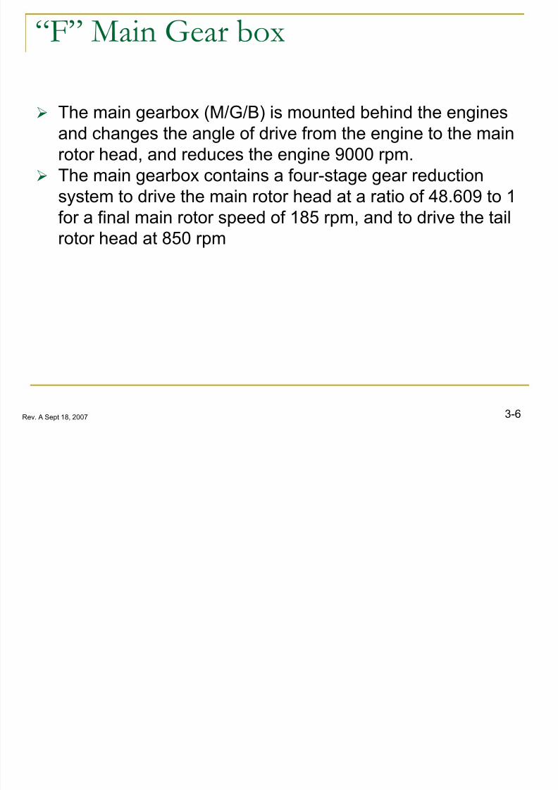
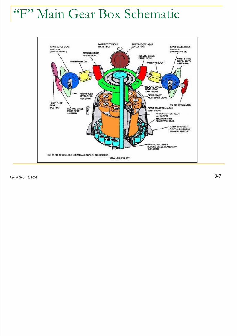
“F” Main Gear box
The main gearbox (M/G/B) is mounted behind the engines
and changes the angle of drive from the engine to the main
rotor head, and reduces the engine 9000 rpm.
The main gearbox contains a four-stage gear reduction
system to drive the main rotor head at a ratio of 48.609 to 1for a final main rotor speed of 185 rpm, and to drive the tail
rotor head at 850 rpm
8/12/2019 3. Transmissions
http://slidepdf.com/reader/full/3-transmissions 4/52
3-7Rev. A Sept 18, 2007
“F” Main Gear Box Schematic

8/12/2019 3. Transmissions
http://slidepdf.com/reader/full/3-transmissions 5/52
3-8Rev. A Sept 18, 2007
“F” Main Gear Box
A free wheeling unit at each MGB input allows for single-engine operation and auto-rotation.
The accessory section, located at the rear of the
transmission upper housing, contains mounting pads for
A/C generators, rpm sensor, APU, and hydraulic pumps. A tail take-off (T.T.O.) gear in the transmission is
coupled to the T.T.O. flange for tail rotor drive.
8/12/2019 3. Transmissions
http://slidepdf.com/reader/full/3-transmissions 6/52
3-9Rev. A Sept 18, 2007
Rear Cover Accessory System
Schematic

8/12/2019 3. Transmissions
http://slidepdf.com/reader/full/3-transmissions 7/523-10Rev. A Sept 18, 2007
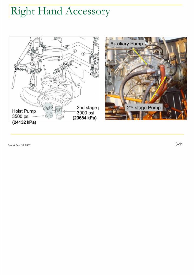
Right Hand Accessory
The right hand accessory provides a location for
additional hydraulic pumps to operate: 2nd stage pump,
Hoist pump and Auxiliary pump.
The 2nd stage hydraulic pump operates the primary flight
controls.
The hoist hydraulic pump pad operates additional
equipment such as the auxiliary pump or the hoist pump.
8/12/2019 3. Transmissions
http://slidepdf.com/reader/full/3-transmissions 8/523-11Rev. A Sept 18, 2007
Right Hand Accessory
Auxiliary Pump
2nd stage Pump
24132 kPa)20684 kPa)
8/12/2019 3. Transmissions
http://slidepdf.com/reader/full/3-transmissions 9/523-12Rev. A Sept 18, 2007
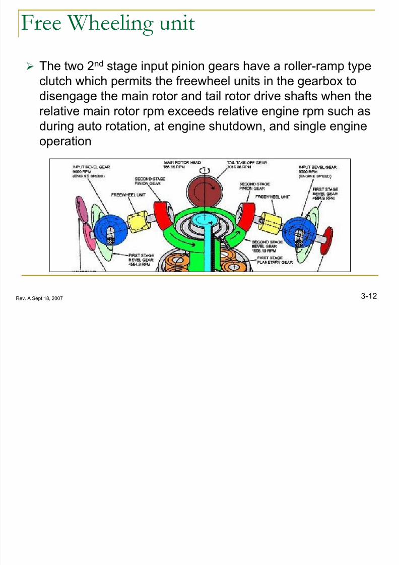
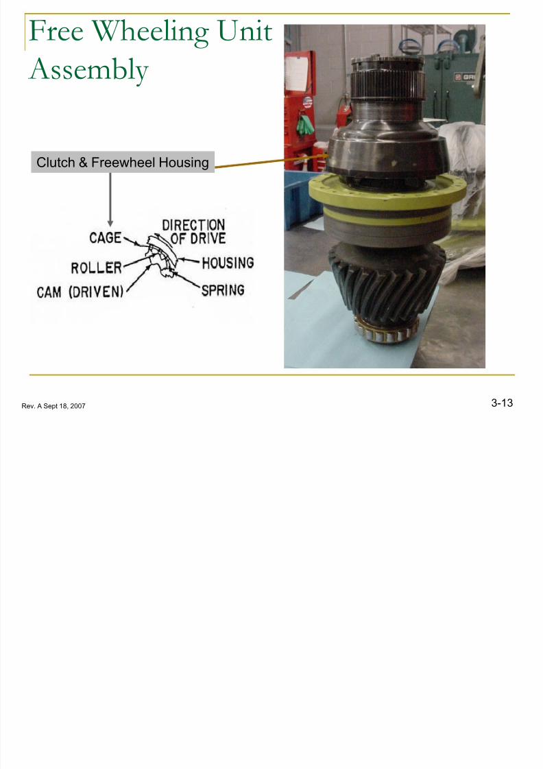
Free Wheeling unit
The two 2nd
stage input pinion gears have a roller-ramp typeclutch which permits the freewheel units in the gearbox to
disengage the main rotor and tail rotor drive shafts when the
relative main rotor rpm exceeds relative engine rpm such as
during auto rotation, at engine shutdown, and single engine
operation
8/12/2019 3. Transmissions
http://slidepdf.com/reader/full/3-transmissions 10/523-13Rev. A Sept 18, 2007
Free Wheeling Unit
Assembly
Clutch & Freewheel Housing

8/12/2019 3. Transmissions
http://slidepdf.com/reader/full/3-transmissions 11/523-14Rev. A Sept 18, 2007
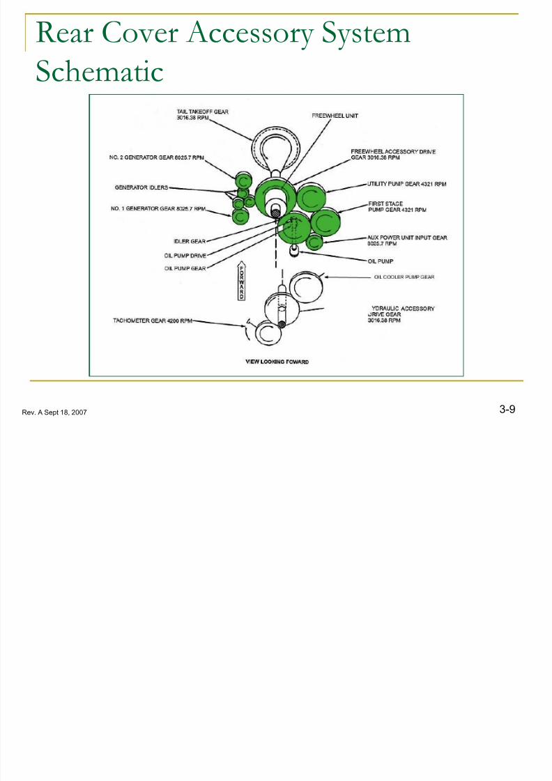
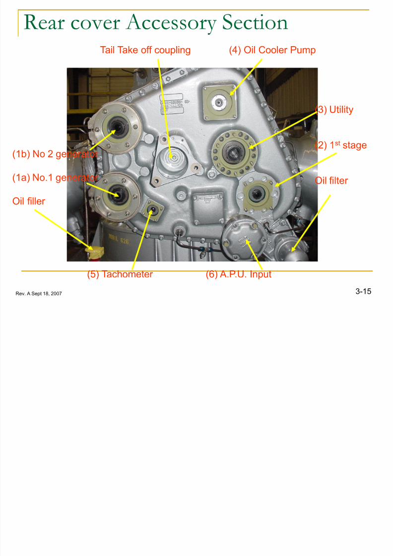
Accessory Section Rear cover
The main gearbox accessory
section is located on the rear of the
main gearbox.
Mounted on the rear cover are the:
1.Number 1 and number 2
electrical generators.2.The first stage hydraulic pump
3.The utility hydraulic pump
4.Oil Cooler pump
5.The tachometer Generator.6.The A.P.U. Drive gear.
8/12/2019 3. Transmissions
http://slidepdf.com/reader/full/3-transmissions 12/523-15Rev. A Sept 18, 2007
Rear cover Accessory Section
(1b) No 2 generator
(1a) No.1 generator
Oil filler
(5) Tachometer (6) A.P.U. Input
Tail Take off coupling (4) Oil Cooler Pump
(3) Utility
(2) 1st stage
Oil filter
8/12/2019 3. Transmissions
http://slidepdf.com/reader/full/3-transmissions 13/52
3-16Rev. A Sept 18, 2007
Rear Cover Accessory System
Schematic
8/12/2019 3. Transmissions
http://slidepdf.com/reader/full/3-transmissions 14/52
3-17Rev. A Sept 18, 2007
Accessory Drive Notes
Note: Tach. Generator (5), oil cooler pump (4), and the tail
take-off coupling will not be operating during A.P.P. operations.
Note: It is important to keep this operation to a minimum to
reduce the possibility of damage or failure of freewheel rollers.
8/12/2019 3. Transmissions
http://slidepdf.com/reader/full/3-transmissions 15/52
3-18Rev. A Sept 18, 2007
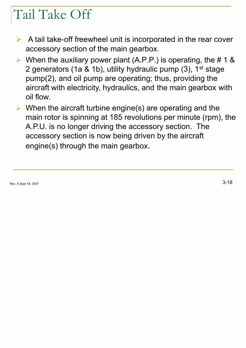
Tail Take Off
A tail take-off freewheel unit is incorporated in the rear coveraccessory section of the main gearbox.
When the auxiliary power plant (A.P.P.) is operating, the # 1 &
2 generators (1a & 1b), utility hydraulic pump (3), 1st stage
pump(2), and oil pump are operating; thus, providing the
aircraft with electricity, hydraulics, and the main gearbox withoil flow.
When the aircraft turbine engine(s) are operating and the
main rotor is spinning at 185 revolutions per minute (rpm), the
A.P.U. is no longer driving the accessory section. Theaccessory section is now being driven by the aircraft
engine(s) through the main gearbox.

8/12/2019 3. Transmissions
http://slidepdf.com/reader/full/3-transmissions 16/52
3-19Rev. A Sept 18, 2007
Tail Take-off
Assembly (T.T.O)
Free
Wheel
Gear
8/12/2019 3. Transmissions
http://slidepdf.com/reader/full/3-transmissions 17/52
3-20Rev. A Sept 18, 2007
APU Drive
Clutch
Drive Shaft

8/12/2019 3. Transmissions
http://slidepdf.com/reader/full/3-transmissions 18/52
3-21Rev. A Sept 18, 2007
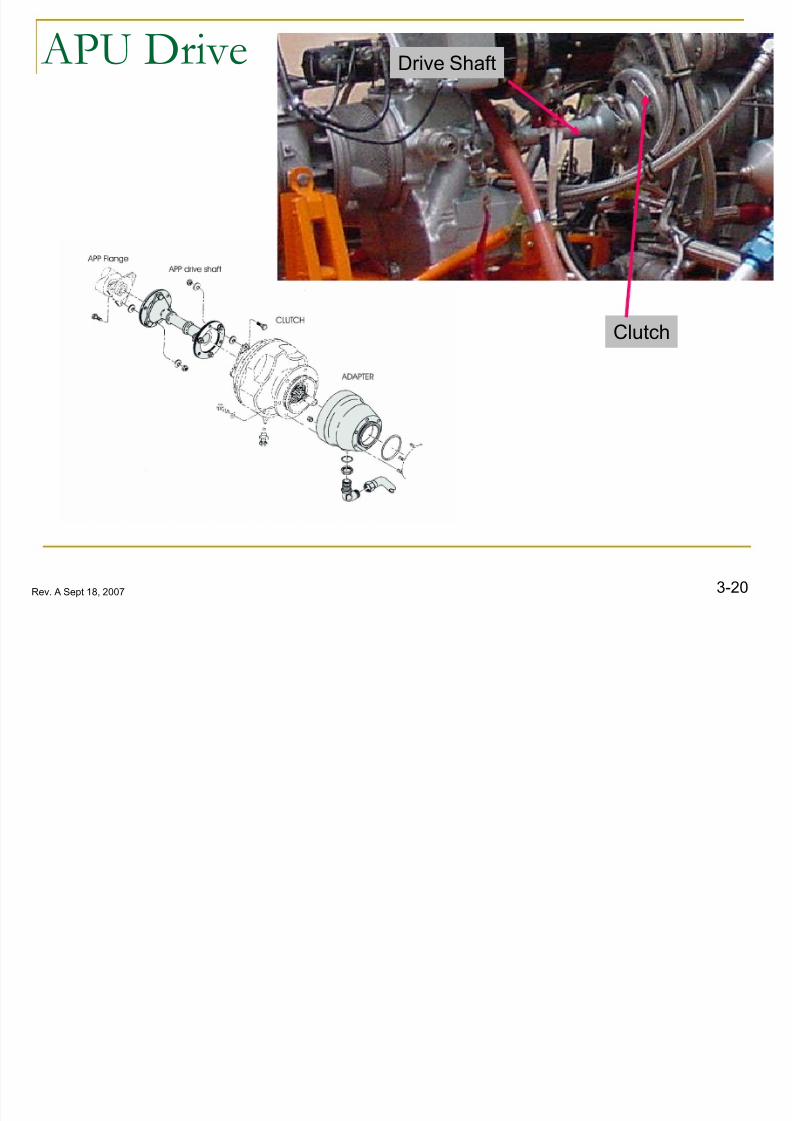
Auxiliary Power Unit
The Auxiliary Power Unit (A.P.U.) provides temporary powerfor the aircraft.
The A.P.U. drives the centrifugal type clutch assembly
mounted on the lower aft section of the rear cover.
The clutch couples the A.P.U. to the main gearbox by
engaging when the A.P.U. is operating at approximately 75%
and disengaging when the M/G/B speed (rpm) becomes
faster than that of the A.P.U.
The A.P.U. drives the accessory gear box at 8,000 rpm
The tail take off is driven at 8,025 rpm by the MGB.
8/12/2019 3. Transmissions
http://slidepdf.com/reader/full/3-transmissions 19/52
3-22Rev. A Sept 18, 2007
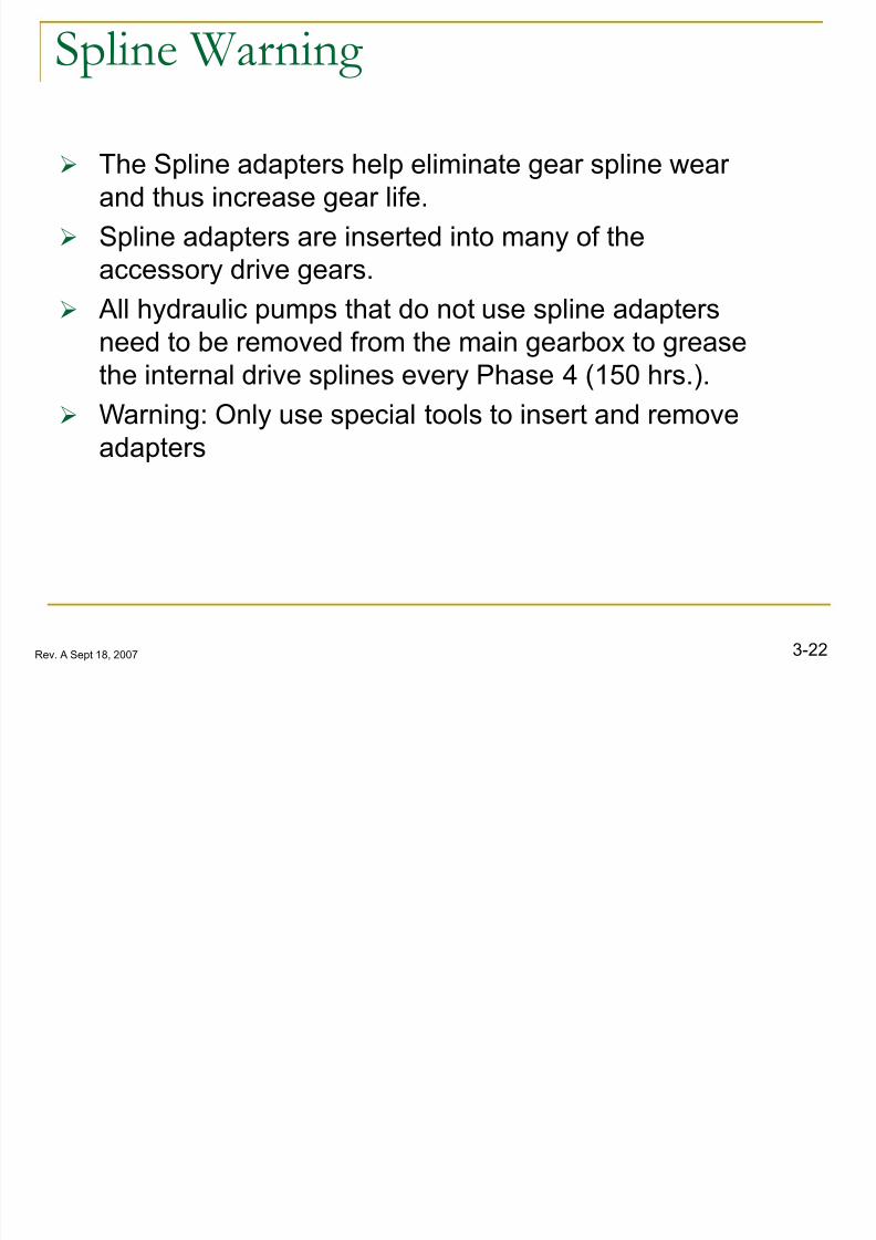
Spline Warning
The Spline adapters help eliminate gear spline wearand thus increase gear life.
Spline adapters are inserted into many of the
accessory drive gears.
All hydraulic pumps that do not use spline adaptersneed to be removed from the main gearbox to grease
the internal drive splines every Phase 4 (150 hrs.).
Warning: Only use special tools to insert and remove
adapters

8/12/2019 3. Transmissions
http://slidepdf.com/reader/full/3-transmissions 20/52
3-23Rev. A Sept 18, 2007
Spline adapter pictures
The spline adapters
(vespals) are made from
phenolic plastic.
8/12/2019 3. Transmissions
http://slidepdf.com/reader/full/3-transmissions 21/52
3-24Rev. A Sept 18, 2007
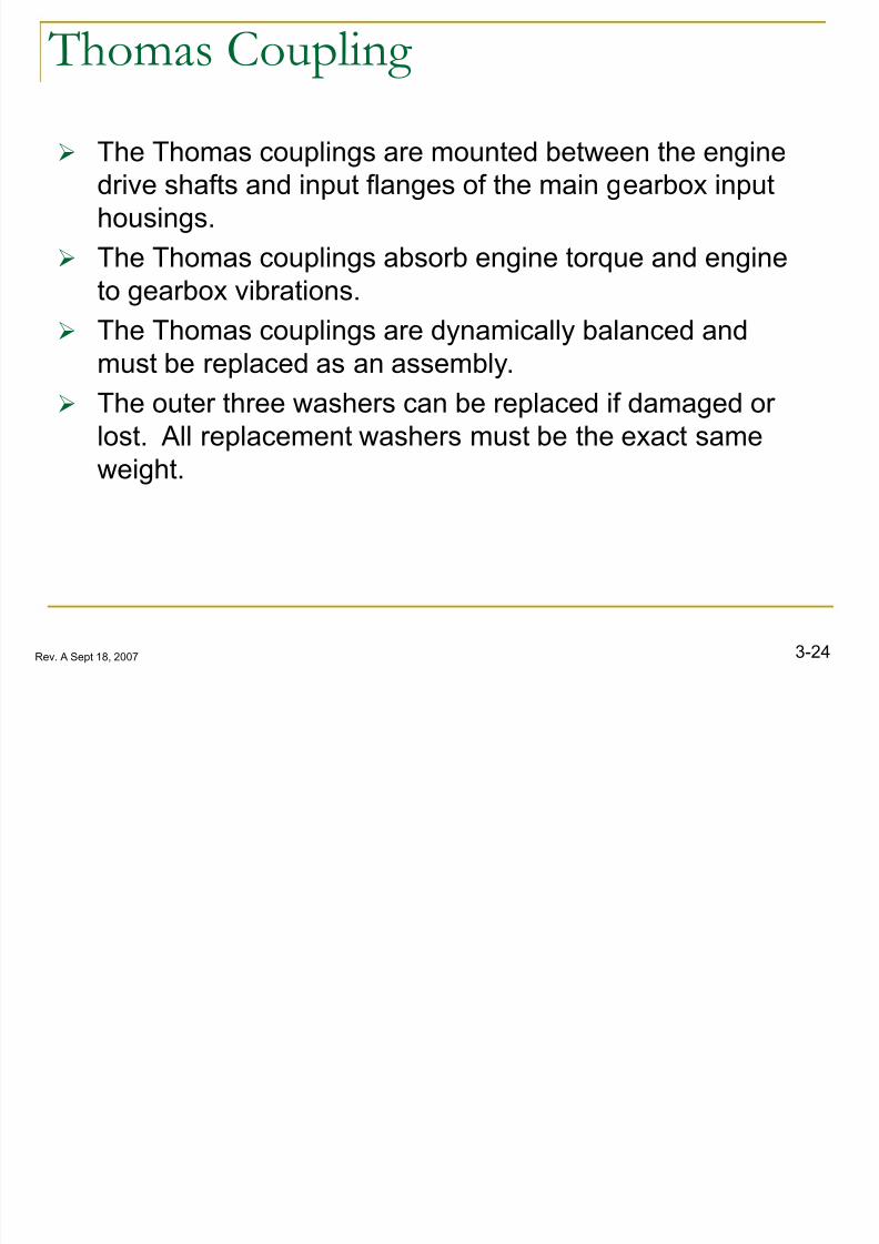
Thomas Coupling
The Thomas couplings are mounted between the enginedrive shafts and input flanges of the main gearbox input
housings.
The Thomas couplings absorb engine torque and engine
to gearbox vibrations.
The Thomas couplings are dynamically balanced and
must be replaced as an assembly.
The outer three washers can be replaced if damaged or
lost. All replacement washers must be the exact same
weight.
8/12/2019 3. Transmissions
http://slidepdf.com/reader/full/3-transmissions 22/52
3-25Rev. A Sept 18, 2007
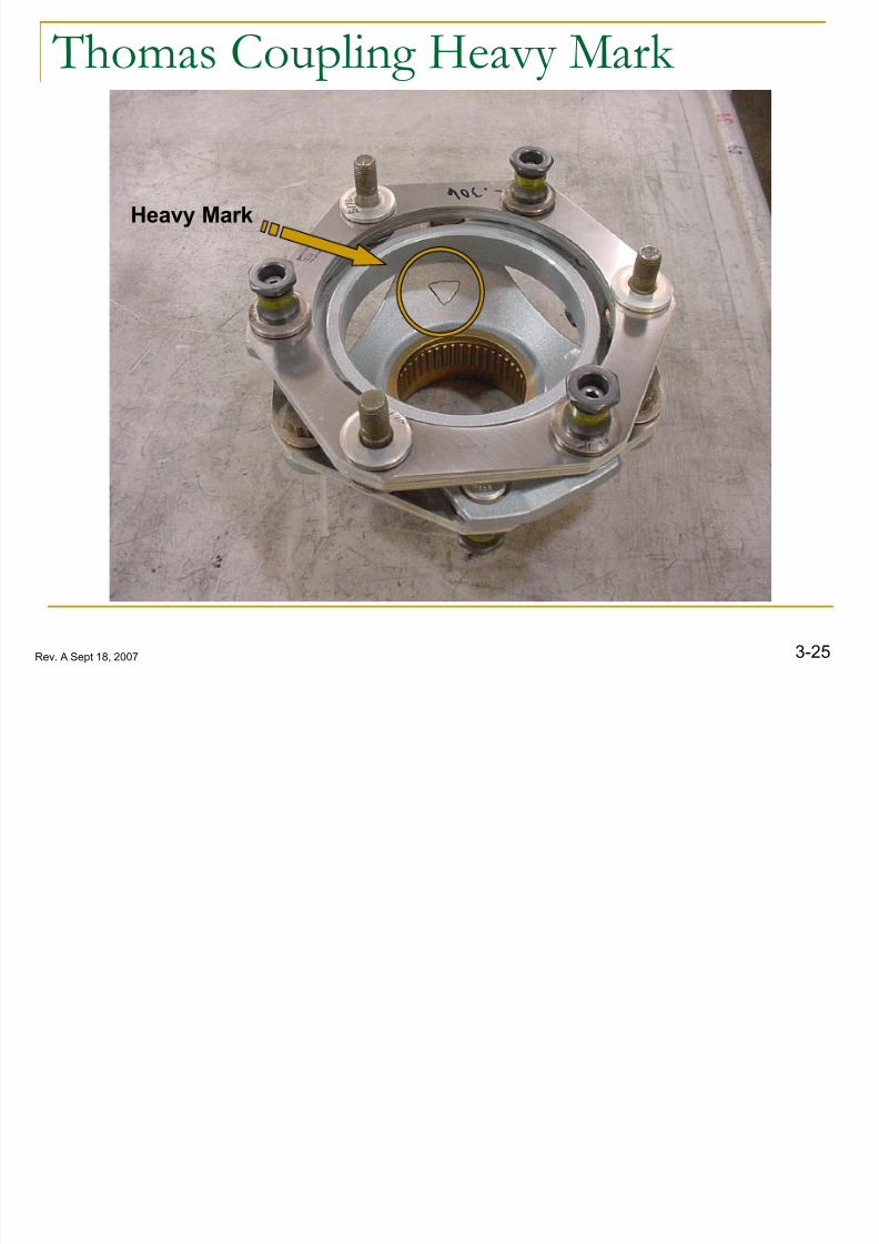
Thomas Coupling Heavy Mark
Heavy Mark

8/12/2019 3. Transmissions
http://slidepdf.com/reader/full/3-transmissions 23/52
3-26Rev. A Sept 18, 2007
Thomas Coupling notes
Any damage to the disks or other components of thecoupling may cause excessive vibration and the coupling
must be replaced.
When replacing Thomas Coupling input flange use anti-
seize on splines
Thomas couplings and engine high-speed shafts will be
identified with a residual heavy mark.
It is important to remember to off set these marks 180
degrees (Or as close to 180º as possible.)

8/12/2019 3. Transmissions
http://slidepdf.com/reader/full/3-transmissions 24/52
3-27Rev. A Sept 18, 2007
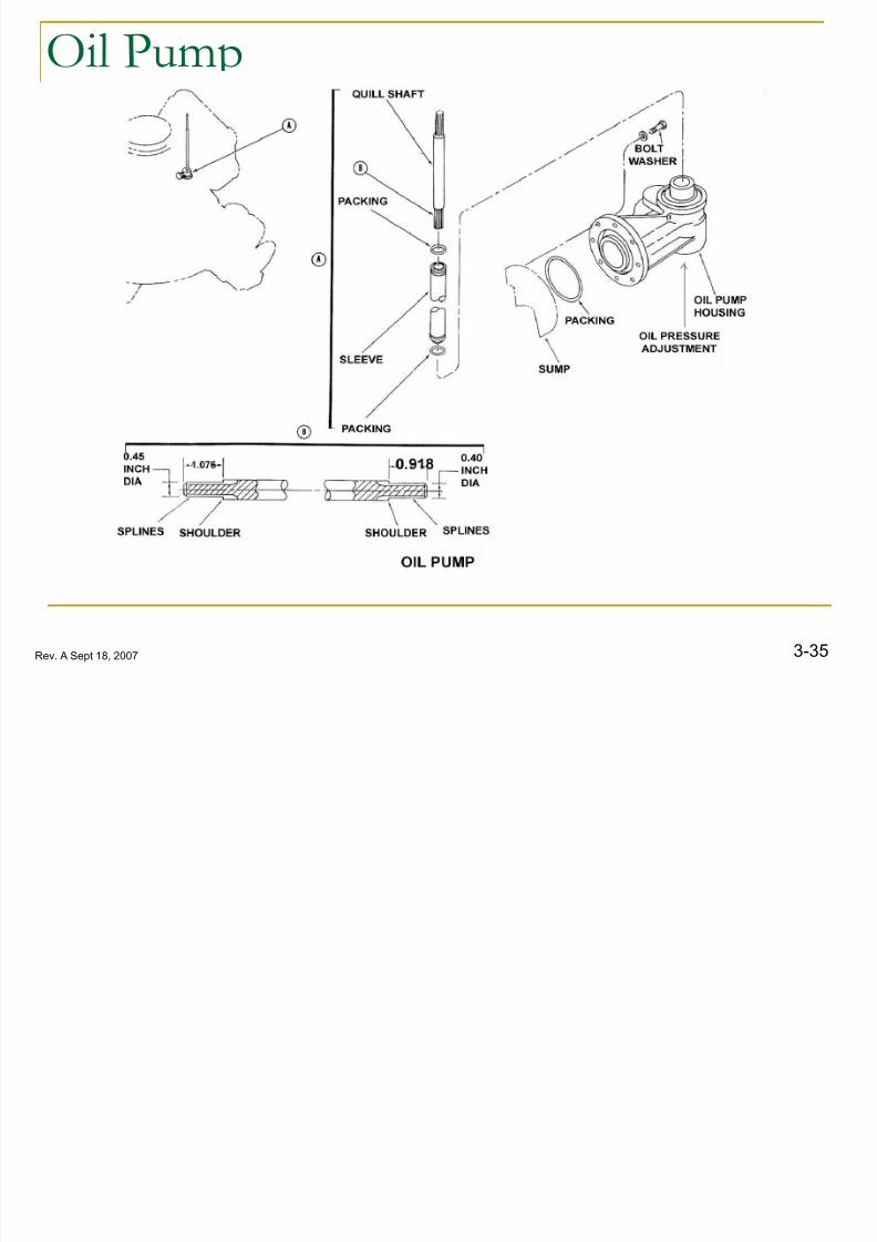
MGB Lubrication Description
Lubrication is accomplished by a self-priming wet sump
system.
The oil pump, attached to the main gearbox sump,
circulates oil for main gearbox lubrication and cooling.

8/12/2019 3. Transmissions
http://slidepdf.com/reader/full/3-transmissions 25/52
3-28Rev. A Sept 18, 2007
F-Gear Box Lubrication Schematic
8/12/2019 3. Transmissions
http://slidepdf.com/reader/full/3-transmissions 26/52
8/12/2019 3. Transmissions
http://slidepdf.com/reader/full/3-transmissions 27/52
3-30Rev. A Sept 18, 2007
Oil Filter
The oil filter consists of a cover, bowl, bypass valve, andcartridge with filter elements. Filter elements can be
bronze mesh or Monel mesh. Both are 40 micron nominal.
It is mounted on the lower right side of the main gearbox
accessory cover, and it filters all main gearbox oil betweenthe oil pump and oil cooler.
8/12/2019 3. Transmissions
http://slidepdf.com/reader/full/3-transmissions 28/52
3-31Rev. A Sept 18, 2007
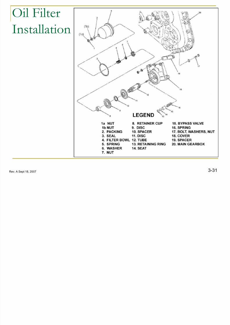
Oil Filter
Installation

8/12/2019 3. Transmissions
http://slidepdf.com/reader/full/3-transmissions 29/52
3-32Rev. A Sept 18, 2007
Oil Filter Bypass
If the filter becomes clogged, a bypass valve opens,allowing the oil to bypass the filter.
The oil cartridge should be removed, and the filter elements
should be cleaned and inspected every 150 hrs.
8/12/2019 3. Transmissions
http://slidepdf.com/reader/full/3-transmissions 30/52
3-33Rev. A Sept 18, 2007
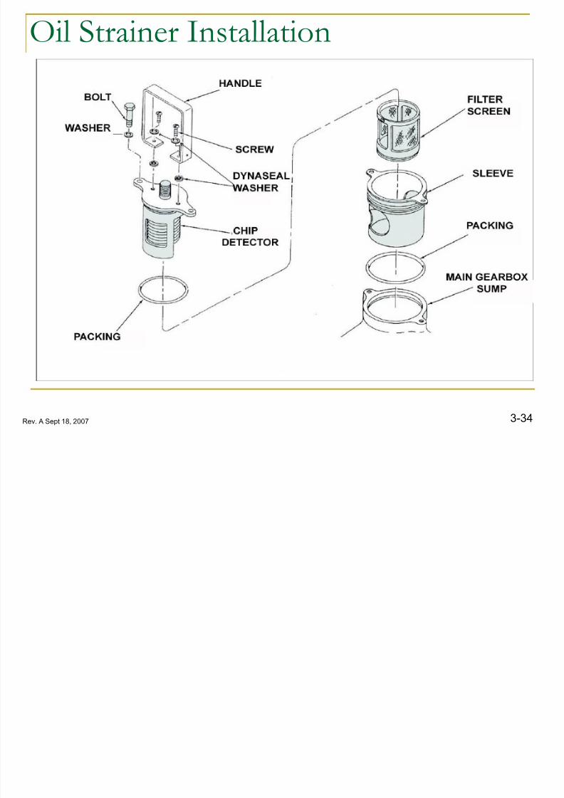
Oil strainer Description
A strainer in the lower part of the main gearbox consists of asleeve, retainer, and screen.
A chip detector is mounted inside the strainer. The strainer
prevents large particles from entering the pump and causing
damage.
The strainer may be removed and inspected without draining
the main gearbox by turning the outer sleeve 90º
Note: The Strainer should be removed, inspected, and
cleaned every 150 Hrs. with the oil filter.
8/12/2019 3. Transmissions
http://slidepdf.com/reader/full/3-transmissions 31/52
8/12/2019 3. Transmissions
http://slidepdf.com/reader/full/3-transmissions 32/52
3-35Rev. A Sept 18, 2007
Oil Pump
8/12/2019 3. Transmissions
http://slidepdf.com/reader/full/3-transmissions 33/52
3-36Rev. A Sept 18, 2007
Oil Pressure
Main Gear Box Oil is Mobil 626. The main gearbox oil pressure normal operating range is 50-
65 psi (345-448 kPa). The oil pressure is adjusted at the oil
pump which is located on the sump.
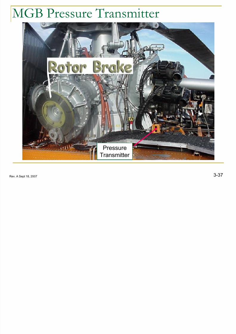
A pressure transmitter located on the aircraft transmissiondeck sends an electrical signal to the Pressure Indicator
located in the cockpit.
8/12/2019 3. Transmissions
http://slidepdf.com/reader/full/3-transmissions 34/52
3-37Rev. A Sept 18, 2007
MGB Pressure Transmitter
Pressure
Transmitter

8/12/2019 3. Transmissions
http://slidepdf.com/reader/full/3-transmissions 35/52
3-38Rev. A Sept 18, 2007
Oil Pressure Warning
When oil pressure at the furthest point from the pump dropsbelow 13-17 psi (90-117 kPa). the low oil warning switch on
the main gearbox actuates, causing the caution “trans oil
press” light to illuminate.
The switch is located on the lower front right side at the lowerMGB support.
8/12/2019 3. Transmissions
http://slidepdf.com/reader/full/3-transmissions 36/52
3-39Rev. A Sept 18, 2007
Oil Temperature
The main gearbox temperature indicating system consistsof an indicator, a resistance bulb located on the main
gearbox sump, just after the oil screen, and circuit
breakers.
The temperature resistance bulb converts the temperature
of the oil system to an electrical signal supplied to the
“trans oil temp” indicator at the center of the instrument
panel.
8/12/2019 3. Transmissions
http://slidepdf.com/reader/full/3-transmissions 37/52
3-40Rev. A Sept 18, 2007
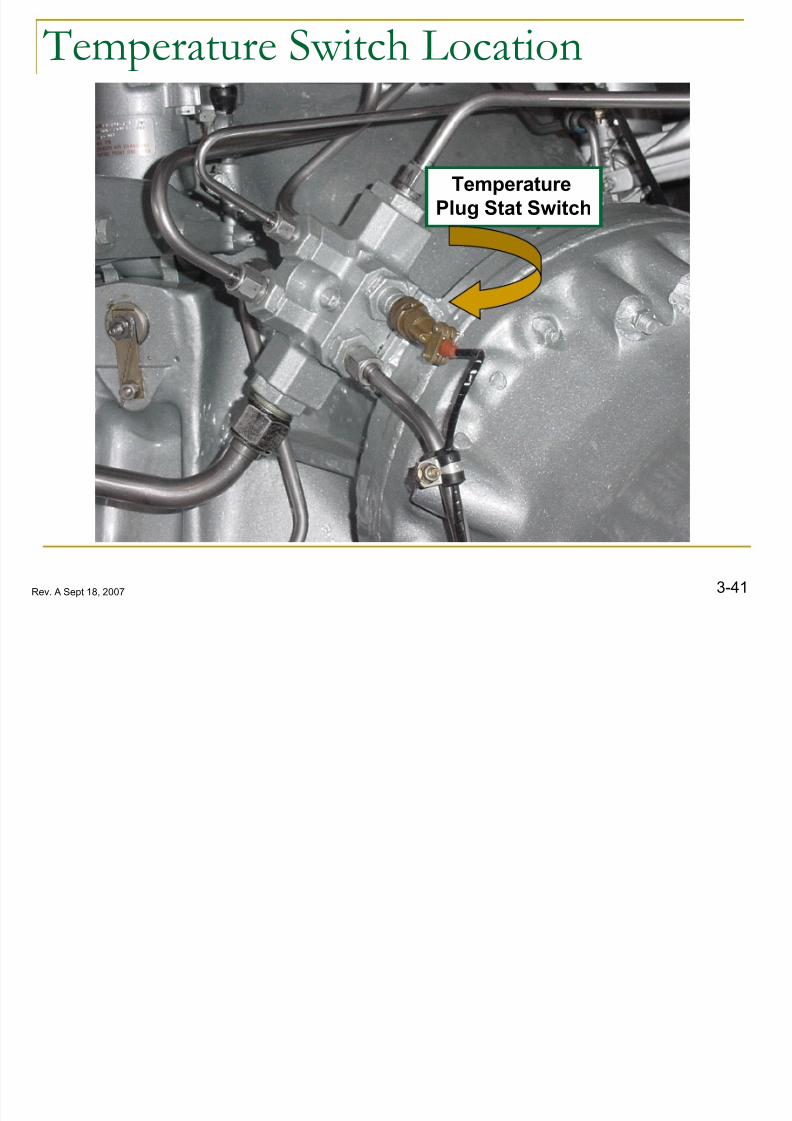
Hot Oil Warning
The main gearbox hot oil warning system consists of a
caution panel capsule, (Trans Oil Hot ), temperature Plug Stat
Switch, signal adapter unit, and a circuit breaker.
The temperature Plug Stat Switch is located in the secondary
manifold above the right hand input.
The Temperature Plug Stat Switch actuates when oiltemperature is over 121 ºC illuminating the caution-advisory
panel “Trans Oil Hot” light.
When the oil temperature drops below 121ºC the light will go
off.
8/12/2019 3. Transmissions
http://slidepdf.com/reader/full/3-transmissions 38/52
8/12/2019 3. Transmissions
http://slidepdf.com/reader/full/3-transmissions 39/52
3-42Rev. A Sept 18, 2007
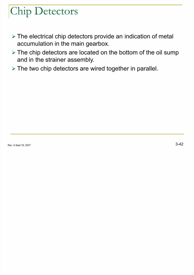
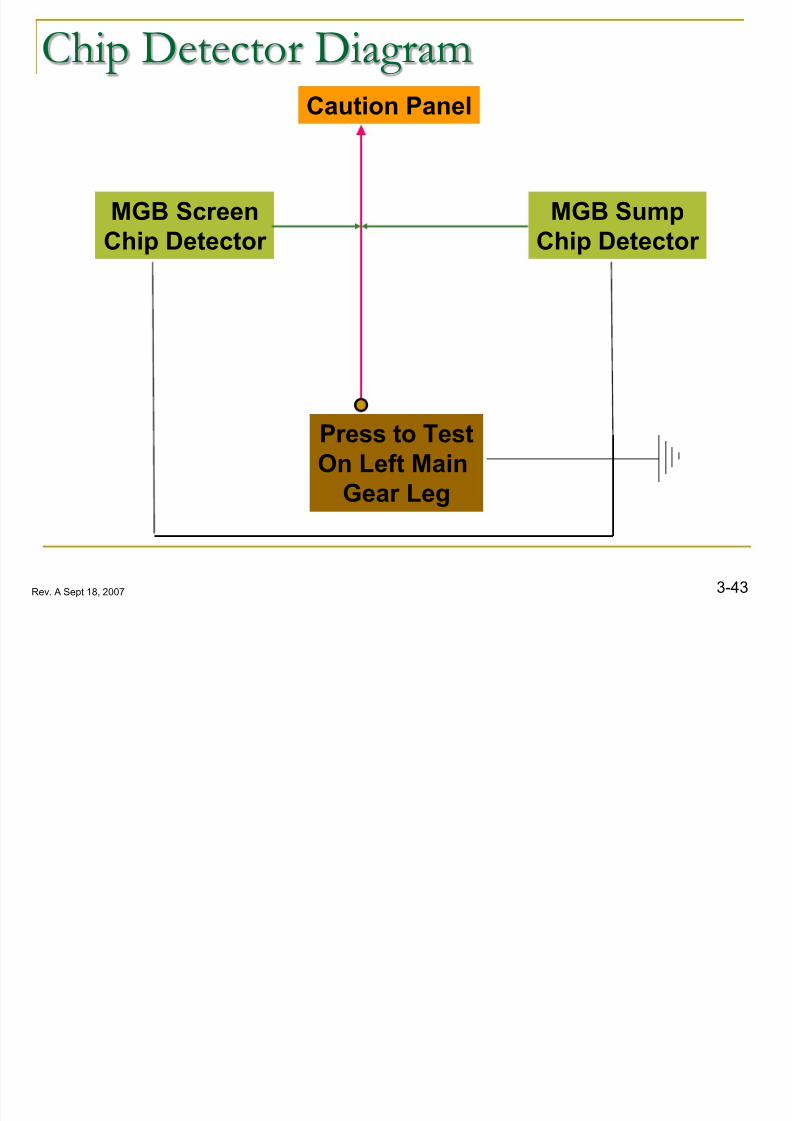
Chip Detectors
The electrical chip detectors provide an indication of metalaccumulation in the main gearbox.
The chip detectors are located on the bottom of the oil sump
and in the strainer assembly.
The two chip detectors are wired together in parallel.
8/12/2019 3. Transmissions
http://slidepdf.com/reader/full/3-transmissions 40/52
3-43Rev. A Sept 18, 2007
Chip Detector Diagram
MGB Sump
Chip Detector
MGB Screen
Chip Detector
Caution Panel
Press to Test
On Left Main
Gear Leg
il S Chi D
8/12/2019 3. Transmissions
http://slidepdf.com/reader/full/3-transmissions 41/52
3-44Rev. A Sept 18, 2007
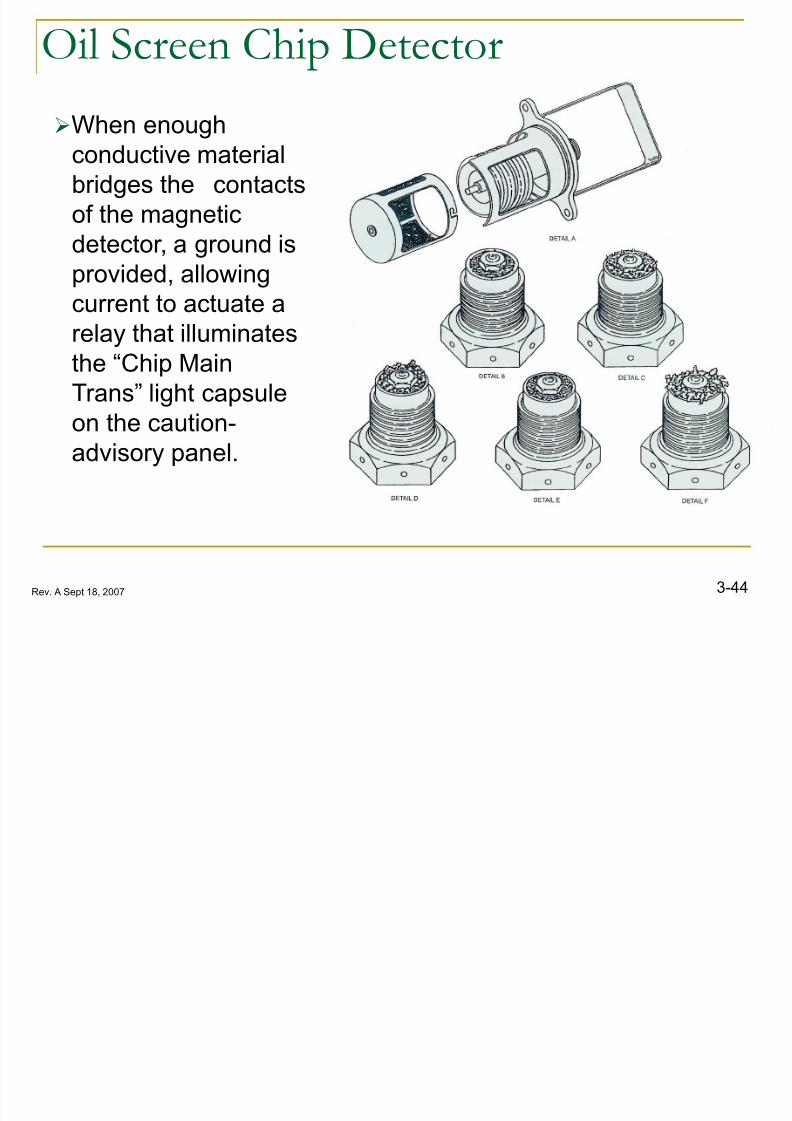
Oil Screen Chip Detector
When enough
conductive material
bridges the contacts
of the magnetic
detector, a ground is
provided, allowingcurrent to actuate a
relay that illuminates
the “Chip Main
Trans” light capsule
on the caution- advisory panel.
8/12/2019 3. Transmissions
http://slidepdf.com/reader/full/3-transmissions 42/52
l C l
8/12/2019 3. Transmissions
http://slidepdf.com/reader/full/3-transmissions 43/52
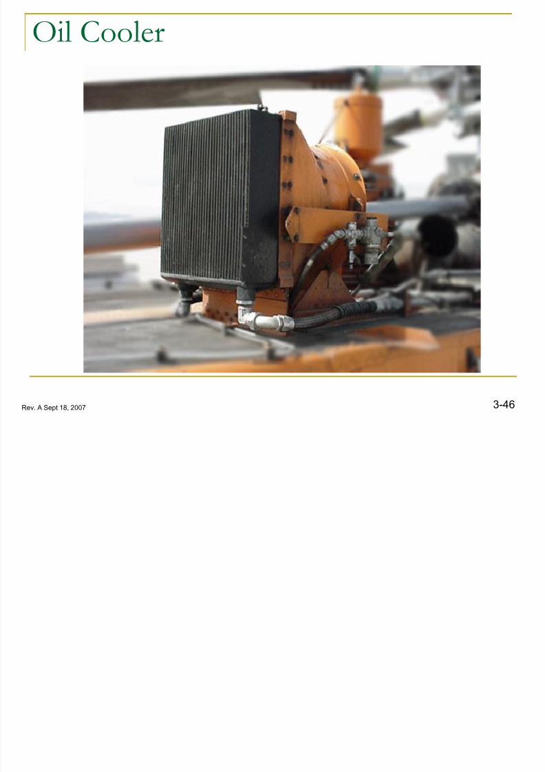
3-46Rev. A Sept 18, 2007
Oil Cooler
Oil C l
8/12/2019 3. Transmissions
http://slidepdf.com/reader/full/3-transmissions 44/52
3-47Rev. A Sept 18, 2007
Oil Cooler The oil cooler has a thermostatic bypass valve, which will
cause the oil to flow into the radiator core when the oil
temperature exceeds 70C.
Also, oil will bypass the core if pressure exceeds 50 psi
(345 kPa) differential. Note: Oil cooler assembly must be removed with the main
gearbox if the M/G/B is removed for making metal.
MGB I
8/12/2019 3. Transmissions
http://slidepdf.com/reader/full/3-transmissions 45/52
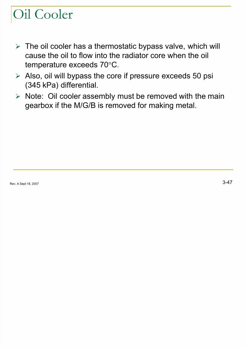
3-48Rev. A Sept 18, 2007
MGB Input
I S l R l

8/12/2019 3. Transmissions
http://slidepdf.com/reader/full/3-transmissions 46/52
3-49Rev. A Sept 18, 2007
Input Seal Replacement
R B k
8/12/2019 3. Transmissions
http://slidepdf.com/reader/full/3-transmissions 47/52
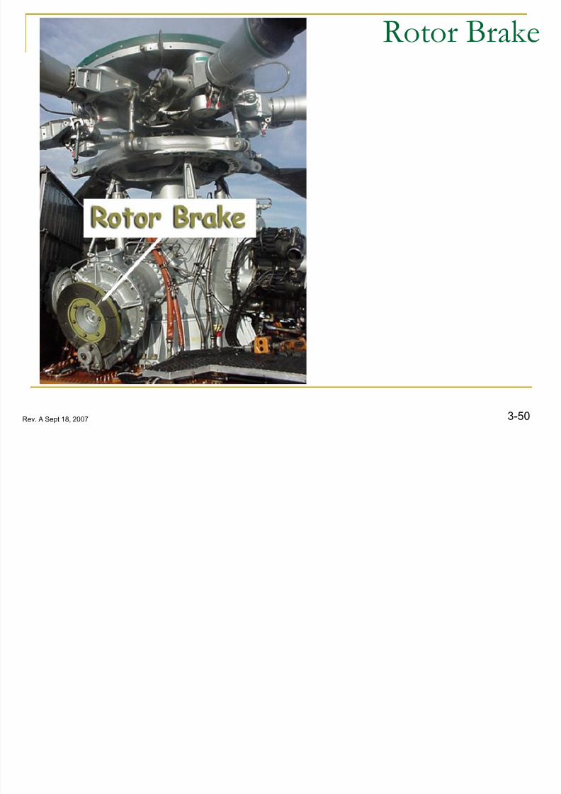
3-50Rev. A Sept 18, 2007
Rotor Brake

8/12/2019 3. Transmissions
http://slidepdf.com/reader/full/3-transmissions 48/52
R B k
8/12/2019 3. Transmissions
http://slidepdf.com/reader/full/3-transmissions 49/52
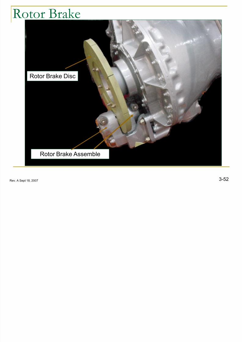
3-52Rev. A Sept 18, 2007
Rotor Brake
Rotor Brake Assemble
Rotor Brake Disc
R B k
8/12/2019 3. Transmissions
http://slidepdf.com/reader/full/3-transmissions 50/52
3-53Rev. A Sept 18, 2007
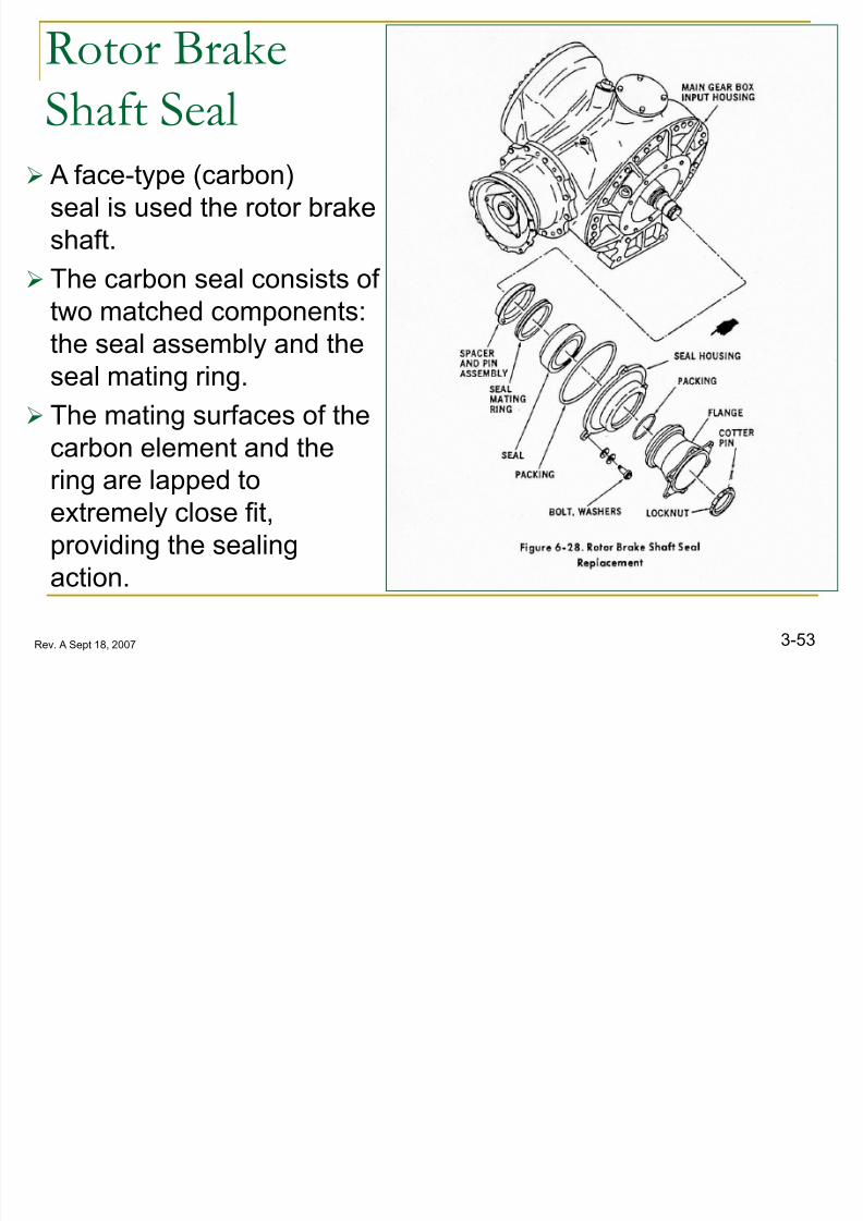
Rotor Brake
Shaft Seal
A face-type (carbon)
seal is used the rotor brake
shaft.
The carbon seal consists of
two matched components:the seal assembly and the
seal mating ring.
The mating surfaces of the
carbon element and thering are lapped to
extremely close fit,
providing the sealing
action.
MGB O ti l Ch k
8/12/2019 3. Transmissions
http://slidepdf.com/reader/full/3-transmissions 51/52
3-54Rev. A Sept 18, 2007
MGB Operational Check
New, overhauled or repaired main gearboxes receive a fullload run-in at the factory and require no further break-in run.
However, an operational check is required in addition to the
pilot pre-flight check to ensure proper installation and that
the lubrication system is working properly.
8/12/2019 3. Transmissions
http://slidepdf.com/reader/full/3-transmissions 52/52