Embed Size (px)
Citation preview
International Journal of Electrical Engineering and Technology (IJEET), ISSN 0976 – 6545(Print),
ISSN 0976 – 6553(Online) Volume 6, Issue 4, April (2015), pp. 16-29 © IAEME
16
POWER SYSTEM STABILIZER USING FUZZY LOGIC
CONTROLLER
Falguni S. Parmar
P.G. Student, Electrical Engineering Department,
U.V.P.C.E, Mehsana, Ganpat University, Gujarat, India
KirtiKumar M. Patel
Assistant Professor, Electrical Engineering Department,
U.V.P .C.E, Mehsana,Ganpat University, Gujarat, India
ABSTRACT
Power system stabilizers are used to enhance the damping during low frequency oscillations.
The paper presents a study of power system stabilizer using fuzzy logic to enhance stability of single
machine infinite bus system. The power system stabilizer is developed by using the conventional and
non-conventional controller. In the conventional controller a phase lead compensation technique is
used and in non-conventional controller fuzzy set theory is used. The proposed power system
stabilizer is designed for a single machine connected to an infinite bus power system. Speed
deviation and acceleration of synchronous machine are taken as the input signals to the fuzzy
controller and then the performance of conventional power system stabilizer (CPSS) and fuzzy logic
based power system stabilizer (FLPSS) are compared. Result presented in the paper demonstrate that
the fuzzy logic based power system stabilizer (FLPSS) design gives better performance than the
conventional power system stabilizer.
Keywords: LFOs, SMIB, Power System Stabilizer (PSS), Fuzzy Logic Controller (FLC)
I. INTRODUCTION
Power systems are subjected to low frequency disturbance that might cause loss of
synchronism and an eventual break down of entire system. The oscillations, which are typically in
the frequency range of 0.2 to 3.0 Hz, might be excited by the disturbance in the system or in some
cases might even build up spontaneously. These low frequency oscillations (LFOs) are generator
rotor angle oscillation which limit the power transmission capability of a network and sometimes
INTERNATIONAL JOURNAL OF ELECTRICAL ENGINEERING &
TECHNOLOGY (IJEET)
ISSN 0976 – 6545(Print) ISSN 0976 – 6553(Online) Volume 6, Issue 4, April (2015), pp. 16-29
© IAEME: www.iaeme.com/IJEET.asp Journal Impact Factor (2015): 7.7385 (Calculated by GISI)
www.jifactor.com
IJEET
© I A E M E

International Journal of Electrical Engineering and Technology
ISSN 0976 – 6553(Online) Volume 6, Issue 4, April (2015), pp.
even cause a loss of synchronism and an eventual break down of the entire system. For this purpose,
power system stabilizers (PSS) are used to generate supplementary contr
systemin order to damp out these low freq
system stabilizer (CPSS) have been widely accepted by the power utilities due to their simplicity,
more over they are the most cost e
become very common in operation of la
classic control techniques such as root
paper the CPSS use phase compensation where gain setting is design for specific operating
condition, CPSS giving poor performance under different operating condition. The constant
changing nature of power system makes the design of CPSS
difficult to design a stabilizer that could present good performance in all operation points of power
system. To overcome the drawback of CPSS
solution. Using fuzzy logic based techni
performance under different operation conditions. Fuzzy logic has the feature of simple concept,
easy implementation and computationally efficient. The fuzzy logic based power system stabilizer
model is evaluated on single machine infinite bus power system and then
performed between the conventional power system stabilizer (CPSS) and fuzzy logic based power
system stabilizer (FLPSS). Result presented in the paper clearly demonstrates
fuzzy logic based power system stabilizer (FLPSS) in comparison to the conventional power system
stabilizer (CPSS).
2. SYNCHRONOUS MACHINE MODEL
The performance of a synchronous machine connected to a large system through transmissi
lines. A general system configuration is shown in fig 1. The general system configuration of
synchronous machine connected to infinite bus through transmission network can be represented as
the Thevenin’s equivalent circuit where Et is terminal voltage,
Fig.1
International Journal of Electrical Engineering and Technology (IJEET), ISSN 0976
6553(Online) Volume 6, Issue 4, April (2015), pp. 16-29 © IAEME
17
even cause a loss of synchronism and an eventual break down of the entire system. For this purpose,
(PSS) are used to generate supplementary control signals for the excitation
systemin order to damp out these low frequency power system oscillations.
) have been widely accepted by the power utilities due to their simplicity,
more over they are the most cost effective damping control. The use of power system stabilizer has
become very common in operation of large electric power systems. CPSS
classic control techniques such as root-locus, phase compensation, eigen value analysis etc. In thi
paper the CPSS use phase compensation where gain setting is design for specific operating
condition, CPSS giving poor performance under different operating condition. The constant
tem makes the design of CPSS a difficult task.
difficult to design a stabilizer that could present good performance in all operation points of power
To overcome the drawback of CPSS, fuzzy logic based technique has been suggested as
solution. Using fuzzy logic based technique, mathematic model can be avoided,
performance under different operation conditions. Fuzzy logic has the feature of simple concept,
easy implementation and computationally efficient. The fuzzy logic based power system stabilizer
s evaluated on single machine infinite bus power system and then
performed between the conventional power system stabilizer (CPSS) and fuzzy logic based power
Result presented in the paper clearly demonstrates
logic based power system stabilizer (FLPSS) in comparison to the conventional power system
SYNCHRONOUS MACHINE MODEL
The performance of a synchronous machine connected to a large system through transmissi
lines. A general system configuration is shown in fig 1. The general system configuration of
synchronous machine connected to infinite bus through transmission network can be represented as
the Thevenin’s equivalent circuit where Et is terminal voltage, Eb is bus voltage.
Fig.1 General Configuration of system
Fig.2 Equivalent system
(IJEET), ISSN 0976 – 6545(Print),
© IAEME
even cause a loss of synchronism and an eventual break down of the entire system. For this purpose,
ol signals for the excitation
s. Conventional power
) have been widely accepted by the power utilities due to their simplicity,
ffective damping control. The use of power system stabilizer has
can be designed using
, eigen value analysis etc. In this
paper the CPSS use phase compensation where gain setting is design for specific operating
condition, CPSS giving poor performance under different operating condition. The constant
a difficult task. Therefore it is very
difficult to design a stabilizer that could present good performance in all operation points of power
, fuzzy logic based technique has been suggested as
mathematic model can be avoided, while giving good
performance under different operation conditions. Fuzzy logic has the feature of simple concept,
easy implementation and computationally efficient. The fuzzy logic based power system stabilizer
s evaluated on single machine infinite bus power system and then comparison studies
performed between the conventional power system stabilizer (CPSS) and fuzzy logic based power
Result presented in the paper clearly demonstrates that the superiority of
logic based power system stabilizer (FLPSS) in comparison to the conventional power system
The performance of a synchronous machine connected to a large system through transmission
lines. A general system configuration is shown in fig 1. The general system configuration of
synchronous machine connected to infinite bus through transmission network can be represented as
Eb is bus voltage.
International Journal of Electrical Engineering and Technology (IJEET), ISSN 0976 – 6545(Print),
ISSN 0976 – 6553(Online) Volume 6, Issue 4, April (2015), pp. 16-29 © IAEME
18
The equations governing the synchronous machine model are:
Per unit stator voltage equation
e� = p ᴪ� − ᴪ�ω� − Ri� (1)
e� = p ᴪ� − ᴪ�ω� − Ri� (2)
Per unit rotor voltage equatin:
e�� = p ᴪ�� − R��i�� (3)
0= p ᴪ�� + R��i�� (4)
0= p ᴪ�� + R��i��
Per unit stator flux linkage equation:
ᴪ� = − �L� + L��i� + L�i�� + L�i�� (5)
ᴪ� = − �L� + L��i� + L�i�� + L�i�� (6)
Per unit rotor flux linkage equation:
ᴪ�� = L���i�� + L���i�� − L�i� (7)
ᴪ�� = L���i�� + L�i�� − L�i� (8)
Per air gap-torque equation:
T� = ᴪ�i� − ᴪ�i� (9)
Motion equations: ��
�� = ω − ω� (10)
�� ��
= ��
���T� − T�� (11)
3. POWER SYSTEM STABILIZER
The basic function of power system stabilizer is to add damping electro mechanical
oscillation for generator excitation system in order to damp low frequency power oscillation. CPSS
essentially use the power amplification capability of generator to generate a damping torque in phase
with the speed change of the generator rotor. This is achieved by injecting a stabilizing signal into
the excitation system voltage reference in such a way that a component of electrical torque
proportional to the rotor speed is produce.
The CPSS can use various inputs, such as the speed deviation of the generator shaft, the
change in electrical power or accelerating power or even the terminal bus frequency. In this paper
speed deviation ωr is used as input in CPSS and output of any CPSS is voltage signal and it is
present only when a rotor is oscillation or there is oscillation in the system.
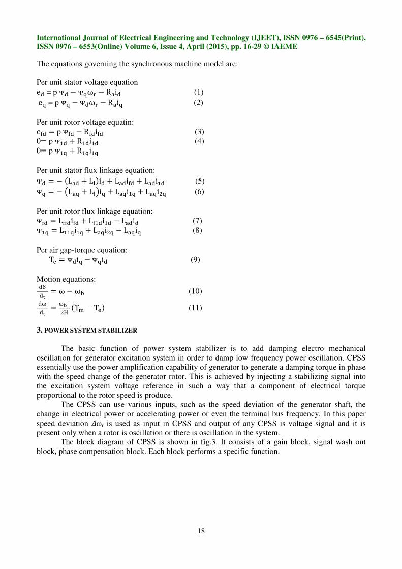
The block diagram of CPSS is shown in fig.3. It consists of a gain block, signal wash out
block, phase compensation block. Each block performs a specific function.
International Journal of Electrical Engineering and Technology (IJEET), ISSN 0976 – 6545(Print),
ISSN 0976 – 6553(Online) Volume 6, Issue 4, April (2015), pp. 16-29 © IAEME
19
Signal Phase
Gain washout compensation
!"
Fig.3: Block diagram of CPSS
1). Gain block
The stabilizer gain KSTAB determines the amount of damping introduced by the CPSS. Ideally
the gain should be set at a value corresponding to maximum damping. However it is often limited by
other considerations.
2). Signal washout block
The signal washout block serves as high pass filter, with time constant Tw high enough to
allow signals associated with oscillations in wrto pass unchanged, which removes d.c signals.
Without it, steady changes in speed would modify the terminal voltage. It allow PSS to respond only
to changes in speed. The value of Tw is not critical and may be in the range of 1 to 20 seconds. The
main consideration is that it should be long enough to pass stabilizing signals at the frequencies of
interest unchanged, but not so long that it leads to undesirable generator voltage excursions during
system islanding conditions.
Fig.4 Design of washout block
The transfer function as shown in fig4 should be a high pass filter. Transfer functions gain
should be zero when the frequency of oscillation to be zero. If we put S=0 then this transfer function
provide zero gain then steady change in ωr. The CPSS should give zero output under steady state
condition. So adding this block in cascade with the other block of a CPS Sensure that the output is
zero in steady state. If there is a step change in u, the output of this block will be as shown in fig 4.
KSTAB # $%
1 + # $%
1 + # $�
1 + # $�
vs
International Journal of Electrical Engineering and Technology (IJEET), ISSN 0976 – 6545(Print),
ISSN 0976 – 6553(Online) Volume 6, Issue 4, April (2015), pp. 16-29 © IAEME
20
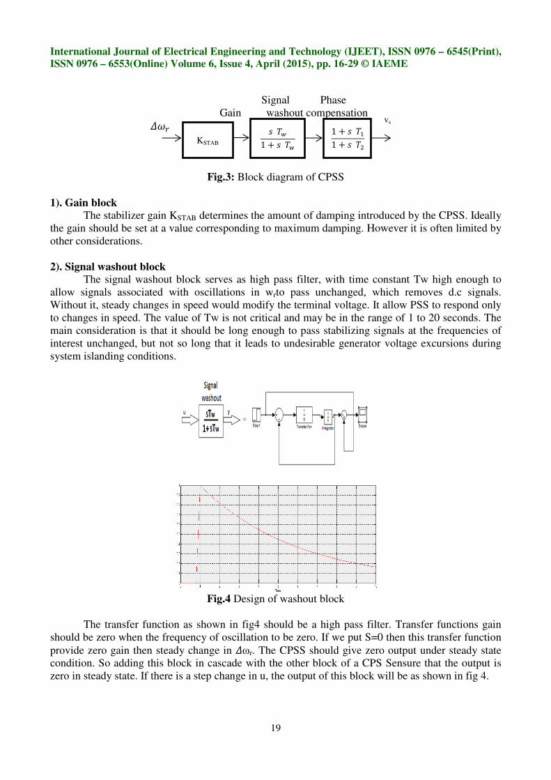
3). Phase Compensation Block
The phase compensation block provides the appropriate phase lead characteristic to
compensate for the phase lag between exciter input and generator electrical torque. The phase
compensation may be a single first order block as shown in fig.5. Or having more first order blocks
or second order blocks with complex roots. Basic function of this phase compensator is to provide
phase lead so normally it known as phase lead controller or phase lead compensator.
Fig.5: Design of phase compensator
If we choose T1 greater than T2 we can get a lead compensator and got a maximum phase lead
which is known as centre frequency fc.
fc= �
�'�
√)�∗)� (12)
By tuning T1 and T2 we can change the centre frequency.
4. FUZZY LOGIC CONTROLLER
Since the concept of fuzzy logic given by zadeh in 1965, it has found application in various
area including a controller for PSS. A fuzzy controller as shown in fig comprises of four stages:
fuzzification, a knowledge base, decision making, and defuzzification. The fuzzification interface
coverts input data into suitable linguistic values that can be viewed as label fuzzy sets. The
knowledge base comprises knowledge of application domain and attendant control goals by means of
set of linguistic control rules. The decision making is the aggregation of output of various control
rules that simulate the capability of human decision making. The defuzzification interface
performsscale mapping, which converts the range of values of output variables into corresponding
universe of discourse.

International Journal of Electrical Engineering and Technology (IJEET), ISSN 0976 – 6545(Print),
ISSN 0976 – 6553(Online) Volume 6, Issue 4, April (2015), pp. 16-29 © IAEME
21
Fig.6: The principle design of FLC
The fuzzy controller design consists of the following steps:
1. Identification of input and output variables.
2. Construction of control rules.
3. Establishing the approach for describing system in terms of fuzzy sets, i.e. establishing
fuzzification method and fuzzy membership functions.
4. Selection of the composition rule of inference.
5. Defuzzification method, i.e. transformation of the fuzzy control statement into specific control
actions.
5. DESIGN OF FUZZY LOGIC BASED PSS
The fuzzy controller used in PSS is normally a two input and a single output component. It is
usually a MISO system. The design of fuzzy logic based PSS shown in fig. The two inputs are
change in angular speed (speed deviation) and rate of change of angular speed (acceleration speed)
whereas output of fuzzy logic controller is a voltage signal (Vpss).
Fig.7: Design of fuzzy logic based PSS
Knowledge
base
Control system
(process)
Defuzzification
interface
Decision making
logic
Fuzzification
interface
International Journal of Electrical Engineering and Technology (IJEET), ISSN 0976 – 6545(Print),
ISSN 0976 – 6553(Online) Volume 6, Issue 4, April (2015), pp. 16-29 © IAEME
22
6. INPUT/OUTPUT VARIABLES
The design starts with assigning the mapped variable inputs/output of the fuzzy logic
controller (FLC). The first input variable to the FLC is the generator speed deviation and the second
is acceleration. The output variable to the FLC is the voltage. After choosing proper variables as
input and output of fuzzy controller, it is required to decide on the linguistic variables. These
variables transform the numeric values of the input of fuzzy controller to fuzzy quantities. The
number of linguistic variables describing the fuzzy subsets of a variable varies according to the
application. Here seven linguistic variables for each of the input and output variables are used to
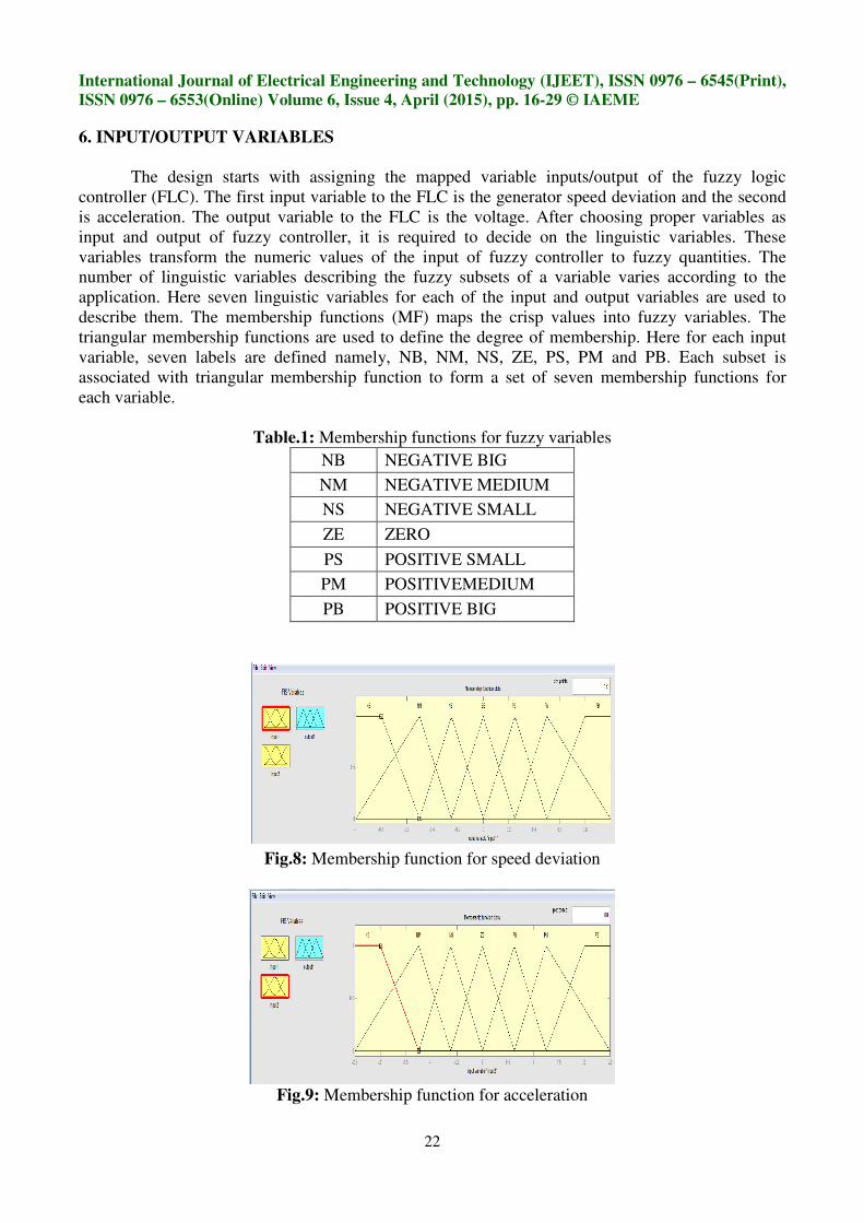
describe them. The membership functions (MF) maps the crisp values into fuzzy variables. The
triangular membership functions are used to define the degree of membership. Here for each input
variable, seven labels are defined namely, NB, NM, NS, ZE, PS, PM and PB. Each subset is
associated with triangular membership function to form a set of seven membership functions for
each variable.
Table.1: Membership functions for fuzzy variables
NB NEGATIVE BIG
NM NEGATIVE MEDIUM
NS NEGATIVE SMALL
ZE ZERO
PS POSITIVE SMALL
PM POSITIVEMEDIUM
PB POSITIVE BIG
Fig.8: Membership function for speed deviation
Fig.9: Membership function for acceleration

International Journal of Electrical Engineering and Technology (IJEET), ISSN 0976 – 6545(Print),
ISSN 0976 – 6553(Online) Volume 6, Issue 4, April (2015), pp. 16-29 © IAEME
23
Fig.10: Membership function for voltage Vpss
The membership function for speed deviation, acceleration and voltage are shown in fig
8,9,10 respectively. Knowledge base involves defining the rules represented as IF-THEN rules
statements governing the relationships between input and output variables in terms of membership
functions. In this stage the input variables speed deviation and acceleration are processed by the
inference engine that execute 7 × 7 rules represented in rule Table.2Each rule conjuncts speed
deviation( ω) and acceleration fuzzy set values. The knowledge required to generate the fuzzy rules
can be derived from offline simulation. Some knowledge can be based on the understanding of the
behaviour of the dynamic system under control. For monotonic systems, a symmetrical rule table is
very appropriate, although sometimes it may need slight adjustment based on the behaviour of the
specific system.If the system dynamics are not known are highly nonlinear, trial and error procedures
and experience play an important role in defining the rules.
Table.2: Decision table of 49 rules
Speed
Deviation
Acceleration
NB NM NS ZE PS PM PB
NB NB NB NB NB NM NS ZE
NM NB NB NM NM NS ZE PS
NS NB NM NS NS ZE PS PM
ZE NM NS ZE ZE PM PB PB
PS NM NS PS PM PM PB PB
PM NS ZE PS PM PM PB PB
PB ZE ZE PM PB PB PB PB
Decision table.2 shows the result of 49 rules, where a positive control signal is for the
deceleration control and a negative signal is for acceleration control. In the rules of a proposed
FLPSS, the input variables are connected by an ‘AND’ method.
International Journal of Electrical Engineering and Technology
ISSN 0976 – 6553(Online) Volume 6, Issue 4, April (2015), pp.
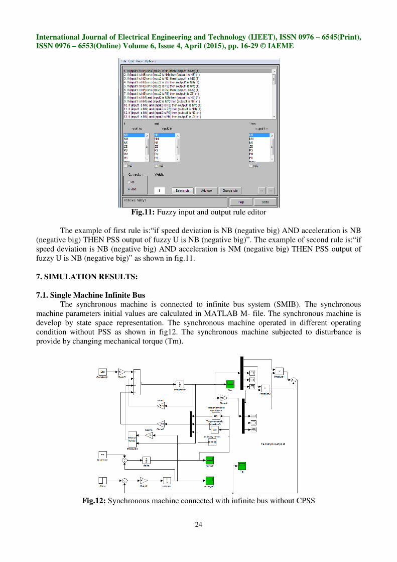
Fig.
The example of first rule is:“if
(negative big) THEN PSS output of fuzzy U is
speed deviation is NB (negative big) AND acceleration is NM (negative big) THEN PSS
fuzzy U is NB (negative big)” as shown in fig.11
7. SIMULATION RESULTS:
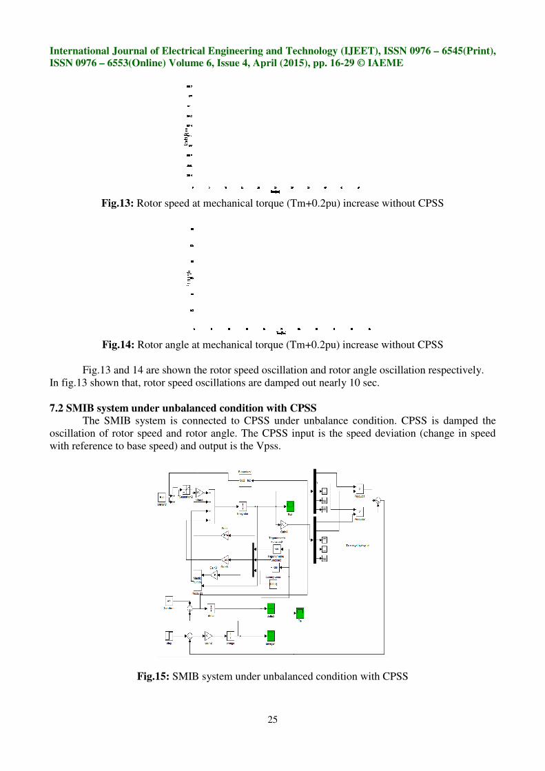
7.1. Single Machine Infinite Bus
The synchronous machine is connected t
machine parameters initial values are calculated in MATLAB M
develop by state space representation. The synchronous
condition without PSS as shown in fig12
provide by changing mechanical torque
Fig.12: Synchronous machine connected with infinite bus
International Journal of Electrical Engineering and Technology (IJEET), ISSN 0976
6553(Online) Volume 6, Issue 4, April (2015), pp. 16-29 © IAEME
24
.11: Fuzzy input and output rule editor
is:“if speed deviation is NB (negative big) AND acceleration is
negative big) THEN PSS output of fuzzy U is NB (negative big)”. The example of se
speed deviation is NB (negative big) AND acceleration is NM (negative big) THEN PSS
as shown in fig.11.
Single Machine Infinite Bus
The synchronous machine is connected to infinite bus system (SMIB). The synchronous
machine parameters initial values are calculated in MATLAB M- file. The synchronous machine is
develop by state space representation. The synchronous machine operated
as shown in fig12. The synchronous machine subjected to disturbance is
torque (Tm).
ynchronous machine connected with infinite bus without CPSS
(IJEET), ISSN 0976 – 6545(Print),
© IAEME
negative big) AND acceleration is NB
negative big)”. The example of second rule is:“if
speed deviation is NB (negative big) AND acceleration is NM (negative big) THEN PSS output of
o infinite bus system (SMIB). The synchronous
file. The synchronous machine is
in different operating
machine subjected to disturbance is
without CPSS
International Journal of Electrical Engineering and Technology
ISSN 0976 – 6553(Online) Volume 6, Issue 4, April (2015), pp.
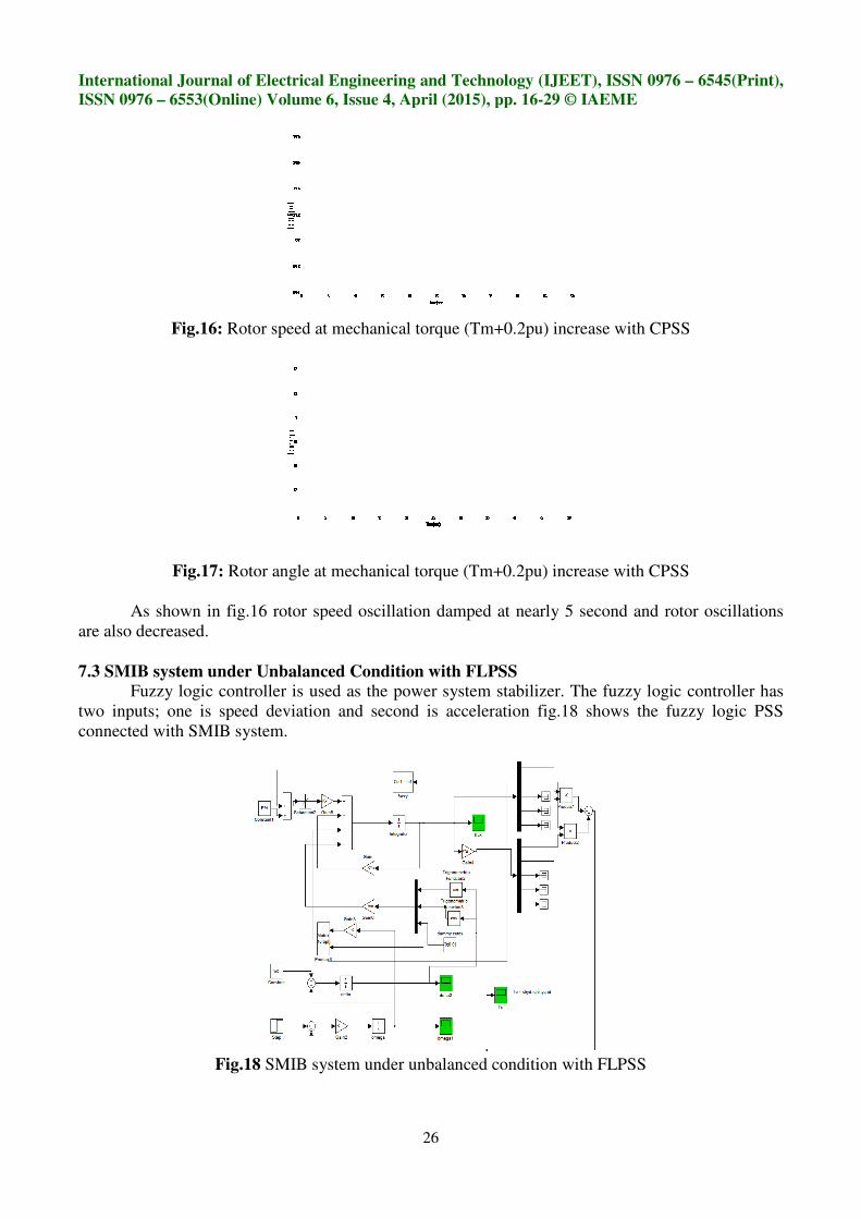
Fig.13: Rotor speed at mechanical torque (Tm+0.2pu) increase withou
Fig.14: Rotor angle at mechanical torque (Tm+0.2pu) increase without CPSS
Fig.13 and 14 are shown the rotor speed oscillation and rotor angle oscillation respectively.
In fig.13 shown that, rotor speed oscillations are
7.2 SMIB system under unbalanced condition with CPSS
The SMIB system is connected to CPSS under unbalance condition. CPSS is damped the
oscillation of rotor speed and rotor angle. The CPSS input is the speed deviation (change in speed
with reference to base speed) and output is the Vpss.
Fig.15: SMIB system under unbalanced condition with CPSS
International Journal of Electrical Engineering and Technology (IJEET), ISSN 0976
6553(Online) Volume 6, Issue 4, April (2015), pp. 16-29 © IAEME
25
otor speed at mechanical torque (Tm+0.2pu) increase withou
Rotor angle at mechanical torque (Tm+0.2pu) increase without CPSS
are shown the rotor speed oscillation and rotor angle oscillation respectively.
oscillations are damped out nearly 10 sec.
SMIB system under unbalanced condition with CPSS
The SMIB system is connected to CPSS under unbalance condition. CPSS is damped the
oscillation of rotor speed and rotor angle. The CPSS input is the speed deviation (change in speed
speed) and output is the Vpss.
SMIB system under unbalanced condition with CPSS
(IJEET), ISSN 0976 – 6545(Print),
© IAEME
otor speed at mechanical torque (Tm+0.2pu) increase without CPSS
Rotor angle at mechanical torque (Tm+0.2pu) increase without CPSS
are shown the rotor speed oscillation and rotor angle oscillation respectively.
The SMIB system is connected to CPSS under unbalance condition. CPSS is damped the
oscillation of rotor speed and rotor angle. The CPSS input is the speed deviation (change in speed
SMIB system under unbalanced condition with CPSS
International Journal of Electrical Engineering and Technology
ISSN 0976 – 6553(Online) Volume 6, Issue 4, April (2015), pp.
Fig.16: Rotor speed at mechanical torque
Fig.17: Rotor angle at mechanical torque (Tm+0.2pu) increase with CPSS
As shown in fig.16 rotor spee
are also decreased.
7.3 SMIB system under Unbalanced Condition with FLPSS
Fuzzy logic controller is used as the power system stabilizer. The fuzzy logic controller has
two inputs; one is speed deviation and second is acceleration fig
connected with SMIB system.
Fig.18 SMIB system under unbalanced condition with FLPSS
International Journal of Electrical Engineering and Technology (IJEET), ISSN 0976
6553(Online) Volume 6, Issue 4, April (2015), pp. 16-29 © IAEME
26
otor speed at mechanical torque (Tm+0.2pu) increase with CPSS
angle at mechanical torque (Tm+0.2pu) increase with CPSS
rotor speed oscillation damped at nearly 5 second and rotor oscillations
SMIB system under Unbalanced Condition with FLPSS
Fuzzy logic controller is used as the power system stabilizer. The fuzzy logic controller has
inputs; one is speed deviation and second is acceleration fig.18 shows the fuzzy logic PSS
SMIB system under unbalanced condition with FLPSS
(IJEET), ISSN 0976 – 6545(Print),
© IAEME
increase with CPSS
angle at mechanical torque (Tm+0.2pu) increase with CPSS
second and rotor oscillations
Fuzzy logic controller is used as the power system stabilizer. The fuzzy logic controller has
shows the fuzzy logic PSS
SMIB system under unbalanced condition with FLPSS
International Journal of Electrical Engineering and Technology
ISSN 0976 – 6553(Online) Volume 6, Issue 4, April (2015), pp.
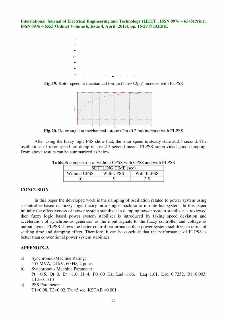
Fig.19. Rotor speed at mechanical torque (Tm+0.2pu) increase with FLPS
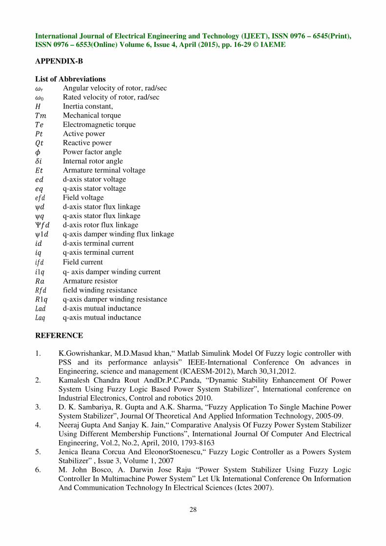
Fig.20. Rotor angle at mechanical torque (Tm+0.2 pu) increase with FLPSS
After using the fuzzy logic PSS show that, the rotor speed is steady state at 2.5 second. The
oscillations of rotor speed are damp in just 2.5 second means FLPSS are
From above results can be summarized as below
Table.3: comparison
Without CPSS
10
CONCUSION
In this paper the developed work is the damping of oscillation
a controller based on fuzzy logic theory on a single machine to infinite bus system. In this paper
initially the effectiveness of power system stabilizer in damping power system stabilizer is reviewed
then fuzzy logic based power system stabilizer is introduced by taking speed deviation and
acceleration of synchronous generator as the input signals to the fuzzy controller and voltage as
output signal. FLPSS shows the better control performance than power system stabilizer in te
settling time and damping effect. Therefore, it can be conclude that the performance of FLPSS is
better than conventional power system stabilizer.
APPENDIX-A
a) SynchronousMachine Rating:
555 MVA, 24 kV, 60 Hz, 2 poles
b) Synchronous Machine Parame
Pt =0.5, Qt=0, Et =1.0, H
L1d=0.1713
c) PSS Parameter:
T1=0.08, T2=0.02, Tw=5 sec,
International Journal of Electrical Engineering and Technology (IJEET), ISSN 0976
6553(Online) Volume 6, Issue 4, April (2015), pp. 16-29 © IAEME
27
Rotor speed at mechanical torque (Tm+0.2pu) increase with FLPS
Rotor angle at mechanical torque (Tm+0.2 pu) increase with FLPSS
After using the fuzzy logic PSS show that, the rotor speed is steady state at 2.5 second. The
damp in just 2.5 second means FLPSS areprovided
From above results can be summarized as below.
comparison of without CPSS with CPSS and with FLPSS
SETTLING TIME (sec)
Without CPSS With CPSS With FLPSS
10 5 2.5
In this paper the developed work is the damping of oscillation related to power system using
a controller based on fuzzy logic theory on a single machine to infinite bus system. In this paper
initially the effectiveness of power system stabilizer in damping power system stabilizer is reviewed
wer system stabilizer is introduced by taking speed deviation and
acceleration of synchronous generator as the input signals to the fuzzy controller and voltage as
output signal. FLPSS shows the better control performance than power system stabilizer in te
settling time and damping effect. Therefore, it can be conclude that the performance of FLPSS is
tional power system stabilizer.
SynchronousMachine Rating:
555 MVA, 24 kV, 60 Hz, 2 poles
Synchronous Machine Parameter:
H=4, F0=60 Hz, Lad=1.66, Laq=1.61, L1q
=5 sec, KSTAB =0.001
(IJEET), ISSN 0976 – 6545(Print),
© IAEME
Rotor speed at mechanical torque (Tm+0.2pu) increase with FLPSS
Rotor angle at mechanical torque (Tm+0.2 pu) increase with FLPSS
After using the fuzzy logic PSS show that, the rotor speed is steady state at 2.5 second. The
provided good damping.
of without CPSS with CPSS and with FLPSS
related to power system using
a controller based on fuzzy logic theory on a single machine to infinite bus system. In this paper
initially the effectiveness of power system stabilizer in damping power system stabilizer is reviewed
wer system stabilizer is introduced by taking speed deviation and
acceleration of synchronous generator as the input signals to the fuzzy controller and voltage as
output signal. FLPSS shows the better control performance than power system stabilizer in terms of
settling time and damping effect. Therefore, it can be conclude that the performance of FLPSS is
L1q=0.7252, Ra=0.003,
International Journal of Electrical Engineering and Technology (IJEET), ISSN 0976 – 6545(Print),
ISSN 0976 – 6553(Online) Volume 6, Issue 4, April (2015), pp. 16-29 © IAEME
28
APPENDIX-B
List of Abbreviations
!+ Angular velocity of rotor, rad/sec
!0 Rated velocity of rotor, rad/sec
, Inertia constant,
$- Mechanical torque
$. Electromagnetic torque
/0 Active power
10 Reactive power
2 Power factor angle
34 Internal rotor angle
50 Armature terminal voltage
.6 d-axis stator voltage
.7 q-axis stator voltage
.86 Field voltage
ѱ6 d-axis stator flux linkage
ѱ7 q-axis stator flux linkage
Ѱ86 d-axis rotor flux linkage
ѱ16 q-axis damper winding flux linkage
46 d-axis terminal current
47 q-axis terminal current
486 Field current
417 q- axis damper winding current
9: Armature resistor
986 field winding resistance
917 q-axis damper winding resistance
;:6 d-axis mutual inductance
;:7 q-axis mutual inductance
REFERENCE
1. K.Gowrishankar, M.D.Masud khan,“ Matlab Simulink Model Of Fuzzy logic controller with
PSS and its performance anlaysis” IEEE-International Conference On advances in
Engineering, science and management (ICAESM-2012), March 30,31,2012.
2. Kamalesh Chandra Rout AndDr.P.C.Panda, “Dynamic Stability Enhancement Of Power
System Using Fuzzy Logic Based Power System Stabilizer”, International conference on
Industrial Electronics, Control and robotics 2010.
3. D. K. Sambariya, R. Gupta and A.K. Sharma, “Fuzzy Application To Single Machine Power
System Stabilizer”, Journal Of Theoretical And Applied Information Technology, 2005-09.
4. Neeraj Gupta And Sanjay K. Jain,“ Comparative Analysis Of Fuzzy Power System Stabilizer
Using Different Membership Functions”, International Journal Of Computer And Electrical
Engineering, Vol.2, No.2, April, 2010, 1793-8163
5. Jenica Ileana Corcua And EleonorStoenescu,“ Fuzzy Logic Controller as a Powers System
Stabilizer” , Issue 3, Volume 1, 2007
6. M. John Bosco, A. Darwin Jose Raju “Power System Stabilizer Using Fuzzy Logic
Controller In Multimachine Power System” Let Uk International Conference On Information
And Communication Technology In Electrical Sciences (Ictes 2007).

International Journal of Electrical Engineering and Technology (IJEET), ISSN 0976 – 6545(Print),
ISSN 0976 – 6553(Online) Volume 6, Issue 4, April (2015), pp. 16-29 © IAEME
29
7. MdShah Majid, HasimahAbdRahman, Othman B. Jais “Study of Fuzzy Logic Power System
Stabilizer” 2002 Student Conference on Research and Development Proceedings, Shah Alam
Malaysia.
8. A.Hariri, O.P.Malik “A Fuzzy Logic Based Power System Stabilizer With Learning
Ability”IEEE Transactions On Energy Conversion, Vol.11, No. 4, December 1996
9. Tamer Abdelazim, O.P.Malik “An Adaptive Power System Stabilizer Using On-Line Self-
Learning Fuzzy System” 0-7803-7989-6/03/02003IEEE
10. P.Kundur,“Power System Stability And Control”, New york: Mcgraw-Hill,1994.
11. Mrs. Babita nanda, “Comparison Of Optimization Technique of Power System Stabilizer by
Using GEA /Phase Compensation Technique” International Journal of Electrical Engineering
& Technology (IJEET), Volume 4, Issue 4, 2013, pp. 225 - 231, ISSN Print : 0976-6545,
ISSN Online: 0976-6553.
12. Ms.Tan Qian Yi, Mr. Gowrishankar Kasilingam and Mr.Raman Raghuraman, “Optimal-
Tuning of PID Power System Stabilizer In Simulink Environment For A Synchronous
MachinE” International Journal of Electrical Engineering & Technology (IJEET), Volume 4,
Issue 1, 2013, pp. 115 - 123, ISSN Print : 0976-6545, ISSN Online: 0976-6553.
13. Gowrishankar Kasilingam, “Effect of Genetic PID Power System Stabilizer For A
Synchronous Machine” International Journal of Advanced Research in Engineering &
Technology (IJARET), Volume 4, Issue 4, 2013, pp. 8 - 21, ISSN Print: 0976-6480, ISSN
Online: 0976-6499