Embed Size (px)
Citation preview

3-PHASE STEPPING SYSTEMS
Ver.3
22
Stepping Motor Motor Size: 42 mm sq. to 60 mm sq.

3
Host Devices
Power supply
PLC etc.Pulse signal
Driver
Motor
Motor cable
(Option)
Noise filterElectromagnetic contactor
Molded case circuit breaker
Protects the power line. Cuts off circuit in the event of overcurrent.
Switches driver power on/off. Use together with a surge protector.
Filters out incoming noise from power line
SANMOTION F3 is a 3-phase stepping system that provides precise positioning with simple control.
The typical basic step angle is 1.2°, precisely controlled by pulse signals.
Stepping Motor ■Motorfl ange size
Basic step angleHolding torque
[N・m (oz・in) MIN.]Model number Page
42mm sq.
(1.65inch sq.)1.2°
0.196 (27.75) 103H5332-03□0 P.4
0.265 (37.53) 103H5333-03□0 P.4
50mm sq.
(1.97inch sq.)1.2°
0.44 (62.31) 103H6332-03□0 P.5
0.58 (82.13) 103H6333-03□0 P.5
56mm sq.
(2.20inch sq.)1.2°
0.69 (97.71) 103H7332-03□0 P.6
1.1 (155.77) 103H7333-03□0 P.6
60mm sq.
(2.36inch sq.)1.2°
0.95 (134.53) 103H7832-03□0 P.7
1.68 (237.90) 103H7833-03□0 P.7
Set Model Confi guration
System Confi guration
4
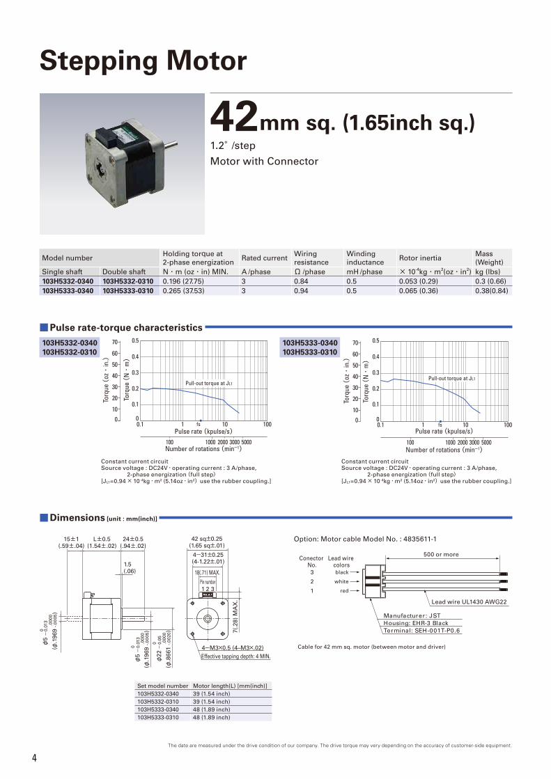
42mm sq. (1.65inch sq.)1.2°/step
Motor with Connector
Constant current circuitSource voltage : DC24V・operating current : 3 A/phase, 2-phase energization(full step)[JL1=0.94× 10⁻⁴kg・m2 (5.14oz・in2)use the rubber coupling.]
0.1 1 10 100
2000 3000 5000100 1000
Pulse rate (kpulse/s)
Number of rotations (min-1)
fs
0.1
0.2
0.3
0.4
0.5
0
Pull-out torque at JL1
60
50
40
30
20
10
70
0
Torq
ue (
oz・
in.)
Torq
ue (
N・
m)
Constant current circuitSource voltage : DC24V・operating current : 3 A/phase, 2-phase energization(full step)[JL1=0.94× 10⁻⁴kg・m2 (5.14oz・in2)use the rubber coupling.]
Torq
ue (
N・
m)
0.1 1 10 100Pulse rate (kpulse/s)
2000 3000 5000100 1000Number of rotations (min-1)
fs
0.1
0.2
0.3
0.4
0.5
0
60
50
40
30
20
10
70
0
Torq
ue (
oz・
in.)
Pull-out torque at JL1
Model numberHolding torque at
2-phase energizationRated current
Wiring
resistance
Winding
inductanceRotor inertia
Mass
(Weight)
Single shaft Double shaft N・m (oz・in) MIN. A /phase Ω /phase mH /phase × 10-4kg・m
2(oz・in
2) kg (lbs)
103H5332-0340 103H5332-0310 0.196 (27.75) 3 0.84 0.5 0.053 (0.29) 0.3 (0.66)
103H5333-0340 103H5333-0310 0.265 (37.53) 3 0.94 0.5 0.065 (0.36) 0.38(0.84)
Pulse rate-torque characteristics ■
Set model number Motor length(L) [mm(inch)]
103H5332-0340 39 (1.54 inch)
103H5332-0310 39 (1.54 inch)
103H5333-0340 48 (1.89 inch)
103H5333-0310 48 (1.89 inch)
Effective tapping depth: 4 MIN.
1 2 3
4-M3×0.5 (4–M3×.02)
L±0.5(1.54±.02)
24±0.5(.94±.02)
42 sq±0.25(1.65 sq±.01)
4-31±0.25(4-1.22±.01)
18(.71) MAX.
7(.
28
) M
AX
.
Pin number
1.5(.06)
15±1(.59±.04)
0.0
13
φ5-
0.0
13
0φ
5
.0000
(φ.1
96
9 -
.00
05)
.0
000
(φ.1
96
9 -
.00
05)
.0
000
(φ.8
66
1 -
.0020)
-0.0
13
0.0
5
φ2
2-
0.0
5
Dimensions ■ [unit : mm(inch)]
The date are measured under the drive condition of our company. The drive torque may very depending on the accuracy of customer-side equipment.
Lead wire colors
Conector No.
Cable for 42 mm sq. motor (between motor and driver)
black
white
red
3
2
1
Option: Motor cable Model No. : 4835611-1
Lead wire UL1430 AWG22
Manufacturer : JST
Housing: EHR-3 Black
Terminal: SEH-001T-P0.6
500 or more
Stepping Motor
103H5333-0340103H5333-0310
103H5332-0340103H5332-0310
5The date are measured under the drive condition of our company. The drive torque may very depending on the accuracy of customer-side equipment.
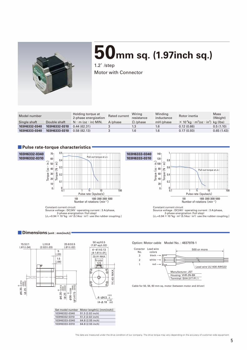
50mm sq. (1.97inch sq.)1.2°/step
Motor with Connector
Constant current circuitSource voltage : DC24V・operating current : 3 A/phase, 2-phase energization(full step)[JL1=0.94× 10⁻⁴kg・m2 (5.14oz・in2)use the rubber coupling.]
fs
Torq
ue (
N・
m)
0.1 1 10 100
2000 3000 5000100 1000
Pulse rate (kpulse/s)
Number of rotations (min-1)
0.1
0.2
0.3
0.4
0.5
0
60
50
40
30
20
10
70
0
Torq
ue (
oz・
in.)
Pull-out torque at JL1
Constant current circuitSource voltage : DC24V・operating current : 3 A/phase, 2-phase energization(full step)[JL1=0.94× 10⁻⁴kg・m2 (5.14oz・in2)use the rubber coupling.]
fs
Torq
ue (
N・
m)
0.1 1 10 100Pulse rate (kpulse/s)
2000 3000 5000100 1000Number of rotations (min-1)
0.2
0.4
0.6
0.8
1
0
Pull-out torque at JL1
120
100
80
60
40
20
140
0
Torq
ue (
oz・
in.)
Model numberHolding torque at
2-phase energizationRated current
Wiring
resistance
Winding
inductanceRotor inertia
Mass
(Weight)
Single shaft Double shaft N・m (oz・in) MIN. A /phase Ω /phase mH /phase × 10-4kg・m
2(oz・in
2) kg (lbs)
103H6332-0340 103H6332-0310 0.44 (62.31) 3 1.3 1.6 0.12 (0.66) 0.5 (1.10)
103H6333-0340 103H6333-0310 0.58 (82.13) 3 1.6 1.6 0.17 (0.93) 0.65 (1.43)
Dimensions ■ [unit : mm(inch)]
Pulse rate-torque characteristics ■
Set model number Motor length(L) [mm(inch)]
103H6332-0340 51.3 (2.02 inch)
103H6332-0310 51.3 (2.02 inch)
103H6333-0340 64.8 (2.55 inch)
103H6333-0310 64.8 (2.55 inch)
+0.5
4-φ4.5 0.0
Pin number
15.5±1(.61±.04)
L±0.8(2.02±.03)
20.6±0.5(.81±.02)
1.5(.06)
5(.20)
0.0
00
φ6.3
5-
0.0
13
0.0
00
φ6.3
5-
0.0
13
0.0
00
φ3
6-
0.0
39
50 sq±0.5(1.97 sq±.02)
4-41±0.13(4-1.61±.01)
23(.91) MAX.
11(.
43
) M
AX
.
123
.0
000
(φ.2
5 -
.00
05)
.0
000
(φ.2
5 -
.00
05)
.0000
(φ1.
417
3 -
.0015)
+.02(4–φ.18 .00)
Lead wire colors
black
white
red
Conector No.
Cable for 50, 56, 60 mm sq. motor (between motor and driver)
3
2
1
Option: Motor cable Model No. : 4837978-1
Lead wire UL1430 AWG22
Manufacturer: JST
Housing: VHR-3N-BK
Terminal: SVH-21T-P1.1
500 or more
103H6333-0340103H6333-0310
103H6332-0340103H6332-0310

6The date are measured under the drive condition of our company. The drive torque may very depending on the accuracy of customer-side equipment.
56mm sq. (2.20inch sq.)1.2°/step
Motor with Connector
Constant current circuitSource voltage : DC24V・operating current : 3 A/phase, 2-phase energization(full step)[JL1=0.94× 10⁻⁴kg・m2 (5.14oz・in2)use the rubber coupling.]
fs
Torq
ue (
N・
m)
0.1 1 10 100Pulse rate (kpulse/s)
0.2
0.4
0.6
0.8
1
0
2000 3000 5000100 1000Number of rotations (min-1)
120
100
80
60
40
20
140
0
Torq
ue (
oz・
in.)
Pull-out torque at JL1
Constant current circuitSource voltage : DC24V・operating current : 3 A/phase, 2-phase energization(full step)[JL1=2.6× 10⁻⁴kg・m2 (14.22oz・in2)use the rubber coupling.]
fs
Torq
ue (
N・
m)
0.1 1 10 100Pulse rate (kpulse/s)
2000 3000 5000100 1000Number of rotations (min-1)
0.4
0.8
1.2
1.6
2
0
Torq
ue (
oz・
in.)
Pull-out torque at JL1
250
200
150
100
50
0
Model numberHolding torque at
2-phase energizationRated current
Wiring
resistance
Winding
inductanceRotor inertia
Mass
(Weight)
Single shaft Double shaft N・m (oz・in) MIN. A /phase Ω /phase mH /phase × 10-4kg・m
2(oz・in
2) kg (lbs)
103H7332-0340 103H7332-0310 0.69 (97.71) 3 1.4 1.8 0.21 (1.15) 0.65 (1.43)
103H7333-0340 103H7333-0310 1.1 (155.77) 3 1.7 2.4 0.36 (1.97) 0.98 (2.16)
Pulse rate-torque characteristics ■
Dimensions ■ [unit : mm(inch)]
Set model number Motor length(L) [mm(inch)]
103H7332-0340 53.8 (2.12 inch)
103H7332-0310 53.8 (2.12 inch)
103H7333-0340 75.8 (2.98 inch)
103H7333-0310 75.8 (2.98 inch)
3Pin number
15.5±1(.61±.04)
L±0.8(2.12±.03)
20.6±0.5(.81±.02)
5 (.20)
1.5 (.06)
φ38
.1±0
.025
(φ1.
5±0.
010)
0.00
0φ
6.35-
0.01
30 .00
0φ
6.35-
0.01
3
1 2
23(.91) MAX.
11(.
43
) M
AX
.
4-47.14±0.13(4-1.86±.01)
56 sq±0.5(2.20 sq±.02)
+0.5
4-φ4.5 0.0
.0
000
(φ.2
5 -
.00
05)
.0
000
(φ.2
5 -
.00
05)
+.02(4–φ.18 .00)
Lead wire colors
black
white
red
Conector No.
Cable for 50, 56, 60 mm sq. motor (between motor and driver)
3
2
1
Option: Motor cable Model No. : 4837978-1
Lead wire UL1430 AWG22
Manufacturer: JST
Housing: VHR-3N-BK
Terminal: SVH-21T-P1.1
500 or more
103H7333-0340103H7333-0310
103H7332-0340103H7332-0310
7The date are measured under the drive condition of our company. The drive torque may very depending on the accuracy of customer-side equipment.
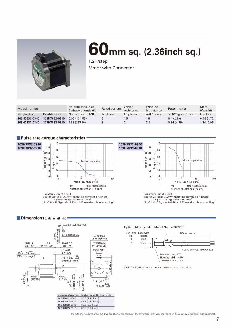
60mm sq. (2.36inch sq.)1.2°/step
Motor with Connector
Constant current circuitSource voltage : DC24V・operating current : 3 A/phase, 2-phase energization(full step)[JL1=2.6× 10⁻⁴kg・m2 (14.22oz・in2)use the rubber coupling.]
fs
Torq
ue (
N・
m)
0.1 1 10 100Pulse rate (kpulse/s)
2000 3000 5000100 1000Number of rotations (min-1)
0.4
0.8
1.2
1.6
2
0
Torq
ue (
oz・
in.)
Pull-out torque at JL1
250
200
150
100
50
0
Constant current circuitSource voltage : DC24V・operating current : 3 A/phase, 2-phase energization(full step)[JL1=7.4× 10⁻⁴kg・m2 (40.46oz・in2)use the rubber coupling.]
fs0.1 1 10 100Pulse rate (kpulse/s)
2000 3000 5000100 1000Number of rotations (min-1)
Torq
ue (
N・
m)
0.4
0.8
1.2
1.6
2
0
Torq
ue (
oz・
in.)
Pull-out torque at JL1
250
200
150
100
50
0
Model numberHolding torque at
2-phase energizationRated current
Wiring
resistance
Winding
inductanceRotor inertia
Mass
(Weight)
Single shaft Double shaft N・m (oz・in) MIN. A /phase Ω /phase mH /phase × 10-4kg・m
2(oz・in
2) kg (lbs)
103H7832-0340 103H7832-0310 0.95 (134.53) 3 1.5 1.8 0.4 (2.19) 0.78 (1.72)
103H7833-0340 103H7833-0310 1.68 (237.90) 3 2 3.2 0.84 (4.59) 1.34 (2.95)
Dimensions ■ [unit : mm(inch)]
Pulse rate-torque characteristics ■
Set model number Motor length(L) [mm(inch)]
103H7832-0340 53.8 (2.12 inch)
103H7832-0310 53.8 (2.12 inch)
103H7833-0340 85.8 (3.98 inch)
103H7833-0310 85.8 (3.98 inch)
0.0
00
φ3
6-
0.0
39
1 23Pin number
(Effective length)
S
S
S
S
Cross section S-S
15.5±1(.61±.04)
L±0.8(2.12±.03)
20.6±0.5(.81±.02)
7 (.28)
1.5 (.06)+1
15 +0
R4 MIN.(R.157 MIN)
R4 MIN.(R.157 MIN)0
.00
0φ
8-
0.0
15
0.0
00
φ8-
0.0
15
23(.91) MAX.
4-50±0.13(4-1.97±.01)
60 sq±0.5(2.36 sq±.02)
11(.
43
) M
AX
.
7.5±0.2 (.2953±.0079)90°
7.5±
0.2
(.2
95
3±.0
07
9)
+.04(.59 .00)
(Effective length)
+115 +0
+.04(.59 .00)
+0.5
4-φ4.5 0.0
.0
000
(φ.3
15
0 -
.00
06)
.0
000
(φ.3
15
0 -
.00
06)
.0000
(φ1.
417
3 -
.0015)
+.02(4–φ.18 .00)
Lead wire colors
black
white
red
Conector No.
Cable for 50, 56, 60 mm sq. motor (between motor and driver)
3
2
1
Option: Motor cable Model No. : 4837978-1
Lead wire UL1430 AWG22
Manufacturer: JST
Housing: VHR-3N-BK
Terminal: SVH-21T-P1.1
500 or more
103H7833-0340103H7833-0310
103H7832-0340103H7832-0310
8
(1)
(3)(2)
Model number 103H533□ 103H633□ 103H733□ 103H783□Ambient operation
temperature- 10~+ 50℃
Storage temperature - 20~+ 65℃Ambient operation humidity 20~ 90% RH (no condensation)
Storage humidity 5~ 95% RH (no condensation)
Vibration resistanceVibration frequency 10 to 500 Hz, total amplitude 1.52 mm (10 to 70 Hz), vibration acceleration 147 m/s
2
(70 to 500 Hz), sweep time 15 min/cycle, 12 sweeps in each X, Y and Z direction.
Impact resistance490m/s
2 of acceleration for 11 ms with half-sine wave applying three times for X, Y, and Z axes each,
18 times in total.
Insulation class Class B (+130℃ )
Withstand voltageWithout abnormality when applying 50/60 Hz, 1000 V AC(500 V AC for103H533□)for 1 minute(leakage current 1 mA)between winding and frame at normal temperature and humidity.
Insulation resistance Not less then 100MΩ between winding and frame by DC500 V megger at normal temperature and hamidity.
Protection grade IP40
Wiringtemperature increase 80 K MAX.(Based on Sanyo Denki standard.)Standing angle error ± 0.06°
Axial play (Note 1) 0.075 mm(0.003 inch)MAX.
Load : 4.4N(1 lbs)0.075 mm(0.003 inch)MAX.
Load : 9N(2 lbs)
Radial play (Note 2) 0.075 mm(0.003 inch)MAX.
Load : 4.4N(1lbs)Shaft runout 0.025mm (0.001 inch)
Concentricity of mounting
spigot relative to shaftφ 0.05mm (0.002 inch) φ 0.075mm (0.003 inch)
Perpendicularity of mounting
surface relative to shaft0.1mm (0.004 inch) 0.075mm (0.003 inch)
General specifi cations
(Note1) Axial play: Shaft displacement under axial load.
(Note2) Radial play: Shaft displacement under radial load applied 1/3rd of the length from the end of the shaft.
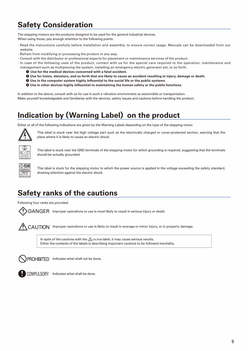
Internal connection and rotational direction■ Internal connection
( )Connector pin number
■ Direction of motor rotate
When DC-energized in the order below, the rotational direction must be
counterclockwise viewed from the output axis side.
TypeConector type pin number
(1) (2) (3)
Energization
order
1 + -
2 + -
3 + -
4 - +
5 - +
6 - +
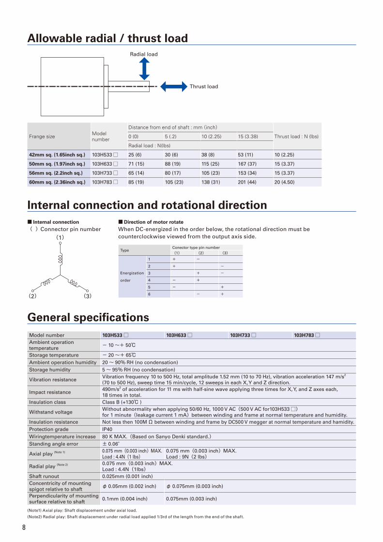
Frange size Modelnumber
Distance from end of shaft : mm(inch)
Thrust load : N (lbs)0 (0) 5 (.2) 10 (2.25) 15 (3.38)
Radial load : N(lbs)
42mm sq. (1.65inch sq.) 103H533□ 25 (6) 30 (6) 38 (8) 53 (11) 10 (2.25)
50mm sq. (1.97inch sq.) 103H633□ 71 (15) 88 (19) 115 (25) 167 (37) 15 (3.37)
56mm sq. (2.2inch sq.) 103H733□ 65 (14) 80 (17) 105 (23) 153 (34) 15 (3.37)
60mm sq. (2.36inch sq.) 103H783□ 85 (19) 105 (23) 138 (31) 201 (44) 20 (4.50)
Radial load
Thrust load
Allowable radial / thrust load
9
Safety ConsiderationThe stepping motors are the products designed to be used for the general industrial devices.
When using those, pay enough attention to the following points.
・ Read the instructions carefully before installation and assembly, to ensure correct usage. Manuals can be downloaded from our
website.
・ Refrain from modifying or processing the product in any way.
・ Consult with the distributor or professional experts for placement or maintenance services of the product.
・ In case of the following uses of the product, contact with us for the special care required to the operation, maintenance and
management such as multiplexing the system, installing an emergency electric generator set, or so forth.
❶ Use for the medical devices concerned with a fatal accident.❷ Use for trains, elevators, and so forth that are likely to cause an accident resulting in injury, damage or death.❸ Use in the computer system highly infl uential to the social life or the public systems.❹ Use in other devices highly infl uential to maintaining the human safety or the public functions.
In addition to the above, consult with us for use in such a vibration environment as automobile or transportation.
Make yourself knowledgeable and familiarize with the devices, safety issues and cautions before handling the product.
Indication by(Warning Label)on the productEither or all of the following indications are given by the Warning Labels depending on the type of the stepping motor.
This label is stuck near the high voltage part such as the electrically charged or cover-protected section, warning that the
place where it is likely to cause an electric shock.
This label is stuck near the GND terminals of the stepping motor for which grounding is required, suggesting that the terminals
should be actually grounded.
This label is stuck for the stepping motor to which the power source is applied in the voltage exceeding the safety standard,
drawing attention against the electric shock.
Safety ranks of the cautionsFollowing four ranks are provided.
Improper operations or use is most likely to result in serious injury or death.
Improper operations or use is likely to result in average or minor injury, or in property damage.
In spite of the cautions with the label, it may cause serious results.
Either the contents of the labels is describing important cautions to be followed inevitably.
Indicates what shall not be done.
Indicates what shall be done.
10
<General matters>1. Do not use the product in an explosive, flammable or corrosive
atmosphere, watery place or near a combustible material. Doing so may cause injury or fi re.
2. Have a person with expert knowledge for performing the transportation,placement,wiring, operation, maintenance or inspection of the product. Without such knowledge, it may cause an electric shock, injury or fi re.
3. Do not work for wiring, maintenance servicing or inspection with the electric power on. Perform either of those fi ve minutes after turning the power off, or otherwise, it may cause an electric shock.
4. When the protective functions of the product is activated, turn the power off immediately and eliminate the cause. If continuing the operation without eliminating the cause, the product may operate improperly and cause injury or a breakdown of the system devices.
5. Stepping motor may run out of order at the operating and stopping occasions, depending on the magnitude of the load. Put the product into use after confirming with the adequate trial test operation in the maximum load conditions that the product performs reliable operation. Doing otherwise may cause a breakdown of the system. (Should the product run out of order in the use to drive upward/downward, it may cause a fall of the load.)
6. Do not touch the internal parts. Doing so may cause an electric shock.
<Wiring>7. Do not connect the stepping motor directly with the commercial power
outlet. Doing so may cause an electric shock, injury or fi re. The power shall be supplied to the stepping motor through the driving circuit.
8. Use the electric power source within the rated input voltage. Using otherwise may cause fi re or an electric shock.
9. Connect the stepping motor to the ground. Using without grounding may cause an electric shock.
10. Do not harm, forcibly put a stress, or load a heavy article on the cable or get it caught between the articles. Doing so may cause an electric shock.
11. Perform wiring with the power cable as instructed by the wiring diagram. Doing otherwise may cause an electric shock or fi re.
<Operation>12. Be sure not to touch the rotating part of the stepping motor during its
operation. Touching it may cause injury.13. Neither reach or touch the electric terminals while electric power is on. Doing so may cause an electric shock.14. Never disconnect any of the connectors while electric power is on. Doing
so may cause an electric shock and corruption.
<General matters>1. Do not use the driver or the stepping motor outside the specified
conditions. Doing so may cause an electric shock, injury or fi re.2. Do not insert a fi nger or a thing into the opening of the product. Doing so
may cause an electric shock, injury or fi re.3. Do not use the damaged driver or stepping motor. Doing so may cause
injury, fi re or the like.4. Use the driver and stepping motor in the designated combination. Using
otherwise may cause fi re or a trouble.5. Be careful that the temperature rises in the operating driver, stepping
motor or peripheral devices. Failure to be careful may cause a burn.
<Unpacking>6. Unpack while confi rming the ceiling. Failure to do so may cause injury.7. Confi rm if the product is the one having been ordered. Installing an
incorrect product may cause a breakdown.
<Wiring>8. Do not perform measurement of the insulation resistance or withstand
insulation voltage of the product. Doing so may cause a breakdown. Instead, contact with us for such inspection.
9. Perform wiring conforming to the technical standards of electric facility or the internal rule. Doing otherwise may cause burning or fi re.
10. Ensure that wiring has been correctly done. Operating without correct wiring may cause the stepping motor to run out of control and result in injury.
11. Take insulation process for the attached condenser or the external resistance connection terminals. Failure to do so may cause an electric shock.
<Placement>12. Do not climb or attach a heavy article on the product. Doing so may cause
injury.13. Neither block nor stuff the aspiration/exhaust vent with a foreign particle. Doing so may cause fi re.14. Follow the instructions for the direction to place. Failure to do so may
cause a trouble.
15. Place the product with a great care so as to prevent from the danger such as a tumble or a turnover.
16. Mount the product on an incombustible material such as metal. Doing otherwise may cause fi re.
17. Confirm the rotating direction before connecting with the mechanical device. Failure to do so may cause injury or a breakdown.
18. Do not touch the motor output spindle (including the key slot and gears) with a bare hand. Doing so may cause injury.
<Operation>19. The stepping motor is not equipped with any protective device. Take
protective measures using an over-current protective relay, a ground fault interrupter, a protective device from excess temperature, and an emergency stopping device. Failure to do so may cause injury or fi re.
20. Do not touch the product for a period after the power is on or has been turned off, since the driver and stepping motor remain in the high temperature. Doing so may cause burns. Especially the temperature rises considerably of the stepping motor depending on the operating conditions. Use the motor on the condition so that its surface temperature becomes 100°C or under
21. Stop the operation immediately when an emergency occurs. Failure to do so may cause an electric shock, injury or fi re.
22. Do not change adjustment to an extreme, for such a change results in the unstable operation. Doing so may cause injury.
23. When conducting the trial operation, make the stepping motor fixed fi rmly, and confi rm the operation by disconnecting with the mechanical system before connecting with it. Failure to do so may cause injury.
24. When the alarm has been activated, eliminate the cause and ensure the safety to resume operation. Failure to do so may cause injury.
25. When the electric power recovers after the momentary interruption, do not approach the devices because the system may re-start operation by itself. (Set the system so as to secure the safety even when it re-start on such occasion.) Failure to do so may cause injury.
26. Confirm that the electric power supply is all proper conforming to the specifi cations. Failure to do so may cause a trouble.
27. The brake mechanism of the motor with the electro-magnetic brake is to hold the movable section and the motor position. Do not use it as a safety measure, or doing so may cause the breakdown of the system.
28. Fix the key fi rmly when operating the motor with key individually. Failure to do so may cause injury.
<Maintenance services>29. Be careful when performing maintenance services or inspection about
the temperature which rises highly in the driver and stepping motor frame. Failure to do so may cause burns.
30. Contact with us for repair. If the product is disassembled by the user, it may put it out of action.
<Transportation>31. Handle the product with care during transportation so as to prevent from
the danger such as a tumble or a turnover.32. Do not hold with the cable or the motor spindle. Doing so may cause a
trouble or injury.
<Retirement>33. When scrapping the stepping motor, treat it for the general industrial
waste.
<Storage>1. Avoid the place exposed to rain or water drops, or in an environment with
hazardous gas or liquid for storing the product. Failure to do so may cause a trouble.
<Maintenance services>2. Do not assemble or repair the product. Doing so may cause fi re or an electric
shock.
<General matters>3. Do not remove the rating plate.
<Storage>1. Store the product within the specified conservation temperature and
humidity in the place not exposed to the sun beam.
<Operation>2. Install an external emergency stop circuit to turn the power off for the
instant halt of operation.3. Put the product into operation in the specifi ed ambient temperature and
humidity.
<Transportation>4. Excess loading of the product on the carrier may cause the load to fall in
pieces. Follow the instructions given outside the package.

❶ Name of target equipment Equipment name, category (transport, processing, test, other)
❾ Encoder type
Encoder type specified ( yes / no )
Yes:(Wiring saving incremental encoder, battery backup absolute encoder, absolute encoder for
incremental system, battery-less absolute encoder)
Resolution( )
❷ Name of servo axis Axis name, axial mechanism (horizontal/vertical), brake mechanism (yes/no)
❸ Current condition of above axis Manufacturer Name ( ) Series Name ( ) Motor Capacity ( ) Hydraulic, Mechanical, or New System ( )
❹ Positioning accuracy ± mm・± μm
❺ Operation pattern
Accelerationα:__G・___[m/s2]
Feeding SpeedV:____[m/s]
Feeding
Speed
[m/sec]
【Reference formula】【1G=9.8[m/s2]、1[m/s2]≒0.1G】【α[m/s2]=V[m/sec]÷t1[sec]】【D[m]=V[m/sec]×(t1+t2)[sec]】
Moving DistanceD:___[m]
(Stroke)
❻ MechanismBall-screw/screw-rotation type (horizontal/vertical), ball-screw/nut-rotation type (horizontal/vertical),
rack and pinion (horizontal/vertical), belt/chain (horizontal/vertical), rotary table, roll feed, other
❼ Mechanical structure
WT(table mass) kg WL(work mass) kg WA(mass of other drive parts) kg
WR(rack mass) kg WB(belt/chain mass) kg WC(counterbalance mass) kg
Fa(external force axial direction) N Fb(ball-screw preload) N T(roll pushing force) N
Dr1(drive-side roll diameter) mm Dr2(follower-side roll diameter) mm
Lr1(drive-side roll length) mm Lr2(follower-side roll length) mm G(reduction ratio)JG(speed-reducer inertia) kg・m2 JC(coupling inertia) kg・m2
JN(nut inertia) kg・m2 JO(other motor-axis conversion inertia) kg・m2
Db(ball-screw diameter) mm Lb(ball-screw axial length) mm Pb(ball -screw lead) mm
Dp(pinion/pulley diameter) mm Lp(pinion axial length) mm tp(pully thickness) mm
Dt(table diameter) mm Dh(table-support dianeter) mm LW(load shift from axis) mm
Ds(table shaft diameter) mm Ls(table shaft length) mm
ρ(specific gravity of ball-screw/pinion/pulley/table-shaft material) kg・cm3
μ(friction coefficient between sheet and shiliding-surface/support-section/roll) ρ1(specific gravity of roll-1 material) kg/cm3
ρ2(specific gravity of roll-2 material) kg/cm3 κ(internal friction coefficient of preload nut)η(mechanical efficiency) JL(load inertia of motor-axis conversion) kg・m2
TF(friction torque of motor axis conversion) N・m Tu(imbalance torque of motor axis conversion) N・m
❿ Input format Position , velocity , torque , other ( )
⓫ Host equipment (controller) Sequencer , laptop , customer-developed product , Sanyo dennki-provided , other ( )
⓭ Estimated production Single product: ( ) units/mouth ( ) units/year
⓮ Development schedule Prototype period: ( ) Year ( ) Month Production period: ( ) Year ( ) Month
Various measures Related documentation ( already submitted; send later by mail) Visit/PR desired ( yes / no ) Meeting desired ( yes / no )⓯
⓰Miscellaneous
(questions, pending problems,
unresolved issues, etc.)
⓬ Usage environment and other requirements Cutting , clean-room use , anti-dust measures , other ( )
❽ Speed reducer Customer-provided ( / )・Sanyo denki standard(planet/spur/no-backlash-planet / ) other( / )
Item Contents
Time
Inquiry Check Sheet For more information regarding any products or services described here in,
please contact your nearest office listed on the back of this catalog.
Date:To SANYO DENKI Co.,LTD.
Company:
Department:
Name:
Tel: FAX:
E-mail:
3-PHASE STEPPING SYSTEMS
Ver.3
*For any question or inquiry regarding the above, contact our Sales Department.
■ Precautions For AdoptionFailure to follow the precautions on the right may cause moderate injury and property damage, or in some circumstances,could lead to a serious accident. Always follow all listed precautions.
CATALOG NO. S0833B004 ’12.10.IT
SANMOTION_F3_STEPPING_Ver3_ENG_面付.indd 1-2 2012/10/03 13:17:23
CATALOG No.S0833B011 ,18.4.IT
https://www.sanyodenki.com
TEL: +81 3 5927 1020
TEL: +86 21 6235 1107
TEL: +1 310 783 5400
TEL: +33 1 48 63 26 61
TEL: +852 2312 6250
468 Amapola Avenue Torrance, CA 90501, U.S.A.
3-33-1 Minami-Otsuka, Toshima-ku, Tokyo 170-8451, Japan
P.A. Paris Nord Ⅱ, 48 Allée des Erables-VILLEPINTE, BP.57286, F-95958 ROISSY CDG Cedex, France
Room 2106-2110, Bldg A, Far East International Plaza, No.319, Xianxia Road, Shanghai, 200051, China
TEL: +86 10 6522 2160Room1222, Tower B, Beijing COFCO Plaza, No.8 Jianguomennei Dajie, Dong Cheng District, Beijing 100005 China
Room 2305, 23/F, South Tower, Concordia Plaza, 1 Science Museum Road, TST East, Kowloon, Hong Kong
TEL: +86 755 3337 38682F 02-11, Shenzhen International Chamber of Commerce Tower, No.168 Fuhua 3 Road, Futian District, Shenzhen, 518048 China
TEL: +66 2261 8670388 Exchange Tower, 25th Floor, Unit 2501-1, Sukhumvit Road, Klongtoey, Klongtoey, Bangkok 10110 Thailand
TEL: +91 44 420 384 72#14 (Old No.6/3), Avenue Road, Nungambakkam, Chennai - 600034, Tamil Nadu, India
Beijing Branch
TEL: +86 22 2320 1186Room AB 16th Floor TEDA Building, No. 256 Jie Fang Nan Road, Hexi District, Tianjin 300042 ChinaTianjin Branch
TEL: +86 28 8661 6901Room2105B, Block A, Times Plaza, 2 Zongfu Road, Jinjiang District, Chengdu, 610016 ChinaChengdu Branch
TEL: +49 6196 76113 0
TEL: +82 2 773 5623
TEL: +886 2 2511 3938
TEL: +65 6223 1071
Frankfurter Strasse 80-82, 65760 Eschborn, Germany
988 Toa Payoh North, #04-08, Singapore 319002
N-711, 7F, Chia Hsin 2nd Bldg., No.96, Sec.2, Zhongshan N. Rd., Taipei 10449, Taiwan
15F, KDB Building, 372, Hangang-daero, Yongsan-gu, Seoul, 04323, Korea
TEL: + 62 21 252 3202Summitmas II 4th Floor, Jl. Jend. Sudirman Kav.61-62, Jakarta 12190, IndonesiaIndonesia Representative Office
TEL: +82 51 796 5151 8F, CJ Korea Express Bldg., 119, Daegyo-ro, Jung-gu, Busan, 48943, KoreaBusan Branch
*For any question or inquiry regarding the above, contact our Sales Department.
■ Precautions For AdoptionFailure to follow the precautions on the right may cause moderate injury and property damage, or in some circumstances,could lead to a serious accident. Always follow all listed precautions.