Embed Size (px)
Citation preview

Power Factor Controller RVT
Installation and Operating Instructions

2 – Table of contents Power Factor Controller RVT
Table of contents Read this first .................................................................................................................... 4 1 Introduction to the controller ...................................................................................... 5
1.1 A powerful fully three phase individual controlled power factor controller ............ 5 1.2 RVT main features ................................................................................................. 5 1.3 Front view and rear view ....................................................................................... 6 1.4 Colorful touch screen interface .............................................................................. 7
2 Installation .................................................................................................................... 8 2.1 Mounting ................................................................................................................ 8 2.2 Lead connections .................................................................................................. 9 2.3 Wiring diagram..................................................................................................... 10
3 Easy start .................................................................................................................... 12 3.1 Menu navigation .................................................................................................. 12
3.1.1 Legends for the touch screen icons ............................................................ 12 3.1.2 Title bar........................................................................................................ 14 3.1.3 Setting area ................................................................................................. 15 3.1.4 Status bar .................................................................................................... 15 3.1.5 Keyboard entry screen ................................................................................ 15
3.2 Starting the RVT .................................................................................................. 16 3.3 Automatic commissioning .................................................................................... 16
3.3.1 Description .................................................................................................. 16 3.3.2 Preparation for automatic commissioning ................................................... 16 3.3.3 Automatic commissioning............................................................................ 17
4 Measurements and Settings ..................................................................................... 21 4.1 Measurements ..................................................................................................... 21
4.1.1 Overview...................................................................................................... 22 4.1.2 System values ............................................................................................. 25 4.1.3 Waveform .................................................................................................... 28 4.1.4 Meter ........................................................................................................... 29 4.1.5 Event logging ............................................................................................... 29
4.2 Settings ................................................................................................................ 31 4.2.1 Manual settings (Set Mode) ........................................................................ 32
4.2.1.1 Bank settings ........................................................................................ 32
4.2.1.2 Installation settings ............................................................................... 40
4.2.1.3 User settings ......................................................................................... 42
4.2.1.4 Protections and warnings ..................................................................... 43
4.2.1.5 Restore default settings ........................................................................ 45
4.2.2 Commissioning (SET mode) ....................................................................... 46 4.2.2.1 Automatic Commissioning .................................................................... 47
4.2.2.2 Guided Commissioning ........................................................................ 47
4.2.2.3 T Probes commissioning ...................................................................... 47
4.3 Bank Monitoring ................................................................................................... 48 4.3.1 Diagnosis ..................................................................................................... 49 4.3.2 Test function ................................................................................................ 49 4.3.3 Alarm logging .............................................................................................. 50 4.3.4 Real time clock ............................................................................................ 51
4.4 Communications .................................................................................................. 51 4.4.1 I/O configuration .......................................................................................... 55
Power Factor Controller RVT Table of contents - 3
4.4.1.1 Set languages ....................................................................................... 55
4.4.1.2 Temp unit .............................................................................................. 56
4.4.1.3 Communications settings ..................................................................... 56
4.4.2 Ethernet configurations ............................................................................... 58 4.4.3 Screen configuration ................................................................................... 59 4.4.4 About ........................................................................................................... 60 4.4.5 Mac Address ............................................................................................... 60
Appendices ...................................................................................................................... 61 A1. Dimensions ............................................................................................................ 61 A2. Technical specifications ........................................................................................ 61 A3. Testing and troubleshooting .................................................................................. 64 A4. Post Alarm Restarting Procedure .......................................................................... 67 A5. Voltage measurement and power supply connection ........................................... 68 A6. Phase shift table (applicable to Base Model) ........................................................ 69 A7. CT connection type illustration and CT wiring on the controller terminals ............ 70 A8. Individual phase power factor control (applicable for Three Phase Model RVT12-3P) ............................................................................................................................. 71 A9. Recycling ............................................................................................................... 72 A10. Additional provision on Open Source Software: ................................................. 73
Contact us ....................................................................................................................... 74
4 – Read this first Power Factor Controller RVT
Read this first About this instruction manual
This Instruction Manual provides detailed information to help you quickly install and operate the RVT power factor controller.
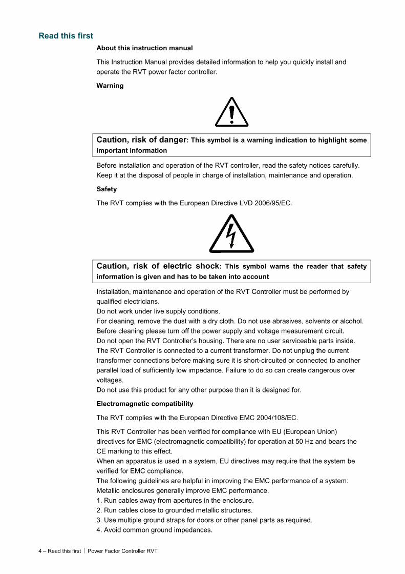
Warning
Caution, risk of danger: This symbol is a warning indication to highlight some
important information
Before installation and operation of the RVT controller, read the safety notices carefully. Keep it at the disposal of people in charge of installation, maintenance and operation.
Safety
The RVT complies with the European Directive LVD 2006/95/EC.
Caution, risk of electric shock: This symbol warns the reader that safety
information is given and has to be taken into account
Installation, maintenance and operation of the RVT Controller must be performed by qualified electricians. Do not work under live supply conditions. For cleaning, remove the dust with a dry cloth. Do not use abrasives, solvents or alcohol. Before cleaning please turn off the power supply and voltage measurement circuit. Do not open the RVT Controller’s housing. There are no user serviceable parts inside. The RVT Controller is connected to a current transformer. Do not unplug the current transformer connections before making sure it is short-circuited or connected to another parallel load of sufficiently low impedance. Failure to do so can create dangerous over voltages. Do not use this product for any other purpose than it is designed for.
Electromagnetic compatibility
The RVT complies with the European Directive EMC 2004/108/EC.
This RVT Controller has been verified for compliance with EU (European Union) directives for EMC (electromagnetic compatibility) for operation at 50 Hz and bears the CE marking to this effect. When an apparatus is used in a system, EU directives may require that the system be verified for EMC compliance. The following guidelines are helpful in improving the EMC performance of a system: Metallic enclosures generally improve EMC performance. 1. Run cables away from apertures in the enclosure. 2. Run cables close to grounded metallic structures. 3. Use multiple ground straps for doors or other panel parts as required. 4. Avoid common ground impedances.
Power Factor Controller RVT Introduction to the controller - 5
1 Introduction to the controller What this chapter contains This chapter gives a general description of the power factor controller RVT. It illustrates
the basic structure of the controller, major features and the touch screen user interface of the controller.
1.1 A powerful fully three phase individual controlled power factor controller The RVT controller is able to fulfill power factor compensation in both balanced and unbalanced network. There are two models for RVT controllers: RVT Base Model RVT6/RVT12 and RVT Three Phase Model RVT12-3P. The Base Model is fully backward compatible to previous RVT controllers with 6 or 12 outputs, which is applicable for a balanced three phases or single phase (phase to phase) network. The Three Phase Model RVT12-3P is a more powerful version with individual phase power factor controlling functions thanks to three CT measurements for each phase. The Three Phase Model RVT12-3P has 12 outputs execution only.
The RVT can also be used for MV automatic capacitor bank. Details on how to connect RVT to a MV bank can be found in 4.2.1.1.
1.2 RVT main features Power factor correction control
The RVT Power Factor Controller is the control unit of an automatic capacitor bank which is used to fulfill reactive power compensation in an installation with prevailing inductive loads. It performs the switching of capacitors in order to reach a user-defined target cos ϕ.
• All the switching parameters may be programmed manually or automatically (description in paragraphs 4.2.2 and 4.2.1)
• In addition to the target cos ϕ, night target cos ϕ and target cos ϕ in regenerative mode may be programmed (description in paragraph 4.2.1.3).
• For the Three Phase Model RVT12-3P, the controller can be configured to switch on/off single phase capacitor in an unbalanced network. This function is used to correct the low power factor in each individual phase; for instances, power factor 0.6 in Phase1, power factor 0.8 in Phase2, power factor 0.95 in Phase3. It is very practical for some residential/commercial area where the three phase loads can be unbalanced due to many single phase loads.
Measurements and monitoring
• Measurements (description in paragraph 4.1).
• Protection against unexpected phenomena and/or unauthorized use (description in paragraphs 3.1.4 and 4.2.1.1.
• Logging of data and alarm messages based on a real time clock (description in paragraphs 4.1.5 and 4.3).
• Checking and testing of relays status (description in paragraphs 4.3.2 and 4.3).
• Temperature measurements: max. 8 temperature probes can be connected in daisy chain connection (description in paragraph 4.2.1.4.3).
6 – Introduction to the controller Power Factor Controller RVT
Communications
• Modbus connection (a Modbus RS485 adapter is required)
• USB connection (Compatible to USB2.0 specifications)
• Ethernet TCP/IP interface
• CAN 2.0 with extended outputs up to 32. Hardware capable in current version RVT, the software is to be implemented in the future.
Detailed information is in paragraph 4.4.
1.3 Front view and rear view
Figure 1: RVT front view
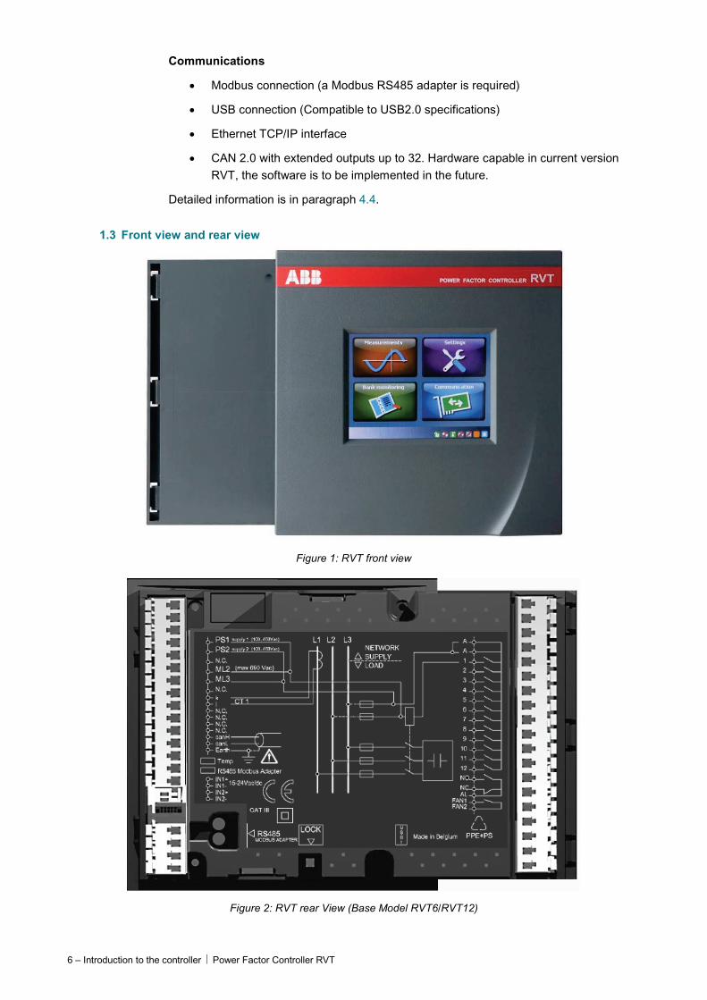
Figure 2: RVT rear View (Base Model RVT6/RVT12)
Power Factor Controller RVT Introduction to the controller - 7
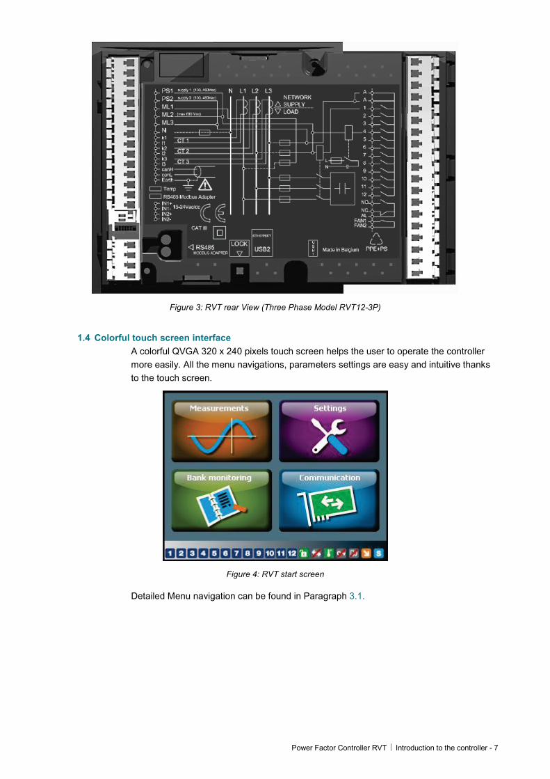
Figure 3: RVT rear View (Three Phase Model RVT12-3P)
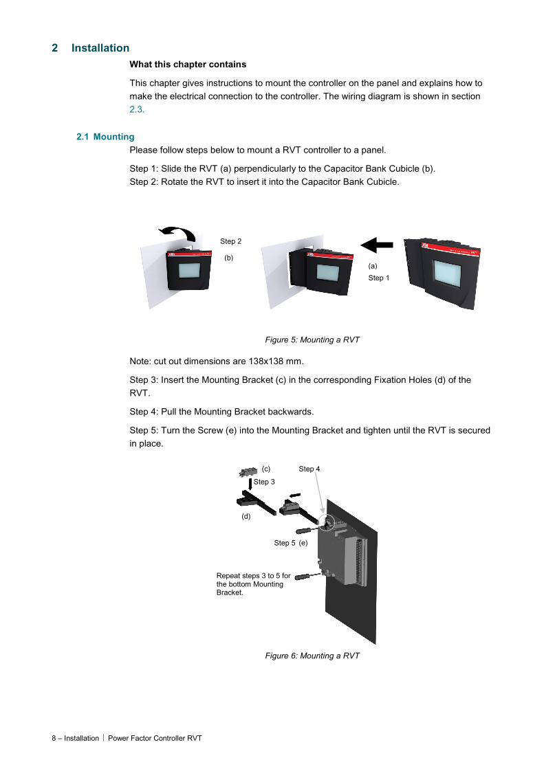
1.4 Colorful touch screen interface A colorful QVGA 320 x 240 pixels touch screen helps the user to operate the controller more easily. All the menu navigations, parameters settings are easy and intuitive thanks to the touch screen.
Figure 4: RVT start screen
Detailed Menu navigation can be found in Paragraph 3.1.
8 – Installation Power Factor Controller RVT
2 Installation What this chapter contains
This chapter gives instructions to mount the controller on the panel and explains how to make the electrical connection to the controller. The wiring diagram is shown in section 2.3.
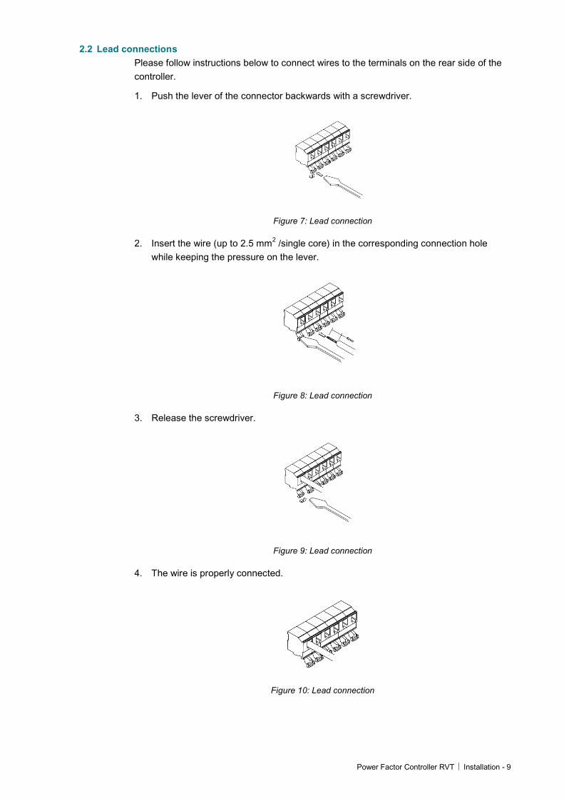
2.1 Mounting Please follow steps below to mount a RVT controller to a panel.
Step 1: Slide the RVT (a) perpendicularly to the Capacitor Bank Cubicle (b). Step 2: Rotate the RVT to insert it into the Capacitor Bank Cubicle.
Step 2
Step 1
(a) (b)
Figure 5: Mounting a RVT
Note: cut out dimensions are 138x138 mm.
Step 3: Insert the Mounting Bracket (c) in the corresponding Fixation Holes (d) of the RVT.
Step 4: Pull the Mounting Bracket backwards.
Step 5: Turn the Screw (e) into the Mounting Bracket and tighten until the RVT is secured in place.
Step 3
Step 4 (c)
(e) Step 5
Repeat steps 3 to 5 for the bottom Mounting Bracket.
(d)
Figure 6: Mounting a RVT
Power Factor Controller RVT Installation - 9
2.2 Lead connections Please follow instructions below to connect wires to the terminals on the rear side of the controller.
1. Push the lever of the connector backwards with a screwdriver.
Figure 7: Lead connection
2. Insert the wire (up to 2.5 mm2 /single core) in the corresponding connection hole while keeping the pressure on the lever.
Figure 8: Lead connection
3. Release the screwdriver.
Figure 9: Lead connection
4. The wire is properly connected.
Figure 10: Lead connection
10 – Installation Power Factor Controller RVT
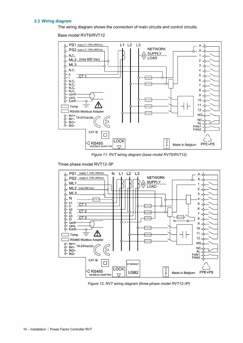
2.3 Wiring diagram The wiring diagram shows the connection of main circuits and control circuits.
Base model RVT6/RVT12
Figure 11: RVT wiring diagram (base model RVT6/RVT12)
Three phase model RVT12-3P
Figure 12: RVT wiring diagram (three-phase model RVT12-3P)
Power Factor Controller RVT Installation - 11
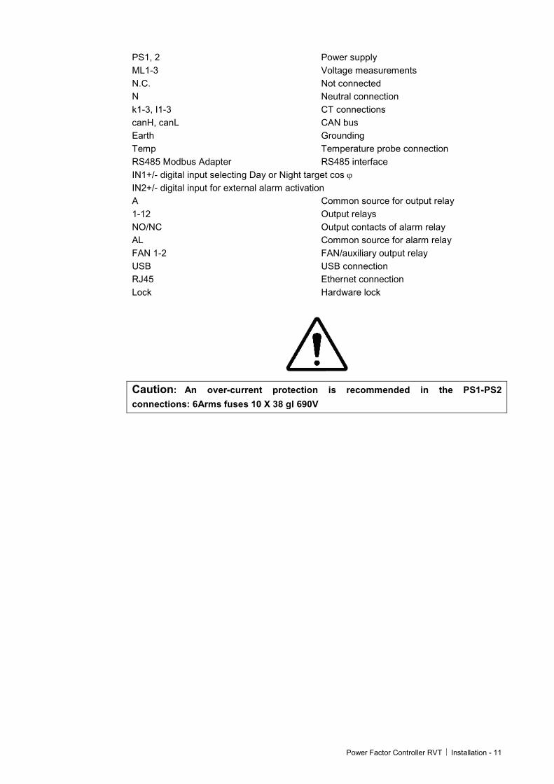
PS1, 2 Power supply ML1-3 Voltage measurements N.C. Not connected N Neutral connection k1-3, I1-3 CT connections canH, canL CAN bus Earth Grounding Temp Temperature probe connection RS485 Modbus Adapter RS485 interface IN1+/- digital input selecting Day or Night target cos ϕ IN2+/- digital input for external alarm activation A Common source for output relay 1-12 Output relays NO/NC Output contacts of alarm relay AL Common source for alarm relay FAN 1-2 FAN/auxiliary output relay USB USB connection RJ45 Ethernet connection Lock Hardware lock
Caution: An over-current protection is recommended in the PS1-PS2
connections: 6Arms fuses 10 X 38 gl 690V

12 – Easy Start Power Factor Controller RVT
3 Easy start What this chapter contains This chapter describes briefly the quick start and automatic commissioning procedure for the controller.
3.1 Menu navigation When the RVT is switched on power after the boot process (where the ABB logo is displayed) the start screen is the first screen which will be displayed as shown in Figure 13.
Figure 13: RVT start screen
In the centre of the screen the four icons (Measurements, Settings, Bank monitoring and Communications) represent the four root-level menu.
At the bottom of the screen, the status bar shows the active capacitor steps, RVT Lock status, warnings, the control source of the RVT(by local touch screen or communications), switching on or off demand, operating mode: A (automatic mode), M (manual mode) and S (setting mode). Detailed meaning of the status icons can be found in following legends.
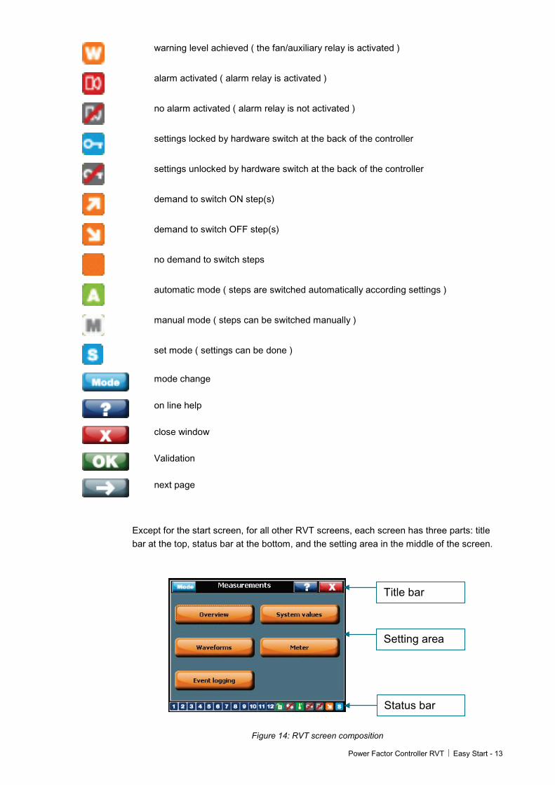
3.1.1 Legends for the touch screen icons
… Active (closed) output ( inactive outputs are not highlighted )
bank settings unlocked
bank settings locked
settings can only be done through the communication
settings can be done through the user interface or the communication
temperature alarm ( alarm relay is activated ) or warning ( fan/auxiliary relay is activated )
no temperature alarm nor warning ( alarm and fan/auxiliary relays are not activated )
Power Factor Controller RVT Easy Start - 13
warning level achieved ( the fan/auxiliary relay is activated )
alarm activated ( alarm relay is activated )
no alarm activated ( alarm relay is not activated )
settings locked by hardware switch at the back of the controller
settings unlocked by hardware switch at the back of the controller
demand to switch ON step(s)
demand to switch OFF step(s)
no demand to switch steps
automatic mode ( steps are switched automatically according settings )
manual mode ( steps can be switched manually )
set mode ( settings can be done )
mode change
on line help
close window
Validation
next page
Except for the start screen, for all other RVT screens, each screen has three parts: title bar at the top, status bar at the bottom, and the setting area in the middle of the screen.
Title bar
Setting area
Status bar
Figure 14: RVT screen composition
14 – Easy Start Power Factor Controller RVT
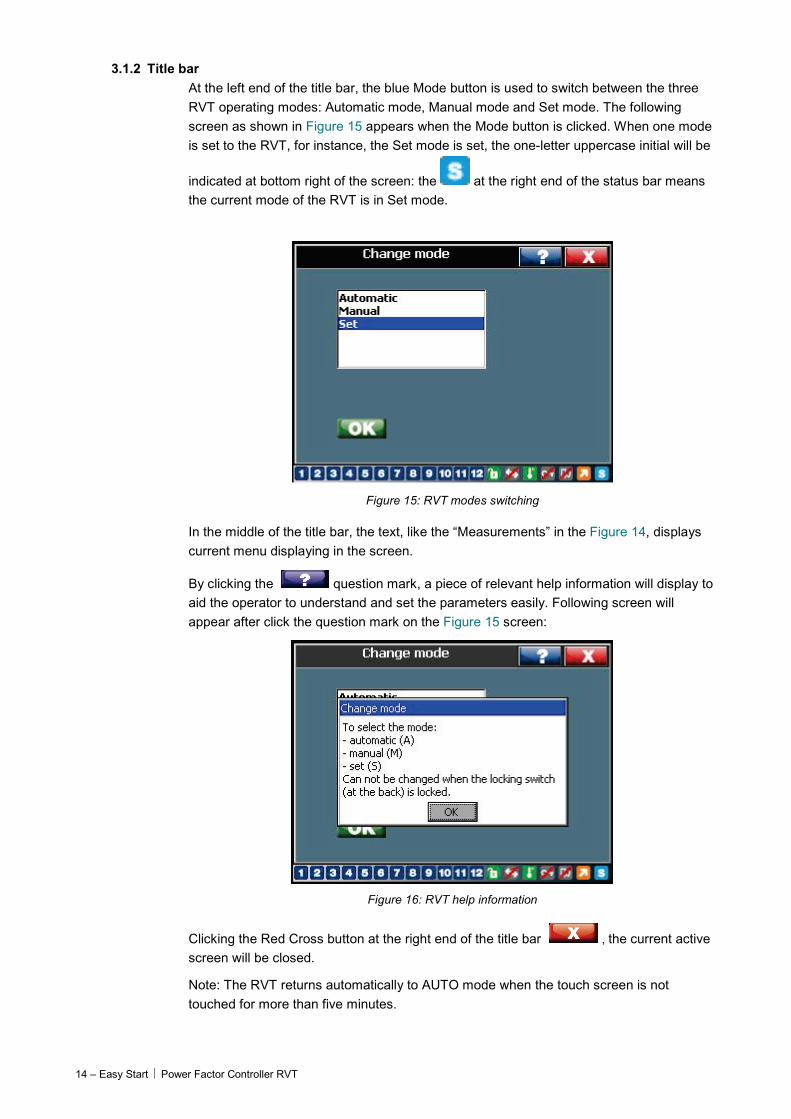
3.1.2 Title bar At the left end of the title bar, the blue Mode button is used to switch between the three RVT operating modes: Automatic mode, Manual mode and Set mode. The following screen as shown in Figure 15 appears when the Mode button is clicked. When one mode is set to the RVT, for instance, the Set mode is set, the one-letter uppercase initial will be
indicated at bottom right of the screen: the at the right end of the status bar means the current mode of the RVT is in Set mode.
Figure 15: RVT modes switching
In the middle of the title bar, the text, like the “Measurements” in the Figure 14, displays current menu displaying in the screen.
By clicking the question mark, a piece of relevant help information will display to aid the operator to understand and set the parameters easily. Following screen will appear after click the question mark on the Figure 15 screen:
Figure 16: RVT help information
Clicking the Red Cross button at the right end of the title bar , the current active screen will be closed.
Note: The RVT returns automatically to AUTO mode when the touch screen is not touched for more than five minutes.
Power Factor Controller RVT Easy Start - 15
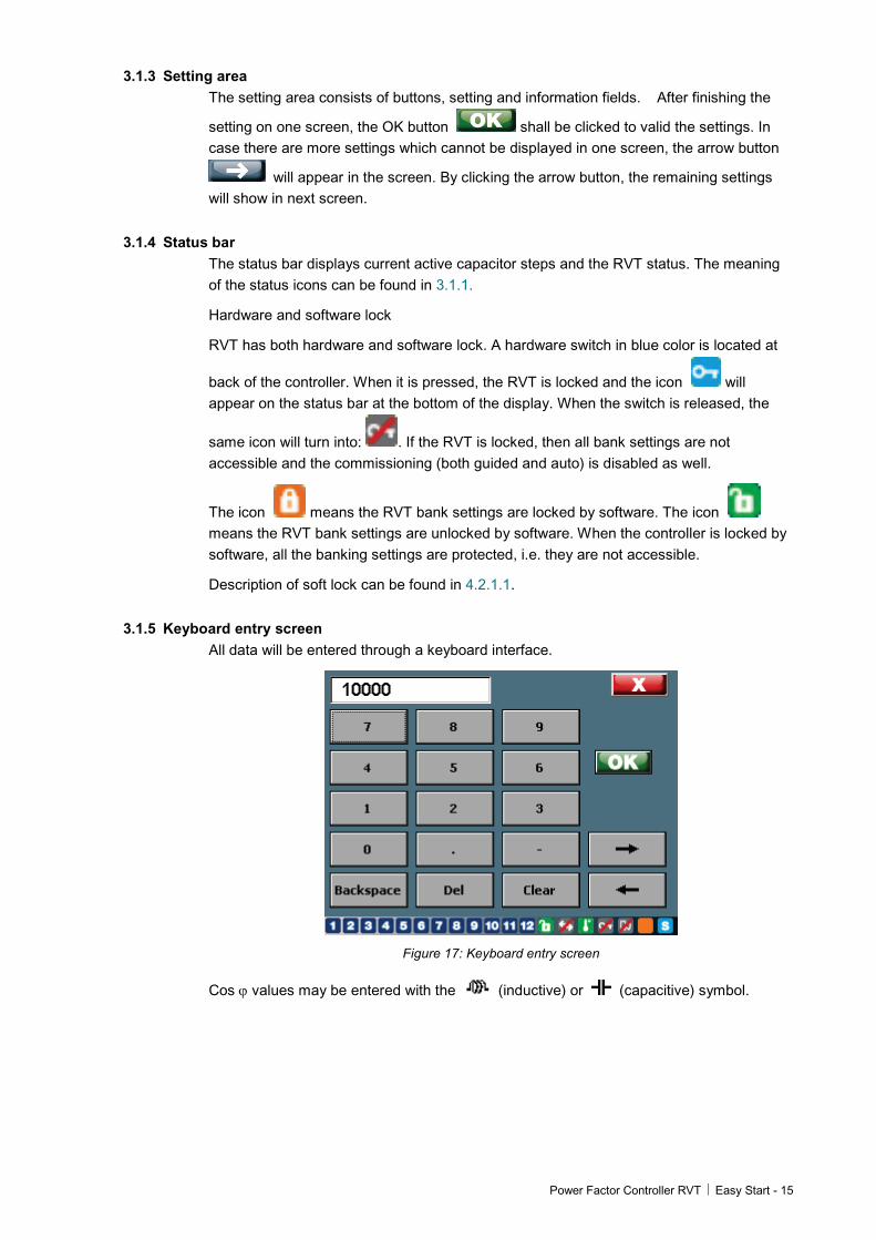
3.1.3 Setting area The setting area consists of buttons, setting and information fields. After finishing the
setting on one screen, the OK button shall be clicked to valid the settings. In case there are more settings which cannot be displayed in one screen, the arrow button
will appear in the screen. By clicking the arrow button, the remaining settings will show in next screen.
3.1.4 Status bar The status bar displays current active capacitor steps and the RVT status. The meaning of the status icons can be found in 3.1.1.
Hardware and software lock
RVT has both hardware and software lock. A hardware switch in blue color is located at
back of the controller. When it is pressed, the RVT is locked and the icon will appear on the status bar at the bottom of the display. When the switch is released, the
same icon will turn into: . If the RVT is locked, then all bank settings are not accessible and the commissioning (both guided and auto) is disabled as well.
The icon means the RVT bank settings are locked by software. The icon means the RVT bank settings are unlocked by software. When the controller is locked by software, all the banking settings are protected, i.e. they are not accessible.
Description of soft lock can be found in 4.2.1.1.
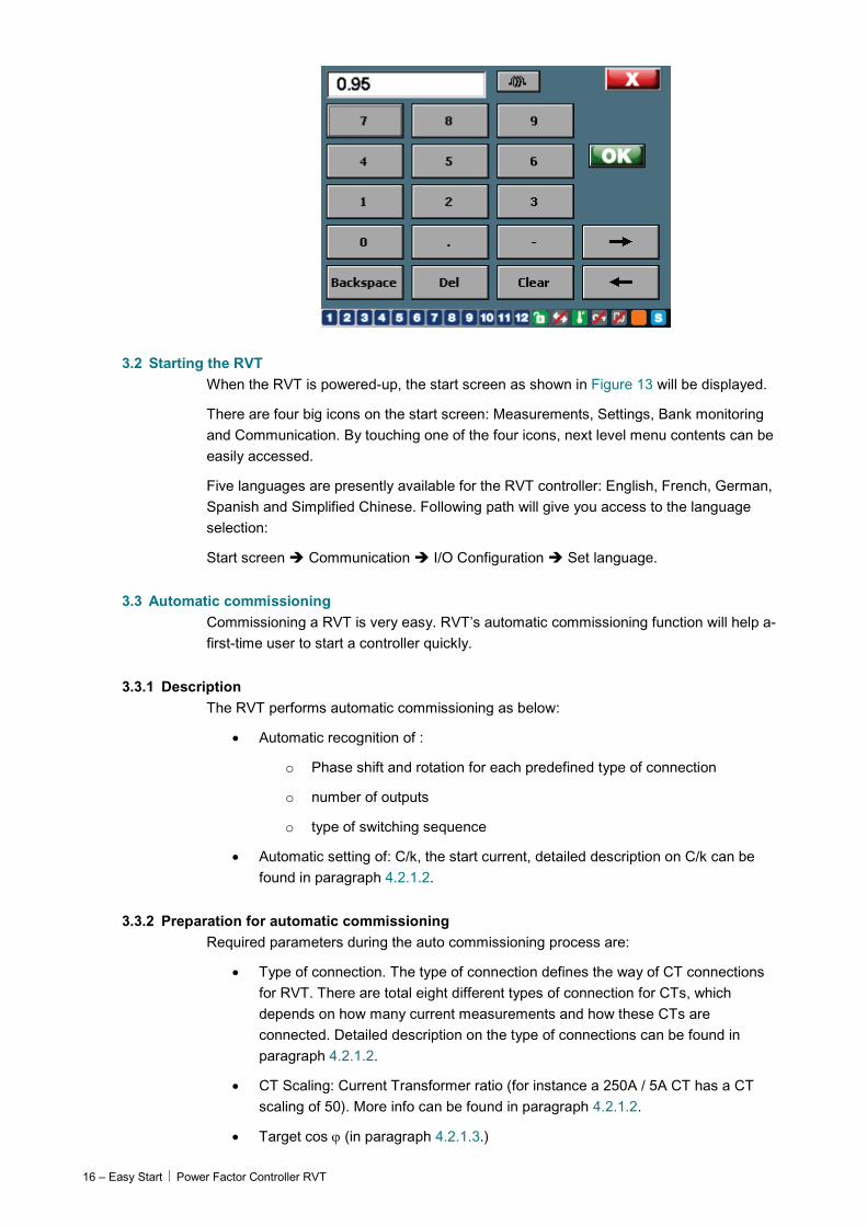
3.1.5 Keyboard entry screen All data will be entered through a keyboard interface.
Figure 17: Keyboard entry screen
Cos ϕ values may be entered with the (inductive) or (capacitive) symbol.
16 – Easy Start Power Factor Controller RVT
3.2 Starting the RVT When the RVT is powered-up, the start screen as shown in Figure 13 will be displayed.
There are four big icons on the start screen: Measurements, Settings, Bank monitoring and Communication. By touching one of the four icons, next level menu contents can be easily accessed.
Five languages are presently available for the RVT controller: English, French, German, Spanish and Simplified Chinese. Following path will give you access to the language selection:
Start screen Communication I/O Configuration Set language.
3.3 Automatic commissioning Commissioning a RVT is very easy. RVT’s automatic commissioning function will help a-first-time user to start a controller quickly.
3.3.1 Description The RVT performs automatic commissioning as below:
• Automatic recognition of :
o Phase shift and rotation for each predefined type of connection
o number of outputs
o type of switching sequence
• Automatic setting of: C/k, the start current, detailed description on C/k can be found in paragraph 4.2.1.2.
3.3.2 Preparation for automatic commissioning Required parameters during the auto commissioning process are:
• Type of connection. The type of connection defines the way of CT connections for RVT. There are total eight different types of connection for CTs, which depends on how many current measurements and how these CTs are connected. Detailed description on the type of connections can be found in paragraph 4.2.1.2.
• CT Scaling: Current Transformer ratio (for instance a 250A / 5A CT has a CT scaling of 50). More info can be found in paragraph 4.2.1.2.
• Target cos ϕ (in paragraph 4.2.1.3.)
Power Factor Controller RVT Easy Start - 17
3.3.3 Automatic commissioning
• if you have a short-circuit on the CT’s secondary winding do not forget to open it after having connected the current input of the PF Controller
• if a transformer is used for the voltage measurement, the Vscaling value needs to be changed accordingly (see paragraph 4.2.1.)
Notes: when the icon (hardware lock) appears on the status bar at the bottom of the display, this means that the RVT is locked. The set Mode access is denied and commissioning cannot be performed until the RVT is unlocked (see description in paragraph 4.2.1.1.)
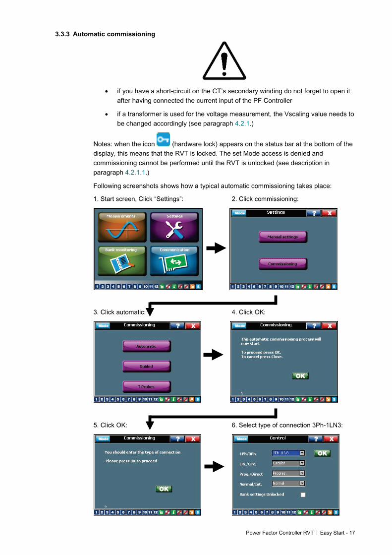
Following screenshots shows how a typical automatic commissioning takes place:
1. Start screen, Click “Settings”: 2. Click commissioning:
3. Click automatic: 4. Click OK:
5. Click OK: 6. Select type of connection 3Ph-1LN3:
18 – Easy Start Power Factor Controller RVT
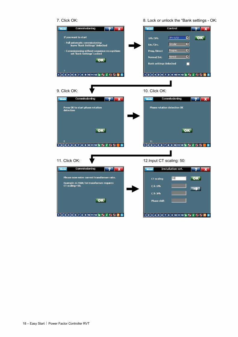
7. Click OK: 8. Lock or unlock the “Bank settings - OK:
9. Click OK: 10. Click OK:
11. Click OK: 12.Input CT scaling: 50:
Power Factor Controller RVT Easy Start - 19
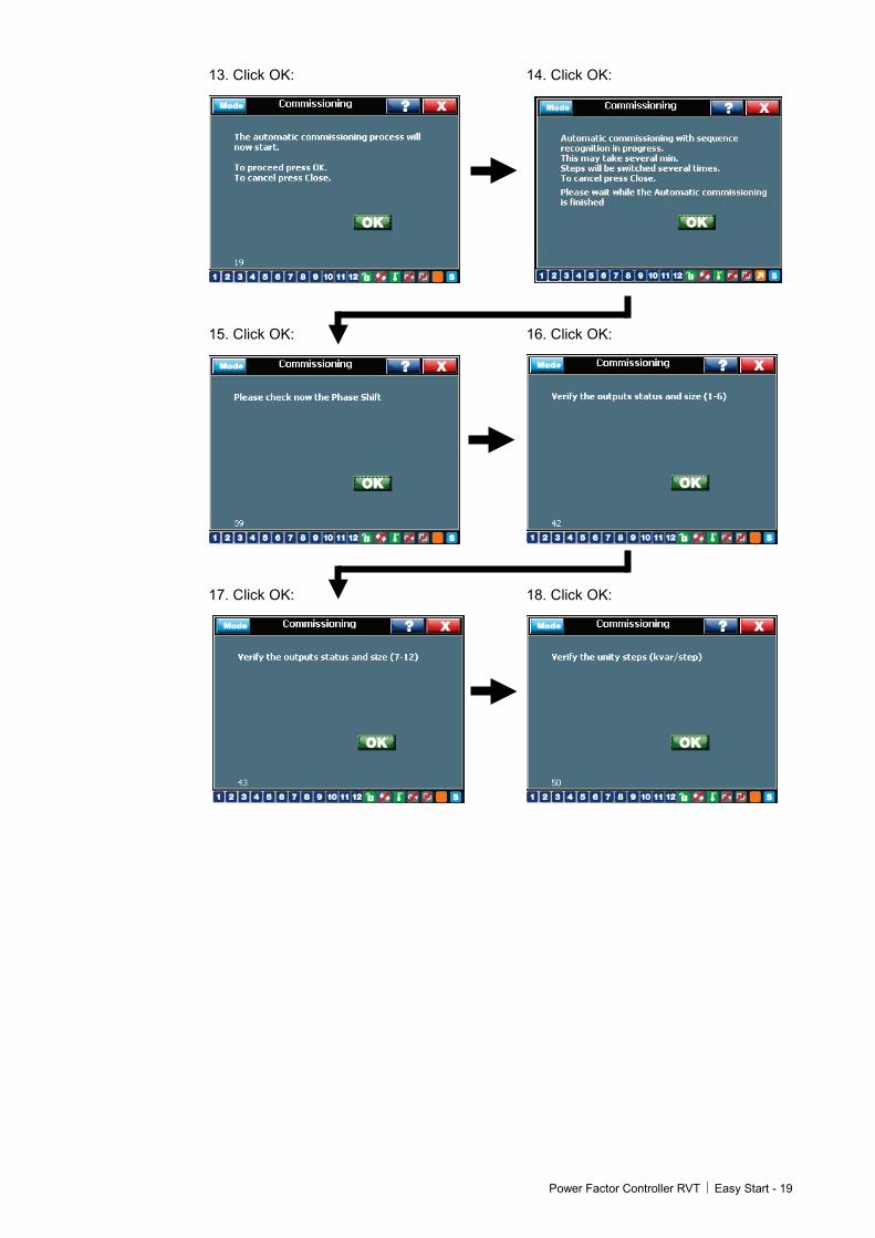
13. Click OK: 14. Click OK:
15. Click OK: 16. Click OK:
17. Click OK: 18. Click OK:
20 – Easy Start Power Factor Controller RVT
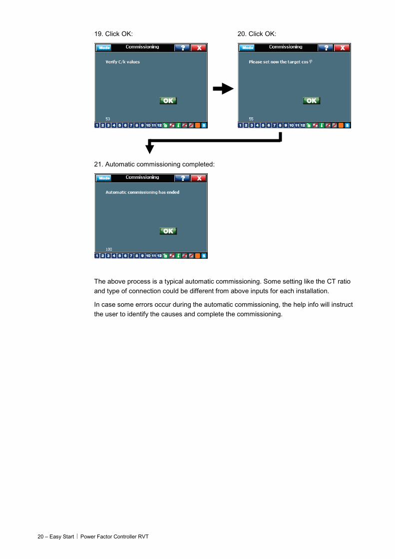
19. Click OK: 20. Click OK:
21. Automatic commissioning completed:
The above process is a typical automatic commissioning. Some setting like the CT ratio and type of connection could be different from above inputs for each installation.
In case some errors occur during the automatic commissioning, the help info will instruct the user to identify the causes and complete the commissioning.
Power Factor Controller RVT Measurements and Settings - 21
4 Measurements and Settings What this chapter contains This chapter describes all the menus/submenus for measurements, settings, bank monitoring and communications settings, etc.
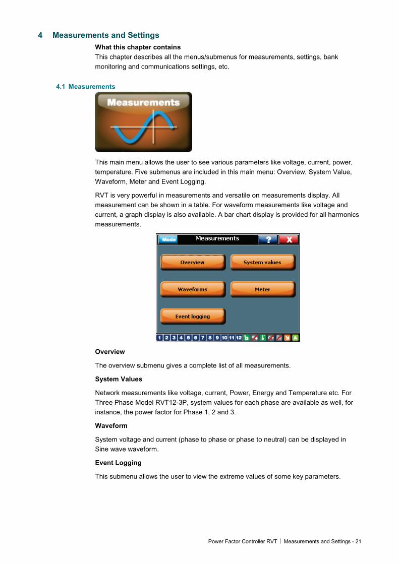
4.1 Measurements
This main menu allows the user to see various parameters like voltage, current, power, temperature. Five submenus are included in this main menu: Overview, System Value, Waveform, Meter and Event Logging.
RVT is very powerful in measurements and versatile on measurements display. All measurement can be shown in a table. For waveform measurements like voltage and current, a graph display is also available. A bar chart display is provided for all harmonics measurements.
Overview
The overview submenu gives a complete list of all measurements.
System Values
Network measurements like voltage, current, Power, Energy and Temperature etc. For Three Phase Model RVT12-3P, system values for each phase are available as well, for instance, the power factor for Phase 1, 2 and 3.
Waveform
System voltage and current (phase to phase or phase to neutral) can be displayed in Sine wave waveform.
Event Logging
This submenu allows the user to view the extreme values of some key parameters.

22 – Measurements and Settings Power Factor Controller RVT
Meter
This function offers a possibility for the user to display three most concerned measurements in one screen. For instance, three line voltages can be shown in one screen in a better resolution and better view. Detailed instructions for this function can be found in 4.1.4.
4.1.1 Overview Details on all available measurements through RVT:
Table 1: Measurements overview
Designation Unit Description
Voltage Range Accuracy Max value
Vrms V Rms Voltage Up to 690Vac ± 1 % 106 V
V1 V Rms voltage at the fundamental frequency
Up to 690Vac ± 1 % 106 V
Frequency Hz Fundamental voltage frequency
45Hz - 65Hz ± 0.5% 45Hz - 75 Hz
THDV % Total harmonic voltage distortion on voltage
0 - 300% ± 1 % 1000 %
V harm. Table Voltage harmonics displayed in a table
2nd-49th See later in this paragraph
V harm. chart Voltage harmonics displayed in a bar graph
2nd-49th See later in this paragraph
Current Range Accuracy Max value
Irms A Rms Current 0 - 5 A ± 1 % 106 A
I1 A Rms current at the fundamental frequency
0 - 5 A ± 1 % 106 A
THDI % Total harmonic current distortion on current
0 - 300% ± 1 % 1000%
I harm. table Current harmonics displayed in a table
2nd-49th See later in this paragraph
I harm. chart Current harmonics displayed in a bar graph
2nd-49th See later in this paragraph
Power Range Accuracy Max value
Cos ϕ Displacement power factor -1 +1 ± 0.02 -1 +1
PF Power factor -1 +1 ± 0.02 -1 +1
P W Active power -109 109 W ± 2% -109 109 W
Q var Reactive power -109 109 var ± 2% -109 109 var
S VA Apparent power 0 109 VA ± 2% 0 109 VA
Missing Q var Missing power to reach the pre-set alarm cos ϕ
0 109 var ± 2% 0 109 var
Missing Steps Missing capacitor steps to reach the pre-set alarm cos ϕ
Power Factor Controller RVT Measurements and Settings - 23
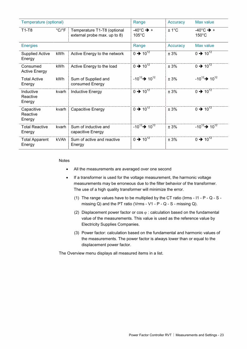
Temperature (optional) Range Accuracy Max value
T1-T8 °C/°F Temperature T1-T8 (optional external probe max. up to 8)
-40°C + 105°C
± 1°C -40°C + 150°C
Energies Range Accuracy Max value
Supplied Active Energy
kWh Active Energy to the network 0 1012 ± 3% 0 1012
Consumed Active Energy
kWh Active Energy to the load 0 1012 ± 3% 0 1012
Total Active Energy
kWh Sum of Supplied and consumed Energy
-1012 1012 ± 3% -1012 1012
Inductive Reactive Energy
kvarh Inductive Energy 0 1012 ± 3% 0 1012
Capacitive Reactive Energy
kvarh Capacitive Energy 0 1012 ± 3% 0 1012
Total Reactive Energy
kvarh Sum of inductive and capacitive Energy
-1012 1012 ± 3% -1012 1012
Total Apparent Energy
kVAh Sum of active and reactive Energy
0 1012 ± 3% 0 1012
Notes
• All the measurements are averaged over one second
• If a transformer is used for the voltage measurement, the harmonic voltage measurements may be erroneous due to the filter behavior of the transformer. The use of a high quality transformer will minimize the error.
(1) The range values have to be multiplied by the CT ratio (Irms - I1 - P - Q - S - missing Q) and the PT ratio (Vrms - V1 - P - Q - S - missing Q).
(2) Displacement power factor or cos ϕ : calculation based on the fundamental value of the measurements. This value is used as the reference value by Electricity Supplies Companies.
(3) Power factor: calculation based on the fundamental and harmonic values of the measurements. The power factor is always lower than or equal to the displacement power factor.
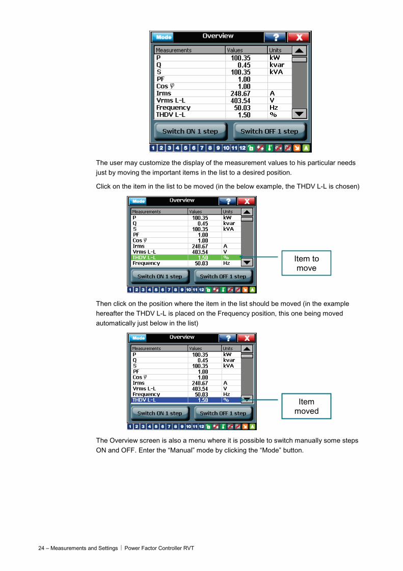
The Overview menu displays all measured items in a list.
24 – Measurements and Settings Power Factor Controller RVT
The user may customize the display of the measurement values to his particular needs just by moving the important items in the list to a desired position.
Click on the item in the list to be moved (in the below example, the THDV L-L is chosen)
Item to move
Then click on the position where the item in the list should be moved (in the example hereafter the THDV L-L is placed on the Frequency position, this one being moved automatically just below in the list)
Item moved
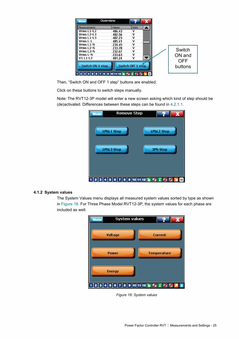
The Overview screen is also a menu where it is possible to switch manually some steps ON and OFF. Enter the “Manual” mode by clicking the “Mode” button.
Power Factor Controller RVT Measurements and Settings - 25
Switch ON and
OFF buttons
Then, “Switch ON and OFF 1 step” buttons are enabled.
Click on these buttons to switch steps manually.
Note: The RVT12-3P model will enter a new screen asking which kind of step should be (de)activated. Differences between these steps can be found in 4.2.1.1.
4.1.2 System values The System Values menu displays all measured system values sorted by type as shown in Figure 18. For Three Phase Model RVT12-3P, the system values for each phase are included as well.
Figure 18: System values

26 – Measurements and Settings Power Factor Controller RVT
Voltage (current) measurements
Display harmonic
Voltage (current) harmonic chart and table
Harmonics voltage/current can be illustrated in bar chart as shown below. A scrolling bar is to choose a specific harmonic to display at the top of the screen: the harmonic order, the value and percentage against Fundamental.
For voltage and current values, the RVT is able to display the harmonics voltage and currents in table or in spectrum. Click on the “Select” button to choose which measurement is displayed in the harmonic table or chart.
Select measurement
to display
Zoom in / out the chart
Figure 19: Harmonics voltage in chart
Power Factor Controller RVT Measurements and Settings - 27
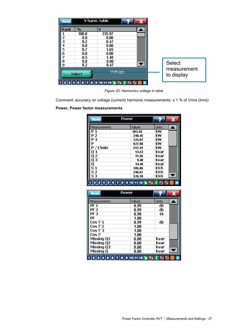
Select measurement to display
Figure 20: Harmonics voltage in table
Comment: accuracy on voltage (current) harmonic measurements: ± 1 % of Vrms (Irms)
Power, Power factor measurements

28 – Measurements and Settings Power Factor Controller RVT
Temperature measurements
Energy measurements
Reset energy values
Energy measurements are only available on the RVT12-3P (the 3 phase model is equipped with a real time clock).
Energy values may be “Reset” to 0.
4.1.3 Waveform Available voltage and current signals (depending on RVT type and connection used) and the line current can be displayed on the screen as waveforms. Figure 21 shows the voltage wave form between line and neutral.
Select waveforms
Figure 21: Voltage and current waveforms
Power Factor Controller RVT Measurements and Settings - 29
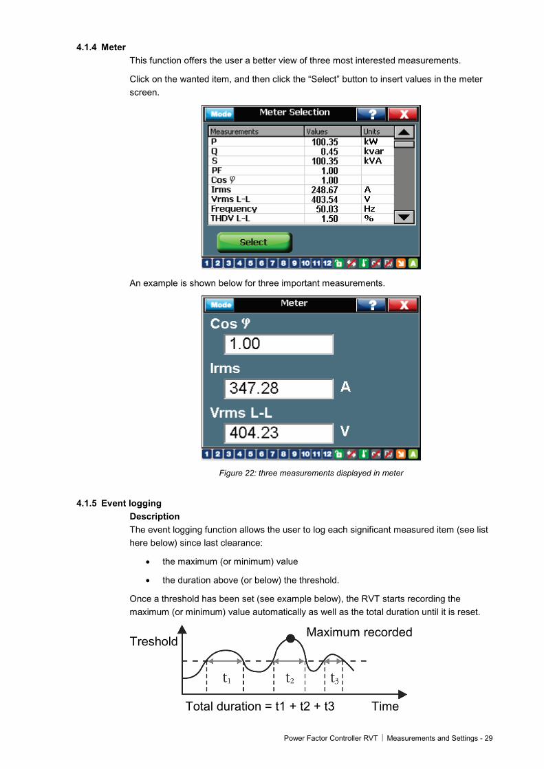
4.1.4 Meter This function offers the user a better view of three most interested measurements.
Click on the wanted item, and then click the “Select” button to insert values in the meter screen.
An example is shown below for three important measurements.
Figure 22: three measurements displayed in meter
4.1.5 Event logging Description The event logging function allows the user to log each significant measured item (see list here below) since last clearance:
• the maximum (or minimum) value
• the duration above (or below) the threshold.
Once a threshold has been set (see example below), the RVT starts recording the maximum (or minimum) value automatically as well as the total duration until it is reset.
Treshold Maximum recorded
Total duration = t1 + t2 + t3 Time

30 – Measurements and Settings Power Factor Controller RVT
Recorded values The event logging function allows the user to record the time during which a measured value exceeds a threshold and its maximum value for the following parameters : Vrms [V], Irms [A], P [kW], Q [kvar], S [kVA], THDV [%], THDI [%], missing Q [kvar], frequency* [Hz], T1* [°C or °F] to T8* [°C or °F]. * Minimum values and duration below a threshold are also recorded for the frequency and the temperatures.
Figure 23: Event logging recorded values
Example Recording of information on Vrms. Voltage network : 400V.
Figure 24: Event logging threshold setting - Vrms
Power Factor Controller RVT Measurements and Settings - 31
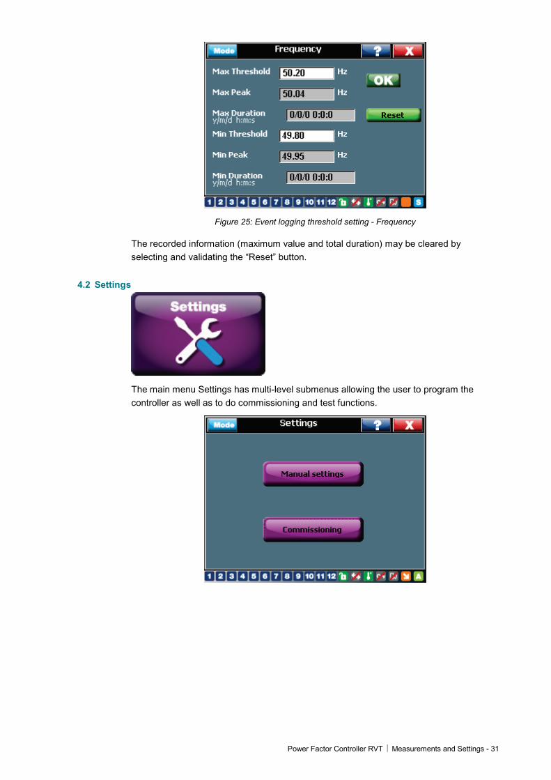
Figure 25: Event logging threshold setting - Frequency
The recorded information (maximum value and total duration) may be cleared by selecting and validating the “Reset” button.
4.2 Settings
The main menu Settings has multi-level submenus allowing the user to program the controller as well as to do commissioning and test functions.

32 – Measurements and Settings Power Factor Controller RVT
4.2.1 Manual settings (Set Mode) The manual settings allow the user to access all the Bank, Installation, User settings and protection/warning configurations. The user can also restore the factory setting from this sub-menu.
Figure 26: Manual settings
Before making any settings to the controller, please make it is in Set mode. Please refer to 3.1.4 and 4.2.1.1. for the controller mode setting and locking/unlocking.
4.2.1.1 Bank settings start->settings->manual settings->bank settings
The Bank Settings menu includes all configuration parameters related to the bank.
Power factor control settings
Delays settings
Outputs selection and
settings
Figure 27: Bank setting
Following shows the list of bank setting parameters.
V nominal: nominal bank voltage.
When a V nominal value is entered, under-voltage and overvoltage protection levels are automatically set at 80% and 120% of V nominal.
These level values can be changed manually.
V scaling: external voltage transformer ratio.
Power Factor Controller RVT Measurements and Settings - 33
Examples: for a 15kV/100V voltage transformer, V scaling = 150.
if no external voltage transformer is used, V scaling = 1.
This function enables the RVT to control a MV capacitor bank. A proper voltage transformer shall be connected to the measurements terminals of RVT. Then the RVT will display the MV measurement values accordingly.
Q step 1ph: the smallest step size for single phase (phase to neutral) capacitors which are used for individual phase power factor correction in an unbalanced network.
Q step 3ph: the smallest step size for three phase capacitors in a balanced network.
For the above two settings,
a) After automatic commissioning, this value will be set according to the smallest step in the capacitor bank.
b) For guided commissioning (see 4.2.2.2), this value need to be set manually.
Here is an example in a capacitor bank which has both individual phase (3 steps) and three-phase (3 steps) power factor correction:
Single phase sequence*: 1 ( 5kvar) 2 (10kvar) 2 (10kvar) Q step 1ph = 5 kvar
Three phase sequence: 1 (10kvar) 2 (20kvar) 2 (20kvar) Q step 3ph = 10 kvar
Or,
Three phase sequence: 2 (15kvar) 4 (30kvar) 5 (37.5kvar) Q step = 7.5 kvar
*Sequence: relative reactive power value of the capacitors connected to the RVT outputs. These relative values are included between 0 and 8.
For both Base Model RVT6/RVT12 and Three Phase Model RVT12-3P, the default factory sequence is: 1:1:….:1. Customized sequence may be introduced manually.
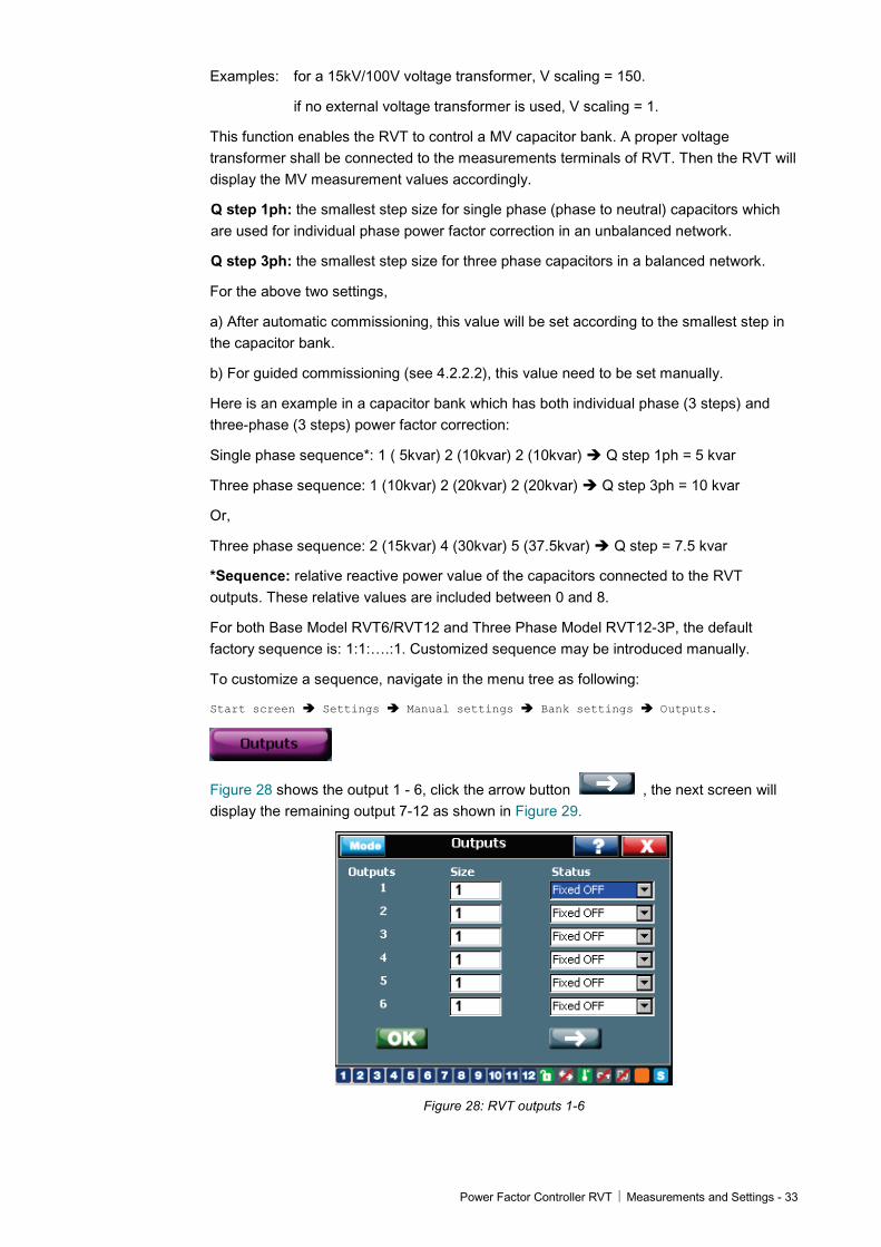
To customize a sequence, navigate in the menu tree as following:
Start screen Settings Manual settings Bank settings Outputs.
Figure 28 shows the output 1 - 6, click the arrow button , the next screen will display the remaining output 7-12 as shown in Figure 29.
Figure 28: RVT outputs 1-6

34 – Measurements and Settings Power Factor Controller RVT
Figure 29: RVT outputs 7-12 (Three phase model RVT12-3P)
On the right of the screen, the “Status” includes six attributes of each output:
“Fixed OFF”: this output is disabled (default factory setting);
“Fixed ON”: this output is enabled (the corresponding capacitor is always connected);
“1PhL1, 1Phl2, 1PhL3”: this output controls a phase to neutral capacitor, which is at phase 1, 2 or 3 respectively.
“3Ph”: this output controls a 3 phase capacitor.
For a Base Model RVT6/RVT12, only “Fixed OFF, Fixed ON and Enabled” are available for the output status. An output need to be set “Enabled” before the controller switches on or off a capacitor.
Some typical outputs setting for Three Phase Model RVT12-3P:
Typical setting one: 12 steps of single phase (phase to neutral) capacitors:
Figure 30: Typical outputs setting 12 x 1ph (Three phase model RVT12-3P)
Typical setting two: 6 steps of three phase capacitors + 6 steps of single phase (phase to neutral) capacitors:
Power Factor Controller RVT Measurements and Settings - 35
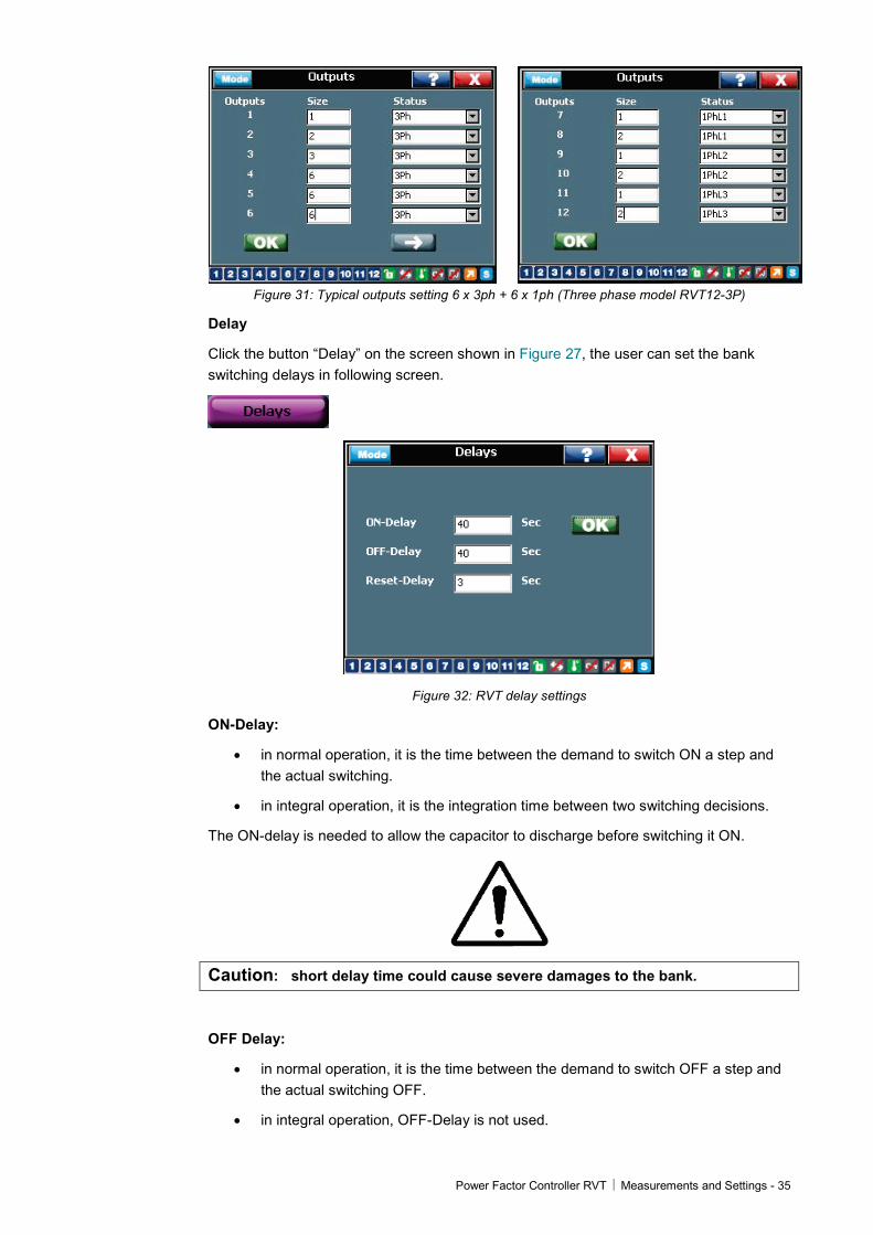
Figure 31: Typical outputs setting 6 x 3ph + 6 x 1ph (Three phase model RVT12-3P)
Delay
Click the button “Delay” on the screen shown in Figure 27, the user can set the bank switching delays in following screen.
Figure 32: RVT delay settings
ON-Delay:
• in normal operation, it is the time between the demand to switch ON a step and the actual switching.
• in integral operation, it is the integration time between two switching decisions.
The ON-delay is needed to allow the capacitor to discharge before switching it ON.
Caution: short delay time could cause severe damages to the bank.
OFF Delay:
• in normal operation, it is the time between the demand to switch OFF a step and the actual switching OFF.
• in integral operation, OFF-Delay is not used.
36 – Measurements and Settings Power Factor Controller RVT
Reset Delay: the time the RVT waits before restarting bank operation after a power outage.
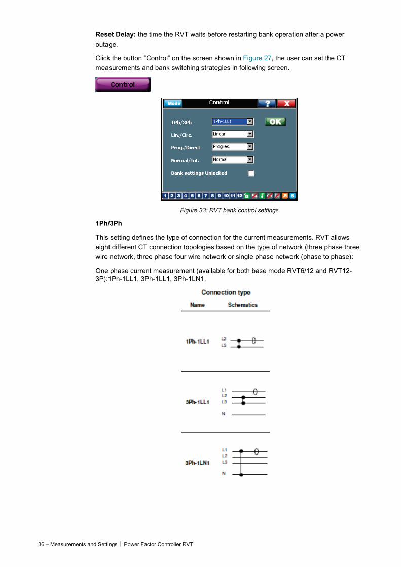
Click the button “Control” on the screen shown in Figure 27, the user can set the CT measurements and bank switching strategies in following screen.
Figure 33: RVT bank control settings
1Ph/3Ph
This setting defines the type of connection for the current measurements. RVT allows eight different CT connection topologies based on the type of network (three phase three wire network, three phase four wire network or single phase network (phase to phase):
One phase current measurement (available for both base mode RVT6/12 and RVT12-3P):1Ph-1LL1, 3Ph-1LL1, 3Ph-1LN1,
Power Factor Controller RVT Measurements and Settings - 37
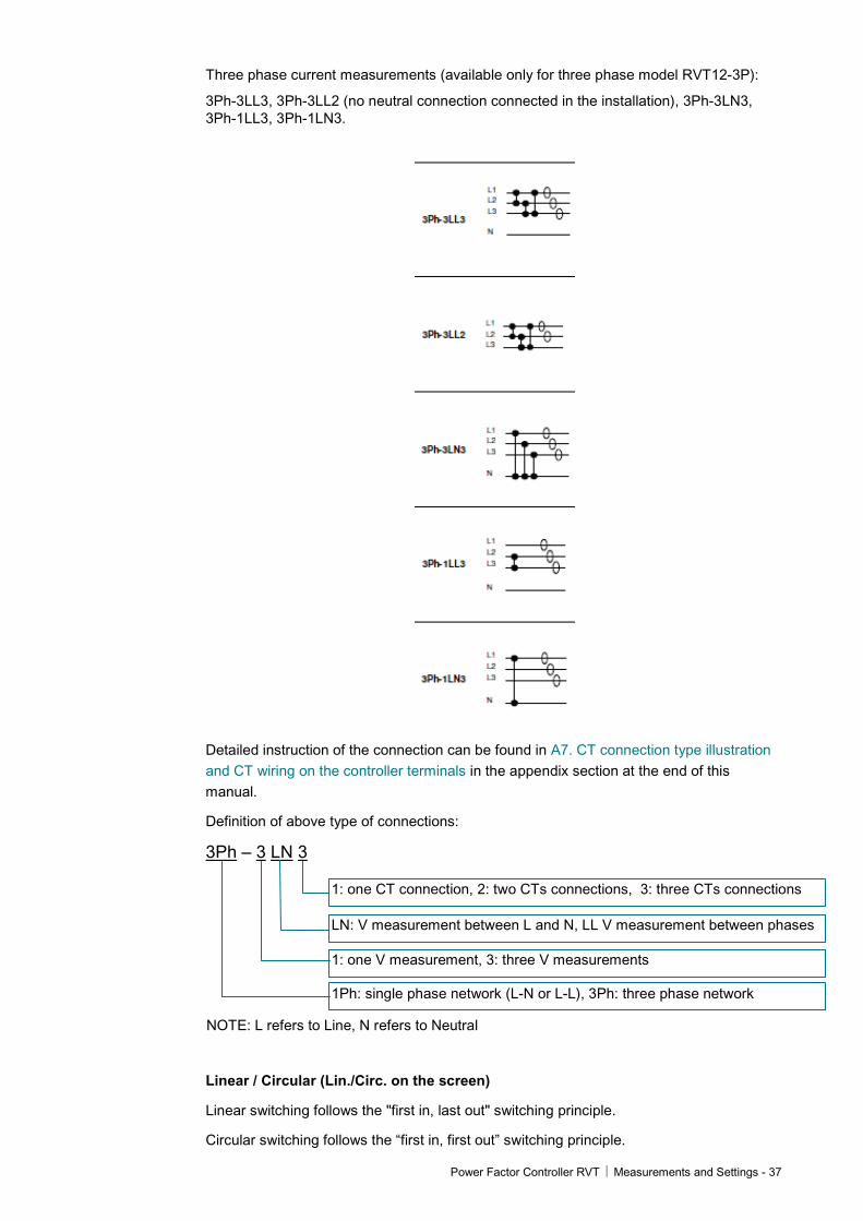
Three phase current measurements (available only for three phase model RVT12-3P):
3Ph-3LL3, 3Ph-3LL2 (no neutral connection connected in the installation), 3Ph-3LN3, 3Ph-1LL3, 3Ph-1LN3.
Detailed instruction of the connection can be found in A7. CT connection type illustration and CT wiring on the controller terminals in the appendix section at the end of this manual.
Definition of above type of connections:
3Ph – 3 LN 3
1: one CT connection, 2: two CTs connections, 3: three CTs connections
LN: V measurement between L and N, LL V measurement between phases
1: one V measurement, 3: three V measurements
1Ph: single phase network (L-N or L-L), 3Ph: three phase network
NOTE: L refers to Line, N refers to Neutral
Linear / Circular (Lin./Circ. on the screen)
Linear switching follows the "first in, last out" switching principle.
Circular switching follows the “first in, first out” switching principle.

38 – Measurements and Settings Power Factor Controller RVT
Both operations are described in the following table.
Circular switching increases the lifetime of capacitors and contactors by balancing the stress among all the outputs.
In case of “double first step” (1:1:2:2:…, 1:1:2:4:4.,…), the circularity applies to the first two outputs and also on the outputs of higher value.
Linear
Circular
Demand for adding a step Demand for removing a step Output closed Output open
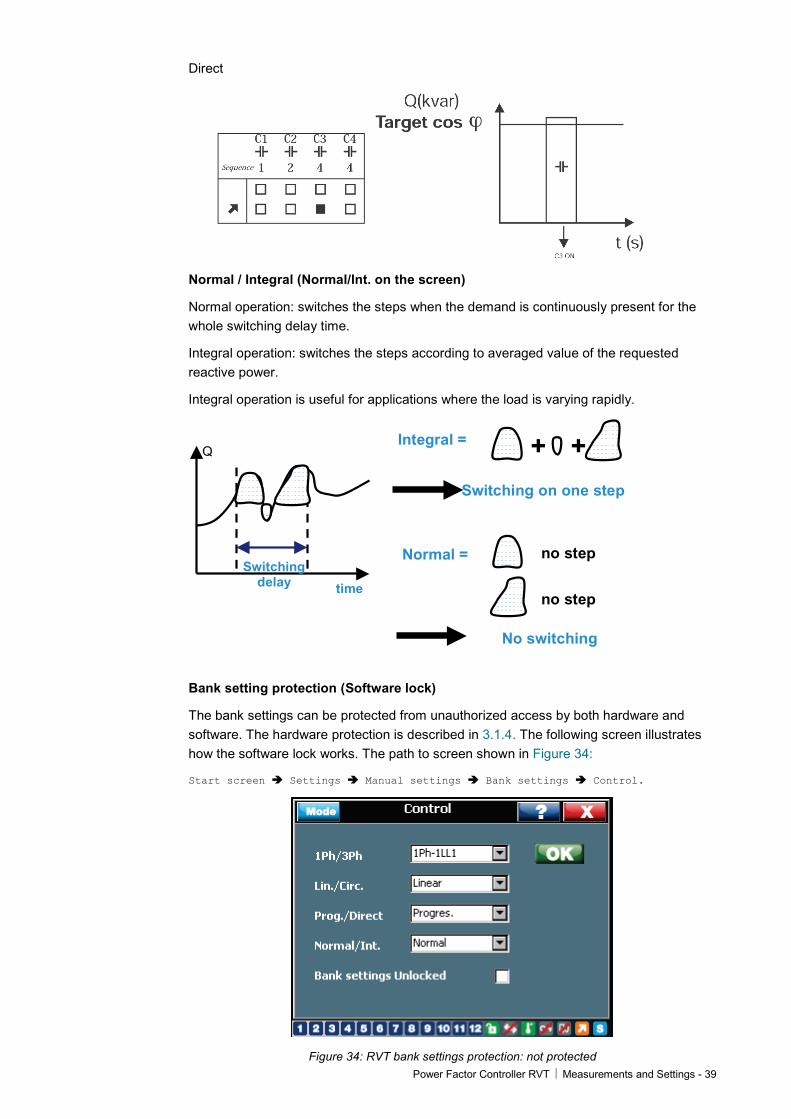
Progressive / Direct (Prog./Direct on the screen)
Progressive operation switches the steps sequentially one by one, based on ON-Delay value.
Direct operation switches the biggest steps first then the other steps with a fixed delay of 12s, to reach the target cos ϕ faster.
The direct mode allows avoiding many useless intermediary switchings.
Progressive
Power Factor Controller RVT Measurements and Settings - 39
Direct
Normal / Integral (Normal/Int. on the screen)
Normal operation: switches the steps when the demand is continuously present for the whole switching delay time.
Integral operation: switches the steps according to averaged value of the requested reactive power.
Integral operation is useful for applications where the load is varying rapidly.
time
Switching delay
Integral = + +
Switching on one step
Normal =
No switching
no step
no step
Q
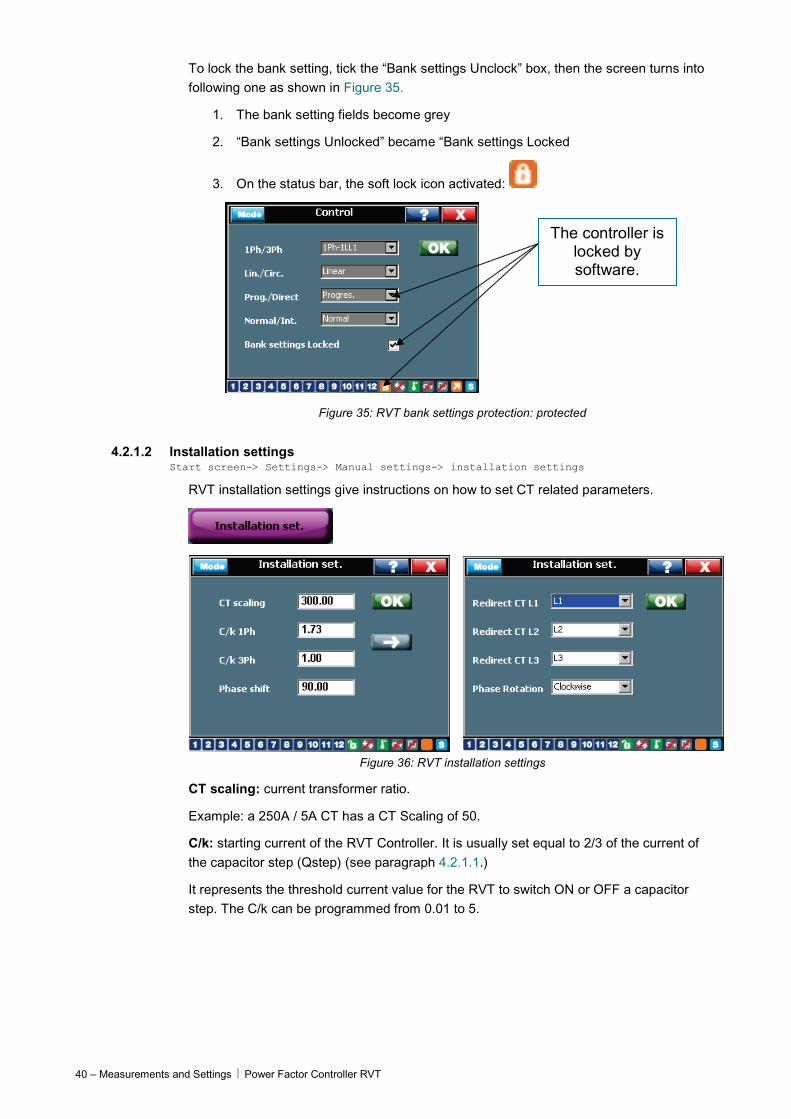
Bank setting protection (Software lock)
The bank settings can be protected from unauthorized access by both hardware and software. The hardware protection is described in 3.1.4. The following screen illustrates how the software lock works. The path to screen shown in Figure 34:
Start screen Settings Manual settings Bank settings Control.
Figure 34: RVT bank settings protection: not protected
40 – Measurements and Settings Power Factor Controller RVT
To lock the bank setting, tick the “Bank settings Unclock” box, then the screen turns into following one as shown in Figure 35.
1. The bank setting fields become grey
2. “Bank settings Unlocked” became “Bank settings Locked
3. On the status bar, the soft lock icon activated:
The controller is locked by software.
Figure 35: RVT bank settings protection: protected
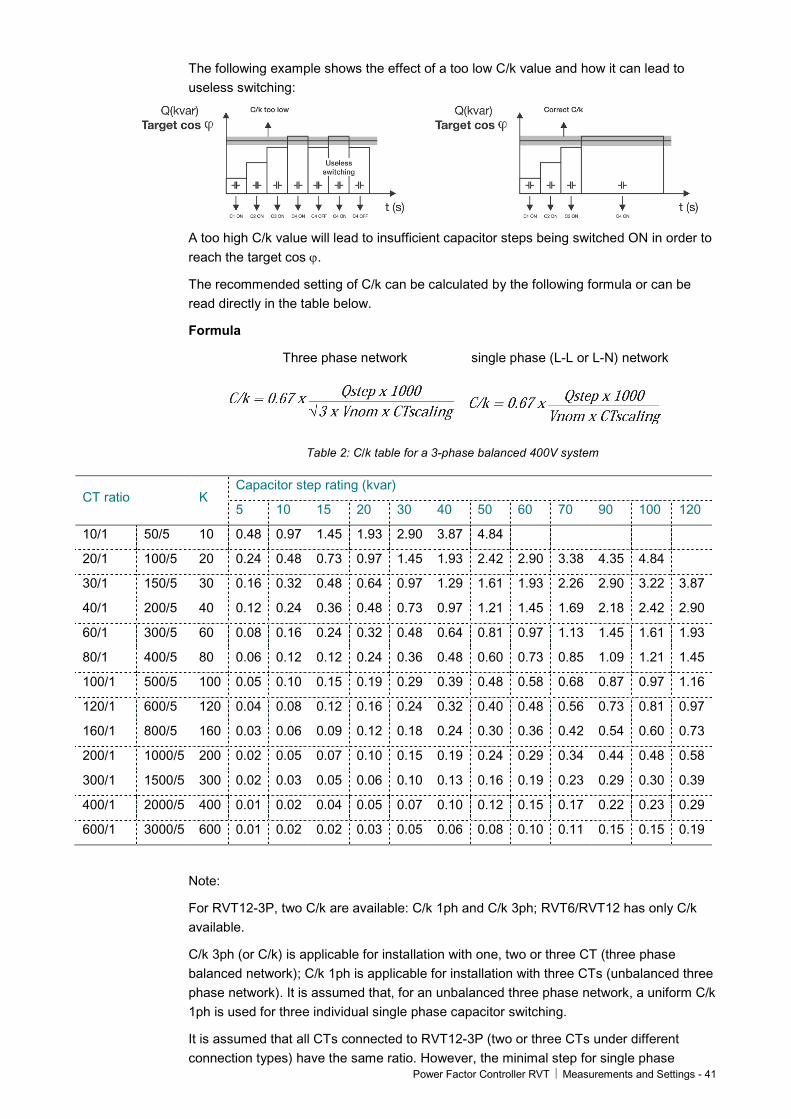
4.2.1.2 Installation settings Start screen-> Settings-> Manual settings-> installation settings
RVT installation settings give instructions on how to set CT related parameters.
Figure 36: RVT installation settings
CT scaling: current transformer ratio.
Example: a 250A / 5A CT has a CT Scaling of 50.
C/k: starting current of the RVT Controller. It is usually set equal to 2/3 of the current of the capacitor step (Qstep) (see paragraph 4.2.1.1.)
It represents the threshold current value for the RVT to switch ON or OFF a capacitor step. The C/k can be programmed from 0.01 to 5.
Power Factor Controller RVT Measurements and Settings - 41
The following example shows the effect of a too low C/k value and how it can lead to useless switching:
A too high C/k value will lead to insufficient capacitor steps being switched ON in order to reach the target cos ϕ.
The recommended setting of C/k can be calculated by the following formula or can be read directly in the table below.
Formula
Three phase network single phase (L-L or L-N) network
Table 2: C/k table for a 3-phase balanced 400V system
CT ratio K Capacitor step rating (kvar)
5 10 15 20 30 40 50 60 70 90 100 120
10/1 50/5 10 0.48 0.97 1.45 1.93 2.90 3.87 4.84
20/1 100/5 20 0.24 0.48 0.73 0.97 1.45 1.93 2.42 2.90 3.38 4.35 4.84
30/1 150/5 30 0.16 0.32 0.48 0.64 0.97 1.29 1.61 1.93 2.26 2.90 3.22 3.87
40/1 200/5 40 0.12 0.24 0.36 0.48 0.73 0.97 1.21 1.45 1.69 2.18 2.42 2.90
60/1 300/5 60 0.08 0.16 0.24 0.32 0.48 0.64 0.81 0.97 1.13 1.45 1.61 1.93
80/1 400/5 80 0.06 0.12 0.12 0.24 0.36 0.48 0.60 0.73 0.85 1.09 1.21 1.45
100/1 500/5 100 0.05 0.10 0.15 0.19 0.29 0.39 0.48 0.58 0.68 0.87 0.97 1.16
120/1 600/5 120 0.04 0.08 0.12 0.16 0.24 0.32 0.40 0.48 0.56 0.73 0.81 0.97
160/1 800/5 160 0.03 0.06 0.09 0.12 0.18 0.24 0.30 0.36 0.42 0.54 0.60 0.73
200/1 1000/5 200 0.02 0.05 0.07 0.10 0.15 0.19 0.24 0.29 0.34 0.44 0.48 0.58
300/1 1500/5 300 0.02 0.03 0.05 0.06 0.10 0.13 0.16 0.19 0.23 0.29 0.30 0.39
400/1 2000/5 400 0.01 0.02 0.04 0.05 0.07 0.10 0.12 0.15 0.17 0.22 0.23 0.29
600/1 3000/5 600 0.01 0.02 0.02 0.03 0.05 0.06 0.08 0.10 0.11 0.15 0.15 0.19
Note:
For RVT12-3P, two C/k are available: C/k 1ph and C/k 3ph; RVT6/RVT12 has only C/k available.
C/k 3ph (or C/k) is applicable for installation with one, two or three CT (three phase balanced network); C/k 1ph is applicable for installation with three CTs (unbalanced three phase network). It is assumed that, for an unbalanced three phase network, a uniform C/k 1ph is used for three individual single phase capacitor switching.
It is assumed that all CTs connected to RVT12-3P (two or three CTs under different connection types) have the same ratio. However, the minimal step for single phase
42 – Measurements and Settings Power Factor Controller RVT
capacitor and three phase capacitor could be different; this entails two different C/k values for RVT.
Phase shift (applicable to base model only): phase shift between voltage and current introduced by the measurement connection.
If the RVT is connected as shown on the connection diagram described in paragraph 2.3, the phase shift value is 90° (default setting).
For other connection, the phase shift to be programmed can be selected from the tables in the appendix A6.
Please note that the RVT can adapt automatically the phase shift during automatic commissioning.
4.2.1.3 User settings Start screen-> Settings-> Manual settings-> user settings
User Settings allows the users to set different target power factors and alarm delays.
Figure 37: RVT user settings
Target cos ϕ: target displacement power factor.
The target cos ϕ value can be set between 0.70 inductive and 0.70 capacitive.
indicates an inductive cos ϕ and indicates a capacitive cos ϕ.
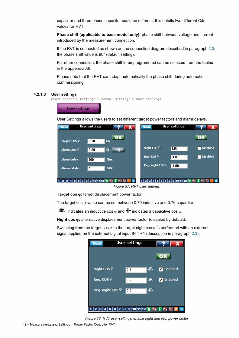
Night cos ϕ: alternative displacement power factor (disabled by default).
Switching from the target cos ϕ to the target night cos ϕ is performed with an external signal applied on the external digital input IN 1 +/- (description in paragraph 2.3).
Figure 38: RVT user settings: enable night and reg. power factor
Power Factor Controller RVT Measurements and Settings - 43
Reg. cos ϕ: alternative target displacement power factor. Activated when power flow is reversed: P < 0 (disabled by default).
Alarm: alarm relay parameters can be set for the Alarm cos ϕ condition:
The Alarm cos ϕ condition is fulfilled when: all the capacitor steps are ON and the actual cos ϕ value is below the alarm cos ϕ threshold value such that at least one step is needed.
• Alarm delay: duration of alarm cos ϕ condition before the relay closes.
• Alarm reset delay: delay time before the relay opens after the alarm condition has disappeared.
• Alarm cos ϕ: threshold value
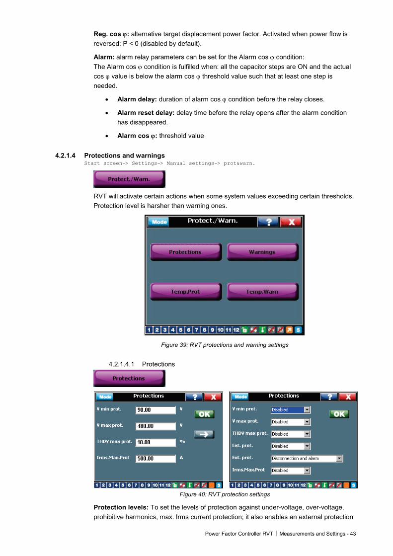
4.2.1.4 Protections and warnings Start screen-> Settings-> Manual settings-> prot&warn.
RVT will activate certain actions when some system values exceeding certain thresholds. Protection level is harsher than warning ones.
Figure 39: RVT protections and warning settings
4.2.1.4.1 Protections
Figure 40: RVT protection settings
Protection levels: To set the levels of protection against under-voltage, over-voltage, prohibitive harmonics, max. Irms current protection; it also enables an external protection
44 – Measurements and Settings Power Factor Controller RVT
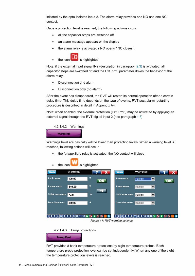
initiated by the opto-isolated input 2. The alarm relay provides one NO and one NC contact.
Once a protection level is reached, the following actions occur:
• all the capacitor steps are switched off
• an alarm message appears on the display
• the alarm relay is activated ( NO opens / NC closes )
• the icon is highlighted
Note: if the external input signal IN2 (description in paragraph 2.3) is activated, all capacitor steps are switched off and the Ext. prot. parameter drives the behavior of the alarm relay:
• Disconnection and alarm
• Disconnection only (no alarm)
After the event has disappeared, the RVT will restart its normal operation after a certain delay time. This delay time depends on the type of events. RVT post alarm restarting procedure is described in detail in Appendix A4.
Note: when enabled, the external protection (Ext. Prot.) may be activated by applying an external signal through the RVT digital input 2 (see paragraph 1.3).
4.2.1.4.2 Warnings
Warnings level are basically will be lower than protection levels. When a warning level is reached, following actions will occur:
• the fan/auxiliary relay is activated: the NO contact will close
• the icon is highlighted
Figure 41: RVT warning settings
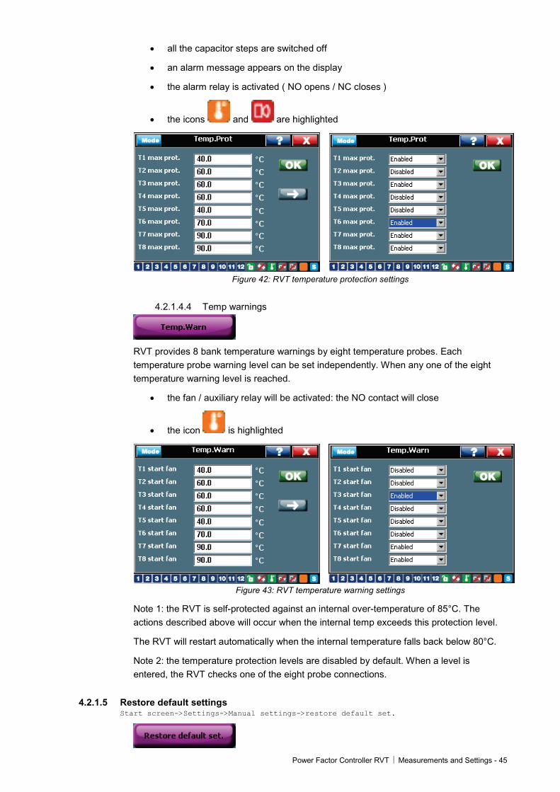
4.2.1.4.3 Temp protections
RVT provides 8 bank temperature protections by eight temperature probes. Each temperature probe protection level can be set independently. When any one of the eight the temperature protection levels is reached.
Power Factor Controller RVT Measurements and Settings - 45
• all the capacitor steps are switched off
• an alarm message appears on the display
• the alarm relay is activated ( NO opens / NC closes )
• the icons and are highlighted
Figure 42: RVT temperature protection settings
4.2.1.4.4 Temp warnings
RVT provides 8 bank temperature warnings by eight temperature probes. Each temperature probe warning level can be set independently. When any one of the eight temperature warning level is reached.
• the fan / auxiliary relay will be activated: the NO contact will close
• the icon is highlighted
Figure 43: RVT temperature warning settings
Note 1: the RVT is self-protected against an internal over-temperature of 85°C. The actions described above will occur when the internal temp exceeds this protection level.
The RVT will restart automatically when the internal temperature falls back below 80°C.
Note 2: the temperature protection levels are disabled by default. When a level is entered, the RVT checks one of the eight probe connections.
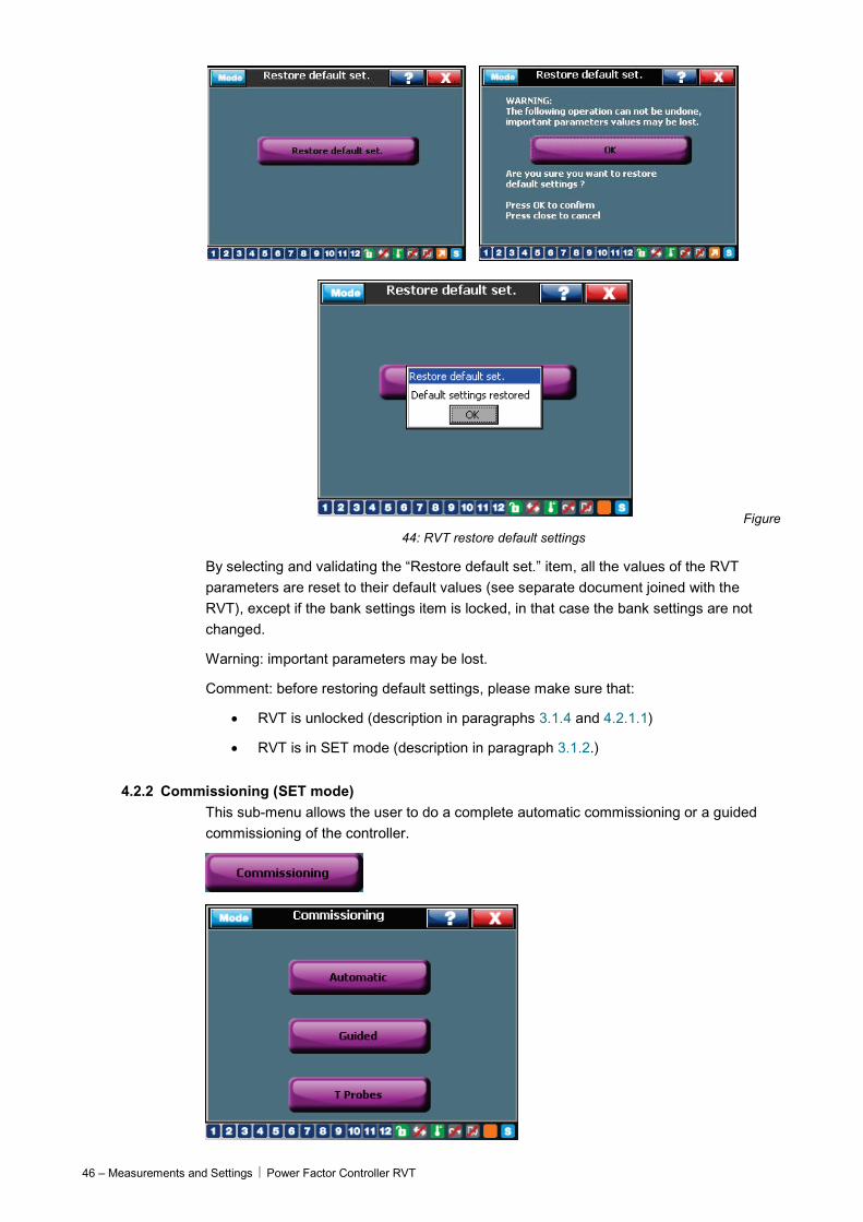
4.2.1.5 Restore default settings Start screen->Settings->Manual settings->restore default set.
46 – Measurements and Settings Power Factor Controller RVT
Figure 44: RVT restore default settings
By selecting and validating the “Restore default set.” item, all the values of the RVT parameters are reset to their default values (see separate document joined with the RVT), except if the bank settings item is locked, in that case the bank settings are not changed.
Warning: important parameters may be lost.
Comment: before restoring default settings, please make sure that:
• RVT is unlocked (description in paragraphs 3.1.4 and 4.2.1.1)
• RVT is in SET mode (description in paragraph 3.1.2.)
4.2.2 Commissioning (SET mode) This sub-menu allows the user to do a complete automatic commissioning or a guided commissioning of the controller.

Power Factor Controller RVT Measurements and Settings - 47
4.2.2.1 Automatic Commissioning
Please refer to section 3.3 for more details.
4.2.2.2 Guided Commissioning
The RVT performs a guided commissioning process. The following parameters (see table below) must be entered.
Note:
Before performing guided commissioning, please make sure that:
1. RVT is unlocked (description in paragraphs 3.1.4 and 4.2.1.1)
2. RVT is in SET mode (description in paragraph 3.1.2.)
3. if you have a short-circuit on the CT’s secondary winding do not forget to open it after having connected the current input of the PF Controller.
Guided commissioning (parameters to set)
Parameter Description
1Ph / 3Ph Bank connection type and RVT measurement connection
Phase rotation Check phase rotation
C.T. scaling Current Transformer ratio.
CT redirection Redirect CT inputs in case of CT’s placed on wrong phase
Phase shift Phase shift between voltage and current introduced by the measurement connections. The phase shift is 90° (default setting) when the RVT is connected as shown on wiring diagram (see paragraph 2.3). For other connections, please see appendix A.5.
V scaling External voltage transformer ratio.
V nom Nominal bank voltage.
ON-Delay
OFF-Delay
Switching ON delay time.
Switching OFF delay time.
Sequence Relative reactive power value of each output.
Q step Smallest reactive power difference between steps.
C/k Set the starting current
Target cos ϕ Target displacement power factor.
4.2.2.3 T Probes commissioning
RVT can connect up to eight temperature probes in a daisy chain. Each probe needs to be commissioned as following procedures before it can be used.
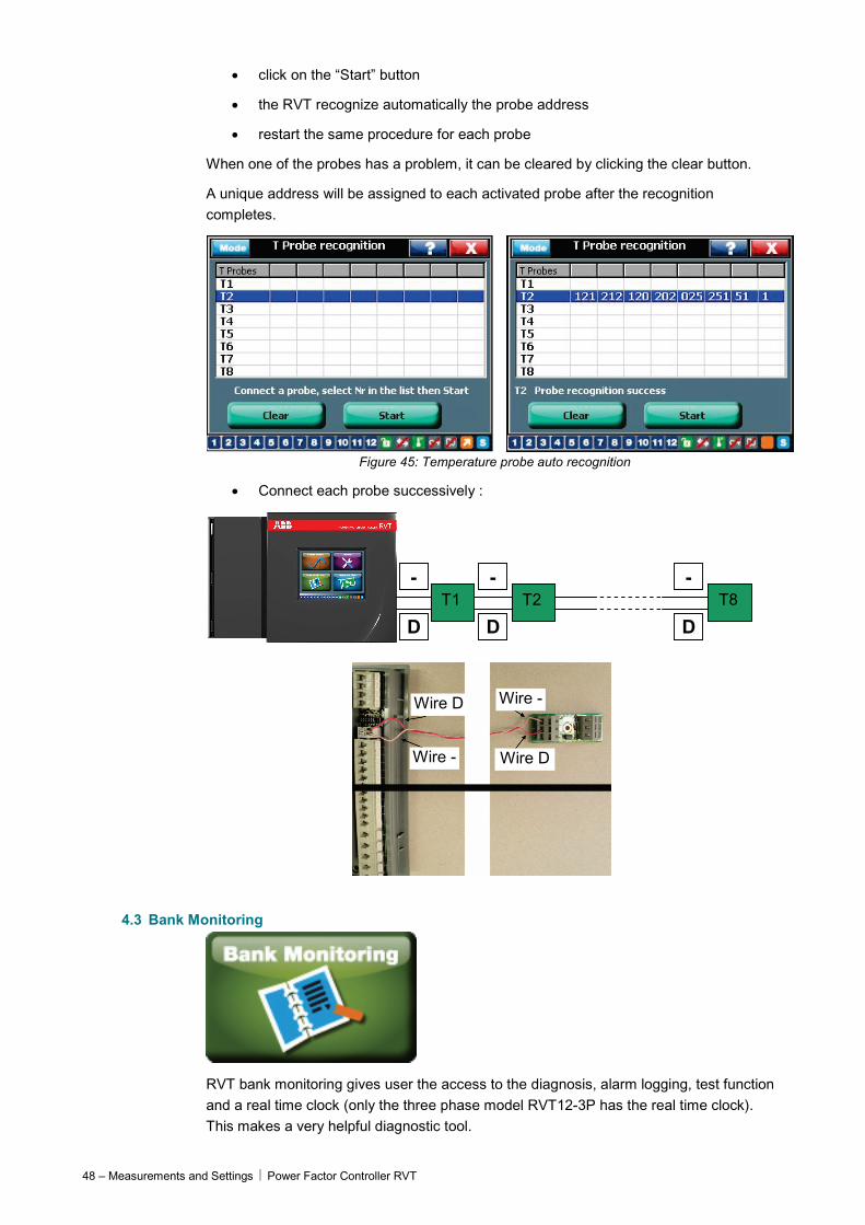
Each probe has to be recognized one by one:
• connect the probe to the temperature probe input (one probe only)
• click on a row to assign a probe number
48 – Measurements and Settings Power Factor Controller RVT
• click on the “Start” button
• the RVT recognize automatically the probe address
• restart the same procedure for each probe
When one of the probes has a problem, it can be cleared by clicking the clear button.
A unique address will be assigned to each activated probe after the recognition completes.
Figure 45: Temperature probe auto recognition
• Connect each probe successively :
T1 T2 T8
Wire D
Wire D Wire -
Wire -
D
-
D
-
D
-
4.3 Bank Monitoring
RVT bank monitoring gives user the access to the diagnosis, alarm logging, test function and a real time clock (only the three phase model RVT12-3P has the real time clock). This makes a very helpful diagnostic tool.
Power Factor Controller RVT Measurements and Settings - 49
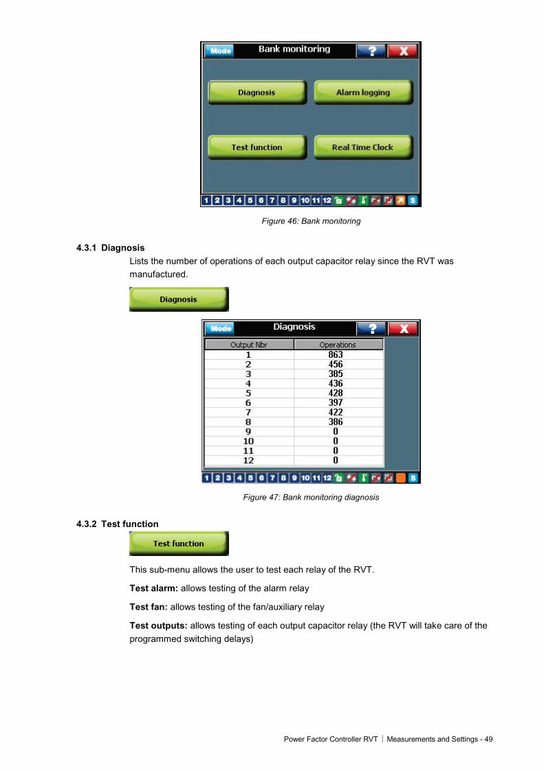
Figure 46: Bank monitoring
4.3.1 Diagnosis Lists the number of operations of each output capacitor relay since the RVT was manufactured.
Figure 47: Bank monitoring diagnosis
4.3.2 Test function
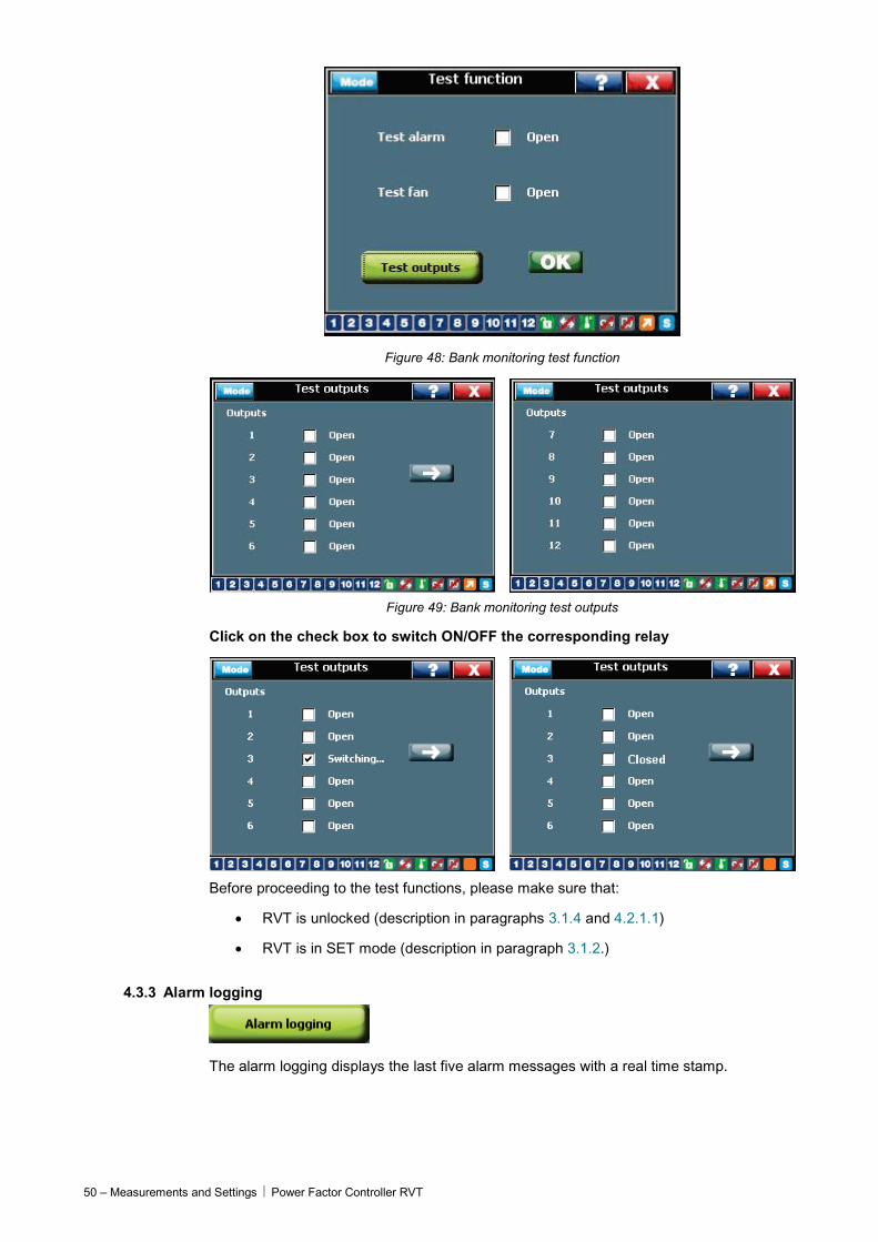
This sub-menu allows the user to test each relay of the RVT.
Test alarm: allows testing of the alarm relay
Test fan: allows testing of the fan/auxiliary relay
Test outputs: allows testing of each output capacitor relay (the RVT will take care of the programmed switching delays)
50 – Measurements and Settings Power Factor Controller RVT
Figure 48: Bank monitoring test function
Figure 49: Bank monitoring test outputs
Click on the check box to switch ON/OFF the corresponding relay
Before proceeding to the test functions, please make sure that:
• RVT is unlocked (description in paragraphs 3.1.4 and 4.2.1.1)
• RVT is in SET mode (description in paragraph 3.1.2.)
4.3.3 Alarm logging
The alarm logging displays the last five alarm messages with a real time stamp.
Power Factor Controller RVT Measurements and Settings - 51
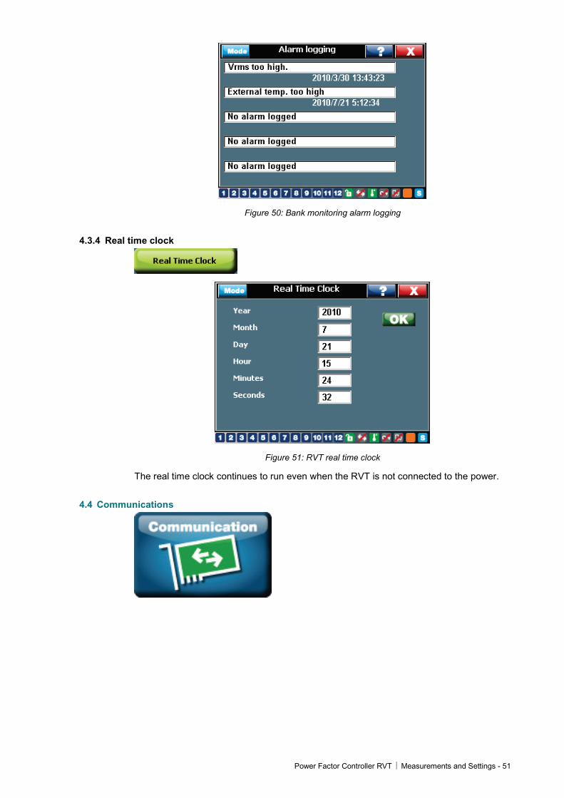
Figure 50: Bank monitoring alarm logging
4.3.4 Real time clock
Figure 51: RVT real time clock
The real time clock continues to run even when the RVT is not connected to the power.
4.4 Communications
52 – Measurements and Settings Power Factor Controller RVT
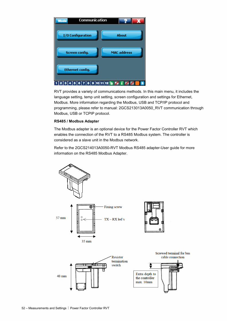
RVT provides a variety of communications methods. In this main menu, it includes the language setting, temp unit setting, screen configuration and settings for Ethernet, Modbus. More information regarding the Modbus, USB and TCP/IP protocol and programming, please refer to manual: 2GCS213013A0050_RVT communication through Modbus, USB or TCPIP protocol.
RS485 / Modbus Adapter
The Modbus adapter is an optional device for the Power Factor Controller RVT which enables the connection of the RVT to a RS485 Modbus system. The controller is considered as a slave unit in the Modbus network.
Refer to the 2GCS214013A0050-RVT Modbus RS485 adapter-User guide for more information on the RS485 Modbus Adapter.
Power Factor Controller RVT Measurements and Settings - 53
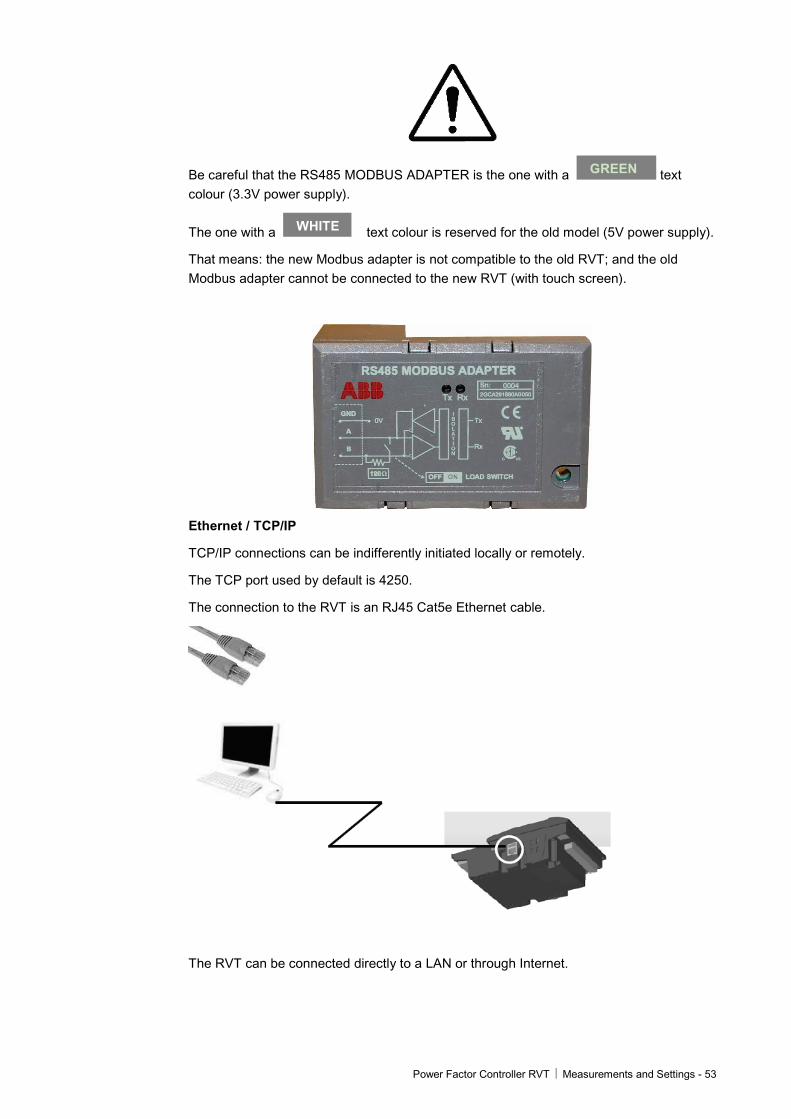
Be careful that the RS485 MODBUS ADAPTER is the one with a text colour (3.3V power supply).
The one with a text colour is reserved for the old model (5V power supply).
That means: the new Modbus adapter is not compatible to the old RVT; and the old Modbus adapter cannot be connected to the new RVT (with touch screen).
Ethernet / TCP/IP
TCP/IP connections can be indifferently initiated locally or remotely.
The TCP port used by default is 4250.
The connection to the RVT is an RJ45 Cat5e Ethernet cable.
The RVT can be connected directly to a LAN or through Internet.
WHITE
GREEN
54 – Measurements and Settings Power Factor Controller RVT
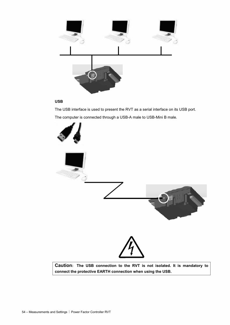
USB
The USB interface is used to present the RVT as a serial interface on its USB port.
The computer is connected through a USB-A male to USB-Mini B male.
Caution: The USB connection to the RVT is not isolated. It is mandatory to
connect the protective EARTH connection when using the USB.

Power Factor Controller RVT Measurements and Settings - 55
4.4.1 I/O configuration
Figure 52: RVT I/O configuration
4.4.1.1 Set languages
Five different languages may be selected to dialog with the RVT.
The user should come back to the main menu so that the selected language is activated.

56 – Measurements and Settings Power Factor Controller RVT
Figure 53: RVT language selection
4.4.1.2 Temp unit
This menu provides two temperature units: Celsius and Fahrenheit.
The selected unit will be applicable in all other temperature measurements or settings.
4.4.1.3 Communications settings
Modbus and Ethernet connections have to be configured to run properly.
Figure 54: RVT communications protocol setting

Power Factor Controller RVT Measurements and Settings - 57
Figure 55: RVT Modbus protocol setting
The slave address is the one used by the Modbus master to address the RVT through Modbus.
Baud rate, Parity, Stop bit shall match exactly the communication settings of the Modbus master which controls the RS485 / Modbus network.
The RVT needs an IP address to be connected directly to a PC or to an Ethernet network.
This IP address may be fixed and entered manually if DHCP is disabled. The default address is 192.168.1.40.
In case the IP address is given automatically by a gateway or Ethernet LAN , set DHCP to enabled.
Some examples are given below :
Example 1 : The below screen shows the default settings to connect directly to a PC ( note that the PC need to be configured accordingly with a fixed IP address of 192.168.1.1, Subnet mask of 255.255.255.0 , DHCP disabled )
Figure 56: RVT TCP/IP protocol setting
58 – Measurements and Settings Power Factor Controller RVT
Example 2 : The below screen shows the default settings to connect to an Ethernet network ( note that the PC which is also connected to the LAN has its own IP address given by the network with DHCP enabled )
Details about the communication settings can be found in the manual: 2GCS213013A0050_RVT communication through Modbus, USB or TCPIP protocol.
Reboot the RVT to initialize it with these parameters.
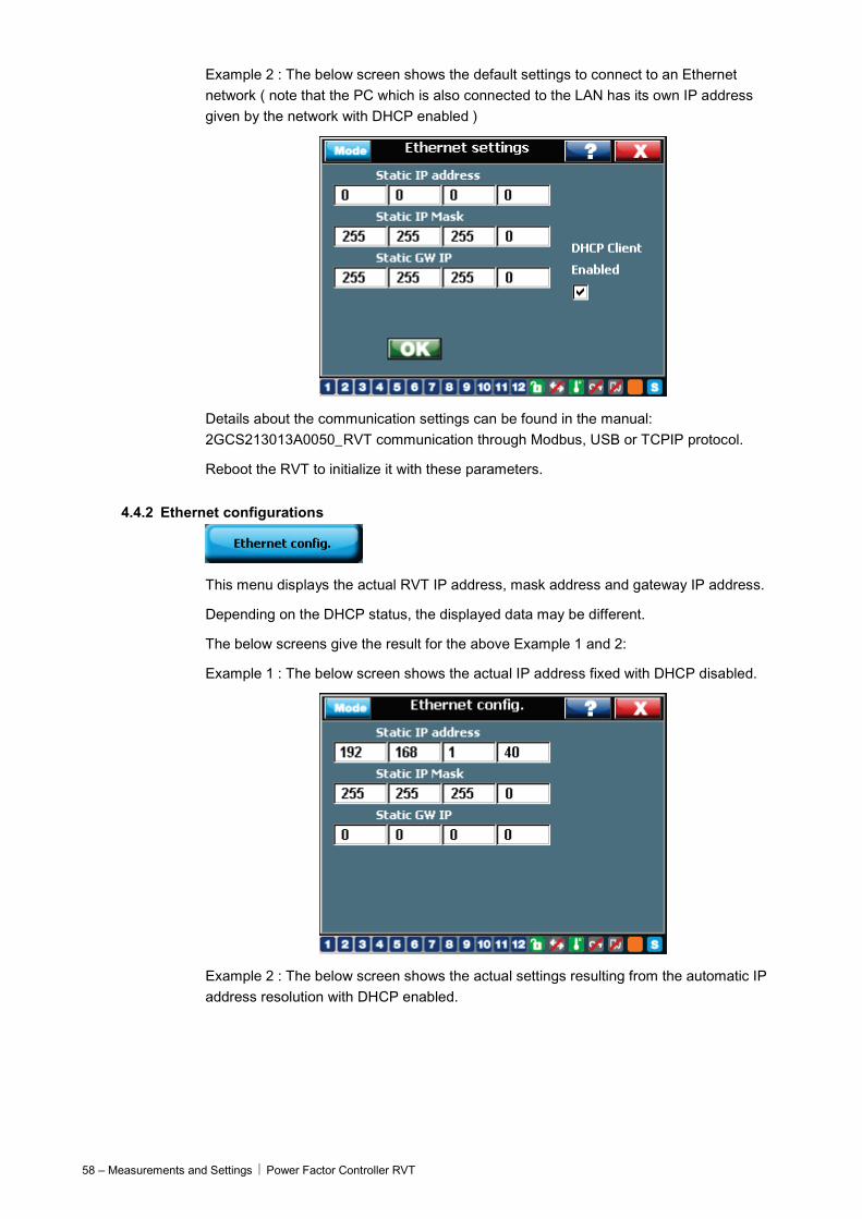
4.4.2 Ethernet configurations
This menu displays the actual RVT IP address, mask address and gateway IP address.
Depending on the DHCP status, the displayed data may be different.
The below screens give the result for the above Example 1 and 2:
Example 1 : The below screen shows the actual IP address fixed with DHCP disabled.
Example 2 : The below screen shows the actual settings resulting from the automatic IP address resolution with DHCP enabled.
Power Factor Controller RVT Measurements and Settings - 59
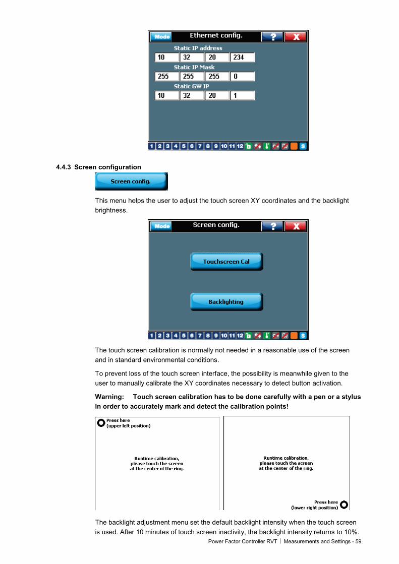
4.4.3 Screen configuration
This menu helps the user to adjust the touch screen XY coordinates and the backlight brightness.
The touch screen calibration is normally not needed in a reasonable use of the screen and in standard environmental conditions.
To prevent loss of the touch screen interface, the possibility is meanwhile given to the user to manually calibrate the XY coordinates necessary to detect button activation.
Warning: Touch screen calibration has to be done carefully with a pen or a stylus in order to accurately mark and detect the calibration points!
The backlight adjustment menu set the default backlight intensity when the touch screen is used. After 10 minutes of touch screen inactivity, the backlight intensity returns to 10%.
60 – Measurements and Settings Power Factor Controller RVT
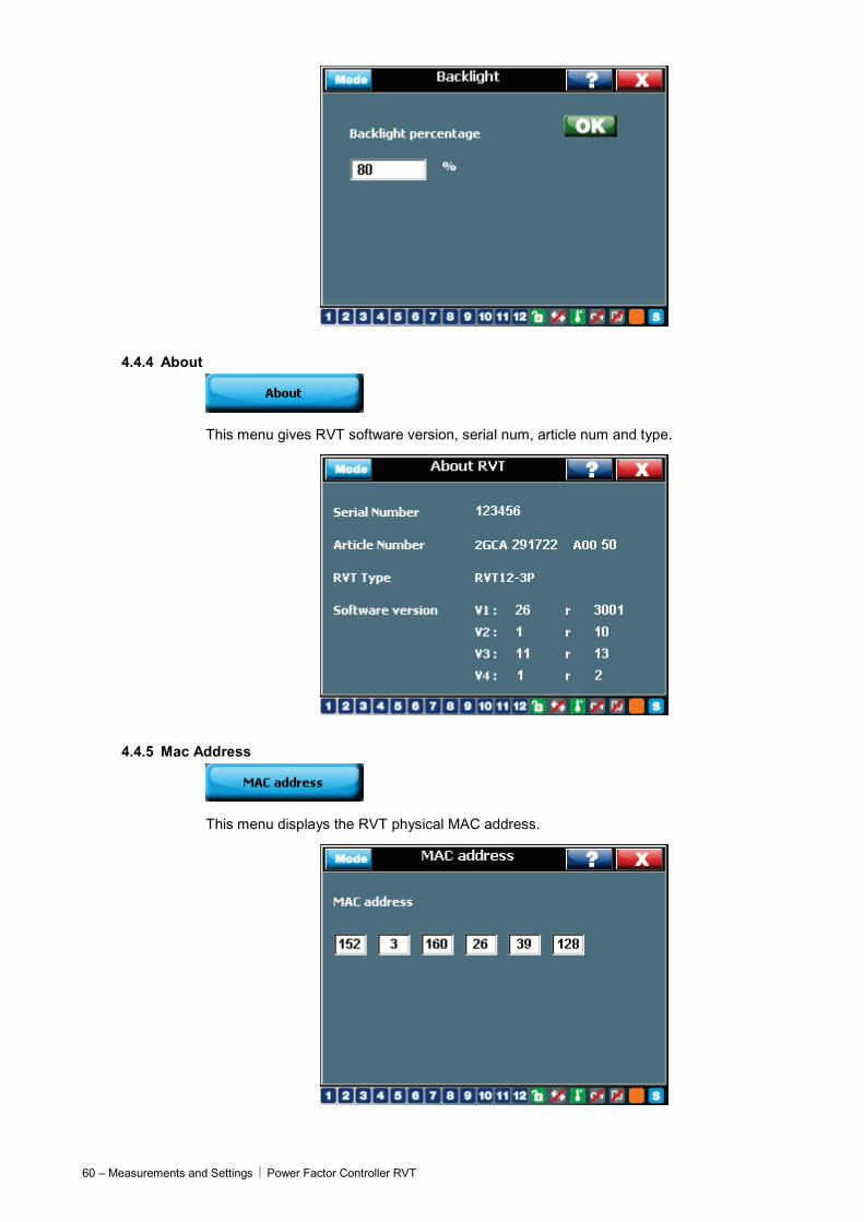
4.4.4 About
This menu gives RVT software version, serial num, article num and type.
4.4.5 Mac Address
This menu displays the RVT physical MAC address.
Power Factor Controller RVT Appendices - 61
Appendices
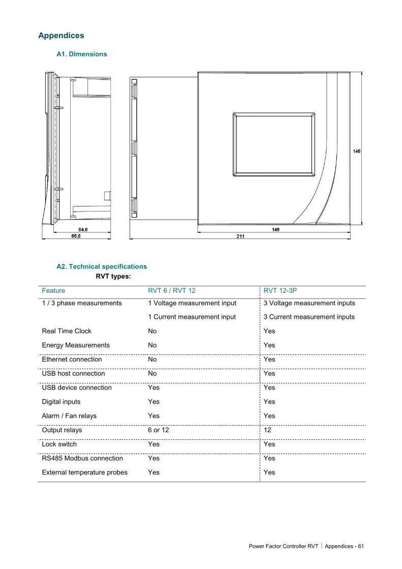
A1. Dimensions
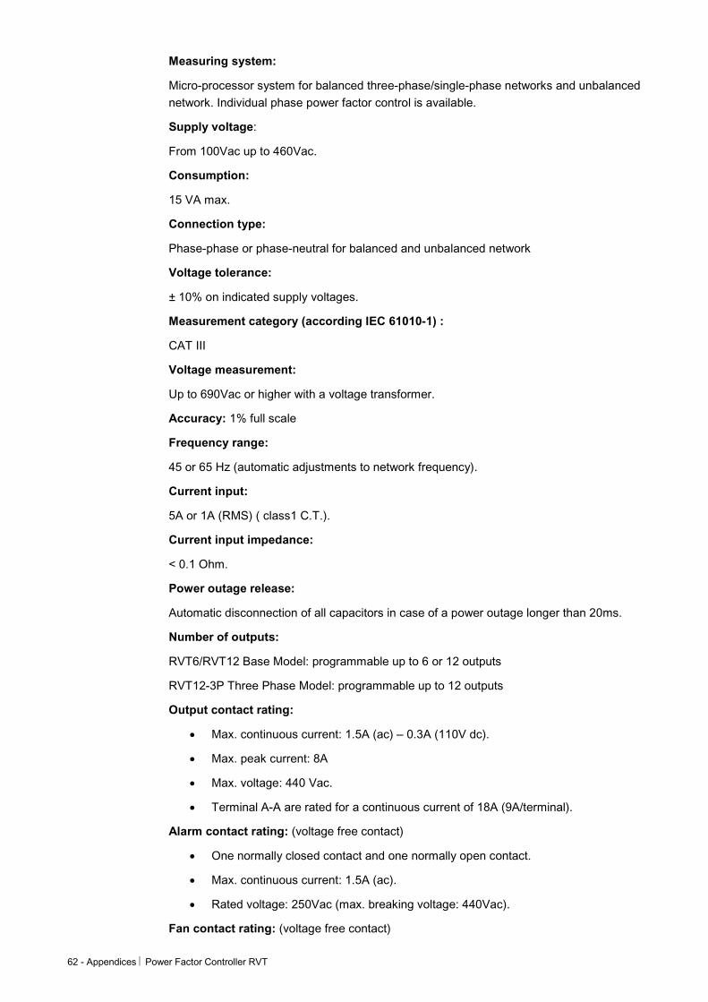
A2. Technical specifications RVT types:
Feature RVT 6 / RVT 12 RVT 12-3P
1 / 3 phase measurements 1 Voltage measurement input
1 Current measurement input
3 Voltage measurement inputs
3 Current measurement inputs
Real Time Clock No Yes
Energy Measurements No Yes
Ethernet connection No Yes
USB host connection No Yes
USB device connection Yes Yes
Digital inputs Yes Yes
Alarm / Fan relays Yes Yes
Output relays 6 or 12 12
Lock switch Yes Yes
RS485 Modbus connection Yes Yes
External temperature probes Yes Yes
62 - Appendices Power Factor Controller RVT
Measuring system:
Micro-processor system for balanced three-phase/single-phase networks and unbalanced network. Individual phase power factor control is available.
Supply voltage:
From 100Vac up to 460Vac.
Consumption:
15 VA max.
Connection type:
Phase-phase or phase-neutral for balanced and unbalanced network
Voltage tolerance:
± 10% on indicated supply voltages.
Measurement category (according IEC 61010-1) :
CAT III
Voltage measurement:
Up to 690Vac or higher with a voltage transformer.
Accuracy: 1% full scale
Frequency range:
45 or 65 Hz (automatic adjustments to network frequency).
Current input:
5A or 1A (RMS) ( class1 C.T.).
Current input impedance:
< 0.1 Ohm.
Power outage release:
Automatic disconnection of all capacitors in case of a power outage longer than 20ms.
Number of outputs:
RVT6/RVT12 Base Model: programmable up to 6 or 12 outputs
RVT12-3P Three Phase Model: programmable up to 12 outputs
Output contact rating:
• Max. continuous current: 1.5A (ac) – 0.3A (110V dc).
• Max. peak current: 8A
• Max. voltage: 440 Vac.
• Terminal A-A are rated for a continuous current of 18A (9A/terminal).
Alarm contact rating: (voltage free contact)
• One normally closed contact and one normally open contact.
• Max. continuous current: 1.5A (ac).
• Rated voltage: 250Vac (max. breaking voltage: 440Vac).
Fan contact rating: (voltage free contact)
Power Factor Controller RVT Appendices - 63
• Normally open contact.
• Max. continuous current: 1.5A (ac).
• Rated voltage: 250Vac (max. breaking voltage: 440Vac).
Power factor setting:
From 0.7 inductive to 0.7 capacitive.
Starting current setting (C/k):
• 0.01 to 5A.
• automatic measurement of C/k.
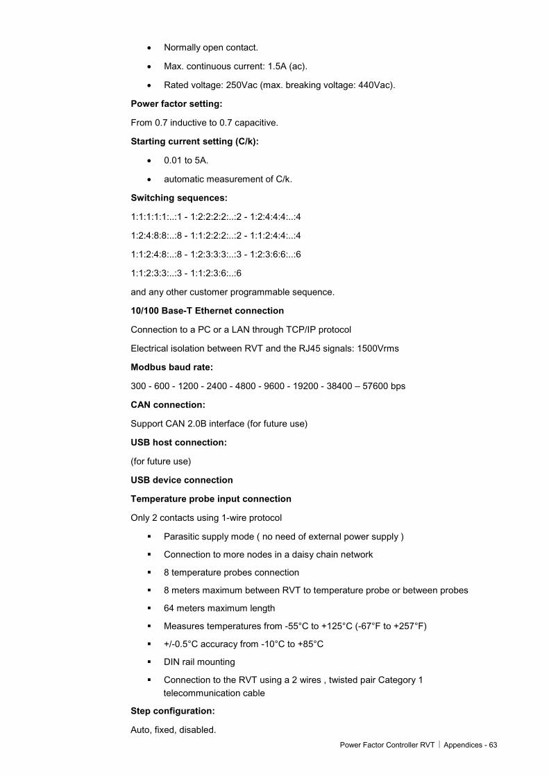
Switching sequences:
1:1:1:1:1:..:1 - 1:2:2:2:2:..:2 - 1:2:4:4:4:..:4
1:2:4:8:8:..:8 - 1:1:2:2:2:..:2 - 1:1:2:4:4:..:4
1:1:2:4:8:..:8 - 1:2:3:3:3:..:3 - 1:2:3:6:6:..:6
1:1:2:3:3:..:3 - 1:1:2:3:6:..:6
and any other customer programmable sequence.
10/100 Base-T Ethernet connection
Connection to a PC or a LAN through TCP/IP protocol
Electrical isolation between RVT and the RJ45 signals: 1500Vrms
Modbus baud rate:
300 - 600 - 1200 - 2400 - 4800 - 9600 - 19200 - 38400 – 57600 bps
CAN connection:
Support CAN 2.0B interface (for future use)
USB host connection:
(for future use)
USB device connection
Temperature probe input connection
Only 2 contacts using 1-wire protocol
Parasitic supply mode ( no need of external power supply )
Connection to more nodes in a daisy chain network
8 temperature probes connection
8 meters maximum between RVT to temperature probe or between probes
64 meters maximum length
Measures temperatures from -55°C to +125°C (-67°F to +257°F)
+/-0.5°C accuracy from -10°C to +85°C
DIN rail mounting
Connection to the RVT using a 2 wires , twisted pair Category 1 telecommunication cable
Step configuration:
Auto, fixed, disabled.
64 - Appendices Power Factor Controller RVT
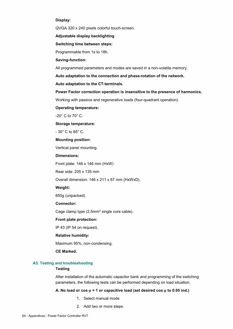
Display:
QVGA 320 x 240 pixels colorful touch-screen.
Adjustable display backlighting
Switching time between steps:
Programmable from 1s to 18h.
Saving-function:
All programmed parameters and modes are saved in a non-volatile memory.
Auto adaptation to the connection and phase-rotation of the network.
Auto adaptation to the CT-terminals.
Power Factor correction operation is insensitive to the presence of harmonics.
Working with passive and regenerative loads (four-quadrant operation).
Operating temperature:
-20° C to 70° C.
Storage temperature:
- 30° C to 85° C.
Mounting position:
Vertical panel mounting.
Dimensions:
Front plate: 146 x 146 mm (HxW)
Rear side: 205 x 135 mm
Overall dimension: 146 x 211 x 67 mm (HxWxD).
Weight:
650g (unpacked).
Connector:
Cage clamp type (2.5mm² single core cable).
Front plate protection:
IP 43 (IP 54 on request).
Relative humidity:
Maximum 95%; non-condensing.
CE Marked.
A3. Testing and troubleshooting Testing
After installation of the automatic capacitor bank and programming of the switching parameters, the following tests can be performed depending on load situation.
A. No load or cos ϕ = 1 or capacitive load (set desired cos ϕ to 0.95 ind.)
1. Select manual mode
2. Add two or more steps.
Power Factor Controller RVT Appendices - 65
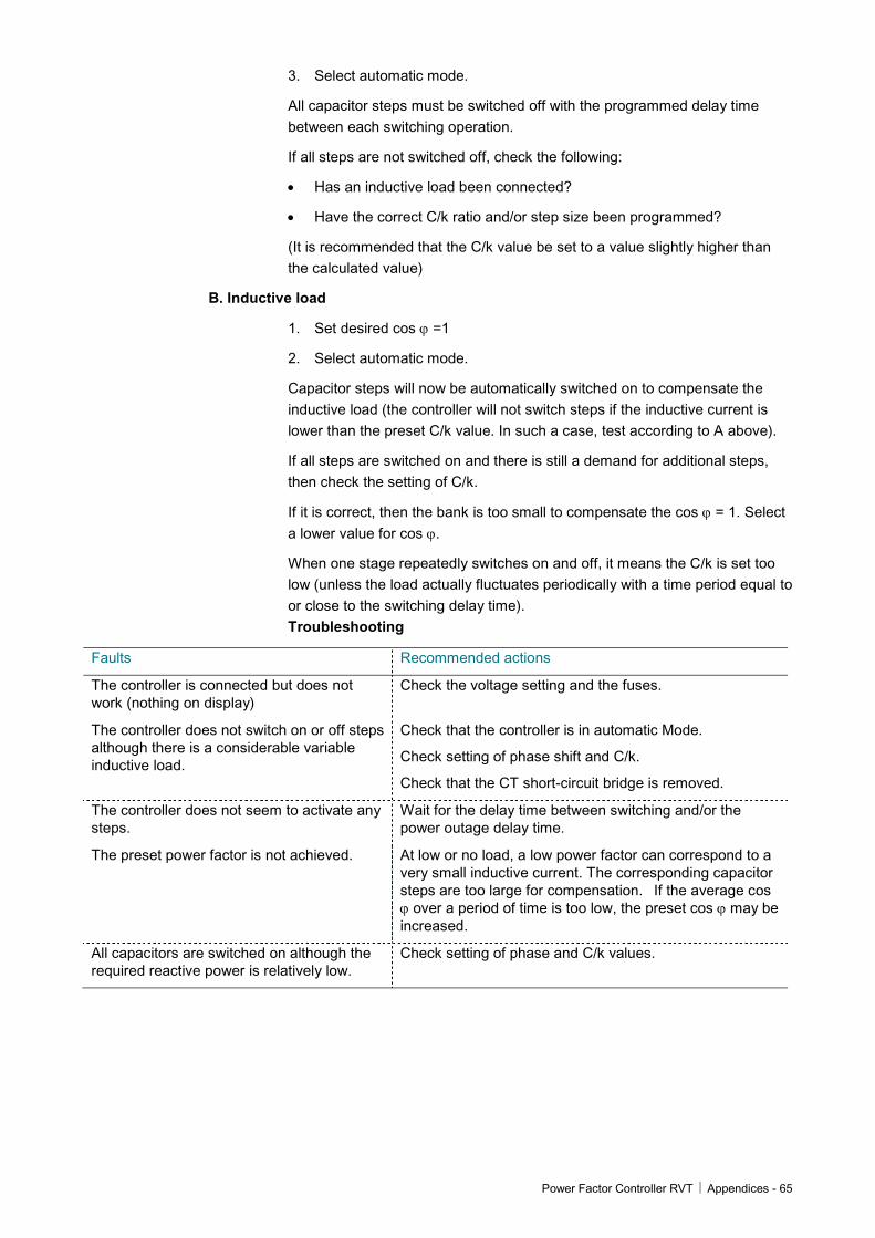
3. Select automatic mode.
All capacitor steps must be switched off with the programmed delay time between each switching operation.
If all steps are not switched off, check the following:
• Has an inductive load been connected?
• Have the correct C/k ratio and/or step size been programmed?
(It is recommended that the C/k value be set to a value slightly higher than the calculated value)
B. Inductive load
1. Set desired cos ϕ =1
2. Select automatic mode.
Capacitor steps will now be automatically switched on to compensate the inductive load (the controller will not switch steps if the inductive current is lower than the preset C/k value. In such a case, test according to A above).
If all steps are switched on and there is still a demand for additional steps, then check the setting of C/k.
If it is correct, then the bank is too small to compensate the cos ϕ = 1. Select a lower value for cos ϕ.
When one stage repeatedly switches on and off, it means the C/k is set too low (unless the load actually fluctuates periodically with a time period equal to or close to the switching delay time). Troubleshooting
Faults Recommended actions
The controller is connected but does not work (nothing on display)
Check the voltage setting and the fuses.
The controller does not switch on or off steps although there is a considerable variable inductive load.
Check that the controller is in automatic Mode.
Check setting of phase shift and C/k.
Check that the CT short-circuit bridge is removed.
The controller does not seem to activate any steps.
Wait for the delay time between switching and/or the power outage delay time.
The preset power factor is not achieved. At low or no load, a low power factor can correspond to a very small inductive current. The corresponding capacitor steps are too large for compensation. If the average cos ϕ over a period of time is too low, the preset cos ϕ may be increased.
All capacitors are switched on although the required reactive power is relatively low.
Check setting of phase and C/k values.
66 - Appendices Power Factor Controller RVT
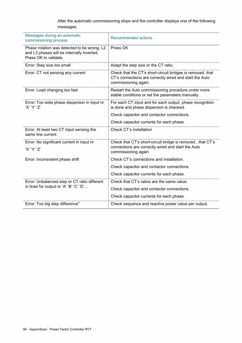
After the automatic commissioning stops and the controller displays one of the following messages:
Messages during an automatic commissioning process
Recommended actions
Phase rotation was detected to be wrong. L2 and L3 phases will be internally inverted. Press OK to validate.
Press OK
Error: Step size too small Adapt the step size or the CT ratio.
Error: CT not sensing any current Check that the CT’s short-circuit bridges is removed, that CT’s connections are correctly wired and start the Auto commissioning again.
Error: Load changing too fast Restart the Auto commissioning procedure under more stable conditions or set the parameters manually.
Error: Too wide phase dispersion in input nr ‘X’ ‘Y’ ‘Z’
For each CT input and for each output, phase recognition is done and phase dispersion is checked.
Check capacitor and contactor connections.
Check capacitor currents for each phase.
Error: At least two CT input sensing the same line current
Check CT’s installation
Error: No significant current in input nr
‘X’ ‘Y’ ‘Z’
Check that CT’s short-circuit bridge is removed , that CT’s connections are correctly wired and start the Auto commissioning again
Error: Inconsistent phase shift Check CT’s connections and installation.
Check capacitor and contactor connections.
Check capacitor currents for each phase.
Error: Unbalanced step or CT ratio different in lines for output nr ‘A’ ‘B’ ‘C’ ‘D’…
Check that CT’s ratios are the same value.
Check capacitor and contactor connections.
Check capacitor currents for each phase.
Error: Too big step difference" Check sequence and reactive power value per output.
Power Factor Controller RVT Appendices - 67
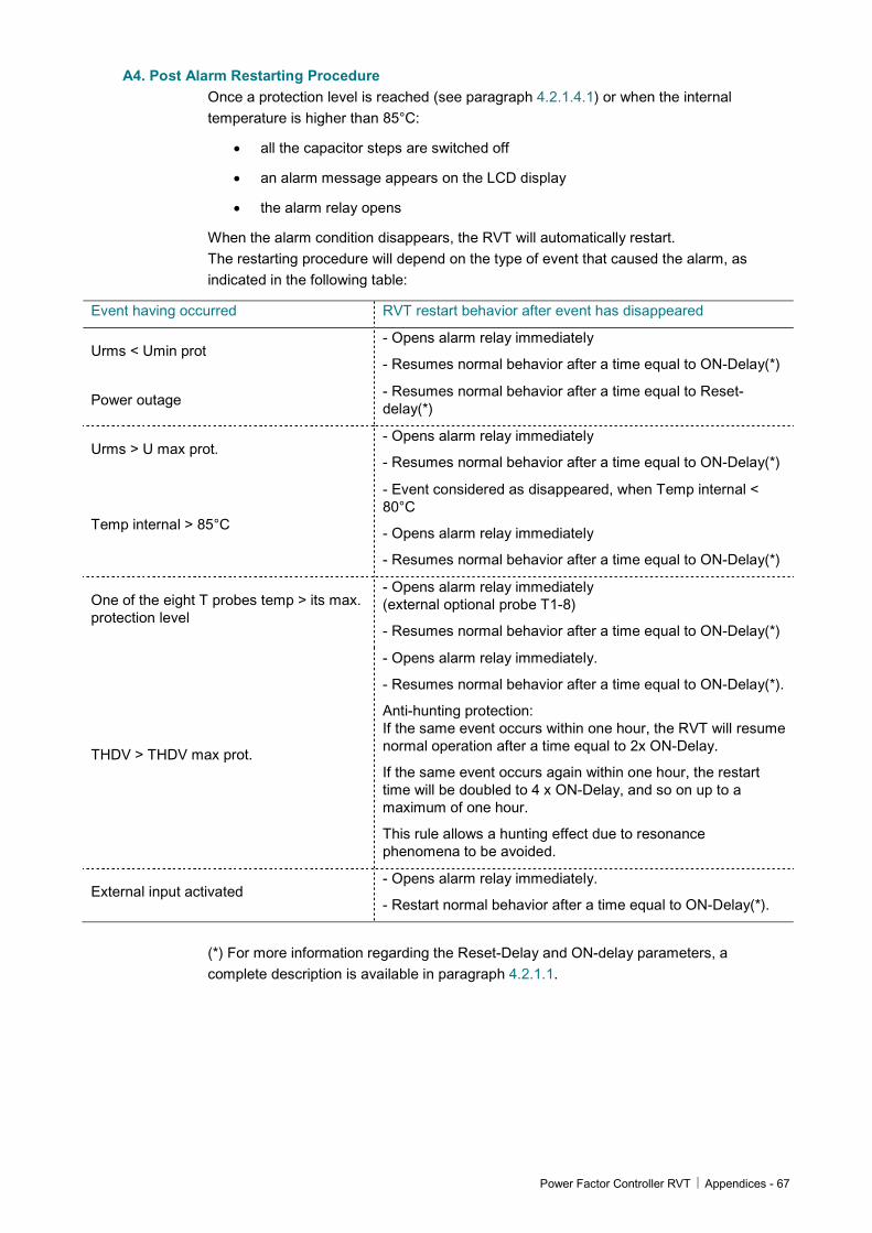
A4. Post Alarm Restarting Procedure Once a protection level is reached (see paragraph 4.2.1.4.1) or when the internal temperature is higher than 85°C:
• all the capacitor steps are switched off
• an alarm message appears on the LCD display
• the alarm relay opens
When the alarm condition disappears, the RVT will automatically restart. The restarting procedure will depend on the type of event that caused the alarm, as indicated in the following table:
Event having occurred RVT restart behavior after event has disappeared
Urms < Umin prot - Opens alarm relay immediately
- Resumes normal behavior after a time equal to ON-Delay(*)
Power outage - Resumes normal behavior after a time equal to Reset-delay(*)
Urms > U max prot. - Opens alarm relay immediately
- Resumes normal behavior after a time equal to ON-Delay(*)
Temp internal > 85°C
- Event considered as disappeared, when Temp internal < 80°C
- Opens alarm relay immediately
- Resumes normal behavior after a time equal to ON-Delay(*)
One of the eight T probes temp > its max. protection level
- Opens alarm relay immediately (external optional probe T1-8)
- Resumes normal behavior after a time equal to ON-Delay(*)
THDV > THDV max prot.
- Opens alarm relay immediately.
- Resumes normal behavior after a time equal to ON-Delay(*).
Anti-hunting protection: If the same event occurs within one hour, the RVT will resume normal operation after a time equal to 2x ON-Delay.
If the same event occurs again within one hour, the restart time will be doubled to 4 x ON-Delay, and so on up to a maximum of one hour.
This rule allows a hunting effect due to resonance phenomena to be avoided.
External input activated - Opens alarm relay immediately.
- Restart normal behavior after a time equal to ON-Delay(*).
(*) For more information regarding the Reset-Delay and ON-delay parameters, a complete description is available in paragraph 4.2.1.1.
68 - Appendices Power Factor Controller RVT
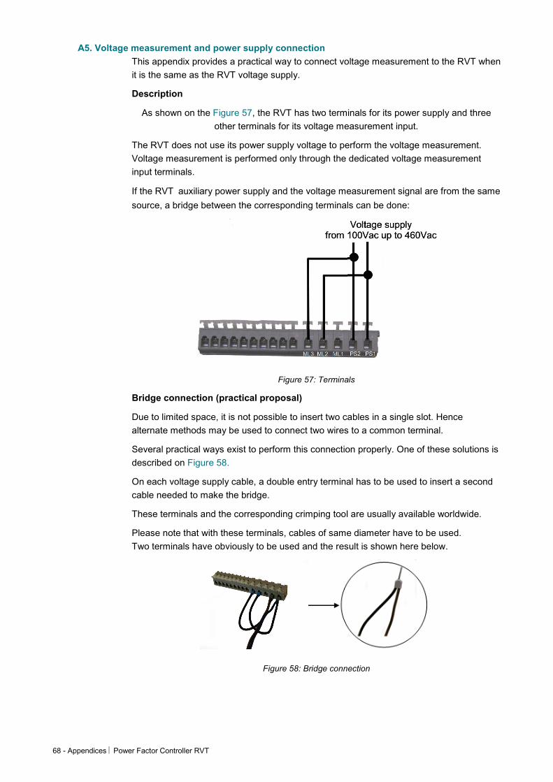
A5. Voltage measurement and power supply connection This appendix provides a practical way to connect voltage measurement to the RVT when it is the same as the RVT voltage supply.
Description
As shown on the Figure 57, the RVT has two terminals for its power supply and three other terminals for its voltage measurement input.
The RVT does not use its power supply voltage to perform the voltage measurement. Voltage measurement is performed only through the dedicated voltage measurement input terminals.
If the RVT auxiliary power supply and the voltage measurement signal are from the same
source, a bridge between the corresponding terminals can be done:
Figure 57: Terminals
Bridge connection (practical proposal)
Due to limited space, it is not possible to insert two cables in a single slot. Hence alternate methods may be used to connect two wires to a common terminal.
Several practical ways exist to perform this connection properly. One of these solutions is described on Figure 58.
On each voltage supply cable, a double entry terminal has to be used to insert a second cable needed to make the bridge.
These terminals and the corresponding crimping tool are usually available worldwide.
Please note that with these terminals, cables of same diameter have to be used. Two terminals have obviously to be used and the result is shown here below.
Figure 58: Bridge connection
Power Factor Controller RVT Appendices - 69
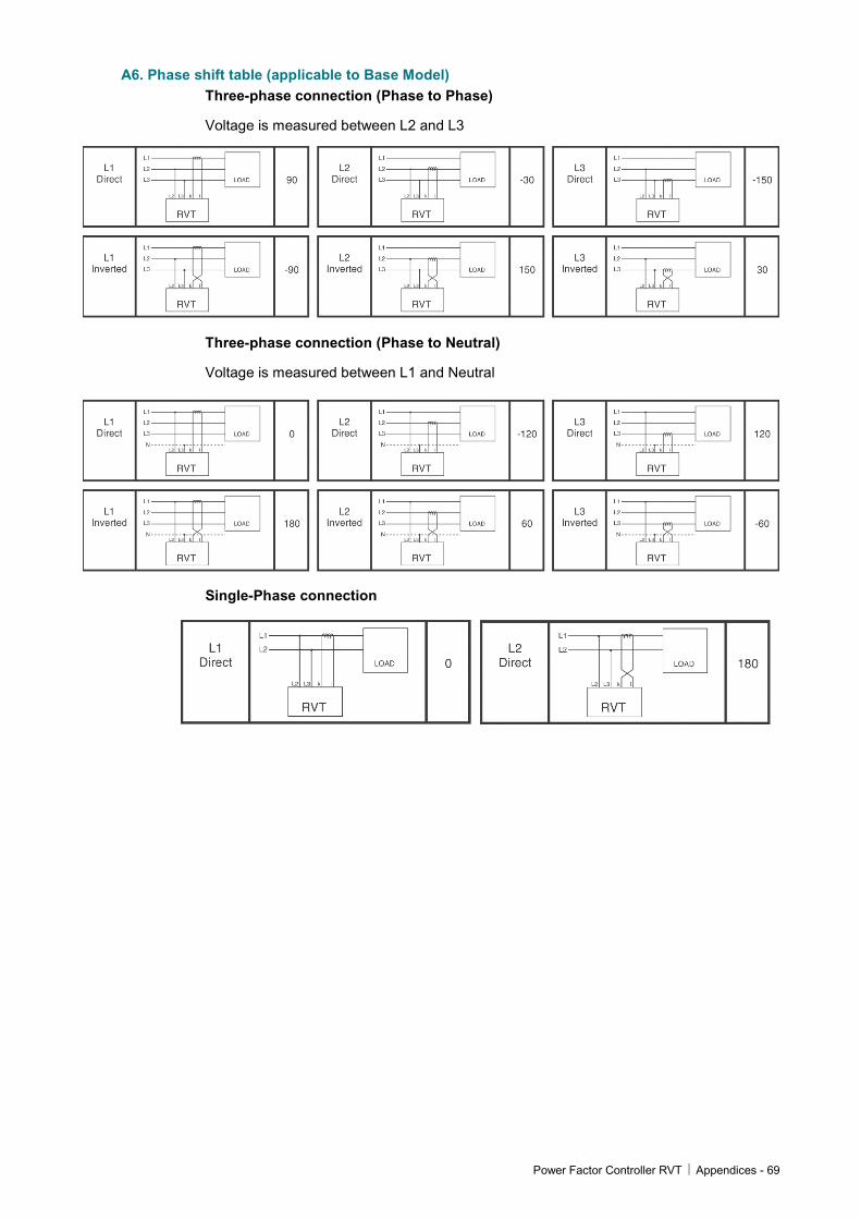
A6. Phase shift table (applicable to Base Model) Three-phase connection (Phase to Phase)
Voltage is measured between L2 and L3
Three-phase connection (Phase to Neutral)
Voltage is measured between L1 and Neutral
Single-Phase connection
70 - Appendices Power Factor Controller RVT
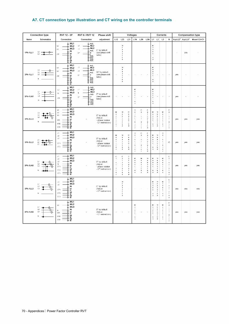
A7. CT connection type illustration and CT wiring on the controller terminals

Power Factor Controller RVT Appendices - 71
A8. Individual phase power factor control (applicable for Three Phase Model RVT12-3P) By default only the ’12 outputs’ model is available for individual power factor control.
As in the base RVT, the PFC control in the three-phase RVT 12-3P is done by comparing the C/k value to the fundamental reactive current measurement.
The control is done in different ways, based on the connection type (see A7. CT connection type illustration and CT wiring on the controller terminals) and the type of the output steps (single or three phase steps).
Taking the connection type notation (please refer to A7. CT connection type illustration and CT wiring on the controller terminals)
wPh- xLyz where :
w determines a single or three phase network
x is the number of voltage measurements used
y determines Line to Line or Line to Neutral connection
z is the number of CT used
• wPh-1Ly1 control type (only one CT)
Basically, if only one CT is used, the control is done according the CT in phase L1 (or the line where the CT is placed).
• 3Ph-xLy2 and 3Ph-xLy3 control type (2 or 3 CT)
If more than one CT is used, the control strategy follows a simple and efficient principle to be able to handle all the outputs in a comprehensive way. The following strategy is implemented:
Unbalanced network switching strategy:
• Wait for the switching delay time while calculating the reactive current in phases L1, L2, and L3 according the Normal/Integral setting
• Evaluation of the minimum 3 phase outputs to be switched ON or OFF
• Evaluation of the single phase outputs to be switched ON or OFF
• If any block of single phase outputs (already ON and to be switched ON) can be transferred to a three phase step then switch preferably a three phase output
• Switch ON or OFF according the Progressive/Direct, Linear/Circular settings
Some typical examples are given hereafter:
• 12 single phase capacitors / 1 CT (1Ph-1LL1 only)
The control is done through the CT in the phase where it is placed
C/k 3Ph parameter is used for steps switching (equivalent to C/k parameter in base RVT6 or 12)
• 12 three phase capacitors / 1 CT (3Ph-1Ly1 only)
The control is done through the CT in the phase where it is placed
C/k 3Ph parameter is used for steps switching (equivalent to C/k parameter in base RVT6 or 12)
• 12 three phase capacitors / 2 or 3 CT’s (3Ph-3LL2 or 3Ph-xLy3 only)
72 - Appendices Power Factor Controller RVT
The control is done through the CT1 in phase L1, CT2 in phase L2, CT3 in phase L3
The control is done according the unbalanced network switching strategy
The C/k 3Ph parameter is used for three phase steps switching
• 4 * 3 single phase capacitors connected between L-N / 2 or 3 CT
(3Ph-3LL2 or 3Ph-xLy3 only)
The control is done through the CT1 in phase L1, CT2 in phase L2, CT3 in phase L3
The control is done according the unbalanced network switching strategy
The C/k 1Ph parameter is used for single phase steps switching
• 6 three phase capacitors + 2 * 3 single phase capacitors connected between L-N / 2 or 3 CT (3Ph-3LL2 or 3Ph-xLy3 only)
The control is done through the CT1 in phase L1, CT2 in phase L2, CT3 in phase L3
The control is done according the unbalanced network switching strategy
The C/k 1Ph parameter is used for single phase steps switching
The C/k 3Ph parameter is used for three phase steps switching
A9. Recycling
This marking shown on the product or its literature, indicates that it should not be disposed with other household wastes at the end of its working life. To prevent possible harm to the environment or human health from uncontrolled waste disposal, please separate this from other types of wastes and recycle it responsibly to promote the sustainable reuse of material resources.
Household users should contact either the retailer where they purchased this product, or their local government office, for details of where and how they can take this item for environmentally safe recycling.
Business users should contact their supplier and check the terms and conditions of the purchase contract. This product should not be mixed with other commercial wastes for disposal in accordance with the WEEE directive (waste electrical and electronic
equipment).
This product does not contain any hazardous substances and complies with RoHS directive (Restriction of the Use of Certain Hazardous Substances).
Disposal of used batteries should be carried out in accordance with the national regulations for the disposal of batteries (Battery Directive).
Electronic boards should be recycled according local regulation.
Power Factor Controller RVT Appendices - 73
Plastic enclosure and parts should be recycled separately.
This product contains a CR2032 Li-MnO2 cell battery. It can be removed for disposal after opening the plastic enclosure (4 screws at the back of the product).
A10. Additional provision on Open Source Software: The product contains – in part – some free software (software licensed in a way that ensures your freedom to run, copy, distribute, study, change and improve the software). The following products are concerned : Linux-2.6.30.1 which is subject to "GNU General Public License", Version 2, busybox-1.15.3 which is subject to "GNU General Public License", Version 2, dropbear-0.48.1 which is subject to "GNU General Public License", Version 2, iana-etc-2.20 which is subject to "GNU General Public License", Version 2, mtd-utils-1.2.0 which is subject to "GNU General Public License", Version 2, u-boot-1.3.4 which is subject to "GNU General Public License", Version 2, ifplugd-0.28 which is subject to "GNU General Public License", Version 2, AT91Bootstrap1.9 which is subject to "GNU General Public License", Version 2, and uClibc v 0.9.29 which is subject "GNU Lesser General Public License", Version 2.1,(purchaser or user shall not be prohibited to modify libraries provided under Lesser General Public License (version 2.1) and/or to reverse engineer such libraries for debugging such modifications).
These software products which are free (i.e., freedom-respecting – see http://www.gnu.org/philosophy/free-sw.html for more details) software programs developed by the Free Software Foundation, a separate not-for-profit organization. If we distributed any of these free software programs to you, we want you to know that you were granted a license to that software under the terms of either the GNU General Public License or GNU Lesser General Public License (“Licenses”; copies of which are available from http://www.gnu.org/licenses/licenses.html). The Licenses allow you to freely copy modify and redistribute those softwares. Those softwares are available on http://search-ext.abb.com/LibraryDownloadManager/Default.aspx?resource=http://www05.abb.com/global/scot/scot209.nsf/veritydisplay/96797337ffab5ad0c12578b0003db334/$file/2GCS705011A0050_RVT%20OSS%20software.zip

Contact us
ABB n.v. Power Quality Products Avenue Centrale 10 Zoning Industriel de Jumet B-6040 Charleroi (Jumet), Belgium Phone: +32(0) 71 250 811 Fax: +32 (0) 71 344 007 E-Mail: [email protected]
www.abb.com/lowvoltage
© C
opyr
ight
201
1 A
BB
.2G
CS
2150
14A
0050
- S
epte
mbe
r 20
11