Embed Size (px)
Citation preview
Instruction Manual for Portable CompressorsEnglish
XRHS 506 - XRHS 1100 CD6XRVS 476 - XRVS 1000 CD6
Engine C13 Tier 3

Printed matter N°2954 2510 03
01/2010
Original instructions
Instruction Manual
for Portable Compressors
XRHS 506 - XRHS 1100 CD6XRVS 476 - XRVS 1000 CD6
ATLAS COPCO - PORTABLE AIR DIVISIONwww.atlascopco.com
Instruction Manual
major
Warranty and Liability Limitation
Use only authorized parts.Any damage or malfunction caused by the use of unauthorized parts is not covered by Warranty or Product Liability.The manufacturer does not accept any liability for any damage arising for modifications, additions or conversions made without the manufacturer's approval in writing.While every effort has been made to ensure that the information in this manual is correct, Atlas Copco does not assume responsibility for possible errors.
Copyright 2007, Atlas Copco Airpower n.v., Antwerp, Belgium.
Any unauthorized use or copying of the contents or any part thereof is prohibited.This applies in particular to trademarks, model denominations, part numbers and drawings.
Neglecting maintenance or making changes to the setup of the machine can result in hazards, including fire risk
4
Instruction Manual
Table of contents
1 SAFETY PRECAUTIONS ...................................................................................... 9
1.1 Introduction ....................................................................................................... 91.2 General safety precautions ................................................................................ 101.3 Safety during transport and installation ............................................................... 111.4 Safety during use and operation ......................................................................... 131.5 Safety during maintenance and repair.................................................................. 151.6 Tool applications safety..................................................................................... 161.7 Specific safety precautions ................................................................................ 16
2 LEADING PARTICULARS ................................................................................... 18
2.1 General description ........................................................................................... 182.2 Markings and information labels ......................................................................... 202.3 Main parts ....................................................................................................... 222.4 Regulating system ............................................................................................ 242.4.1 Overview .................................................................................................... 242.4.2 Air flow ...................................................................................................... 262.4.3 Oil system................................................................................................... 272.4.4 Continuous regulating system ........................................................................ 272.5 Electric system................................................................................................. 28
3 OPERATING INSTRUCTIONS.............................................................................. 30
3.1 Parking, towing and lifting instructions................................................................ 303.1.1 Parking instructions ...................................................................................... 313.1.2 Towing instructions ...................................................................................... 323.1.3 Towbar levelling (option) ............................................................................... 333.1.4 Lifting instructions........................................................................................ 333.2 Preheater (option) ............................................................................................. 343.2.1 Description heating operation......................................................................... 343.2.2 Operations overview..................................................................................... 353.3 Before starting ................................................................................................. 383.4 Starting / Stopping ........................................................................................... 393.4.1 Control panel ............................................................................................... 403.4.2 Operations overview..................................................................................... 413.4.3 Battery switch ............................................................................................. 413.4.4 Specific start procedure ................................................................................ 423.4.5 Power ON / OFF........................................................................................... 433.4.6 Starting....................................................................................................... 443.4.7 Warming up................................................................................................. 453.4.8 Loading....................................................................................................... 463.4.9 Fault codes.................................................................................................. 473.4.10 Stopping ..................................................................................................... 503.4.11 Emergency stop ........................................................................................... 513.4.12 Info ............................................................................................................ 523.4.13 Options....................................................................................................... 533.4.14 Service task confirmed.................................................................................. 543.4.15 Service in advance ....................................................................................... 55
2954 2510 03 5
Instruction Manual
4 MAINTENANCE................................................................................................ 56
4.1 Liability ........................................................................................................... 564.2 Service paks .................................................................................................... 564.3 Service kits ..................................................................................................... 564.4 Storage........................................................................................................... 564.5 Preventive maintenance schedule for the compressor............................................ 574.6 Oil specifications .............................................................................................. 594.6.1 Compressor oil............................................................................................. 594.6.2 Engine oil .................................................................................................... 604.7 Oil level check ................................................................................................. 614.7.1 Check engine oil level ................................................................................... 614.7.2 Check compressor oil level ............................................................................ 614.8 Oil and oil filter change ..................................................................................... 624.8.1 Engine oil and oil filter change ....................................................................... 624.8.2 Topping up the compressor oil ....................................................................... 624.8.3 Compressor oil and oil filter change ................................................................ 634.9 Coolant specifications ....................................................................................... 654.9.1 PARCOOL EG .............................................................................................. 664.9.2 Handling PARCOOL EG ................................................................................. 674.10 Coolant check.................................................................................................. 684.11 Topping up/replacing coolant ............................................................................. 694.11.1 Topping up without draining from the cooling system ....................................... 704.11.2 Topping up after limited quantity draining from the cooling system..................... 714.11.3 Replacing the coolant ................................................................................... 724.12 Cleaning coolers............................................................................................... 734.13 Battery care..................................................................................................... 744.13.1 Electrolyte................................................................................................... 744.13.2 Activating a dry-charged battery .................................................................... 744.13.3 Recharging a battery .................................................................................... 754.13.4 Battery maintenance..................................................................................... 754.14 Compressor element overhaul ............................................................................ 75
5 ADJUSTMENTS AND SERVICING PROCEDURES.................................................. 76
5.1 Adjustment of the continuous regulating system .................................................. 765.2 Air filters engine / compressor............................................................................ 775.2.1 Main parts................................................................................................... 775.2.2 Cleaning the dust trap .................................................................................. 775.2.3 Replacing the filter element and the safety cartridge......................................... 785.2.4 Air receiver ................................................................................................. 795.3 Safety valve .................................................................................................... 795.4 Fuel system..................................................................................................... 805.4.1 Priming instructions...................................................................................... 805.4.2 Replacing filter elements ............................................................................... 815.5 Brake adjustments ............................................................................................ 825.5.1 Brake shoe adjustment (no ABS) .................................................................... 825.5.2 ABS braking system ..................................................................................... 825.5.3 Brake adjustment wagon ABS........................................................................ 835.5.4 Brake adjustment wagon without ABS ............................................................ 845.5.5 Brake adjustment tandem ABS....................................................................... 85
6 2954 2510 03

Instruction Manual
5.5.6 Brake adjustment tandem without ABS ........................................................... 86
6 PROBLEM SOLVING.......................................................................................... 87
7 AVAILABLE OPTIONS ....................................................................................... 90
8 TECHNICAL SPECIFICATIONS.......................................................................... 101
8.1 Torque values ................................................................................................ 1018.1.1 General torque values ................................................................................. 1018.1.2 Critical torque values .................................................................................. 1018.2 Compressor / engine specifications ................................................................... 1028.2.1 Reference conditions .................................................................................. 1028.2.2 Limitations ................................................................................................ 1038.2.3 Performance data ....................................................................................... 1048.2.4 Design data ............................................................................................... 105
9 DATAPLATE .................................................................................................. 107
10 LEGISLATION ................................................................................................ 108
10.1 Parts, subjected to Pressure Equipment Directive 97/23/EC, cat. II and above ........ 10810.2 Parts, subjected to Simple Pressure Vessel Directive 87/404/EC........................... 10810.3 Parts, subjected to cat. I and covered by the Machine Directive 89/392/EC ........... 10810.4 Parts, subjected to art. I, paragraph 3.3 ............................................................ 108
11 DISPOSAL ..................................................................................................... 109
11.1 General ......................................................................................................... 10911.2 Disposal of materials....................................................................................... 109
2954 2510 03 7
Instruction Manual
8 2954 2510 03
Instruction Manual
Preface
Please read the following instructions carefully before starting to use your compressor. It is a solid, safe and reliable machine, built according to the latest technology. Follow the instructions in this booklet and we guarantee you years of troublefree operation.
Always keep the manual available near the machine.
In all correspondence always mention the compressor type and serial number, shown on the data plate.
The company reserves the right to make changes without prior notice.
1 Safety precautions
1.1 Introduction
The policy of Atlas Copco is to provide the users of their equipment with safe, reliable and efficient products. Factors taken into account are among others:
• the intended and predictable future use of the products, and the environments in which they are expected to operate,
• applicable rules, codes and regulations,
• the expected useful product life, assuming proper service and maintenance,
• providing the manual with up-to-date information.
Before handling any product, take time to read the relevant instruction manual. Besides giving detailed operating instructions, it also gives specific information about safety, preventive maintenance, etc.
Keep the manual always at the unit location, easy accessible to the operating personnel.
See also the safety precautions of the engine and possible other equipment, which are separately sent along or are mentioned on the equipment or parts of the unit.
These safety precautions are general and some statements will therefore not always apply to a particular unit.
Only people that have the right skills should be allowed to operate, adjust, perform maintenance or repair on Atlas Copco equipment. It is the responsibility of management to appoint operators with the appropriate training and skill for each category of job.
Skill level 1: Operator
An operator is trained in all aspects of operating the unit with the push-buttons, and is trained to know the safety aspects.
To be read attentively and acted accordingly before towing, lifting, operating, performing maintenance or repairing the compressor.
2954 2510 03 9
Instruction Manual
Skill level 2: Mechanical technician
A mechanical technician is trained to operate the unit the same as the operator. In addition, the mechanical technician is also trained to perform maintenance and repair, as described in the instruction manual, and is allowed to change settings of the control and safety system. A mechanical technician does not work on live electrical components.
Skill level 3: Electrical technician
An electrical technician is trained and has the same qualifications as both the operator and the mechanical technician. In addition, the electrical technician may carry out electrical repairs within the various enclosures of the unit. This includes work on live electrical components.
Skill level 4: Specialist from the manufacturer
This is a skilled specialist sent by the manufacturer or its agent to perform complex repairs or modifications to the equipment.
In general it is recommended that not more than two people operate the unit, more operators could lead to unsafe operating conditions. Take necessary steps to keep unauthorized persons away from the unit and eliminate all possible sources of danger at the unit.
When handling, operating, overhauling and/or performing maintenance or repair on Atlas Copco equipment, the mechanics are expected to use safe engineering practices and to observe all relevant local safety requirements and ordinances. The following list is a reminder of special safety directives and precautions mainly applicable to Atlas Copco equipment.
These safety precautions apply to machinery processing or consuming air. Processing of any other gas requires additional safety precautions typical to the application and are not included herein.
Neglecting the safety precautions may endanger people as well as environment and machinery:
• endanger people due to electrical, mechanical or chemical influences,
• endanger the environment due to leakage of oil, solvents or other substances,
• endanger the machinery due to function failures.
All responsibility for any damage or injury resulting from neglecting these precautions or by non-observance of ordinary caution and due care required in handling, operating, maintenance or repair, also if not expressly mentioned in this instruction manual, is disclaimed by Atlas Copco.
The manufacturer does not accept any liability for any damage arising from the use of non-original parts and for modifications, additions or conversions made without the manufacturer’s approval in writing.
If any statement in this manual does not comply with local legislation, the stricter of the two shall be applied.
Statements in these safety precautions should not be interpreted as suggestions, recommendations or inducements that it should be used in violation of any applicable laws or regulations.
1.2 General safety precautions
1 The owner is responsible for maintaining the unit in a safe operating condition. Unit parts and accessories must be replaced if missing or unsuitable for safe operation.
10 2954 2510 03
Instruction Manual
2 The supervisor, or the responsible person, shall at all times make sure that all instructions regarding machinery and equipment operation and maintenance are strictly followed and that the machines with all accessories and safety devices, as well as the consuming devices, are in good repair, free of abnormal wear or abuse, and are not tampered with.
3 Whenever there is an indication or any suspicion that an internal part of a machine is overheated, the machine shall be stopped but no inspection covers shall be opened before sufficient cooling time has elapsed; this to avoid the risk of spontaneous ignition of oil vapour when air is admitted.
4 Normal ratings (pressures, temperatures, speeds, etc.) shall be durably marked.
5 Operate the unit only for the intended purpose and within its rated limits (pressure, temperature, speeds, etc.).
6 The machinery and equipment shall be kept clean, i.e. as free as possible from oil, dust or other deposits.
7 To prevent an increase in working temperature, inspect and clean heat transfer surfaces (cooler fins, intercoolers, water jackets, etc.) regularly. See the 4.5 Preventive maintenance schedule for the compressor
8 All regulating and safety devices shall be maintained with due care to ensure that they function properly. They may not be put out of action.
9 Care shall be taken to avoid damage to safety valves and other pressure-relief devices, especially to avoid plugging by paint, oil coke or dirt accumulation, which could interfere with the functioning of the device.
10 Pressure and temperature gauges shall be checked regularly with regard to their accuracy. They shall be replaced whenever outside acceptable tolerances.
11 Safety devices shall be tested as described in the maintenance schedule of the instruction manual to determine that they are in good operating condition. See the 4.5 Preventive maintenance schedule for the compressor.
12 Mind the markings and information labels on the unit.
13 In the event the safety labels are damaged or destroyed, they must be replaced to ensure operator safety.
14 Keep the work area neet. Lack of order will increase the risk of accidents.
15 When working on the unit, wear safety clothing. Depending on the kind of activities these are: safety glasses, ear protection, safety helmet (including visor), safety gloves, protective clothing, safety shoes. Do not wear the hair long and loose (protect long hair with a hairnet), or wear loose clothing or jewelry.
16 Take precautions against fire. Handle fuel, oil and anti-freeze with care because they are inflammable substances. Do not smoke or approach with naked flame when handling such substances. Keep a fire-extinguisher in the vicinity.
1.3 Safety during transport and installationWhen towing, lifting or transporting the compressor in any way, the battery switch must always be in the “OFF” position!
To lift a unit, all loose or pivoting parts, e.g. doors and towbar, shall first be securely fastened.
Do not attach cables, chains or ropes directly to the lifting eye; apply a crane hook or lifting shackle meeting local safety regulations. Never allow sharp bends in lifting cables, chains or ropes.
Helicopter lifting is not allowed.
It is strictly forbidden to dwell or stay in the risk zone under a lifted load. Never lift the unit over people or residential areas. Lifting acceleration and retardation shall be kept within safe limits.
2954 2510 03 11
Instruction Manual
1 Before towing the unit:
• ascertain that the pressure vessel(s) is (are) depressurized,
• check the towbar, the brake system and the towing eye. Also check the coupling of the towing vehicle,
• check the towing and brake capability of the towing vehicle,
• check that the towbar, jockey wheel or stand leg is safely locked in the raised position,
• ascertain that the towing eye can swivel freely on the hook,
• check that the wheels are secure and that the tyres are in good condition and inflated correctly,
• connect the signalisation cable, check all lights and connect the pneumatic brake couplers,
• attach the safety break-away cable or safety chain to the towing vehicle,
• remove wheel chocks, if applied, and disengage the parking brake.
2 To tow a unit use a towing vehicle of ample capacity. Refer to the documentation of the towing vehicle.
3 If the unit is to be backed up by the towing vehicle, disengage the overrun brake mechanism (if it is not an automatic mechanism).
4 Never exceed the maximum towing speed of the unit (mind the local regulations).
5 Place the unit on level ground and apply the parking brake before disconnecting the unit from the towing vehicle. Unclip the safety break-away cable or safety chain. If the unit has no parking brake or jockey wheel, immobilize the unit by placing chocks in front of and/or behind the wheels. When the towbar can be positioned vertically, the locking device must be applied and kept in good order.
6 To lift heavy parts, a hoist of ample capacity, tested and approved according to local safety regulations, shall be used.
7 Lifting hooks, eyes, shackles, etc., shall never be bent and shall only have stress in line with their design load axis. The capacity of a lifting device diminishes when the lifting force is applied at an angle to its load axis.
8 For maximum safety and efficiency of the lifting apparatus all lifting members shall be applied as near to perpendicular as possible. If required, a lifting beam shall be applied between hoist and load.
9 Never leave a load hanging on a hoist.
10 A hoist has to be installed in such a way that the object will be lifted perpendicular. If that is not possible, the necessary precautions must be taken to prevent load-swinging, e.g. by using two hoists, each at approximately the same angle not exceeding 30° from the vertical.
11 Locate the unit away from walls. Take all precautions to ensure that hot air exhausted from the engine and driven machine cooling systems cannot be recirculated. If such hot air is taken in by the engine or driven machine cooling fan, this may cause overheating of the unit; if taken in for combustion, the engine power will be reduced.
12 Before moving the compressor, switch it off.
13 If the warning light on the ABS module or in the vehicle lights up, please contact Atlas Copco.
12 2954 2510 03
Instruction Manual
1.4 Safety during use and operation
1 When the unit has to operate in a fire-hazardous environment, each engine exhaust has to be provided with a spark arrestor to trap incendiary sparks.
2 The exhaust contains carbon monoxide which is a lethal gas. When the unit is used in a confined space, conduct the engine exhaust to the outside atmosphere by a pipe of sufficient diameter; do this in such a way that no extra back pressure is created for the engine. If necessary, install an extractor. Observe any existing local regulations. Make sure that the unit has sufficient air intake for operation. If necessary, install extra air intake ducts.
3 When operating in a dust-laden atmosphere, place the unit so that dust is not carried towards it by the wind. Operation in clean surroundings considerably extends the intervals for cleaning the air intake filters and the cores of the coolers.
4 Close the compressor air outlet valve before connecting or disconnecting a hose. Ascertain that a hose is fully depressurized before disconnecting it. Before blowing compressed air through a hose or air line, ensure that the open end is held securely, so that it cannot whip and cause injury.
5 The air line end connected to the outlet valve must be safeguarded with a safety cable, attached next to the valve.
6 No external force may be exerted on the air outlet valves, e.g. by pulling on hoses or by installing auxiliary equipment directly to a valve, e.g. a water separator, a lubricator, etc. Do not step on the air outlet valves.
7 Never move a unit when external lines or hoses are connected to the outlet valves, to avoid damage to valves, manifold and hoses.
8 Do not use compressed air from any type of compressor, without taking extra measures, for breathing purposes as this may result in injury or death. For breathing air quality, the compressed air must be adequately purified according to local legislation and standards. Breathing air must always be supplied at stable, suitable pressure.
9 Distribution pipework and air hoses must be of correct diameter and suitable for the working pressure. Never use frayed, damaged or deteriorated hoses. Replace hoses and flexibles before the lifetime expires. Use only the correct type and size of hose end fittings and connections.
10 If the compressor is to be used for sand-blasting or will be connected to a common compressed-air system, fit an appropriate non-return valve (check valve) between compressor outlet and the connected sand-blasting or compressed-air system. Observe the right mounting position/direction.
11 Before removing the oil filler plug, ensure that the pressure is released by opening an air outlet valve.
12 Never remove a filler cap of the cooling water system of a hot engine. Wait until the engine has sufficiently cooled down.
13 Never refill fuel while the unit is running, unless otherwise stated in the Atlas Copco Instruction Book (AIB). Keep fuel away from hot parts such as air outlet pipes or the engine exhaust. Do not smoke when fuelling. When fuelling from an automatic pump, an earthing cable should be connected to the unit to discharge static electricity. Never spill nor leave oil, fuel, coolant or cleansing agent in or around the unit.
14 All doors shall be shut during operation so as not to disturb the cooling air flow inside the bodywork and/or render the silencing less effective. A door should be kept open for a short period only e.g. for inspection or adjustment.
15 Periodically carry out maintenance works according to the maintenance schedule.
2954 2510 03 13
Instruction Manual
16 Stationary housing guards are provided on all rotating or reciprocating parts not otherwise protected and which may be hazardous to personnel. Machinery shall never be put into operation, when such guards have been removed, before the guards are securely reinstalled.
17 Noise, even at reasonable levels, can cause irritation and disturbance which, over a long period of time, may cause severe injuries to the nervous system of human beings. When the sound pressure level, at any point where personnel normally has to attend, is:
• below 70 dB(A): no action needs to be taken,
• above 70 dB(A): noise-protective devices should be provided for people continuously being present in the room,
• below 85 dB(A): no action needs to be taken for occasional visitors staying a limited time only,
• above 85 dB(A): room to be classified as a noise-hazardous area and an obvious warning shall be placed permanently at each entrance to alert people entering the room, for even relatively short times, about the need to wear ear protectors,
• above 95 dB(A): the warning(s) at the entrance(s) shall be completed with the recommendation that also occasional visitors shall wear ear protectors,
• above 105 dB(A): special ear protectors that are adequate for this noise level and the spectral composition of the noise shall be provided and a special warning to that effect shall be placed at each entrance.
18 The unit has parts, which may be accidentally touched by personnel, of which the temperature can be in exess of 80 °C (176 °F). The insulation or safety guard, protecting these parts shall not be removed before the parts have cooled down to room temperature.
19 Never operate the unit in surroundings where there is a possibility of taking in flammable or toxic fumes.
20 If the working process produces fumes, dust or vibration hazards, etc., take the necessary steps to eliminate the risk of personnel injury.
21 When using compressed air or inert gas to clean down equipment, do so with caution and use the appropriate protection, at least safety glasses, for the operator as well as for any bystander. Do not apply compressed air or inert gas to your skin or direct an air or gas stream at people. Never use it to clean dirt from your clothes.
22 When washing parts in or with a cleaning solvent, provide the required ventilation and use appropriate protection such as a breathing filter, safety glasses, rubber apron and gloves, etc.
23 Safety shoes should be compulsory in any workshop and if there is a risk, however small, of falling objects, wearing of a safety helmet should be included.
24 If there is a risk of inhaling hazardous gases, fumes or dust, the respiratory organs must be protected and depending on the nature of the hazard, so must the eyes and skin.
25 Remember that where there is visible dust, the finer, invisible particles will almost certainly be present too; but the fact that no dust can be seen is not a reliable indication that dangerous, invisible dust is not present in the air.
26 Never operate the unit at pressures or speeds below or in excess of its limits as indicated in the technical specifications.
27 Do not use aerosol types of starting aids such as ether. Such use could result in an explosion and personal injury.
14 2954 2510 03
Instruction Manual
1.5 Safety during maintenance and repair
Maintenance, overhaul and repair work shall only be carried out by adequately trained personnel; if required, under supervision of someone qualified for the job.
1 Use only the correct tools for maintenance and repair work, and only tools which are in good condition.
2 Parts shall only be replaced by genuine Atlas Copco replacement parts.
3 All maintenance work, other than routine attention, shall only be undertaken when the unit is stopped. Steps shall be taken to prevent inadvertent starting. In addition, a warning sign bearing a legend such as ”work in progress; do not start” shall be attached to the starting equipment. On engine-driven units the battery shall be disconnected and removed or the terminals covered by insulating caps. On electrically driven units the main switch shall be locked in open position and the fuses shall be taken out. A warning sign bearing a legend such as ”work in progress; do not supply voltage” shall be attached to the fuse box or main switch.
4 Before dismantling any pressurized component, the compressor or equipment shall be effectively isolated from all sources of pressure and the entire system shall be relieved of pressure. Do not rely on non-return valves (check valves) to isolate pressure systems. In addition, a warning sign bearing a legend such as ”work in progress; do not open” shall be attached to each of the outlet valves.
5 Prior to stripping an engine or other machine or undertaking major overhaul on it, prevent all movable parts from rolling over or moving.
6 Make sure that no tools, loose parts or rags are left in or on the machine. Never leave rags or loose clothing near the engine air intake.
7 Never use flammable solvents for cleaning (fire-risk).
8 Take safety precautions against toxic vapours of cleaning liquids.
9 Never use machine parts as a climbing aid.
10 Observe scrupulous cleanliness during maintenance and repair. Keep away dirt, cover the parts and exposed openings with a clean cloth, paper or tape.
11 Never weld on or perform any operation involving heat near the fuel or oil systems. Fuel and oil tanks must be completely purged, e.g. by steam-cleaning, before carrying out such operations. Never weld on, or in any way modify, pressure vessels. Disconnect the alternator cables during arc welding on the unit.
12 Support the towbar and the axle(s) securely if working underneath the unit or when removing a wheel. Do not rely on jacks.
13 Do not remove any of, or tamper with, the sound-damping material. Keep the material free of dirt and liquids such as fuel, oil and cleansing agents. If any sound-damping material is damaged, replace it to prevent the sound pressure level from increasing.
14 Use only lubricating oils and greases recommended or approved by Atlas Copco or the machine manufacturer. Ascertain that the selected lubricants comply with all applicable safety regulations, especially with regard to explosion or fire-risk and the possibility of decomposition or generation of hazardous gases. Never mix synthetic with mineral oil.
15 Protect the engine, alternator, air intake filter, electrical and regulating components, etc., to prevent moisture ingress, e.g. when steam-cleaning.
16 When performing any operation involving heat, flames or sparks on a machine, the surrounding components shall first be screened with non-flammable material.
17 Never use a light source with open flame for inspecting the interior of a machine.
2954 2510 03 15
Instruction Manual
18 Disconnect –battery-clamp before starting electrical servicing or welding (evt. turn battery-switch in “off” position).
19 When repair has been completed, the machine shall be barred over at least one revolution for reciprocating machines, several revolutions for rotary ones to ensure that there is no mechanical interference within the machine or driver. Check the direction of rotation of electric motors when starting up the machine initially and after any alteration to the electrical connection(s) or switch gear, to check that the oil pump and the fan function properly.
20 Maintenance and repair work should be recorded in an operator’s logbook for all machinery. Frequency and nature of repairs can reveal unsafe conditions.
21 When hot parts have to be handled, e.g. shrink fitting, special heat-resistant gloves shall be used and, if required, other body protection shall be applied.
22 When using cartridge type breathing filter equipment, ascertain that the correct type of cartridge is used and that its useful service life is not surpassed.
23 Make sure that oil, solvents and other substances likely to pollute the environment are properly disposed of.
24 Before clearing the unit for use after maintenance or overhaul, check that operating pressures, temperatures and speeds are correct and that the control and shutdown devices function correctly.
1.6 Tool applications safety
Apply the proper tool for each job. With the knowledge of correct tool use and knowing the limitations of tools, along with some common sense, many accidents can be prevented.
Special service tools are available for specific jobs and should be used when recommended. The use of these tools will save time and prevent damage to parts.
1.7 Specific safety precautions
Batteries
When servicing batteries, always wear protecting clothing and glasses.
1 The electrolyte in batteries is a sulphuric acid solution which is fatal if it hits your eyes, and which can cause burns if it contacts your skin. Therefore, be careful when handling batteries, e.g. when checking the charge condition.
2 Install a sign prohibiting fire, open flame and smoking at the post where batteries are being charged.
3 When batteries are being charged, an explosive gas mixture forms in the cells and might escape through the vent holes in the plugs. Thus an explosive atmosphere may form around the battery if ventilation is poor, and can remain in and around the battery for several hours after it has been charged. Therefore:
• never smoke near batteries being, or having recently been, charged,
• never break live circuits at battery terminals, because a spark usually occurs.
4 When connecting an auxiliary battery (AB) in parallel to the unit battery (CB) with booster cables: connect the + pole of AB to the + pole of CB, then connect the - pole of CB to the mass of the unit. Disconnect in the reverse order.
16 2954 2510 03
Instruction Manual
Pressure vessels
Maintenance/installation requirements:
1 The vessel can be used as pressure vessel or as separator and is designed to hold compressed air for the following application:
• pressure vessel for compressor,
• medium AIR/OIL,
• and operates as detailed on the data plate of the vessel:
• the maximum working pressure ps in bar (psi),
• the maximum working temperature Tmax in °C (°F),
• the minimum working temperature Tmin in °C (°F),
• the capacity of the vessel V in l (US gal, Imp gal, cu.ft).
2 The pressure vessel is only to be used for the applications as specified above and in accordance with the technical specifications. Safety reasons prohibit any other applications.
3 National legislation requirements with respect to re-inspection must be complied with.
4 No welding or heat treatment of any kind is permitted to those vessel walls which are exposed to pressure.
5 The vessel is provided and may only be used with the required safety equipment such as manometer, overpressure control devices, safety valve, etc.
6 Draining of condensate shall be performed daily when vessel is in use.
7 Installation, design and connections should not be changed.
8 Bolts of cover and flanges may not be used for extra fixation.
Safety valves
Operating & Maintenance
Only trained and technically competent personnel should consider overhaul, re-set or performance testing of safety valves.The safety valve is supplied with either a lead security seal or crimped cover to deter unauthorised access to the pressure regulation device.Under no circumstances should the set pressure of the safety valve be altered to a different pressure than that stamped on the valve without the permission of the installation designer.If the set pressure must be altered then use only correct parts supplied by Seetru and in accordance with the instructions available for the valve type.Safety valves must be frequently tested and regularly maintained.The set pressure should be periodically checked for accuracy.When fitted, the lifting device should be operated at pressures not less than 75% of the set pressure to ensure free and easy movement of internal parts.The frequency of tests is influenced by factors such as the severity of the operating environment and aggressiveness of the pressurised medium.Soft seals and springs should be replaced as part of the maintenance procedure.Do not paint or coat the installed safety valve. (see also 4.5 Preventive maintenance schedule for the compressor).
2954 2510 03 17
Instruction Manual
2 Leading particulars
2.1 General description
The XRHS 506 - XRHS 1100 CD6 is a silenced, two-stage, oil-injected screw compressor, built for a nominal effective working pressure of 20 bar (290 psi).
The XRVS 476 - XRVS 1000 CD6 is a silenced, two-stage, oil-injected screw compressor, built for a nominal effective working pressure of 25 bar (363 psi).
• Engine
The compressors are driven by a liquid-cooled diesel engine.
The engine’s power is transmitted to the compressor element through a heavy-duty coupling.
• Compressor
The compressor casing houses two screw-type rotors, mounted on ball and roller bearings. The male rotor, driven by the engine, drives the female rotor. The compressor delivers pulsation-free air.
Injected oil is used for sealing, cooling and lubricating purposes.
• Compressor oil system
The oil is boosted by air pressure. The system has no oil pump.
The oil is removed from the air, in the air/oil vessel at first by centrifugal force, secondly through the oil separator element.
The vessel is provided with an oil level indicator.
• Regulation
The compressor is provided with a continuous regulating system and a blow-off valve which is integrated in the unloader assembly. The valve is closed during operation by air receiver pressure and opens by air receiver pressure via the compressor element when the compressor is stopped.
When the air consumption increases, the air receiver pressure will decrease and vice versa.
This receiver pressure variation is sensed by the regulating valve which, by means of control air to the unloader and an electronic engine speed regulator, matches the air output to the air consumption. The air receiver pressure is maintained between the pre-selected working pressure and the corresponding unloading pressure.
• Cooling system
The engine is provided with a liquid-cooler and intercooler and the compressor is provided with an oil cooler. (For available options see chapter 7 Available options.)
The cooling air is generated by a fan, driven by the engine.
18 2954 2510 03
Instruction Manual
• Safety devices
A thermal shut-down sensor protects the compressor against overheating. The air receiver is provided with a safety valve.
The engine is equipped with low oil pressure and high coolant temperature shut-down sensors.
The electric system is equipped with a 24V main switch.
• Frame and axles
The compressor/engine unit is supported by rubber buffers in a spillage-free frame.
The standard compressor has a towbar with parking brakes.
For available options see chapter 7 Available options.
• Bodywork
The bodywork has openings for the intake and outlet of cooling air and hinged doors for maintenance and service operations. The bodywork is internally lined with sound-absorbing material.
• Lifting beam
A lifting beam is accessible when a small door at the top is opened.
• Control panel
The control panel grouping the air pressure gauge, control switch etc., is placed at the left hand/ rear end corner.
• Data plate
The compressor is furnished with a data plate showing the product code, the unit serial number and the working pressure (see chapter 9 Dataplate).
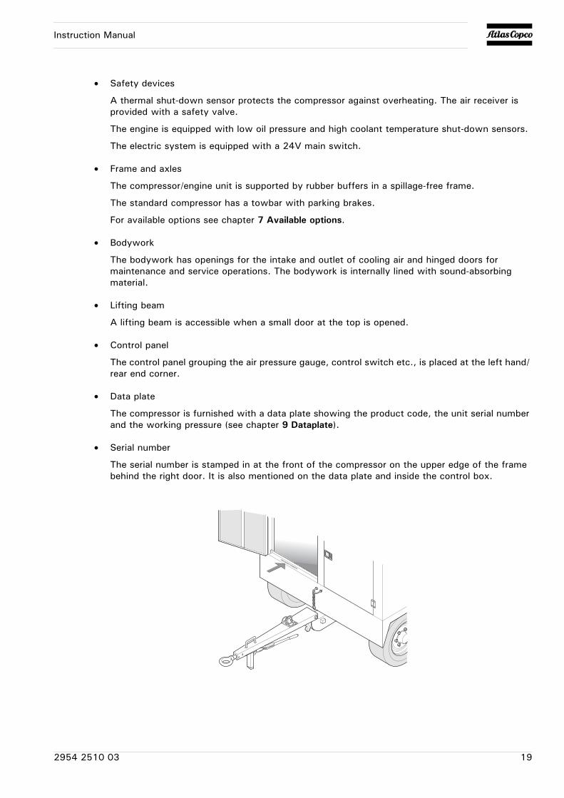
• Serial number
The serial number is stamped in at the front of the compressor on the upper edge of the frame behind the right door. It is also mentioned on the data plate and inside the control box.
2954 2510 03 19
Instruction Manual
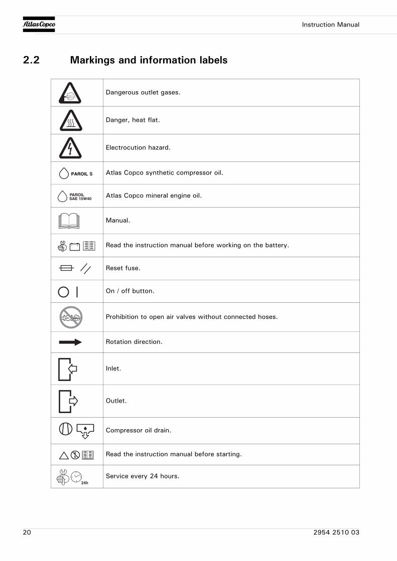
2.2 Markings and information labels
Dangerous outlet gases.
Danger, heat flat.
Electrocution hazard.
Atlas Copco synthetic compressor oil.
Atlas Copco mineral engine oil.
Manual.
Read the instruction manual before working on the battery.
Reset fuse.
On / off button.
Prohibition to open air valves without connected hoses.
Rotation direction.
Inlet.
Outlet.
Compressor oil drain.
Read the instruction manual before starting.
Service every 24 hours.
20 2954 2510 03
Instruction Manual
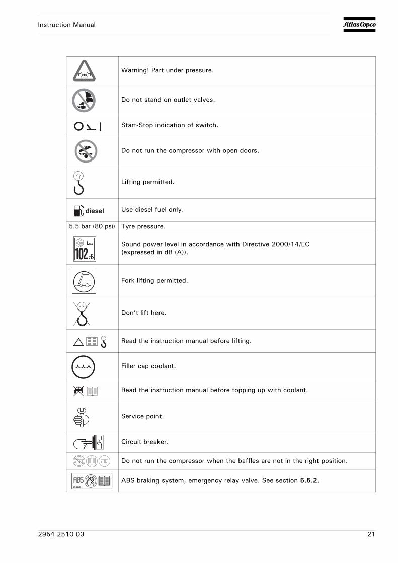
Warning! Part under pressure.
Do not stand on outlet valves.
Start-Stop indication of switch.
Do not run the compressor with open doors.
Lifting permitted.
Use diesel fuel only.
5.5 bar (80 psi) Tyre pressure.
Sound power level in accordance with Directive 2000/14/EC (expressed in dB (A)).
Fork lifting permitted.
Don’t lift here.
Read the instruction manual before lifting.
Filler cap coolant.
Read the instruction manual before topping up with coolant.
Service point.
Circuit breaker.
Do not run the compressor when the baffles are not in the right position.
ABS braking system, emergency relay valve. See section 5.5.2.
2954 2510 03 21
Instruction Manual
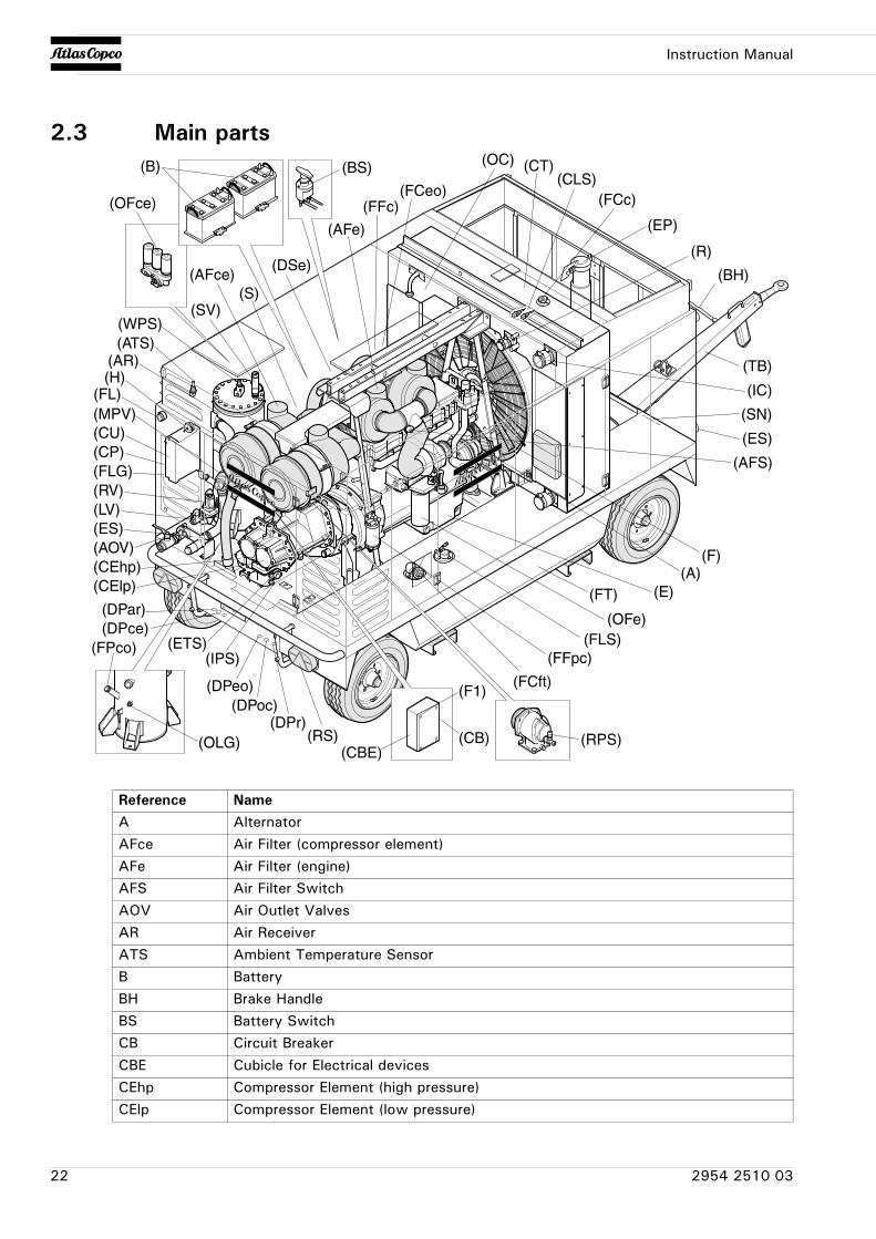
2.3 Main parts
(AFce)
(AFe)
(AOV)
(AR)
(CElp)(CEhp)
(R)
(E)
(EP)
(ES)
(F)
(OFe)
(FT)
(IC)
(FCc)
(LV)
(MPV)
(OC)
(OFce)
(OLG)
(RV)
(SV)
(AFS)
(B)
(FFpc)
(ES)
(FPco)
(RS)
(WPS)
(FCft)
(CU)(CP)(FLG)
(S)
(A)
(FFc)
(DSe)
(FCeo)
(BH)
(TB)
(CBE)(CB)
(F1)
(SN)
(RPS)
(FLS)
(CT)(CLS)
(DPeo)(DPoc)
(DPr)
(DPce)(DPar)
(ETS)(IPS)
(ATS)
(H)(FL)
(BS)
Reference NameA AlternatorAFce Air Filter (compressor element)AFe Air Filter (engine)AFS Air Filter SwitchAOV Air Outlet ValvesAR Air ReceiverATS Ambient Temperature SensorB BatteryBH Brake HandleBS Battery SwitchCB Circuit BreakerCBE Cubicle for Electrical devicesCEhp Compressor Element (high pressure)CElp Compressor Element (low pressure)
22 2954 2510 03
Instruction Manual
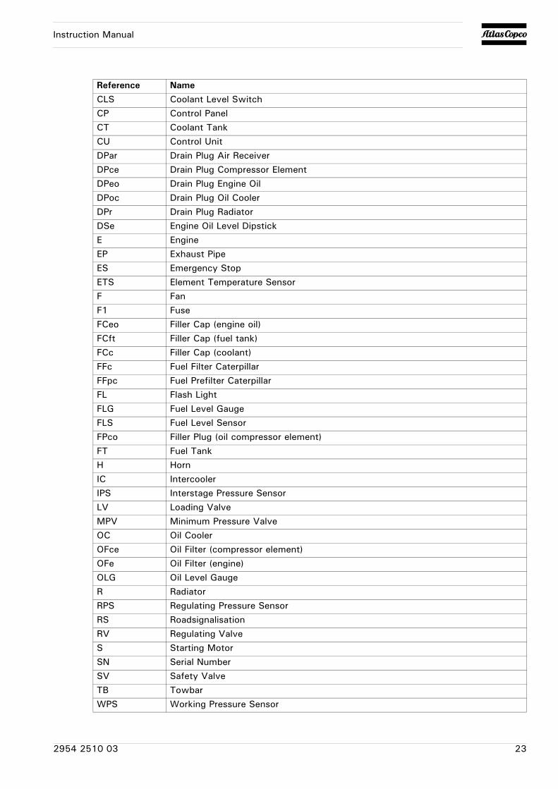
CLS Coolant Level SwitchCP Control PanelCT Coolant TankCU Control UnitDPar Drain Plug Air ReceiverDPce Drain Plug Compressor ElementDPeo Drain Plug Engine OilDPoc Drain Plug Oil CoolerDPr Drain Plug RadiatorDSe Engine Oil Level DipstickE EngineEP Exhaust PipeES Emergency StopETS Element Temperature SensorF FanF1 FuseFCeo Filler Cap (engine oil)FCft Filler Cap (fuel tank)FCc Filler Cap (coolant)FFc Fuel Filter CaterpillarFFpc Fuel Prefilter CaterpillarFL Flash LightFLG Fuel Level GaugeFLS Fuel Level SensorFPco Filler Plug (oil compressor element)FT Fuel TankH HornIC IntercoolerIPS Interstage Pressure SensorLV Loading ValveMPV Minimum Pressure ValveOC Oil CoolerOFce Oil Filter (compressor element)OFe Oil Filter (engine)OLG Oil Level GaugeR RadiatorRPS Regulating Pressure SensorRS RoadsignalisationRV Regulating ValveS Starting MotorSN Serial NumberSV Safety ValveTB TowbarWPS Working Pressure Sensor
Reference Name
2954 2510 03 23
Instruction Manual
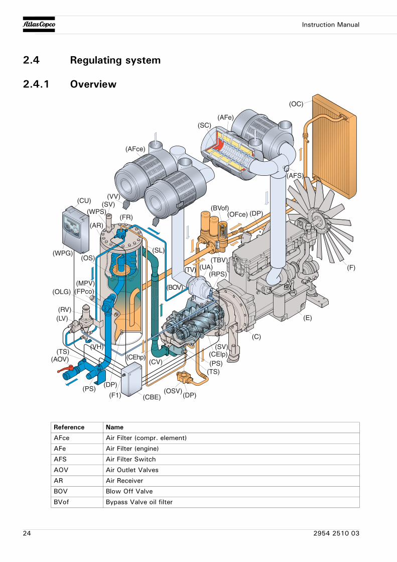
2.4 Regulating system
2.4.1 Overview
(AFS)
(DP)
(TBV)
(E)
(F)
(C)
(UA)
(BOV)
(OC)
(OSV)
(MPV)
(SV)(CU)
(TV)
(OLG) (FPco)
(CEhp) (CElp)
(FR)
(OS)
(AR)
(RV)(LV)
(SC)
(CV)
(RPS)
(AFce)
(AFe)
(AOV)
(SL)
(SV)
(WPS)
(WPG)
(TS)
(TS)
(DP)
(DP)
(VH)
(PS)
(PS)
(CBE)(F1)
(BVof)(OFce)
(VV)
Reference Name
AFce Air Filter (compr. element)
AFe Air Filter (engine)
AFS Air Filter Switch
AOV Air Outlet Valves
AR Air Receiver
BOV Blow Off Valve
BVof Bypass Valve oil filter
24 2954 2510 03
Instruction Manual
C Coupling
CBE Cubicle for Electrical devices
CEhp Compressor Element (high pressure)
CElp Compressor Element (low pressure)
CU Control Unit
CV Check Valve
DP Drain Plug
E Engine
F Fan
F1 Fuse
FPco Filler Plug (oil compressor element)
FR Flow Restrictor
LV Loading Valve
MPV Minimum Pressure Valve
OC Oil Cooler
OFce Oil Filter (compressor element)
OLG Oil Level Gauge
OS Oil Separator
OSV Oil Stop Valve
PS Pressure Sensor
RPS Regulating Pressure Sensor
RV Regulating Valve
SC Safety Cartridge
SL Scavenge Line
SV Safety Valve
TBV Thermostatic Bypass Valve
TS Temperature Sensor
TV Throttle Valve
UA Unloader Assembly
VH Vent hole
VV Vacuator Valve
WPG Working Pressure Gauge
WPS Working Pressure Sensor
Reference Name
2954 2510 03 25
Instruction Manual
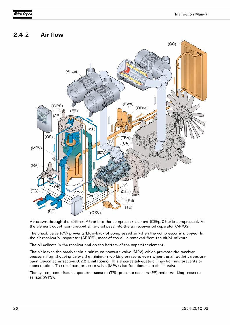
2.4.2 Air flow
Air drawn through the airfilter (AFce) into the compressor element (CEhp CElp) is compressed. At the element outlet, compressed air and oil pass into the air receiver/oil separator (AR/OS).
The check valve (CV) prevents blow-back of compressed air when the compressor is stopped. In the air receiver/oil separator (AR/OS), most of the oil is removed from the air/oil mixture.
The oil collects in the receiver and on the bottom of the separator element.
The air leaves the receiver via a minimum pressure valve (MPV) which prevents the receiver pressure from dropping below the minimum working pressure, even when the air outlet valves are open (specified in section 8.2.2 Limitations). This ensures adequate oil injection and prevents oil consumption. The minimum pressure valve (MPV) also functions as a check valve.
The system comprises temperature sensors (TS), pressure sensors (PS) and a working pressure sensor (WPS).
(CElp)
(OS)
(AR)
(AFce)
(TS)
(TS)
(PS)
(PS)
(MPV)
(CV)
(WPS)
(OSV)
(FR)
(SL)
(TBV)
(BVof)(OFce)
(OC)
(CEhp)
(UA)
(BOV)
(TV)
(RV)
(VH)
26 2954 2510 03
Instruction Manual
2.4.3 Oil systemThe lower part of the air receiver (AR) serves as oil tank.
Air pressure forces the oil from the air receiver/oil separator (AR/OS) through the oil cooler (OC), the oil filters (OF) and the oil stop valve (OSV) to the compressor element (CEhp CElp).
When the compressor is stopped and / or there is no pressure in the system, the oil stop valve (OSV) prevents the oil from flowing back into the compressor element.
The thermostatic by-pass valve (TBV) starts opening when the oil temperature is 80 °C (176 °F) (when no Oiltronix is installed). With installed Oiltronix, the thermostatic by-pass valve starts opening when the oil temperature is 40 °C (104 °F).
The compressor element has an oil gallery in the bottom of its casing. The oil for rotor lubrication, cooling and sealing is injected through holes in the gallery.
Lubrication of the bearings is ensured by oil injected into the bearing housings.
The injected oil, mixed with the compressed air, leaves the compressor element and re-enters the air receiver, where it is separated from the air as described in section 2.4.2 Air flow. The oil that collects in the bottom of the oil separator element is returned to the system through a scavenging line (SL), which is provided with a flow restrictor (FR).
The oil filter by-pass valve opens when the pressure drop over the filter is above normal because of a clogged filter. The oil then by-passes the filter without being filtered. For this reason, the oil filter must be replaced at regular intervals (see section 4.5 Preventive maintenance schedule for the compressor).
2.4.4 Continuous regulating systemThe compressor is provided with a continuous regulating system and a blow-off valve (BOV) which is integrated in the unloader assembly (UA). The valve is closed during operation by outlet pressure of the compressor element and opens by air receiver pressure when the compressor is stopped.When the air consumption increases, the air receiver pressure will decrease and vice versa. This receiver pressure variation is sensed by the regulating valve (RV) which, by means of control air to the unloader assembly (UA), matches the air output to the air consumption. The air receiver pressure is maintained between the pre-selected working pressure and the corresponding unloading pressure.When starting the compressor, the throttle valve (TV) is kept closed via receiver pressure. The compressor element (CEhp CElp) takes in air and pressure builds up in the receiver (AR). The throttle valve (TV) is closed. The air output is controlled from maximum output (100%) to no output (0%) by:
1 Speed control of the engine between maximum load speed and unloading speed (the output of a screw compressor is proportional to the rotating speed).
2 Air inlet throttling.
If the air consumption is equal to or exceeds the maximum air output, the engine speed is held at maximum load speed and the throttle valve (TV) is fully open.If the air consumption is less than the maximum air output, air receiver pressure increases and the regulating valve supplies control air to throttle valve (TV) to reduce the air output and holds air receiver pressure between the normal working pressure and the corresponding unloading pressure. Unloading pressure = normal working pressure + 1 bar (14.504 psi).When the air consumption is resumed, the blow off valve (BOV) closes and the throttle valve (TV) gradually opens the air intake and the electronic speed regulator increases the engine speed.The construction of the regulating valve (RV) is such that any increase (decrease) of the air receiver pressure above the pre-set valve opening pressure results in a proportional increase (decrease) of the control pressure to the throttle valve and the electronic speed regulator.Part of the control air is vented to atmosphere, and any condensate discharged, through the vent holes (VH).
2954 2510 03 27
Instruction Manual
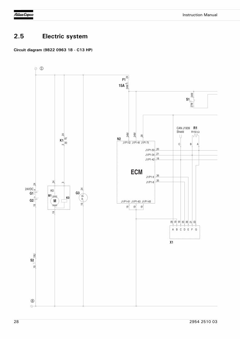
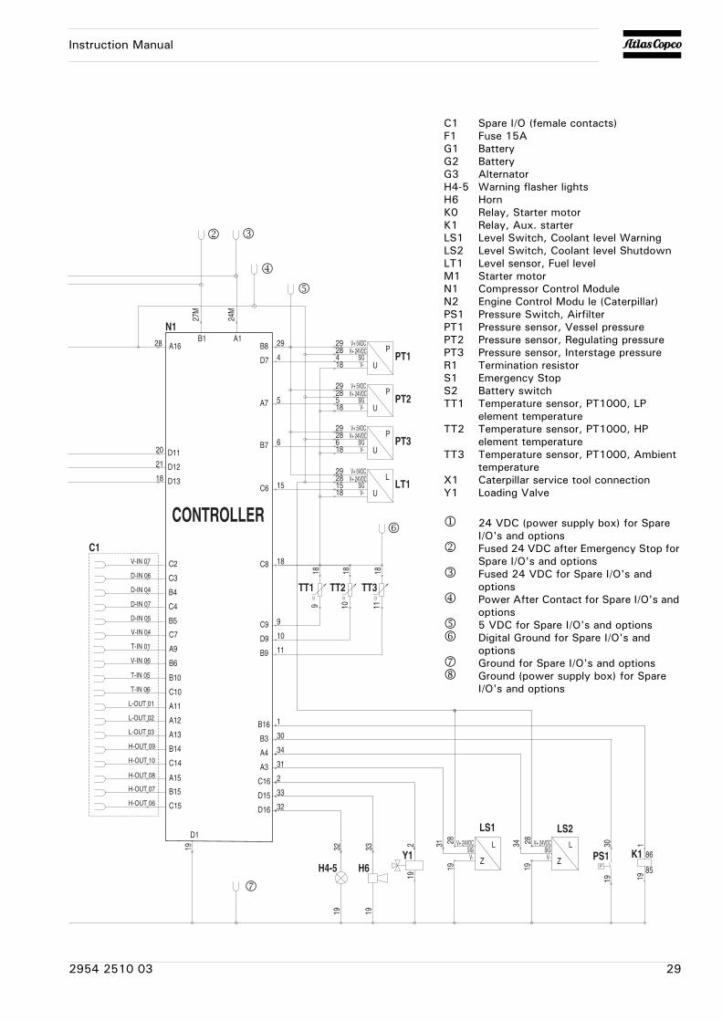
2.5 Electric system
Circuit diagram (9822 0963 18 - C13 HP)
+-G1+
-G2K0
MM1
K0
B-B+
G3
S1
24
24
24
2424
M24
M
24M
3
19
S2
1919
U
19
19
28
20
21
18
36
35
1919 19
28 19 18 35 36 21 20
24VDC
K1 87
30
24M
3
ECM
J1/P1-52 J1/P1-70
J1/P1-50
J1/P1-34
J1/P1-42
J1/P1-9
J1/P1-8
J1/P1-61 J1/P1-63 J1/P1-65
N2J1/P1-48
24
27M
X1
F1
15A
1
8
A B C
C B A
D E F G
R1
28 2954 2510 03
Instruction Manual
TT1
P
U
V+ 24VDCV+ 5VDC
V-SIG
24M
19
28
20
21
18
18
18
29
184
9
5 5
4
K1 86
85
TT2
18
10
9 10
191
1
27M
Y1 PS1
LS1
19
19 19
30
34
31
2
3431 28 282 3019
CONTROLLER
A16
B3
C8
B8
D7
D11
D12
D13
A1B1
C16
A4
A3
B16
A7
C9
N1
C7 D911B9A9
D1
D16
D15
C6
C2
C3
B4
C4
B5
B6
B10
C10
A11
A12
A13
B14
C14
B15
C15
LS2
19 19
H4-5 H6
32 33
33
32
2928
18
2928
PT1
P
U
V+ 24VDCV+ 5VDC
V-SIG
V+ 24VDC
V-SIG
V+ 24VDC
V-SIG
PT2
6 6B7 18
2928 P
U
V+ 24VDCV+ 5VDC
V-SIG PT3
18
2928 L
U
L
Z
L
Z
V+ 24VDCV+ 5VDC
V-SIG LT11515
V-IN 07
D-IN 06
D-IN 04
D-IN 07
D-IN 05
V-IN 06
T-IN 05
T-IN 06
L-OUT 01
L-OUT 02
L-OUT 03
H-OUT 09
H-OUT 10
H-OUT 07
A15H-OUT 08
H-OUT 06
C1
V-IN 04
T-IN 01
2 3
4
5
TT3
1811
6
7
C1 Spare I/O (female contacts)F1 Fuse 15AG1 BatteryG2 BatteryG3 AlternatorH4-5 Warning flasher lightsH6 HornK0 Relay, Starter motorK1 Relay, Aux. starter LS1 Level Switch, Coolant level WarningLS2 Level Switch, Coolant level ShutdownLT1 Level sensor, Fuel levelM1 Starter motorN1 Compressor Control ModuleN2 Engine Control Modu le (Caterpillar)PS1 Pressure Switch, AirfilterPT1 Pressure sensor, Vessel pressurePT2 Pressure sensor, Regulating pressurePT3 Pressure sensor, Interstage pressureR1 Termination resistorS1 Emergency StopS2 Battery switchTT1 Temperature sensor, PT1000, LP
element temperatureTT2 Temperature sensor, PT1000, HP
element temperatureTT3 Temperature sensor, PT1000, Ambient
temperatureX1 Caterpillar service tool connectionY1 Loading Valve
1 24 VDC (power supply box) for Spare I/O's and options
2 Fused 24 VDC after Emergency Stop for Spare I/O's and options
3 Fused 24 VDC for Spare I/O's and options
4 Power After Contact for Spare I/O's and options
5 5 VDC for Spare I/O's and options6 Digital Ground for Spare I/O's and
options7 Ground for Spare I/O's and options8 Ground (power supply box) for Spare
I/O's and options
2954 2510 03 29
Instruction Manual
3 Operating instructions
3.1 Parking, towing and lifting instructions
Safety precautions
Attention
The operator is expected to apply all relevant 1 Safety precautions.
• Before putting the compressor in to use, check the brake system as described in section 5.5.1 Brake shoe adjustment (no ABS).
• After the first 100 km travel:
Check and retighten the wheel nuts and towbar bolts to the specified torque. See section 8.1 Torque values.
Check the brake adjustment. See section 5.5.1 Brake shoe adjustment (no ABS).
When towing, lifting or transporting the compressor in any way, the battery switch must always be in the “OFF” position!
30 2954 2510 03
Instruction Manual
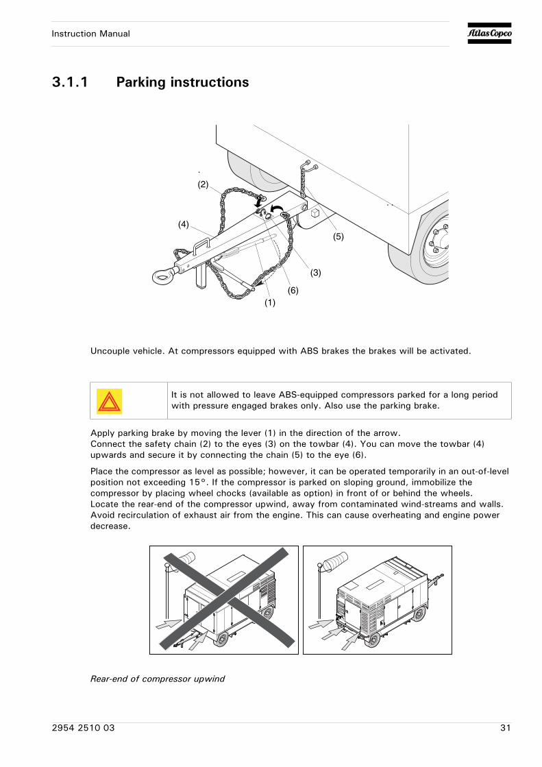
3.1.1 Parking instructions
Uncouple vehicle. At compressors equipped with ABS brakes the brakes will be activated.
Apply parking brake by moving the lever (1) in the direction of the arrow.Connect the safety chain (2) to the eyes (3) on the towbar (4). You can move the towbar (4) upwards and secure it by connecting the chain (5) to the eye (6).
Place the compressor as level as possible; however, it can be operated temporarily in an out-of-level position not exceeding 15°. If the compressor is parked on sloping ground, immobilize the compressor by placing wheel chocks (available as option) in front of or behind the wheels.Locate the rear-end of the compressor upwind, away from contaminated wind-streams and walls. Avoid recirculation of exhaust air from the engine. This can cause overheating and engine power decrease.
Rear-end of compressor upwind
(1)(6)
(3)
(5)
(2)
(4)
It is not allowed to leave ABS-equipped compressors parked for a long period with pressure engaged brakes only. Also use the parking brake.
2954 2510 03 31
Instruction Manual
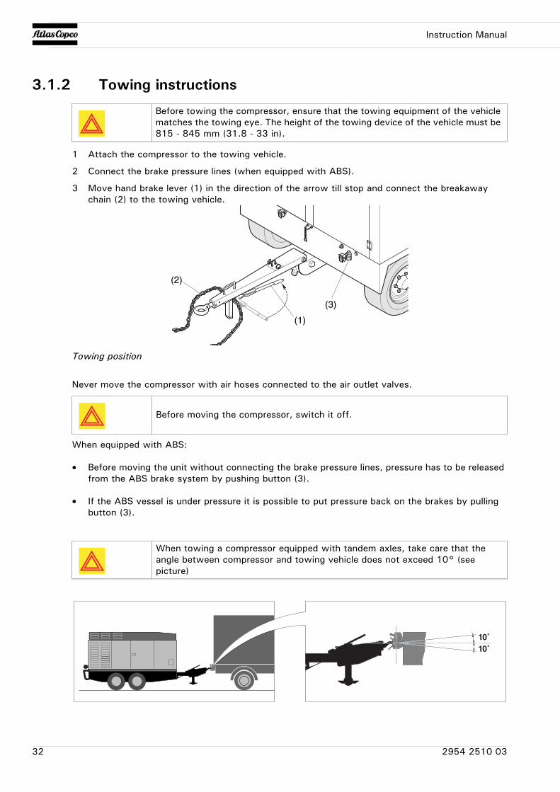
3.1.2 Towing instructions
1 Attach the compressor to the towing vehicle.
2 Connect the brake pressure lines (when equipped with ABS).
3 Move hand brake lever (1) in the direction of the arrow till stop and connect the breakaway chain (2) to the towing vehicle.
Towing position
Never move the compressor with air hoses connected to the air outlet valves.
When equipped with ABS:
• Before moving the unit without connecting the brake pressure lines, pressure has to be released from the ABS brake system by pushing button (3).
• If the ABS vessel is under pressure it is possible to put pressure back on the brakes by pulling button (3).
Before towing the compressor, ensure that the towing equipment of the vehicle matches the towing eye. The height of the towing device of the vehicle must be 815 - 845 mm (31.8 - 33 in).
Before moving the compressor, switch it off.
When towing a compressor equipped with tandem axles, take care that the angle between compressor and towing vehicle does not exceed 10° (see picture)
(1)
(3)
(2)
10˚10˚
32 2954 2510 03
Instruction Manual
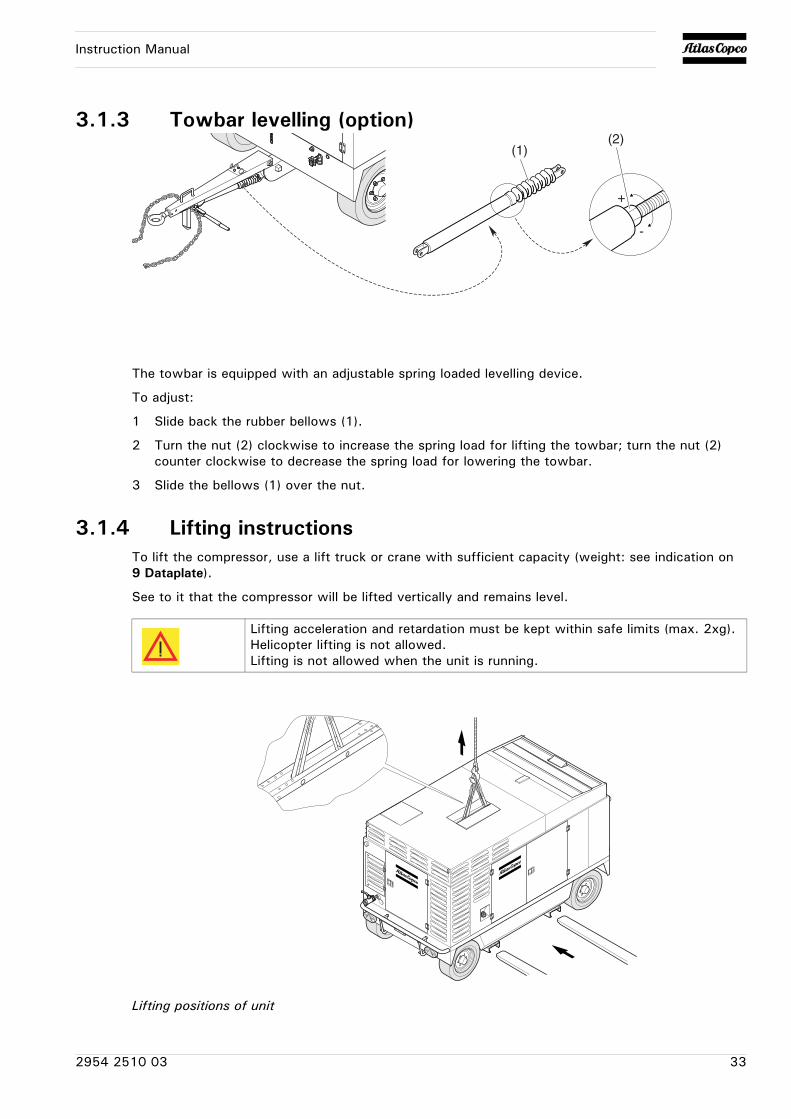
3.1.3 Towbar levelling (option)
The towbar is equipped with an adjustable spring loaded levelling device.
To adjust:
1 Slide back the rubber bellows (1).
2 Turn the nut (2) clockwise to increase the spring load for lifting the towbar; turn the nut (2) counter clockwise to decrease the spring load for lowering the towbar.
3 Slide the bellows (1) over the nut.
3.1.4 Lifting instructionsTo lift the compressor, use a lift truck or crane with sufficient capacity (weight: see indication on 9 Dataplate).
See to it that the compressor will be lifted vertically and remains level.
Lifting positions of unit
+
-
(2)(1)
Lifting acceleration and retardation must be kept within safe limits (max. 2xg).Helicopter lifting is not allowed.Lifting is not allowed when the unit is running.
2954 2510 03 33
Instruction Manual
3.2 Preheater (option)
3.2.1 Description heating operationWhen switched on the signal lamp in the mini-clock control element is lit. The waterpump starts and after a fixed programme with prerinsing and preheating, combustion air fan, glow plug and fuel dosing pump set combustion going. Once a stable flame has formed, the glow plug is switched off by a timer.
Depending on the heat requirement, the heater wil switch between three levels, LARGE, SMALL and OFF (control interval). The temperature thresholds have been fixed programmed in the electronic control device. If the heat requirement at level SMALL is so low that the cooling water temperature reaches 85°C (185°F), the device goes into control interval. This is followed by the fan continuing to run for about 130 sec. The signal lamp will stay lit during the control interval and also the waterpump continues to run.
If the heater does not ignite within 90 seconds after fuel pumping has started, the start procedure must be repeated. If the heater once again fails to ignite after 90 seconds a fault shut down is effected.
It is possible to override a fault shut-down by briefly switching the heater off and then on again.
When an emergency stop has to be performed:
• Switch off the preheater at the control element
• Remove the fuse or disconnect the heater from the battery
Safety procedure before starting after a longer period of standstill
Check whether the fuse is in its place and / or the wiring is connected to the battery.
Check if all parts are firmly fixed.
Check the fuel system visualy on leaks.
Preheater altitude capability
Up to 1.500 meters no restrictions
Above 1.500 meters Operation possible for short periods
Continuous operation NOT possible
Do not repeat this more than twice in succesion!
34 2954 2510 03
Instruction Manual
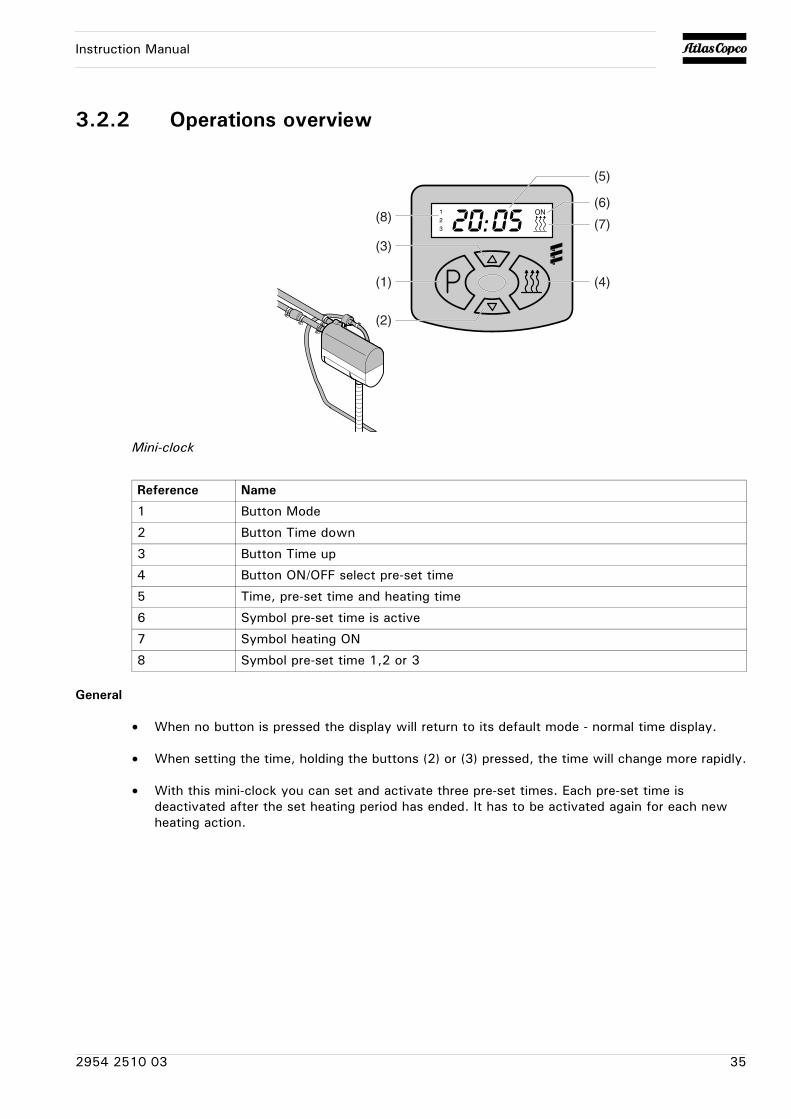
3.2.2 Operations overview
Mini-clock
General
• When no button is pressed the display will return to its default mode - normal time display.
• When setting the time, holding the buttons (2) or (3) pressed, the time will change more rapidly.
• With this mini-clock you can set and activate three pre-set times. Each pre-set time is deactivated after the set heating period has ended. It has to be activated again for each new heating action.
(5)
(6)
(7)
(4)
(8)
(3)
(1)
(2)
Reference Name
1 Button Mode
2 Button Time down
3 Button Time up
4 Button ON/OFF select pre-set time
5 Time, pre-set time and heating time
6 Symbol pre-set time is active
7 Symbol heating ON
8 Symbol pre-set time 1,2 or 3
2954 2510 03 35
Instruction Manual
Settings
Commisioning
After connecting the power all symbols in the display will blink. Now the actual time has to be set before the heater can be operated.
Press button (1); time blinks. Set time with buttons (2) or (3).
Press button (1); time is displayed, colon blinks.
Setting the time
Press button (1) longer then 3 sec.; time blinks. Set with buttons (2) or (3). Briefly press button (1); time is displayed, colon blinks.
Setting heating period
Press button (1) longer then 3 sec.; time blinks. Wait till the display indicates "setting heating period"; heating symbol and time blink. Set heating period (10 to 120 min) using button (2) or (3). Press button (1); time is displayed, colon blinks.
Setting pre-settings
By pressing button (1) once, twice or three times you will select pre-set time 1, 2 or 3.
The display shows e.g. pre-set time 1 and symbol 1. Set the pre-set period with buttons (2) or (3).
With button (4) you can activate or deactivate the pre-set period. When activated the symbol "ON" appears and the symbol "1, 2 or 3".
Operation
Switching ON the heater
Press button (4). The heating period lasts ..minutes. The display shows: remaining heating time and symbol 7.
Switching OFF the heater
Press button (4). The heater will run idle for about 3 minutes. The display shows: actual time.
Continuous operation
Press and hold button (3), then press button (4); now the heater will be operating till button (4) (heater off) is pressed.
Activating/ deactivating pre-set time
Select pre-set time 1, 2 or 3 by pressing button (1).
Activate the selected time by pressing button (4).
The display shows: symbol "ON" as well as the selected pre-set time, "1, 2 or 3".
If you do not press the button within 5 seconds the mode is changed to “setting heating period”.
36 2954 2510 03
Instruction Manual
Problem solving
Problem: Heater does not start when switched on.
Problem: Flame extinghuises.
Problem: Heater shuts off.
Problem: Control unit locked.
Possible faults Corrective actions
No fuel. Check fuel level.
Fuse blown. Check fuse.
Bad electrical contact. Check electrical wiring.
Blocked air duct or exhaust gas duct. Check combustion air duct and exhaust gas duct.
Glow plug defective. Replace glow plug.
Fan motor defective. Replace fan motor.
Possible faults Corrective actions
Overheating Cool down and start again.
Possible faults Corrective actions
Upper or lower voltage limit is reached. Check power.
Possible faults Corrective actions
Device switched off and on again too many times.
Contact your agent.
2954 2510 03 37
Instruction Manual
3.3 Before startingStep Action
1. Before initial start-up, prepare battery for operation if not already done. See section 4.13.3 Recharging a battery.
2. Check that the draining caps in the spillage-free frame are firmly tightened.
3. With the compressor standing level, check the level of the engine oil. Add oil, if necessary, to the upper mark on dipstick. Also check the engine coolant level. Consult the Engine Operation Manual for the type of coolant and type and viscosity grade of the engine oil.
4. Remove the air receiver drain plug (DPar), see figure at step 12., and open the valve to drain possible condensate. Close the valve when oil comes out and reinstall the drain plug. The interval between draining operations may be determined by experience, as the amount of condensate depends on the operating condition.
Before draining, ensure that the pressure is released.
5. Check the level of the compressor oil. See section 4.7.2 Check compressor oil level. The pointer of oil level gauge (OLG) should register in the green range. Add oil if necessary. See section 4.6.1 Compressor oil for the oil to be used.
Before removing oil filler plug (FP), ensure that the pressure is released by opening an air outlet valve.
6. Check that the fuel tank contains sufficient fuel. Top up, if necessary. Consult the Engine Operation Manual for the type of fuel.
7. Drain any water and sediment from the fuel filters until clean fuel flows from the drain cock.
8. Empty the dust trap of each air filter (AF). See section 5.2.3 Replacing the filter element and the safety cartridge.
9. Clogged air filter(s) will be indicated on the display of the control panel, see section 3.4.9 Fault codes. If indicated, replace the filter elements.
10. Check coolant level in engine coolant top tank integrated in radiator. Top up, if necessary. Consult the Engine Operation Manual for coolant specifications.
11. Check that the battery switch is “ON”. The battery switch may only be switched off after the control unit has been switched off.
38 2954 2510 03
Instruction Manual
3.4 Starting / Stopping
Safety precautions
Make sure the fuel tank is filled up.
Step Action
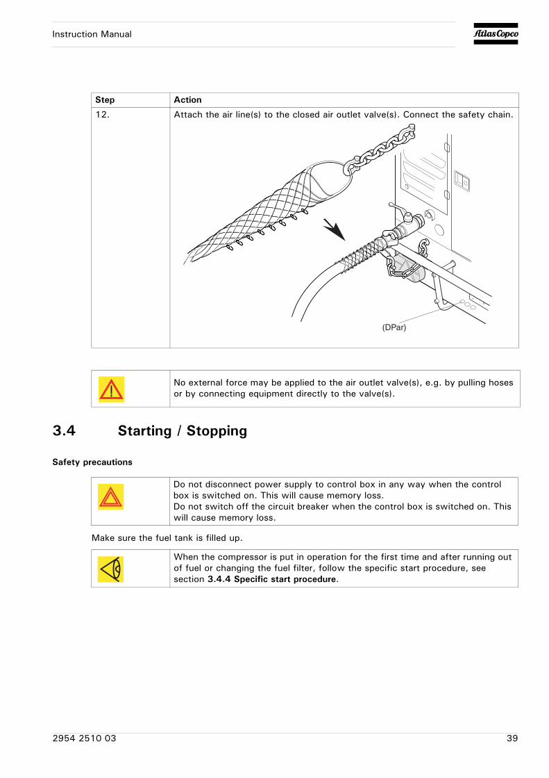
12. Attach the air line(s) to the closed air outlet valve(s). Connect the safety chain.
No external force may be applied to the air outlet valve(s), e.g. by pulling hoses or by connecting equipment directly to the valve(s).
(DPar)
Do not disconnect power supply to control box in any way when the control box is switched on. This will cause memory loss.Do not switch off the circuit breaker when the control box is switched on. This will cause memory loss.
When the compressor is put in operation for the first time and after running out of fuel or changing the fuel filter, follow the specific start procedure, see section 3.4.4 Specific start procedure.
2954 2510 03 39
Instruction Manual
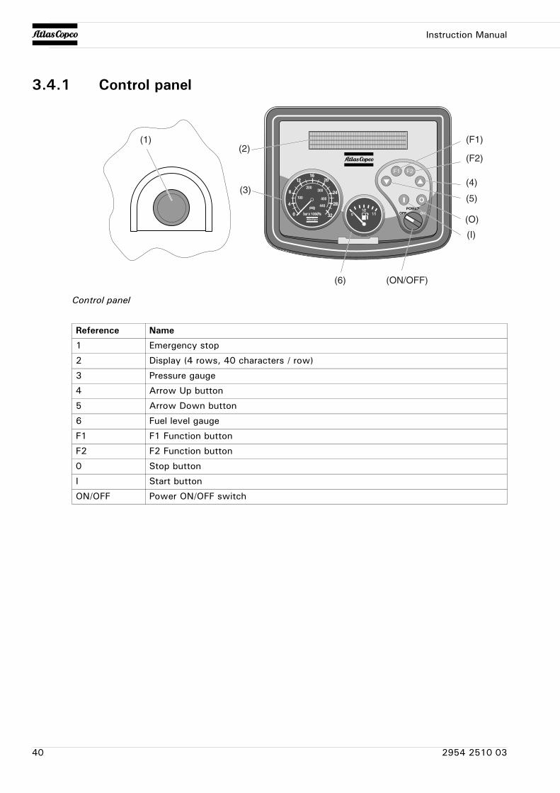
3.4.1 Control panel
Control panel
(1)(2)
(3)(4)
(5)
(F1)
(F2)
(6)
(O)
(I)
(ON/OFF)
Reference Name
1 Emergency stop
2 Display (4 rows, 40 characters / row)
3 Pressure gauge
4 Arrow Up button
5 Arrow Down button
6 Fuel level gauge
F1 F1 Function button
F2 F2 Function button
0 Stop button
I Start button
ON/OFF Power ON/OFF switch
40 2954 2510 03
Instruction Manual
3.4.2 Operations overviewIt is possible to control the compressor locally with the Control Box, remotely with the remote switch inputs located on the back of the Control Box, or with software running on a PC with a CAN interface (PC Control Mode).
The way one ends up in each status can differ from how the Control Box is controlled, but the function of each status stays the same.
When reading this document, mind the difference between a status and a procedure. A status is a state in the Control Box's operation. A procedure is an action executed by the Control Box.
Example: The Stopping procedure is executed in the Stopping status, the Start Failure status and the Shutdown status.
During operation
Regularly carry out following checks:
1 That the regulating valve (RV) is correctly adjusted, i.e. starts decreasing the engine speed when reaching the preset working pressure in the receiver.
2 Check the air outlet temperature of the compressor element.
3 Check the engine oil pressure, the coolant temperature and display of control box.
4 Avoid the engine running out of fuel. Nevertheless, if this happens, fill the fuel tank and prime the fuel system to speed up starting (see section 3.4.4 Specific start procedure).
3.4.3 Battery switchThe compressor is equipped with a battery switch.
When the compressor is not in use this switch must always be in the “OFF” position.
It is not allowed to use this switch as an emergency switch or for stopping the compressor. It will cause damage in the control unit when using this switch for stopping.
Always first shut off the control unit and wait until the display is dark before switching the battery switch to position “OFF”.
When the engine is running, the air outlet valves (ball valves) must always be put in a fully opened or fully closed position.
The doors must be closed during operation and may be opened for short periods for inspection and adjustments only.
2954 2510 03 41
Instruction Manual
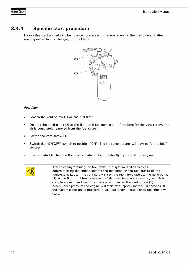
3.4.4 Specific start procedureFollow this start procedure when the compressor is put in operation for the first time and after running out of fuel or changing the fuel filter.
Fuel filter
• Loosen the vent screw (1) on the fuel filter.
• Operate the hand pump (2) at the filter until fuel comes out of the bore for the vent screw, and air is completely removed from the fuel system.
• Fasten the vent screw (1).
• Switch the “ON/OFF” switch to position ”ON”. The instrument panel will now perform a brief selftest.
• Push the start button and the starter motor will automatically try to start the engine.
After cleaning/draining the fuel tanks, the system is filled with air.Before starting the engine operate the fuelpump on the fuelfilter to fill the fuelsystem. Loosen the vent screw (1) on the fuel filter. Operate the hand pump (2) at the filter until fuel comes out of the bore for the vent screw, and air is completely removed from the fuel system. Fasten the vent screw (1).When under pressure the engine will start after approximately 10 seconds. If the system is not under pressure, it will take a few minutes untill the engine will start.
(1)
(2)
42 2954 2510 03

Instruction Manual
3.4.5 Power ON / OFF
Switch on the battery switch.
Switch the machine on by switching the “ON/OFF” switch to the position “ON”. The instrument panel will now perform a brief selftest.
The display will show:
By pressing the button “F1”, the user goes to the INFO status.
(F1)
(ON/OFF)
Do not disconnect power supply during operation.When disconnecting power supply during operation the user will be prompted to this by the next display.
2954 2510 03 43
Instruction Manual
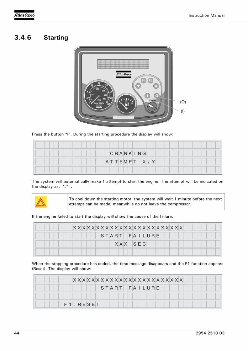
3.4.6 Starting
Press the button “I”. During the starting procedure the display will show:
The system will automatically make 1 attempt to start the engine. The attempt will be indicated on the display as: '1/1'.
If the engine failed to start the display will show the cause of the failure:
When the stopping procedure has ended, the time message disappears and the F1 function appears (Reset). The display will show:
(O)
(I)
To cool down the starting motor, the system will wait 1 minute before the next attempt can be made, meanwhile do not leave the compressor.
44 2954 2510 03
Instruction Manual
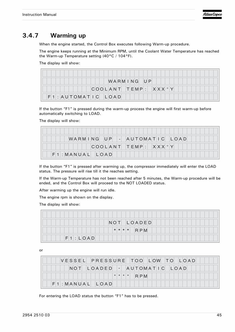
3.4.7 Warming upWhen the engine started, the Control Box executes following Warm-up procedure.
The engine keeps running at the Minimum RPM, until the Coolant Water Temperature has reached the Warm-up Temperature setting (40°C / 104°F).
The display will show:
If the button “F1” is pressed during the warm-up process the engine will first warm-up before automatically switching to LOAD.
The display will show:
If the button “F1” is pressed after warming up, the compressor immediately will enter the LOAD status. The pressure will rise till it the reaches setting.
If the Warm-up Temperature has not been reached after 5 minutes, the Warm-up procedure will be ended, and the Control Box will proceed to the NOT LOADED status.
After warming up the engine will run idle.
The engine rpm is shown on the display.
The display will show:
or
For entering the LOAD status the button “F1” has to be pressed.
2954 2510 03 45
Instruction Manual
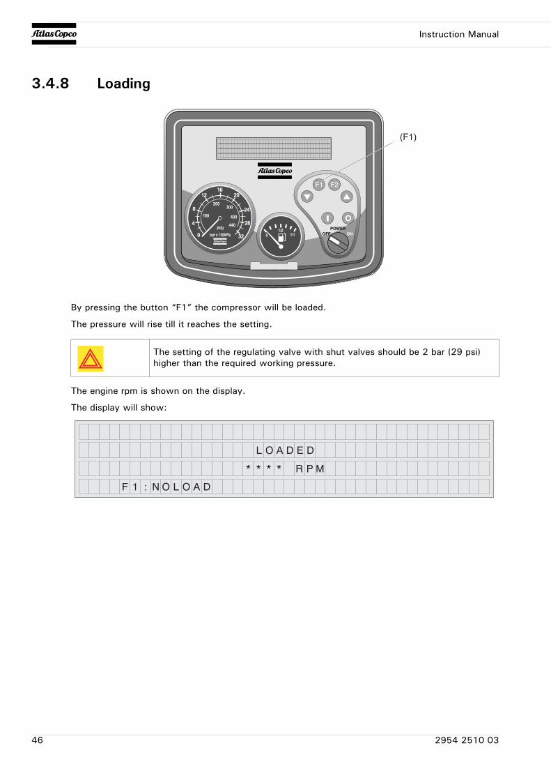
3.4.8 Loading
By pressing the button “F1” the compressor will be loaded.
The pressure will rise till it reaches the setting.
The engine rpm is shown on the display.
The display will show:
(F1)
The setting of the regulating valve with shut valves should be 2 bar (29 psi) higher than the required working pressure.
46 2954 2510 03
Instruction Manual
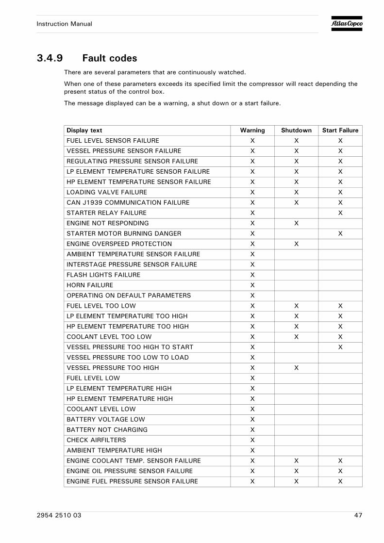
3.4.9 Fault codesThere are several parameters that are continuously watched.
When one of these parameters exceeds its specified limit the compressor will react depending the present status of the control box.
The message displayed can be a warning, a shut down or a start failure.
Display text Warning Shutdown Start Failure
FUEL LEVEL SENSOR FAILURE X X X
VESSEL PRESSURE SENSOR FAILURE X X X
REGULATING PRESSURE SENSOR FAILURE X X X
LP ELEMENT TEMPERATURE SENSOR FAILURE X X X
HP ELEMENT TEMPERATURE SENSOR FAILURE X X X
LOADING VALVE FAILURE X X X
CAN J1939 COMMUNICATION FAILURE X X X
STARTER RELAY FAILURE X X
ENGINE NOT RESPONDING X X
STARTER MOTOR BURNING DANGER X X
ENGINE OVERSPEED PROTECTION X X
AMBIENT TEMPERATURE SENSOR FAILURE X
INTERSTAGE PRESSURE SENSOR FAILURE X
FLASH LIGHTS FAILURE X
HORN FAILURE X
OPERATING ON DEFAULT PARAMETERS X
FUEL LEVEL TOO LOW X X X
LP ELEMENT TEMPERATURE TOO HIGH X X X
HP ELEMENT TEMPERATURE TOO HIGH X X X
COOLANT LEVEL TOO LOW X X X
VESSEL PRESSURE TOO HIGH TO START X X
VESSEL PRESSURE TOO LOW TO LOAD X
VESSEL PRESSURE TOO HIGH X X
FUEL LEVEL LOW X
LP ELEMENT TEMPERATURE HIGH X
HP ELEMENT TEMPERATURE HIGH X
COOLANT LEVEL LOW X
BATTERY VOLTAGE LOW X
BATTERY NOT CHARGING X
CHECK AIRFILTERS X
AMBIENT TEMPERATURE HIGH X
ENGINE COOLANT TEMP. SENSOR FAILURE X X X
ENGINE OIL PRESSURE SENSOR FAILURE X X X
ENGINE FUEL PRESSURE SENSOR FAILURE X X X
2954 2510 03 47
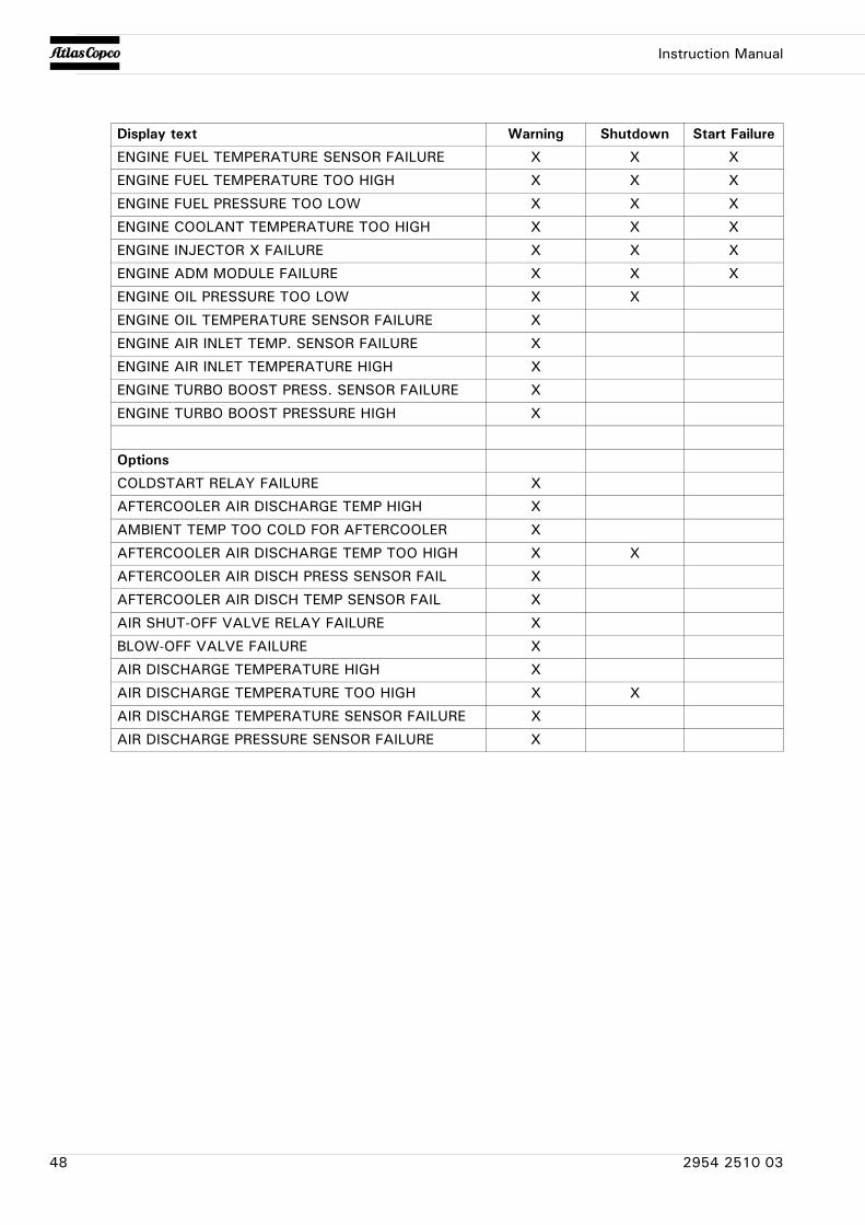
Instruction Manual
ENGINE FUEL TEMPERATURE SENSOR FAILURE X X X
ENGINE FUEL TEMPERATURE TOO HIGH X X X
ENGINE FUEL PRESSURE TOO LOW X X X
ENGINE COOLANT TEMPERATURE TOO HIGH X X X
ENGINE INJECTOR X FAILURE X X X
ENGINE ADM MODULE FAILURE X X X
ENGINE OIL PRESSURE TOO LOW X X
ENGINE OIL TEMPERATURE SENSOR FAILURE X
ENGINE AIR INLET TEMP. SENSOR FAILURE X
ENGINE AIR INLET TEMPERATURE HIGH X
ENGINE TURBO BOOST PRESS. SENSOR FAILURE X
ENGINE TURBO BOOST PRESSURE HIGH X
Options
COLDSTART RELAY FAILURE X
AFTERCOOLER AIR DISCHARGE TEMP HIGH X
AMBIENT TEMP TOO COLD FOR AFTERCOOLER X
AFTERCOOLER AIR DISCHARGE TEMP TOO HIGH X X
AFTERCOOLER AIR DISCH PRESS SENSOR FAIL X
AFTERCOOLER AIR DISCH TEMP SENSOR FAIL X
AIR SHUT-OFF VALVE RELAY FAILURE X
BLOW-OFF VALVE FAILURE X
AIR DISCHARGE TEMPERATURE HIGH X
AIR DISCHARGE TEMPERATURE TOO HIGH X X
AIR DISCHARGE TEMPERATURE SENSOR FAILURE X
AIR DISCHARGE PRESSURE SENSOR FAILURE X
Display text Warning Shutdown Start Failure
48 2954 2510 03
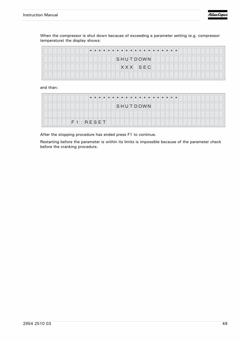
Instruction Manual
When the compressor is shut down because of exceeding a parameter setting (e.g. compressor temperature) the display shows:
and than:
After the stopping procedure has ended press F1 to continue.
Restarting before the parameter is within its limits is impossible because of the parameter check before the cranking procedure.
2954 2510 03 49

Instruction Manual
3.4.10 Stopping
To turn off the compressor first press the button “0”.
The engine will run some time at min. speed to cool down and will stop finally.
The remaining time is shown in the display:
Meanwhile the air receiver is depressurised.
Switch the “ON/OFF” switch to the position “OFF”.
Wait until the display is dark.
Switch the battery switch in the “OFF” position.
(O)
(ON/OFF)
50 2954 2510 03
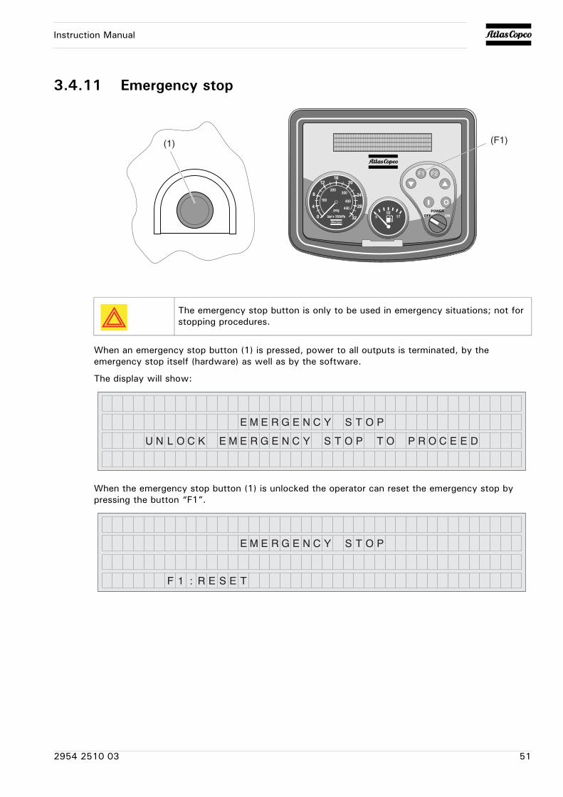
Instruction Manual
3.4.11 Emergency stop
When an emergency stop button (1) is pressed, power to all outputs is terminated, by the emergency stop itself (hardware) as well as by the software.
The display will show:
When the emergency stop button (1) is unlocked the operator can reset the emergency stop by pressing the button “F1”.
(1) (F1)
The emergency stop button is only to be used in emergency situations; not for stopping procedures.
2954 2510 03 51
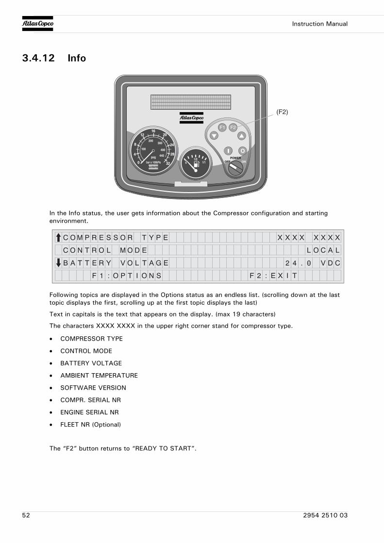
Instruction Manual
3.4.12 Info
In the Info status, the user gets information about the Compressor configuration and starting environment.
Following topics are displayed in the Options status as an endless list. (scrolling down at the last topic displays the first, scrolling up at the first topic displays the last)
Text in capitals is the text that appears on the display. (max 19 characters)
The characters XXXX XXXX in the upper right corner stand for compressor type.
• COMPRESSOR TYPE
• CONTROL MODE
• BATTERY VOLTAGE
• AMBIENT TEMPERATURE
• SOFTWARE VERSION
• COMPR. SERIAL NR
• ENGINE SERIAL NR
• FLEET NR (Optional)
The “F2” button returns to “READY TO START”.
(F2)
52 2954 2510 03
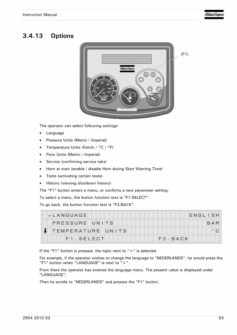
Instruction Manual
3.4.13 Options
The operator can select following settings:
• Language
• Pressure Units (Metric / Imperial)
• Temperature Units (Kelvin / °C / °F)
• Flow Units (Metric / Imperial)
• Service (confirming service taks)
• Horn at start (enable / disable Horn during Start Warning Time)
• Tests (activating certain tests)
• History (viewing shutdown history)
The “F1” button enters a menu, or confirms a new parameter setting.
To select a menu, the button function text is “F1:SELECT”.
To go back, the button function text is “F2:BACK”.
If the “F1” button is pressed, the topic next to ">" is selected.
For example, if the operator wishes to change the language to "NEDERLANDS", he would press the “F1” button when "LANGUAGE" is next to ">".
From there the operator has entered the language menu. The present value is displayed under “LANGUAGE”.
Then he scrolls to "NEDERLANDS" and presses the “F1” button.
(F1)
2954 2510 03 53
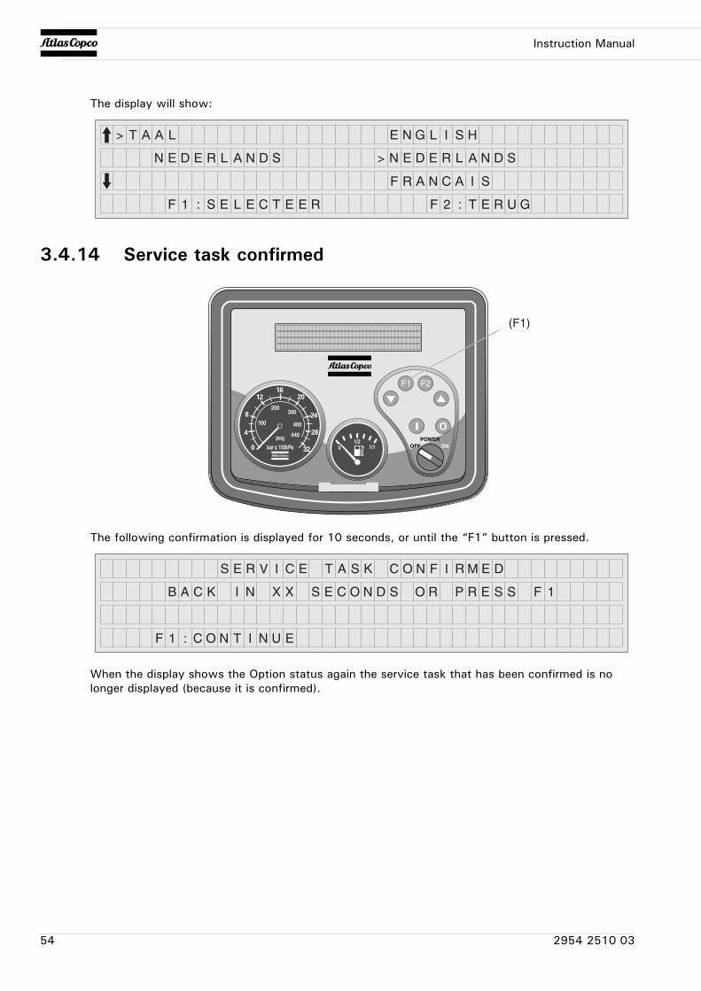
Instruction Manual
The display will show:
3.4.14 Service task confirmed
The following confirmation is displayed for 10 seconds, or until the “F1” button is pressed.
When the display shows the Option status again the service task that has been confirmed is no longer displayed (because it is confirmed).
(F1)
54 2954 2510 03
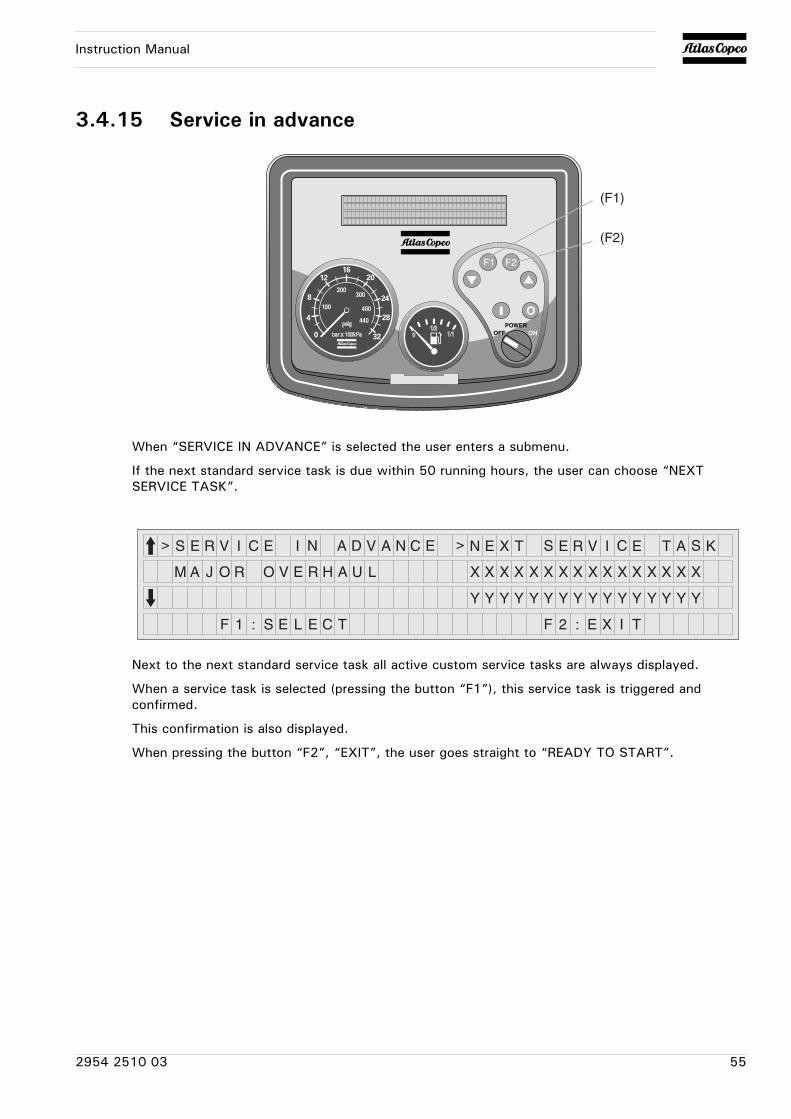
Instruction Manual
3.4.15 Service in advance
When “SERVICE IN ADVANCE” is selected the user enters a submenu.
If the next standard service task is due within 50 running hours, the user can choose “NEXT SERVICE TASK”.
Next to the next standard service task all active custom service tasks are always displayed.
When a service task is selected (pressing the button “F1”), this service task is triggered and confirmed.
This confirmation is also displayed.
When pressing the button “F2”, “EXIT”, the user goes straight to “READY TO START”.
(F1)
(F2)
2954 2510 03 55
Instruction Manual
4 Maintenance
4.1 Liability
The manufacturer does not accept any liability for any damage arising from the use of non-original parts and for modifications, additions or conversions made without the manufacturer’s approval in writing.
4.2 Service paks
A Service Pak is a collection of parts to be used for a specific maintenance task, e.g. after 50, after 500 and after 1000 running hours.
It guarantees that all necessary parts are replaced at the same time keeping down time to a minimum.
The order number of the Service Paks are listed in the Atlas Copco Parts List (ASL).
Use of service paks
Service Paks include all genuine parts needed for normal maintenance of both compressor and engine.
Service Paks minimize downtime and keep your maintenance budget low.
Order Service Paks at your local Atlas Copco dealer.
4.3 Service kits
A service kit is a collection of parts to fit a specific repair or rebuilding task.
It guarantees that all necessary parts are replaced at the same time which improves the uptime of the unit.
The order numbers of the Service Kits are listed in the Atlas Copco Parts List (ASL).
4.4 Storage
Run the compressor regularly, e.g. twice a week, until warm.
Load and unload the compressor a few times to operate the unloading and regulating components. Close the air outlet valves after stopping.
Contact Atlas Copco.
If the compressor is going to be stored without running from time to time, protective measures must be taken.
56 2954 2510 03
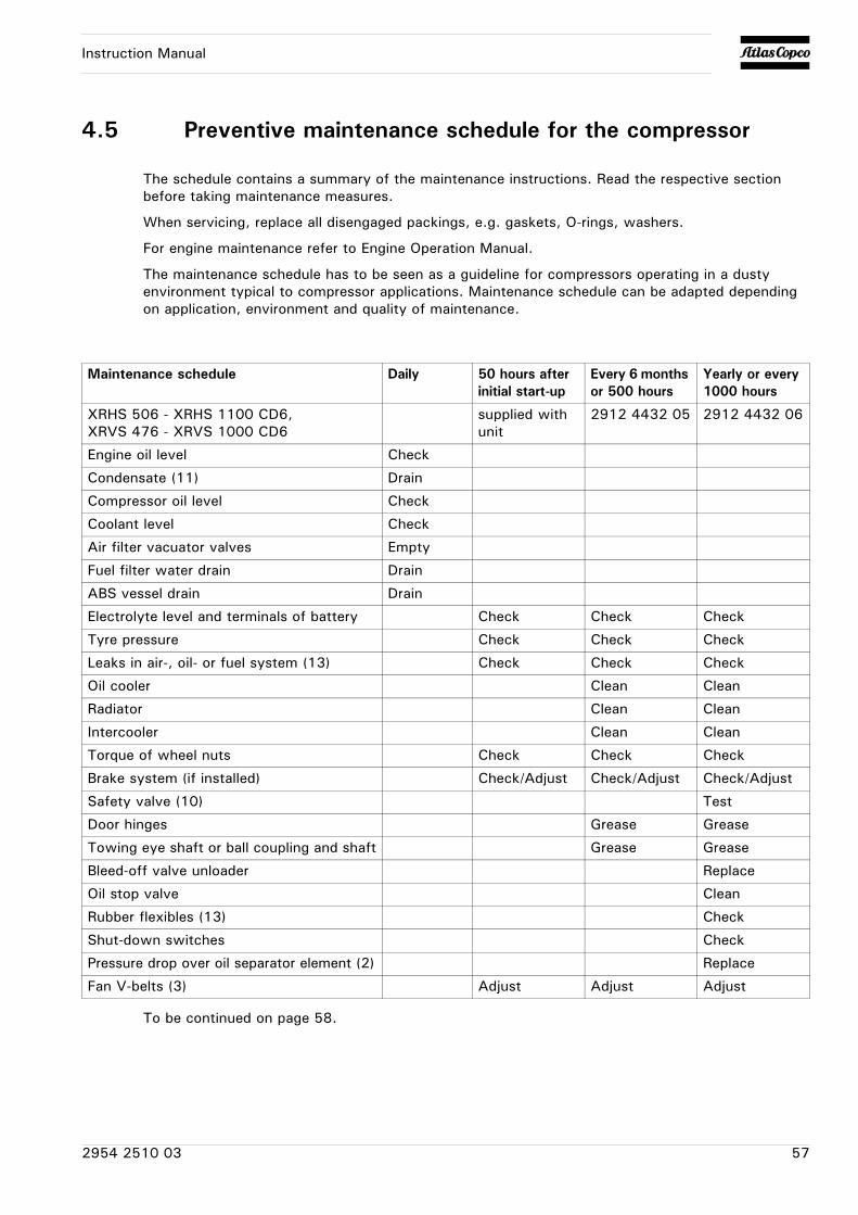
Instruction Manual
4.5 Preventive maintenance schedule for the compressor
The schedule contains a summary of the maintenance instructions. Read the respective section before taking maintenance measures.
When servicing, replace all disengaged packings, e.g. gaskets, O-rings, washers.
For engine maintenance refer to Engine Operation Manual.
The maintenance schedule has to be seen as a guideline for compressors operating in a dusty environment typical to compressor applications. Maintenance schedule can be adapted depending on application, environment and quality of maintenance.
To be continued on page 58.
Maintenance schedule Daily 50 hours after initial start-up
Every 6 months or 500 hours
Yearly or every 1000 hours
XRHS 506 - XRHS 1100 CD6, XRVS 476 - XRVS 1000 CD6
supplied with unit
2912 4432 05 2912 4432 06
Engine oil level Check
Condensate (11) Drain
Compressor oil level Check
Coolant level Check
Air filter vacuator valves Empty
Fuel filter water drain Drain
ABS vessel drain Drain
Electrolyte level and terminals of battery Check Check Check
Tyre pressure Check Check Check
Leaks in air-, oil- or fuel system (13) Check Check Check
Oil cooler Clean Clean
Radiator Clean Clean
Intercooler Clean Clean
Torque of wheel nuts Check Check Check
Brake system (if installed) Check/Adjust Check/Adjust Check/Adjust
Safety valve (10) Test
Door hinges Grease Grease
Towing eye shaft or ball coupling and shaft Grease Grease
Bleed-off valve unloader Replace
Oil stop valve Clean
Rubber flexibles (13) Check
Shut-down switches Check
Pressure drop over oil separator element (2) Replace
Fan V-belts (3) Adjust Adjust Adjust
2954 2510 03 57
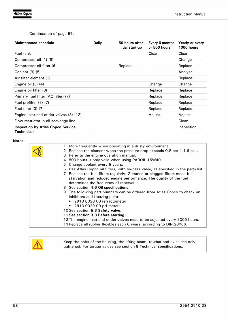
Instruction Manual
Continuation of page 57.
Notes
Maintenance schedule Daily 50 hours after initial start-up
Every 6 months or 500 hours
Yearly or every 1000 hours
Fuel tank Clean Clean
Compressor oil (1) (8) Change
Compressor oil filter (6) Replace Replace
Coolant (9) (5) Analyse
Air filter element (1) Replace
Engine oil (3) (4) Change Change
Engine oil filter (3) Replace Replace
Primary fuel filter (AC filter) (7) Replace Replace
Fuel prefilter (3) (7) Replace Replace
Fuel filter (3) (7) Replace Replace
Engine inlet and outlet valves (3) (12) Adjust Adjust
Flow restrictor in oil scavenge line Clean
Inspection by Atlas Copco Service Technician
Inspection
1 More frequently when operating in a dusty environment.2 Replace the element when the pressure drop exceeds 0.8 bar (11.6 psi).3 Refer to the engine operation manual.4 500 hours is only valid when using PAROIL 15W40.5 Change coolant every 5 years.6 Use Atlas Copco oil filters, with by-pass valve, as specified in the parts list.7 Replace the fuel filters regularly. Gummed or clogged filters mean fuel
starvation and reduced engine performance. The quality of the fuel determines the frequency of renewal.
8 See section 4.6 Oil specifications.9 The following part numbers can be ordered from Atlas Copco to check on
inhibitors and freezing point:• 2913 0028 00 refractometer• 2913 0029 00 pH meter.
10See section 5.3 Safety valve.11See section 3.3 Before starting.12The engine inlet and outlet valves need to be adjusted every 3000 hours.13Replace all rubber flexibles each 6 years, according to DIN 20066.
Keep the bolts of the housing, the lifting beam, towbar and axles securely tightened. For torque values see section 8 Technical specifications.
58 2954 2510 03
Instruction Manual
4.6 Oil specifications
High-quality, mineral, hydraulic or synthesized hydrocarbon oil with rust and oxidation inhibitors, anti-foam and anti-wear properties is recommended.The viscosity grade should correspond to the ambient temperature and ISO 3448, as follows:
4.6.1 Compressor oil
Synthetic compressor oil PAROIL S
Synthetic compressor oil PAROIL S68
It is strongly recommended to use Atlas Copco branded lubrication oils for both compressor and engine.
Only use synthetic compressor oil.
Type of lubricant Compressor Engine
between -25°C and -10°C PAROIL S
between -10°C and +30°C PAROIL S PAROIL 15W40
between +30°C and +50°C PAROIL S68 PAROIL 15W40
Never mix synthetic with mineral oil.
Remark:When changing from mineral to synthetic oil (or the other way around), you will need to do an extra rinse:
After doing the complete change procedure to synthetic oil, run the unit for a few minutes to allow good and complete circulation of the synthetic oil.Then drain the synthetic oil again and fill again with new synthetic oil. To set correct oil levels, proceed as in normal instruction.
Liter US gal Imp gal cu.ft Order number
can 5 1.3 1.1 0.175 1615 5950 01
can 20 5.3 4.4 0.7 1615 5951 01
barrel 210 55.2 46 7.35 1615 5952 01
container 1000 265 220 35 1604 7422 00
Liter US gal Imp gal cu.ft Order number
can 20 5.3 4.4 0.7 1604 7136 00
barrel 210 55.2 46 7.35 1604 7137 00
2954 2510 03 59
Instruction Manual
4.6.2 Engine oilPAROIL from Atlas Copco is the ONLY oil tested and approved for use in all engines built into Atlas Copco compressors and generators.Extensive laboratory and field endurance tests on Atlas Copco equipment have proven PAROIL to match all lubrication demands in varied conditions. It meets stringent quality control specifications to ensure your equipment will run smoothly and reliably.The quality lubricant additives in PAROIL allow for extended oil change intervals without any loss in performance or longevity.
PAROIL provides wear protection under extreme conditions. Powerful oxidation resistance, high chemical stability and rust- inhibiting additives help reduce corrosion, even within engines left idle for extended periods.
PAROIL contains high quality anti-oxidants to control deposits, sludge and contaminants that tend to build up under very high temperatures.PAROIL's detergent additives keep sludge forming particles in a fine suspension instead of allowing them to clog your filter and accumulate in the valve/rocker cover area.
PAROIL releases excess heat efficiently, whilst maintaining excellent bore-polish protection to limit oil consumption.PAROIL has an excellent Total Base Number (TBN) retention and more alkalinity to control acid formation.
PAROIL prevents Soot build-up
PAROIL is optimized for the latest low emission EURO -3 & -2, EPA TIER II & III engines running on low sulphur diesel for lower oil and fuel consumption.
PAROIL 5W30 is a Synthetic ultra high performance diesel engine oil with a high viscosity- index. Atlas Copco PAROIL 5W30 is designed to provide excellent lubrication from start-up in temperatures as low as -25°C (-13°F).
PAROIL 15W40 is a mineral based high performance diesel engine oil with a high viscosity- index. Atlas Copco PAROIL 15W40 is designed to provide a high level of performance and protection in 'standard' ambient conditions as from -15°C (5°F).
Synthetic engine oil PAROIL 5W30
Mineral engine oil PAROIL 15W40
Liter US gal Imp gal cu.ft Order number
can 5 1.3 1.1 0.175 1604 6060 00
can 20 5.3 4.4 0.7 1604 6059 00
Liter US gal Imp gal cu.ft Order number
can 5 1.3 1.1 0.175 1615 5953 00
can 20 5.3 4.4 0.7 1615 5954 00
barrel 210 55.2 46 7.35 1615 5955 00
60 2954 2510 03
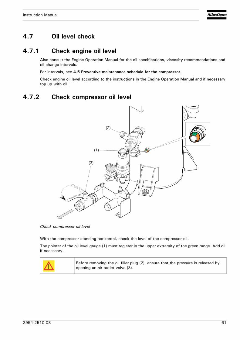
Instruction Manual
4.7 Oil level check
4.7.1 Check engine oil levelAlso consult the Engine Operation Manual for the oil specifications, viscosity recommendations and oil change intervals.
For intervals, see 4.5 Preventive maintenance schedule for the compressor.
Check engine oil level according to the instructions in the Engine Operation Manual and if necessary top up with oil.
4.7.2 Check compressor oil level
Check compressor oil level
With the compressor standing horizontal, check the level of the compressor oil.
The pointer of the oil level gauge (1) must register in the upper extremity of the green range. Add oil if necessary.
(1)
(2)
(3)
Before removing the oil filler plug (2), ensure that the pressure is released by opening an air outlet valve (3).
2954 2510 03 61
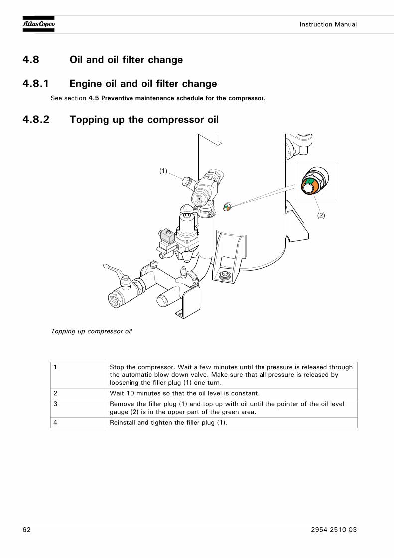
Instruction Manual
4.8 Oil and oil filter change
4.8.1 Engine oil and oil filter changeSee section 4.5 Preventive maintenance schedule for the compressor.
4.8.2 Topping up the compressor oil
Topping up compressor oil
(1)
(2)
1 Stop the compressor. Wait a few minutes until the pressure is released through the automatic blow-down valve. Make sure that all pressure is released by loosening the filler plug (1) one turn.
2 Wait 10 minutes so that the oil level is constant.
3 Remove the filler plug (1) and top up with oil until the pointer of the oil level gauge (2) is in the upper part of the green area.
4 Reinstall and tighten the filler plug (1).
62 2954 2510 03
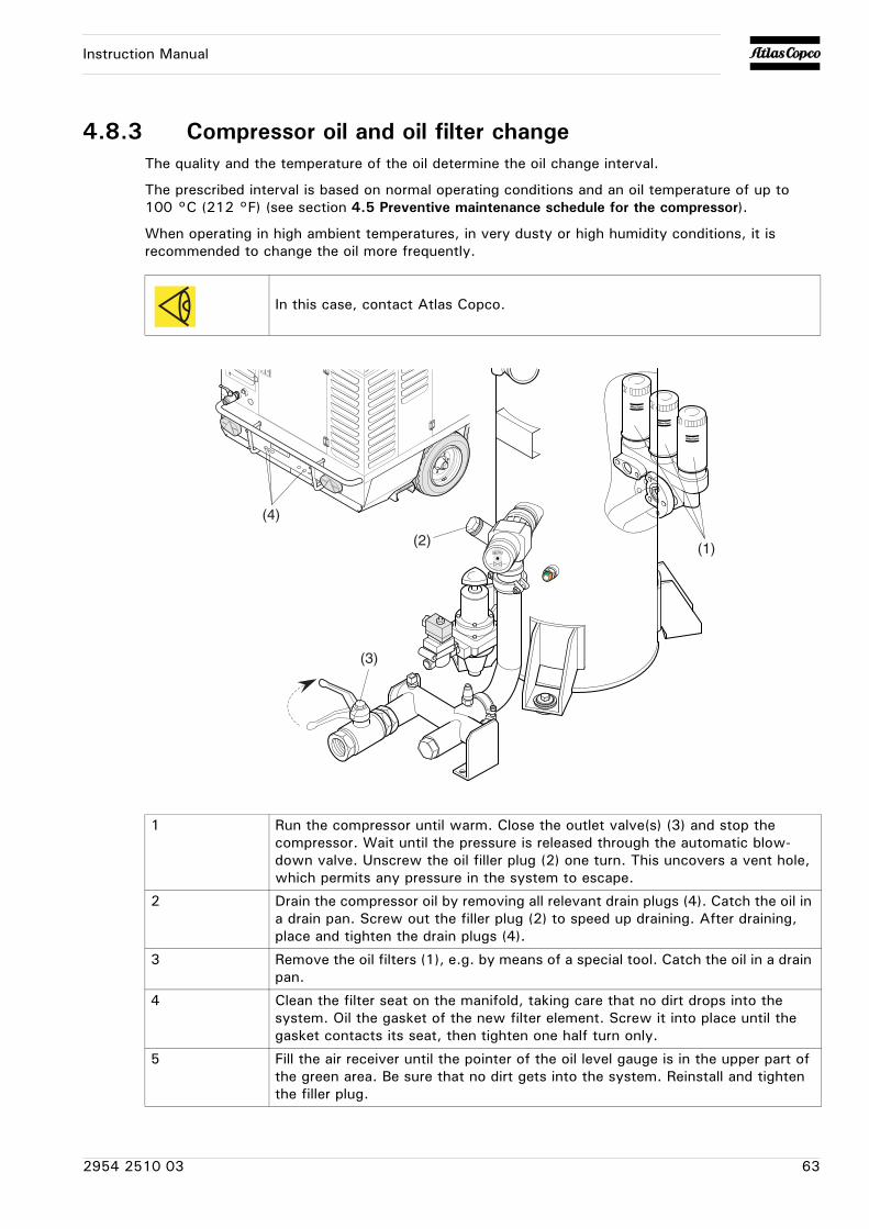
Instruction Manual
4.8.3 Compressor oil and oil filter changeThe quality and the temperature of the oil determine the oil change interval.
The prescribed interval is based on normal operating conditions and an oil temperature of up to 100 °C (212 °F) (see section 4.5 Preventive maintenance schedule for the compressor).
When operating in high ambient temperatures, in very dusty or high humidity conditions, it is recommended to change the oil more frequently.
In this case, contact Atlas Copco.
1 Run the compressor until warm. Close the outlet valve(s) (3) and stop the compressor. Wait until the pressure is released through the automatic blow-down valve. Unscrew the oil filler plug (2) one turn. This uncovers a vent hole, which permits any pressure in the system to escape.
2 Drain the compressor oil by removing all relevant drain plugs (4). Catch the oil in a drain pan. Screw out the filler plug (2) to speed up draining. After draining, place and tighten the drain plugs (4).
3 Remove the oil filters (1), e.g. by means of a special tool. Catch the oil in a drain pan.
4 Clean the filter seat on the manifold, taking care that no dirt drops into the system. Oil the gasket of the new filter element. Screw it into place until the gasket contacts its seat, then tighten one half turn only.
5 Fill the air receiver until the pointer of the oil level gauge is in the upper part of the green area. Be sure that no dirt gets into the system. Reinstall and tighten the filler plug.
(1)(2)
(3)
(4)
2954 2510 03 63
Instruction Manual
6 Start the compressor and let it run unloaded for a few minutes.
7 Stop the compressor, wait a few minutes and top up with oil until the pointer of the oil level gauge is in the upper part of the green area.
Never add more oil. Overfilling results in oil consumption.
64 2954 2510 03
Instruction Manual
4.9 Coolant specifications
The use of the correct coolant is important for good heat transfer and protection of liquid-cooled engines. Coolants used in these engines must be mixtures of good quality water (distilled or de-ionised), special coolant additives and if necessary freeze protection. Coolant that is not to manufacturer's specification will result in mechanical damage of the engine.
The freezing point of the coolant must be lower than the freezing point that can occur in the area. The difference must be at least 5 °C (9 °F). If the coolant freezes, it may crack the cylinder block, radiator or coolant pump.
Consult the engine's operation manual and follow the manufacturer's directions.
Never remove the cooling system filler cap while coolant is hot.The system may be under pressure. Remove the cap slowly and only when coolant is at ambient temperature. A sudden release of pressure from a heated cooling system can result in personal injury from the splash of hot coolant.
It is strongly recommended to use Atlas Copco branded coolant.
Never mix different coolants and mix the coolant components outside the cooling system.
2954 2510 03 65

Instruction Manual
4.9.1 PARCOOL EGPARCOOL EG is the only coolant that has been tested and approved by all engine manufacturers currently in use in Atlas Copco compressors and generators.
Atlas Copco's PARCOOL EG extended life coolant is the new range of organic coolants purpose designed to meet the needs of modern engines. PARCOOL EG can help prevent leaks caused by corrosion. PARCOOL EG is also fully compatible with all sealants and gasket types developed to join different materials used within an engine.
PARCOOL EG is a ready to use Ethylene Glycol based coolant, premixed in an optimum 50/50 dilution ratio, for antifreeze protection guaranteed to -40°C (-40°F).
Because PARCOOL EG inhibits corrosion, deposit formation is minimized. This effectively eliminates the problem of restricted flow through the engine coolant ducts and the radiator, minimizing the risk for engine overheating and possible failure.
It reduces water pump seal wear and has excellent stability when subjected to sustained high operating temperatures.
PARCOOL EG is free of nitride and amines to protect your health and the environment. Longer service life reduces the amount of coolant produced and needing disposal to minimise environmental impact.
PARCOOL EG
To ensure protection against corrosion, cavitation and formation of deposits, the concentration of the additives in the coolant must be kept between certain limits, as stated by the manufacturer's guidelines. Topping up the coolant with water only, changes the concentration and is therefore not allowed.
Liquid-cooled engines are factory-filled with this type of coolant mixture.
PARCOOL EG Concentrate
Liter US gal Imp gal cu.ft Order number
can 5 1.3 1.1 0.175 1604 5308 00
can 20 5.3 4.4 0.7 1604 5307 01
barrel 210 55.2 46 7.35 1604 5306 00
Liter US gal Imp gal cu.ft Order number
can 5 1.3 1.1 0.175 1604 8159 00
66 2954 2510 03

Instruction Manual
4.9.2 Handling PARCOOL EGPARCOOL EG should be stored at ambient temperatures, while periods of exposure to temperatures above 35° should be minimized. PARCOOL EG can be stored for a minimum of 5 years in unopened containers without any effect on the product quality of performance.
PARCOOL EG is compatible with most other coolants based on ethylene glycol, but you only get the benefits of 5 years protection when its used on its own. Exclusive use of PARCOOL EG is recommended for optimum corrosion protection and sludge control.
For simple density-measuring of Ethylene Glycol and Propylene Glycol in general the standard available ‘density’ measuring devices are used to measure the concentration of EG. In case a device is used to measure EG, no PG can be measured afterwards as a result of the difference in the density. More specific measurements can be done by the use of a refractometer. This device can measure both EG and PG. A mix of both products will be show unreliable results!
Mixed EG coolants with identical glycol type can be measured by use of a refractometer as well as the ‘density’ system. The mixed coolants will be considered as one product.
The use of distilled water is recommended. If you have exceptionally soft water it would be acceptable, as well. Basically, the engine metals are going to corrode to some extent no matter what water you use, and hard water will encourage the resulting metal salts to precipitate.
PARCOOL EG comes as a pre-mixed coolant to safeguard the quality of the complete product.
It is recommended that topping up of the cooling system is always done with PARCOOL EG.
2954 2510 03 67
Instruction Manual
4.10 Coolant check
In order to guarantee the lifetime and quality of the product, thus to optimise engine protection, regular coolant-condition-analysis is advisable.
The quality of the product can be determined by three parameters:
Visual check
• Verify the outlook of the coolant regarding colour and make sure that no loose particles are floating around.
pH measurement
• Check the pH value of the coolant using a pH-measuring device.
• The pH-meter can be ordered from Atlas Copco with part number 2913 0029 00.
• Typical value for EG = 8.6.
• If the pH-level is below 7 or above 9.5, the coolant should be replaced.
Glycol concentration measurement
• To optimise the unique engine protection features of the PARCOOL EG the concentration of the Glycol in the water should be always above 33 vol.%.
• Mixtures with more than 68 vol.% mix ratio in water are not recommended, as this will lead to high engine operating temperatures.
• A refractometer can be ordered from Atlas Copco with part number 2913 0028 00.
Never remove the cooling system filler cap while coolant is hot.
The system may be under pressure. Remove the cap slowly and only when coolant is at ambient temperature. A sudden release of pressure from a heated cooling system can result in personal injury from the splash of hot coolant.
In case of a mix of different coolant products this type of measurement might provide incorrect values.
68 2954 2510 03
Instruction Manual
4.11 Topping up/replacing coolant
• Verify if the engine cooling system is in a good condition (no leaks, clean,...).
• Check the condition of the coolant.
• If the condition of the coolant is outside the limits, the complete coolant should be replaced (see section 4.11.3 Replacing the coolant).
• Always top-up with PARCOOL EG Concentrate / PARCOOL EG.
• Topping up the coolant with water only, changes the concentration of additives and is therefore not allowed.
2954 2510 03 69
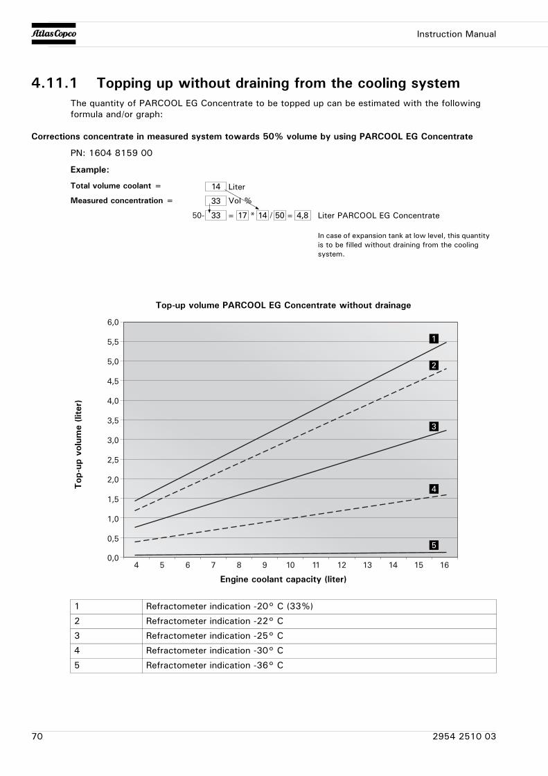
Instruction Manual
4.11.1 Topping up without draining from the cooling systemThe quantity of PARCOOL EG Concentrate to be topped up can be estimated with the following formula and/or graph:
Corrections concentrate in measured system towards 50% volume by using PARCOOL EG Concentrate
PN: 1604 8159 00
Example:
1 Refractometer indication -20° C (33%)
2 Refractometer indication -22° C
3 Refractometer indication -25° C
4 Refractometer indication -30° C
5 Refractometer indication -36° C
14
33
33 17 14 50 4,850- = =* /
Total volume coolant =
Measured concentration =
In case of expansion tank at low level, this quantity is to be filled without draining from the cooling system.
Liter
Vol %
Liter PARCOOL EG Concentrate
40,0
0,5
1,0
1,5
2,0
2,5
3,0
3,5
4,0
4,5
5,0
5,5
6,0
5 6 7 8 9 10 11 12 13 14 15 16
1
2
3
4
5
Top-up volume PARCOOL EG Concentrate without drainage
Engine coolant capacity (liter)
Top
-up
volu
me
(lite
r)
70 2954 2510 03
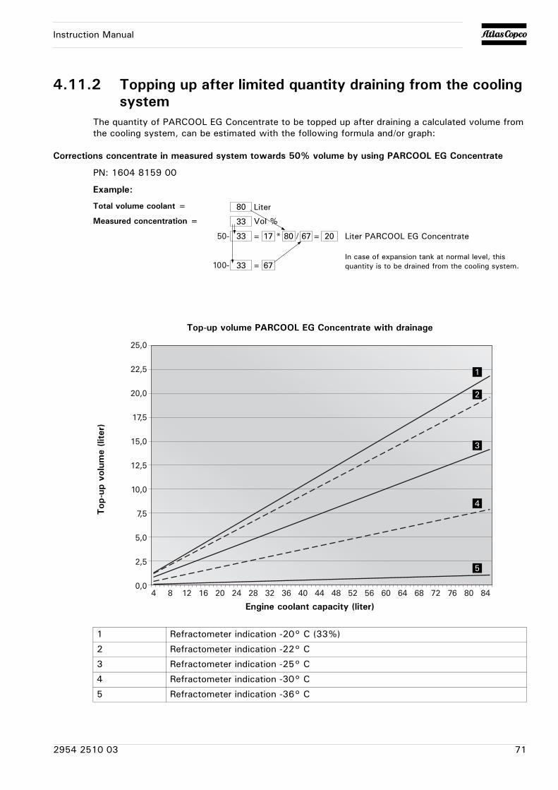
Instruction Manual
4.11.2 Topping up after limited quantity draining from the cooling system
The quantity of PARCOOL EG Concentrate to be topped up after draining a calculated volume from the cooling system, can be estimated with the following formula and/or graph:
Corrections concentrate in measured system towards 50% volume by using PARCOOL EG Concentrate
PN: 1604 8159 00
Example:
1 Refractometer indication -20° C (33%)
2 Refractometer indication -22° C
3 Refractometer indication -25° C
4 Refractometer indication -30° C
5 Refractometer indication -36° C
80
33
33
33
17
67
80 67 2050-
100-
= =* /
=
Total volume coolant =
Measured concentration =
In case of expansion tank at normal level, this quantity is to be drained from the cooling system.
Liter
Vol %
Liter PARCOOL EG Concentrate
4 8 12 16 20 24 28 32 36 40 44 48 52 56 60 64 68 72 76 80 840,0
2,5
5,0
7,5
10,0
12,5
15,0
17,5
20,0
22,5
25,0
1
2
3
4
5
Top-up volume PARCOOL EG Concentrate with drainage
Engine coolant capacity (liter)
Top
-up
volu
me
(lite
r)
2954 2510 03 71
Instruction Manual
4.11.3 Replacing the coolant
Drain
• Completely drain the entire cooling system.
• Used coolant must be disposed or recycled in accordance with laws and local regulations.
Flush
• Flush twice with clean water. Used coolant must be disposed or recycled in accordance with laws and local regulations.
• From the Atlas Copco Instruction book, determine the amount of PARCOOL EG required and pour into the radiator top tank.
• It should be clearly understood that the risk for contamination is reduced in case of proper cleaning.
• In case a certain content of ‘other’ coolant remains in the system, the coolant with the lowest properties influences the quality of the ‘mixed’ coolant.
Fill
• To assure proper operation and the release of trapped air, run the engine until normal engine operation temperature is reached. Turn off the engine and allow to cool.
• Recheck coolant level and add if necessary.
Caution: do not top off when the engine is hot.
72 2954 2510 03
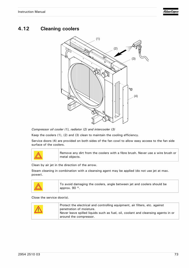
Instruction Manual
4.12 Cleaning coolers
Compressor oil cooler (1), radiator (2) and intercooler (3)
Keep the coolers (1), (2) and (3) clean to maintain the cooling efficiency.
Service doors (4) are provided on both sides of the fan cowl to allow easy access to the fan side surface of the coolers.
Clean by air jet in the direction of the arrow.
Steam cleaning in combination with a cleansing agent may be applied (do not use jet at max. power).
Close the service door(s).
(1)
(2)
(3)
(4)
Remove any dirt from the coolers with a fibre brush. Never use a wire brush or metal objects.
To avoid damaging the coolers, angle between jet and coolers should be approx. 90 °.
Protect the electrical and controlling equipment, air filters, etc. against penetration of moisture.Never leave spilled liquids such as fuel, oil, coolant and cleansing agents in or around the compressor.
2954 2510 03 73
Instruction Manual
4.13 Battery care
If the battery is still dry, it must be activated as described in section 4.13.2 Activating a dry-charged battery.
The battery must be in operation within 2 months from being activated; if not, it needs to be recharged first.
4.13.1 Electrolyte
Electrolyte in batteries is a sulphuric acid solution in distilled water.
The solution must be made up before being introduced into the battery.
4.13.2 Activating a dry-charged battery
• Take out the battery.
• Battery and electrolyte must be at equal temperature above 10 °C (50 °F).
• Remove cover and/or plug from each cell.
• Fill each cell with electrolyte until the level reaches the mark on the battery. If there is no mark on the battery, the level must be above the plates for at least 10 mm (0.4 in) to 15 mm (0.6 in).
• Rock the battery a few times so that possible air bubbles can escape; wait 10 minutes and check the level in each cell once more; if required, add electrolyte.
• Refit plugs and/or cover.
• Place the battery in the compressor.
Before handling batteries, read the relevant safety precautions and act accordingly.
Read the safety instructions carefully.
Always pour the sulphuric acid carefully into the distilled water; never pour the water into the acid.
74 2954 2510 03
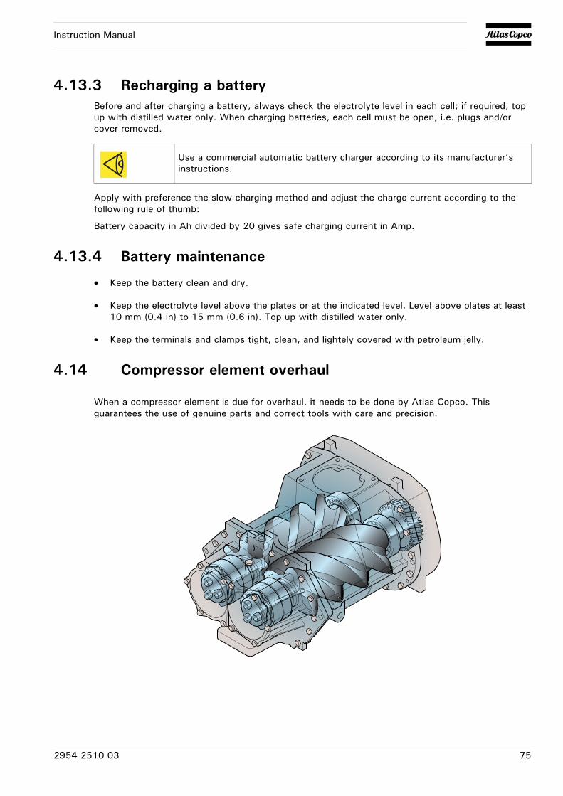
Instruction Manual
4.13.3 Recharging a batteryBefore and after charging a battery, always check the electrolyte level in each cell; if required, top up with distilled water only. When charging batteries, each cell must be open, i.e. plugs and/or cover removed.
Apply with preference the slow charging method and adjust the charge current according to the following rule of thumb:
Battery capacity in Ah divided by 20 gives safe charging current in Amp.
4.13.4 Battery maintenance
• Keep the battery clean and dry.
• Keep the electrolyte level above the plates or at the indicated level. Level above plates at least 10 mm (0.4 in) to 15 mm (0.6 in). Top up with distilled water only.
• Keep the terminals and clamps tight, clean, and lightely covered with petroleum jelly.
4.14 Compressor element overhaul
When a compressor element is due for overhaul, it needs to be done by Atlas Copco. This guarantees the use of genuine parts and correct tools with care and precision.
Use a commercial automatic battery charger according to its manufacturer’s instructions.
2954 2510 03 75
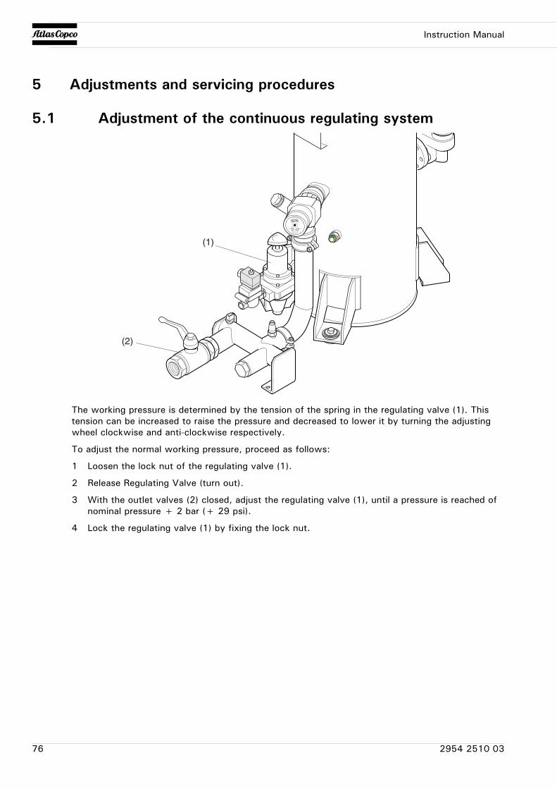
Instruction Manual
5 Adjustments and servicing procedures
5.1 Adjustment of the continuous regulating system
The working pressure is determined by the tension of the spring in the regulating valve (1). This tension can be increased to raise the pressure and decreased to lower it by turning the adjusting wheel clockwise and anti-clockwise respectively.
To adjust the normal working pressure, proceed as follows:
1 Loosen the lock nut of the regulating valve (1).
2 Release Regulating Valve (turn out).
3 With the outlet valves (2) closed, adjust the regulating valve (1), until a pressure is reached of nominal pressure + 2 bar (+ 29 psi).
4 Lock the regulating valve (1) by fixing the lock nut.
(1)
(2)
76 2954 2510 03
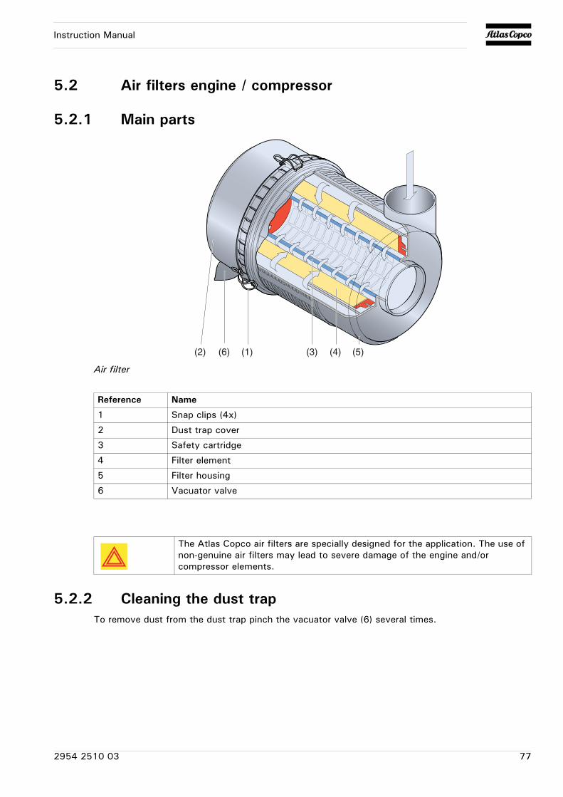
Instruction Manual
5.2 Air filters engine / compressor
5.2.1 Main parts
Air filter
5.2.2 Cleaning the dust trapTo remove dust from the dust trap pinch the vacuator valve (6) several times.
(6) (1)(2) (3) (4) (5)
Reference Name
1 Snap clips (4x)
2 Dust trap cover
3 Safety cartridge
4 Filter element
5 Filter housing
6 Vacuator valve
The Atlas Copco air filters are specially designed for the application. The use of non-genuine air filters may lead to severe damage of the engine and/or compressor elements.
2954 2510 03 77
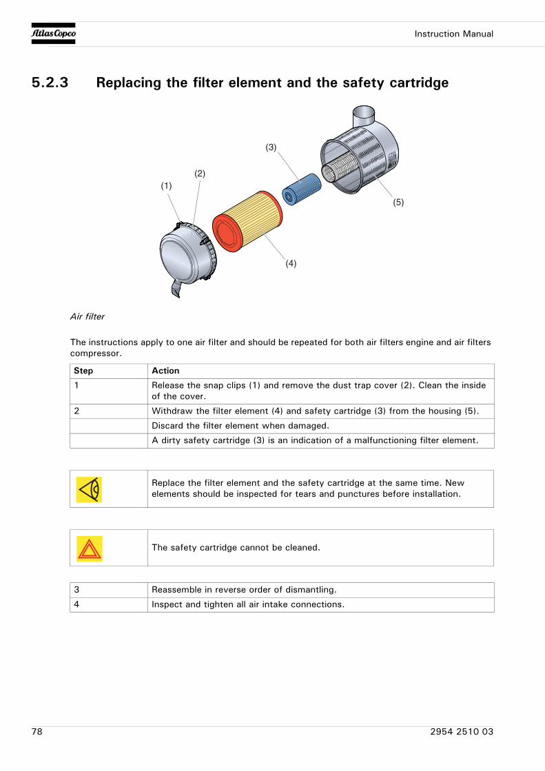
Instruction Manual
5.2.3 Replacing the filter element and the safety cartridge
Air filter
The instructions apply to one air filter and should be repeated for both air filters engine and air filters compressor.
(1)(2)
(3)
(4)
(5)
Step Action
1 Release the snap clips (1) and remove the dust trap cover (2). Clean the inside of the cover.
2 Withdraw the filter element (4) and safety cartridge (3) from the housing (5).
Discard the filter element when damaged.
A dirty safety cartridge (3) is an indication of a malfunctioning filter element.
Replace the filter element and the safety cartridge at the same time. New elements should be inspected for tears and punctures before installation.
The safety cartridge cannot be cleaned.
3 Reassemble in reverse order of dismantling.
4 Inspect and tighten all air intake connections.
78 2954 2510 03
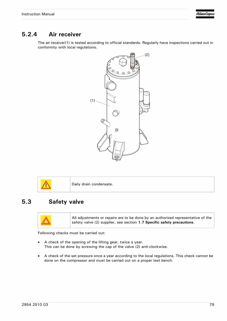
Instruction Manual
5.2.4 Air receiverThe air receiver(1) is tested according to official standards. Regularly have inspections carried out in conformity with local regulations.
5.3 Safety valve
Following checks must be carried out:
• A check of the opening of the lifting gear, twice a year.This can be done by screwing the cap of the valve (2) anti-clockwise.
• A check of the set pressure once a year according to the local regulations. This check cannot be done on the compressor and must be carried out on a proper test bench.
Daily drain condensate.
(1)
(2)
All adjustments or repairs are to be done by an authorized representative of the safety valve (2) supplier, see section 1.7 Specific safety precautions.
2954 2510 03 79
Instruction Manual
5.4 Fuel system
5.4.1 Priming instructions
Prime the fuel system in order to fill the fuel filter. Prime the fuel system in order to purge trapped air (see paragraph 3.4.4 Specific start procedure). The fuel system should be primed under the following conditions:
• Compressor is put in operation for the first time
• Running out of fuel
• Storage
• Replacement of the fuel filter
Fuel leaked or spilled onto hot surfaces or electrical components can cause a fire. To help prevent possible injury, turn the “ON/OFF” switch in position “OFF” when changing fuel filters or water separator elements. Clean up fuel spills immediately.
Do not loosen the fuel lines at the fuel manifold. The fittings may be damaged and/or a loss of priming pressure may occur when the fuel lines are loosened.
80 2954 2510 03
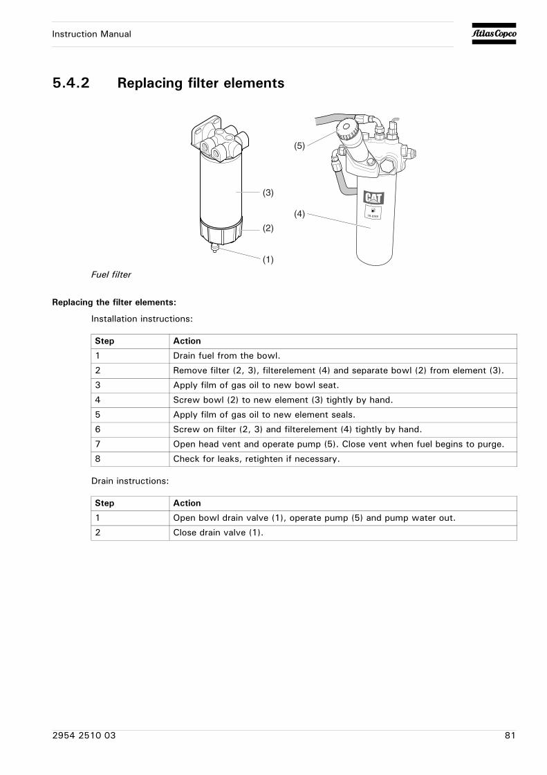
Instruction Manual
5.4.2 Replacing filter elements
Fuel filter
Replacing the filter elements:
Installation instructions:
Drain instructions:
(5)
(4)
(1)
(2)
(3)
Step Action
1 Drain fuel from the bowl.
2 Remove filter (2, 3), filterelement (4) and separate bowl (2) from element (3).
3 Apply film of gas oil to new bowl seat.
4 Screw bowl (2) to new element (3) tightly by hand.
5 Apply film of gas oil to new element seals.
6 Screw on filter (2, 3) and filterelement (4) tightly by hand.
7 Open head vent and operate pump (5). Close vent when fuel begins to purge.
8 Check for leaks, retighten if necessary.
Step Action
1 Open bowl drain valve (1), operate pump (5) and pump water out.
2 Close drain valve (1).
2954 2510 03 81
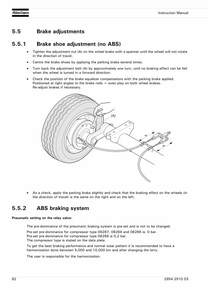
Instruction Manual
5.5 Brake adjustments
5.5.1 Brake shoe adjustment (no ABS)• Tighten the adjustment nut (A) on the wheel brake with a spanner until the wheel will not rotate
in the direction of travel.
• Centre the brake shoes by applying the parking brake several times.
• Turn back the adjustment bolt (A) by approximately one turn, until no braking effect can be felt when the wheel is turned in a forward direction.
• Check the position of the brake equalizer compensators with the parking brake applied.Positioned at right angles to the brake rods = even play on both wheel brakes.Re-adjust brakes if necessary.
• As a check, apply the parking brake slightly and check that the braking effect on the wheels (in the direction of travel) is the same on the right and on the left.
5.5.2 ABS braking system
Pneumatic setting on the relay valve:
The pre-dominance of the pneumatic braking system is pre-set and is not to be changed.
Pre-set pre-dominance for compressor type 06287, 06264 and 06266 is: 0 bar.Pre-set pre-dominance for compressor type 06288 is 0,2 bar.The compressor type is stated on the data plate.
To get the best braking performance and normal wear pattern it is recommended to have a harmonization done between 5,000 and 10,000 km and after changing the lorry.
The user is responsible for the harmonization.
(A)
82 2954 2510 03
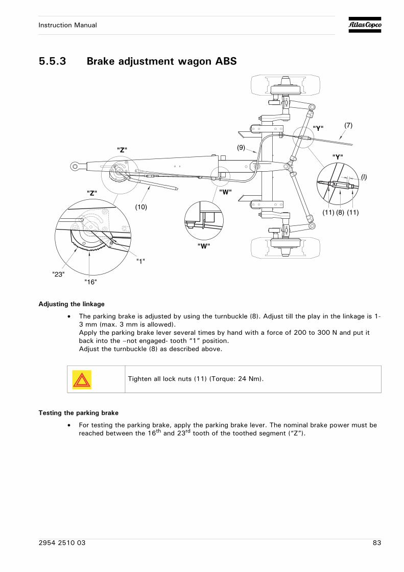
Instruction Manual
5.5.3 Brake adjustment wagon ABS
Adjusting the linkage
• The parking brake is adjusted by using the turnbuckle (8). Adjust till the play in the linkage is 1-3 mm (max. 3 mm is allowed).Apply the parking brake lever several times by hand with a force of 200 to 300 N and put it back into the –not engaged- tooth “1” position.Adjust the turnbuckle (8) as described above.
Testing the parking brake
• For testing the parking brake, apply the parking brake lever. The nominal brake power must be reached between the 16th and 23rd tooth of the toothed segment (“Z”).
"W"
"Y"
(8)(11) (11)
(l)
"1"
"Z"
"16""23"
(10)
"Z"
"W"
(9)
(7)"Y"
Tighten all lock nuts (11) (Torque: 24 Nm).
2954 2510 03 83
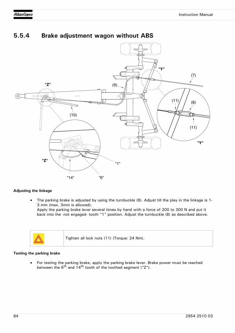
Instruction Manual
5.5.4 Brake adjustment wagon without ABS
Adjusting the linkage
• The parking brake is adjusted by using the turnbuckle (8). Adjust till the play in the linkage is 1-3 mm (max. 3mm is allowed).Apply the parking brake lever several times by hand with a force of 200 to 300 N and put it back into the -not engaged- tooth “1” position. Adjust the turnbuckle (8) as described above.
Testing the parking brake
• For testing the parking brake, apply the parking brake lever. Brake power must be reached between the 6th and 14th tooth of the toothed segment (“Z”).
(10)
"Z" (9)
(7)
"Y"
"Y"
(11)
(11) (8)
"Z"
"14" "6"
"1"
Tighten all lock nuts (11) (Torque: 24 Nm).
84 2954 2510 03
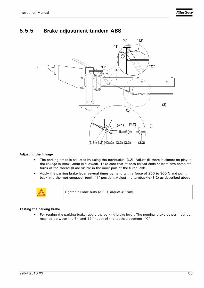
Instruction Manual
5.5.5 Brake adjustment tandem ABS
Adjusting the linkage
• The parking brake is adjusted by using the turnbuckle (3.2). Adjust till there is almost no play in the linkage is (max. 3mm is allowed). Take care that at both thread ends at least two complete turns of the thread (l) are visible in the inner part of the turnbuckle.
• Apply the parking brake lever several times by hand with a force of 200 to 300 N and put it back into the -not engaged- tooth “1” position. Adjust the turnbuckle (3.2) as described above.
Testing the parking brake
• For testing the parking brake, apply the parking brake lever. The nominal brake power must be reached between the 6th and 12th tooth of the toothed segment (“C”).
"C"
(3)
(4)
"1"
"12""6"
"C"
(3.3)
(4.1)
(4.2)
(3.2) (l)
(3.3)(3.3) (3.3)(42±2)
Tighten all lock nuts (3.3) (Torque: 40 Nm).
2954 2510 03 85
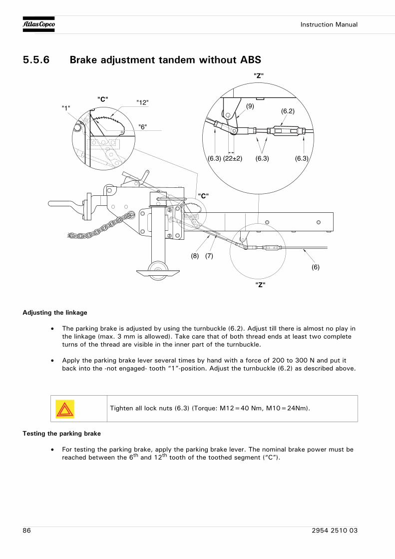
Instruction Manual
5.5.6 Brake adjustment tandem without ABS
Adjusting the linkage
• The parking brake is adjusted by using the turnbuckle (6.2). Adjust till there is almost no play in the linkage (max. 3 mm is allowed). Take care that of both thread ends at least two complete turns of the thread are visible in the inner part of the turnbuckle.
• Apply the parking brake lever several times by hand with a force of 200 to 300 N and put it back into the -not engaged- tooth “1”-position. Adjust the turnbuckle (6.2) as described above.
Testing the parking brake
• For testing the parking brake, apply the parking brake lever. The nominal brake power must be reached between the 6th and 12th tooth of the toothed segment (“C”).
"C""1"
"6"
"12"
"Z"
(6.3)(6.3)(6.3) (22±2)
(9)(6.2)
(8)
"Z"
"C"
(7)
(6)
Tighten all lock nuts (6.3) (Torque: M12=40 Nm, M10=24Nm).
86 2954 2510 03
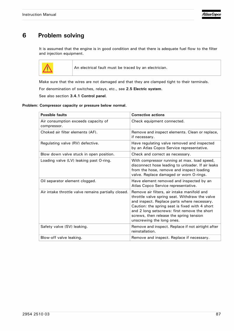
Instruction Manual
6 Problem solving
It is assumed that the engine is in good condition and that there is adequate fuel flow to the filter and injection equipment.
Make sure that the wires are not damaged and that they are clamped tight to their terminals.
For denomination of switches, relays, etc., see 2.5 Electric system.
See also section 3.4.1 Control panel.
Problem: Compressor capacity or pressure below normal.
An electrical fault must be traced by an electrician.
Possible faults Corrective actions
Air consumption exceeds capacity of compressor.
Check equipment connected.
Choked air filter elements (AF). Remove and inspect elements. Clean or replace, if necessary.
Regulating valve (RV) defective. Have regulating valve removed and inspected by an Atlas Copco Service representative.
Blow down valve stuck in open position. Check and correct as necessary.
Loading valve (LV) leaking past O-ring. With compressor running at max. load speed, disconnect hose leading to unloader. If air leaks from the hose, remove and inspect loading valve. Replace damaged or worn O-rings.
Oil separator element clogged. Have element removed and inspected by an Atlas Copco Service representative.
Air intake throttle valve remains partially closed. Remove air filters, air intake manifold and throttle valve spring seat. Withdraw the valve and inspect. Replace parts where necessary. Caution: the spring seat is fixed with 4 short and 2 long setscrews: first remove the short screws, then release the spring tension unscrewing the long ones.
Safety valve (SV) leaking. Remove and inspect. Replace if not airtight after reinstallation.
Blow-off valve leaking. Remove and inspect. Replace if necessary.
2954 2510 03 87
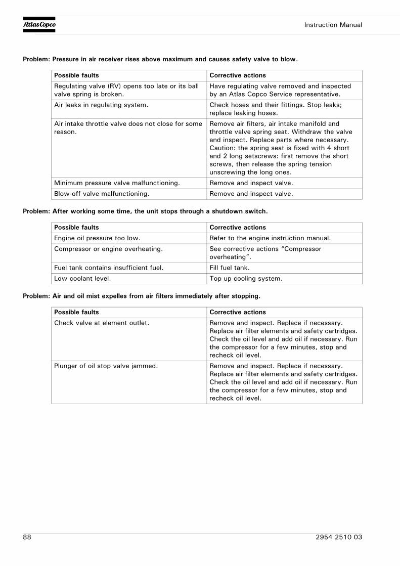
Instruction Manual
Problem: Pressure in air receiver rises above maximum and causes safety valve to blow.
Problem: After working some time, the unit stops through a shutdown switch.
Problem: Air and oil mist expelles from air filters immediately after stopping.
Possible faults Corrective actions
Regulating valve (RV) opens too late or its ball valve spring is broken.
Have regulating valve removed and inspected by an Atlas Copco Service representative.
Air leaks in regulating system. Check hoses and their fittings. Stop leaks; replace leaking hoses.
Air intake throttle valve does not close for some reason.
Remove air filters, air intake manifold and throttle valve spring seat. Withdraw the valve and inspect. Replace parts where necessary. Caution: the spring seat is fixed with 4 short and 2 long setscrews: first remove the short screws, then release the spring tension unscrewing the long ones.
Minimum pressure valve malfunctioning. Remove and inspect valve.
Blow-off valve malfunctioning. Remove and inspect valve.
Possible faults Corrective actions
Engine oil pressure too low. Refer to the engine instruction manual.
Compressor or engine overheating. See corrective actions “Compressor overheating”.
Fuel tank contains insufficient fuel. Fill fuel tank.
Low coolant level. Top up cooling system.
Possible faults Corrective actions
Check valve at element outlet. Remove and inspect. Replace if necessary. Replace air filter elements and safety cartridges. Check the oil level and add oil if necessary. Run the compressor for a few minutes, stop and recheck oil level.
Plunger of oil stop valve jammed. Remove and inspect. Replace if necessary. Replace air filter elements and safety cartridges. Check the oil level and add oil if necessary. Run the compressor for a few minutes, stop and recheck oil level.
88 2954 2510 03
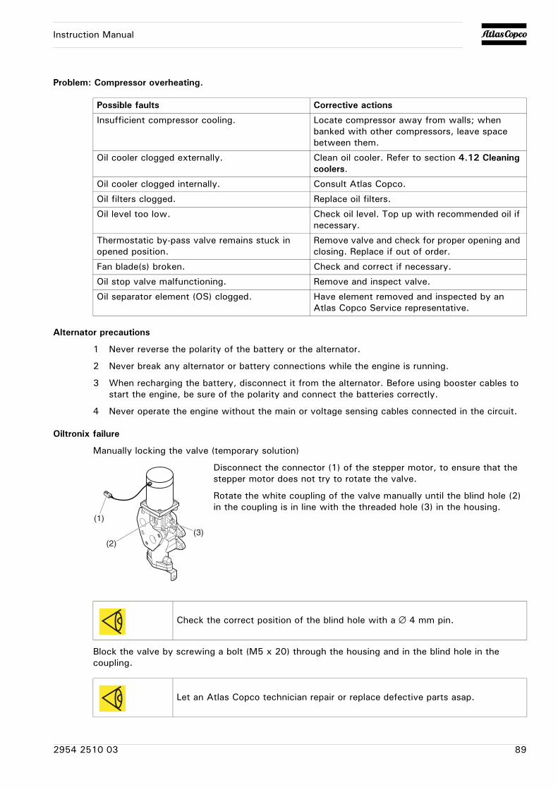
Instruction Manual
Problem: Compressor overheating.
Alternator precautions
1 Never reverse the polarity of the battery or the alternator.
2 Never break any alternator or battery connections while the engine is running.
3 When recharging the battery, disconnect it from the alternator. Before using booster cables to start the engine, be sure of the polarity and connect the batteries correctly.
4 Never operate the engine without the main or voltage sensing cables connected in the circuit.
Oiltronix failure
Manually locking the valve (temporary solution)
Disconnect the connector (1) of the stepper motor, to ensure that the stepper motor does not try to rotate the valve.
Rotate the white coupling of the valve manually until the blind hole (2) in the coupling is in line with the threaded hole (3) in the housing.
Block the valve by screwing a bolt (M5 x 20) through the housing and in the blind hole in the coupling.
Possible faults Corrective actions
Insufficient compressor cooling. Locate compressor away from walls; when banked with other compressors, leave space between them.
Oil cooler clogged externally. Clean oil cooler. Refer to section 4.12 Cleaning coolers.
Oil cooler clogged internally. Consult Atlas Copco.
Oil filters clogged. Replace oil filters.
Oil level too low. Check oil level. Top up with recommended oil if necessary.
Thermostatic by-pass valve remains stuck in opened position.
Remove valve and check for proper opening and closing. Replace if out of order.
Fan blade(s) broken. Check and correct if necessary.
Oil stop valve malfunctioning. Remove and inspect valve.
Oil separator element (OS) clogged. Have element removed and inspected by an Atlas Copco Service representative.
Check the correct position of the blind hole with a ∅ 4 mm pin.
Let an Atlas Copco technician repair or replace defective parts asap.
(1)
(2)(3)
2954 2510 03 89
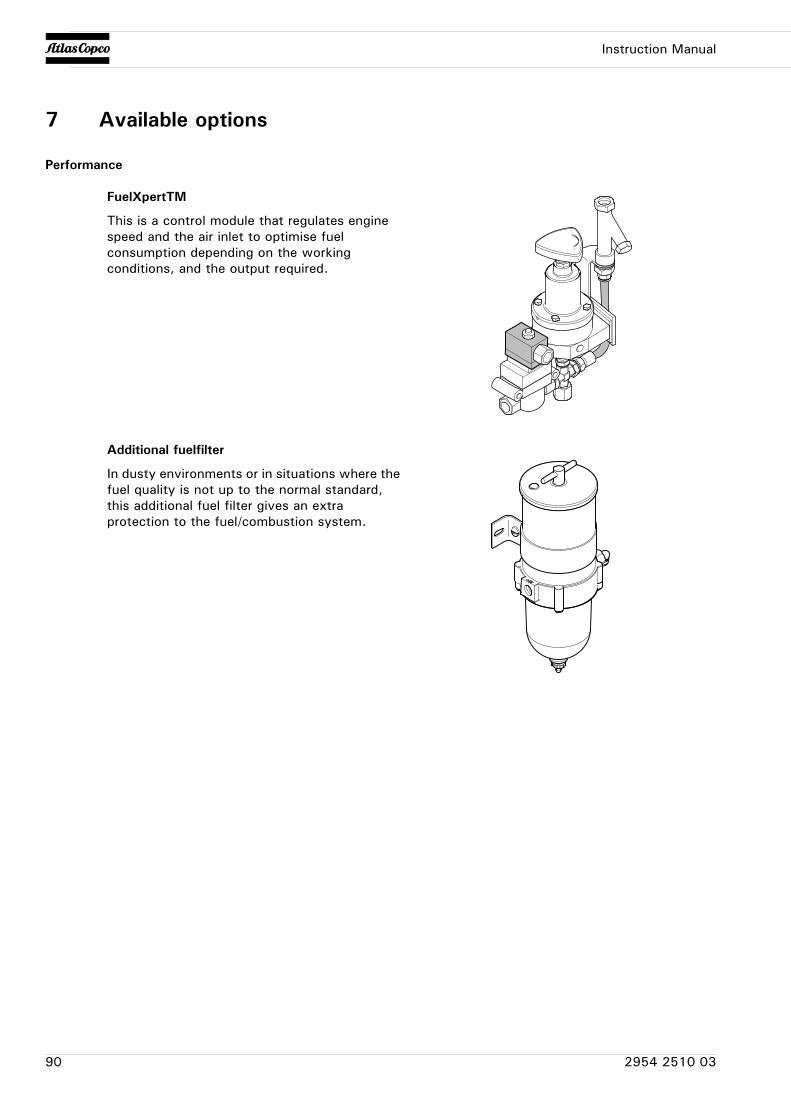
Instruction Manual
7 Available options
Performance
FuelXpertTM
This is a control module that regulates engine speed and the air inlet to optimise fuel consumption depending on the working conditions, and the output required.
Additional fuelfilter
In dusty environments or in situations where the fuel quality is not up to the normal standard, this additional fuel filter gives an extra protection to the fuel/combustion system.
90 2954 2510 03
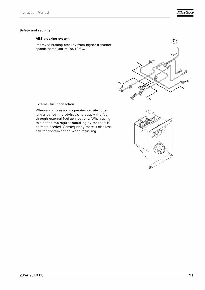
Instruction Manual
Safety and security
ABS breaking system
Improves braking stability from higher transport speeds compliant to 98/12/EC.
External fuel connection
When a compressor is operated on site for a longer period it is advisable to supply the fuel through external fuel connections. When using this option the regular refuelling by tanker it is no more needed. Consequently there is also less risk for contamination when refuelling.
2954 2510 03 91
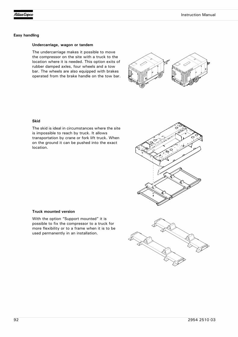
Instruction Manual
Easy handling
Undercarriage, wagon or tandem
The undercarriage makes it possible to move the compressor on the site with a truck to the location where it is needed. This option exits of rubber damped axles, four wheels and a tow bar. The wheels are also equipped with brakes operated from the brake handle on the tow bar.
Skid
The skid is ideal in circumstances where the site is impossible to reach by truck. It allows transportation by crane or fork lift truck. When on the ground it can be pushed into the exact location.
Truck mounted version
With the option “Support mounted” it is possible to fix the compressor to a truck for more flexibility or to a frame when it is to be used permanently in an installation.
92 2954 2510 03
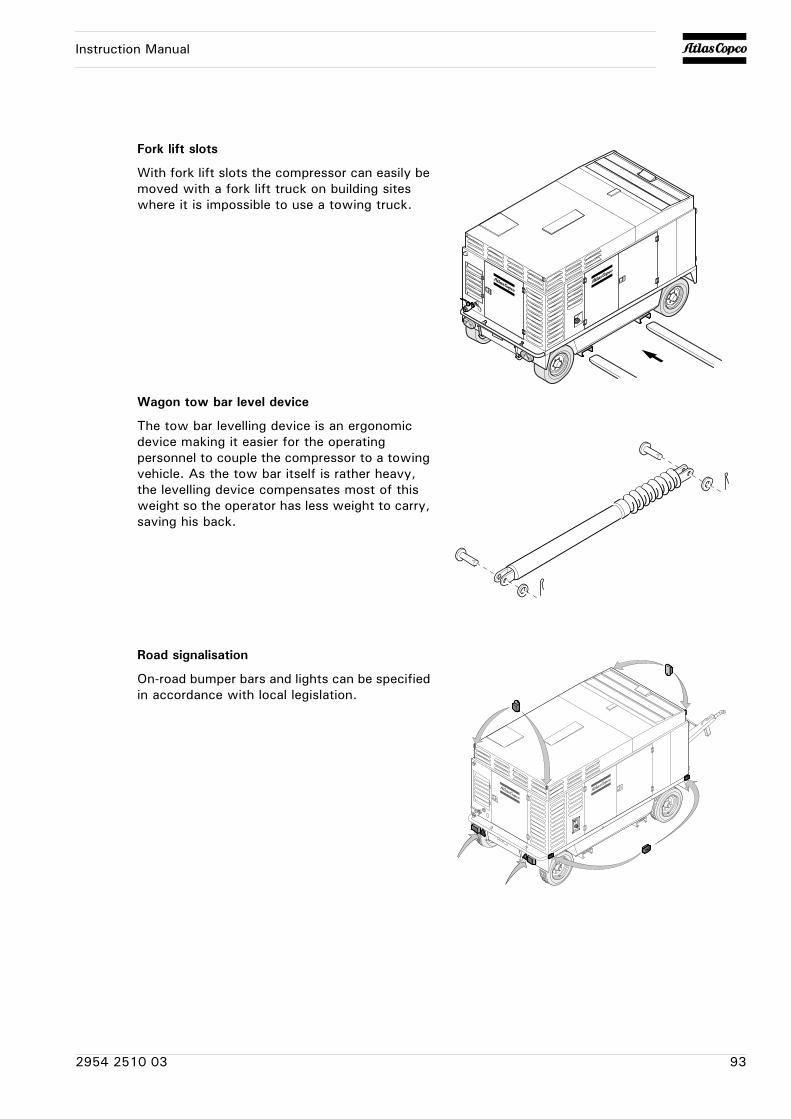
Instruction Manual
Fork lift slots
With fork lift slots the compressor can easily be moved with a fork lift truck on building sites where it is impossible to use a towing truck.
Wagon tow bar level device
The tow bar levelling device is an ergonomic device making it easier for the operating personnel to couple the compressor to a towing vehicle. As the tow bar itself is rather heavy, the levelling device compensates most of this weight so the operator has less weight to carry, saving his back.
Road signalisation
On-road bumper bars and lights can be specified in accordance with local legislation.
2954 2510 03 93
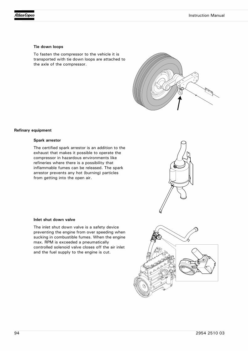
Instruction Manual
Refinary equipment
Tie down loops
To fasten the compressor to the vehicle it is transported with tie down loops are attached to the axle of the compressor.
Spark arrestor
The certified spark arrestor is an addition to the exhaust that makes it possible to operate the compressor in hazardous environments like refineries where there is a possibility that inflammable fumes can be released. The spark arrestor prevents any hot (burning) particles from getting into the open air.
Inlet shut down valve
The inlet shut down valve is a safety device preventing the engine from over speeding when sucking in combustible fumes. When the engine max. RPM is exceeded a pneumatically controlled solenoid valve closes off the air inlet and the fuel supply to the engine is cut.
94 2954 2510 03
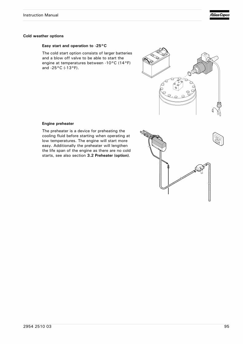
Instruction Manual
Cold weather options
Easy start and operation to -25°C
The cold start option consists of larger batteries and a blow off valve to be able to start the engine at temperatures between -10°C (14°F) and -25°C (-13°F).
Engine preheater
The preheater is a device for preheating the cooling fluid before starting when operating at low temperatures. The engine will start more easy. Additionally the preheater will lengthen the life span of the engine as there are no cold starts, see also section 3.2 Preheater (option).
2954 2510 03 95
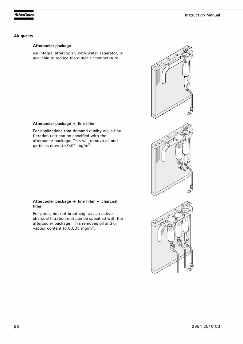
Instruction Manual
Air quality
Aftercooler package
An integral aftercooler, with water separator, is available to reduce the outlet air temperature.
Aftercooler package + fine filter
For applications that demand quality air, a fine filtration unit can be specified with the aftercooler package. This will remove oil and particles down to 0.01 mg/m3.
Aftercooler package + fine filter + charcoal filter
For purer, but not breathing, air, an active charcoal filtration unit can be specified with the aftercooler package. This removes oil and oil vapour content to 0.003 mg/m3.
96 2954 2510 03
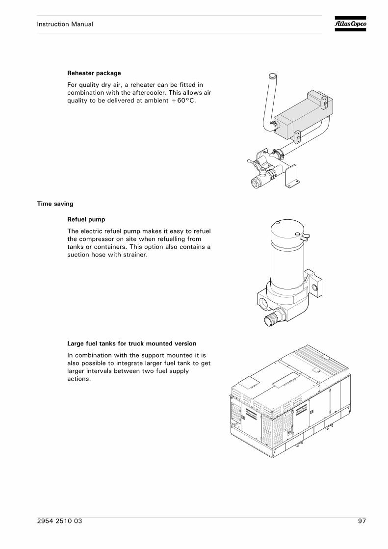
Instruction Manual
Time saving
Reheater package
For quality dry air, a reheater can be fitted in combination with the aftercooler. This allows air quality to be delivered at ambient +60°C.
Refuel pump
The electric refuel pump makes it easy to refuel the compressor on site when refuelling from tanks or containers. This option also contains a suction hose with strainer.
Large fuel tanks for truck mounted version
In combination with the support mounted it is also possible to integrate larger fuel tank to get larger intervals between two fuel supply actions.
2954 2510 03 97
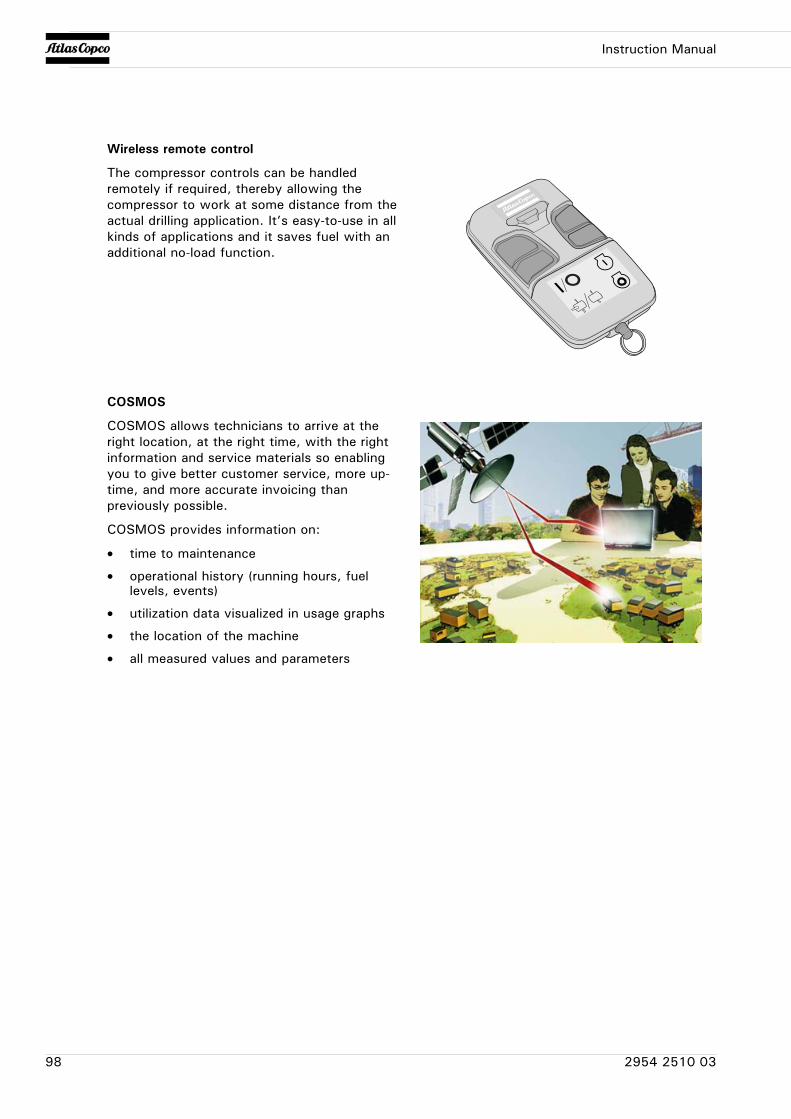
Instruction Manual
Wireless remote control
The compressor controls can be handled remotely if required, thereby allowing the compressor to work at some distance from the actual drilling application. It’s easy-to-use in all kinds of applications and it saves fuel with an additional no-load function.
COSMOS
COSMOS allows technicians to arrive at the right location, at the right time, with the right information and service materials so enabling you to give better customer service, more up-time, and more accurate invoicing than previously possible.
COSMOS provides information on:
• time to maintenance
• operational history (running hours, fuel levels, events)
• utilization data visualized in usage graphs
• the location of the machine
• all measured values and parameters
98 2954 2510 03
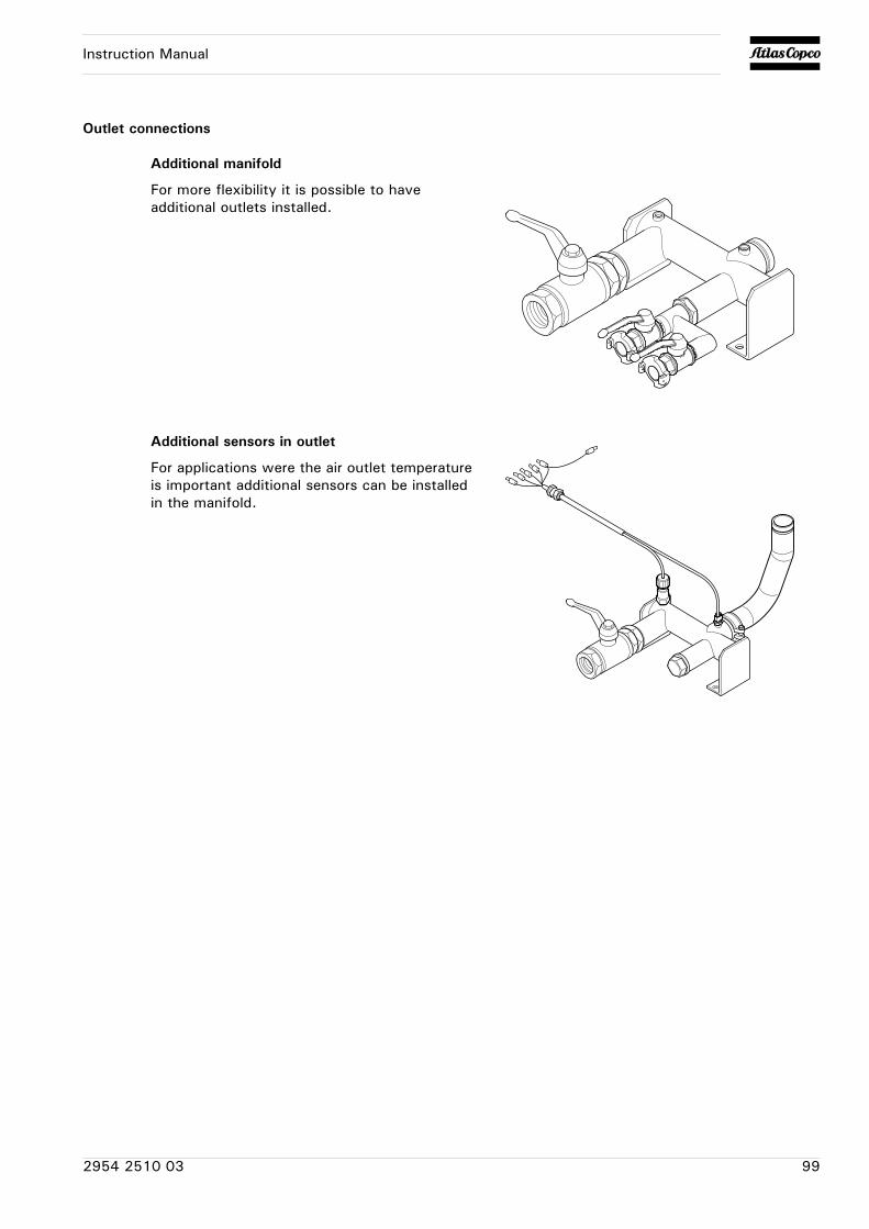
Instruction Manual
Outlet connections
Additional manifold
For more flexibility it is possible to have additional outlets installed.
Additional sensors in outlet
For applications were the air outlet temperature is important additional sensors can be installed in the manifold.
2954 2510 03 99
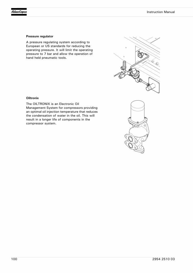
Instruction Manual
Pressure regulator
A pressure regulating system according to European or US standards for reducing the operating pressure. It will limit the operating pressure to 7 bar and allow the operation of hand held pneumatic tools.
Oiltronix
The OILTRONIX is an Electronic Oil Management System for compressors providing an optimal oil injection temperature that reduces the condensation of water in the oil. This will result in a longer life of components in the compressor system.
100 2954 2510 03
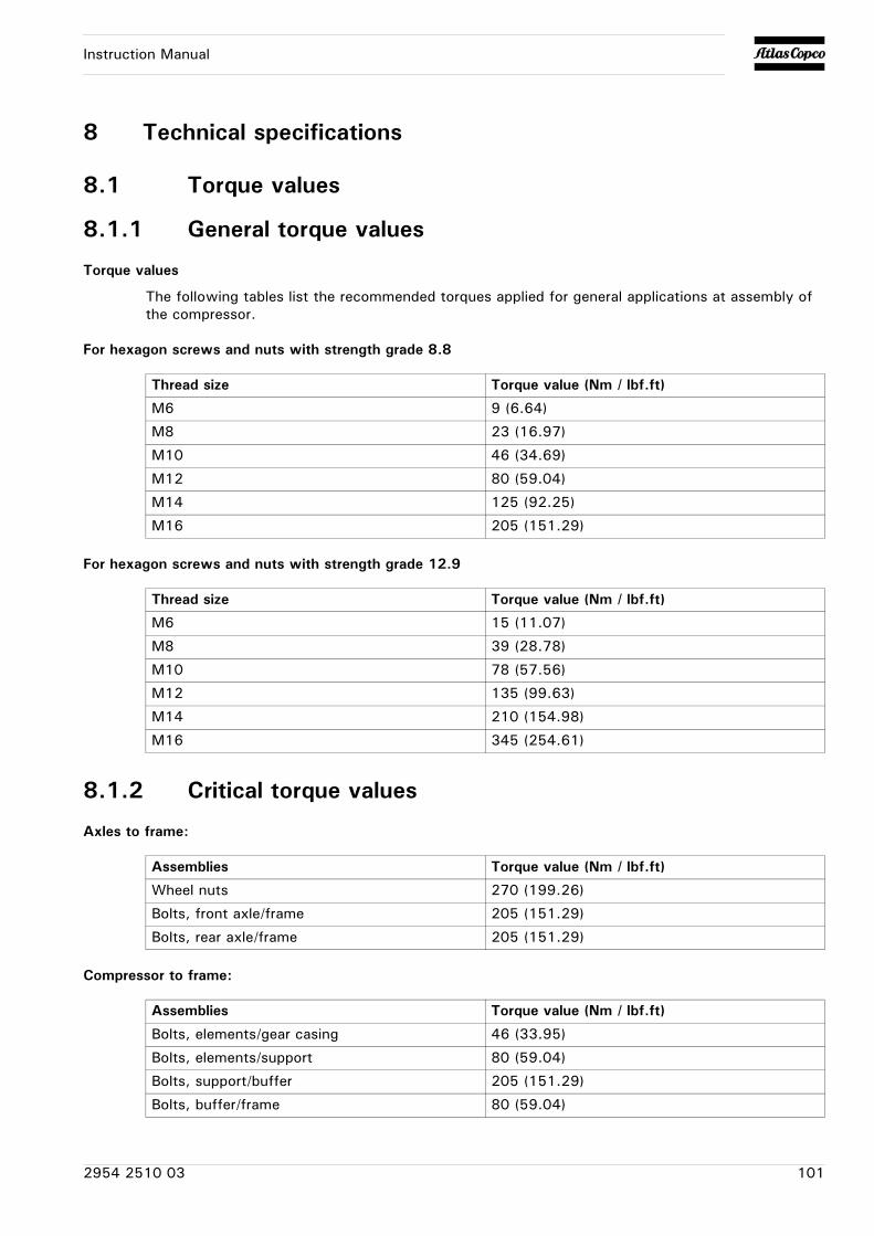
Instruction Manual
8 Technical specifications
8.1 Torque values
8.1.1 General torque values
Torque values
The following tables list the recommended torques applied for general applications at assembly of the compressor.
For hexagon screws and nuts with strength grade 8.8
For hexagon screws and nuts with strength grade 12.9
8.1.2 Critical torque values
Axles to frame:
Compressor to frame:
Thread size Torque value (Nm / lbf.ft)
M6 9 (6.64)
M8 23 (16.97)
M10 46 (34.69)
M12 80 (59.04)
M14 125 (92.25)
M16 205 (151.29)
Thread size Torque value (Nm / lbf.ft)
M6 15 (11.07)
M8 39 (28.78)
M10 78 (57.56)
M12 135 (99.63)
M14 210 (154.98)
M16 345 (254.61)
Assemblies Torque value (Nm / lbf.ft)
Wheel nuts 270 (199.26)
Bolts, front axle/frame 205 (151.29)
Bolts, rear axle/frame 205 (151.29)
Assemblies Torque value (Nm / lbf.ft)
Bolts, elements/gear casing 46 (33.95)
Bolts, elements/support 80 (59.04)
Bolts, support/buffer 205 (151.29)
Bolts, buffer/frame 80 (59.04)
2954 2510 03 101
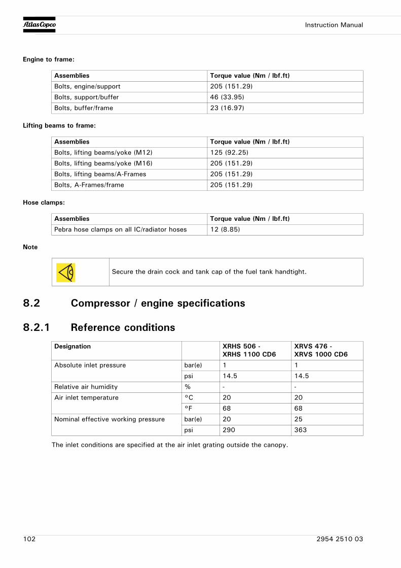
Instruction Manual
Engine to frame:
Lifting beams to frame:
Hose clamps:
Note
8.2 Compressor / engine specifications
8.2.1 Reference conditions
The inlet conditions are specified at the air inlet grating outside the canopy.
Assemblies Torque value (Nm / lbf.ft)
Bolts, engine/support 205 (151.29)
Bolts, support/buffer 46 (33.95)
Bolts, buffer/frame 23 (16.97)
Assemblies Torque value (Nm / lbf.ft)
Bolts, lifting beams/yoke (M12) 125 (92.25)
Bolts, lifting beams/yoke (M16) 205 (151.29)
Bolts, lifting beams/A-Frames 205 (151.29)
Bolts, A-Frames/frame 205 (151.29)
Assemblies Torque value (Nm / lbf.ft)
Pebra hose clamps on all IC/radiator hoses 12 (8.85)
Secure the drain cock and tank cap of the fuel tank handtight.
Designation XRHS 506 - XRHS 1100 CD6
XRVS 476 - XRVS 1000 CD6
Absolute inlet pressure bar(e) 1 1
psi 14.5 14.5
Relative air humidity % - -
Air inlet temperature °C 20 20
°F 68 68
Nominal effective working pressure bar(e) 20 25
psi 290 363
102 2954 2510 03
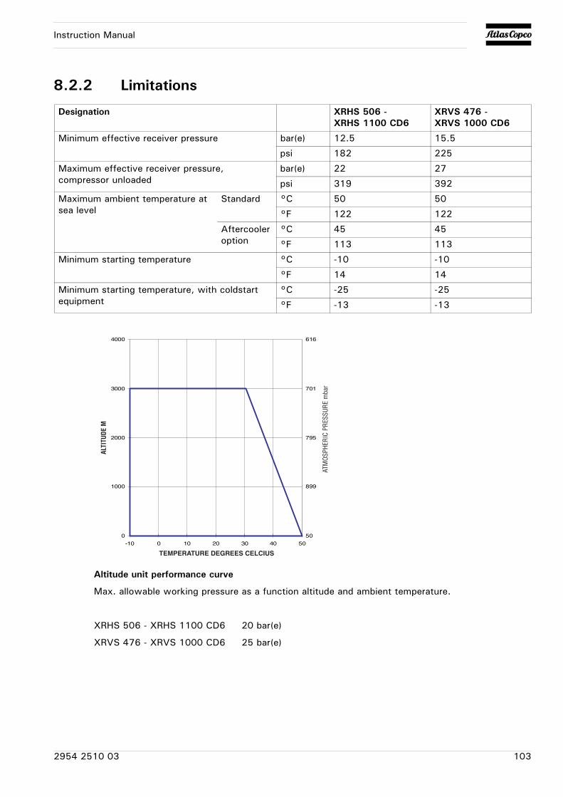
Instruction Manual
8.2.2 Limitations
Altitude unit performance curve
Max. allowable working pressure as a function altitude and ambient temperature.
XRHS 506 - XRHS 1100 CD6 20 bar(e)
XRVS 476 - XRVS 1000 CD6 25 bar(e)
Designation XRHS 506 - XRHS 1100 CD6
XRVS 476 - XRVS 1000 CD6
Minimum effective receiver pressure bar(e) 12.5 15.5
psi 182 225
Maximum effective receiver pressure, compressor unloaded
bar(e) 22 27
psi 319 392
Maximum ambient temperature at sea level
Standard °C 50 50
°F 122 122
Aftercooler option
°C 45 45
°F 113 113
Minimum starting temperature °C -10 -10
°F 14 14
Minimum starting temperature, with coldstart equipment
°C -25 -25
°F -13 -13
50
616
701
795
899
0
1000
2000
3000
4000
-10 0 10 20 30 40 50
ATM
OSPH
ERIC
PRE
SSUR
E m
bar
ALTI
TUDE
M
TEMPERATURE DEGREES CELCIUS
2954 2510 03 103
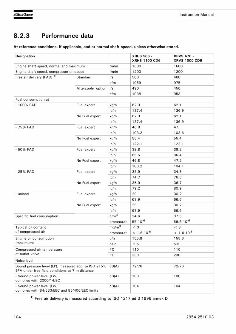
Instruction Manual
8.2.3 Performance data
At reference conditions, if applicable, and at normal shaft speed, unless otherwise stated.
1) Free air delivery is measured according to ISO 1217 ed.3 1996 annex D
Designation XRHS 506 - XRHS 1100 CD6
XRVS 476 - XRVS 1000 CD6
Engine shaft speed, normal and maximum r/min 1600 1600
Engine shaft speed, compressor unloaded r/min 1200 1200
Free air delivery (FAD) 1) Standard l/s 500 460
cfm 1059 975
Aftercooler option l/s 490 450
cfm 1038 953
Fuel consumption at
- 100% FAD Fuel expert kg/h 62.3 62.1
lb/h 137.4 136.9
No Fuel expert kg/h 62.3 62.1
lb/h 137.4 136.9
- 75% FAD Fuel expert kg/h 46.8 47
lb/h 103.2 103.6
No Fuel expert kg/h 55.4 55.4
lb/h 122.1 122.1
- 50% FAD Fuel expert kg/h 38.8 39.2
lb/h 85.5 86.4
No Fuel expert kg/h 46.8 47.2
lb/h 103.2 104.1
- 25% FAD Fuel expert kg/h 33.9 34.6
lb/h 74.7 76.3
No Fuel expert kg/h 35.9 36.7
lb/h 79.2 80.9
- unload Fuel expert kg/h 29 30.2
lb/h 63.9 66.6
No Fuel expert kg/h 29 30.2
lb/h 63.9 66.6
Specific fuel consumption g/m3 34.6 37.5
dram/cu.ft 55 10-6 59.6 10-6
Typical oil contentof compressed air
mg/m3 < 3 < 3
dram/cu.ft < 1.6 10-6 < 1.6 10-6
Engine oil consumption(maximum)
g/h 155.8 155.3
oz/h 5.5 5.5
Compressed air temperatureat outlet valve
°C 110 110
°F 230 230
Noise level
Sound pressure level (LP), measured acc. to ISO 2151/EPA under free field conditions at 7 m distance
dB(A) 72/76 72/76
- Sound power level (LW)complies with 2000/14/EC
dB(A) 100 100
- Sound power level (LW)complies with 84/533/EEC and 85/406/EEC limits
dB(A) 104 104
104 2954 2510 03
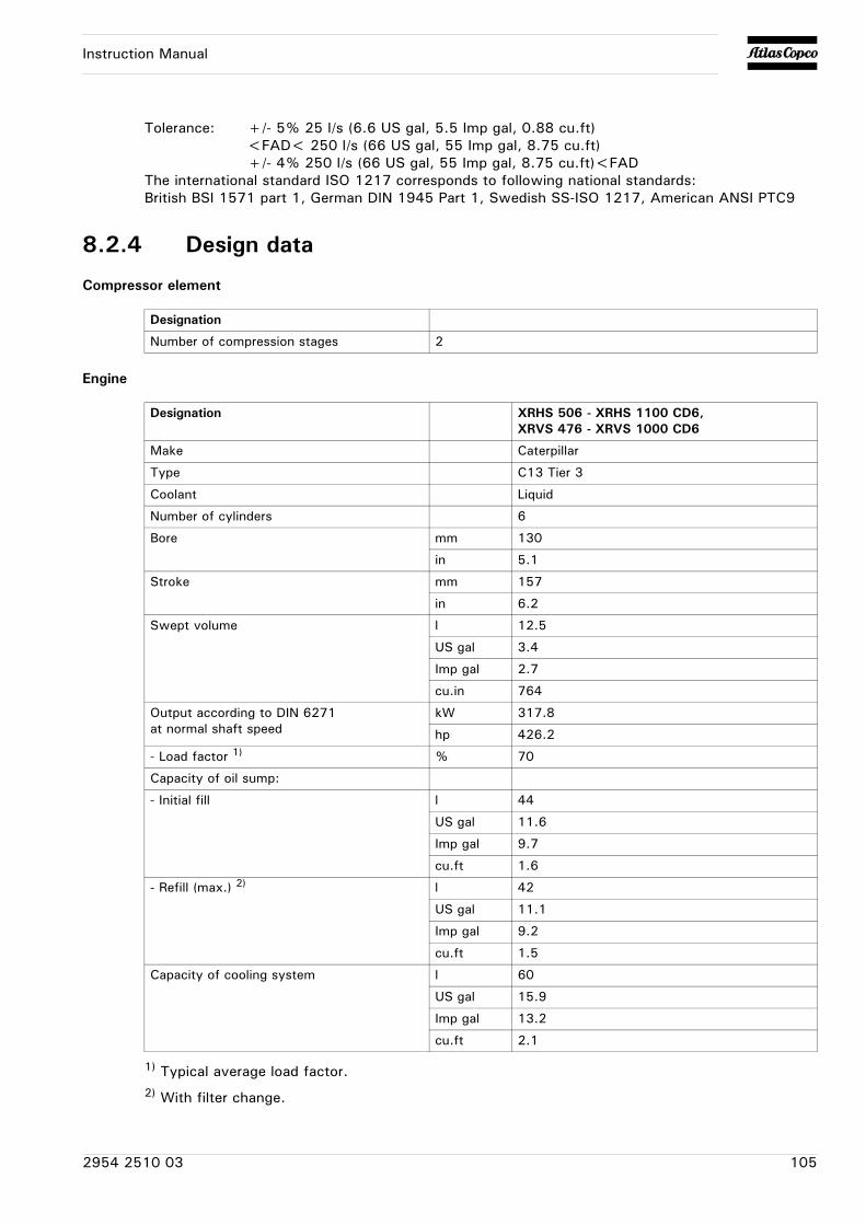
Instruction Manual
Tolerance: +/- 5% 25 l/s (6.6 US gal, 5.5 Imp gal, 0.88 cu.ft)<FAD< 250 l/s (66 US gal, 55 Imp gal, 8.75 cu.ft)+/- 4% 250 l/s (66 US gal, 55 Imp gal, 8.75 cu.ft)<FAD
The international standard ISO 1217 corresponds to following national standards:British BSI 1571 part 1, German DIN 1945 Part 1, Swedish SS-ISO 1217, American ANSI PTC9
8.2.4 Design data
Compressor element
Engine
1) Typical average load factor.2) With filter change.
Designation
Number of compression stages 2
Designation XRHS 506 - XRHS 1100 CD6,XRVS 476 - XRVS 1000 CD6
Make Caterpillar
Type C13 Tier 3
Coolant Liquid
Number of cylinders 6
Bore mm 130
in 5.1
Stroke mm 157
in 6.2
Swept volume l 12.5
US gal 3.4
Imp gal 2.7
cu.in 764
Output according to DIN 6271at normal shaft speed
kW 317.8
hp 426.2
- Load factor 1) % 70
Capacity of oil sump:
- Initial fill l 44
US gal 11.6
Imp gal 9.7
cu.ft 1.6
- Refill (max.) 2) l 42
US gal 11.1
Imp gal 9.2
cu.ft 1.5
Capacity of cooling system l 60
US gal 15.9
Imp gal 13.2
cu.ft 2.1
2954 2510 03 105
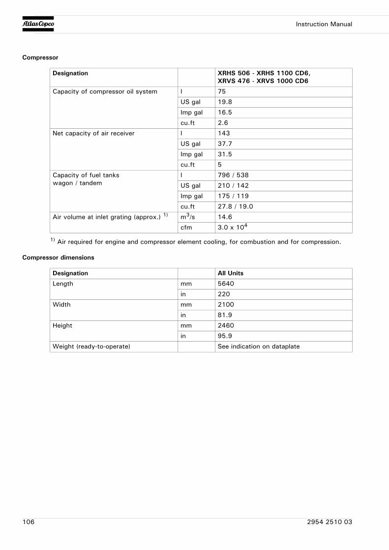
Instruction Manual
Compressor
1) Air required for engine and compressor element cooling, for combustion and for compression.
Compressor dimensions
Designation XRHS 506 - XRHS 1100 CD6,XRVS 476 - XRVS 1000 CD6
Capacity of compressor oil system l 75
US gal 19.8
Imp gal 16.5
cu.ft 2.6
Net capacity of air receiver l 143
US gal 37.7
Imp gal 31.5
cu.ft 5
Capacity of fuel tankswagon / tandem
l 796 / 538
US gal 210 / 142
Imp gal 175 / 119
cu.ft 27.8 / 19.0
Air volume at inlet grating (approx.) 1) m3/s 14.6
cfm 3.0 x 10⁴
Designation All Units
Length mm 5640
in 220
Width mm 2100
in 81.9
Height mm 2460
in 95.9
Weight (ready-to-operate) See indication on dataplate
106 2954 2510 03
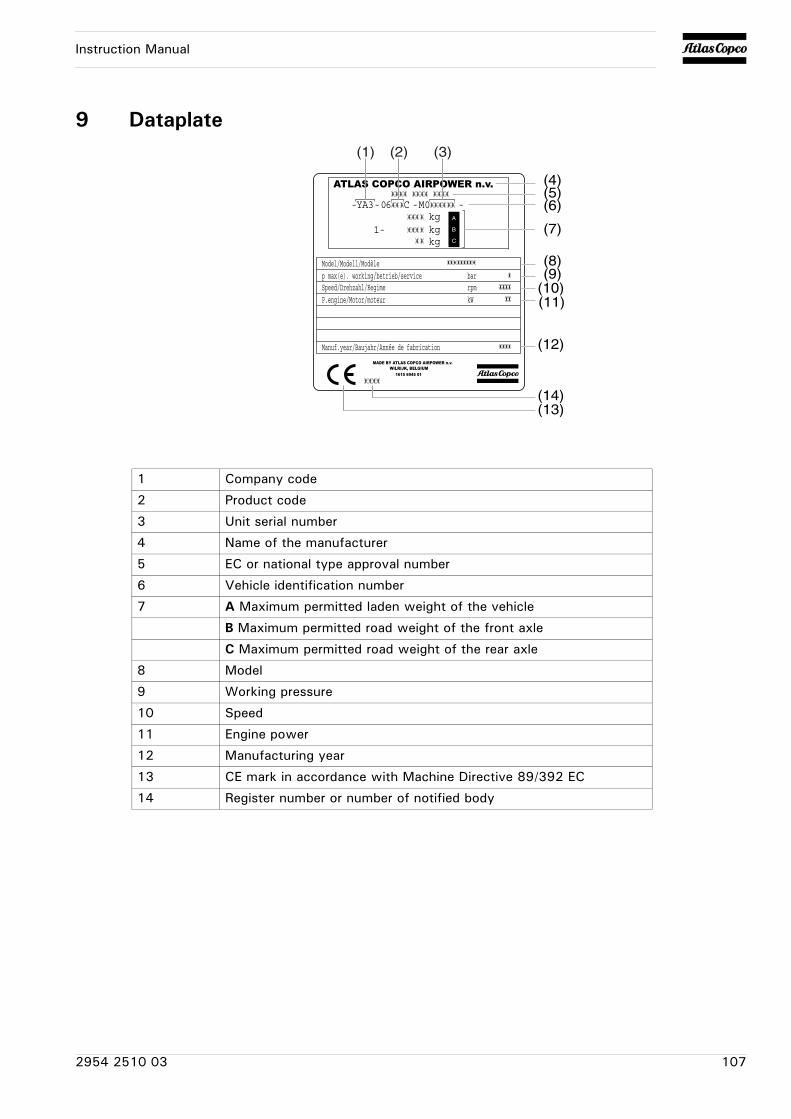
Instruction Manual
9 Dataplate(1) (2) (3)
(4)(5)(6)
(7)
(8)(9)
(10)(11)
(12)
(14)(13)
1 Company code
2 Product code
3 Unit serial number
4 Name of the manufacturer
5 EC or national type approval number
6 Vehicle identification number
7 A Maximum permitted laden weight of the vehicle
B Maximum permitted road weight of the front axle
C Maximum permitted road weight of the rear axle
8 Model
9 Working pressure
10 Speed
11 Engine power
12 Manufacturing year
13 CE mark in accordance with Machine Directive 89/392 EC
14 Register number or number of notified body
2954 2510 03 107
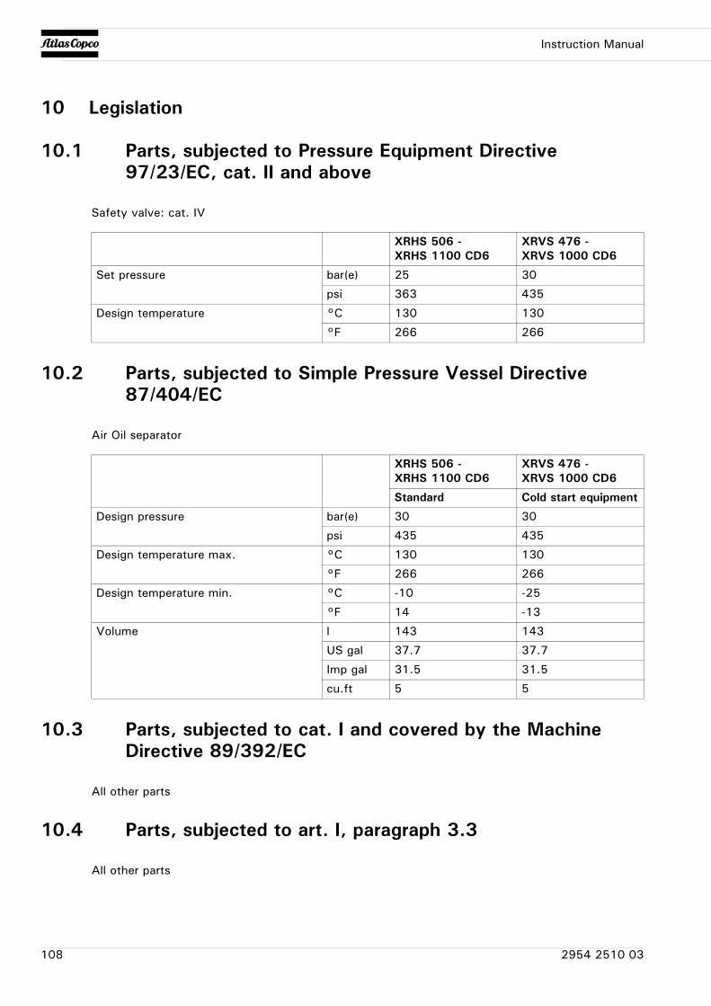
Instruction Manual
10 Legislation
10.1 Parts, subjected to Pressure Equipment Directive 97/23/EC, cat. II and above
Safety valve: cat. IV
10.2 Parts, subjected to Simple Pressure Vessel Directive 87/404/EC
Air Oil separator
10.3 Parts, subjected to cat. I and covered by the Machine Directive 89/392/EC
All other parts
10.4 Parts, subjected to art. I, paragraph 3.3
All other parts
XRHS 506 - XRHS 1100 CD6
XRVS 476 - XRVS 1000 CD6
Set pressure bar(e) 25 30
psi 363 435
Design temperature °C 130 130
°F 266 266
XRHS 506 - XRHS 1100 CD6
XRVS 476 - XRVS 1000 CD6
Standard Cold start equipment
Design pressure bar(e) 30 30
psi 435 435
Design temperature max. °C 130 130
°F 266 266
Design temperature min. °C -10 -25
°F 14 -13
Volume l 143 143
US gal 37.7 37.7
Imp gal 31.5 31.5
cu.ft 5 5
108 2954 2510 03
Instruction Manual
11 Disposal
11.1 General
When developing products and services, Atlas Copco tries to understand, address, and minimize the negative environmental effects that the products and services may have, when being manufactured, distributed, and used, as well as at their disposal.
Recycling and disposal policy are part of the development of all Atlas Copco products. Atlas Copco company standards determine strict requirements.
Selecting materials the substantial recyclability, the disassembly possibilities and the separability of materials and assemblies are considered as well as the environmental perils and dangers to health during the recycling and disposal of the unavoidable rates of not recyclable materials.
Your Atlas Copco compressor consists for the most part of metallic materials, that can be remelted in steelworks and smelting works and that is therefore almost infinite recyclable. The plastic used is labelled; sorting and fractioning of the materials for recycling in the future is forseen.
Note
11.2 Disposal of materials
Dispose contaminated substances and material separately, according to local applicable environmental legislations.
Before dismantling a machine at the end of its operating lifetime drain all fluids and dispose of according the applicable local disposal regulations.
Remove the batteries. Do not throw batteries into the fire (explosion risk) or into the residual waste. Separate the machine into metal, electronics, wiring, hoses, insulation and plastic parts.
Dispose all components according to the applicable disposal regulations.
Remove spilled fluid mechanically; pick up the rest with absorbing agent (for example sand, sawdust) and dispose it according the applicable local disposal regulations. Do not drain into the sewage system or surface water.
This concept can only succeed with your help. Support us by disposing professionally. By assuring a correct disposal of the product you help to prevent possible negative consequences for environment and health, that can occur with an inappropriate waste handling.
Recycling and re-usage of material helps to preserve natural resources.
2954 2510 03 109
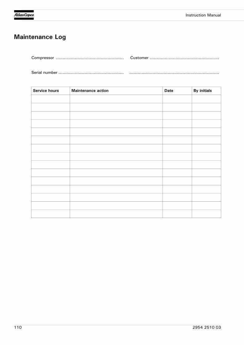
Instruction Manual
Maintenance Log
Compressor .................................................. Customer ...................................................
Serial number ................................................ ..................................................................
Service hours Maintenance action Date By initials
110 2954 2510 03

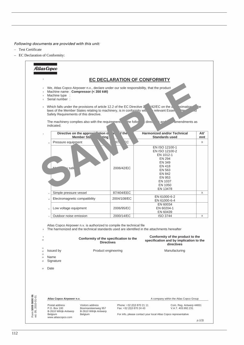
1
Following documents are provided with this unit:
– Test Certificate– EC Declaration of Conformity:
Atlas Copco Airpower n.v. puorG ocpoC saltA eht nihtiw ynapmoc A
Postal address Visitors address Phone: +32 (0)3 870 21 11 Com. Reg. Antwerp 44651 P.O. Box 100 Boomsesteenweg 957 Fax: +32 (0)3 870 24 43 V.A.T. 403.992.231 B-2610 Wilrijk-Antwerp B-2610 Wilrijk-Antwerp
evitatneserper ocpoC saltA lacol ruoy tcatnoc esaelp ,ofni roF muigleB muigleBwww.atlascopco.com
p.1(3)
Form
5009
060
0 06
ed. 0
5, 2
010-
01-0
1
1 EC DECLARATION OF CONFORMITY2 We, Atlas Copco Airpower n.v., declare under our sole responsibility, that the product 3 Machine name : Compressor (< 350 kW) 4 Machine type : 5 Serial number :
Which falls under the provisions of article 12.2 of the EC Directive 2006/42/EC on the approximation of the laws of the Member States relating to machinery, is in conformity with the relevant Essential Health and Safety Requirements of this directive.
The machinery complies also with the requirements of the following directives and their amendments as indicated.
Directive on the approximation of laws of the Member States relating to
Harmonized and/or Technical Standards used
Att’mnt
a. Pressure equipment 97/23/EC X
b. CE/24/6002 ytefas yrenihcaM
EN ISO 12100-1 EN ISO 12100-2
EN 1012-1 EN 294 EN 349 EN 418 EN 563 EN 842 EN 953
EN 1037 EN 1050 EN 13478
c. CEE/404/78 lessev erusserp elpmiS X
d. Electromagnetic compatibility 2004/108/EC EN 61000-6-2 EN 61000-6-4
e. Low voltage equipment 2006/95/EC EN 60034
EN 60204-1 EN 60439
f. Outdoor noise emission 2000/14/EC ISO 3744 X
6
7
Atlas Copco Airpower n.v. is authorized to compile the technical file 8 The harmonized and the technical standards used are identified in the attachments hereafter
9
10 Conformity of the specification to the Directives
Conformity of the product to the specification and by implication to the
directives11
12
13
gnirutcafunaM gnireenigne tcudorP yb deussI
14 Name15 Signature
16 Date
12


Pri
nte
d in
Bel
giu
m 0
1/2
01
0 - 2
95
4 2
510
03
www.atlascopco.com