Embed Size (px)
Citation preview

1
25% Piper Pawnee Designed by: Bill Hempel
Specifications:
Wing span: 108”
Wing area: 1575 Sq. inches
Flying weight: 19-20 pounds
Motor: 30cc up to 50cc

2
Thank you for purchasing a Bill Hempel Team Edge aircraft. We strive to build high quality and great flying aircraft. We have used our years of experience in the hobby to design and build aircraft that are competitive at the highest levels of aerobatic competitions and that will last for many flying seasons. We suggest that you read through the manual before starting the assembly. If you have any questions or concerns please don’t hesitate to e-mail us at [email protected] Thank you, Bill Hempel
Billhempel.com assumes no liability for any damage resulting from the user assembled product. By the act of using the assembled product, the user accepts all resulting liability. The purchaser or designated person flying this aircraft accepts all liability associated with the use of this product. This product is sold as is and the purchaser accepts any and all responsibility for structural or mechanical failures. Because of the stresses that are associated with aerobatic flight there is no warranty provided and bill.hempel.com cannot be held liable.
WARNING: Radio Control Model aircraft are not toys. If improperly used, it can cause serious injury or death. Fly only in open areas, and at AMA (Academy of Model Aeronautics) approved flying sites. AMA Safety Code must be followed. Follow all instructions included with
your plane, radio, and engine. The purchaser accepts all liabilities.

3
25% Pawnee Instructions
Covering
1. Iron down all covering. Due to different environments between the factory and your location, it
is a good idea to spend at least an hour or so going over the entire model to verify all of the
material is properly adhered to the wood surface. Hint: Using a heat gun and a soft cloth you
can accomplish the same goal by heating an area them immediately rubbing it down with the
soft cloth.
2. Using a soldering iron or something similar, carefully remove the covering from the fuselage
area for the stab, elevator servo and rudder servo, wing slot, etc.. Open holes on bottom of
fuselage for landing gear and tail wheel. Note: Only cut the lower rudder servo hole in the rear
of the fuselage if you are planning on using the rudder servo in the rear part of the fuselage.
There is a provision under the canopy hatch for a rudder servo there as well for a pull/pull set
up. If you are going to install the rudder servo in the rear of the fuselage, only open ONE hole on
either side of the fuselage. Hint: Using a 28-35cc motor then you would probably want to install
the rudder servo under the canopy area to help with proper CG.
Aluminum Wing Spar
1. Install your aluminum wing spar using (2) 6-32” socket head bolt and washer. Use Loctite if you
do not plan on removing this spar for transporting the model.
2. If there are any sharp edges on the spar you can carefully file these smooth to prevent any
issues sliding the wings on or off. Note: The spar can be installed at any time during the
construction.

4
Landing Gear
1. Install the landing gear. (This step can be done at any time during construction.) Locate your
landing gear legs. You will have to remove the mounting brackets from the gear legs and install
these pieces fist. Once the mounting brackets are on then you can attach your gear legs. Please
use Loctite on all bolts. Inside the fuselage you will install the springs, washers and lock nut. This
suspension will allow the gear to absorb the firm landings.
2. Once the gear legs are mounted you can run a drill bit (match bolt diameter) through the
alignment bolt hole into the fuselage. This will correct any alignment issues from the factory.
Note: in this picture we installed black rubber washers but it was determined they were not
needed.
3. Wheels and axles. You will want to test fit your wheels on the axle and tighten the screw into
the axle. This will mark the axle so you will see where the contact point is with the screw.
Remove the axle after your trail fit and file a flat spot onto the axle. This will help retain your
wheels and axles from falling off during flight in the event the screw becomes a little lose.
Remember to always check this screw prior to flight just to be sure it will not come off.
4. Reinstall wheels while using Loctite on the axle screw. Use some type of lubricating grease on
the axle to extend the life of the wheel bearings.
5. Screw wheel cover cap onto the outside of the wheels.
Tail Wheel
1. Install the tail wheel assembly into the rear part of the fuselage. Locate the wire straps and drill
the hole for the brackets.
2. Remove the screws and tail wheel and apply some thin CA into the holes to strengthen the
wood.
3. Reinstall and mount your tail wheel assembly. Hint: 2 small pieces of fuel line on the wire under
the mounts will help with any slop.

5
Rudder Steering Arm
1. Install the metal steering arm to the bottom of the rudder as pictured. You will have to cut the
bottom of the rudder a little to have a flat area to screw into. Once cut, soak with thin CA to
strengthen the wood. Screw steering arm into place.
Tail Wheel Springs
1. Locate the tail wheel springs and open from bag.
2. You will want to make sure the tail wheel is properly aligned with the rudder for a straight taxi.
Hint: Tape the rudder straight with the fin while the springs are installed.
3. Using your fingers your will want to pull the spring apart some to about 3” width.

6
4. Install spring between the tail wheel and rudder, you can pull apart and even compress the
springs once on the airplane to properly align the tail wheel with the rudder.
Tail Surfaces
1. Remove the elevators from the stab and set aside. Measure and locate the centerline of the
stab.
2. Slide the stab onto the fuselage and center the line drawn with the fuselage centerline. Using a
pen, trace the fuselage outline onto the stab. Remove stab and then remove the covering on the
center of the stab inside the lines you drew.
3. Install stab with epoxy or similar type glue and center. Measure your stab location with a ruler
while the glue dries to verify the stab is properly centered. Also check to make sure the stab and
vertical fin are 90 degrees to each other.

7
4. Install all hinges using your preferred hinge type glue. Hint: you can insert a hinge point into
your drill and hone out the holes to a perfect fit prior to gluing in. Also a soldering iron can really
clean up the holes and have a nice look.
5. Install all 4mm control horns. There are 2-sizes! The shorter ones are for the elevator. Note: the
4mm control arms comes with small diameter gold anodized washer that is about 0.25” thick.
Do not install these as they only make your bolt stick up higher in the airflow out the top side of
the wings. We will use these pieces later on in the build for the wing struts.
6. Install the elevators and rudder into place with glue. Hint: you can use a drop of oil on the pin of
the hinge to prevent the glue from locking up your hinges when it dries. We really like using
White Gorilla Glue for installing these hinges, dries very fast.
Tail Wires
1. Tail wires must be installed to safely fly this model. Do-Not attempt to fly model without these
Installed. Install wires and hardware as shown. There are hardwood blocks built into the fin and
stab for bolts to go through. You may need a small flashlight on one side of the surface while
looking on the other to find the block.
2. With your flashlight shining through from the other side of the surface, mark where the hole is
on the covering.
3. Using a soldering iron, open the holes in the covering

8
4. There are aluminum tail wire brackets that will need to be bent in the proper angle to align with
the flying wire once installed. Using pliers or a small vise, bend each bracket the proper angle.
5. Using the supplied bolt, nut and washer, install the metal brackets on each side of the stab and
fin. Note: There are (2pcs) 4-40 adjustable connector/clevis per side of stab for both the top and
bottom.
\
Elevator Pushrod/Servo
1. There is (1pcs) C/F rod to be used as the elevator pushrod. This should be cut into (2pcs)
measuring 3 7/8” long. With both 4-40 end connectors on the C/F rod the overall length will be
5.5” long.
2. There are 2 ways to secure the 4-40 couplers onto the C/F rod. 1-use CA and glue the 4-40
coupler then drill the holes and install 2-56” bolt and nut (Not supplied) through the holes in the
coupler (see pictures). 2-Use JB Weld (24hr one) and glue the 4-40 rod ends onto the C/F rod.
3. Once the rod ends are secure, install the ball links to each end and adjust for proper length.
Note: the output shaft of the elevator servo should be mounted so it is to the rear of the
aircraft. If it is not in this position there will not be sufficient length of C/F pushrod to make 2
pieces of equal length.

9
Note: Use this piece: The kit now comes with this mounting bracket for the bottom of the
fuselage tail wires.
Wings
1. Remember to go over the wing also with an iron or a heat gun to verify all the covering is
bonded well to the surface. Hint: You should be able to see the actual wood grain in the film
when looking closely, this will show good adhesion to the surface.
2. Using a soldering iron or knife, open the (2) servo holes on the bottom of the wing. Locate and
open the hard points in the control surface for the 4mm control arm.
10
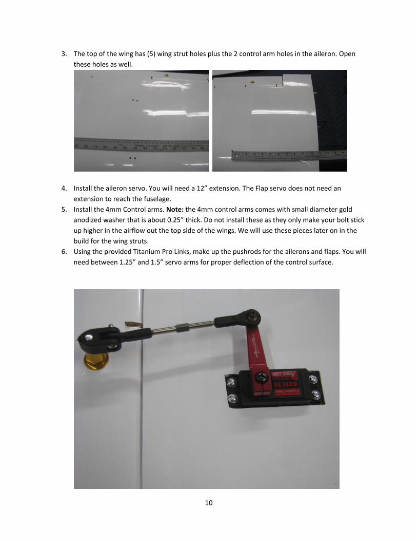
3. The top of the wing has (5) wing strut holes plus the 2 control arm holes in the aileron. Open
these holes as well.
4. Install the aileron servo. You will need a 12” extension. The Flap servo does not need an
extension to reach the fuselage.
5. Install the 4mm Control arms. Note: the 4mm control arms comes with small diameter gold
anodized washer that is about 0.25” thick. Do not install these as they only make your bolt stick
up higher in the airflow out the top side of the wings. We will use these pieces later on in the
build for the wing struts.
6. Using the provided Titanium Pro Links, make up the pushrods for the ailerons and flaps. You will
need between 1.25” and 1.5” servo arms for proper deflection of the control surface.

11
Wing Struts
1. Install both wing panels on the fuselage and install wing bolts. We are going to install and set up
the wing struts as if we are preparing for flight.
2. Locate the small metal bracket that goes into the fuselage. You will see it has (2) holes drilled
into one end.
3. Using the (2) screw provided and Loctite, install these brackets inside the fuselage. The
mounting plates for these are above the fuel tank area. This will be the most difficult task in the
build so far. Once installed the angle part of the bracket should point down or towards the wing
surface.

12
4. Find the mounting brackets and install into the outer wing are. The diagonal cut of the
attachment bracket faces the wing tip.
5. In the kit you will find the wing strut wrapped in (2) separate packages. Unwrap these and you
will notice a front and rear strut. These (2) struts will slide and bolt together near the fuselage.
6. Temporarily mate the (2) struts together and insert the 6-32” bolt and nut. The trailing edge
strut will slide into the Leading Edge strut. Then insert into the fuselage mounting bracket.

13
7. Temporarily use the (4) strut bracket bolt (longer ones) and insert the struts into the outer wing
brackets. Remember those gold anodized washers I suggested you not install? This is where we
will use them. Remember to keep all mounting screws loose until we tweak the struts into
position. Note: Some flexing or twisting of the wings struts may be necessary to get proper
alignment of wing brackets.
8. Once all bolts are in place and everything looks correct, tighten bolts. For the wing brackets you
should remove and apply Loctite one bolt at a time to permanently attach these. Note: The
bolts that go through the hollow wing struts should only be snugged. Do not over tighten these
bolts as this will cause compression of the strut and damage the strut. The bolt and nut should
only be tight enough so you cannot turn the bolt by hand.

14
9. After the wing struts are mounted you can then attach the inner strut. Using the 6-32” bolt and
nut provided install the claps and bolts as shown in picture.
10. Drill the undrilled hole in the strut to the fuselage bracket. Then insert the 6-32” bolt. This
completes the wing strut assembly. All struts should fit perfectly now as you install or remove
the wing from the fuselage.
11. To remove wing, remove only the (1) 6-32” bolt at the fuselage to the wing strut, plus the 2-
wing bolts inside the fuselage. The wing panel will slide off the spar as a whole unit. The wing
struts can then be folded by pulling the inner strut wire out of the bracket. No additional bolts
should have to be removed.

15
Engine
1. Place your cowl on the fuselage and measure the distance between the firewall and the
spinner ring of the cowl. Then measure your motors length and determine how long your
stand offs will need to be. Note: For this prototype pictured in this manual, the 3W-50i
required a 1.0” standoff to have the proper distance to spinner cowl ring.
2. Locate the engine template from the manufactures website and print out. Hint: Make sure
you are printing 1:1 scale and not “fit to page”……
3. With the template printed out you will need to cut out a small square on the template so
you can align the centerline marks on the firewall with the paper one. Use 3M or similar to
temporarily attach the template to the motor box.

16
4. Drill out your engine mounting holes. Also cut out any additional area you will need to fit or
pass through your carburetor.
5. Mount your motor. Hint: Using “T” nuts in the firewall is a great idea; if you use lock-nuts
behind the “T” nuts your motor bolts will never come loose accidentally.
6. Throttle Servo: This model does not have a predetermined servo cut out as there are many
different motors and carburetors that are very different for servo linkage. Using the Secraft
side servo mount (pictured) is a fast and easy way to mount any throttle or choke servo.

17
7. We chose to mount our throttle servo close to the carburetor so it would not interfere with
the 24 ounce fuel tank we are installing. Smaller fuel tanks can be used with smaller size
motor selections.
8. Mount Fuel tank. Using sponge type foam under the tank use Velcro or plastic tied down
straps to secure.
9. Install fueling Dots and overflow/vent line and fuel lines.
10. Depending on the size of the ignition module, you can mount this under the fuel tank area
or on the side/top of the motor box.
11. We mounted our ignition battery next to our throttle servo with padded foam and Velcro.
With the short nose length of this model we wanted to keep this battery up front to help
with the CG.
12. Mount ignition switch using the same method for the RX switch.

18
13. Once everything is mounted, you can fit your cowl and muffler/spark plug cut out.
14. Temporarily mount your muffler to the engine, using hard paper or cardboard make a
template to locate the muffler holes and spark plug. You will need to secure this to the
fuselage while you remove the muffler and install the cowl. This will allow you precise
measurements of where to cut your holes.

19
15. If you are using a Pitts Style muffler you will have to remove the lower cross piece of wood
on the cowl. Once removed, smooth out edges and soak with thin CA to strengthen the
wood former.
16. Cut out the front air inlet area. This will really help keep your engine from overheating. For
(2) cylinder motors this is not necessary.

20
17. Once everything is complete in the engine compartment area, mount your cowl, propeller
and spinner. This should basically complete your model. Go back through all of your
equipment and just verify everything looks correct.
Center of Gravity
1. The CG should be between 3.5” and 4.5” rearward of the leading edge of the wing. We are
looking for a cg between 25% - 30% of the wing cord. Once flown the CG can be adjusted for
your flying tastes. We moved our RX battery next to the receiver to get ours to balance
properly.
Control Throws
These are our recommended control throws for this model.
Aileron: 18 degrees up/down for Low Rate, 25 degrees High Rate
Elevator: 15 degrees up/down for Low Rate and 21 degrees High rate
Rudder: 25 degrees for left/right for Low Rate and as much as possible for High Rate.
Finished Weight
This model should come out between 19-20 pounds ready to fly. Depending upon the type
of equipment selected, size of motor, fuel tank and size/type of batteries will have an effect
on the finished weight of the model.

21
Thank you for your purchase. This is a great flying machine that will last you many great
flights. If you have any questions regarding the assembly process or set up questions please
feel free to contact us at www.billhempel.com
Thank you,
Bill Hempel
25% Piper Pawnee