Embed Size (px)
Citation preview
2.3 Creation of Models
2.3 Creation of Models
This section explains how to create workpiece models and tool models using the CAD func-tions.
2.3.1 Creating a Workpiece and a Workpiece Stand
Follow the flowchart below to create a workpiece and its stand.
Create workpiece stand modelfile in Cad Tree.
Start
Add BOX model in file data editing dialog box.
Set model size and positionin BOX Edit dialog box.
Create workpiece model file in Cad Tree.
Add parts in the file data editing dialog box.
Set sizes and positions of parts in BOX Edit dialog box.
End
34/498
2.3 Creation of Models
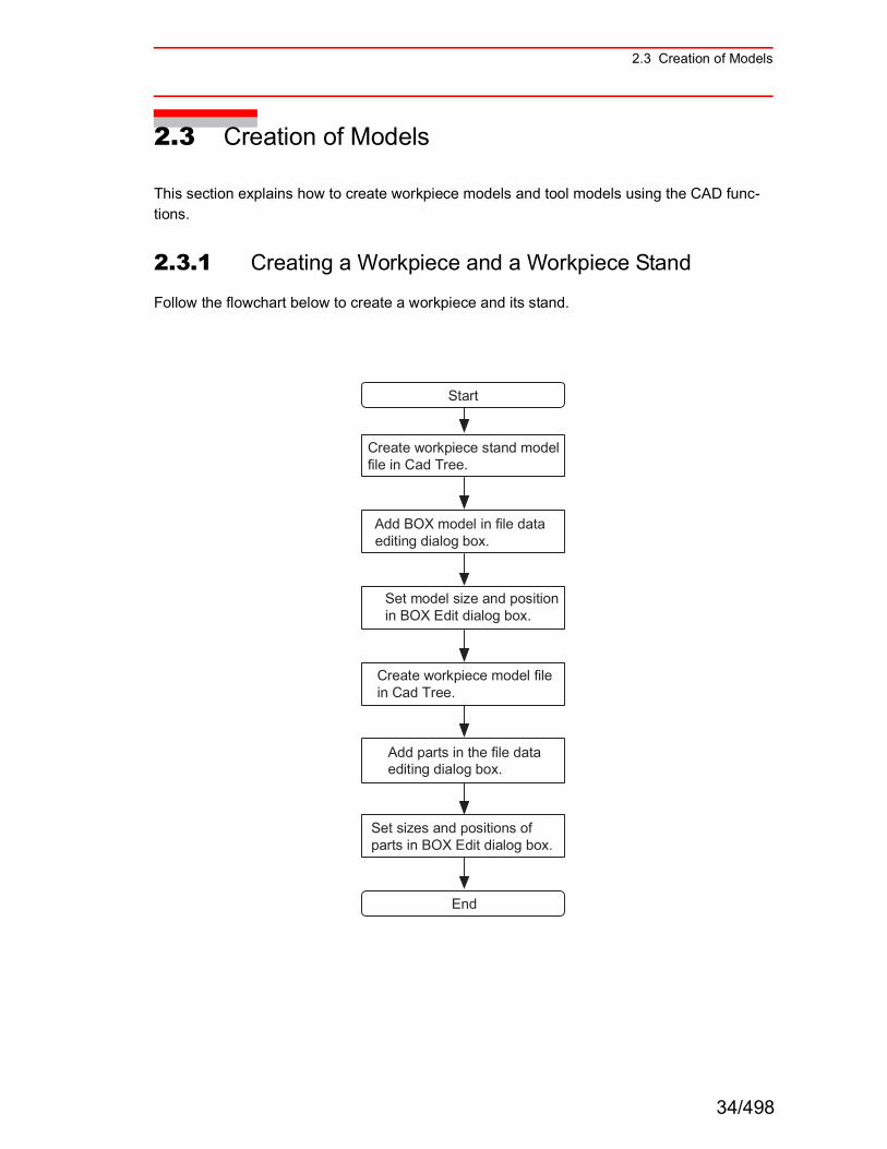
1. The dimensions of the workpiece model and workpiece stand model are shown in the following figure:
2. Click on button or select {CAD Tree} in the {Tool} menu to display the Cad Tree.
3. When the Cad Tree appears, select "world" from the model tree; select {New Model} in the {File} menu, or click the [Add] button.
To create a new model in the model selection screen, verify that the cursor is pointed to "world" so that it will be the parent model.
25
30
200
200
500
400
600
600
Units: mm
Workpiece Stand Model
Workpiece Model
Click the [Add] button
NOTE
35/498
2.3 Creation of Models
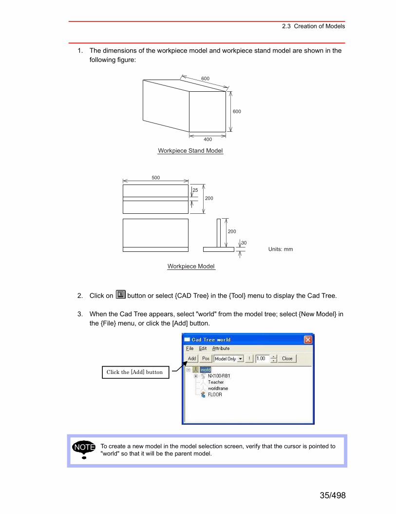
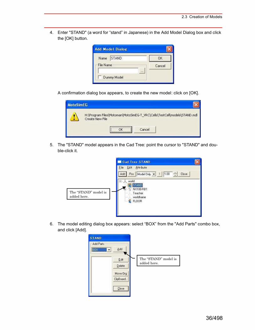
4. Enter "STAND" (a word for ìstandî in Japanese) in the Add Model Dialog box and click the [OK] button.
A confirmation dialog box appears, to create the new model: click on [OK].
5. The "STAND" model appears in the Cad Tree: point the cursor to "STAND" and dou-ble-click it.
6. The model editing dialog box appears: select ìBOXî from the "Add Parts" combo box, and click [Add].
The ìSTANDî model is added here.
The ìSTANDî model is added here.
36/498
2.3 Creation of Models
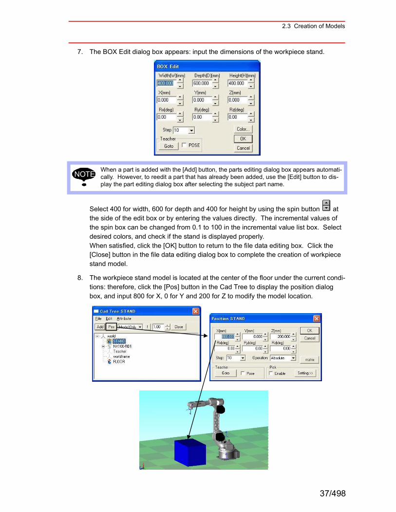
7. The BOX Edit dialog box appears: input the dimensions of the workpiece stand.
Select 400 for width, 600 for depth and 400 for height by using the spin button at the side of the edit box or by entering the values directly. The incremental values of the spin box can be changed from 0.1 to 100 in the incremental value list box. Select desired colors, and check if the stand is displayed properly. When satisfied, click the [OK] button to return to the file data editing box. Click the [Close] button in the file data editing dialog box to complete the creation of workpiece stand model.
8. The workpiece stand model is located at the center of the floor under the current condi-tions: therefore, click the [Pos] button in the Cad Tree to display the position dialog box, and input 800 for X, 0 for Y and 200 for Z to modify the model location.
When a part is added with the [Add] button, the parts editing dialog box appears automati-cally. However, to reedit a part that has already been added, use the [Edit] button to dis-play the part editing dialog box after selecting the subject part name.
NOTE
37/498
2.3 Creation of Models
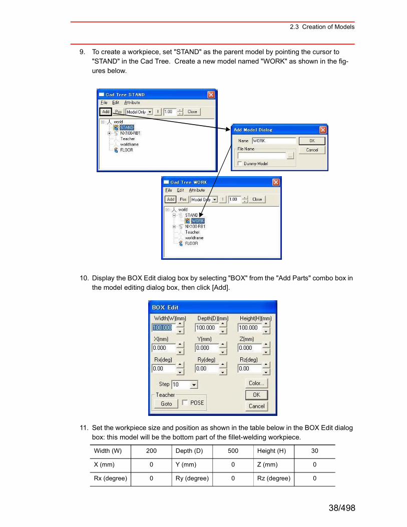
9. To create a workpiece, set "STAND" as the parent model by pointing the cursor to "STAND" in the Cad Tree. Create a new model named "WORK" as shown in the fig-ures below.
10. Display the BOX Edit dialog box by selecting "BOX" from the "Add Parts" combo box in the model editing dialog box, then click [Add].
11. Set the workpiece size and position as shown in the table below in the BOX Edit dialog box: this model will be the bottom part of the fillet-welding workpiece.
Width (W) 200 Depth (D) 500 Height (H) 30
X (mm) 0 Y (mm) 0 Z (mm) 0
Rx (degree) 0 Ry (degree) 0 Rz (degree) 0
38/498
2.3 Creation of Models
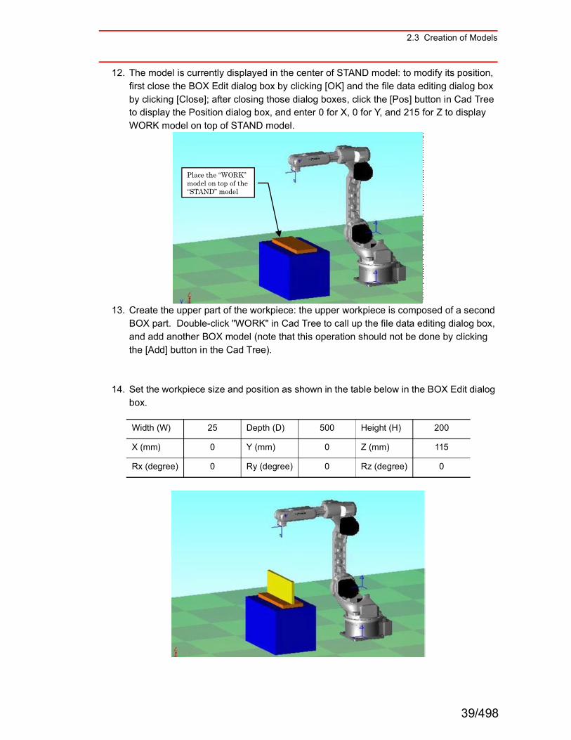
12. The model is currently displayed in the center of STAND model: to modify its position, first close the BOX Edit dialog box by clicking [OK] and the file data editing dialog box by clicking [Close]; after closing those dialog boxes, click the [Pos] button in Cad Tree to display the Position dialog box, and enter 0 for X, 0 for Y, and 215 for Z to display WORK model on top of STAND model.
13. Create the upper part of the workpiece: the upper workpiece is composed of a second BOX part. Double-click "WORK" in Cad Tree to call up the file data editing dialog box, and add another BOX model (note that this operation should not be done by clicking the [Add] button in the Cad Tree).
14. Set the workpiece size and position as shown in the table below in the BOX Edit dialog box.
Width (W) 25 Depth (D) 500 Height (H) 200
X (mm) 0 Y (mm) 0 Z (mm) 115
Rx (degree) 0 Ry (degree) 0 Rz (degree) 0
Place the ìWORKîmodel on top of the ìSTANDî model
39/498
2.3 Creation of Models
15. Check if the workpiece model has been created according to the dimensions specified in the step 1. If the model has different dimensions or to change the color of the model, proceed to the step 16 and 17 to make modifications.
16. Display the BOX Edit dialog box by pointing the cursor to BOX model to be edited among the models added to the Cad Tree, then double-click it.
17. Reedit the workpiece size, etc. in the BOX Edit dialog box. To modify the color of the model, click on the [Color...] button.
40/498
2.3 Creation of Models
2.3.2 Editing Tool Data
This section explains on how to edit the tool data. The tool to be created is a torch for arc-welding. The tool dimensions are: 0 mm for X, 0 mm for Y, and 395 mm for Z.
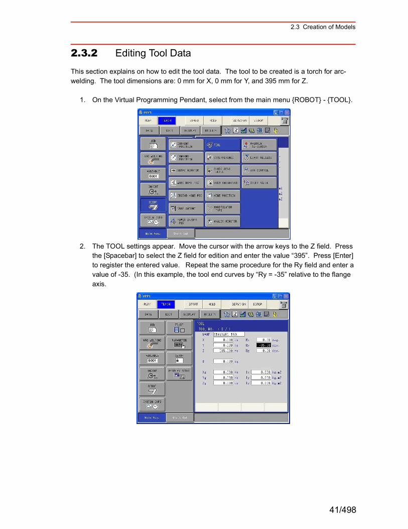
1. On the Virtual Programming Pendant, select from the main menu {ROBOT} - {TOOL}.
2. The TOOL settings appear. Move the cursor with the arrow keys to the Z field. Press the [Spacebar] to select the Z field for edition and enter the value ì395î. Press [Enter] to register the entered value. Repeat the same procedure for the Ry field and enter a value of -35. (In this example, the tool end curves by ìRy = -35î relative to the flange axis.
41/498
2.3 Creation of Models
2.3.3 Adding a Tool Model
There are two ways to add a tool model:(1) Create a tool model with the CAD function of MotoSim EG-VRC.(2) Read a tool model in the HSF format (*.hsf).
First, method (1) is used to explain the creation of a tool model with the MotoSim EG-VRC CAD function.
In method (2), an HSF format model is used; this is explained in " Reading the HSF Format Model " later on.
! Creating and Adding a Tool Model with the CAD Function
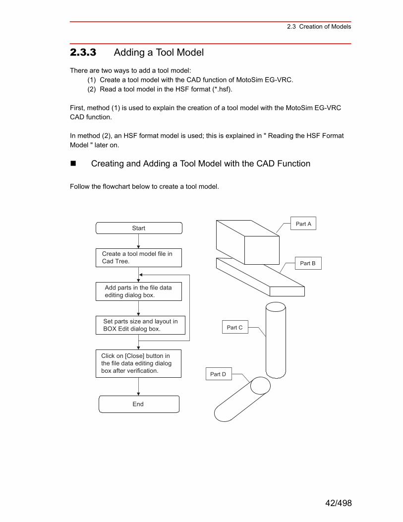
Follow the flowchart below to create a tool model.
Part A
Part C
Part B
Part D
Start
Create a tool model file inCad Tree.
Add parts in the file data editing dialog box.
Set parts size and layout inBOX Edit dialog box.
Click on [Close] button in the file data editing dialog box after verification.
End
42/498
2.3 Creation of Models
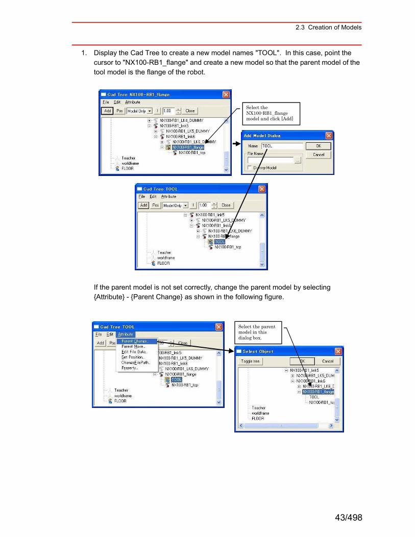
1. Display the Cad Tree to create a new model names "TOOL". In this case, point the cursor to "NX100-RB1_flange" and create a new model so that the parent model of the tool model is the flange of the robot.
If the parent model is not set correctly, change the parent model by selecting {Attribute} - {Parent Change} as shown in the following figure.
Select the NX100-RB1_flange model and click [Add]
Select the parent model in this dialog box.
43/498
2.3 Creation of Models
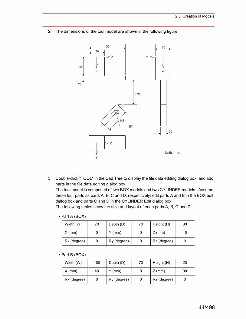
2. The dimensions of the tool model are shown in the following figure:
3. Double-click "TOOL" in the Cad Tree to display the file data editing dialog box, and add parts in the file data editing dialog box. The tool model is composed of two BOX models and two CYLINDER models. Assume these four parts as parts A, B, C and D, respectively: edit parts A and B in the BOX edit dialog box and parts C and D in the CYLINDER Edit dialog box. The following tables show the size and layout of each parts A, B, C and D.
ï Part A (BOX)
ï Part B (BOX)
Width (W) 70 Depth (D) 70 Height (H) 80
X (mm) 0 Y (mm) 0 Z (mm) 40
Rx (degree) 0 Ry (degree) 0 Rz (degree) 0
Width (W) 150 Depth (D) 70 Height (H) 20
X (mm) 40 Y (mm) 0 Z (mm) 90
Rx (degree) 0 Ry (degree) 0 Rz (degree) 0
150 70 70
80
20
170
145
35p
30
X Y
ZZ
X
Y
Units: mm
44/498
2.3 Creation of Models
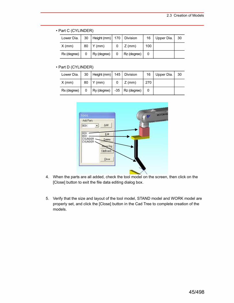
ï Part C (CYLINDER)
ï Part D (CYLINDER)
4. When the parts are all added, check the tool model on the screen, then click on the [Close] button to exit the file data editing dialog box.
5. Verify that the size and layout of the tool model, STAND model and WORK model are properly set, and click the [Close] button in the Cad Tree to complete creation of the models.
Lower Dia. 30 Height (mm) 170 Division 16 Upper Dia. 30
X (mm) 80 Y (mm) 0 Z (mm) 100
Rx (degree) 0 Ry (degree) 0 Rz (degree) 0
Lower Dia. 30 Height (mm) 145 Division 16 Upper Dia. 30
X (mm) 80 Y (mm) 0 Z (mm) 270
Rx (degree) 0 Ry (degree) -35 Rz (degree) 0
45/498

2.3 Creation of Models
! Reading the HSF Format ModelThis section describes how to add a tool model which is provided as an HSF format (*.hsf).If the tool model has been already added in the previous section " Creating and Adding a Tool Model with the CAD Function ", select "TOOL" from the Cad Tree and select "Hide" to hide it.
1. Select "NX100-RB1_tcp" in Cad Tree and click [Add] to display the Add Model Dialog dialog box, then enter "TOOL2" in the Name edit box.
46/498
2.3 Creation of Models
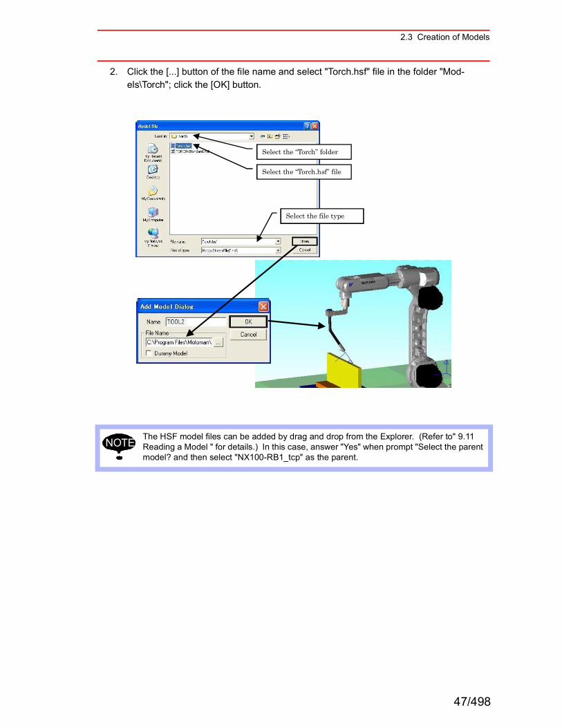
2. Click the [...] button of the file name and select "Torch.hsf" file in the folder "Mod-els\Torch"; click the [OK] button.
The HSF model files can be added by drag and drop from the Explorer. (Refer to" 9.11 Reading a Model " for details.) In this case, answer "Yes" when prompt "Select the parent model? and then select "NX100-RB1_tcp" as the parent.
Select the file type
Select the ìTorchî folder
Select the ìTorch.hsfî file
NOTE
47/498